Futaba T14SG-24G Radio Control User Manual 1
Futaba Corporation Radio Control 1
UserManual.wiki
>
Futaba
>
T14SG-24G User Manual
>
User Manual 1
Contents
1.
User Manual 1
2.
User Manual 2
3.
User Manual 3
User Manual 1
Navigation menu
Upload a User Manual
Namespaces
Wiki Guide
HTML
PDF
Info
Views
User Manual
Discussion / Help
Navigation
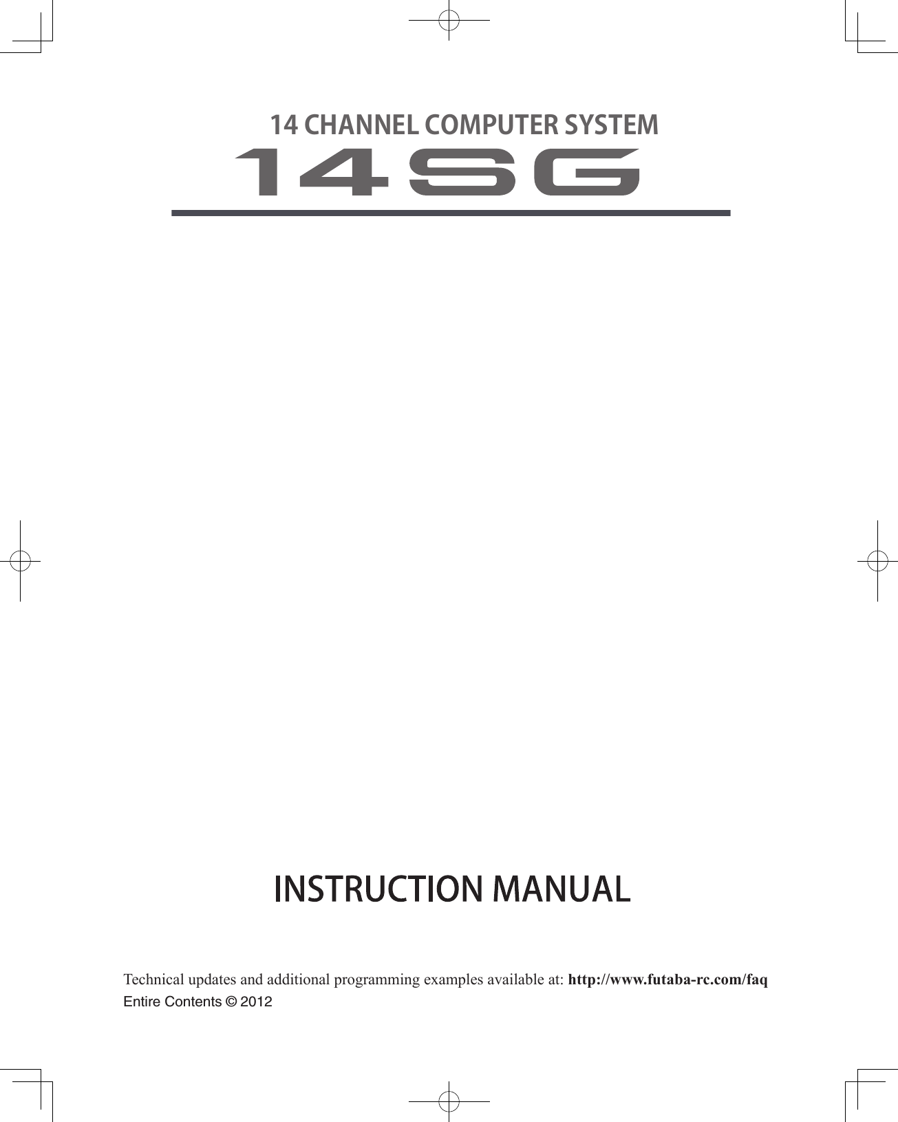
![12 <Before Use>• HT5F1800B Transmitter battery pack - the (1800mAh) transmitter NiMH battery pack may be easily exchanged with a fresh one to provide enough capacity for extended ying sessions.• FT2F2100B/FT2F1700B Transmitter LiFe battery pack can also be used by using an exclusive spacer. However, charge with the charger only for LiFe.• Trainer cord - the optional training cord may be used to help a beginning pilot learn to y easily by placing the instructor on a separate transmitter. Note that the T14SG transmitter may be connected to another T14SG system, as well as to any other models of Futaba transmitters. The T14SG transmitter uses one of the three cord plug types according to the transmitter connected. (Refer to the description at the TRAINER function instructions). The part number of this cord is: FUTM4405.• Servos - there are various kinds of servos. Please choose from the servos of Futaba what suited the model and the purpose of using you. If you utilize a S.BUS system, you should choose a S.BUS servo. An analog servo cannot be used if "FASSTest12CH mode" is used.• Telemetry sensor - please purchase an optional sensor, in order to utilize bidirectional communication system and to acquire the information from a model high up in the sky. [Temperature sensor : SBS-01T] [Altitude sensor : SBS-01A] [RPM sensor magnet type : SBS-01RM][RPM sensor optical type : SBS-01RO] [GPS sensor : SBS-01G] [Voltage sensor : SBS-01V]• Neckstrap - a neckstrap may be connected to your T14SG system to make it easier to handle and improve your ying precision since your hands won’t need to support the transmitter’s weight.• Y-harnesses, servo extensions, hub,etc - Genuine Futaba extensions and Y-harnesses, including a heavy-duty version with heavier wire, are available to aid in your larger model and other installations.• Gyros - a variety of genuine Futaba gyros is available for your aircraft or helicopter needs. • Governor - for helicopter use. Automatically adjusts throttle servo position to maintain a constant head speed regardless of blade pitch, load, weather, etc.• Receivers - various models of Futaba receivers may be purchased for use in other models. (Receivers for FASSTest and FASST,S-FHSS types are available.)• Optional Charger - Futaba CR-2000 NiMH/NiCd Transmitter/Receiver Battery Charger.The following additional accessories are available from your dealer. Refer to a Futaba catalog for more information:](https://usermanual.wiki/Futaba/T14SG-24G.User-Manual-1/User-Guide-1894988-Page-12.png)
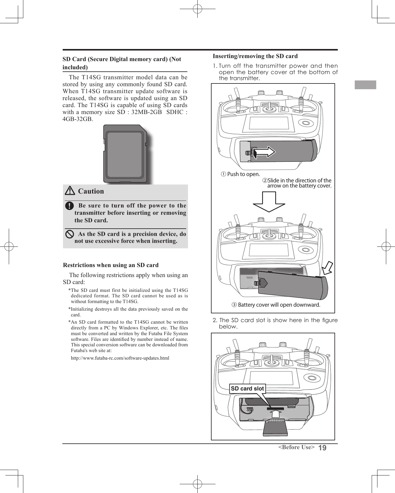
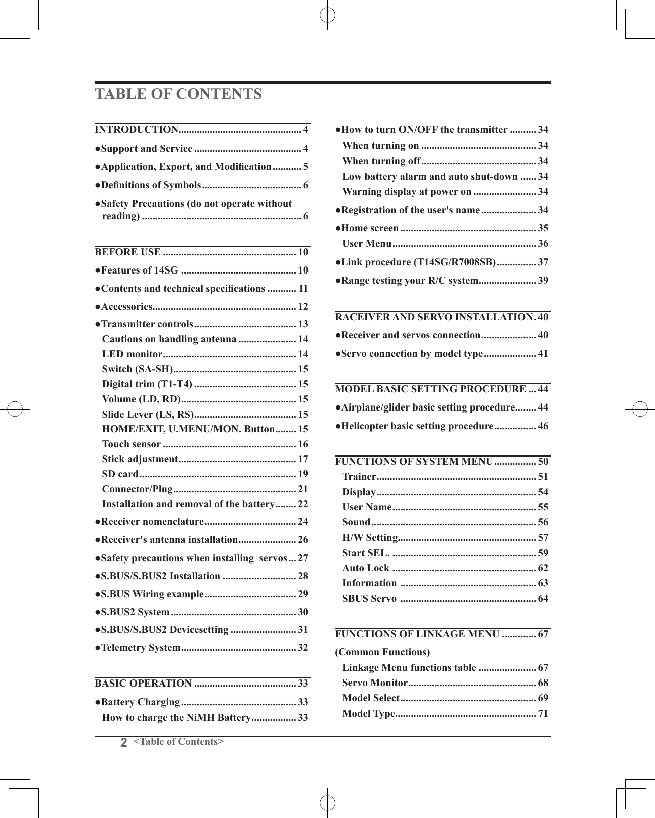
![20 <Before Use>[Inserting the card] Turn the SD card so that the front of the card faces the rear of the transmitter and slide the card into the card slot.*Push in the card until it is rmly seated in the card slot.[Removing the card] When the SD card is pressed in once again, the card will be released from the card slot. and can be removed.3. Close the battery cover.SD card initializationTo use an SD card with the T14SG, the card must rst be formatted. Once formatted, the card does not have to be reformatted. Formatting is performed by the T14SG. [IMPORTANT] When an SD card is formatted for the T14SG, all pre-existing data is destroyed. Do not format a card containing important data. [Formatting procedure]1. Insert the SD card into the SD card slot of the T14SG.2. Turn on the T14SG power. When an unformatted card is inserted into the T14SG, the screen shown below appears.3. If the T14SG is ready to format, move the cursor to [FORMAT] and touch the RTN button. (To cancel formatting, move the cursor to [CANCEL] and touch the RTN button.)4. Move the cursor to [YES] and touch the RTN button.* Formatting starts. During formatting, the [NOW FORMATTING...] message is displayed.*When formatting is completed, The [FORMAT COMPLETED] message is displayed. Depending on the card capacity and speed, formatting may take as long as several minutes. [IMPORTANT] Do not turn off the power until the [FORMAT COMPLETED] message is displayed.5. End formatting by touching the RTN button.SD card reader/writerSaving model data and update files (released from Futaba) to the SD card from your own PC, you can transfer those file to your T14SG transmitter. Equipment for reading and writing SD cards is available at most electronics stores. Stored dataIf you have a problem saving or reading data after a long period of use, we suggest obtaining a new SD card to avoid further difculties.*Futaba is not responsible for compensating any failure or damage to the data stored in the memory card. As such, we suggest that you maintain a backup of your important data contained on your SD card.](https://usermanual.wiki/Futaba/T14SG-24G.User-Manual-1/User-Guide-1894988-Page-20.png)
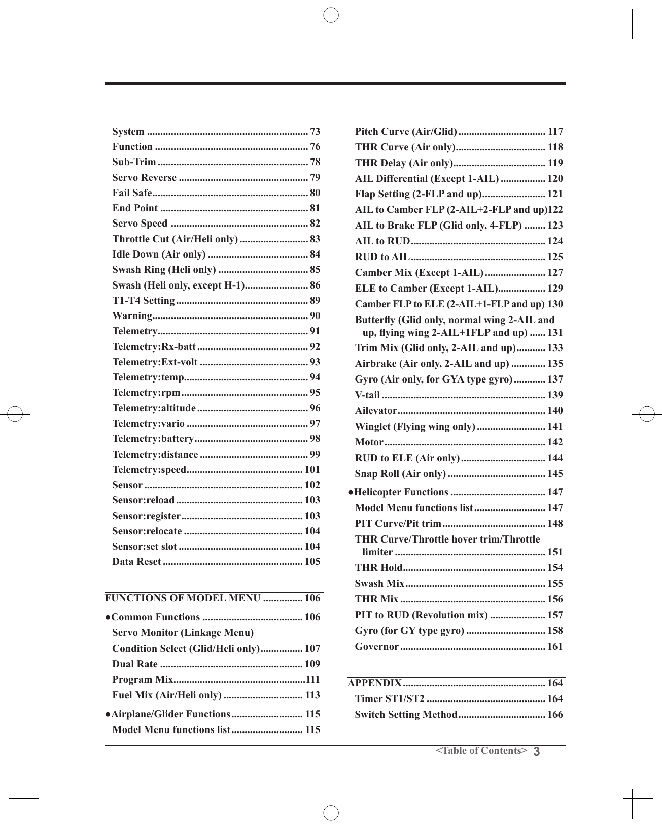
![23<Before Use>When exchanging for the LiFe battery (FT2F2100B/FT2F1700B) of an option.Attachment of the battery1. T14SG to HT5F1800B is removed.2. A LiFe spacer (14SG attachment) is inserted as shown in a gure.3. A LiFe battery (option) is inserted as shown in a gure.4.2P connector of a LiFe battery is connected.5. Close the battery cover completely.6.T14SG is turned on and [LINKAGE MENU]=>[WARNING]=>[LOW BATTERY] is called.7. It changes into 6.0V from 5.6V.Charge of a LiFe batteryNote: LiFe battery cannot be charged with the charger of 14SG attachment. Be sure to remove a battery from T14SG and to charge from the charger only for LiFe.WarningFollow the manual of a LiFe battery.Don't charge the LiFe battery with the NiMH charger of 14SG attachment. * Be sure to remove from T14SG and to charge with the charger only for LiFe.Be sure to change the voltage of LOW BATTERY WARNING into 6.0V from 5.6VLiFe SPACERLiFeBatteryThe balance charge connector is not connected in the state where the battery is set to a transmitter.A LiFe battery is removed from T14SG.Balance charge is carried out from the charger only for LiFe.2P connector is removed from T14SG.The battery state inside T14SGNiMH HT5F1800BLiFe FT2F2100B/1700BLiFe SPACER*About low battery voltage, all the models included in one transmitter are changed in common. It cannot set to different voltage for every model. Moreover, data reset is not carried out.](https://usermanual.wiki/Futaba/T14SG-24G.User-Manual-1/User-Guide-1894988-Page-23.png)
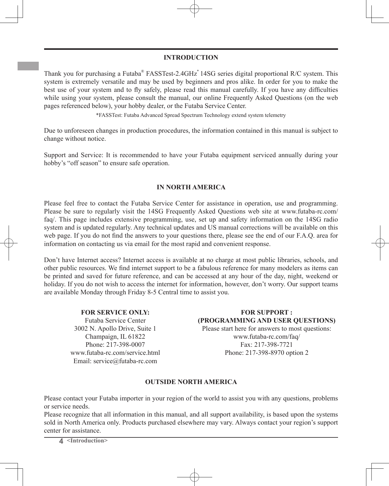
![24 <Before Use>Link/Mode SwitchUse the small plastic screw driver that was included with your receiver. The Link/Mode Switch is also used for the CH mode selection. Extra Voltage ConnectorUse this connector when using a voltage telemetry device to send the battery voltage (DC0 ~ 70V) from the receiver to the transmitter. You will need to purchase the optional External Voltage input cable (CA-RVIN-700) FUTM5551.You can then make a cable with an extra connector to the External voltage connector.Receiver nomenclatureBefore using the receiver, be sure to read the precautions listed in the following pages.Receiver R7008SBConnector"1 through 6": outputs for the channels 1 through 6"7/B": outputs of 7 channels and power. "8/SB": outputs of 8 channels or S.BUS port.[S.BUS Servo S.BUS Gyro ]*When using 8/SB as S.BUS, you have to set CH MODE of the following page to mode B or mode D."S.BUS2": outputs of S.BUS2 port.[S.BUS2 Servo S.BUS2 Gyro Telemetry Sensor ]*When using 9 or more channels, use an S.BUS function or use a second R7008SB and link both to your transmitter.Connector insertion Firmly insert the connector in the direction shown in the gure. Insert the S.BUS2 by turning it 90 degrees.+−Do not connect either a switch or battery in this manner.ReceiverDanger DangerDon't connect a connector, as shown in a before gure.*It will short-circuit, if it connected in this way. A short circuit across the battery terminals may cause abnormal heating, re and burns.WarningS.BUS2 connectorsDon't connect an S.BUS servo / gyro to S.BUS2 connector.LED Monitor This monitor is used to check the CH mode of the receiver.](https://usermanual.wiki/Futaba/T14SG-24G.User-Manual-1/User-Guide-1894988-Page-24.png)
![25<Before Use>R7008SB CH ModeThe R7008SB receiver is a very versatile unit. It has 8 PWM outputs, S.BUS and S.BUS2 outputs. Additionally the PWM outputs can be changed from channels 1-8 to channels 9-14. If you only desire to use it as an 8 channel receiver (without S.BUS), it can be used without any setting changes.The T14SG has the ability to link to two R7008SB receivers. One of them outputting channels 1-8 and the other outputting channels 9-14 giving you 14 PWM channels. Instructions for this configuration and S.BUS operation follow.[How to change the R7008SB Channel mode.]1. Press and hold down the Link/Mode button on the R7008SB receiver.2. Turn the receiver on while holding down the Link/Mode button. when the LED begins to blink green/red the button may be released.3. The LED should now be blinking red in one of the patterns described by the chart below.4. Each press of the Mode/Link button advances the receiver to the next mode.5. When you reach the mode that you wish to operate in, press and hold the Mode/Link button for more than 2 seconds.6. Once locked into the correct mode the LED will change to a solid color.7. Please cycle the receiver(s) power off and back on again after changing the Channel Mode.Receiver connectorSetting channelMode A1 ~ 8CHMode B1 ~ 7CHMode C9 ~ 14CHMode D9 ~ 14CH1 11992 2 2 10 103 3 3 11 114 4 4 12 125 5 5 13 136 6 6 14 147/B 7 7 - -8/SB 8 S.BUS - S.BUSRed LED blink 1time 2time 3time 4timeR7008SB CH MODE TABLEDangerDon't touch wiring. * There is a danger of receiving an electric shock.Do not short-circuit the battery terminals.* A short circuit across the battery terminals may cause abnormal heating, re and burns.Please double check your polarity ( +and -) when hooking up your connectors. * If + and - of wiring are mistaken, it will damage, ignite and explode.Don’t connection to Extra Voltage before turning on a receiver power supply.](https://usermanual.wiki/Futaba/T14SG-24G.User-Manual-1/User-Guide-1894988-Page-25.png)
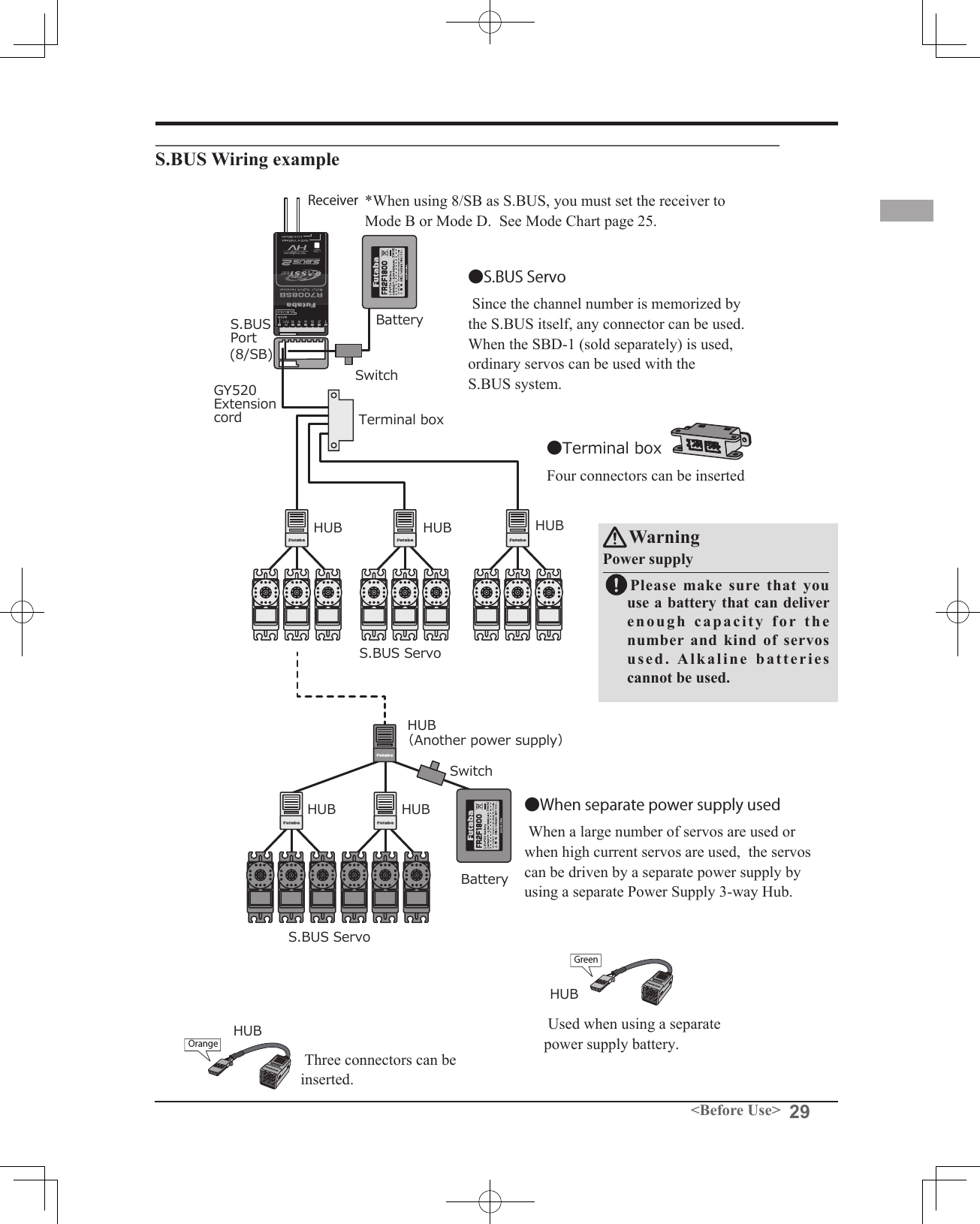
![30 <Before Use>S.BUS2 System When using the S.BUS2 port, an impressive array of telemetry sensors may be utilized. Receiver port S.BUS ServoS.BUS GyroS.BUS2 ServoS.BUS2 Gyro Telemetry sensorS.BUS ○ ○ ×S.BUS2 × (※) ○ ○S.BUS2 TABLE(※)Don't connect S.BUS Servo, S.BUS Gyro to S.BUS2 connector. S.BUS2PortS.BUSPort(8/SB)HubHub Hub HubRudder ServoS.BUS2 ServoS.BUS ServoS.BUS2 servoConnection is possibleS.BUS2 gyroConnection is possibleS.BUS servoConnection is impossibleTelemetry sensorConnection is impossibleS.BUS2GYROCH Mode is set to ModeB [D]. +Telemetry SensorS.BUS servos and gyros and S.BUS2 servos and gyros must be used in the correct receiver ports. Please refer to the instruction manual to make sure you connect to the correct one.](https://usermanual.wiki/Futaba/T14SG-24G.User-Manual-1/User-Guide-1894988-Page-30.png)