Contents
- 1. User Manual 1
- 2. User Manual 2
- 3. User Manual 3
User Manual 1
14 CHANNEL COMPUTER SYSTEM
TM
TM
Technical updates and additional programming examples available at: http://www.futaba-rc.com/faq
Entire Contents © 2012
2<Table of Contents>
INTRODUCTION............................................... 4
●Support and Service ......................................... 4
●Application, Export, and Modication ........... 5
●Denitions of Symbols ...................................... 6
●Safety Precautions (do not operate without
reading) ............................................................. 6
BEFORE USE ................................................... 10
●Features of 14SG ............................................ 10
●Contents and technical specications ........... 11
●Accessories ....................................................... 12
●Transmitter controls ....................................... 13
Cautions on handling antenna ...................... 14
LED monitor ................................................... 14
Switch (SA-SH) ............................................... 15
Digital trim (T1-T4) ....................................... 15
Volume (LD, RD) ............................................ 15
Slide Lever (LS, RS) ....................................... 15
HOME/EXIT, U.MENU/MON. Button ........ 15
Touch sensor ................................................... 16
Stick adjustment ............................................. 17
SD card ............................................................ 19
Connector/Plug ............................................... 21
Installation and removal of the battery ........ 22
●Receiver nomenclature ................................... 24
●Receiver's antenna installation ...................... 26
●Safety precautions when installing servos ... 27
●S.BUS/S.BUS2 Installation ............................ 28
●S.BUS Wiring example ................................... 29
●S.BUS2 System ................................................ 30
●S.BUS/S.BUS2 Devicesetting ......................... 31
●Telemetry System ............................................ 32
BASIC OPERATION ....................................... 33
●Battery Charging ............................................ 33
How to charge the NiMH Battery ................. 33
●How to turn ON/OFF the transmitter .......... 34
When turning on ............................................ 34
When turning off ............................................ 34
Low battery alarm and auto shut-down ...... 34
Warning display at power on ........................ 34
●Registration of the user's name ..................... 34
●Home screen .................................................... 35
User Menu ....................................................... 36
●Link procedure (T14SG/R7008SB) ............... 37
●Range testing your R/C system...................... 39
RACEIVER AND SERVO INSTALLATION . 40
●Receiver and servos connection ..................... 40
●Servo connection by model type .................... 41
MODEL BASIC SETTING PROCEDURE ... 44
●Airplane/glider basic setting procedure ........ 44
●Helicopter basic setting procedure ................ 46
FUNCTIONS OF SYSTEM MENU ................ 50
Trainer ............................................................. 51
Display ............................................................. 54
User Name ....................................................... 55
Sound ............................................................... 56
H/W Setting ..................................................... 57
Start SEL. ....................................................... 59
Auto Lock ....................................................... 62
Information .................................................... 63
SBUS Servo .................................................... 64
FUNCTIONS OF LINKAGE MENU ............. 67
(Common Functions)
Linkage Menu functions table ...................... 67
Servo Monitor ................................................. 68
Model Select .................................................... 69
Model Type...................................................... 71
TABLE OF CONTENTS
3
<Table of Contents>
System ............................................................. 73
Function .......................................................... 76
Sub-Trim ......................................................... 78
Servo Reverse ................................................. 79
Fail Safe ........................................................... 80
End Point ........................................................ 81
Servo Speed .................................................... 82
Throttle Cut (Air/Heli only) .......................... 83
Idle Down (Air only) ...................................... 84
Swash Ring (Heli only) .................................. 85
Swash (Heli only, except H-1) ........................ 86
T1-T4 Setting .................................................. 89
Warning ........................................................... 90
Telemetry......................................................... 91
Telemetry:Rx-batt .......................................... 92
Telemetry:Ext-volt ......................................... 93
Telemetry:temp............................................... 94
Telemetry:rpm ................................................ 95
Telemetry:altitude .......................................... 96
Telemetry:vario .............................................. 97
Telemetry:battery ........................................... 98
Telemetry:distance ......................................... 99
Telemetry:speed ............................................ 101
Sensor ............................................................ 102
Sensor:reload ................................................ 103
Sensor:register .............................................. 103
Sensor:relocate ............................................. 104
Sensor:set slot ............................................... 104
Data Reset ..................................................... 105
FUNCTIONS OF MODEL MENU ............... 106
●Common Functions ...................................... 106
Servo Monitor (Linkage Menu)
Condition Select (Glid/Heli only) ................ 107
Dual Rate ...................................................... 109
Program Mix ..................................................111
Fuel Mix (Air/Heli only) .............................. 113
●Airplane/Glider Functions ........................... 115
Model Menu functions list ........................... 115
Pitch Curve (Air/Glid) ................................. 117
THR Curve (Air only) .................................. 118
THR Delay (Air only) ................................... 119
AIL Differential (Except 1-AIL) ................. 120
Flap Setting (2-FLP and up) ........................ 121
AIL to Camber FLP (2-AIL+2-FLP and up)122
AIL to Brake FLP (Glid only, 4-FLP) ........ 123
AIL to RUD ................................................... 124
RUD to AIL ................................................... 125
Camber Mix (Except 1-AIL) ....................... 127
ELE to Camber (Except 1-AIL) .................. 129
Camber FLP to ELE (2-AIL+1-FLP and up) 130
Buttery (Glid only, normal wing 2-AIL and
up, ying wing 2-AIL+1FLP and up) ...... 131
Trim Mix (Glid only, 2-AIL and up) ........... 133
Airbrake (Air only, 2-AIL and up) ............. 135
Gyro (Air only, for GYA type gyro) ............ 137
V-tail .............................................................. 139
Ailevator ........................................................ 140
Winglet (Flying wing only) .......................... 141
Motor ............................................................. 142
RUD to ELE (Air only) ................................ 144
Snap Roll (Air only) ..................................... 145
●Helicopter Functions .................................... 147
Model Menu functions list ........................... 147
PIT Curve/Pit trim ....................................... 148
THR Curve/Throttle hover trim/Throttle
limiter ......................................................... 151
THR Hold ...................................................... 154
Swash Mix ..................................................... 155
THR Mix ....................................................... 156
PIT to RUD (Revolution mix) ..................... 157
Gyro (for GY type gyro) .............................. 158
Governor ....................................................... 161
APPENDIX ...................................................... 164
Timer ST1/ST2 ............................................. 164
Switch Setting Method ................................. 166
4<Introduction>
INTRODUCTION
Thank you for purchasing a Futaba® FASSTest-2.4GHz* 14SG series digital proportional R/C system. This
system is extremely versatile and may be used by beginners and pros alike. In order for you to make the
best use of your system and to y safely, please read this manual carefully. If you have any difculties
while using your system, please consult the manual, our online Frequently Asked Questions (on the web
pages referenced below), your hobby dealer, or the Futaba Service Center.
*FASSTest: Futaba Advanced Spread Spectrum Technology extend system telemetry
Due to unforeseen changes in production procedures, the information contained in this manual is subject to
change without notice.
Support and Service: It is recommended to have your Futaba equipment serviced annually during your
hobby’s “off season” to ensure safe operation.
IN NORTH AMERICA
Please feel free to contact the Futaba Service Center for assistance in operation, use and programming.
Please be sure to regularly visit the 14SG Frequently Asked Questions web site at www.futaba-rc.com/
faq/. This page includes extensive programming, use, set up and safety information on the 14SG radio
system and is updated regularly. Any technical updates and US manual corrections will be available on this
web page. If you do not nd the answers to your questions there, please see the end of our F.A.Q. area for
information on contacting us via email for the most rapid and convenient response.
Don’t have Internet access? Internet access is available at no charge at most public libraries, schools, and
other public resources. We nd internet support to be a fabulous reference for many modelers as items can
be printed and saved for future reference, and can be accessed at any hour of the day, night, weekend or
holiday. If you do not wish to access the internet for information, however, don’t worry. Our support teams
are available Monday through Friday 8-5 Central time to assist you.
FOR SERVICE ONLY:
Futaba Service Center
3002 N. Apollo Drive, Suite 1
Champaign, IL 61822
Phone: 217-398-0007
www.futaba-rc.com/service.html
Email: service@futaba-rc.com
FOR SUPPORT :
(PROGRAMMING AND USER QUESTIONS)
Please start here for answers to most questions:
www.futaba-rc.com/faq/
Fax: 217-398-7721
Phone: 217-398-8970 option 2
OUTSIDE NORTH AMERICA
Please contact your Futaba importer in your region of the world to assist you with any questions, problems
or service needs.
Please recognize that all information in this manual, and all support availability, is based upon the systems
sold in North America only. Products purchased elsewhere may vary. Always contact your region’s support
center for assistance.
5
<Introduction>
Application, Export, and Modication
1. This product may be used for model airplane or surface (boat, car, robot) use. It is not intended for use
in any application other than the control of models for hobby and recreational purposes. The product is
subject to regulations of the Ministry of Radio/Telecommunications and is restricted under Japanese law to
such purposes.
2. Exportation precautions:
(a) When this product is exported from the country of manufacture, its use is to be approved by the laws
governing the country of destination which govern devices that emit radio frequencies. If this product is
then re-exported to other countries, it may be subject to restrictions on such export. Prior approval of the
appropriate government authorities may be required. If you have purchased this product from an exporter
outside your country, and not the authorized Futaba distributor in your country, please contact the seller
immediately to determine if such export regulations have been met.
(b) Use of this product with other than models may be restricted by Export and Trade Control Regulations,
and an application for export approval must be submitted. This equipment must not be utilized to operate
equipment other than radio controlled models.
3. Modification, adjustment, and replacement of parts: Futaba is not responsible for unauthorized
modification, adjustment, and replacement of parts on this product. Any such changes may void the
warranty.
Compliance Information Statement (for U.S.A.)
This device, trade name Futaba Corporation of America, model number R7008SB, complies with part 15 of
the FCC Rules. Operation is subject to the following two conditions:
(1) This device may not cause harmful interference, and
(2) This device must accept any interference received, including interference that may cause undesired
operation.
The responsible party of this device compliance is:
Futaba Service Center
3002 N Apollo Drive Suite 1, Champaign, IL 61822 U.S.A.
TEL (217)398-8970 or E-mail: support@futaba-rc.com (Support)
TEL (217)398-0007 or E-mail: service@futaba-rc.com (Service)
The RBRC. SEAL on the nickel-cadmium battery contained in Futaba products indicates that
Futaba Corporation of America is voluntarily participating in an industry-wide program to collect
and recycle these batteries at the end of their useful lives, when taken out of service within the
United States. The RBRC. program provides a convenient alternative to placing used nickel-
cadmium batteries into the trash or municipal waste system, which is illegal in some areas.
(for USA)
You may contact your local recycling center for information on where to return the spent battery. Please
call 1-800-8BATTERY for information on NiCd battery recycling in your area. Futaba Corporation of
America's involvement in this program is part of its commitment to protecting our environment and
conserving natural resources.
*RBRC is a trademark of the Rechargeable Battery Recycling Corporation.
6<Introduction>
Federal Communications Commission Interference Statement (for U.S.A.)
This equipment has been tested and found to comply with the limits for a Class B digital device, pursuant
to Part 15 of the FCC Rules. These limits are designed to provide reasonable protection against harmful
interference in a residential installation.
This equipment generates, uses and can radiate radio frequency energy and, if not installed and used in
accordance with the instructions, may cause harmful interference to radio communications. However, there
is no guarantee that interference will not occur in a particular installation. If this equipment does cause
harmful interference to radio or television reception, which can be determined by turning the equipment off
and on, the user is encouraged to try to correct the interference by one or more of the following measures:
--Reorient or relocate the receiving antenna.
--Increase the separation between the equipment and receiver.
--Consult the dealer or your Futaba Serivce center for help.
CAUTION:
To assure continued FCC compliance:
Any changes or modications not expressly approved by the grantee of this device could void the user's
authority to operate the equipment.
Exposure to Radio Frequency Radiation
To comply with FCC RF exposure compliance requirements, a separation distance of at least 20cm must be
maintained between the antenna of this device and all persons.
This device must not be co-located or operating in conjunction with any other antenna or transmitter.
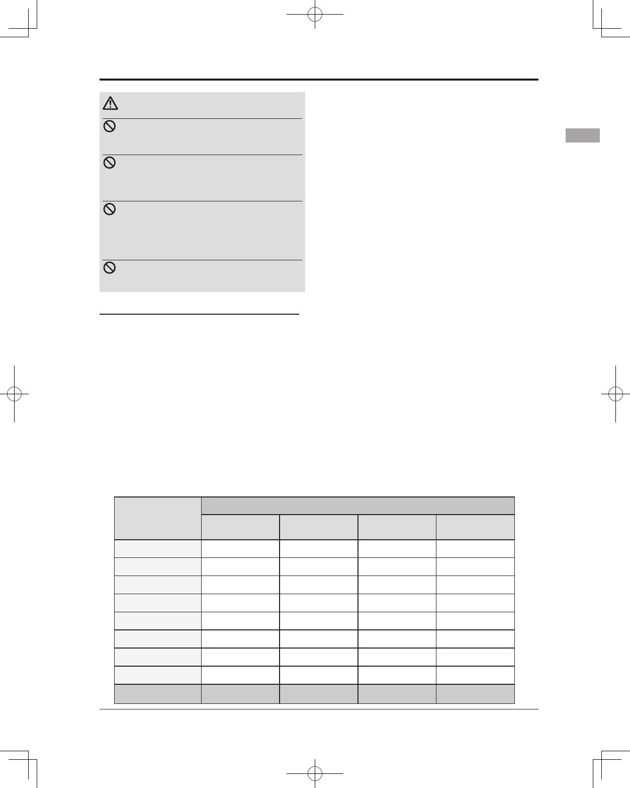
Meaning of Special Markings
Pay special attention to safety where indicated by the following marks:
DANGER - Procedures which may lead to dangerous conditions and cause death/serious injury if not
carried out properly.
WARNING - Procedures which may lead to a dangerous condition or cause death or serious injury
to the user if not carried out properly, or procedures where the probability of supercial injury or
physical damage is high.
CAUTION - Procedures where the possibility of serious injury to the user is small, but there is a
danger of injury, or physical damage, if not carried out properly.
= Prohibited = Mandatory
Warning: Always keep electrical components away from small children.
FLYING SAFETY
WARNING
To ensure the safety of yourself and others, please observe the following precautions:
Have regular maintenance performed. Although your 14SG protects the model memories with
non-volatile EEPROM memory (which does not require periodic replacement) and not a battery, the
transmitter still should have regular checkups for wear and tear. We recommend sending your system
to the Futaba Service Center annually during your non-ying-season for a complete checkup and
service.
7
<Introduction>
NiMH/NiCd Battery
Charge the batteries! (See Charging the NiCd batteries, for details.) Always recharge the transmitter
and receiver batteries before each ying session. A low battery will soon die potentially, causing loss
of control and a crash. When you begin your ying session, reset your T14SG’s built-in timer, and
during the session pay attention to the duration of usage.
Stop ying long before your batteries become low on charge. Do not rely on your radio’s low
battery warning systems, intended only as a precaution, to tell you when to recharge. Always
check your transmitter and receiver batteries prior to each ight.
Where to Fly
We recommend that you fly at a recognized model airplane flying field. You can find model clubs
and fields by asking your nearest hobby dealer, or in the US by contacting the Academy of Model
Aeronautics.
You can also contact the national Academy of Model Aeronautics (AMA), which has more than 2,500
chartered clubs across the country. Through any one of them, instructor training programs and insured
newcomer training are available. Contact the AMA at the address or toll-free phone number below.
Academy of Model Aeronautics
5161 East Memorial Drive
Muncie, IN 47302
Tele. (800) 435-9262
Fax (765) 289-4248
or via the Internet at http:\\www.modelaircraft.org
Always pay particular attention to the ying eld’s rules, as well as the presence and location
of spectators, the wind direction, and any obstacles on the eld. Be very careful ying in areas near
power lines, tall buildings, or communication facilities as there may be radio interference in their
vicinity.
8<Introduction>
NiMH/NiCd Battery Safety and Handling instructions
IMPORTANT!
Use only the Futaba special charger included with this set or other chargers approved by Futaba to
charge the NiMH batteries in the T14SG transmitter included with this set.
It is important to understand the operating characteristics of NiMH/NiCd batteries.Always read the
specications printed on the label of your NiMH/NiCd battery and charger prior to use. Failure to follow
the proceeding precautions can quickly result in severe, permanent damage to the batteries and its
surroundings and possibly result in a FIRE!
IMPORTANT PRECAUTIONS
Do not attempt to disassemble NiMH/NiCd packs or cells.
Do not allow NiMH/NiCd cells to come in contact with moisture or water at any time.
Always provide adequate ventilation around NiMH/NiCd batteries during charge, discharge, while in
use, and during storage.
Do not leave a NiMH/NiCd battery unattended at any time while being charged or discharged.
Do not attempt to charge NiMH/NiCd batteries with a charger that is NOT designed for NiMH/NiCd
batteries, as permanent damage to the battery and charger could result.
Always charge NiMH/NiCd batteries in a reproof location. Do not charge or discharge NiMH/NiCd
batteries on carpet, a cluttered workbench, near paper, plastic, vinyl, leather or wood, or inside an R/
C model or full-sized automobile! Monitor the charge area with a smoke or re alarm.
Do not charge NiMH/NiCd batteries at currents greater than the “1C” rating of the battery (“C”
equals the rated capacity of the battery).
Do not allow NiMH/NiCd cells to overheat at any time! Cells which reach greater than 140 degrees
Fahrenheit (60°C) should be placed in a reproof location.
NiMH/NiCd cells will not charge fully when too cold or show full charge.
It is normal for the batteries to become warm during charging, but if the charger or battery becomes
excessively hot disconnect the battery from the charger immediately!! Always inspect a battery which
has previously overheated for potential damage, and do not re-use if you suspect it has been damaged
in any way.
Do not use a NiMH/NiCd battery if you suspect physical damage has occurred to the pack. Carefully
inspect the battery for even the smallest of dents, cracks, splits, punctures or damage to the wiring
and connectors. DO NOT allow the battery’s internal electrolyte to get into eyes or on skin—wash
affected areas immediately if they come in contact with the electrolyte. If in doubt, place the battery
in a re-proof location for at least 30 minutes.
Do not store batteries near an open ame or heater.
Do not discharge NiMH/NiCd batteries at currents which exceed the discharge current rating of the
battery.
Always store NiMH/NiCd cells/packs in a secure location away from children.
Never remove the SD card or turn off power
while entering data.
Never store the SD card where it may be
subject to strong static electricity or magnetic
elds.
Do not expose the SD card to direct sunlight,
excessive humidity or corrosive environments.
Do not expose the SD card to dirt, moisture,
water or uids of any kind.
Always hold the SD card by the edges during
installation and removal.
Be certain to insert the SD card in the correct
direction.
Secure Digital (SD) Memory Card Handling Instructions
(SD card is not included with this set)
9
<Introduction>
At the ying eld
To prevent possible damage to your radio gear, turn the power switches on and off in the proper
sequence:
1. Pull throttle stick to idle position, or otherwise disarm your motor/engine.
2. Turn on the transmitter power and allow your transmitter to reach its home screen.
3. Conrm the proper model memory has been selected.
4. Turn on your receiver power.
5. Test all controls. If a servo operates abnormally, don’t attempt to y until you determine the cause of
the problem.
Test to ensure that the FailSafe settings are correct after adjusting them. Turn the transmitter off and
conrm the proper surface/throttle movements. Turn the transmitter back on.
6. Start your engine.
7. Complete a full range check.
8. After ying, bring your throttle stick to idle position, engage any kill switches or otherwise disarm
your motor/engine.
9. Turn off receiver power.
10. Turn off transmitter power.
If you do not turn on your system in this order, you may damage your servos or control surfaces,
flood your engine, or in the case of electric-powered or gasoline-powered models, the engine may
unexpectedly turn on and cause a severe injury.
While you are getting ready to y, if you place your transmitter on the ground, be sure that the
wind won't tip it over. If it is knocked over, the throttle stick may be accidentally moved, causing
the engine to speed up. Also, damage to your transmitter may occur.
In order to maintain complete control of your aircraft it is important that it remains visible at all
times. Flying behind large objects such as buildings, grain bins, etc. is not suggested. Doing so may
result in the reduction of the quality of the radio frequency link to the model.
Do not grasp the transmitter's antenna during ight. Doing so may degrade the quality of the
radio frequency transmission.
As with all radio frequency transmissions, the strongest area of signal transmission is from the sides
of the transmitter's antenna. As such, the antenna should not be pointed directly at the model. If your
ying style creates this situation, easily move the antenna to correct this situation.
Don’t fly in the rain! Water or moisture may enter the transmitter through the antenna or stick
openings and cause erratic operation or loss of control. If you must fly in wet weather during a
contest, be sure to cover your transmitter with a plastic bag or waterproof barrier. Never fly if
lightning is expected.
10 <Before Use>
BEFORE USE
Features
FASSTest system
The T14SG transmitter has adopted the newly developed bidirectional communication system
"FASSTest".Data from the receiver can be checked in your transmitter. FASSTest is a maximum 14
channels (linear 12 channels + switch 2 channels) 2.4GHz dedicated system.
S.BUS2 system
By using the S.BUS2 system multiple servos, gyros and telemetry sensors are easily installed with a
minimum amount of cables.
Model types
Six swash types are available for helicopters. Six types of main wings and three types of tail wings are
available for airplanes and gliders. Functions and mixing functions necessary for each model type are set in
advance at the factory.
Data input
Large graphic LCD and new type Touch Sensor substantially improve ease of setup.
Stick
Improved feel, adjustable length and tension.
Ni-MH battery
T14SG is operated by a 6.0 V/1,800 mAh Nickel-Metal Hydride battery.
SD card (Secure Digital memory card) (Not included)
Model data can be saved to an SD card (SD:32MB-2GB SDHC:4GB-32GB). When T14SG transmitter
software les are released, the software can be updated by using an SD card update.
Edit button
Two edit buttons are provided, and the operating screen can be immediately “Returned” to the HOME
screen during operation. Setting operation can be performed easily by combining this button with a touch
sensor.
Vibration function
Selects a function that alerts the operator to various alarms and timers by vibrating the transmitter in
addition to sounding a buzzer.
11
<Before Use>
Contents and Technical Specications
(Specications and ratings are subject to change without notice.)
Your 14SG includes the following components:
• T14SG transmitter for airplanes or helicopters
• R7008SB Receiver
• HT5F1800B NiMH battery & Charger
• Li-Fe spacer for optional FT2F2100B/FT2F1700B LiFe battery pack.
• Switch harness
• Neck strap
*The set contents depend on the type of set.
Transmitter T14SG
(2-stick, 14-channel, FASSTest-2.4G system)
Transmitting frequency: 2.4GHz band
System: FASSTest14CH, FASSTest12CH, FASST MULT, FASST 7CH, S-FHSS, switchable
Power supply: 6.0V HT5F1800B NiMH battery
Receiver R7008SB
(FASSTest-2.4G system, dual antenna diversity, S.BUS system)
Power requirement: 3.7V~7.4V battery or regulated output from ESC, etc. (*1)
Size: 0.98 x 1.86 x 0.56 in. (24.9 x 47.3 x 14.3 mm)
Weight: 0.38 oz. (10.9g)
(*1) When using ESC's make sure that the regulated output capacity meets your usage application.
Note: The battery in the T14SG transmitter is not connected to the battery
connector at initial. Please connect the battery connector before use.
12 <Before Use>
• HT5F1800B Transmitter battery pack - the (1800mAh) transmitter NiMH battery pack may be
easily exchanged with a fresh one to provide enough capacity for extended ying sessions.
• FT2F2100B/FT2F1700B Transmitter LiFe battery pack can also be used by using an exclusive
spacer. However, charge with the charger only for LiFe.
• Trainer cord - the optional training cord may be used to help a beginning pilot learn to y easily
by placing the instructor on a separate transmitter. Note that the T14SG transmitter may be
connected to another T14SG system, as well as to any other models of Futaba transmitters. The
T14SG transmitter uses one of the three cord plug types according to the transmitter connected.
(Refer to the description at the TRAINER function instructions). The part number of this cord is:
FUTM4405.
• Servos - there are various kinds of servos. Please choose from the servos of Futaba what suited
the model and the purpose of using you. If you utilize a S.BUS system, you should choose a S.BUS
servo. An analog servo cannot be used if "FASSTest12CH mode" is used.
• Telemetry sensor - please purchase an optional sensor, in order to utilize bidirectional
communication system and to acquire the information from a model high up in the sky.
[Temperature sensor : SBS-01T] [Altitude sensor : SBS-01A] [RPM sensor magnet type : SBS-
01RM][RPM sensor optical type : SBS-01RO] [GPS sensor : SBS-01G] [Voltage sensor : SBS-
01V]
• Neckstrap - a neckstrap may be connected to your T14SG system to make it easier to handle and
improve your ying precision since your hands won’t need to support the transmitter’s weight.
• Y-harnesses, servo extensions, hub,etc - Genuine Futaba extensions and Y-harnesses, including
a heavy-duty version with heavier wire, are available to aid in your larger model and other
installations.
• Gyros - a variety of genuine Futaba gyros is available for your aircraft or helicopter needs.
• Governor - for helicopter use. Automatically adjusts throttle servo position to maintain a constant
head speed regardless of blade pitch, load, weather, etc.
• Receivers - various models of Futaba receivers may be purchased for use in other models.
(Receivers for FASSTest and FASST,S-FHSS types are available.)
• Optional Charger - Futaba CR-2000 NiMH/NiCd Transmitter/Receiver Battery Charger.
The following additional accessories are available from your dealer. Refer to a Futaba catalog
for more information:
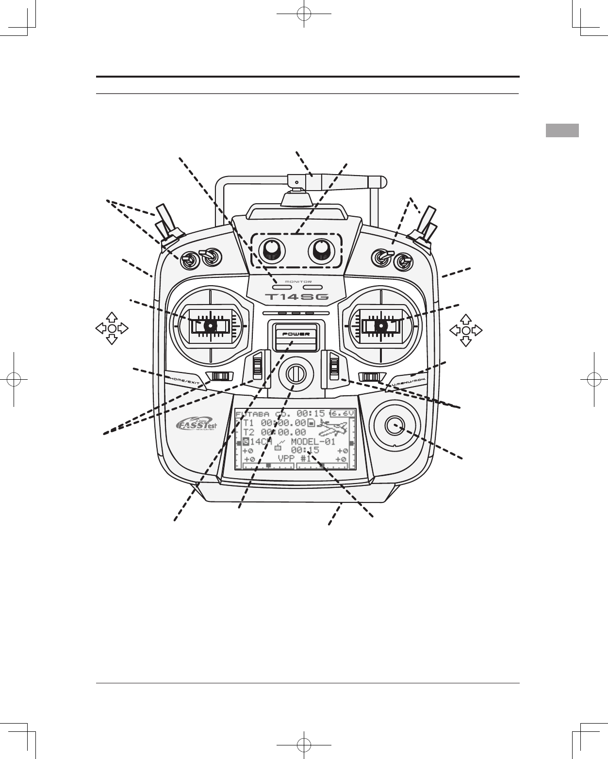
13
<Before Use>
●Antenna
●Monitor LED
●LCD
●Battery Cover
●Neck Strap Attachment
●Switch(SC,SD,SG,SH)
●Switch(SA,SB,SE,SF)
●Slide Lever(LS)
●Slide Lever(RS)
●Digital Trim
(T3,T4)
●Power Switch
●Volume(LD,RD)
●Stick ●Stick
●Digital Trim
(T1,T2)
●U.MENU/MON.
(User Menu/
Servo Monitor)
Button
●HOME/EXIT
Button
*It slides upwards and turns on.
●SensorTouchTM
(SYS,LNK,
MDL,RTN,S1)
(J1)
(J2)
(J4)
(J3)
Transmitter controls
14 <Before Use>
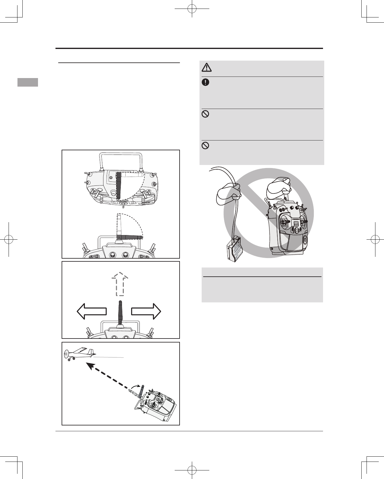
Transmitter's Antenna:
As with all radio frequency transmissions,
the strongest area of signal transmission is from
the sides of the transmitter's antenna. As such,
the antenna should not be pointed directly at the
model. If your ying style creates this situation,
easily move the antenna to correct this situation.
LED (Left)
Displays the "non-default condition" warning.
• Blinking
Power switch is turned on when any
condition switch is activated (in the ON
state).
LED (Right)
Displays the state of radio frequency
transmission.
• Off
Radio waves are in the OFF state.
• On
Radio waves are being transmitted.
• Blinking
Range check mode.
Monitor LED display
The status of the transmitter is displayed by
LED at the bottom left and right sides of the
"T14SG" logo.
•Rotating antenna
The antenna can be rotated 90 degrees and angled
90 degrees. Forcing the antenna further than this
can damage it. The antenna is not removable.
Caution
Please do not grasp the transmitter's
antenna during ight.
Doing so may degrade the quality of the RF
transmission to the model
Do not carry the transmitter by the
antenna.
There is the danger that the antenna wire will break
and operation will become impossible.
Do not pull the antenna forcefully.
There is the danger that the antenna wire will break
and operation will become impossible.
Low power
High power High power
It is not good for there to
be a model on ight in the
direction tip of an antenna.
If you have a transmitter
at an angle of a figure, an
antenna will be good to use
it, bending 90 degrees.
90°
90°
15
<Before Use>
Switch (SA-SH)
(Switch Type)
• SA : 3 positions; Alternate; Short lever
• SB : 3 positions; Alternate; Long lever
• SC : 3 positions; Alternate; Long lever
• SD : 3 positions; Alternate; Short lever
• SE : 3 positions; Alternate; Short lever
• SF : 2 positions; Alternate; Long lever
• SG : 3 positions; Alternate; Short lever
• SH : 2 positions; Momentary; Long lever
*You can choose switch and set the ON/OFF-direction in
the setting screen of the mixing functions.
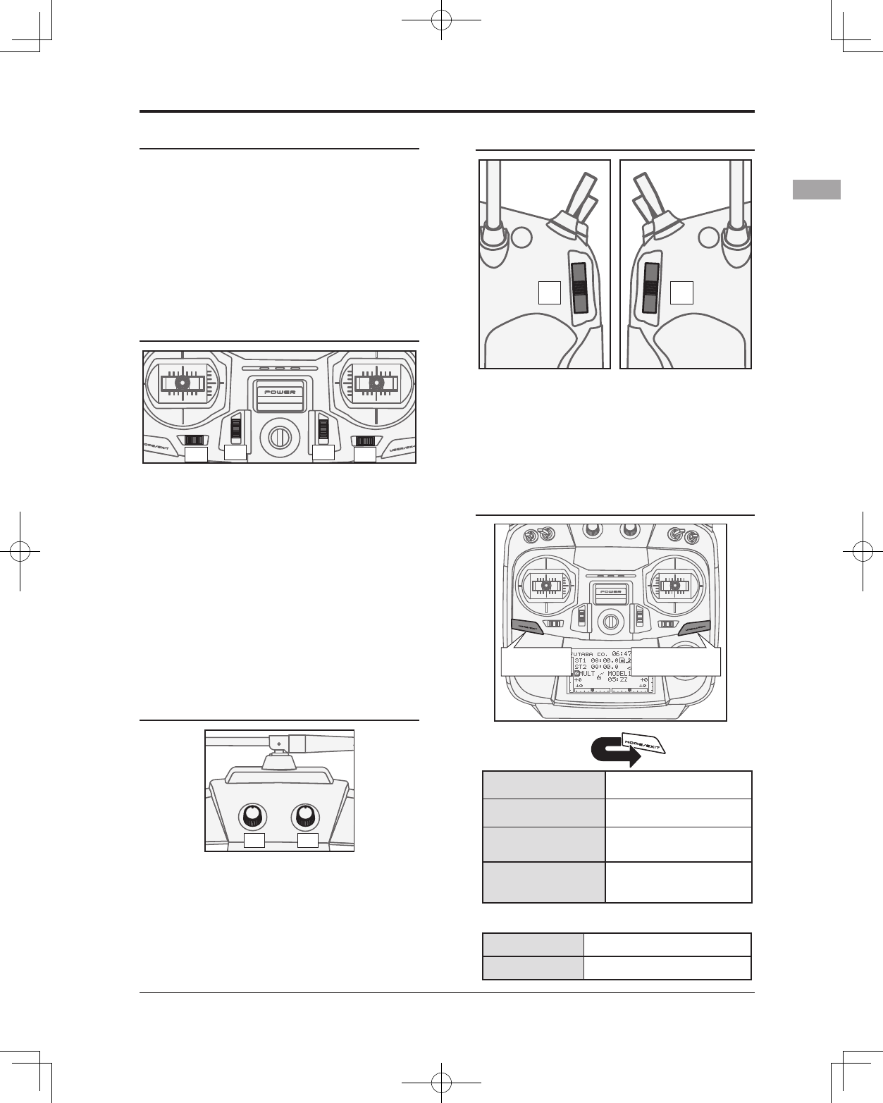
Slide Lever
RSLS
LS (Left), RS (right):
The slide lever LS and RS offer analog input.
*The T14SG transmitter beeps when the lever comes to the
center.
*You can select a slide lever and set the movement
direction on the setting screen of mixing functions.
HOME/EXIT and U.MENU/MON. Button
Volume
LD RD
Volume LD and RD:
The volume LD and RD knobs allow for
analog input.
*The T14SG transmitter beeps when the volume knob
reaches the center position.
*You can use each setting screen of the mixing functions to
select volumes and dene the direction of a movement.
Digital Trim
T1
T2
T3
T4
Digital Trim T1, T2, T3 and T4:
This transmitter is equipped with four (4)
digital trims. Each time you press a trim button,
the trim position moves one step. If you continue
pressing it, the trim position starts to move faster.
In addition, when the trim position returns to
the center, the tone will change. You can always
monitor trim positions by referencing the LCD
screen.
*You can select the trim step amount and the display unit
on the home screen on the T1-T4 setting screen within the
linkage menu.
Note: The trim positions you have set will be stored in the
non-volatile memory and will remain there.
HOME/EXIT
Button
U.MENU/MON.
Button
RETURN
Press Return to the previous
screen
Press and hold Return to the Home
screen
It pushes from HOME
screen. To TELEMETRY display
Push and hold for
one (1) second from
HOME screen. Key lock On or O
Press To SERVO MONITOR display
Press and hold To User Menu display
HOME/EXIT:
U.MENU/MON.:
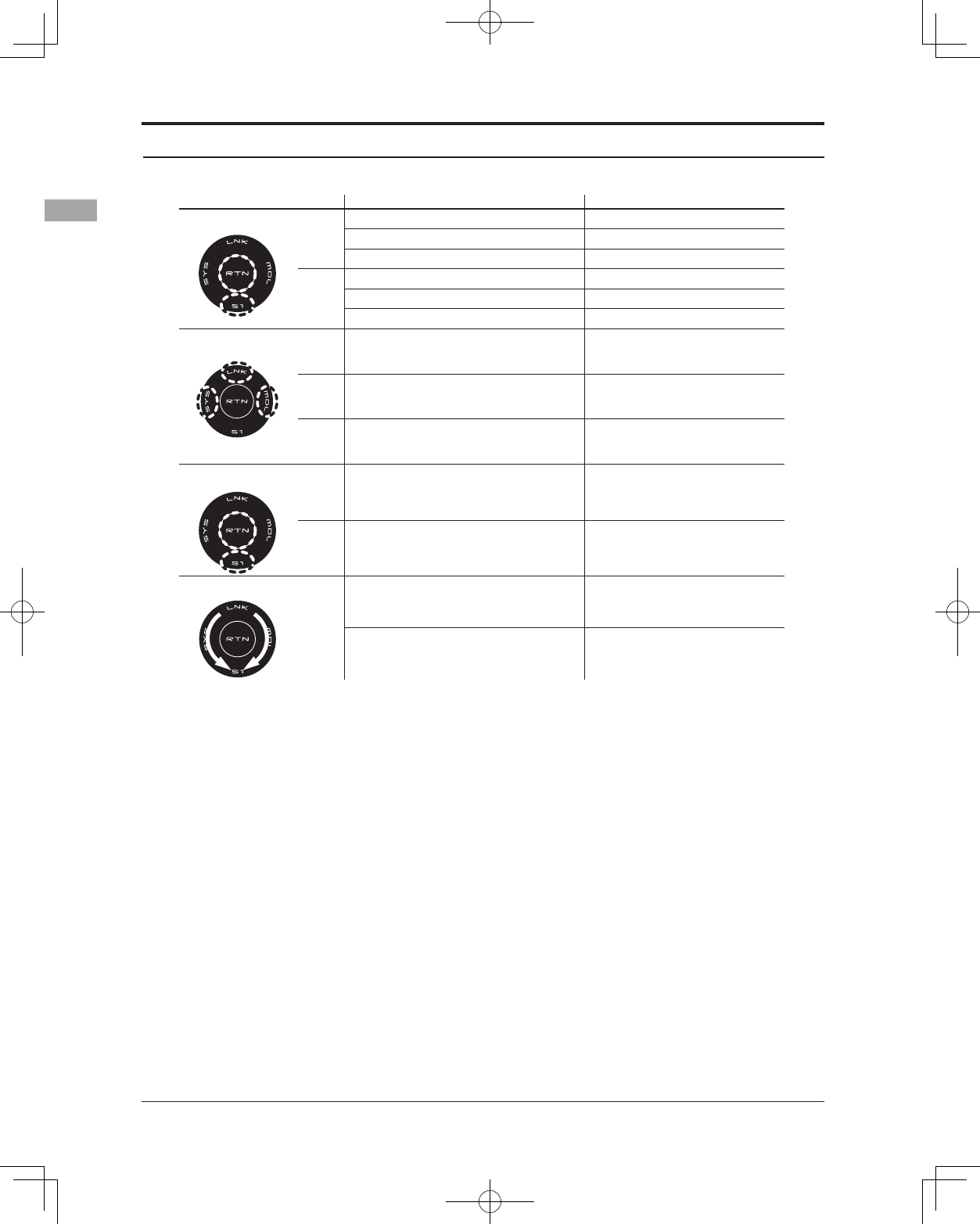
16 <Before Use>
SensorTouch™ operation Condition Working
• Short 'tap'
S1
If the screen has more than one page. (Ex. P-MIX screen)
The cursor moves to the top of next page.
If the screen have only one (1) page. The cursor moves to the top of page.
If inputting data while the cursor is blinking. The input data is canceled.
RTN
At the moving cursor mode. Change to the input data mode.
While in the data input mode. Changes to the moving cursor mode.
While inputting data while cursor is blinking. The data is entered.
• Two short 'taps'
SYS At all screens Jump to System Menu screen directly.
LNK At all screens Jump to Linkage Menu screen directly.
MDL At all screens Jump to Model Menu screen directly.
• Touch and hold for
one (1) second. S1 At the HOME screen Key lock On or Off
RTN While inputting data with no blinking cursor. Reset to the initialized value.
• Scrolling
Outline
of
“RTN”
Lightly circling the outside edge of the RTN button. The cursor moves accordingly.
During the data input mode. Increases or decreases values accordingly.
Touch sensor operation
Data input operation is performed using the touch sensor.
Movement of cursor, value input or mode
selection
:
Movement of the cursor on the menu screen
and movement of the cursor among items on a
setup screen can be controlled by scrolling your
nger to the left and right in the direction of the
arrow in the scrolling diagram above. You can
also go to the next page, if there is a next page.
This scrolling technique is also used for data
input, value input, mode selection, and similar
operations. Examples include: Value, ON, OFF,
INH, ACT, etc.
RTN button:
Touch the RTN button when you want to open
a setup screen or to switch between cursor move
mode (reverse display) and data input mode (box
display).
This button can also be used as the enter button
when a conrmation message is displayed on the
screen, etc.
S1 button:
When there is a next page on a menu screen or
setup screen, you can go to that page by touching
the S1 button. In this case, the cursor moves to
the screen title item of the page.
Exiting setup screen:
To end the operation on a setup screen and
return to the menu screen, move the cursor to the
screen title item and touch the RTN button.
To return to home screen directly, touch the S1
button for 1 second.
Alternatively, move the cursor to the screen
title item and touch the RTN button to return to
the home screen from a menu screen.
17
<Before Use>
Note:
*Scroll operation: Circle your nger on the outside edge of
the RTN button. The sensors may mis-read your touch as
a reverse rotation if the circle is smaller, or performed on
the inside edge of the RTN button.
* The SensorTouch™ may not operate smoothly if your
hand is touching the surrounding case parts. Please make
sure that the tip of your finger is actually operating the
SensorTouch™.
*If the SensorTouch™ does not register your input, please
try again after lightly tapping your finger on the sensor
once again.
* Do not operate the SensorTouch™ while wearing gloves.
The SensorTouch™ may not work correctly.
Caution
The touch sensor may not operate
correctly if spark noise is generated from
a gasoline engine, etc. Please remove the
transmitter to a location away from the
noise source.
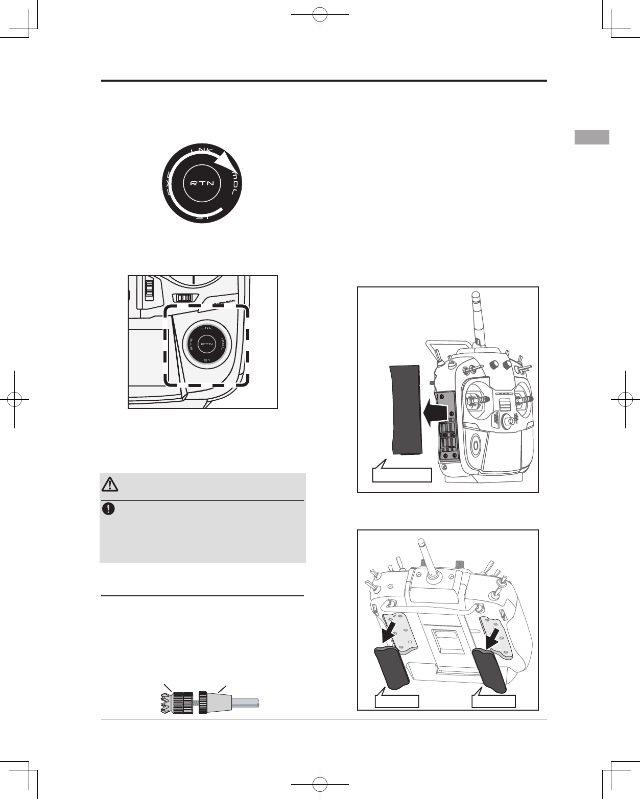
Stick Adjustment
Adjustment of the stick lever length
You can adjust the length of stick levers, as
you like. It is recommended to adjust the length
of the sticks in line with your hand size.
1. Hold the lever head "B" and turn the lever
head "A" counter-clockwise. The lock will
be released.
2. Turn the lever-head "A" clockwise as you
hold the lever-head "B" after placing it as
you like.
A
Lever Head
B
Lever Head
Adjustment of stick lever tension
The tension of the self-return type stick lever
can be adjusted.
1. First, Remove the battery cover on the
bottom of the transmitter. Next, unplug the
battery wire and remove the battery from
the transmitter.
2. Next, using a hand, remove the transmitter's
side cover (rubber). When using Mode 1,
you will need to remove the side cover to
expose the tension screw.
3. Using your hand remove the transmitters
rear rubber grips.
• Side Cover
• It is only the mode 1
•Rear Grip •Rear Grip
18 <Before Use>
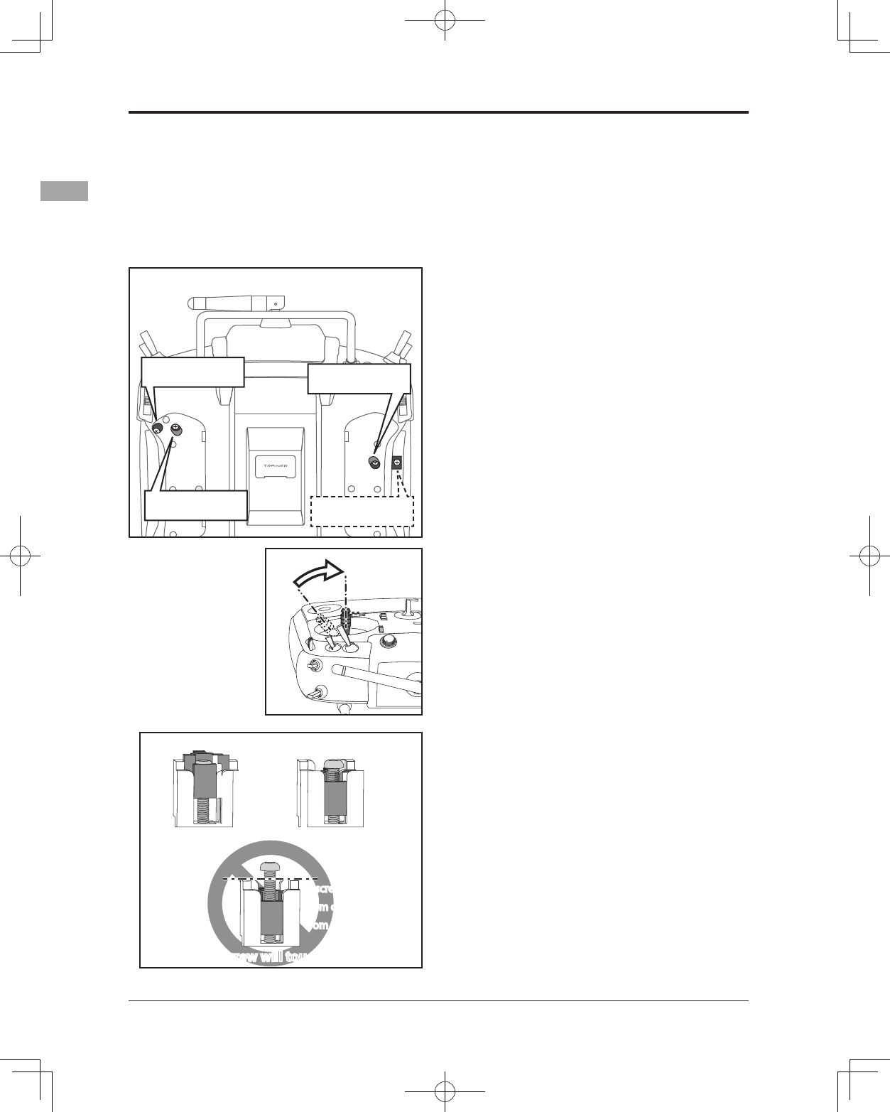
5. At the end of adjustment, re-install the side
cover and rear grips.
4. Use a small Phillips screwdriver to adjust the
spring strength as you prefer by turning the
adjusting screw of the stick you want to
adjust.
*Turning the screw clockwise increases the tension.
CAUTION: If you loosen the screw too
much, it can interfere with the operation of
the sticks internally.
The stick can be
adjusted to how
quickly it returns to
neutral.
+ screw is clockwise.
Stick tension maximum Stick tension minimum
+ screw is counter-clockwise.
A screw is kept
from coming out
from a line.
A screw is kept
from coming out
from a line.
*The screw will touch the case.*The screw will touch the case.
•Stick Tension (J1)
(Mode 1/2)
•Stick Tension (J2)
(Mode 2) •Stick Tension (J4)
(Mode 1/2)
•Stick Tension (J3)
(Mode 1)
19
<Before Use>
SD Card (Secure Digital memory card) (Not
included)
The T14SG transmitter model data can be
stored by using any commonly found SD card.
When T14SG transmitter update software is
released, the software is updated using an SD
card. The T14SG is capable of using SD cards
with a memory size SD : 32MB-2GB SDHC :
4GB-32GB.
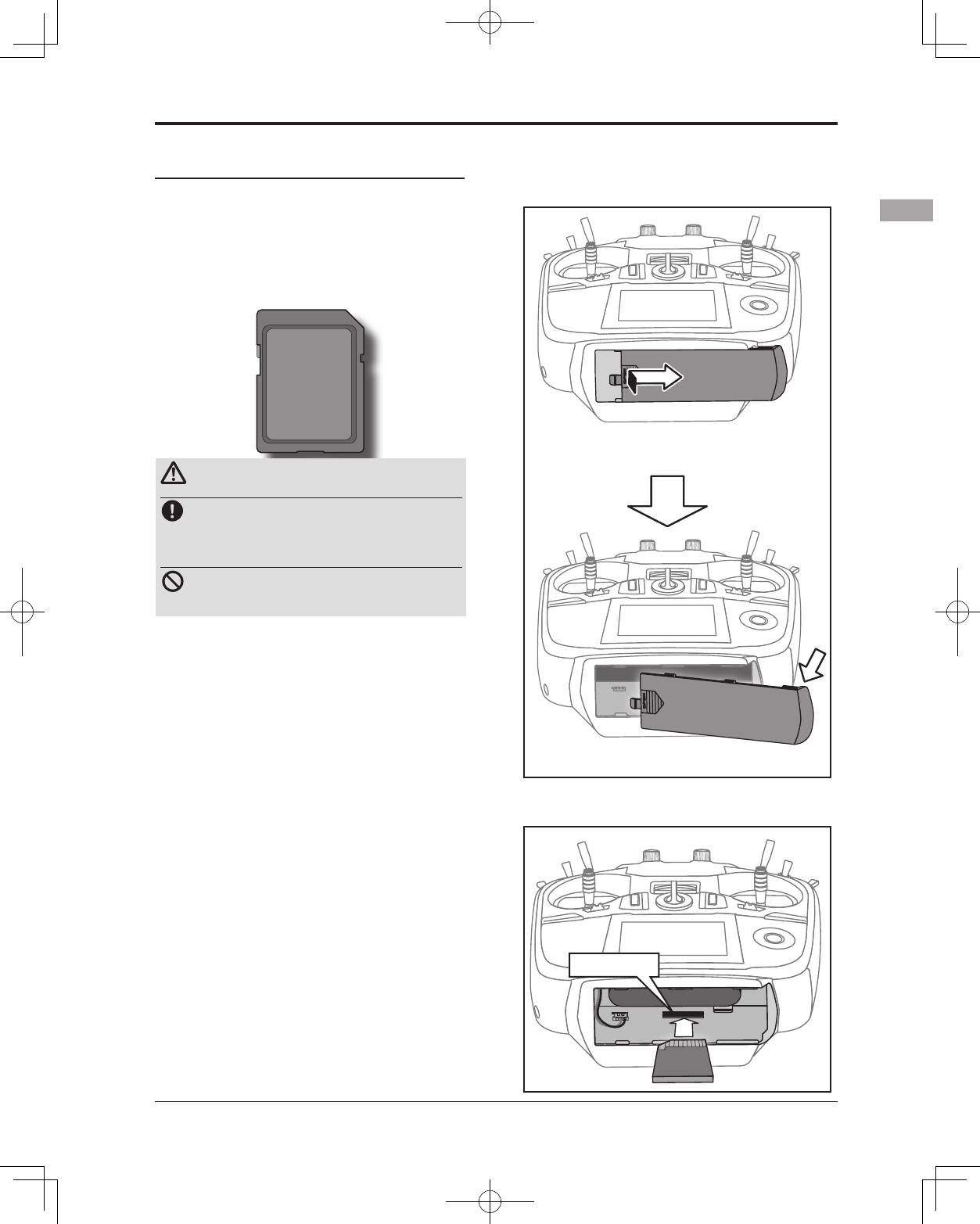
Inserting/removing the SD card
1. Turn off the transmitter power and then
open the battery cover at the bottom of
the transmitter.
2. The SD card slot is show here in the gure
below.
Caution
Be sure to turn off the power to the
transmitter before inserting or removing
the SD card.
As the SD card is a precision device, do
not use excessive force when inserting.
Restrictions when using an SD card
The following restrictions apply when using an
SD card:
*The SD card must first be initialized using the T14SG
dedicated format. The SD card cannot be used as is
without formatting to the T14SG.
*Initializing destroys all the data previously saved on the
card.
*An SD card formatted to the T14SG cannot be written
directly from a PC by Windows Explorer, etc. The les
must be converted and written by the Futaba File System
software. Files are identied by number instead of name.
This special conversion software can be downloaded from
Futaba's web site at:
http://www.futaba-rc.com/software-updates.html
① Push to open.
②Slide in the direction of the
arrow on the battery cover.
③ Battery cover will open downward.
SD card slot
20 <Before Use>
[Inserting the card]
Turn the SD card so that the front of the
card faces the rear of the transmitter and
slide the card into the card slot.
*Push in the card until it is rmly seated in the card slot.
[Removing the card]
When the SD card is pressed in once again,
the card will be released from the card
slot. and can be removed.
3. Close the battery cover.
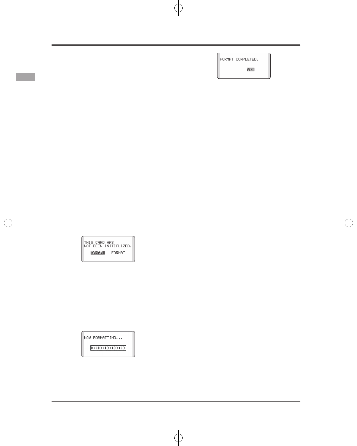
SD card initialization
To use an SD card with the T14SG, the card
must rst be formatted. Once formatted, the card
does not have to be reformatted. Formatting is
performed by the T14SG.
[IMPORTANT] When an SD card is formatted
for the T14SG, all pre-existing data is
destroyed. Do not format a card containing
important data.
[Formatting procedure]
1. Insert the SD card into the SD card slot of
the T14SG.
2. Turn on the T14SG power. When an
unformatted card is inserted into the T14SG,
the screen shown below appears.
3. If the T14SG is ready to format, move the
cursor to [FORMAT] and touch the RTN
button. (To cancel formatting, move the
cursor to [CANCEL] and touch the RTN
button.)
4. Move the cursor to [YES] and touch the RTN
button.
* Formatting starts. During formatting, the [NOW
FORMATTING...] message is displayed.
*When formatting is completed, The [FORMAT
COMPLETED] message is displayed. Depending on the
card capacity and speed, formatting may take as long as
several minutes.
[IMPORTANT] Do not turn off the power until
the [FORMAT COMPLETED] message is
displayed.
5. End formatting by touching the RTN button.
SD card reader/writer
Saving model data and update files (released
from Futaba) to the SD card from your own
PC, you can transfer those file to your T14SG
transmitter. Equipment for reading and writing
SD cards is available at most electronics stores.
Stored data
If you have a problem saving or reading data
after a long period of use, we suggest obtaining a
new SD card to avoid further difculties.
*Futaba is not responsible for compensating any failure or
damage to the data stored in the memory card. As such,
we suggest that you maintain a backup of your important
data contained on your SD card.
21
<Before Use>
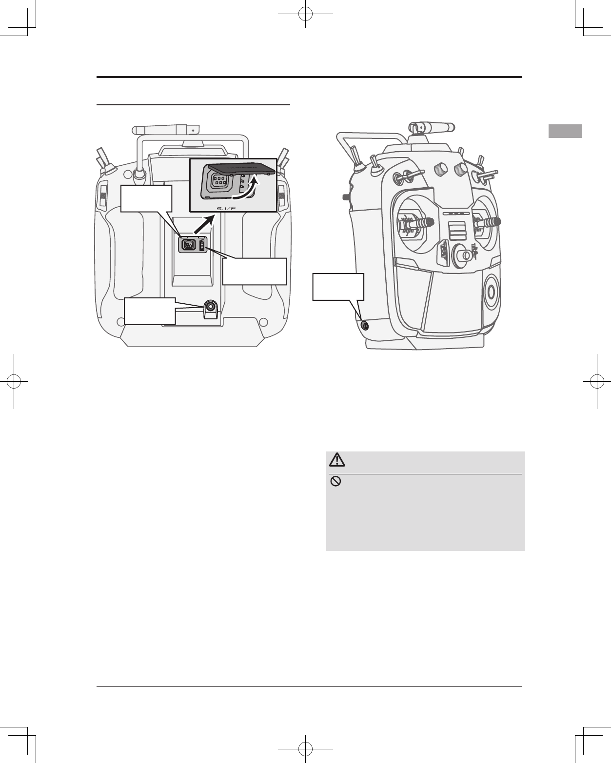
Connector/Plug
Connector for trainer function
When you use the trainer function, connect the
optional trainer cable between the transmitters
for teacher and student.
*You can set the trainer function on the Trainer Function
screen in the System menu.
S.BUS connector (S.I/F)
When setting an S.BUS servo and telemetry
sensor, connect them both here.
(Supply power by 3-way hub or Y-harnesses.)
Earphone plug
It is not used now. (The function after upgrade)
Warning
Do not connect any other chargers except
the special charger to this charging
connector.
*If you take out the NiMH battery HT5F1800B from the
transmitter, you can use the optional quick charger CR-
2000 corresponding to NiMH battery.
Trainer
Connector
S.BUS (S.I/F)
Connector
Earphone
Plug
Connector for battery charger
This is the connector for charging the NiMH
battery HT5F1800B that is installed in the
transmitter. Do not use any other chargers except
the attached special charger corresponding to
NiMH battery.
Charge
Plug
22 <Before Use>
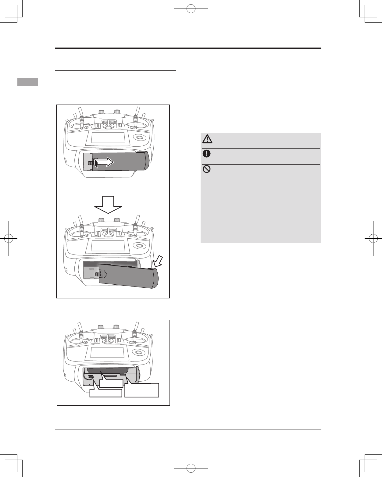
Installation and Removal of the HT5F1800B
Transmitter Battery
Attachment of the battery
1. Slide the battery cover on the bottom of
the transmitter toward the right side and
open it.
2. Install the battery in the holder.
3. Connect the battery connector.
4. Close the battery cover completely.
Battery Removal
Note: If you remove the battery while the
power is on, the data you have set will not
be saved.
1. Open the battery cover.
2. Disconnect the battery connector.
3. Press on the battery release tab and pull
the battery downwards to remove.
4. Close the battery cover completely.
Warning
Be careful not to drop the battery.
Never disconnect the battery connector
from the T14SG transmitter after
turning off the power until the screen is
completely blank and the transmitter has
shut down completely.
* Internal devices such as memories may be damaged.
* If there is any problem, the message "Backup Error"
will be shown the next time when you turn on the
power of the transmitter. Do not use the transmitter as
it is. Send it to the Futaba Service Center.
① Push to open.
②Slide in the direction of the
arrow on the battery cover.
③ Battery cover will open downward.
Battery Battery
release tab
Connector
23
<Before Use>
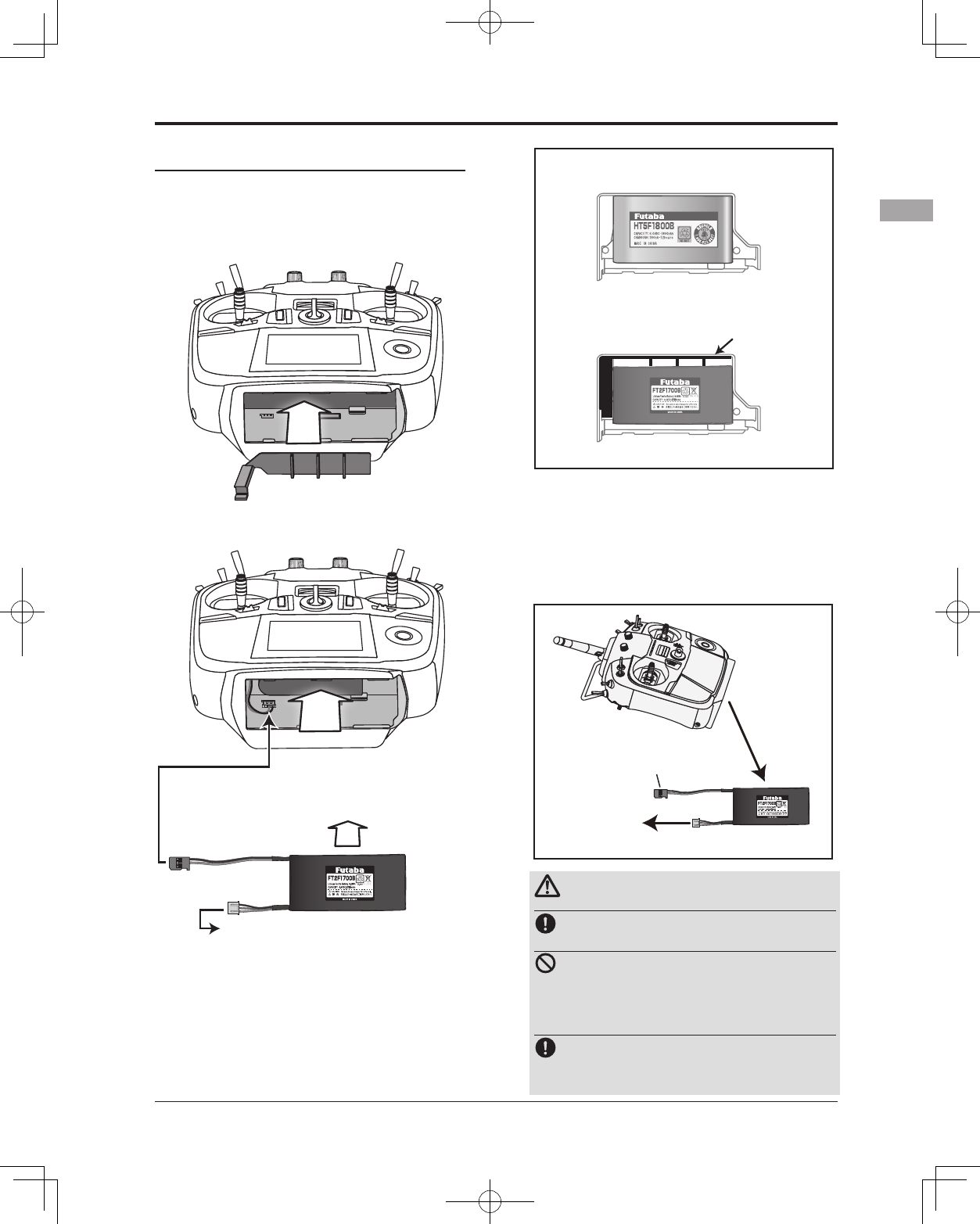
When exchanging for the LiFe battery
(FT2F2100B/FT2F1700B) of an option.
Attachment of the battery
1. T14SG to HT5F1800B is removed.
2. A LiFe spacer (14SG attachment) is
inserted as shown in a gure.
3. A LiFe battery (option) is inserted as shown
in a gure.
4.2P connector of a LiFe battery is
connected.
5. Close the battery cover completely.
6.T14SG is turned on and [LINKAGE
MENU]=>[WARNING]=>[LOW BATTERY] is
called.
7. It changes into 6.0V from 5.6V.
Charge of a LiFe battery
Note: LiFe battery cannot be charged with the
charger of 14SG attachment.
Be sure to remove a battery from T14SG and
to charge from the charger only for LiFe.
Warning
Follow the manual of a LiFe battery.
Don't charge the LiFe battery with the
NiMH charger of 14SG attachment.
* Be sure to remove from T14SG and to charge with the
charger only for LiFe.
Be sure to change the voltage of LOW
BATTERY WARNING into 6.0V from
5.6V
LiFe SPACER
LiFe
Battery
The balance charge connector is not connected
in the state where the battery is set to a transmitter.
A LiFe
battery is
removed
from T14SG.
Balance charge
is carried out from the charger only for LiFe.
2P connector is
removed from T14SG.
The battery state inside T14SG
NiMH HT5F1800B
LiFe FT2F2100B/1700B
LiFe SPACER
*About low battery voltage, all the models included in
one transmitter are changed in common. It cannot set to
different voltage for every model. Moreover, data reset is
not carried out.
24 <Before Use>
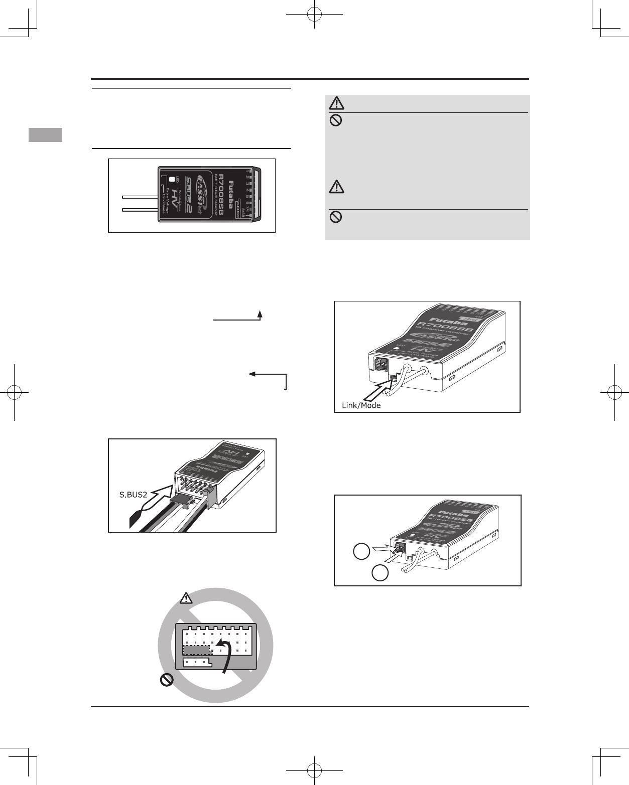
Link/Mode Switch
Use the small plastic screw driver that was
included with your receiver.
The Link/Mode Switch is also used for the CH
mode selection.
Extra Voltage Connector
Use this connector when using a voltage
telemetry device to send the battery voltage (DC0
~ 70V) from the receiver to the transmitter.
You will need to purchase the optional External
Voltage input cable (CA-RVIN-700) FUTM5551.
You can then make a cable with an extra
connector to the External voltage connector.
Receiver nomenclature
Before using the receiver, be sure to read the
precautions listed in the following pages.
Receiver R7008SB
Connector
"1 through 6": outputs for the channels 1
through 6
"7/B": outputs of 7 channels and power.
"8/SB": outputs of 8 channels or S.BUS port.
[S.BUS Servo S.BUS Gyro ]
*When using 8/SB as S.BUS, you have to set
CH MODE of the following page to mode B or
mode D.
"S.BUS2": outputs of S.BUS2 port.
[S.BUS2 Servo S.BUS2 Gyro Telemetry Sensor ]
*When using 9 or more channels, use an S.BUS
function or use a second R7008SB and link both
to your transmitter.
Connector insertion
Firmly insert the connector in the direction
shown in the gure. Insert the S.BUS2 by turning
it 90 degrees.
+
−
Do not connect either a switch
or battery in this manner.
Receiver
Danger
Danger
Don't connect a connector, as shown in a
before gure.
*It will short-circuit, if it connected in this way. A short
circuit across the battery terminals may cause abnormal
heating, re and burns.
Warning
S.BUS2 connectors
Don't connect an S.BUS servo / gyro to
S.BUS2 connector.
LED Monitor
This monitor is used to check the CH mode of
the receiver.
25
<Before Use>
R7008SB CH Mode
The R7008SB receiver is a very versatile
unit. It has 8 PWM outputs, S.BUS and S.BUS2
outputs. Additionally the PWM outputs can be
changed from channels 1-8 to channels 9-14. If
you only desire to use it as an 8 channel receiver
(without S.BUS), it can be used without any
setting changes.
The T14SG has the ability to link to two
R7008SB receivers. One of them outputting
channels 1-8 and the other outputting channels
9-14 giving you 14 PWM channels. Instructions
for this configuration and S.BUS operation
follow.
[How to change the R7008SB Channel mode.]
1. Press and hold down the Link/Mode button
on the R7008SB receiver.
2. Turn the receiver on while holding down
the Link/Mode button. when the LED
begins to blink green/red the button may
be released.
3. The LED should now be blinking red in one
of the patterns described by the chart
below.
4. Each press of the Mode/Link button
advances the receiver to the next mode.
5. When you reach the mode that you wish
to operate in, press and hold the Mode/
Link button for more than 2 seconds.
6. Once locked into the correct mode the
LED will change to a solid color.
7. Please cycle the receiver(s) power off and
back on again after changing the Channel
Mode.
Receiver connector
Setting channel
Mode A
1 ~ 8CH
Mode B
1 ~ 7CH
Mode C
9 ~ 14CH
Mode D
9 ~ 14CH
1 1199
2 2 2 10 10
3 3 3 11 11
4 4 4 12 12
5 5 5 13 13
6 6 6 14 14
7/B 7 7 - -
8/SB 8 S.BUS - S.BUS
Red LED blink 1time 2time 3time 4time
R7008SB CH MODE TABLE
Danger
Don't touch wiring.
* There is a danger of receiving an electric shock.
Do not short-circuit the battery terminals.
* A short circuit across the battery terminals may cause
abnormal heating, re and burns.
Please double check your polarity ( +and
-) when hooking up your connectors.
* If + and - of wiring are mistaken, it will damage,
ignite and explode.
Don’t connection to Extra Voltage before
turning on a receiver power supply.
26 <Before Use>
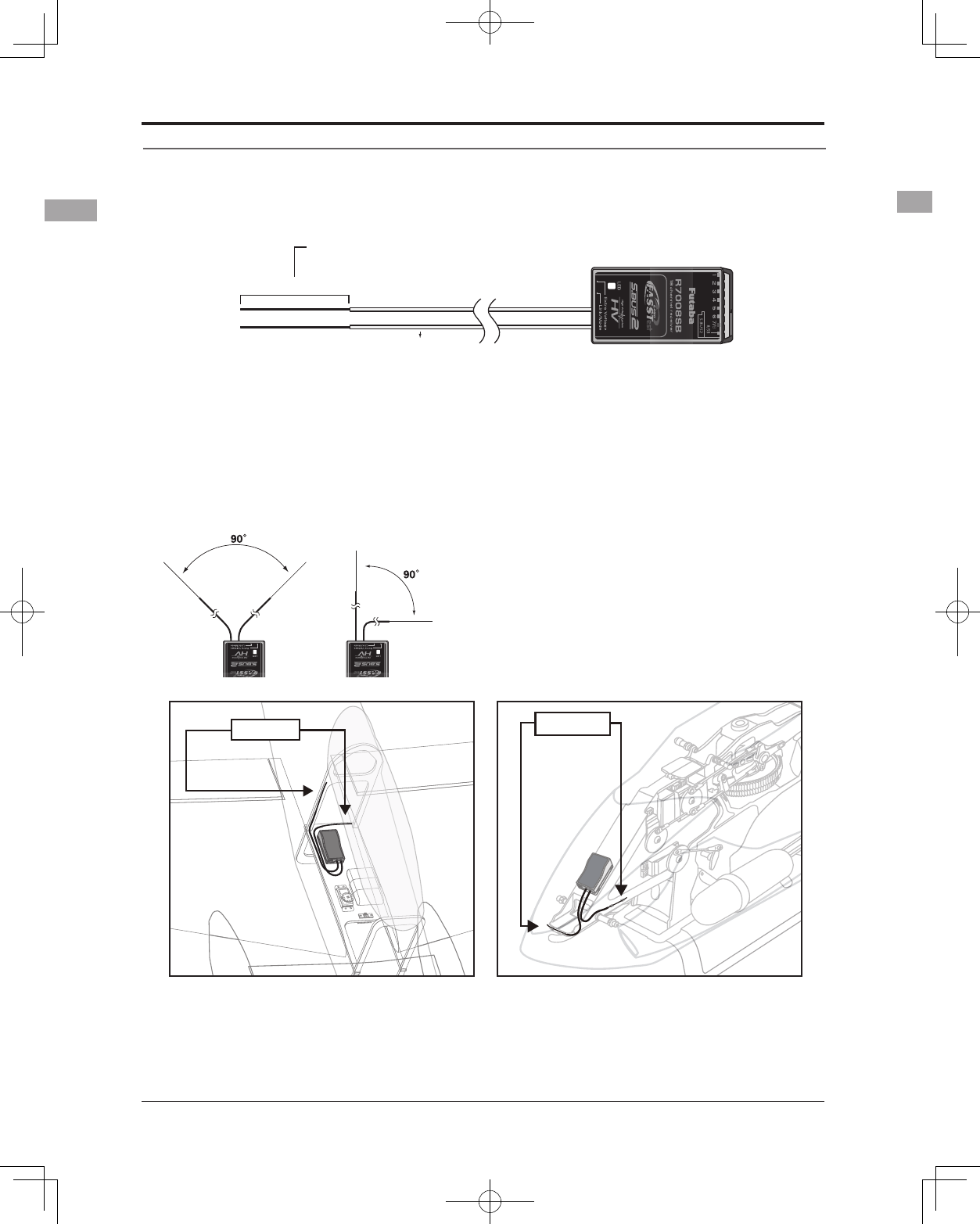
Receiver's Antenna Installation
The R7008SB has two antennas. In order to maximize signal reception and promote safe modeling Futaba
has adopted a diversity antenna system. This allows the receiver to obtain RF signals on both antennas and
y problem-free.
Antenna
*Must be kept as straight as possible.
Coaxial cable
R7008SB Receiver
To obtain the best results of the diversity
function, please refer to the following
instructions:
1. The two antennas must be kept as straight
as possible. Otherwise it will reduce the
effective range.
2. The two antennas should be placed at 90
degrees to each other.
This is not a critical figure, but the most
important thing is to keep the antennas
away from each other as much as possible.
Larger models can have large metal
objects that can attenuate the RF signal. In
this case the antennas should be placed
at both sides of the model. Then the best
RF signal condition is obtained at any ying
attitude.
3. The antennas must be kept away from
conductive materials, such as metal,
carbon and fuel tank by at least a half
inch. The coaxial part of the antennas does
not need to follow these guidelines, but do
not bend it in a tight radius.
4. Keep the antennas away from the motor,
ESC, and other noise sources as much as
possible.
*The two antennas should be placed at 90 degrees to each other.
*The Illustration demonstrates how the antenna should be placed.
*Receiver Vibration and Waterproofing: The receiver contains precision electronic parts. Be sure to avoid vibration,
shock, and temperature extremes. For protection, wrap the receiver in foam rubber or other vibration-absorbing
materials. It is also a good idea to waterproof the receiver by placing it in a plastic bag and securing the open end of the
bag with a rubber band before wrapping it with foam rubber. If you accidentally get moisture or fuel inside the receiver,
you may experience intermittent operation or a crash. If in doubt, return the receiver to our service center for service.
Antenna Antenna
27
<Before Use>
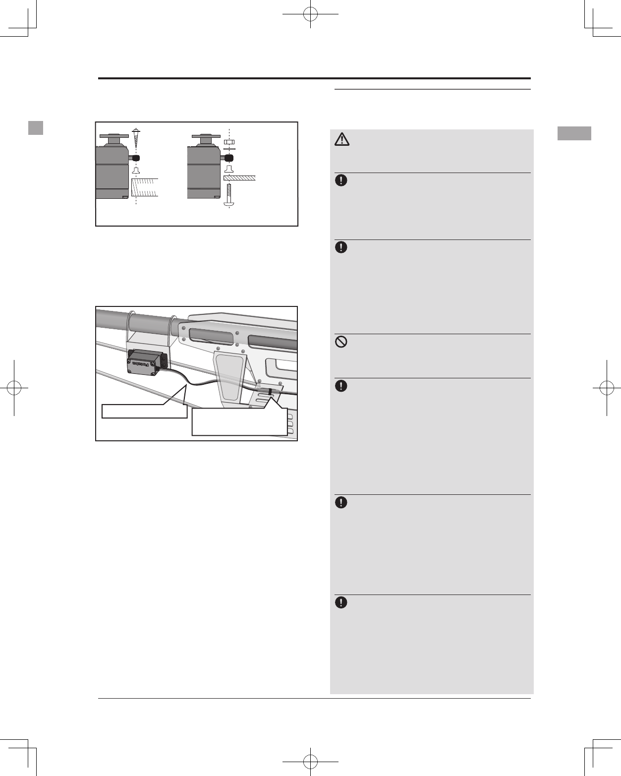
Rubber
grommet
Brass eyelet
Wood screw
Servo mount
2.3-2.6mm nut
washer
Rubber
grommet
Brass eyelet
Servo mount
2.3-2.6mm screw
(Helicopter) (Airplane/Glider)
Servo lead wires
To prevent the servo lead cable from being
broken by vibration during flight, provide a
little slack in the cable and fasten it at suitable
points. Periodically check the cable during daily
maintenance.
Fasten about 5-10cm
from the servo outlet so
that the lead wire is neat.
Margin in the lead wire.
Mounting the power switch
When mounting a power switch to an airframe,
make a rectangular hole that is a little larger than
the total stroke of the switch so that you can turn
the switch ON/OFF without binding.
Avoid mounting the switch where it can be
covered by engine oil and dust. In general, it is
recommended to mount the power switch on the
side of the fuselage that is opposite the mufer.
Safety precautions when you install
receiver and servos
Warning
Connecting connectors
Be sure to insert the connector until it
stops at the deepest point.
How to protect the receiver from vibration
and water
Wrap the receiver with something soft
such as foam rubber to avoid vibration.
If there is a chance of getting wet, put the
receiver in a waterproof bag or balloon to
avoid water.
Receiver's antenna
Never cut the receiver's antenna. Do not
bind the receiver's antenna with the cables
for servos.
Locate the receiver's antenna as far as
possible from metals or carbon fiber
components such as frames, cables, etc.
*Cutting or binding the receiver's antenna will reduce the
radio reception sensitivity and range, and may cause a
crash.
Servo throw
Adjust your system so that pushrods will
not bind or sag when operating the servos
to the full extent.
*If excessive force is continuously applied to a servo, the
servo could be damaged due to force on the gear train
and/or power consumption causing rapid battery drain.
Mounting servos
Use a vibration-proof rubber (such as
rubber grommet) under a servo when
mounting the servo on a servo mount. And
be sure that the servo cases do not touch
directly to the metal parts such as servo
mount.
*If the servo case contacts the airframe directly, vibration
will travel to and possibly damage the servo.
Mounting the Servo
28 <Before Use>
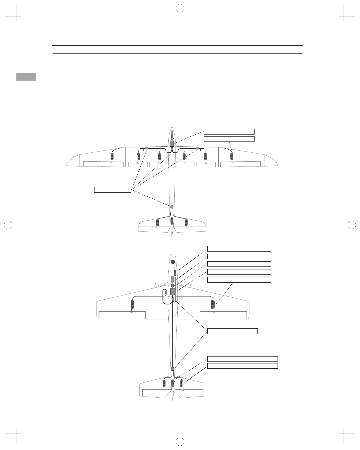
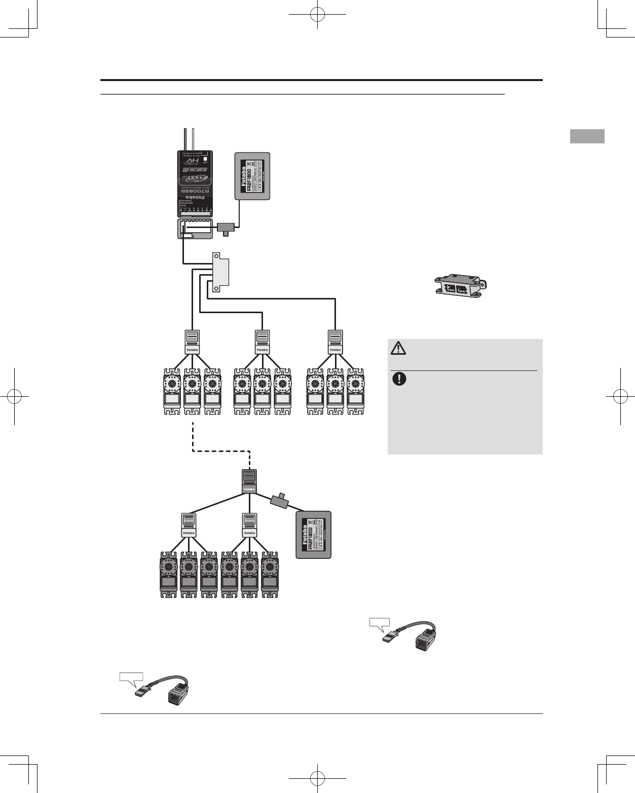
S.BUS/S.BUS2 Installation
This set uses the S.BUS/S.BUS2 system. The wiring is as simplied and clean mounting as possible, even
with models that use a large number of servos. In addition, the wings can be quickly installed to the fuselage
without any erroneous wiring by the use of only one simple wire, even when there are a large number of
servos used.
●When using S.BUS/S.BUS2, special settings and mixes in your transmitter may be unnecessary.
●The S.BUS/S.BUS2 servos memorize the number of channels themselves. (Settable with the T14SG)
●The S.BUS/S.BUS2 system and conventional system (receiver conventional CH used) can be mixed.
Receiver: R7008SB
Battery: FR2F1800 ( Optional )
Switch: HSW-L
Throttle servo: BLS173SV ( Optional )
Aileron servo: BLS174SV×2 ( Optional )
Elevator servo: BLS173SV×2 ( Optional )
Rudder Servo: BLS175SV×1 ( Optional )
HUB×3 ( Optional )
Receiver: R7008SB
Servo: S3172SV×9 ( Optional )
HUB×4 ( Optional )
S.BUS Glider usage example
S.BUS Aerobatic plane usage example
29
<Before Use>
S.BUS Wiring example
Battery
Battery
GY520
Extension
cord
Switch
Switch
Terminal box
HUB
HUB HUB
HUB HUB
HUB
HUB
(Another power supply)
HUB
S.BUS Servo
S.BUS Servo
Receiver
●S.BUS Servo
Since the channel number is memorized by
the S.BUS itself, any connector can be used.
When the SBD-1 (sold separately) is used,
ordinary servos can be used with the
S.BUS system.
●When separate power supply used
When a large number of servos are used or
when high current servos are used, the servos
can be driven by a separate power supply by
using a separate Power Supply 3-way Hub.
●Terminal box
Four connectors can be inserted
Three connectors can be
inserted.
Used when using a separate
power supply battery.
S.BUS
Port
(8/SB)
Orange
Green
*When using 8/SB as S.BUS, you must set the receiver to
Mode B or Mode D. See Mode Chart page 25.
Warning
Power supply
Please make sure that you
use a battery that can deliver
enough capacity for the
number and kind of servos
used. Alkaline batteries
cannot be used.
30 <Before Use>
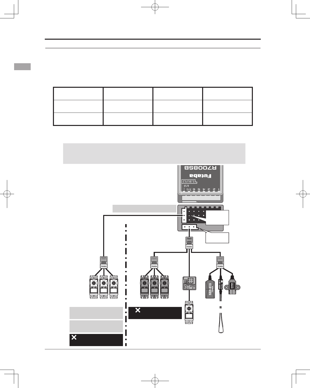
S.BUS2 System
When using the S.BUS2 port, an impressive array of telemetry sensors may be utilized.
Receiver port S.BUS Servo
S.BUS Gyro
S.BUS2 Servo
S.BUS2 Gyro Telemetry sensor
S.BUS ○ ○ ×
S.BUS2 × (※) ○ ○
S.BUS2 TABLE
(※)Don't connect S.BUS Servo,
S.BUS Gyro to S.BUS2 connector.
S.BUS2
Port
S.BUS
Port
(8/SB)
Hub
Hub Hub Hub
Rudder Servo
S.BUS2 ServoS.BUS Servo
S.BUS2 servo
Connection is possible
S.BUS2 gyro
Connection is possible
S.BUS servo
Connection is impossible
Telemetry sensor
Connection is impossible
S.BUS2
GYRO
CH Mode is set to ModeB [D].
+
Telemetry
Sensor
S.BUS servos and gyros and S.BUS2 servos and gyros must be used in the
correct receiver ports. Please refer to the instruction manual to make sure
you connect to the correct one.