Contents
- 1. User Manual 1
- 2. User Manual 2
- 3. User Manual 3
User Manual 2
31
<Before Use>
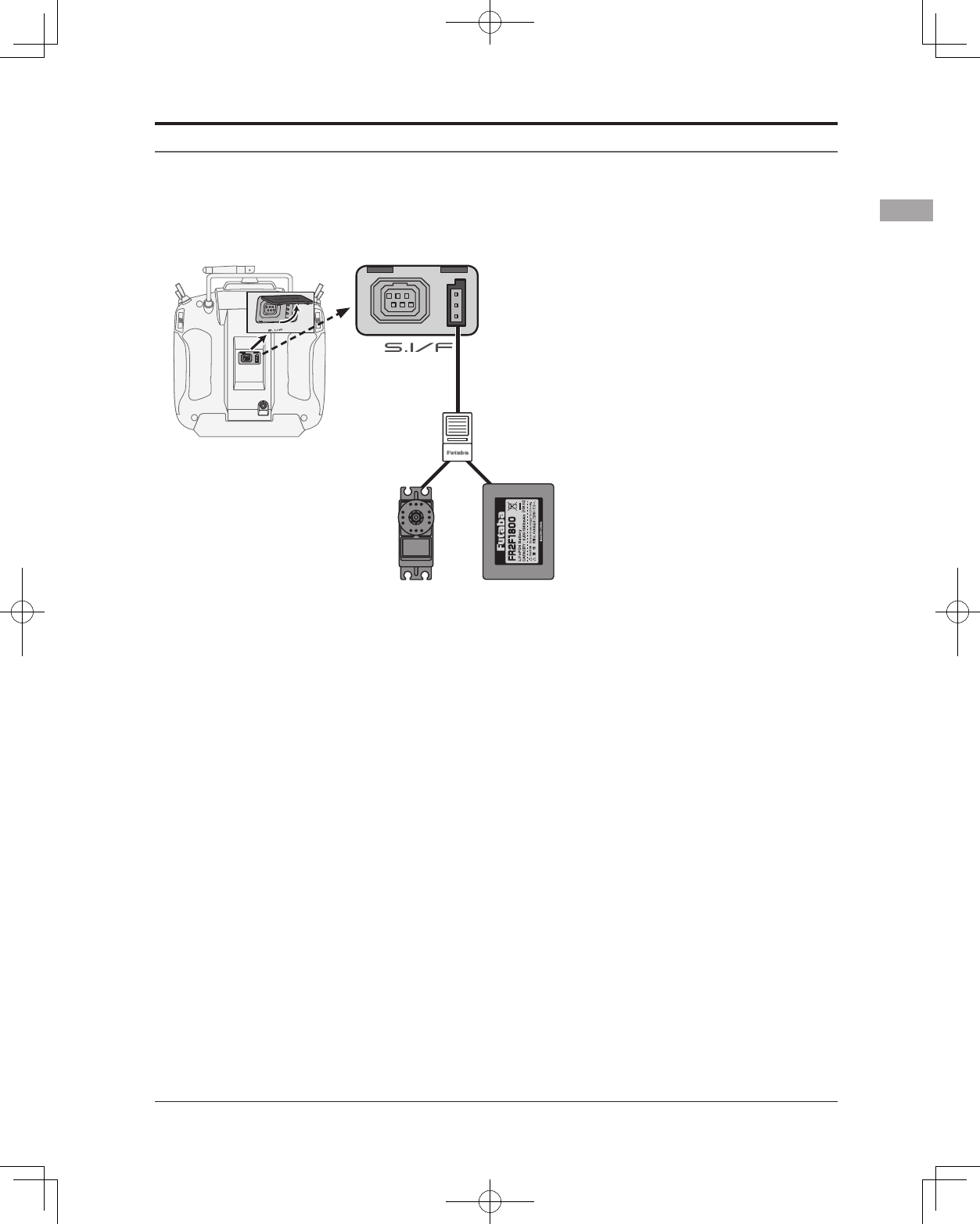
S.BUS/S.BUS2 device setting
S.BUS/S.BUS2 servos or a telemetry sensor can be connected directly to the T14SG. Channel setting and
other data can be entered for the S.BUS/S.BUS2 servos or sensors.
3-way hub
or Y-harnesses
(S.BUS/S.BUS2
Servo)
S.BUS/S.BUS2
device
(Telemetry sensor)
Receivers
Battery
T14SG
1. Connect the S.BUS device and battery you
want to set with a 3-way hub or Y-harnesses
as shown in the gure.
2. Turn on the transmitter power.
3. Call the setup screen.
Servo: System Menu → S.BUS Servo
Sensor: Linkage Menu → Sensor
4. Perform setting in accordance with each
screen.
5. This sets the channel and other data for each
S.BUS servo, or telemetry device to be used
with the S.BUS device or receiver.
32 <Before Use>
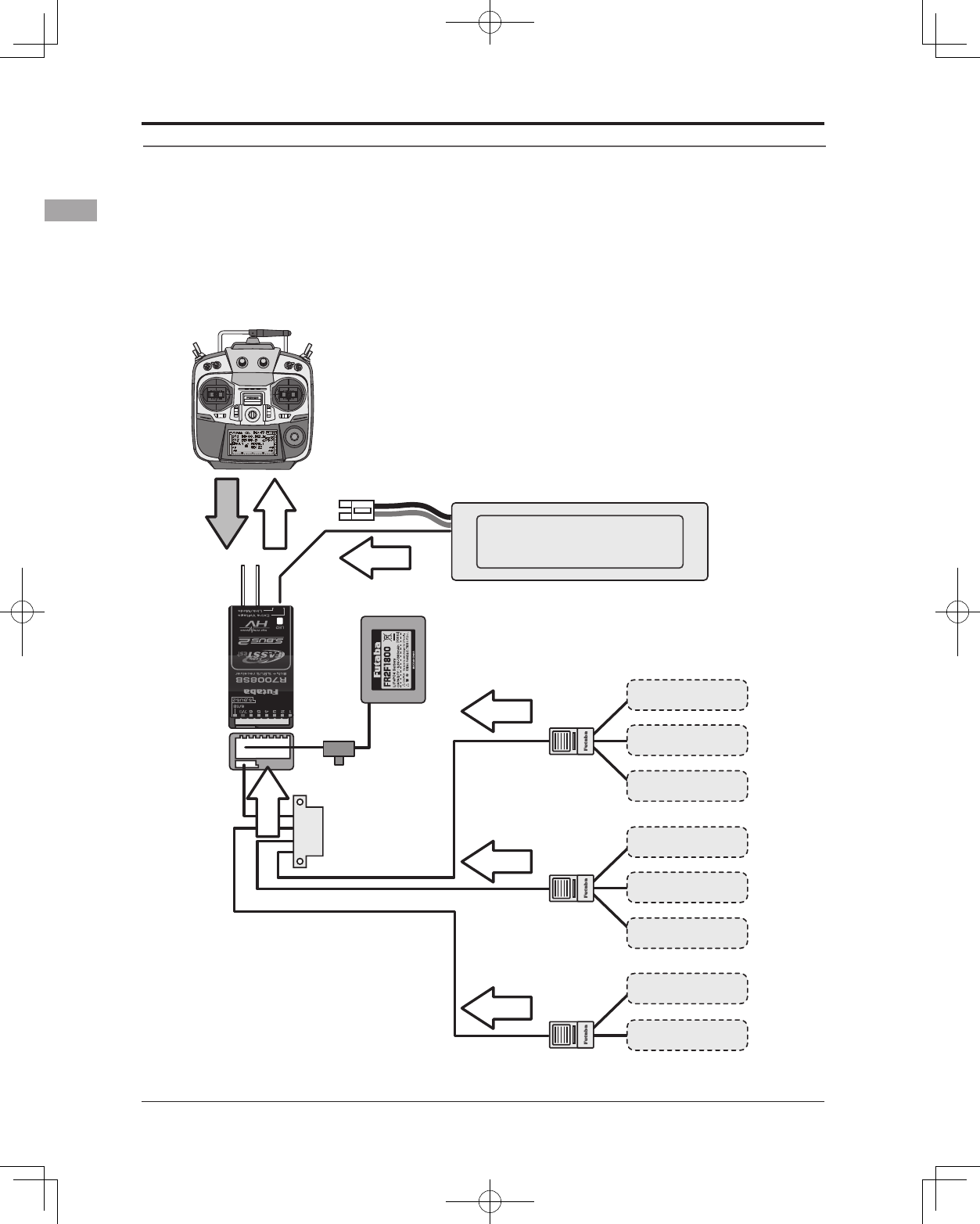
Telemetry System
The R7008SB receiver features bi-directional communication with a FASSTest Futaba transmitter using
the S.BUS2 port. Using the S.BUS2 port an impressive array of telemetry sensors may be utilized. It also
includes both standard PWM output ports and S.BUS output ports.
* Telemetry is available only in the FASSTest 14CH mode. (12CH mode displays only Receiver battery
voltage and Extra battery voltage.)
* The telemetry function requires the corresponding receiver (R7008SB).
* The T14SG will enter and keep the ID number of the R7008SB that it is linked to.
S.BUS2
Connector
Temperature
Sensor Slot 1
Slot 2
Slot 3 ∼ 5
Slot 6
Slot 7
Slot 8 ∼ 15
Slot 16
Receiver
Battery voltage is
displayed at the transmitter.
Drive battery voltage is
displayed at the transmitter.
Switch
T14SG
Terminal box
HUB
HUB
HUB
Info
Info
Info
Info
Info
voltage
Signal
RPM
Sensor
Altitude
Sensor
Voltage
Sensor
GPS
Sensor
Slot 17
***Sensor
***Sensor
***Sensor
●Telemetry sensor (sold separately)
Your aircrafts data can be checked in the
transmitter by connecting various telemetry
sensors to the S.BUS2 connector of the
receiver.
●Slot No.
Servos are classified by channel, but sensors
are classified by “slot” . Since the initial slot
No. of the T14SG is preset at each sensor,
the sensors can be used as is by connecting
them. There are 131 slots.
Info
33
<Basic Operation>
BASIC OPERATION
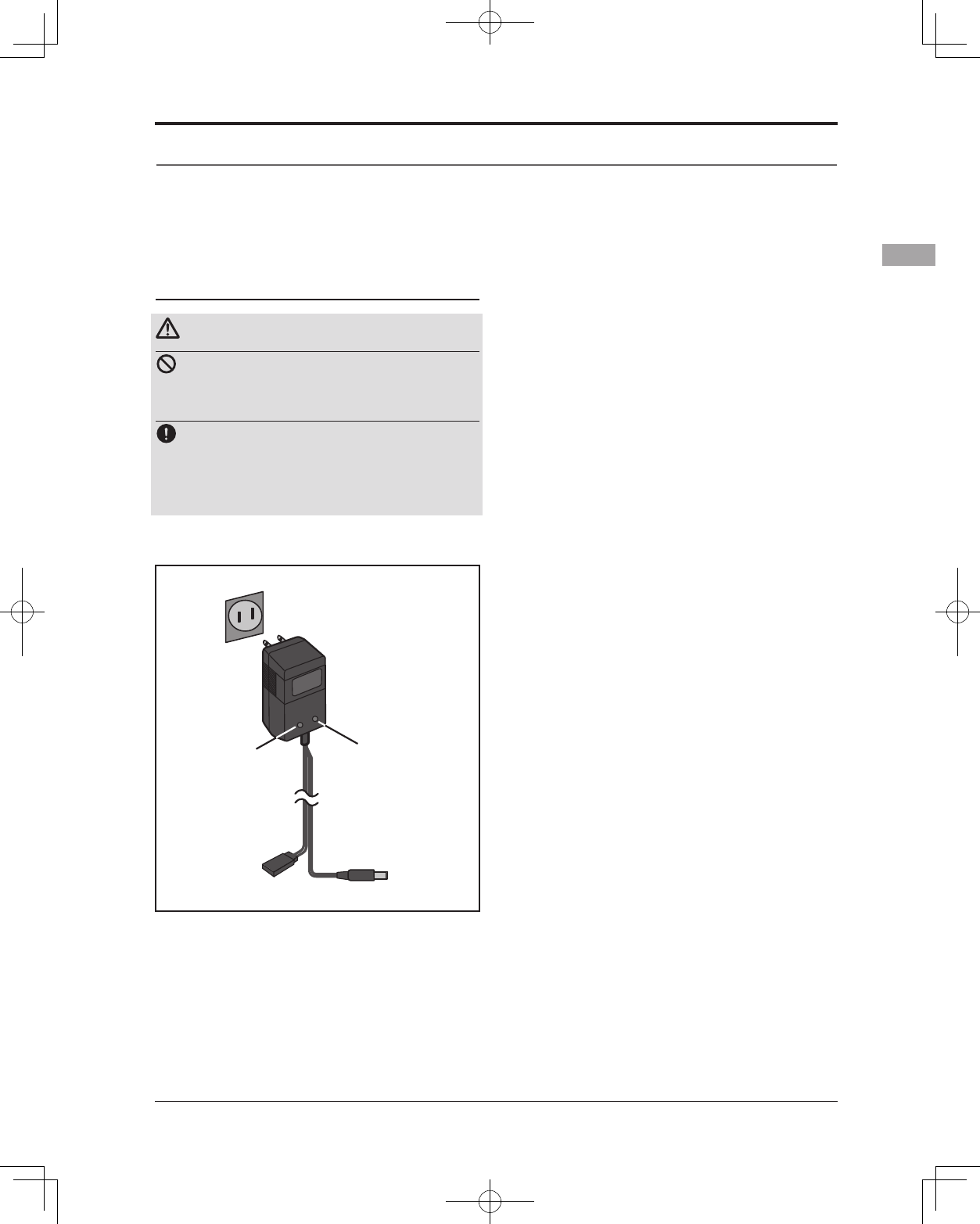
How to charge the NiMH battery HT5F1800B
for the transmitter
Danger
The NiMH battery HT5F1800B is only for
your T14SG. Do not use this battery for other
equipment.
Be sure to use the attached special charger to
charge the battery.
*If you take the NiMH battery HT5F1800B out of the
transmitter, you can use the optional quick charger CR-2000
corresponding to NiMH battery.
[Method of charging battery]
*Connect to AC outlet
specified.
●Special charger
Receiver Batt.
Charging display
To T14SG charge
connector
Transmitter Batt.
Charging display
1. Connect the special charger to the wall
socket (AC outlet).
2. Connect the connectors to the T14SG
charging jack.
*Conrm that the charging indicator, LED lamp, is on.
*Turn off the transmitter while charging the battery.
3. Remove the battery after 15 hours.
*Battery charging will not automatically stop. Remove the
battery and transmitter from the charger and remove the
charger from the wall socket.
*It is recommended to reactivate the battery by cycling
several times if the battery has not been used for a long
period.
*In the case of NiMH/NiCd batteries, you may find poor
performance of the battery if you have used the battery
only for a short period or if you repeat charging while the
battery is not fully discharged. It is suggested to discharge
the battery to the recommended level after use. It is also
recommended to charge the battery just before use.
Battery Charging
Before charging batteries, read the "Cautions for handling battery and battery charger" in the section
"NiMH/NiCd Battery Safety and Handling Instructions".
34 <Basic Operation>
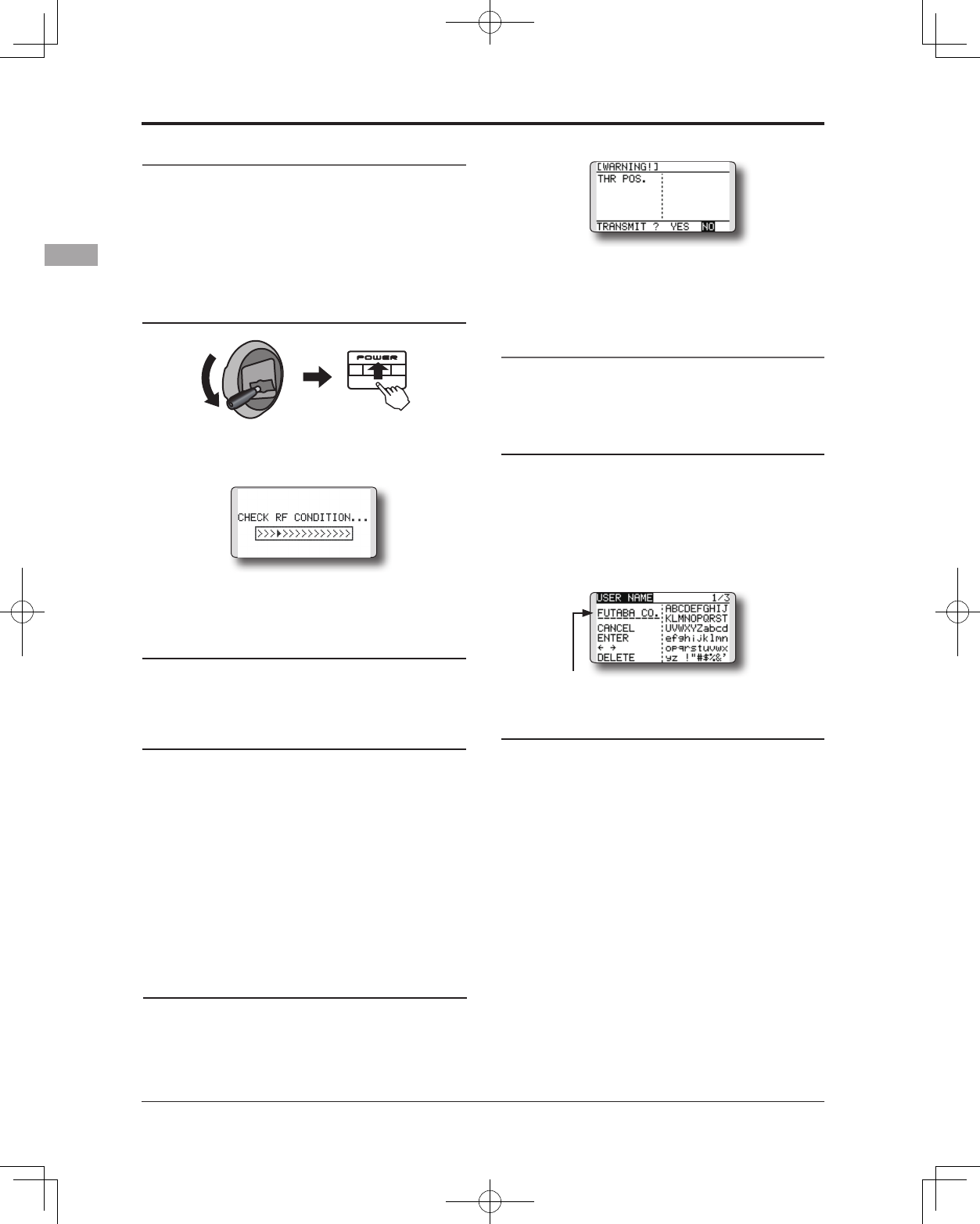
How to turn transmitter power ON/OFF
When turning on the power, the T14SG
transmitter will begin emmiting RF automatically
after it conrms the surrounding RF conditions.
The T14SG transmitter also offers the ability to
auto shut-down.
When turning on the power of the transmitter
1. Turn on the power switch of the transmitter.
*The message "CHECK RF CONDITION" is displayed for a
moment. At the same time the left LED monitor blinks.
2. Then, you will see the home screen and the
transmitter begins to emit radio waves.
*The left and right LED monitors will change to solid red.
How to stop the transmitter
1. Turn off the power switch of the transmitter.
*The transmitter shuts down at once.
Low battery alarm and auto shut-down
When the battery voltage reaches 5.2V, an
audible alarm will sound. Land your aircraft
immediately.
When the battery voltage reaches 3.9V, the
transmitter will be turned off automatically.
*If you do not operate the transmitter (or move a stick,
knob, switch or digital trim) for 30 minutes, the message
"PLEASE TURN OFF POWER SWITCH" is displayed and
an audible alarm will sound.
Warning display at power ON (Airplane/
Helicopter)
When the throttle stick during Power On is at
the high side (or over 1/3 stick) a warning will be
displayed.
*below 1/3 stick, the warning display goes off.
Registration of the user's name
If so desired, the T14SG transmitter can
indicate the owner's name.
User's name setup screen
1. Turn on the power of the transmitter.
*The home screen appears.
2. Lightly touch the SYS button twice rapidly
and the System menu appears.
3. Select [USER NAME] in the System menu and
touch the RTN button.
*The user name set up screen appears.
Input Box
*Current user name is displayed.
Changing the user name
1. Change the user name as described below:
[Moving cursor in input box]
Select[←]or[→],andtouchtheRTNbutton.
[Deleting a character]
When [DELETE] is selected and the RTN button
is touched, the character immediately after
the cursor is deleted.
[Adding a character]
When a character is selected from the
character list and the RTN button is touched,
that character is added at the position
immediately after the cursor.
*A name of up to 10 characters long can be entered as the
user name. (A space is also counted as one character.)
2. At the end of input, select [ENTER] and tuoch
the RTN button. (To terminate input and
return to the original state, select [CANCEL]
and touch the RTN button.)
THR Stick Slow
35
<Basic Operation>
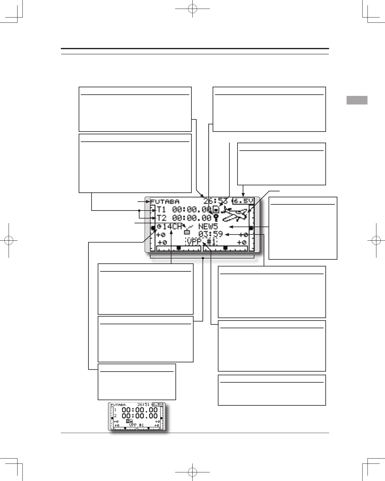
Up/Down timer (ST1, ST2)
•Timerisdisplayedhere.
Touch the RTN button at the [xx]:[xx.
xx] item to start/stop the timer.
• Usethecursortohighlightthis,then
touch the RTN button at the ST1 or ST2
item to call the timer set-up screen.
*See the description at the back of this manual.
Home screen
Digital trim (T1 to T4)
• Trimpositionisdisplayedhere.
• Youcanselectthedisplayunit
on the home screen on the
T1-T4 setting screen within the
linkage menu.
Model Name
•Themodelnamethat
is currently used is
displayed here.
•Usethecursorto
highlight this, then
touch the RTN button
to call the model
select set-up screen.
User's name
System timer
•Thisshowstheaccumulatedtimesince
the latest reset. (Hour):(Minute)
•Usethecursortohighlightthis,then
touch the RTN button for one second
to reset the system timer.
Use the touch sensor to select the following display area to call each setting screen, and touch the RTN
button. The setting screen appears.
RF indicator
Battery Indicator
• Whenthebatteryvoltage
reaches 5.2V(Change in
Warning Menu), the alarm
will beep. Land your aircraft
immediately.
System mode
•System(FASSTest14CHetc.)
mode is displayed here.
•Usethecursortohighlightthis,
then touch the RTN button
to call the frequency set-up
screen.
2nd Home screen
•TouchtheRTNbuttonat
the clock icon to call the
2nd home screen (large
size timer).
Model timer
•Thisshowstheaccumulated time
since the latest reset. (each model)
(Hour):(Minute)
•Usethecursortohighlightthis,
then touch the RTN button for one
second to reset the model timer.
Key lock
• TouchtheS1 buttonorpush the
HOME/EXIT button for one second to
lock/unlock the key operation.
In the key lock mode the key icon is
displayed here.
Model type
SD card indicator
Condition name (Heli/Glider)
•Inthenormalcondition,movethe
cursor to the condition name and
touch the RTN button. The condition
name is changed and blinks.
It is possible to operate the digital
trim in all conditions.
VPP condition # (Air)
•WhenVPPfunctionisassignedtoa
channel,thecurrentVPPcondition
# is displayed here.
36 <Basic Operation>
Warning
Be sure to conrm the model name before
ying your aircraft.
Check the battery voltage as often as
possible and try to charge the battery
earlier. If the battery alarm makes a sound,
land your aircraft immediately.
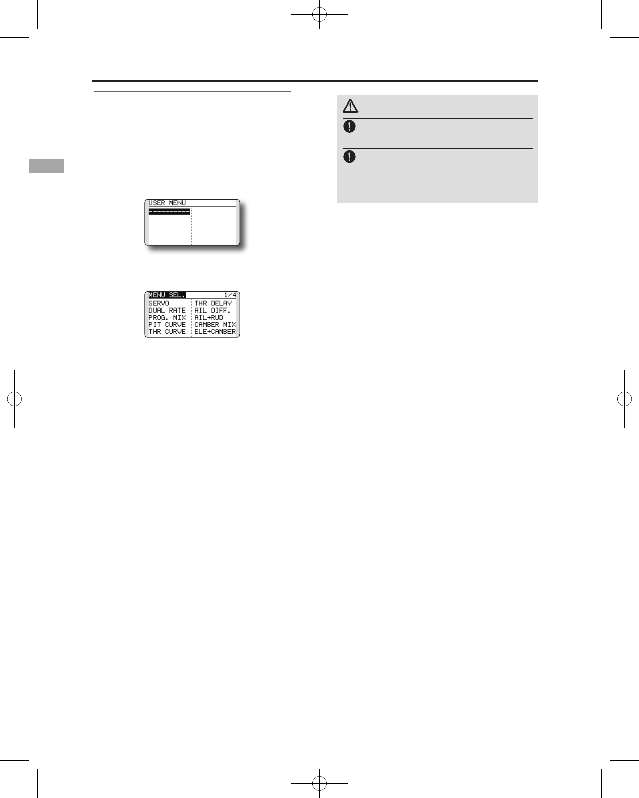
User Menu
A user menu which allows the user to
customize and display frequently used functions
has been added.
1. When the "U.MENU" button is pushed for
two seconds, the user menu appears.
* Return to the home screen by touching the EXIT button
while the user menu is being displayed.
2. When the cursor highlights the dotted line,
"----------" and the RTN button is touched,
the menu selection screen appears.
3. When the cursor is moved to the setting
that you to set to the user menu and the
RTN button is touched, that setting screen
is added to the user menu.
4. The registered setting screen can be
called by moving the cursor to it and
touching the RTN button.
*When you want to delete an added screen from the user
menu, highlight item you wish to delete, press and hold
the RTN button for one second.
37
<Basic Operation>
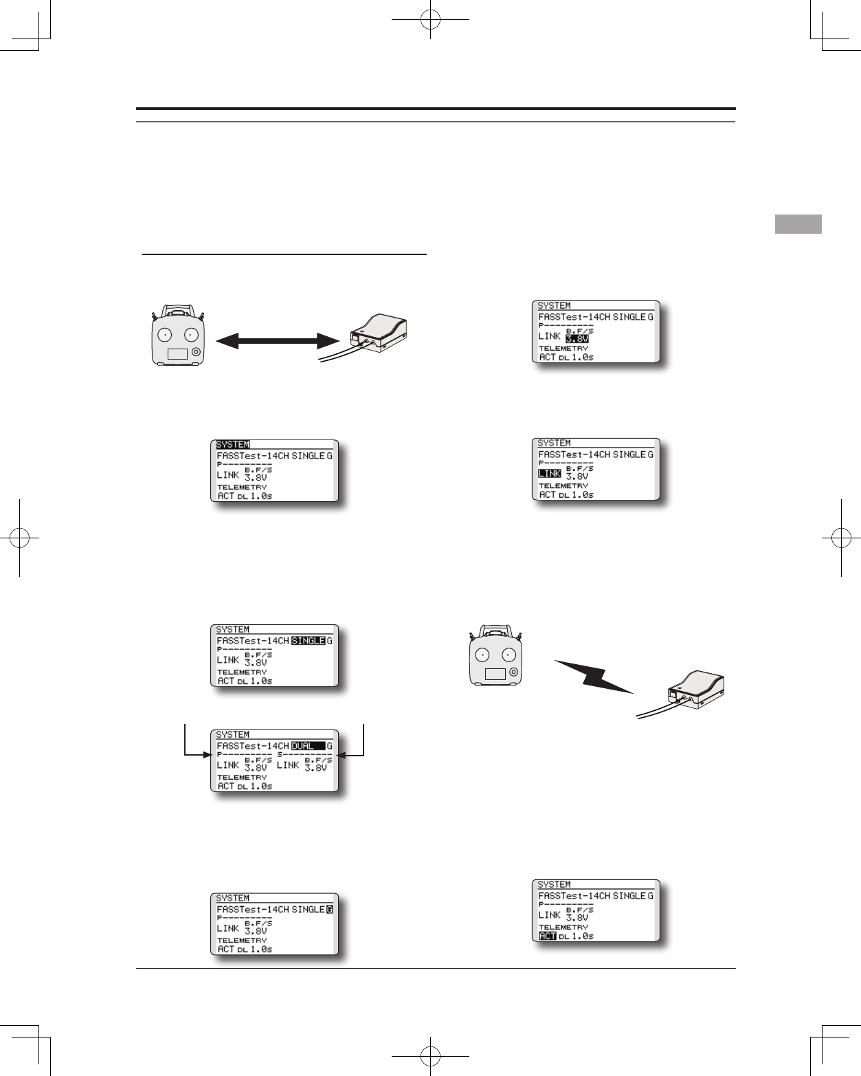
Link procedure (T14SG/R7008SB)
Each transmitter has an individually assigned, unique ID code. In order to start operation, the receiver
must be linked with the ID code of the transmitter with which it is being paired. Once the link is made,
the ID code is stored in the receiver and no further linking is necessary unless the receiver is to be used
with another transmitter. When you purchase additional R7008SB receivers, this procedure is necessary;
otherwise the receiver will not work.
Link procedure
1.Placethetransmitterandthereceiverclose
to each other within half (0.5m) meter.
2. Turn on the transmitter.
3. Select [SYSTEM] at the Linkage menu and
access the setup screen shown below by
touching the RTN button.
4. When you use two receivers on one model,
you must change from [SINGLE] to [DUAL].
*Only two receivers can be used. In
"DUAL", two setting items come out. Input,
respectively.
5."F"willbechosenifitisusedinFrance.others
"G" general.
6. When changing battery fail-safe voltage
from the initial value 3.8V, voltage is
changed here.
*OnlyinFASSTestMode.
7.[LINK] is chosen by scrolling and the RTN
button is pushed. The transmitter will emit a
chime as it starts the linking process.
8. When the transmitter starts to chime, power
on the receiver. The receiver should link to
the transmitter within about 1 second.
9. If linking fails, an error message is displayed.
Bring the transmitter closer to the receiver
and repeat the procedure above from Step 2.
10. ACT will be chosen if telemetry is used.
It is INH when not using it.
Less than 0.5 m
In "Link" Mode
Receiver ON
:You can do this through the LINKAGE Menu
and scroll to System and press RTN.
IDofaPrimary
receiver displays.
In DUAL, a primary receiver
is link previously. Next, a
secondary receiver is link.
ID of a Secondary
receiver displays.
38 <Basic Operation>
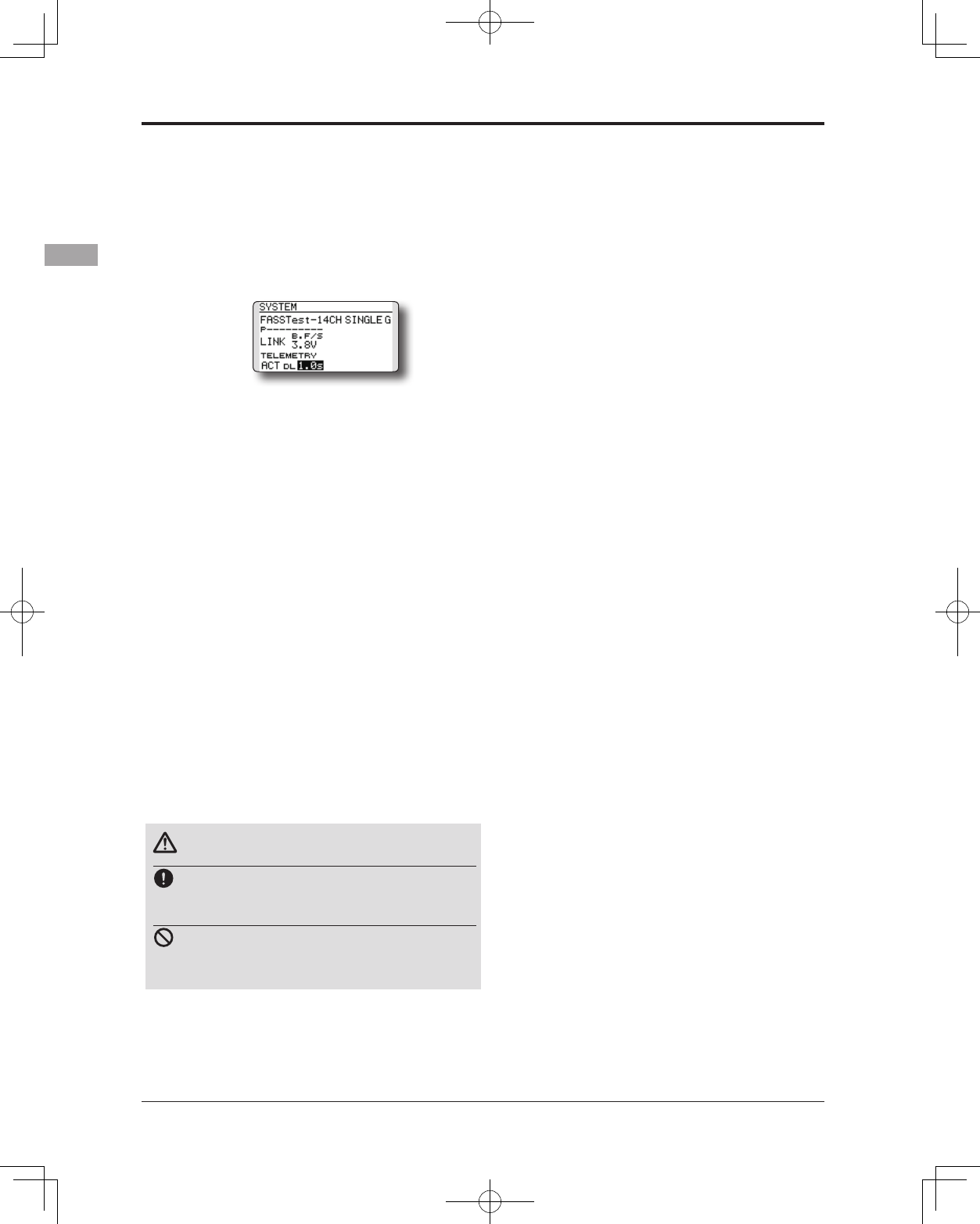
11. When a telemetry function is enabled,
the receiving interval (down-link interval) of
sensor data can be changed. If a DL interval
is increased, the response of the sensor data
display becomes slower, but stick response
will improve.
Initial value: 1.0s
Adjustment range: 0.1s~2.0s
* If there are many FASSTest systems turned on around your
receiver, it might not link to your transmitter. In this case,
even if the receiver's LED stays solid green, unfortunately
the receiver might have established a link to one of other
transmitters. This is very dangerous if you do not notice
this situation. In order to avoid the problem, we strongly
recommend you to doublecheck whether your receiver is
really under control by your transmitter by giving the stick
input and then checking the servo response.
*Do not perform the linking operation when the drive motor
is connected or the engine is running.
* When you use two receivers, please be sure to setup a
"primary" and "secondary" in the "dual" mode.
*Since two sets of receivers cannot be individually
recognized without using a "primary" and "secondary"
setup, it is impossible to receive telemetry data correctly.
* You must link one receiver at a time. If both power
supplies to the receivers are switched on simultaneously,
data is received incorrectly by the transmitter.
* If a dual receiver function is used, in order to receive
sensor information correctly by both sets, telemetry data
will be slower compared to a single receiver setup.
* You cannot link three receivers.
* Link is required when a system type is changed.
* Linking is required whenever a new model is made.
* Link is required when a system type is changed.
Warning
After the linking is done, please cycle receiver
power and check that the receiver to be linked
is really under the control of the transmitter.
Do not perform the linking procedure with
motor's main wire connected or with the engine
operating as it may result in serious injury.
39
<Basic Operation>
Range Testing Your R/C System
It is extremely important to range check your models prior to each flying session. This enables you to
ensure that everything is functioning as it should and to obtain maximum enjoyment from your time ying.
The T14SG transmitter incorporates a system that reduces its power output and allows you to perform such
a range check.
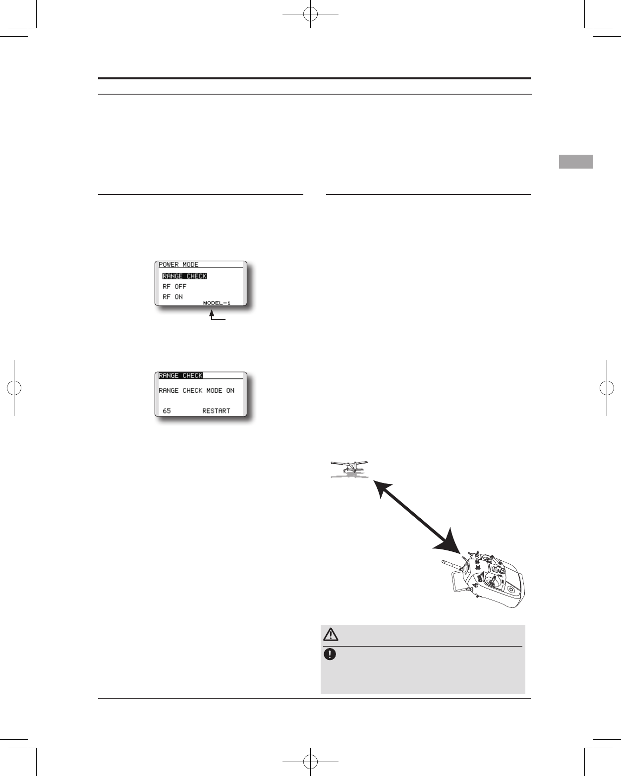
Range check mode
We have installed a special "Range check
mode" for doing a ground range check. To access
the "Range check mode" touch and hold the RTN
button while turning on the transmitter. Doing so
will bring up POWER MODE menu.
To activate the "Range check mode" touch the
RTN button and the range check mode screen will
appear.
During this mode, the RF power output is
reduced so the range test can be performed. In
addition, when this mode is activated the right
LED on the front of the transmitter starts blinking
and the transmitter gives users a warning with a
beeping sound every 3 seconds.
The "Range check mode" continues for 90
seconds and after that the power will return
to the normal level. To exit the "Range check
mode" before the 90 seconds, select the "RANGE
CHECK" at the top of the screen and touch the
RTN button again. This mode is available one
time only so if you need to re-use this function the
transmitter power must be cycled. NEVER start
ying when the "Range check mode" is active.
Should you require additional time to perform
a range check, highlight Restart before your time
expires and press the RTN button one time.
Range check procedure
1. With the "Range check mode" on, walk
away from the model while simultaneously
operating the controls. Have an assistant
stand by the model to confirm that all
controls are completely and correctly
operational. You should be able to walk
approximately 30-50 paces from the model
without losing control.
2. If everything operates correctly, return to
the model. Set the transmitter in a safe, yet
accessible, location so it will be within reach
after starting the engine or motor. Be certain
the throttle stick is in the low throttle position,
thenstarttheengineormotor.Perform
another range check with your assistant
holding the aircraft with the engine running
at various speeds. If the servos jitter or move
inadvertently, there may be a problem. We
wouldstronglysuggestyoudonotyuntilthe
sourceofthedifcultyhasbeendetermined.
Look for loose servo connections or binding
pushrods. Also, be certain that the battery
has been fully charged.
The present model
About 100 feet
Range check mode
Range checking on
low power.
Warning
Do not y in the range check mode.
*Since the range of the radio waves is short, if the model
is too far from the transmitter, control will be lost and the
model will crash.
40 <Receiver and Servo Installation>
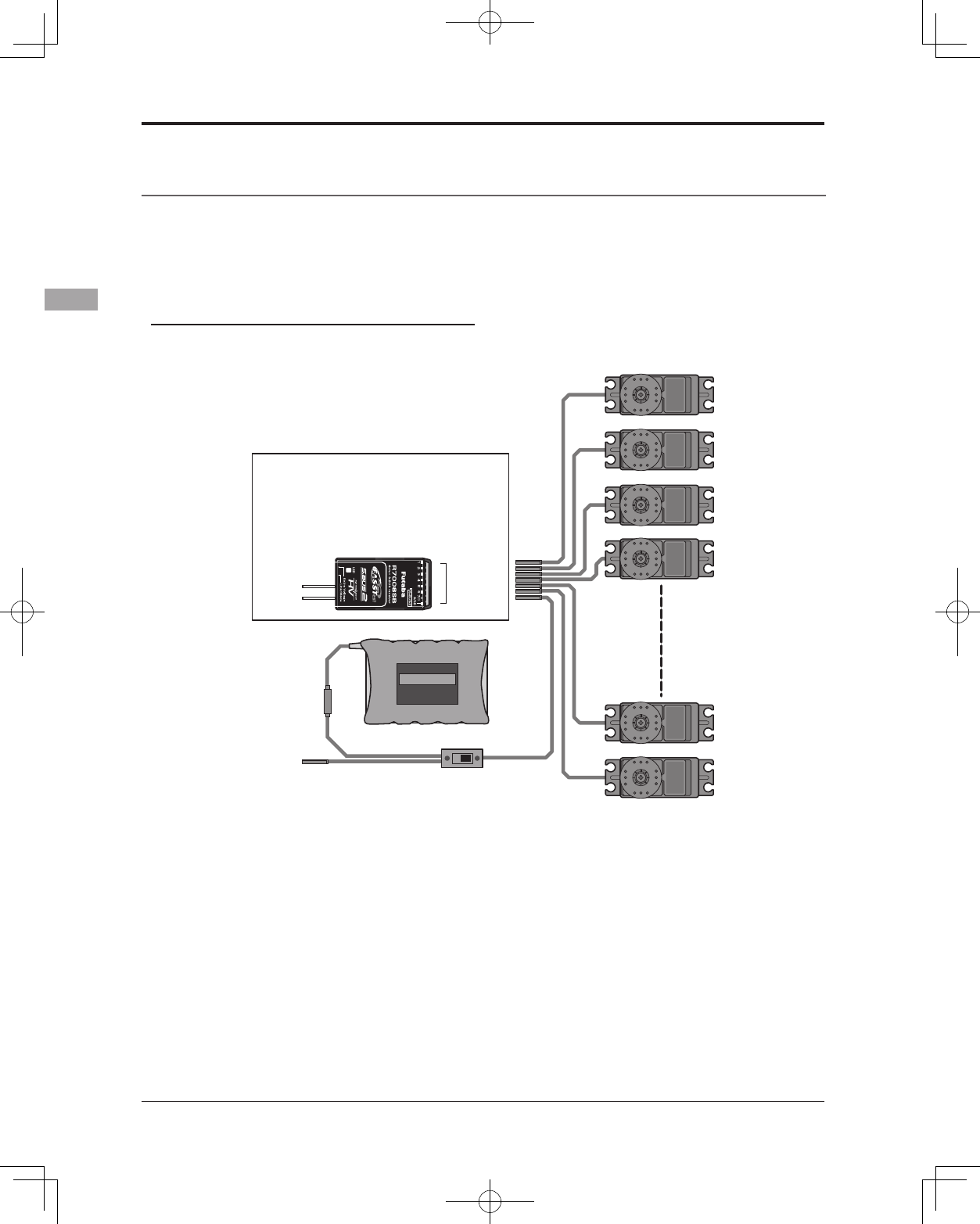
RECEIVER AND SERVO INSTALLATION
Receiver switch
Receiver battery
Charging port
Servos
R7008SB (output connector section)
•CH1~6: Output connectors 1~6
•7/B: Output connectors 7 and Power supply
•8/SB: Output connectors 8 or S.BUS system
•S.BUS2: S.BUS2 system
CH1~8,
S.BUS/(2),
B
Receiver and servos connection diagram
Always connect the necessary number of servos.
The receiver channel assignment depends on the
model type. See the Servo connection by model
type tables.
Receiver and servos connection
Connect the receiver and servos in accordance with the connection diagram shown below. Always read the
section [Before using]. When mounting the receiver and servos to the fuselage, connect the necessary points
in accordance with the model's instruction manual.
41
<Receiver and Servo Installation>
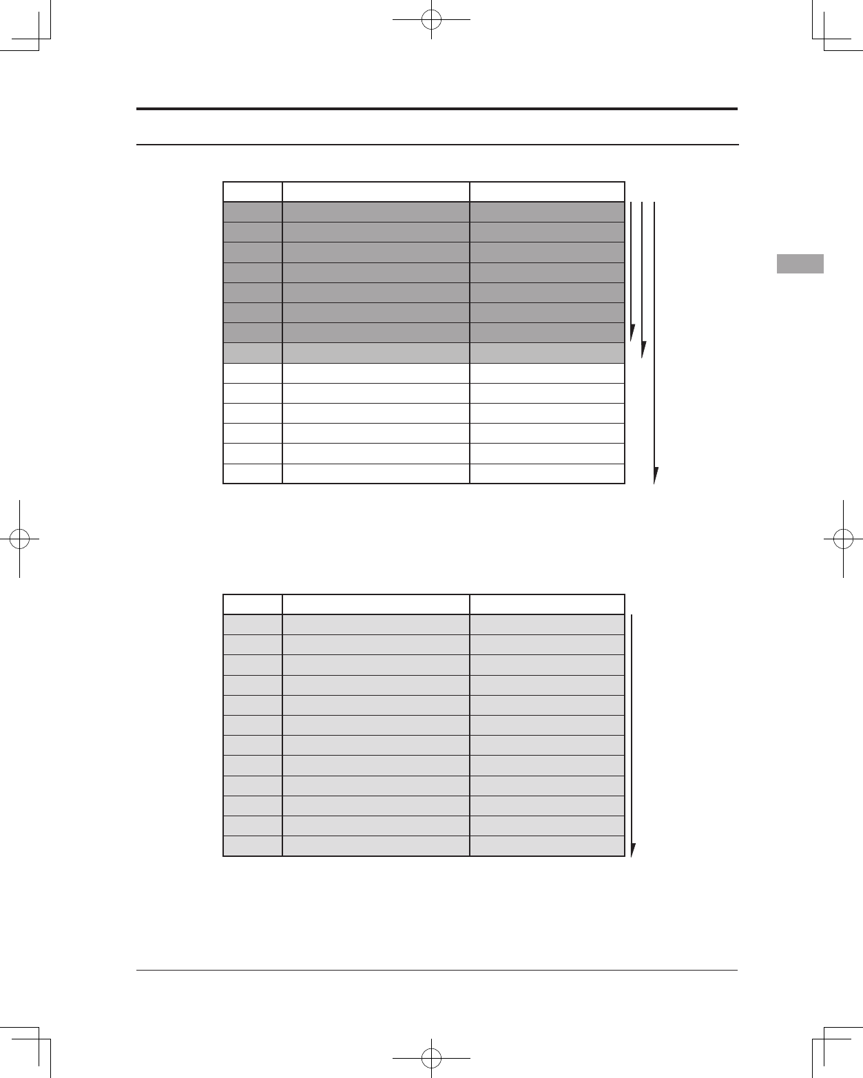
Servo connection by model type
The T14SG transmitter channels are automatically assigned for optimal combination according to the type
selected with the Model Type function of the Linkage Menu. The channel assignment (initial setting) for
each model type is shown below. Connect the receiver and servos to match the type used.
*The set channels can be checked at the Function screen of the Linkage Menu. The channel assignments can also be changed. For
more information, read the description of the Function menu.
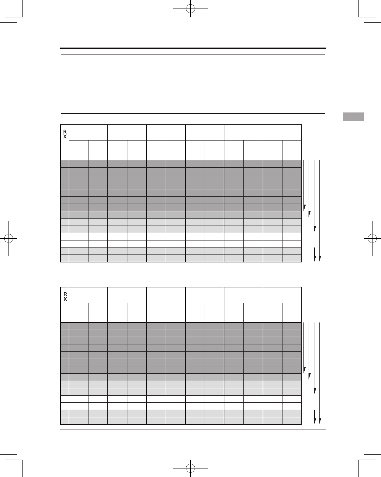
Airplane/glider
Normal wing and V-tail
1Aileron 2Aileron 2Aileron+1FLAP 2Aileron+2FLAP 2Aileron+4FLAP 4Aileron+2FLAP
Airplane Glider Airplane Glider Airplane Glider Airplane Glider Airplane Glider Airplane Glider
1 Aileron Aileron Aileron Aileron Aileron Aileron Aileron Aileron Aileron Aileron Aileron Aileron
2
Elevator Elevator Elevator Elevator Elevator Elevator Elevator Elevator Elevator Elevator Elevator Elevator
3 Throttle Motor Throttle Motor Throttle Motor Throttle Motor Rudder Rudder Rudder Rudder
4 Rudder Rudder Rudder Rudder Rudder Rudder Rudder Rudder Aileron2 Aileron2 Aileron2 Aileron2
5 Gear AUX7 Gear AUX7 Gear AUX6 Gear AUX5 Flap Flap Aileron3 Aileron3
6 VPP AUX6 Aileron2 Aileron2 Flap Flap Aileron2 Aileron2 Flap2 Flap2 Aileron4 Aileron4
7 AUX5 AUX5 VPP AUX6 Aileron2 Aileron2 Flap Flap Flap3 Flap3 Flap Flap
8 AUX4 AUX4 AUX5 AUX5 VPP AUX5 Flap2 Flap2 Flap4 Flap4 Flap2 Flap2
9 AUX1 AUX1 Camber Camber Camber Camber Camber Camber Camber Camber Camber Camber
10 AUX1 AUX1 AUX1 Buttery AUX1 Buttery VPP Buttery Gear Buttery Gear Buttery
11 AUX1 AUX1 AUX1 AUX1 AUX1 AUX1 AUX1 AUX1 Throttle Motor Throttle Motor
12 AUX1 AUX1 AUX1 AUX1 AUX1 AUX1 AUX1 AUX1 VPP AUX1 VPP AUX1
DG1 SW SW SW SW SW SW SW SW SW SW SW SW
DG2 SW SW SW SW SW SW SW SW SW SW SW SW
1Aileron 2Aileron 2Aileron+1FLAP 2Aileron+2FLAP 2Aileron+4FLAP 4Aileron+2FLAP
Airplane Glider Airplane Glider Airplane Glider Airplane Glider Airplane Glider Airplane Glider
1 Aileron Aileron Aileron Aileron Aileron Aileron Aileron Aileron Aileron Aileron Aileron Aileron
2
Elevator Elevator Elevator Elevator Elevator Elevator Elevator Elevator Elevator Elevator Elevator Elevator
3 Throttle Motor Throttle Motor Throttle Motor Throttle Motor Rudder Rudder Rudder Rudder
4 Rudder Rudder Rudder Rudder Rudder Rudder Rudder Rudder Aileron2 Aileron2 Aileron2 Aileron2
5 Gear AUX7 Gear AUX7 Gear AUX6
Elevator2 Elevator2
Flap Flap Aileron3 Aileron3
6 VPP AUX6 Aileron2 Aileron2 Flap Flap Aileron2 Aileron2 Flap2 Flap2 Aileron4 Aileron4
7
Elevator2 Elevator2 Elevator2 Elevator2
Aileron2 Aileron2 Flap Flap Flap3 Flap3 Flap Flap
8 AUX4 AUX4 VPP AUX5
Elevator2 Elevator2
Flap2 Flap2 Flap4 Flap4 Flap2 Flap2
9 AUX1 AUX1 Camber Camber Camber Camber Camber Camber Camber Camber Camber Camber
10 AUX1 AUX1 AUX1 Buttery VPP Buttery Gear Buttery Gear Buttery Gear Buttery
11 AUX1 AUX1 AUX1 AUX1 AUX1 AUX1 VPP AUX1 Throttle Motor Throttle Motor
12 AUX1 AUX1 AUX1 AUX1 AUX1 AUX1 AUX1 AUX1
Elevator2 Elevator2 Elevator2 Elevator2
DG1 SW SW SW SW SW SW SW SW SW SW SW SW
DG2 SW SW SW SW SW SW SW SW SW SW SW SW
CH
CH
FASST 7CH
S-FHSS
FASSTest 12CH
FASSTest 14CH FASST MULT
FASST 7CH
S-FHSS
FASSTest 12CH
FASSTest 14CH FASST MULT
Ailvator (Dual Elevator)
The output
CH of each
system
The output
CH of each
system
42 <Receiver and Servo Installation>
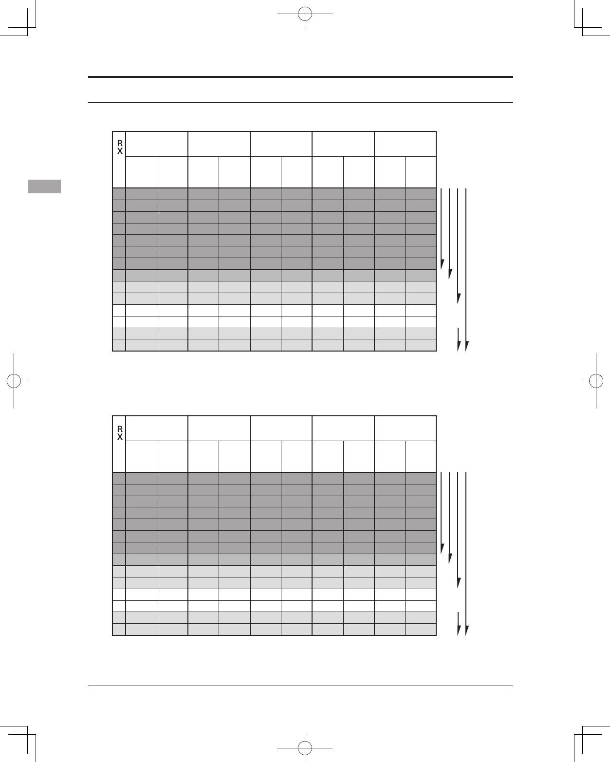
Flying wing, Delta wing (Winglet 2 Rudder)
Flying wing, Delta wing
2Aileron 2Aileron+1FLAP 2Aileron+2FLAP 2Aileron+4FLAP 4Aileron+2FLAP
Airplane Glider Airplane Glider Airplane Glider Airplane Glider Airplane Glider
1 Aileron Aileron Aileron Aileron Aileron Aileron Aileron Aileron Aileron Aileron
2 VPP AUX4 VPP AUX4 VPP AUX4 Aileron2 Aileron2 Aileron2 Aileron2
3 Throttle Motor Throttle Motor Throttle Motor Rudder Rudder Aileron3 Aileron3
4 Rudder Rudder Rudder Rudder Rudder Rudder VPP AUX4 Aileron4 Aileron4
5 Gear AUX7 Gear AUX6 Gear AUX6 Flap Flap Rudder Rudder
6 Aileron2 Aileron2 Flap Flap Flap Flap Flap2 Flap2 VPP AUX4
7 AUX6 AUX6 Aileron2 Aileron2 Aileron2 Aileron2 Flap3 Flap3 Flap Flap
8 AUX5 AUX5 AUX5 AUX5 Flap2 Flap2 Flap4 Flap4 Flap2 Flap2
9
Elevator Elevator Elevator Elevator Elevator Elevator Elevator Elevator Elevator Elevator
10 Camber Camber Camber Camber Camber Camber Camber Camber Camber Camber
11 AUX1 AUX1 AUX1 Buttery AUX1 Buttery Gear Buttery Gear Buttery
12 AUX1 AUX1 AUX1 AUX1 AUX1 AUX1 Throttle Motor Throttle Motor
DG1 SW SW SW SW SW SW SW SW SW SW
DG2 SW SW SW SW SW SW SW SW SW SW
CH
FASST 7CH
S-FHSS
FASSTest 12CH
FASSTest 14CH FASST MULT
2Aileron 2Aileron+1FLAP 2Aileron+2FLAP 2Aileron+4FLAP 4Aileron+2FLAP
Airplane Glider Airplane Glider Airplane Glider Airplane Glider Airplane Glider
1 Aileron Aileron Aileron Aileron Aileron Aileron Aileron Aileron Aileron Aileron
2 Rudder2 Rudder2 Rudder2 Rudder2 Rudder2 Rudder2 Aileron2 Aileron2 Aileron2 Aileron2
3 Throttle Motor Throttle Motor Throttle Motor Rudder Rudder Aileron3 Aileron3
4 Rudder Rudder Rudder Rudder Rudder Rudder Rudder2 Rudder2 Aileron4 Aileron4
5 Gear AUX7 Gear AUX6 Gear AUX6 Flap Flap Rudder Rudder
6 Aileron2 Aileron2 Flap Flap Flap Flap Flap2 Flap2 Rudder2 Rudder2
7 VPP AUX6 Aileron2 Aileron2 Aileron2 Aileron2 Flap3 Flap3 Flap Flap
8 AUX5 AUX5 VPP AUX5 Flap2 Flap2 Flap4 Flap4 Flap2 Flap2
9
Elevator Elevator Elevator Elevator Elevator Elevator Elevator Elevator Elevator Elevator
10 Camber Camber Camber Camber Camber Camber Camber Camber Camber Camber
11 AUX1 AUX1 AUX1 Buttery VPP Buttery Gear Buttery Gear Buttery
12 AUX1 AUX1 AUX1 AUX1 AUX1 AUX1 Throttle Motor Throttle Motor
DG1 SW SW SW SW SW SW SW SW SW SW
DG2 SW SW SW SW SW SW SW SW SW SW
CH
FASST 7CH
S-FHSS
FASSTest 12CH
FASSTest 14CH FASST MULT
* Output channels differ by each system of a table. When using a system with few channels, there
is a wing type which cannot be used. It cannot be used when there is a function required out of
the range of the arrow of a gure.
The output
CH of each
system
The output
CH of each
system
Airplane/glider
43
<Receiver and Servo Installation>
● FASSTest12CH
● FASSTest14CH/FASST MULTI/FASST 7CH/S-FHSS
CH All Other H-4, H4X Swash
1 Aileron Aileron
2 Elevator Elevator
3 Throttle Throttle
4 Rudder Rudder
5 Gyro/RUD Gyro/RUD
6 Pitch Pitch
7 Governor Governor
8 Needle Elevator2
9 Gyro2/AIL Gyro2/AIL
10 Gyro3/ELE Gyro3/ELE
11 AUX1 AUX1
12 AUX1 AUX1
DG1 SW SW
DG2 SW SW
FASST 7CH
S-FHSS
FASSTest 14CH FASST MULT
CH All Other H-4, H4X Swash
1 Aileron Aileron
2 Elevator Elevator
3 Throttle Throttle
4 Rudder Elevator2
5 Pitch Pitch
6 Gyro/RUD Gyro/RUD
7 Governor Governor
8 Governor 2 Rudder
9 Gyro2/AIL Gyro2/AIL
10 Gyro3/ELE Gyro3/ELE
DG1 SW SW
DG2 SW SW
FASSTest 12CH
Helicopter
● Since the ch8 doesn't work on the 7-ch mode, please assign the
elevator2 (H-4, H4X) or the needle (all other) to 7 channnel if the
governor is not used.
The output
CH of each
system
The output
CH of each
system
44 <Model Basic Setting Procedure>
MODEL BASIC SETTING PROCEDURE
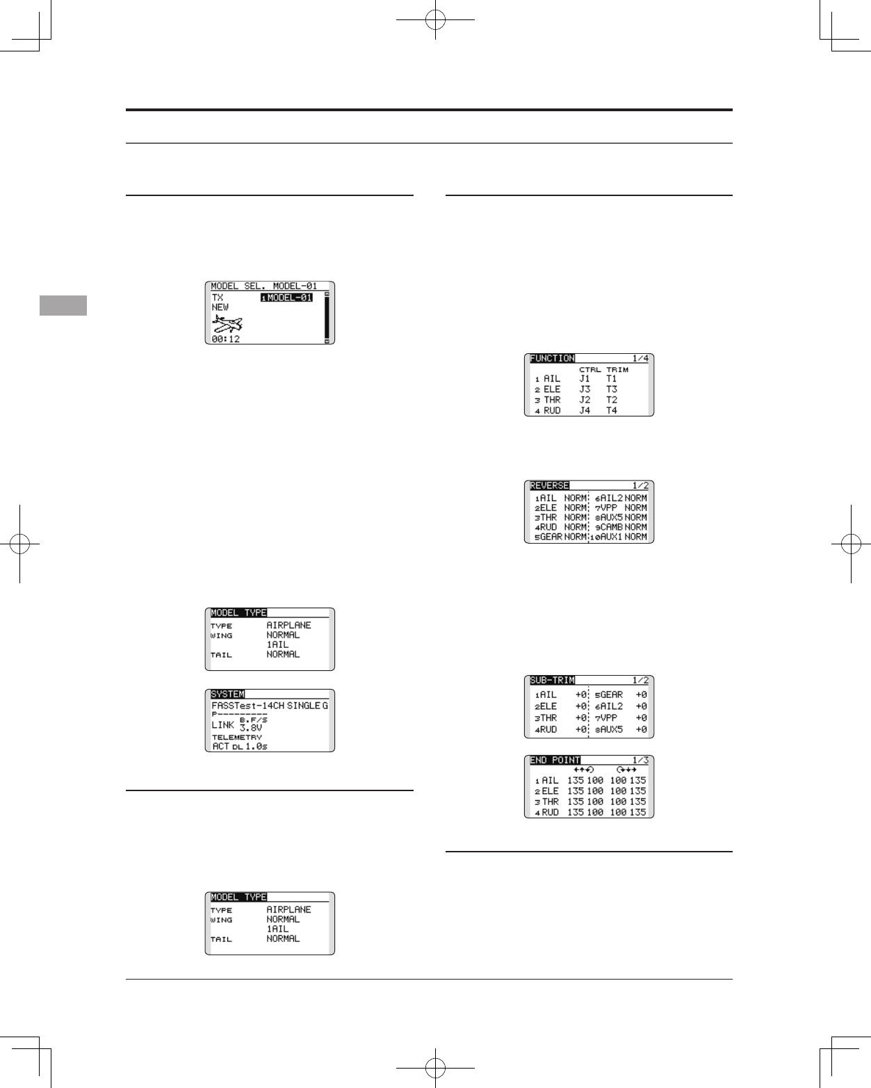
1. Model addition and selection
Initially, the T14SG assigns the first model to
model-01 in the transmitter. The Model Select
function of the Linkage Menu is used to add
models and to select amongst models which are
already set.
The T14SG is capable of storing data for up
to 30 models in its internal memory. Additional
model data can also be saved to an optional SD
card.
The currently selected model name is displayed
in the center of the home screen. Before ying and
before changing any settings, always confirm the
model name.
When a new model is added, the Model type
select screen and System mode setup screen
automatically appear. Please be aware that the
transmitter will stop transmitting temporarily when
you change the model.
When a new model is added, you will need to re-
link the receiver.
2. Model type selection
Select the model type matched to the aircraft
with the Model Type select function of the Linkage
Menu. For an airplane, select the model type from
among the 2 types: airplane and glider. And then
select the wing type and the tail type matched to
the aircraft.
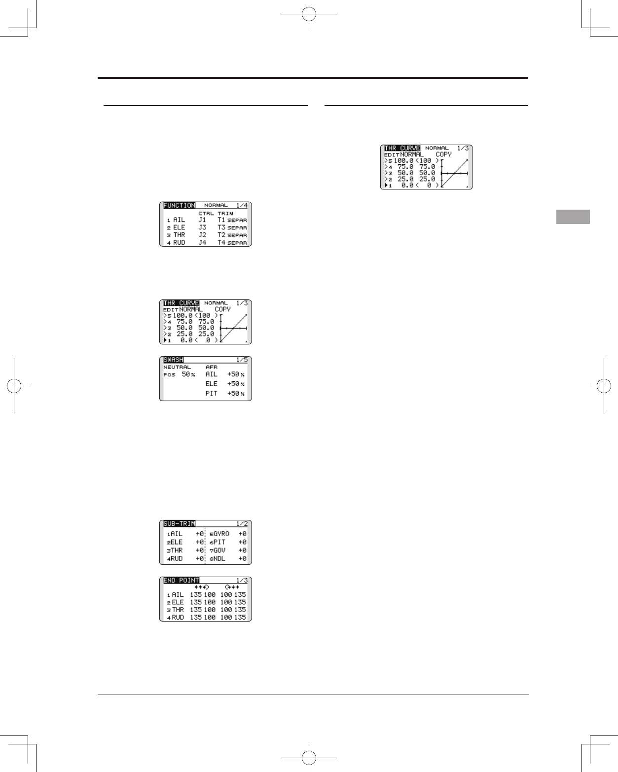
Airplane/glider basic setting procedure
3. Fuselage linkage
Connect the ailerons, elevators, throttle, rudder,
etc. in accordance with the model's instruction
manual. For a description of the connection
method, see the Receiver and Servos Connection.
Note that even for the same "airplane
model", when the wing type and tail type
are different, the channel assignment may
be different. (The channel assigned to each
function can be checked at the Function
menu of the Linkage Menu.)
● Ifthedirectionoftheservoisincorrect,adjust
thedirectionwiththeReversefunctionofthe
LinkageMenu.
● Adjusttheneutralpositionandcontrol
surfaceanglewiththelinkage,andfine
tunethemwiththeSub-TrimandEndPoint
functions(angleadjustment).Toprotectthe
linkage,alimitpositioncanalsobesetwith
theEndPointfunction.TheEndPointfunction
canadjusttheamountofup/downandleft/
rightmovementandlimitofeachchannel.
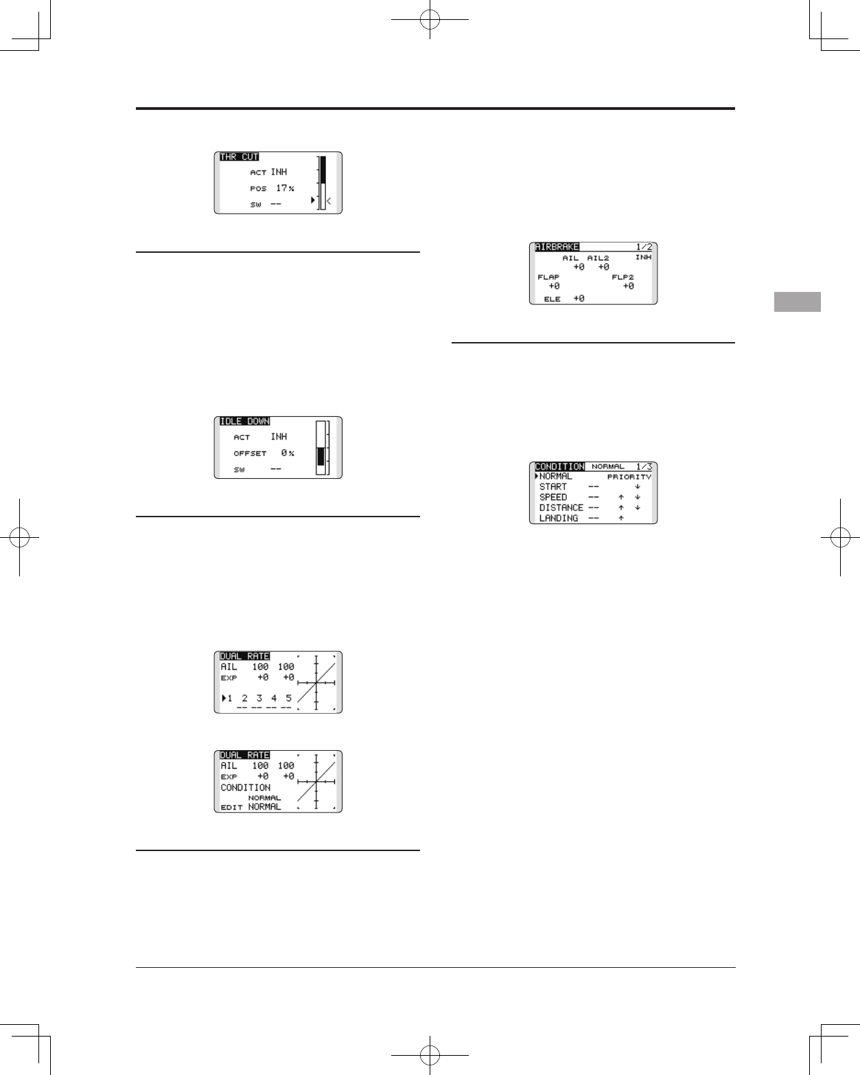
4. Throttle cut setting (Airplane)
Throttle cut can be performed with one touch by a
switch without changing the throttle trim position.
Set throttle cut with the Throttle Cut function of
the Linkage Menu. After activating the throttle cut
function and selecting the switch, adjust the throttle
position so that the carburetor becomes fully closed.
For safety, the throttle cut function operates the
45
<Model Basic Setting Procedure>
throttle stick in the 1/3 or less (slow side) position.
5. Idle down setting (Airplane)
The idling speed can be lowered with one touch
by a switch without changing the throttle trim
position. Perform this setting with the Idle Down
function of the Linkage Menu. After activating the
Idle Down function and selecting the switch, adjust
the idle down speed. For safety, the idle down
function acts only when the throttle stick is in the
lowest part of its throw.
*While the Throttle Cut function is in operation, the Idle
Down function does not work.
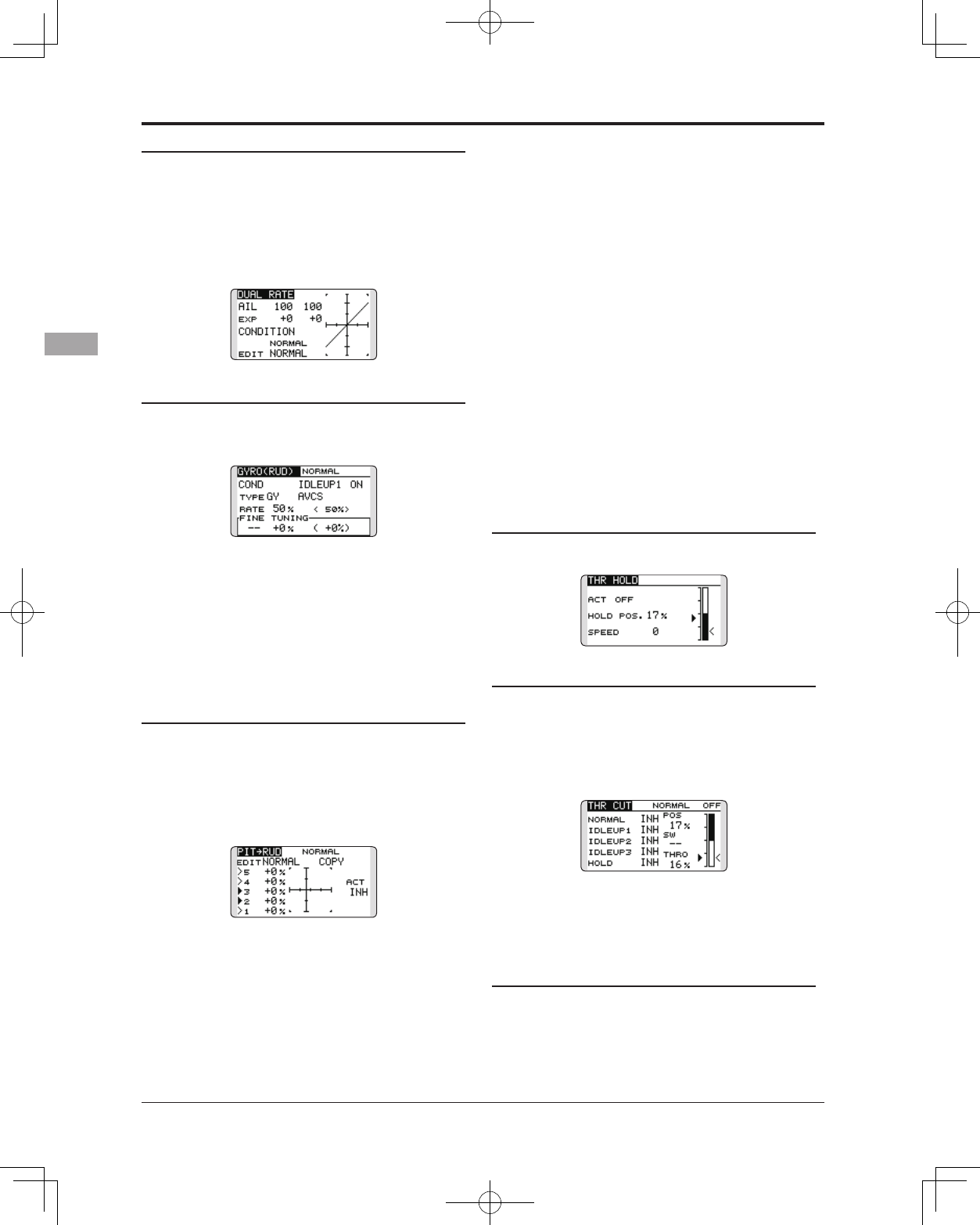
6. D/R function
D/R function is used to adjust the throw and
operation curve of the stick functions (aileron,
elevator, rudder and throttle) for each switch
position (airplane) or each ight condition (glider).
This is normally used after the modeler has dened
the maximum throw directions in the End Point
settings.
(Airplane)
(Glider)
7. Airbrake (Airplane)
This function is used when an airbrake is
necessary when taking off or diving, etc. Please
note: this menu item is only available under certain
wing congurations. For example, it will not appear
if a single aileron wing type has been selected.
The pre-set elevator and ap offset amount can
be activated by a switch.
The offset amount of the aileron, elevator, and
flap servos can be adjusted as needed. Also the
speed of the aileron, elevator, and ap servos can
be adjusted. You can also set the Auto Mode, which
will link Airbrake to a stick, switch, or dial. A
separate stick switch or dial can also be set as the
ON/OFF switch.
8. Addition of ight conditions (Glider)
The Condition Select function automatically
allocates the normal condition (NORMAL) for
each model. NORMAL is the default condition and
is the only one active when a new model type is
dened.
If you want to add ight conditions, please refer
to a description of the CONDITION function.
*The NORMAL is always on, and remains on until other
conditions are activated by switches, stick positions, etc.
Please refer to the section entitled Switch Selection Method
for additional information on how to do so.
*It is possible to customize the activation of the flight
conditions.
*The Condition Delay can be programmed for each channel.
The Condition Delay is used to change the servo throw
smoothly when switching conditions.
46 <Model Basic Setting Procedure>
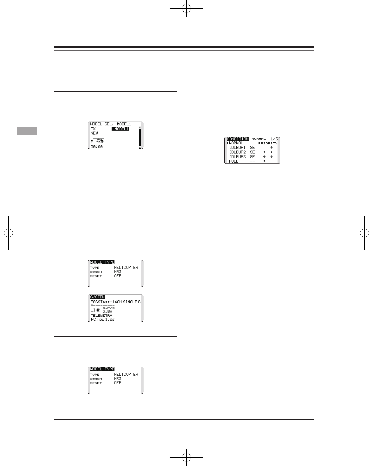
1. Model addition and selection
Initially, the T14SG assigns the first model to
model-01 in the transmitter. To add new models
or to select a model already programmed, use the
Model Select function of the Linkage Menu.
This is convenient when selecting a model
after entering the model's names in advance. The
T14SG is capable of storing up to 30 models in the
transmitter's internal memory. Additional models
can also be stored in an optional SD card.
The currently selected model is displayed in
the middle of the screen. Before flying and before
changing any settings, always confirm the model
name.
When a new model is added, the Model Type select
screen and system mode setup screen automatically
appear. Change, or check that they match the swash
type and receiver type of the model used.
When a new model is added, you will need to re-
link the receiver.
2. Model type and swash type selection
If a different model type is already selected,
select helicopter with the Model Type function of
the Linkage Menu, and then select the swash type
matched to the helicopter.
*The Model Type function automatically selects the
appropriate output channels, control functions, and mixing
Helicopter basic setting procedure
This section outlines examples of use of the helicopter functions of the T14SG. Adjust the actual values,
etc. to match the fuselage used.
functions for the chosen model type. Six swash types are
available for helicopters.
*For a description of the swash type selection, refer to the
MODEL TYPE function.
3. Flight condition addition
The transmitter offers up to ve ight conditions
per model.
The Condition Select function automatically
allocates ve conditions for helicopters.
(Initialsetting)
●NORMAL
●IDLEUP1(SW-E)
●IDLEUP2(SW-E)
●IDLEUP3(SW-F)
●HOLD(Holdswitchisnotassignedinitially)
Note: Since you may accidentally activate
a condition that not previously setup during
ight which could cause a crash, we suggest
deleting conditions that are not used.
*For a description of the condition deletion, refer to the
Condition Select function.
The NORMAL condition is always on, and
remains on until other conditions are activated by
switches.
The priority is throttle hold/idle up 3/idle up 2/
idle up 1/normal. Throttle hold has the highest
priority.
The Condition Delay can be programmed for
each channel and condition. The Condition Delay
is used to change the servo throw smoothly when
switching conditions.
(General ight condition setting example)
●Normal:(Useinitialsettingconditions/operate
whenswitchOFF)
Usefromenginestartingtohovering.
●Idleup1:(OperateatSW-Ecenter)
Useinstallturn,loop,andothermaneuvers.
●Idleup2:(OperateatSW-Eforwardside)
Useinrolls.
●Throttlehold:(OperateatSW-Gforwardside)
Useinautorotation.
47
<Model Basic Setting Procedure>
5. Throttle/Pitch curve setting
This function adjusts the throttle or pitch
operation curve in relation to the movement of the
throttle stick for each condition.
<Throttle curve setting example>
Activate the throttle curve of each condition with
the condition select switch.
●Normalcurveadjustment
Normalcurvecreates abasicthrottlecurve
centerednearhovering.Thiscurveis adjusted
togetherwiththe pitchcurve(Normal)sothatthe
enginespeedis constantandup/downcontrolis
easiest.
●Idleupcurveadjustment
ThelowsideThrottlecurvecreates acurve
matchedforaerobatics(loop,roll,3D,etc.).
●Throttleholdcurveadjustment
Conrmthattherateoftheslowestposition(0%)of
thestickis0%(initialsetting).
<Example of pitch curve setting>
Activate the pitch curve of each condition with
the condition select switch.
●Pitchcurve(Normal)
Makethepitchathoveringapproximately+5º~6º.
Setthepitchathoveringwiththestickpositionat
the50%pointasthestandard.
*Stability at hovering may be connected to the throttle curve.
Adjustment is easy by using the hovering throttle function
and hovering pitch function together.
●Pitchcurve(Idleup1)
Theidleup 1pitchcurvefunctioncreates acurve
matchedtoairborneight.
Setto-7º~+12ºasstandard.
●Pitchcurve(Idleup2)
Thehighsidepitchsettingislessthanidleup1.
Thestandardis+8º.
●Pitchcurve(Hold)
Atautorotation,usethemaximumpitchatboth
thehighandlowsides.
[Pitchanglesettingexample]
Throttlehold:-7º~+12º
4. Servo Connection
Connect the throttle rudder, aileron, elevator,
pitch, and other servos in accordance with the
kit instruction manual. For a description of the
connection method, see "Receiver and Servos
Connection".
Note: The channel assigned to each function
can be checked at the Function menu of the
Linkage Menu.
●Ifthedirectionofoperationoftheservo
isincorrect,usetheReversefunctionof
theLinkageMenu.AlsousetheswashAFR
functioninotherthantheH-1mode.
●Adjustthedirectionofoperationofthegyro.
(Gyrosidefunction)
●Connectthethrottlelinkagesothatthe
carburetorcanfullycloseatfulltrimthrottle
cut.
●Adjusttheneutralpositionatthelinkageside
andnetunewiththeSub-Trimfunctionand
EndPointfunction.Toprotectthelinkage,
alimitpositioncanalsobesetwiththeEnd
Pointfunction.
●Swashplatecorrection(ExceptH-1mode)
*If any interactions are noticed, for a description of the
linkage correction function, please refer to the SWASH
function.
48 <Model Basic Setting Procedure>
function from the Model Menu, and set the curve
for each condition. (At initial setting, this function
is in the "INH" state. To use it, set it to the "ON"
state.)
<Setting example>
Activate the mixing curve of each condition with
the condition select switch.
Acurvesettingexampleisshownbelow.
●PitchtoRUDmixingcurve(Normal)
Usethehovering systemandsetthiscurve to
matchtakeoffandlandingandverticalclimbata
constantspeed.
●PitchtoRUDmixing(Idleup1)
Usethiscurveinstallturn,loop,andadjustitsothe
fuselageisfacingstraightahead whenheading
intothewind.
●PitchtoRUDmixing(Hold)
Thisfunctionissetsothatthefuselageisfacing
straightaheadatstraightlineautorotation.The
pitchofthetailrotorbecomesnearly0º.
9. Throttle hold setting
*If throttle hold is necessary, please refer to the THR HOLD
function.
10. Throttle cut setting
Throttle cut provides an easy way to stop the
engine, by ipping a switch with the throttle stick
at idle. The action is not functional at high throttle
to avoid accidental dead sticks. The switch’s
location and direction must be chosen, as it defaults
to NULL.
*With throttle stick at idle, adjust the cut position until the
engine consistently shuts off, but throttle linkage is not
binding.
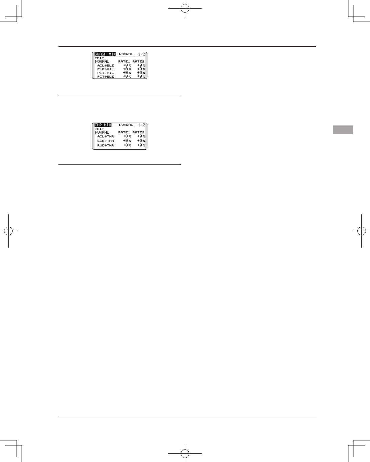
11. Swash Mix corrects aileron, elevator and
pitch interaction
The swash mix function is used to correct the
swash plate in the aileron (Left/Right Cyclic)
and elevator (Forward/Aft Cyclic) direction
corresponding to each operation of each condition.
6. D/R function
D/R function is used to adjust the throw and
operation curve of aileron, elevator and rudder for
each condition.
*For throttle and pitch curve settings, refer to the afore-
mentioned "Throttle/Pitch curve setting"
This is normally used after End Point has dened
the maximum throw directions.
7. Gyro sensitivity and mode switching
The gyro sensitivity and mode switching
function is utilized to adjust the gyro mixing of the
model, and can be set for each condition.
● Normalcondition(hovering):Gyrosensitivity
maximum
● Idleup1/Idle up2/Throttlehold:Gyro
sensitivityminimum
● However,duringautorotationswithatail-
drivenhelicopter,thisfunctionmaynothave
anyeffectonthehighgyrosensitivity.
8. Pitch to RUD mixing setting
Note: When using a Futaba GY Gyro, or other
heading hold gyro, this Pitch to RUD mixing
should not be used. The reaction torque is
corrected by the gyro. When operating the
gyro in the AVCS mode, the mixed signal will
cause neutral deviation symptoms and the
gyro will not operate normally.
Use this function when you want to suppress
the torque generated by the changes in the pitch
and speed of the main rotor during pitch operation.
Adjust it so that the nose does not swing in the
rudder direction. However, when using a heading
hold gyro like those shown above, do not use Pitch
to rudder mixing.
Activate the Pitch to rudder (Pit -->RUD) mixing
49
<Model Basic Setting Procedure>
12. Throttle mixing setting
*If throttle mixing is necessary for a compensation for
slowing of engine speed caused by swash plate operation
during aileron or elevator operation, please refer to the
THROTTLE MIX function.
13. Other special mixings
●PitchtoNeedlemixing
Thismixingisusedwithengineswithadesignwhich
allowsneedlecontrolduringflight(fuel-airmixture
adjustment).Aneedlecurvecanbeset.
●Governormixing
Thismixingis dedicatedgovernormixingwhena
governorisused.
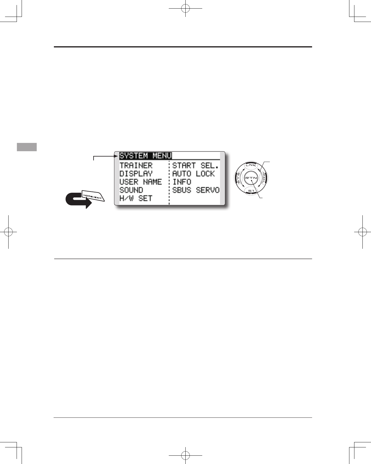
50 <Functions of System Menu>
SYSTEM MENU
System Menu functions table
[TRAINER]: Starts and sets the trainer system.
[DISPLAY]: LCD and back-light adjustment
[USER NAME]: User name registration
[SOUND]: Turns off the buzzer.
[H/W SET]: H/W reverse, calibration and stick mode
[START SEL.]: Immediately, a model selection can be performed
[AUTO LOCK]: The automatic lock function of two kinds of touch sensors
[INFO]: Displays the program version, SD card information, product ID, and language selection.
[SBUS SERVO]: S.BUS servo setting.
The System Menu sets up functions of the
transmitter: This does not set up any model data.
● Call the system menu shown below by
touching the SYS button twice at the home
screen, etc.
● Select [SYSTEM MENU]
and return to the home
screen by touching the
RTN button. Or a HOME/
EXIT button is pushed.
●Access setup screen
<SensorTouch™>
● Select the function you want to set and call
the setup screen by touching the RTN button.
Scrolling
● Moving cursor
RETURN
51
<Functions of System Menu>
TRAINER Trainer system starting and setting
T14SG trainer system makes it possible for the
instructor to chose which channels and operation
modes that can be used in the students transmitter.
The function and rate of each channel can be
set, the training method can also be matched to
the student's skill level. Two transmitters must be
connected by an optional Trainer Cord, and the
Instructors’ transmitter should be programmed for
trainer operation, as described below.
When the Instructor activates the trainer switch,
the student has control of the aircraft (if MIX/
FUNC/NORM mode is turned on, the Instructor
can make corrections while the student has control).
When the switch is released the Instructor regains
control. This is very useful if the student gets the
aircraft into an undesirable situation.
● Setting data are stored to model data.
● Student rate can be adjusted at MIX/FUNC/
NORM mode.
● Activated student channels can be selected
by switches.
NOTE: This trainer system can be used in the
following manner;
1. With the T14SG transmitter and a conventional
transmitter, if the channel order is different,
it is necessary to match the channel order
before using this function.
You can select the channel of input data
from student's transmitter in the "FUNC" or
"MIX" mode.
2. When the T14SG is used as the instructor’s
transmitter, set the modulation mode of the
student’s transmitter to PPM.
If being used as the student, T14SG can be
connected to the instructor's transmitter which
the PPM mode as the student's modulation
mode is required. T14SG always sends PPM
mode signal from the trainer jack.
3. Be sure that all channels work correctly in
both transmitters before ying.
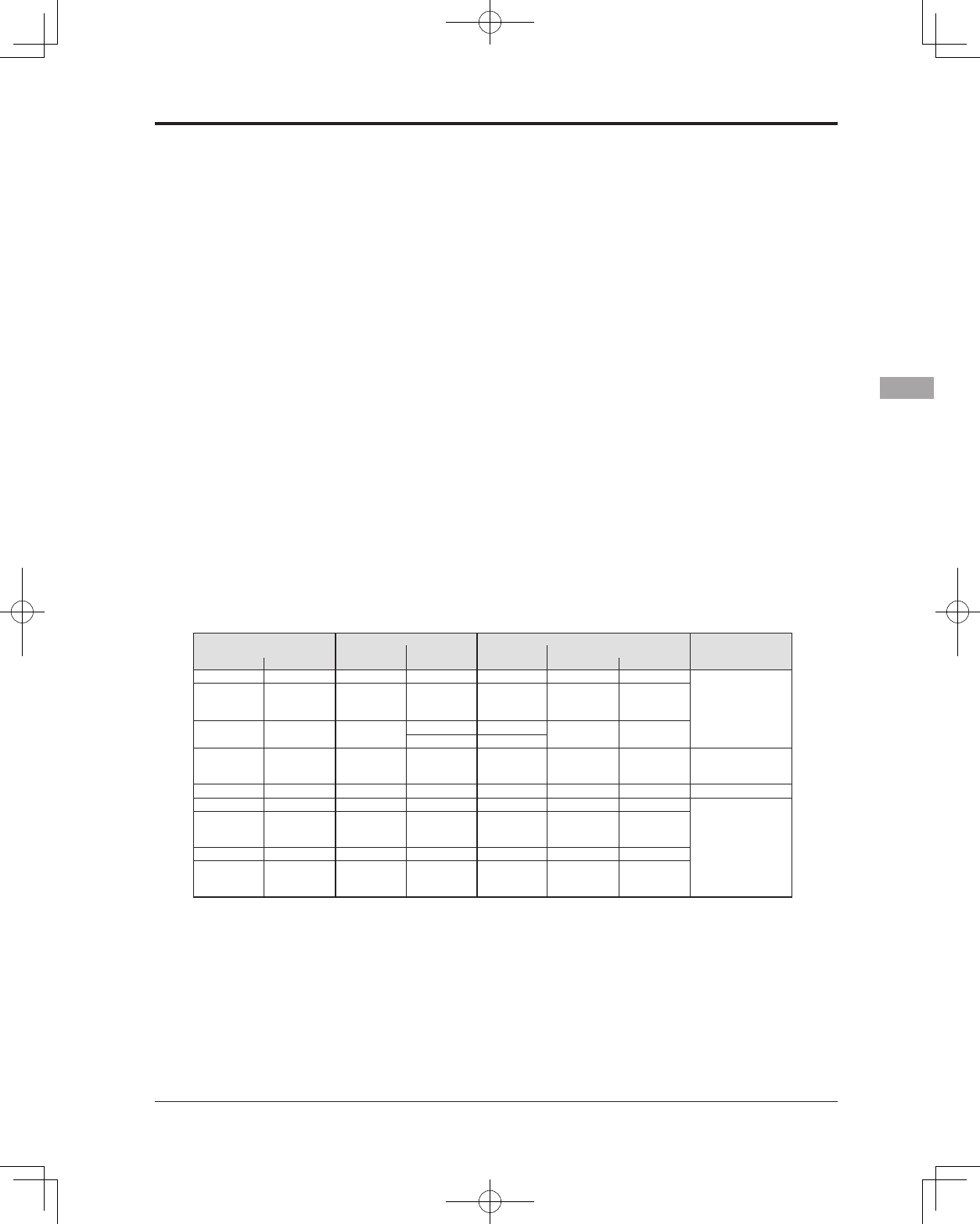
Corresponding types of transmitters and trainer mode settings:
Types of transmitters Instructor's transmitter settings Student's transmitter settings
System Type Trainer setting System Type Trainer setting Trainer Cords
Instructor Student Mod. mode CH mode Mod. mode CH mode Mod. mode
T14SG/T18MZ T14SG/T18MZ Arbitrary 14CH/16CH Arbitrary 14CH/16CH -
T12FG (FUTM4405)
and 9C (FUTM4415)
Trainer Cords
T14SG
T14MZ, FX-40,
T12Z, T12FG,
FX-30
Arbitrary 12CH PCM-G3
2.4G 12CH PPM
T14SG T8FG, FX-20 Arbitrary 12CH FASST-MLT2 - -
8CH FASST-MULT
T14SG
T10C, T9C,
T7C,T6EX,
T4EX
Arbitrary 8CH PPM - - T12FG (FUTM4405)
T14SG T10CG,T7C Arbitrary 8CH Arbitrary - - T12FG (FUTM4405)
T14SG T8J,T6J Arbitrary 8CH Arbitrary - -
T12FG (FUTM4405)
and 9C (FUTM4415)
Trainer Cords
T14MZ, FX-40,
T12Z, T12FG,
FX-30
T14SG Arbitrary 12CH Arbitrary 12CH -
T8FG, FX-20 T14SG Arbitrary 12CH Arbitrary 12CH -
T10C, T10CG,
T9C, T7C,
T7C,T8J
T14SG Arbitrary -Arbitrary 8CH -
52 <Functions of System Menu>
● Select the function name
and return to the System
menu by touching the
RTN button. Or the
HOME/EXIT button is
pushed.
<SensorTouch™>
RETURN
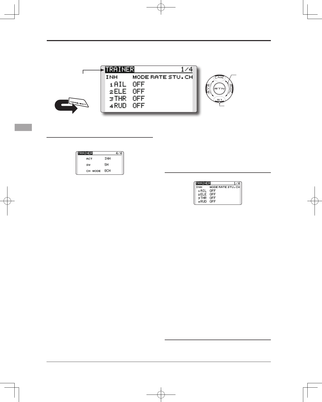
Mode and switch selection
1. Access the setup screen page 4 shown
below by touching the S1 button three times.
2. Move the cursor to the [ACT] or [12/8CH]
item and touch the RTN button to switch to
the data input mode.
3. Select the mode by scrolling the touch
sensor. The display blinks. Touch the RTN
button to change the mode. (To terminate
the mode change, touch the S1 button.)
"ACT": Enable operation by changing to [OFF]
or [ON].
"12/8 CH": When the student uses the T14SG,
T14MZ, T12Z, T12FG or FX-40, select [12CH].
Otherwise select [8CH].
If changing the trainer switch:
4. Move the cursor to the [SW] item and touch
the RTN button to access the switch setup
screen.
(See "Switch selection method" at the end of
this manual for selection method details.)
"SW": Select the desired switch.
Initial setting: SH
*The switch mode can also be selected when setting the ON
position on the switch setup screen. When [ALTERNATE
OFF] is selected, normal ON/OFF operation is performed.
When [ALTERNATE ON] is selected, the trainer function
is alternately turned on and off each time the switch is
operated. This allows alternate ON/OFF switching even
when a momentary switch (SH) is used.
● Select [TRAINER] in the System menu and enter the
setup screen shown below by touching the RTN
button.
Note: The trainer function won’t be turned
on unless the Instructor's transmitter receives
signals from the student's transmitter. Be
sure to confirm this after connecting your
trainer cable.
Operating mode selection
(Setup screen page 1-3)
1. Move the cursor to the [MODE] item of the
channel you want to change and touch the
RTN button to switch to the data input mode.
2. Select the mode by scrolling the touch
sensor. The display blinks. Touch the RTN
button to change the mode. (To terminate
the mode change, touch the S1 button.)
"MODE": Select the desired operation mode
for each channel.
NORM: The model is controlled by signals from the student
transmitter.
MIX mode: The model is controlled by signals from the
instructor and student transmitters. (Reset the student's
model data to the default condition.)
FUNC mode (function mode): The model is controlled by
signals from the student transmitter with the instructor 's
setting. (Reset the student's model data to the default
condition.)
OFF: Only the instructor side operates.
Adjusting the student's rate.
*This can be adjusted for students who may need lower rates
than a more experienced student.
Scrolling
● Moving cursor
● Selecting mode
● Adjusting value
● To next page
53
<Functions of System Menu>
1. Move the cursor to the [RATE] item of the
channel you want to change and touch the
RTN button to switch to the data input mode.
2. Adjust the rate by scrolling the touch sensor.
"RATE": Adjust the desired rate.
Setting range: 0~100%
Initial value: 100%
*When you want to reset the value to the initial state, touch
the RTN button for one second.
3. To end adjustment, touch the RTN button
and return to the cursor mode.
Changing the student's channel
*The setting above allows setting of the channel assignment
of student side when [MIX] or [FUNC] was selected.
1. Move the cursor to the [STU. CH] item of the
channel you want to change and touch the
RTN button to switch to the data input mode.
2. Select the channel by scrolling the touch
sensor. The display blinks. Touch the RTN
button to change the channel. (To terminate
the mode change, touch the S1 button.)
"STU. CH": Match the channel order of the
Instructor's and student's transmitter. This
function will help if both transmitters are in
different modes, or the Master has a different
wing type set up. The student can be set
to match the Master without any physical
changes being made.
54 <Functions of System Menu>
● Select the function name
and return to the System
menu by touching the
RTN button. Or the
HOME/EXIT button is
pushed.
<SensorTouch™>
RETURN
LCD contrast adjustment
1. Select "CONTRAST" and touch the RTN button
to switch to the data input mode and adjust
the contrast by scrolling the touch sensor.
"CONTRAST": Adjust the contrast to the
desired value while watching the screen
display.
Setting range: (Lighter) 0 to 15 (Darker)
Initial value: 5
*When you want to reset the value to the initial state, touch
the RTN button for one second.
2. Touch the RTN button to end adjustment and
return to the cursor mode.
Back-light brightness adjustment
1. Select "BRIGHTNESS" and touch the RTN
button to switch to the data input mode and
adjust the back-light brightness by scrolling
the touch sensor.
"BRIGHTNESS": Adjust the brightness to the
desired value while watching the screen
display.
Setting range: OFF, 1 to 20(Lighter)
Initial value: 10
*When you want to reset the value to the initial state, touch
the RTN button for one second.
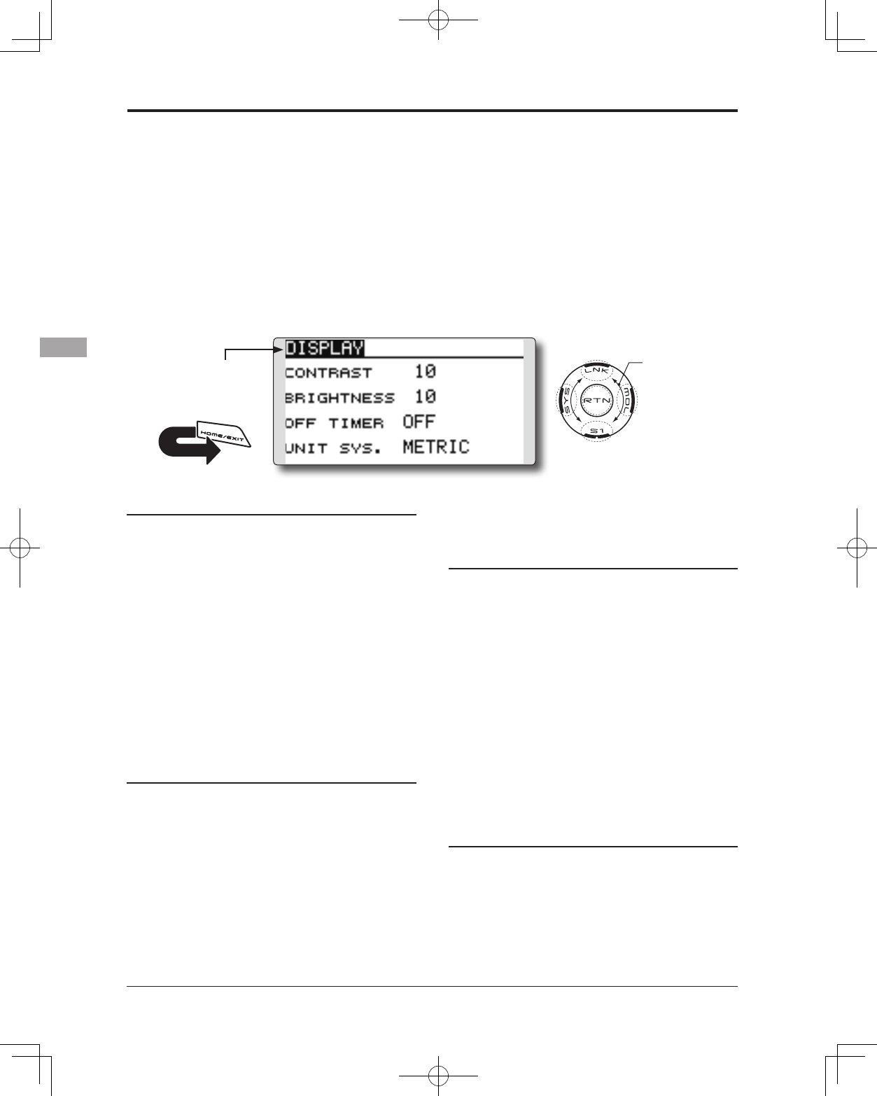
DISPLAY LCD and back-light adjustment, unit system
LCD contrast, back-light brightness and back-
light off-timer adjustment are possible:
Moreover, a display unit can be chosen from the
metric system or yard/pound.
2. Touch the RTN button to end adjustment and
return to the cursor mode.
Back-light off-timer
1. Select "OFF TIMER" and touch the RTN button
to switch to the data input mode and adjust
the back-light off-timer by scrolling the touch
sensor.
"OFF TIMER": Adjust the time when the back-
light turns off after operating the touch
sensor.
Setting range: 10 to 240 sec (each 10 sec),
OFF (always on)
Initial value: 10 sec
*When you want to reset the value to the initial state, touch
the RTN button for one second.
2. Touch the RTN button to end adjustment and
return to the cursor mode.
Unit system adjustment
1. Select "UNIT SYS." and touch the RTN button
to switch to the data input mode and adjust
the unit by scrolling the touch sensor.
Setting range: (METRIC) or (YARD/POUND)
2. Touch the RTN button to end adjustment and
return to the cursor mode.
● Select [DISPLAY] at the system menu and access
the setup screen shown below by touching the
RTN button.
Scrolling
● Moving cursor
● Adjusting value
55
<Functions of System Menu>
● Select the function name
and return to the System
menu by touching the
RTN button. Or the
HOME/EXIT button is
pushed.
<SensorTouch™>
RETURN
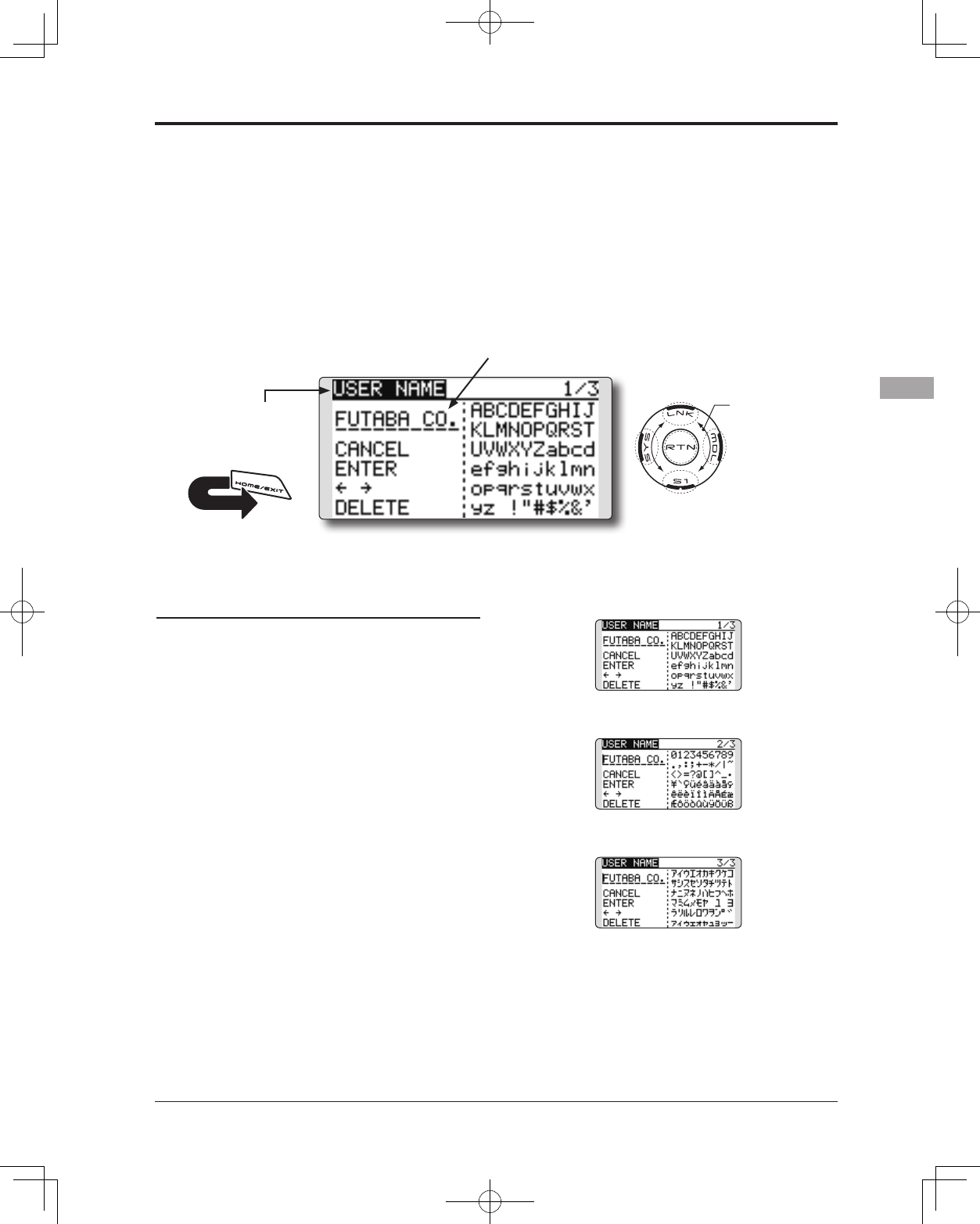
USER NAME User name registration
This function allows the modelers to change the
T14SG user name.
*A name of up to 10 characters can be entered as the user
name. Please note that a space is also counted as one
character.
User name registration
1. Change the user name as described below:
[Moving cursor in user name (candidate)]
Select [←] or [→], and touch the RTN button.
[Deleting a character]
When [DELETE] is selected and the RTN button
is touched, the character immediately after
the cursor is deleted.
[Adding a character]
When a character is selected from the
character list and the RTN button is touched,
that character is added at the position
immediately after the cursor.
*A name of up to 10 characters long can be entered as the
user name. (A space is also counted as 1 character.)
2. Upon completing the input, select [ENTER]
and touch the RTN button. (To terminate
input and return to the original state, select
[CANCEL] and touch the RTN button.)
(Character list 1/3)
(Character list 2/3)
(Character list 3/3)
● Select [USER NAME] at the System menu and
access the setup screen shown below by touching
the RTN button.
User name (candidate)
Scrolling
● Moving cursor
56 <Functions of System Menu>
● Select the function name
and return to the System
menu by touching the
RTN button. Or the
HOME/EXIT button is
pushed.
<SensorTouch™>
RETURN
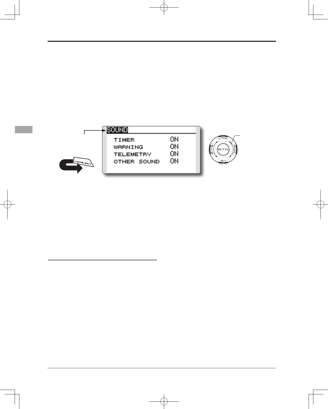
SOUND Turns off the buzzer.
The warning sound and other sounds of the
T14SG transmitter can be turned off.
*When “WARNING” was set to OFF, the no operation alarm
(30 minutes), mixing warning sound, and low battery alarm
sounds also turned off.
● Select [SOUND] at the system menu and access
the setup screen shown below by touching the
RTN button.
On/off operation
1. Move the cursor to the [TIMER][WARNING]
or [OTHER SOUND] item and touch the RTN
button to switch to the data input mode.
2. Select the ON or OFF by scrolling the touch
sensor.
*The display blinks.
3.Touch the RTN button.
Scrolling
● Moving cursor
● Selecting mode
57
<Functions of System Menu>
● Select the function name
and return to the System
menu by touching the
RTN button. Or the
HOME/EXIT button is
pushed.
<SensorTouch™>
RETURN
Operation direction reversal method
1. Select [H/W REVERSE] and access the setup
screen shown below by touching the RTN
button.
2. Move the cursor to the item corresponding
to the H/W (hardware) you want to reverse
and touch the RTN button to switch to the
data input mode.
3. Select the mode by scrolling the touch
sensor. The display blinks. When the RTN
button is touched, the operation direction is
reversed. (To terminate the mode change,
touch the S1 button.)
"NORM": Normal operation direction
"REV" : Operation direction is reversed.
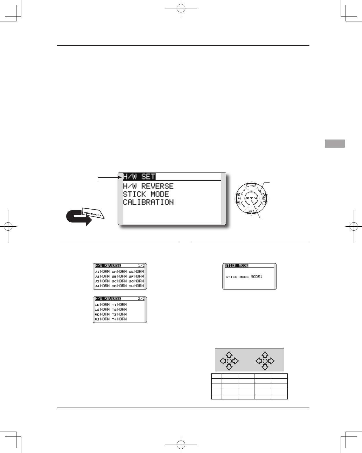
H/W SETTING Hardware reverse and stick mode
H/W reverse
This function reverses the operation direction of
the sticks, switches, trimmer levers, and knobs.
Note: This setting reverses the actual operation
signal, but does not change the display
indicators. Use the Normal mode as long as
there is no special reason to use the Reverse
mode.
Stick mode
This function changes the stick mode of
transmitter.
Note: This will not change the throttle ratchet,
etc. Those are mechanical changes that
must be performed by a Futaba service
center.
Note: After changing the mode, these changes
are only applied to new models. It is not
applied to an existing model.
Stick calibration
J1-J4 stick correction can be performed.
● Select [H/W SET] at the system menu and access
the setup screen shown below by touching the
RTN button.
Changing stick mode
1.Select [STICK MODE] and access the setup
screen shown below by touching the RTN
button.
2. Move the cursor to the "STICK MODE" item
and touch the RTN button to switch to the
data input mode.
3. Select the mode. The display blinks. When
the RTN button is touched, the stick mode is
changed. (To terminate the mode change,
touch the S1 button.)
(J1)
(J2)
(J4)
(J3)
Mode J1 J2 J3 J4
1 Aileron Throttle Elevator Rudder
2 Aileron Elevator Throttle Rudder
3 Rudder Throttle Elevator Aileron
4 Rudder Elevator Throttle Aileron
●Access setup screen
Scrolling
● Moving cursor
58 <Functions of System Menu>
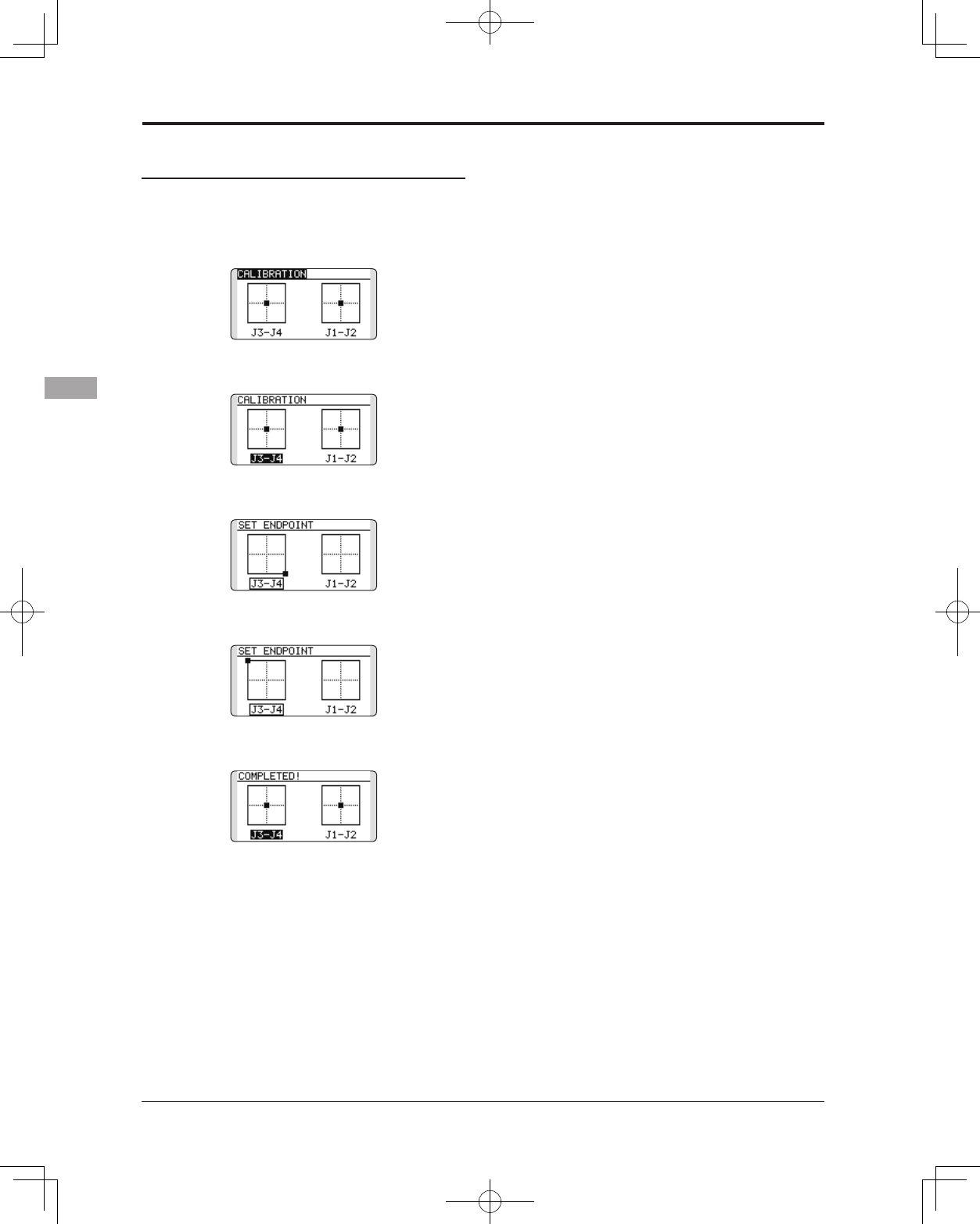
Stick calibration method
*J3 and J4 correction is described below. J1 and J2
corrections are performed using the same procedure.
1.Select [CALIBRATION] and access the setup
screen shown below by touching the RTN
button.
2.Move the cursor to the J3-J4 button and
touch the RTN button.
3.Move the J3 or J4 sticks to the neutral position
and press the RTN button for one second.
4.Set the J3 and J4 sticks fully to the bottom
right and wait until the buzzer sounds.
5.Set the J3 and J4 sticks fully to the top left and
wait until the buzzer sounds.
6.The above completes the correction
operation. Operate and check if stick
correction was performed normally.
59
<Functions of System Menu>
● Select the function name
and return to the System
menu by touching the
RTN button. Or the
HOME/EXIT button is
pushed.
<SensorTouch™>
RETURN
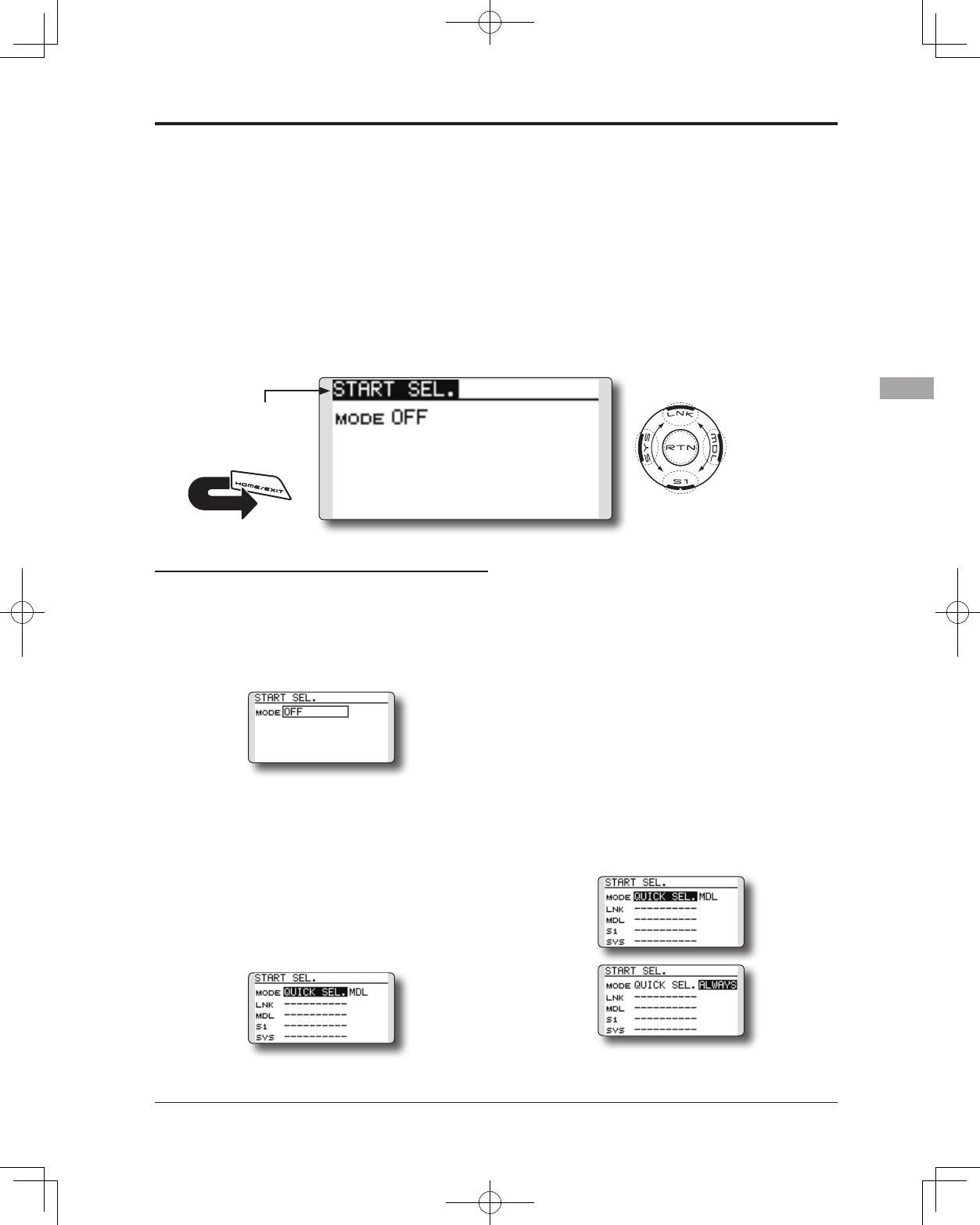
Setting Up and Adjusting the Quick Select Models
1. The Start Selection (START SEL.) menu is
accessed through the T14SG System Menu.
Turn the transmitter ON and then press the
SYS (System) button two times. Use the
SensorTouch™ to highlight the Start Selection
(START SEL.) and then press the Return (RTN)
button to conrm the selection.
2.The Start Selection (START SEL.) menu option
defaults to OFF meaning that Quick Select
and Model Select are not applicable. To
activate the Quick Select or Model Select,
use the SensorTouch to scroll to the OFF
setting as denoted in the image. With the
OFF indication highlighted, press the Return
(RTN) button and rotate the SensorTouch once
again to scroll amongst the options. With the
Quick Select (QUICK SEL.) indicated, press the
Return (RTN) button once again to make the
desired selection as indicated.
Quick Select Activation:
With the Quick Select (QUICK SEL.) option
activated, there are two additional options available
for customization; ALWAYS and MDL (Model).
These options determine if/when the Quick Select
information will appear on-screen. ALWAYS,
as the name suggests, indicates that each time
the transmitter is powered-up, the Quick Select
information will appear on-screen. The MDL
(Model) setting indicates that the Quick Select
information will appear on-screen only when
the MDL button is pressed simultaneously as the
transmitter is turned ON. With the Quick Select
mode highlighted, use the SensorTouch to move to
the activation setting options. Model (MDL) is the
default setting. Press the Return (RTN) button to
bring forth the options, then scroll to the ALWAYS
setting using the SensorTouch pad. Press the Return
(RTN) button once again to nalize the selection.
START SEL is a function which starts and can
perform a model selection immediately.
Each time, it is convenient for the modeler
which is enjoying two or more models by one of a
transmitter.
Quick Select Screen
As the name suggests, the Quick Model Select
Function enables the modeler to change the
selected models rapidly each time the transmitter is
turned ON. With a few quick touches, it is possible
to change models whereas before it would require
a multi-step process. The T14SG stores up to four
models in the Quick Select offerings.
Model Select Screen
When the transmitter is turned on, it will open to
the Model Selection Screen immediately.
START SEL. Immediately, a model selection can be performed
60 <Functions of System Menu>
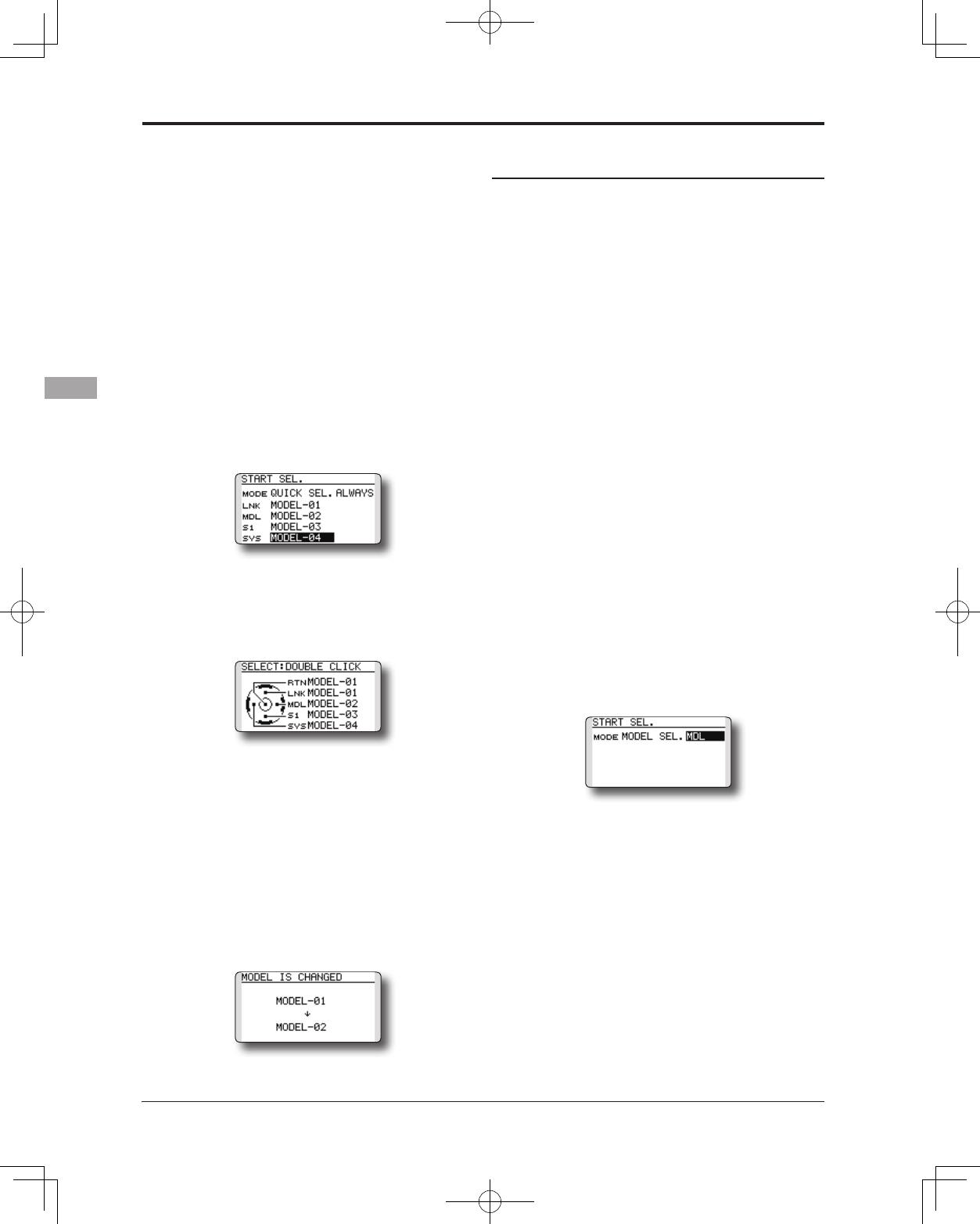
Assigning models to the sensor buttons:
There are four sensors/buttons that correspond
with the SensorTouch: Link (LNK), Model (MDL)
System (SYS) and S1. As such, it is possible to offer
up to four models available through the Quick Select
function. We suggest using the models that you y
most often.
1. Use the SensorTouch, scroll to the desired
sensor/button for the rst model; for example,
Link (LNK).
2. With the input next to the desired sensor
highlighted, press the Return (RTN) button one
time.
3. Using the SensorTouch, scroll through the
available models. To select the desired
model, press the Return (RTN) button.
4. Repeat as desired for the remaining sensors.
Using the sensors to select the model:
1. Turn ON the transmitter, activating the
Quick Select screen. If Model (MDL) has
been selected, please be sure to press the
Model (MDL) sensor when powering up the
transmitter.
* Please note: Even if the Quick Select function is active, the
Power Mode screen will appear when the transmitter is turned
ON while simultaneously pressing the Return (RTN) button.
2. To select the model assigned to a particular
sensor, double-click the desired sensor. For
example, MODEL- 03 is assigned to S1, double-
click S1 to bring forth all settings, etc. for Model
-03. The T14SG offers an audible and visual
conrmation as the selected model memory is
changed accordingly.
* If the Return (RTN) button is double-clicked, the T14SG the
current model is selected as indicated on the display. That is,
the model that was used prior to the last time the transmitter
was turned OFF.
Model Select Screen
This allows the Model Select screen to be accessed
immediately upon turning ON the transmitter.
* Please note: this function cannot be utilized at the same time
as the Quick Select function. If more than four models are
own regularly, we suggest that the Model Select function be
utilized as it will save time when selecting the desired aircraft.
If four, or fewer, models are own, the Quick Select option
would be the best choice.
* Please note: the Model Select function does not allow access
to the RENAME, COPY or DELETE options. To utilize one
of these options, please access the Model Select screen in
the typical manner as described in the complete instruction
manual.
1.The Start Selection (START SEL.) menu is
accessed through the T14SG’s System Menu.
Turn the transmitter ON and then press the
SYS (System) button two times. Use the
SensorTouch™ to highlight the Start Selection
(START SEL.) and then press the Return (RTN)
button to conrm the selection.
2. The Start Selection (START SEL.) menu option
defaults to OFF meaning that Quick Select
and Model Select are not applicable. To
activate the Quick Select or Model Select, use
the SensorTouch to scroll to the OFF setting as
denoted in the image. With the OFF indication
highlighted, press the Return (RTN) button and
rotate the SensorTouch once again to scroll
to the Model Select (MODEL SEL.). Press the
Return (RTN) button once again to activate
Model Select as indicated.
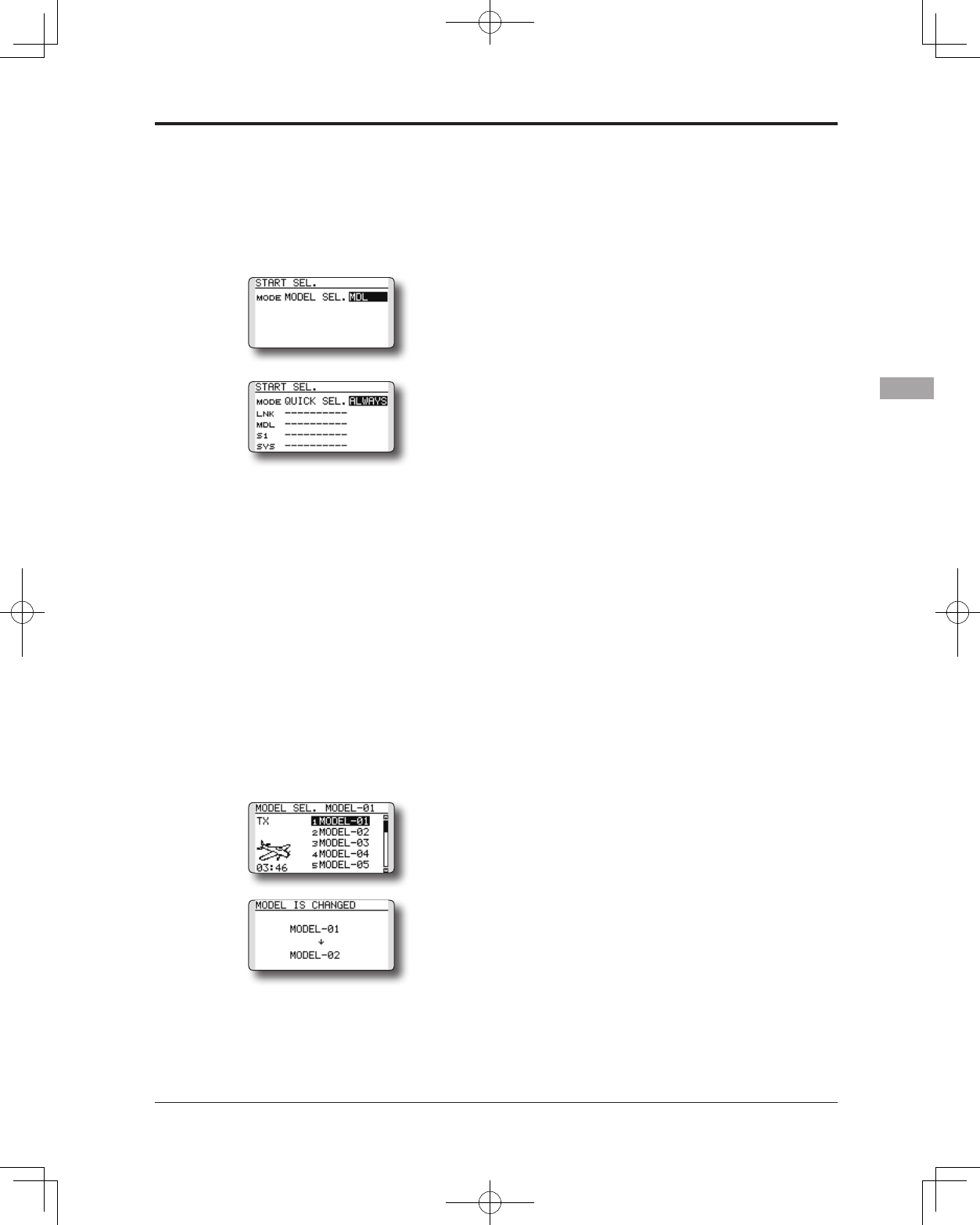
Model Select Activation:
With the Model Select (MODEL SEL.) option
activated, there are two additional options available
for customization; ALWAYS and MDL (Model).
These options determine if/when the Model Select
information will appear on-screen. ALWAYS,
as the name suggests, indicates that each time
the transmitter is powered-up, the Model Select
information will appear on-screen. The MDL
(Model) setting indicates that the Model Select
information will appear on-screen only when
the MDL button is pressed simultaneously as the
transmitter is turned ON.
With the Model Select mode highlighted, use the
61
<Functions of System Menu>
SensorTouch to move to the activation setting
options. Model (MDL) is the default setting. Press
the Return (RTN) button to bring forth the options,
then scroll to the ALWAYS setting using the
SensorTouch pad. Press the Return (RTN) button
once again to nalize the selection.
Using the Model Select Function:
1. Turn ON the transmitter, activating the
Model Select screen. If Model (MDL) has
been selected, please be sure to press the
Model (MDL) sensor when powering up the
transmitter.
*Please note: Even if the Model Select function is active, the
Power Mode screen will appear when the transmitter is turned
ON while simultaneously pressing the Return (RTN) button.
2. The SensorTouch is used to select amongst
the on-screen models. The current model
will automatically be highlighted when the
transmitter is turned ON. If a different model is
desired, use the SensorTouch to scroll through
the available options; each highlighted
accordingly. Again, to select a model,
press the Return (RTN) button accordingly.
The T14SG offers an audible and visual
conrmation as the selected model memory is
changed.
62 <Functions of System Menu>
● Select the function name
and return to the System
menu by touching the
RTN button. Or the
HOME/EXIT button is
pushed.
<SensorTouch™>
RETURN
●Lock release
Every lock function's touch [ 1 second
or more ] of S1 button will release the
lock.
●Lock release
Every lock function's touch [ 1 second
or more ] of HOME/EXIT button will
release the lock.
● Manual lock
If S1 button is touched 1 second
or more from a HOME screen, a
SensorTouch locks manually.
● Manual lock
If HOME/EXIT button is touched 1
second or more from a HOME screen,
a SensorTouch locks manually.
●Display of a lock
If locked, there will be sound and the
icon of a key will come out.
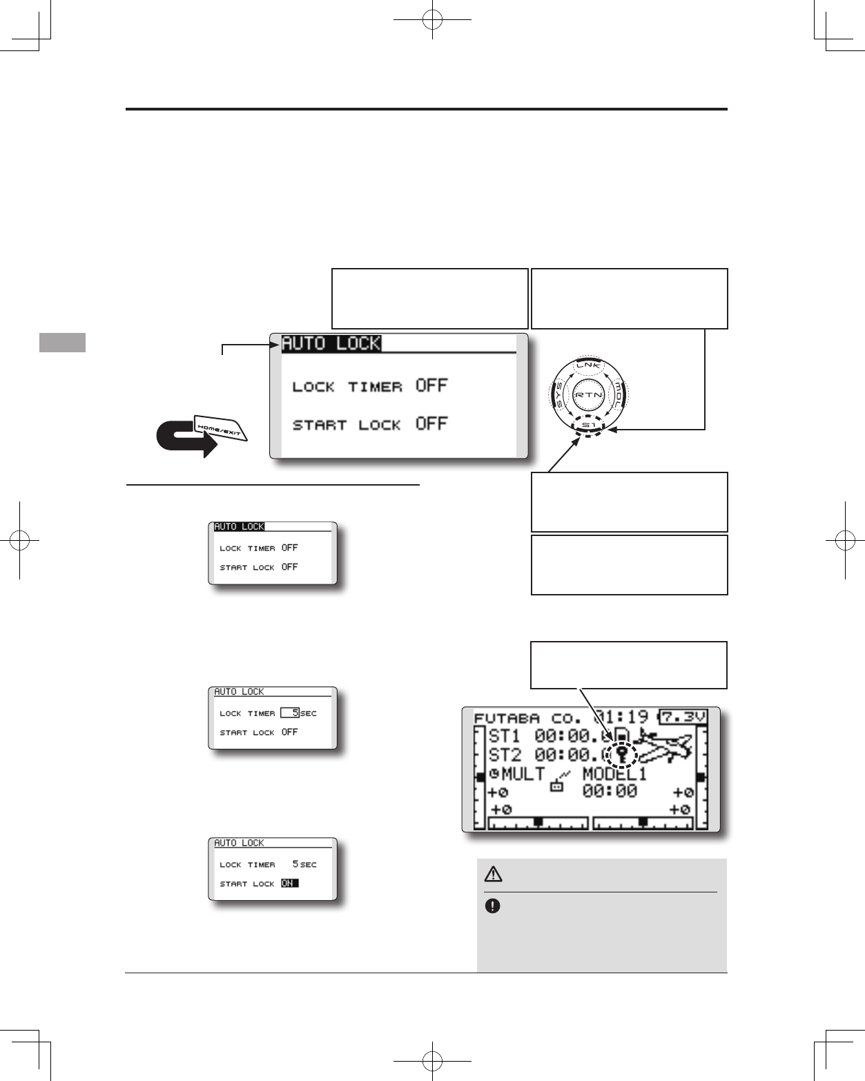
Auto lock method
1. Open the Auto lock screen in the system
menu.
2. Adjust the activation timer for the Auto
Lock function. The timer will begin counting
immediately when the HOME screen is not
used. The timer is adjustable in one second
increments up to 30 seconds. If the timer
value is OFF, this function is not applicable.
3.The Start Lock setting will, if enabled,
automatically lock the T14SG when the
transmitter is powered up. To allow access to
the transmitter's functions, press and hold the
S1 key for one second.
*If neither the Lock Timer or Start Lock functions are active
(OFF), then the key lock remains even if the power is turned off.
*If the Lock Timer is enabled and the Start Lock is off, the key
lock status is canceled each time the T14SG is turned on.
The Auto Lock function makes it possible to lock
the transmitter to prevent any unwanted input from
your hands while ying.
The auto lock function can be set in two ways.
LOCK TIMER
Auto Lock functions automatically when there is
no operation from the HOME screen display for a
chosen number of seconds.
START LOCK
Auto Lock functions automatically when the
model changes or power is turned on.
*To temporarily allow access to the T14SG programming
press and hold the S1 or HOME/EXIT bitton for one second.
Please note, the Auto Lock function timer will resume
immediately once again.
AUTO LOCK The automatic lock function of two kinds of SensorTouch
Danger
It is recommended to Lock the
SensorTouch during ight, to prevent
any accidental touches which could
change settings and cause an accident.
63
<Functions of System Menu>
● Select the function name
and return to the System
menu by touching the
RTN button. Or the
HOME/EXIT button is
pushed.
<SensorTouch™>
RETURN
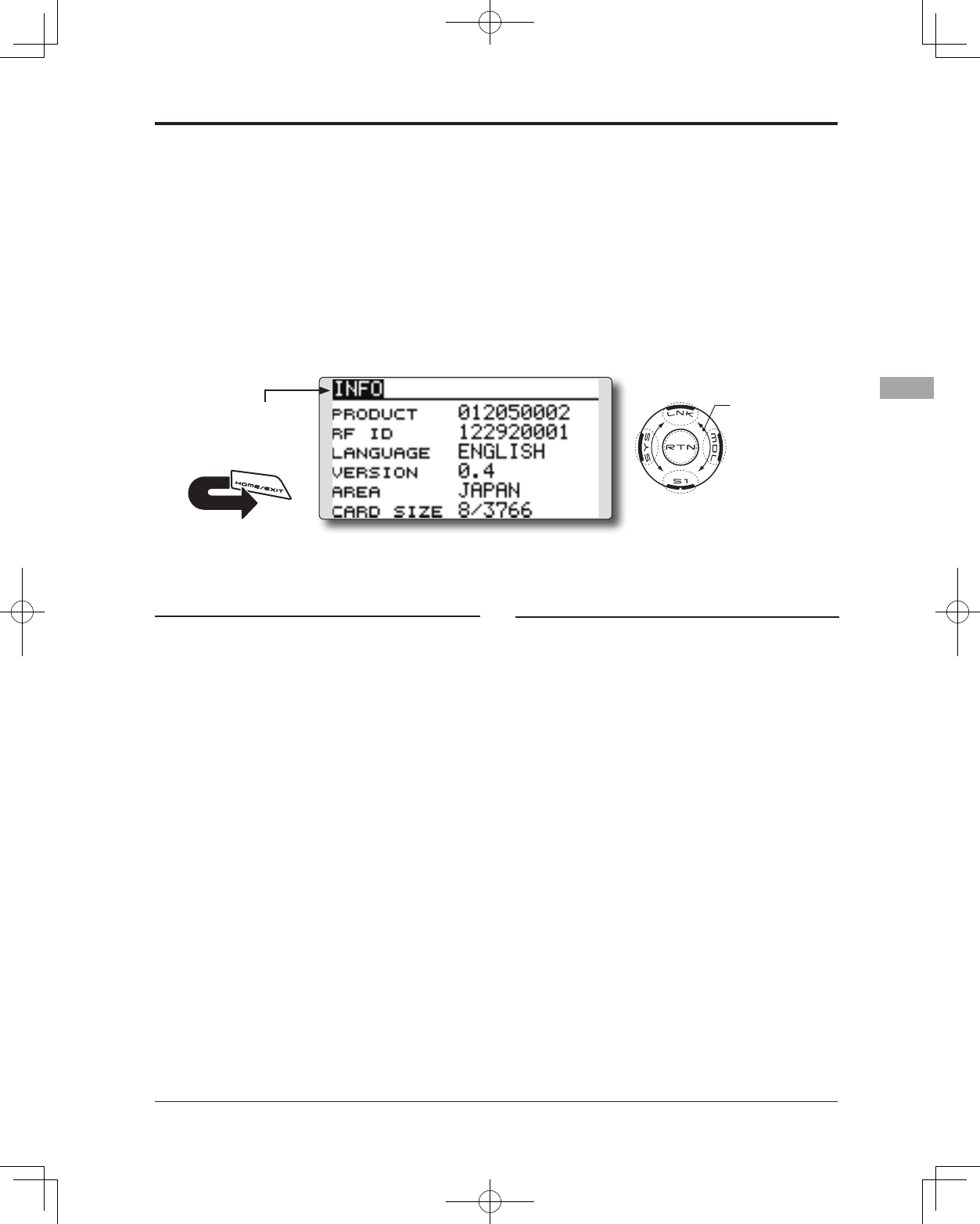
INFO Displays the program version, SD card information, and product ID.
The T14SG system program version information,
SD card information (current and maximum
number of model data and other les), and product
ID are displayed on the Information screen.
*When the SD card is not inserted, the SD card information is
not displayed.
The language displayed in home, menu, and
setup screen is selectable.
● Select [INFO] at the system menu and access the
setup screen shown below by touching the RTN
button.
Information
"PRODUCT": Product ID number
"RF ID": RF ID number
"LANGUAGE": The language used in T14SG
"VERSION": T14SG system program version
information
"AREA": Area which can use T14SG
"CARD SIZE": Current/Maximum number of
model data and other les (SD card)
Language selection
1. Move the cursor to the "LANGUAGE" item
and touch the RTN button to switch to the
data input mode.
2. Change the language by scrolling the touch
sensor. The display blinks. When the RTN
button is touched, the language is changed.
(To terminate the change, turn the EDIT dial
or push the S1 button.)
Scrolling
● Moving cursor
● Selecting mode
64 <Functions of System Menu>
● Select the function name
and return to the System
menu by touching the
RTN button. Or the
HOME/EXIT button is
pushed.
<SensorTouch™>
RETURN
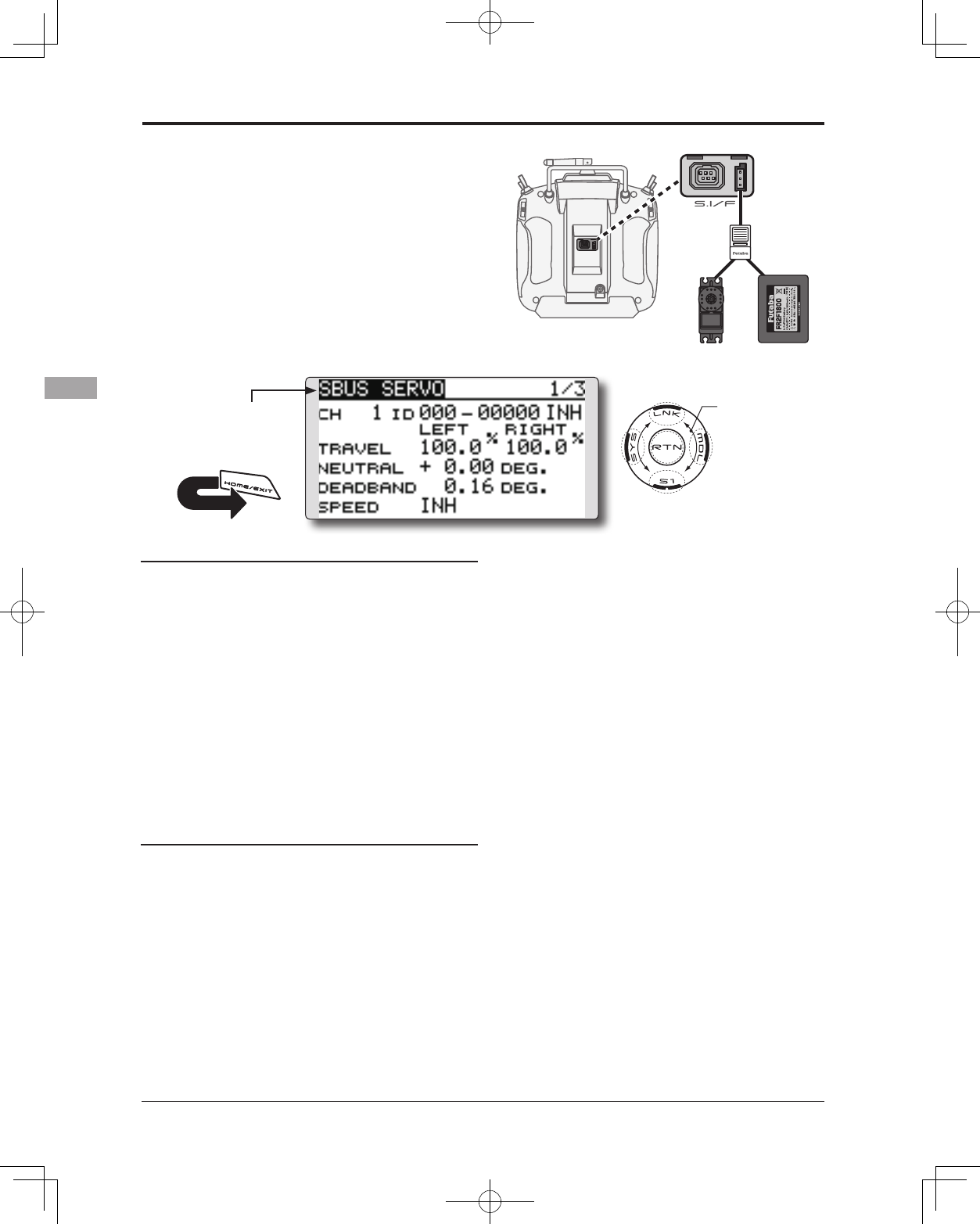
SBUS servo setting.
An S.BUS servo can memorize the channel
and various settings you input. Servo setting
can be performed on the T14SG screen by
wiring the servo as shown in the figure.
● Select [SOUND] at the system menu and access
the setup screen shown below by touching the
RTN button.
Scrolling
● Moving cursor
● Selecting mode
Servo ID number
Individual ID numbers are memorized for your
S.BUS(2) servos in your T14SG. When a servo is
used, the servo ID number is automatically read by
the transmitter. If you use multiple S.BUS(2) servos
and do not want to change the settings on all that are
mounted in a fuselage, only the desired servo in the
group can be set by entering the ID of that specic
servo.
* S9070SB cannot be arranged by T14SG.
* With some S.BUS(2) servos, there are some functions with
cannot be used. If a function cannot be used, the display screen
will change.
(Only the function which can be used by a servo is displayed.)
* After reading completion, with connection of the above
gure, if a stick is moved, the test of operation of the servo
can be operated and carried out.
Procedure for changing S.BUS servo setting
1. Select [SBUS SERVO] of the System Menu.
2. Wire the servo as shown in the gure above.
3. Press [RECALL] on page 3(S1 is pushed twice).
The ID and current setting of that servo are
displayed. ([RECALL] is chosen ⇒RTN is
pushed ⇒RTN is pushed for 1 second)
4. When multiple servos are connected change
[INH] at the right side of the ID number on the
screen to [ACT] and enter the ID of the servo
you want to set.
5. Set each item. (Please see the next page.)
6. Press [WRITE] on page 3([WRITE] is
chosen ⇒RTN is pushed ⇒RTN is pushed for 1
second). The settings are changed.
Push [INIT.], if you would like to initialize a
setup of a servo. ([INIT.] is chosen ⇒RTN is
pushed ⇒RTN is pushed for 1 second)
S.BUS/S.BUS2
Servo
Battery
T14SG
3-way hub
or
Y-harnesses
SBUS SERVO
65
<Functions of System Menu>
S.BUS Servo Description of function of each parameter
*There are a function which can be used according to the kind of servo, and an impossible function.
• ID
Displays the ID of the servo whose parameters are to be read. It cannot be changed.
• Channel
Channel of the S.BUS system assigned to the servo. Always assign a channel before use.
• Reverse
The direction in which the servo rotates can be changed.
• Servo type
When “Retractable” is selected and the servo has been continuously stopped for 30 seconds, the dead band
expands and unnecessary hold current due to external force is eliminated. When a new control signal enters,
normal operation is resumed. When using the servo as a landing gear servo, select “Retractable”. Also adjust the
servo travel to match the landing gear movement range.
• Soft Start
Restricts operation in the specified direction the instant the power is turned on. By using this setting, the first initial
movement when the power is turned on slowly moves the servo to the specified position.
• Stop Mode
The state of the servo when the servo input signal is lost can be specified. The "Hold" mode setting holds the
servo in its last commanded position even if using AM or FM system.
• Smoother
This function changes smoothness of the servo operation relative to stick movement changes. Smooth setting is
used for normal flight. Select the "OFF" mode when quick operation is necessary such as 3D.
• Neutral Offset
The neutral position can be changed. When the neutral offset is large value, the servo's range of travel is restricted
on one side.
• Speed Control
Speeds can be matched by specifying the operating speed. The speed of multiple servos can be matched without
being affected by motor fluctuations. This is effective for load torques below the maximum torque.
However, note that the maximum speed will not be exceed what the servo is capable of even if the servos
operating voltage is increased.
• Dead band
The dead band angle at stopping can be specified.
[Relationship between dead band set value and servo operation]
Small → Dead band angle is small and the servo is immediately operated by a small signal change.
Large → Dead band angle is large and the servo does not operate at small signal changes.
(Note) If the dead band angle is too small, the servo will operate continuously and the current consumption will
increase and the life of the servo will be shortened.
• Travel Adjust
The left and right travels centered about the neutral position can be set independently.
• Boost
The minimum current applied to the internal motor when starting the servo can be set. Since a small travel does
not start the motor, it essentially feels like the dead band was expanded. The motor can be immediately started by
adjusting the minimum current which can start the motor.
[Relationship between boost set value and servo operation]
Small → Motor reacts to a minute current and operation becomes smooth.
Large → Initial response improves and output torque increases. However, if the torque is too large, operation will
become rough.
66 <Functions of System Menu>
• Boost ON/OFF
OFF : It is the boost ON at the time of low-speed operation.(In the case of usual)
ON : It is always the boost ON.(When quick operation is hope)
• Damper
The characteristic when the servo is stopped can be set.
When smaller than the standard value, the characteristic becomes an overshoot characteristic. If the value is
larger than the standard value, the brake is applied before the stop position.
Especially, when a large load is applied, overshoot, etc. are suppressed by inertia and hunting may occur,
depending on the conditions. If hunting (phenomena which cause the servo to oscillate) occurs even though the
Dead Band, Stretcher, Boost and other parameters are suitable, adjust this parameter to a value larger than the
initial value.
[Relationship between damper set value and servo operation]
Small → When you want to overshoot. Set so that hunting does not occur.
Large → When you want to operate so that braking is not applied. However, it will feel like the servo response has
worsened.
(Note) If used in the hunting state, not only will the current consumption increase, but the life of the servo will also
be shortened.
• Stretcher
The servo hold characteristic can be set. The torque which attempts to return the servo to the target position
when the current servo position has deviated from the target position can be adjusted.
This is used when stopping hunting, etc., but the holding characteristic changes as shown below.
[Relationship between stretcher and servo operation]
Small → Servo holding force becomes weaker.
Large → Servo holding force becomes stronger.
(Note) When this parameter is large, the current consumption increases.
• Buzzer
When the power supply of a servo is previously turned on at the time of a power supply injection without taking
transmit of a transmitter, the buzzer sound of about 2.5 Hz continues sounding from a servo.
(Even when the transmit of a transmitter is taken out previously, a buzzer becomes until the signal of a servo is
outputted normally, but it is not unusual.)
The transmitter has been turned OFF ahead of a servo power supply → The buzzer sound of about 1.25 Hz
continues sounding as servo power supply end failure alarm.
(Do not insert or remove the servo connector while the receiver power is ON. A buzzer may sound
by incorrect recognition.)
* Buzzer sound is generated by vibrating the motor of a servo.
Since current is consumed and a servo generates heat, please do not operate the number more than needed or
do not continue sounding a buzzer for a long time.
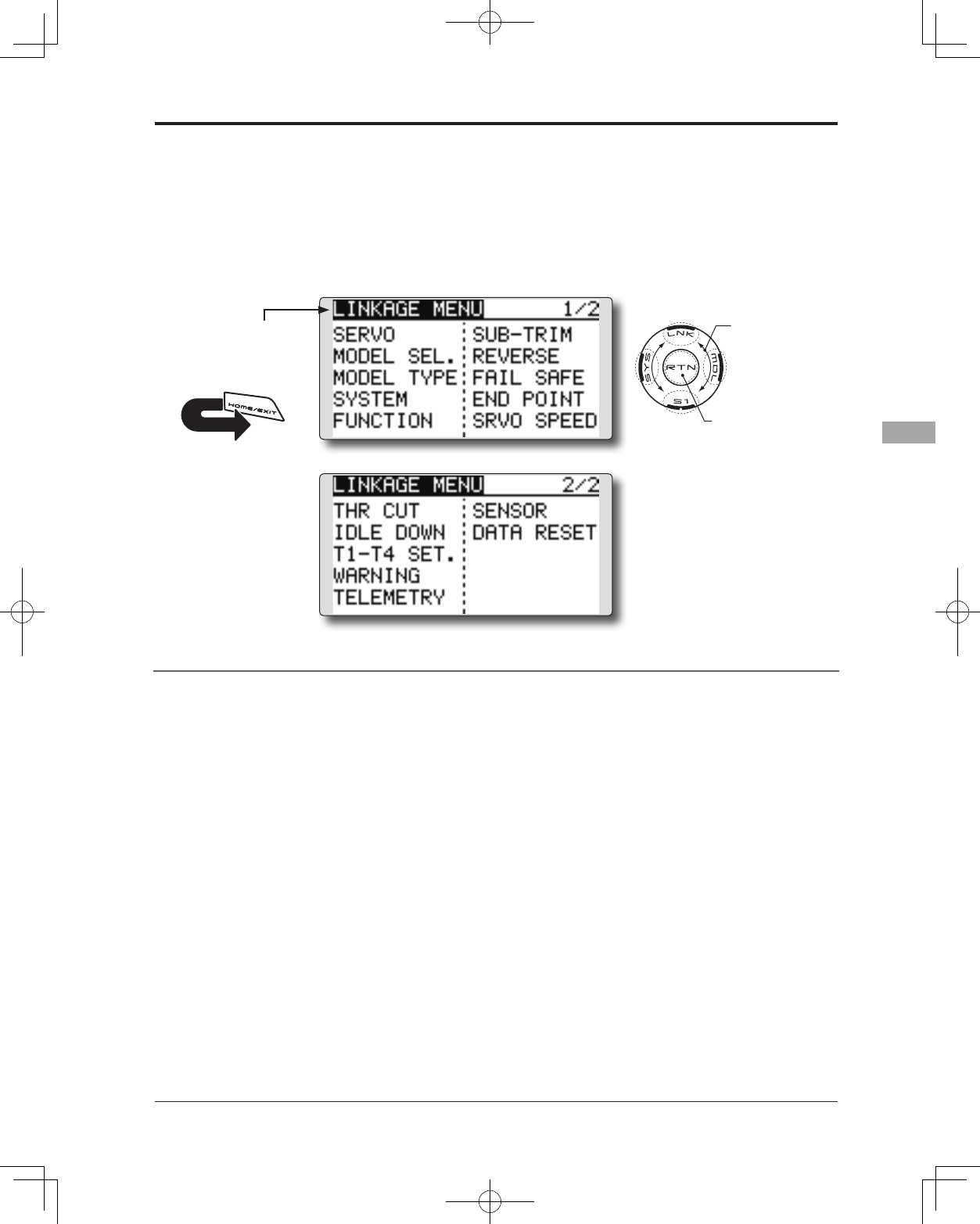
67
<Functions of Linkage Menu>
FUNCTIONS OF LINKAGE MENU
The Linkage Menu is made up of functions
which perform model addition, model type
selection, system type, end point setting, and other
model basic settings.
The functions which can be selected depend on
the model type. A typical menu screen is shown
below.
*The display screen is an example. The
screen depends on the model type.
Linkage Menu functions table
[SERVO]: Displays the servo test and operation position
[MODEL SEL]: Model addition, call, deletion, copy, model name setting
[MODEL TYPE]: Model type, wing type, swash type, etc. selection
[SYSTEM]: System mode selection, link of a transmitter and receiver, area mode selection
[FUNCTION]: Channel assignment of each function can be changed
[SUB-TRIM]: Adjusts the neutral position of each servo
[REVERSE]: Reverses the servo travel direction
[FAIL SAFE]: Fail safe function and battery fail safe function setting
[END POINT]: Servo travel adjustment and limit setting
[SERVO SPEED]: Speed setup of a servo
[THR CUT]: Stops the engine safely and easily (airplane and helicopter only)
[IDLE DOWN]: Lowers the idle speed of the engine (airplane only)
[SWASH RING]: Limits the swash plate travel to within a xed range. (helicopter only)
[SWASH]: Swash AFR and linkage correction function (helicopter only)
[T1-T4 SET.]: Control step amount and mode selection of the digital trim
[WARNING]: Mixing warning normal reset
[TELEMETRY]: Displays various data sent from the receiver.
[SENSOR]: Various telemetry sensors setting
[DATA RESET]: Model memory set data reset
● Access the Linkage menu shown below by
tapping the LNK button two times.
● Select the function name
and return to the Linkage
menu by touching the
RTN button. Or a HOME/
EXIT button is pushed.
<SensorTouch™>
● Select the function you want to set and call
the setup screen by touching the RTN button.
●Calling setup screen
Scrolling
● Moving cursor
RETURN
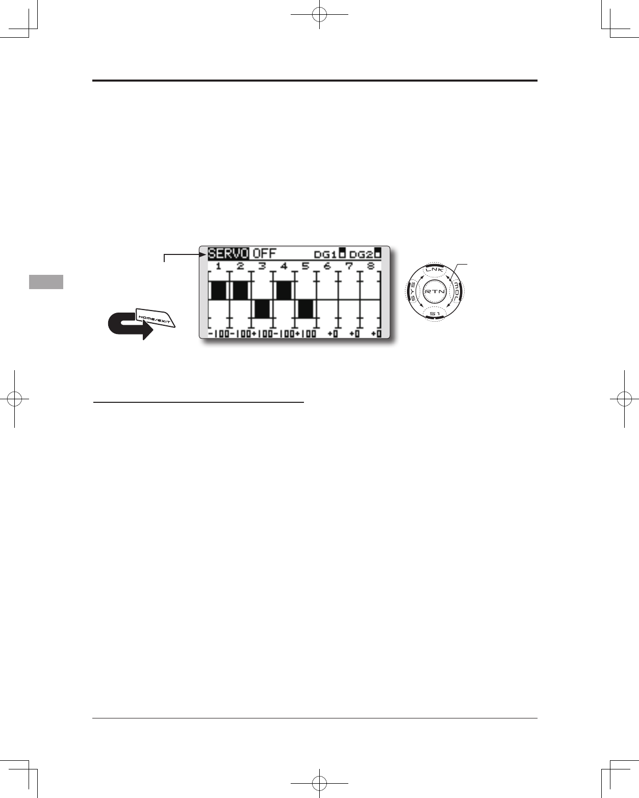
68 <Functions of Linkage Menu>
● Select the function name
and return to the Linkage
menu by touching the
RTN button. Or the
HOME/EXIT button is
pushed.
<SensorTouch™>
RETURN
SERVO MONITOR Servo Test & Graph Display / Displays servo positions.
This is used for testing servo movement.
“Moving Test” (repetition mode) and “Neutral
Test” (xed position mode) are available.
The “Neutral Test” is good for finding the
neutral position of a servo horn.
In order to prevent any potential difficulties,
the servo test function will be inoperable, or
inaccessible, under certain conditions. Specically,
the Servo Test function is not operational if the
Throttle Cut is ON in either airplane or helicopter
modes; or if the Throttle Hold is ON in Helicopter
mode.
● Select [SERVO] in the Linkage menu and access
the setup screen shown below by touching the
RTN button.
● A [U.MENU/MON.] button is pushed once from a
home screen.
Servo test operation
1. Move the cursor to the [OFF] item and touch
the RTN button to switch to the data input
mode.
Select the test mode by scrolling the touch
sensor and touch the RTN button. The display
blinks. Touch the RTN button to change the
mode. (To terminate mode change, touch
the S1 button.)
[MOVING]: Mode which repeats operation of
each servo
[NEUTRAL]: Mode which locks each servo in
the neutral position
2. Move the cursor to the [MOVING] or
[NEUTRAL] item and touch the RTN button to
switch to the data input mode.
Select the [OFF] by scrolling the touch sensor
and touch the RTN button. Testing is stopped.
Scrolling
● Moving cursor
● Selecting mode
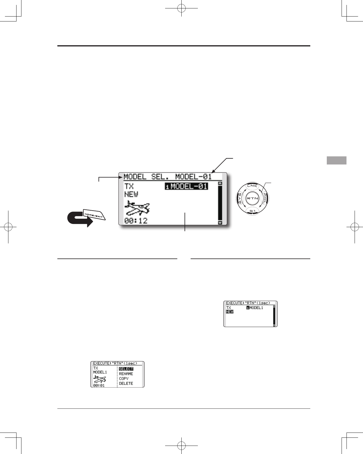
69
<Functions of Linkage Menu>
● Select the function name
and return to the Linkage
menu by touching the
RTN button. Or the
HOME/EXIT button is
pushed.
<SensorTouch™>
RETURN
MODEL SELECT The Model Selection function performs model addition, selection,
deletion, copy, and model name setting.
This function is used to load the settings of the
desired model into the T14SG’s memory.
The settings may be selected from either the
transmitter’s internal memory or an SD card.
Remember that up to 30 model memories are available
in the transmitter.
The name of the model stored in the transmitter and
the SD card may be changed. This can be very useful
to tell different models settings apart. Each model name
can be as long as 10 characters, and the model name
always appears in the display screen.
The Copy function is used to copy parameters,
settings, etc. from one model data into a second
memory. It may be used for getting a head-start on
setting up models with almost the same settings (only
differences need to be modied, instead of entering the
complete model from scratch). Also, this function may
be used to make a backup copy of a model setup before
any changes are made.
*T14SG can use the model data of T8FGS for SD card,
copying it. However, the model data of T14SG cannot be
used by T8SG (S).
Model selection
*Model data saved on the transmitter memory other than the
model currently used can be selected.
1. Move the cursor to the save destination
display ("TX" or "CARD") and touch the RTN
button to switch to the data input mode.
Select the save destination by scrolling the
touch sensor and touch the RTN button.
[TX]: Transmitter memory
[CARD]: SD card
2. After moving the cursor to the desired model
in the model list, touch the RTN button.
3. Move to [SELECT].
4.Touch the RTN button. A confirmation
message is displayed. Touch the RTN button
for one second and selection is complete.
*Transmission stops and then starts in the new model.
Model addition
*A new model can be added to the transmitter memory. It can
not be added to the SD card.
1. Move the cursor to [NEW].
2. Touch the RTN button. A confirmation
message appears. Touch the RTN button for
one second.
*The model type setup screen and frequency setup screen are
automatically displayed. Conrm or change the model type
and SYSTEM mode.
*Transmission stops and then starts in the new model.
*The added model appears in the model list of the model
select setup screen.
*Link is required when a new model is
made from a model selection.
● Select [MODEL SELECT] in the Linkage menu
and access the setup screen shown below by
touching the RTN button.
*The display screen is an example. The
screen depends on the model type.
Scrolling
● Moving cursor
● Selecting mode
(Model list)
Current model
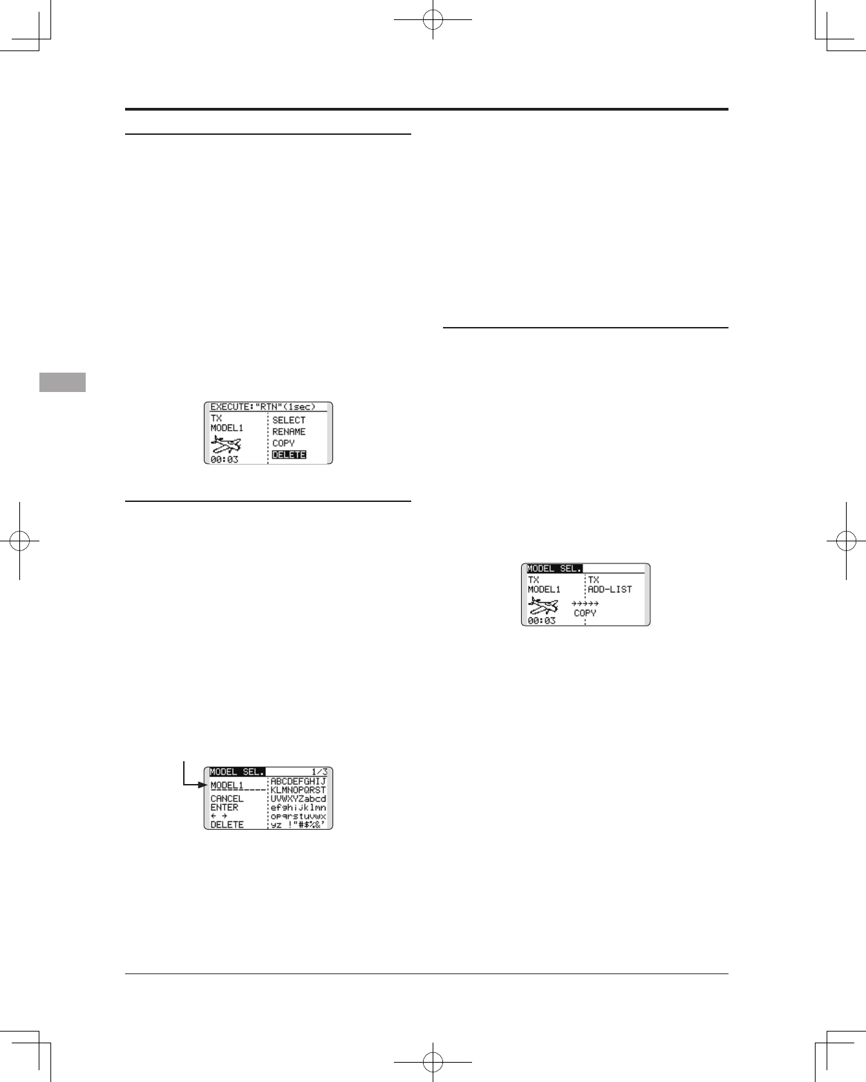
70 <Functions of Linkage Menu>
Model deletion
*The model stored in the transmitter memory or an SD card
can be deleted.
*The current model can not be deleted.
1. Move the cursor to the save destination
display ("TX" or "CARD") and touch the RTN
button to switch to the data input mode.
Select the save destination by scrolling the
touch sensor and touch the RTN button.
[TX]: Transmitter memory
[CARD]: SD card
2. Move the cursor to the model you want to
delete in the model list and then touch the
RTN button.
3. Move the cursor to [DELETE].
4. Touch the RTN button. When a conrmation
message is displayed and the RTN button
is touched for one second, the model is
deleted.
Model name change
*The model name of the model stored in the transmitter
memory or a SD card can be changed.
1. If changing the location:
Move the cursor to the save destination
display ("TX" or "CARD") and touch the RTN
button to switch to the data input mode.
Select the save destination by scrolling the
touch sensor and touch the RTN button.
[TX]: Transmitter memory
[CARD]: SD card
2. Move the cursor to the model you want to
change in the model list and then touch the
RTN button.
3. Move to [RENAME].
4. Touch the RTN button.
*The model name setup screen is displayed.
User name (candidate)
5. Change the model name as described
below:
[Moving cursor in the user name (candidate)]
Select [←] or [→], and touch the RTN button.
[Deleting a character]
When [DELETE] is selected and the RTN button
is touched, the character immediately after
the cursor is deleted.
[Adding a character]
When a character is selected from the
character list and the RTN button is touched,
that character is added at the position
immediately after the cursor.
*A name of up to 10 characters long can be entered as the
model name. (A space is also counted as one character.)
6. After the desired information has been input,
select [ENTER] and touch the RTN button.
(To terminate input and return to the original
state, select [CANCEL] and touch the RTN
button.)
Model copy
*A copy can be made of the model stored in the transmitter
memory or an SD card.
1. If changing the location:
Move the cursor to the save destination
display ("TX" or "CARD") and touch the RTN
button to switch to the data input mode.
Select the save destination by scrolling the
touch sensor and touch the RTN button.
[TX]: Transmitter memory
[CARD]: SD card
2. Select the model you want to copy in the
model list and then touch the RTN button.
3. Move to [COPY].
4. Touch the RTN button.
*The copy screen appears.
5. If replacing the model stored in the
transmitter memory:
Move to [ADD-LIST] and touch the RTN button
to switch to the data input mode.
Select the destination model by scrolling the
touch sensor and touch the RTN button.
[ADD-LIST]: adding the model to the list
[(model name)]: replacing the model
*The model stored in the SD card can be replaced.
If changing the location:
Move the cursor to the copy destination
display ("TX" or "CARD") and touch the RTN
button to switch to the data input mode.
Select the save destination by scrolling the
touch sensor and touch the RTN button.
6. Move to [COPY].
7. Touch the RTN button. When a conrmation
message is displayed and the RTN button is
touched for one second, the model data is
copied.
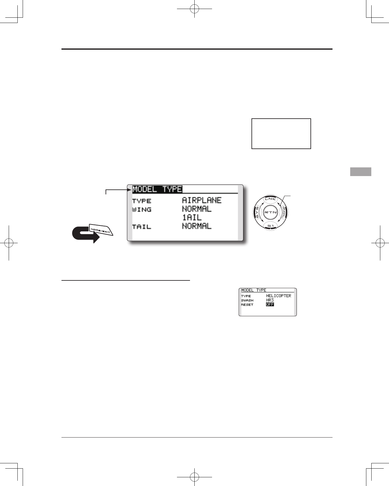
71
<Functions of Linkage Menu>
● Select the function name
and return to the Linkage
menu by touching the
RTN button. Or the
HOME/EXIT button is
pushed.
<SensorTouch™>
RETURN
MODEL TYPE This function selects the model type from among airplane, helicopter,
and glider.
(The display screen is an example. The
screen depends on the model type.)
Six swash types are available for helicopters.
Six types of main wings and three types of tail
wings are available for airplanes and gliders.
Functions and mixing functions necessary for each
model type are set in advance at the factory.
Note: The Model Type function automatically
selects the appropriate output channels,
control functions, and mixing functions for the
chosen model type.
When the Model Type selection command
is accessed, all of the data in the active
memory is cleared (except the following
swash type.) Be sure that you don’t mind
losing this data, or back it up to another
memory using the copying functions.
When changing the helicopter swash type
within the following groups, you can leave
the settings other than the SWASH function.
However, this is initialized when you change
the swash type to the other swash type
group.
Model type selection
1. Move the cursor to the item you want to
change and touch the RTN button to switch
to the data input mode.
Select the desired type by scrolling the
touch sensor and touch the RTN button. A
confirmation message appears. Touch the
RTN button for one second.
Move to [YES] and Touch the RTN button for
one second.
(To terminate input and return to the original
state, touch the S1 button or select [NO] and
touch the RTN button.)
"TYPE": Model type
"WING " (airplane/glider): Wing type
"TAIL" (airplane/glider): Tail type
"SWASH" (helicopter): Swash type
*The wing types which can be selected depend on the mode;
FASST, Multi-ch, or 7ch, etc.
● Select [MODEL TYPE] in the Linkage menu and
access the setup screen shown below by touching
the RTN button.
2. If resetting the data when changing the
helicopter swash type:
(Helicopter)
Move the cursor to [OFF] and touch the RTN
button to switch to the data input mode.
Select [ON] by scrolling the touch sensor
and touch the RTN button. A confirmation
message appears. Touch the RTN button.
Activate the swash type setting. The swash
setting parameters are reset.
Swash type group A:
H-1, H-3, HR3, and HE3
Swash type group B:
H-4, H-4X
Scrolling
● Moving cursor
● Selecting mode
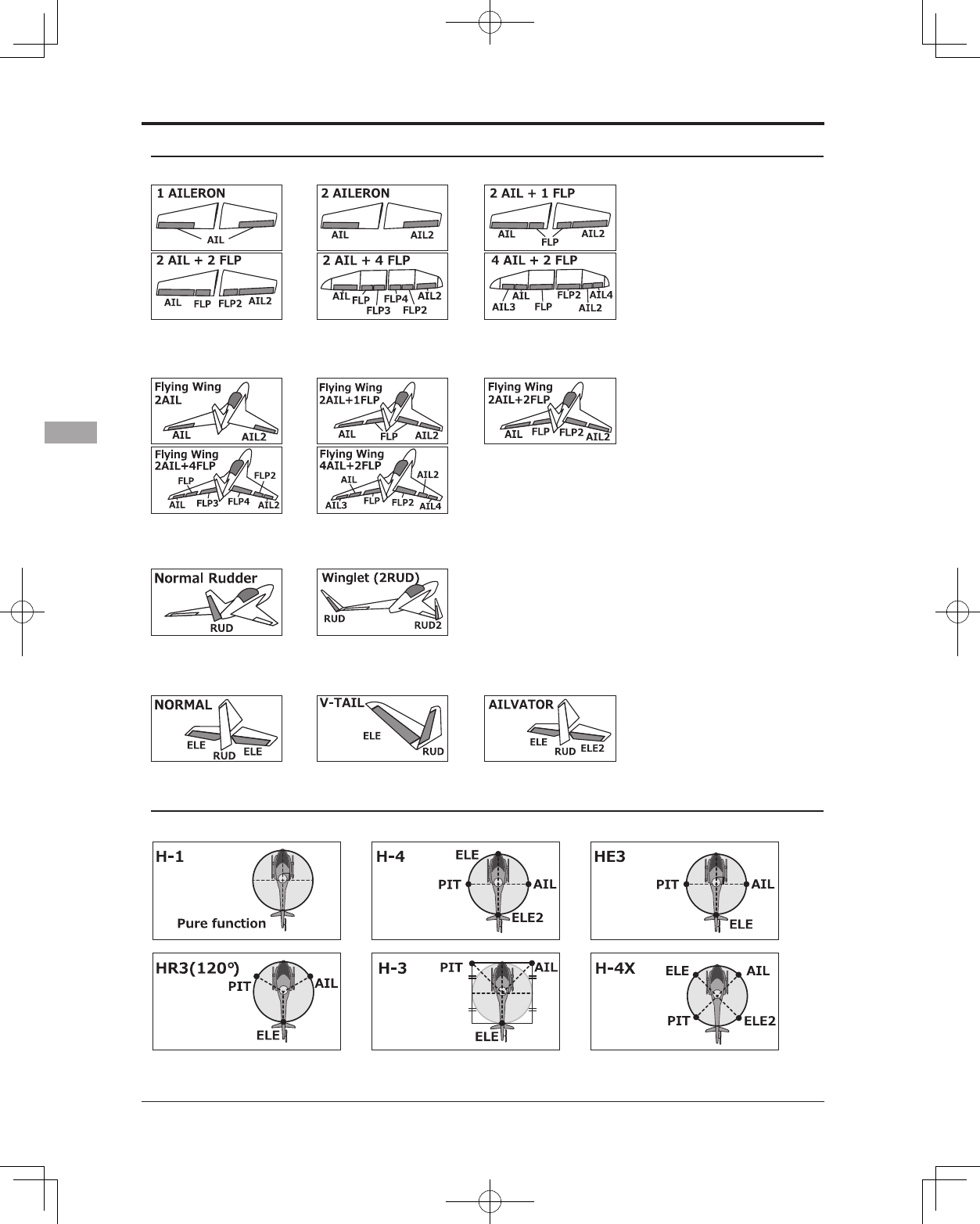
72 <Functions of Linkage Menu>
Model type selection (Airplane, Glider)
●Wing type (Normal)
●Wing type (Tailless wing)
●Rudder type
●Tail type
Model type selection (Helicopter)
●Swash type
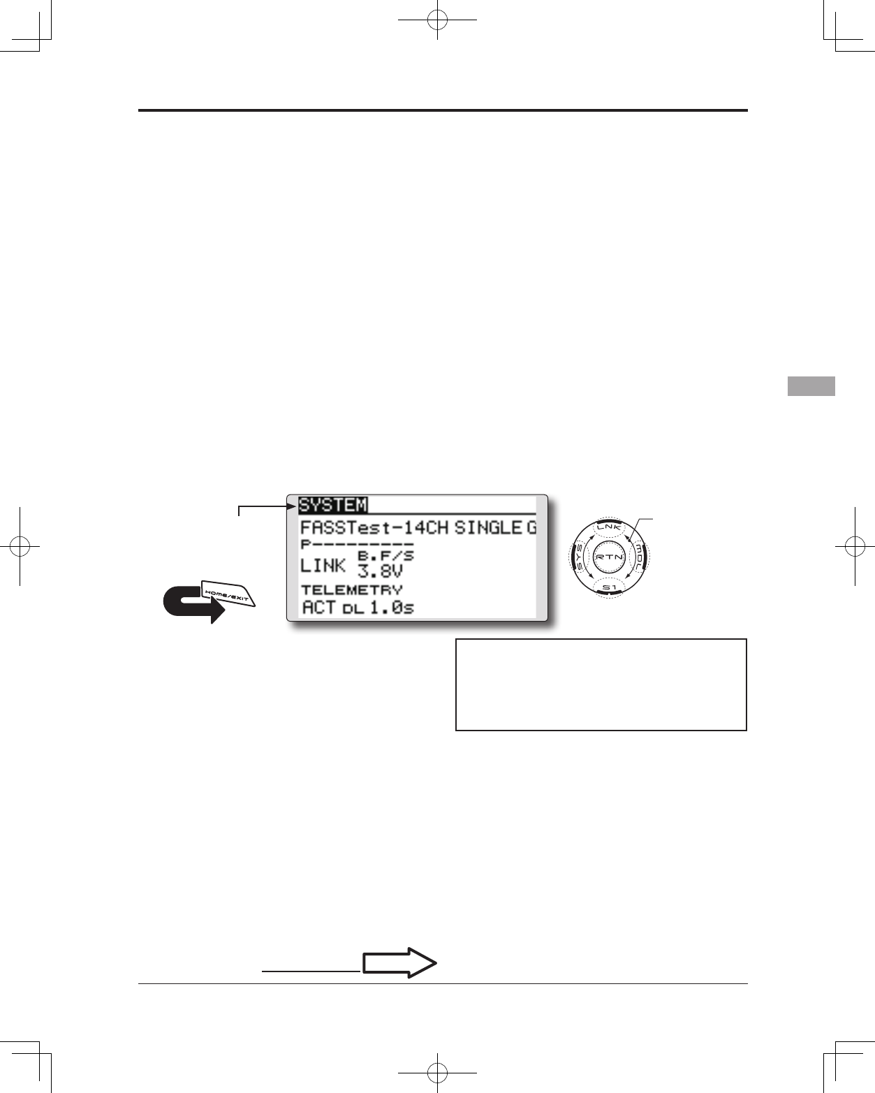
73
<Functions of Linkage Menu>
● Select the function name
and return to the Linkage
menu by touching the
RTN button. Or the
HOME/EXIT button is
pushed.
<SensorTouch™>
RETURN
System Type selection
The T14SG is for 2.4GHz only. The system
can be changed from among 5 choices: FASSTest
14CH, FASSTest 12CH, FASST MULTI,
FASST 7CH, S-FHSS. It is FASSTest14CH and
FASSTest12CH which can be chosen by R7008SB
set. The method of selection is to the next page.
*If you change the System Type, other model data is not
reset.
*If a system type is changed in Helicopter mode, the
transmitter will offer two selections:
[Yes] : Selection sets the channel order suitable for System
Type. (We recommend here. )
[No] : The present channel order is maintained.
*After any change, remember to test the model and should
fully check servo direction and a motion.
*Analog servos cannot be used with the R7008SB in the
SYSTEM System mode setting, Receiver link
Area mode selection (Frequency range)
The T14SG transmitter has been designed to
function in many countries. If you will be utilizing
this transmitter in a country other than France,
please make sure that [AREA] is set to "G". If,
however, this transmitter will be utilized in France,
it must be set to "F" in order to comply with French
regulations.FASST mode selection
Receiver linking
The receiver will only be controlled (without
being affected by other transmitters) by the
transmitter it is linked to. When using a receiver
other than one purchased as a set, linking is
necessary.
Moreover, a re-link is required when a new
model is added by model selection, and the time of
system type change.
FASSTest 12CH mode.
Dual receiver function (only FASSTest 14CH
mode)
Dual receivers can be linked with the T14SG.
Two receivers are recognized individually by ID
numbers. For example, in R7008SB, CH output
setting function is used, by setting the first as as
"1-8CH", and setting the second as "9-14CH", two
sets of receivers can be used as a set in the model,
allowing you 14 channels. If a Dual receiver
function is used, the following function can set up
individually.
・Battery fail-safe voltage setup
・Telemetry function ON/OFF
・Sensor setup
Battery fail-safe voltage setup (only FASSTest
mode)
The voltage which battery fail-safe activates,
can be set when you link. (3.5-8.4V) The receiver
memorizes the setting as it was at link.
Suggested setting voltages are as follows.
• 4 cells NiCd or NiMH (Normal: 4.8v) = 3.8 v
• 2 cells LiFe (Normal: 6.6 v) = 6.0 ~ 6.2 v
• 2 cells LiPo (Normal: 7.4 v) = 7.2 ~ 7.4 v
It is a rough reference value.
Since it changes with servos carried in the
condition and the model of a battery, please set to
your own model in a battery consumption current.
● Select [SYSTEM] in the Linkage menu and access
the setup screen shown below by touching the
RTN button.
Scrolling
● Moving cursor
● Selecting mode
P.37
Linking method
Cases when linking is necessary:
・When using a receiver other than the initial setting.
・When the communication system was changed.
(FASSTest14CH ↔FASSTest12CH etc. )
・When a new model was created by model
selection.
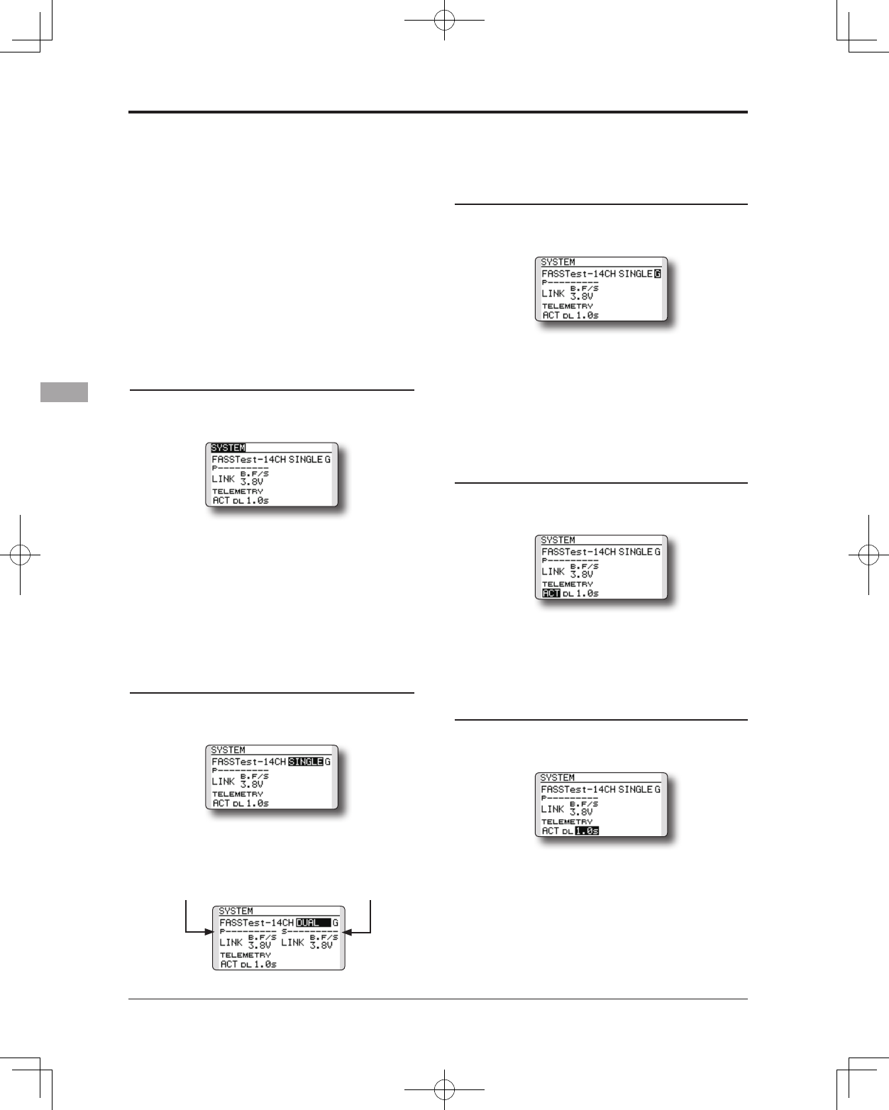
74 <Functions of Linkage Menu>
Telemetry function (FASSTest mode only)
To use the telemetry function, set “Telemetry”
to “ACT”.
DL Interval (FASSTest mode only)
When a telemetry function is enabled, the
receiving interval (down-link interval) of sensor
data can be changed.
If a DL interval is increased, the response of
the sensor data display becomes slower, but stick
response will improve.
System Type selection procedure
1. Move the cursor to the [FASSTest-14CH]
item and touch the RTN button to switch to
the data input mode.
2. Select the system type by scrolling the
touch sensor.
[FASSTest-14CH][FASSTest-12CH][FASST-
MULT][FASST-7CH][S-FHSS]
*An example of selections for each system is on the
following page.
3. Touch the RTN button to end adjustment
and return to the cursor mode.
Dual receiver function (only FASSTest 14CH
mode) procedure
1. Move the cursor to the [SINGLE] item and
touch the RTN button to switch to the data
input mode.
2. Select the [SINGLE] or [DUAL] by scrolling
the touch sensor.
3. Touch the RTN button to end adjustment and
return to the cursor mode.
Area mode selection (Frequency range)
procedure
1. Move the cursor to the [G] item and touch
the RTN button to switch to the data input
mode.
2. Select the [G]or[F] by scrolling the touch
sensor.
*"F" is chosen only when using the transmitter is used in
France. Leave this in "G" otherwise.
3. Touch the RTN button to end adjustment and
return to the cursor mode.
Telemetry ACT/INH procedure
1. Move the cursor to the TELEMETRY [ACT] item
and touch the RTN button to switch to the
data input mode.
2. Select the [ACT]or[INH] by scrolling the touch
sensor.
3. Touch the RTN button to end adjustment and
return to the cursor mode.
DL Interval set procedure
1. Move the cursor to the TELEMETRY DL[1.0s]
item and touch the RTN button to switch to
the data input mode.
2. Select the DL time by scrolling the touch
sensor. If a DL interval is increased, the
response of the sensor data display becomes
slower, but stick response will improve.
Initial value: 1.0s
Adjustment range : 0.1s~2.0s
3. Touch the RTN button to end adjustment and
return to the cursor mode.
ID of a Primary
receiver displays.
ID of a Secondary
receiver displays.
In DUAL, a primary receiver is link previously.
Next, a secondary receiver is link.
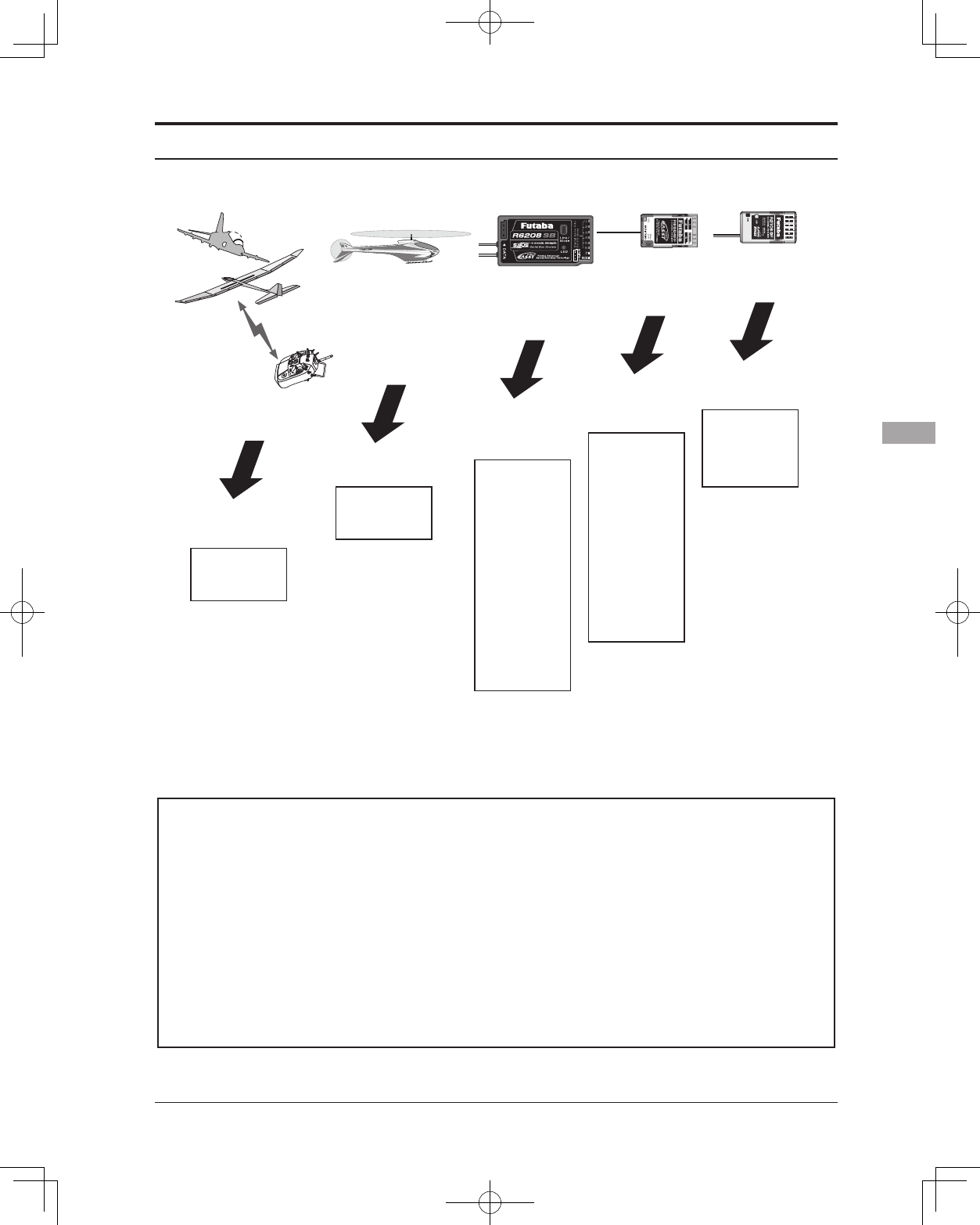
75
<Functions of Linkage Menu>
System Type
■FASSTest 14CH ---
■FASSTest 12CH ---
■FASST MULTI ---
■FASST 7CH ---FASST-7CHsystemreceivermode.Upto7channelscanbeused.
■S-FHSS ---S-FHSSsystemreceivermode.Upto8channelscanbeused.
FASSTestsystemreceivermode.Applicablewiththetelemetrysensorunit.Upto
18channels(linear12+ON/OFF2)canbeused.
FASSTestsystemreceivermode.Applicablewithreceivervoltagedisplay.Upto12
channels(linear10+ON/OFF2)canbeused.TelemetrySensorcannotbeused,but
theresponsespeedisafasterthanthatofthe14CHmode.
FASST-MULTIsystemreceivermode.Upto14channels(linear12+ON/OFF2)can
beused.
•AnalogservoscannotbeusedwiththeR7008SBintheFASSTest12CHmode.
-Response speed has
priority over number
of channels
-Telemetry requires
only the current
receiver battery
-Want to use a
previously used
receiver as is
-Want to use a
miniature receiver
for indoor planes
-Want to use an
S-FHSS system
miniature receiver
FASSTest 14CH
FASSTest 12CH
FASST MULTI
FASST 7CH S-FHSS
R608FS
R6008HS
R6108SB
R6208SB
R6014HS
R6014FS
R6203SB
R6203SBE
R6202SBW
R6303SB
R6303SBE
R7008SB
R7003SB
R617FS
R6004FF
R616FFM
R6106HF
R6106HFC
R6203SB
R6203SBE
R6202SBW
R6303SB
R6303SBE
R2006GS
R2106GF
R2008SB
R7008SB
R7003SB
(Usable receivers)
-Want to use more channels
-Want to use a large number
of telemetry functions
(The time of December, 2012)
The example for choosing System Type
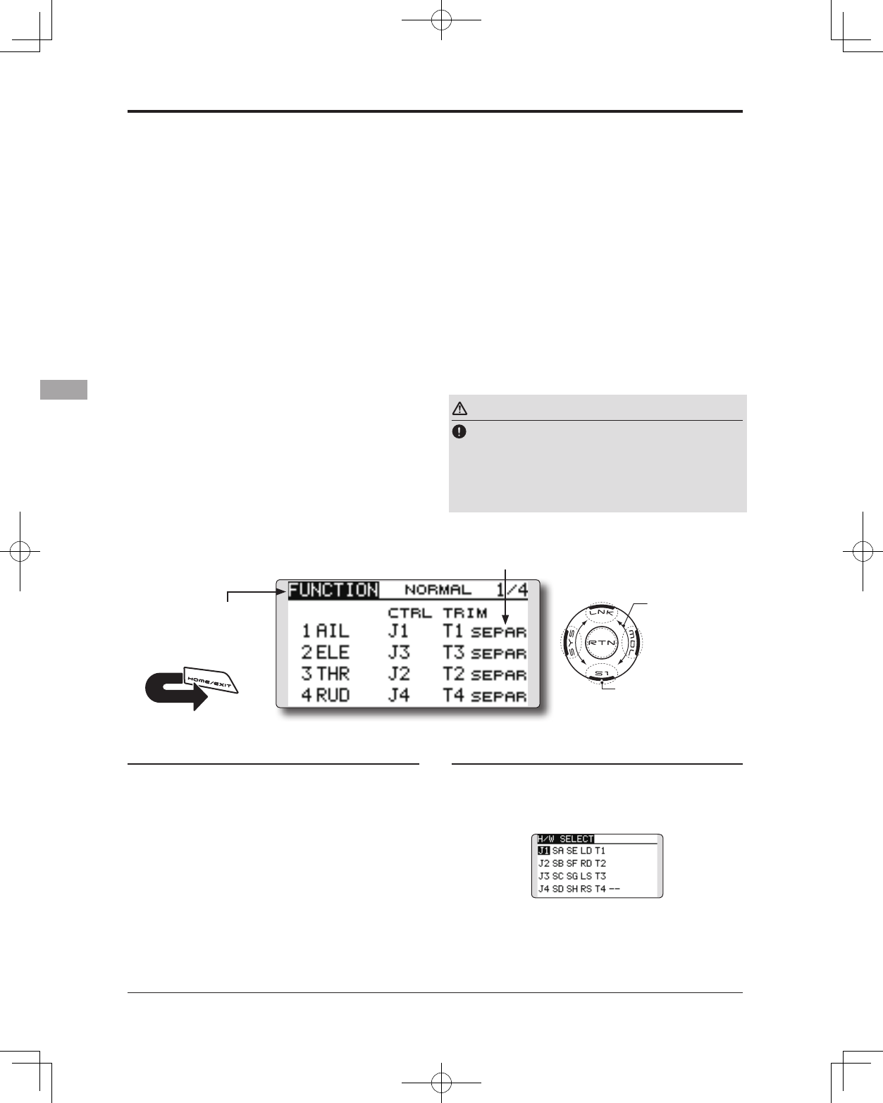
76 <Functions of Linkage Menu>
● Select the function name
and return to the Linkage
menu by touching the
RTN button. Or the
HOME/EXIT button is
pushed.
<SensorTouch™>
RETURN
FUNCTION Channel assignment of each function can be changed.
When you select model and wing (swash) types,
you will find that the optimized combinations of
servo output channels and functions have been
already preset. If you would like, you can freely
change combinations of servo output channels,
functions (aileron, elevator, etc), and control (sticks,
switches, and trim levers).
*You can also assign the same function to multiple servo
output channels such as assigning elevator function to CH2
and CH3.
Channel Replacement
When the channel is replaced in the Function
menu, replaced channel uses the setting data (ATV,
SUB-TRIM, REVERSE, F/S, and B-F/S, etc.).
Servo Output Channels
For FASSTest 14CH mode, you can set 12 linear
channels and two digital channels. For FASSTest
12CH mode, you can set 10 linear channels and
two digital channels. For FASST MULT mode, you
can set 12 linear channels and two digital channels.
Function change
1. Move the cursor to the function item of the
channel you want to change and touch the
RTN button.
*The function selection screen is displayed.
2. Move the cursor to the function name you
want to set and touch the RTN button.
*The function name blinks.
3. Touch the RTN button to execute the
change. (When you want to cancel this
operation, touch the S1 button.)
*Multiple channels can be assigned to one function.
For FASST 7CH mode, you can set only 7 linear
channels. For S-FHSS mode, you can set only 8
linear channels.
*DG1/2 (digital channels)
These channels can function as switched channels. You can
freely change combinations between servo output channels
and input controls (sticks, switches, and trim levers).
Motor Function
If you have either a Glider or Airplane Model
Type selected, and choose to activate the Motor
function, a reverse setting screen is displayed.
*If YES is selected, the output is reversed. If NO is selected,
the output is normal.
Warning
As a safety precaution to prevent the motor
from starting unexpectedly, please switch
off the motor accordingly. We also suggest
removing the propeller from the motor as an
additional precaution.
Operation control change
1. Move the cursor to the "CTRL" item of the
channel you want to change and touch the
RTN button.
*The control selection screen is displayed.
2. Move the cursor to the control you want to
change, and touch the RTN button.
*The same control can be assigned to multiple channels.
(The display screen is an example. The
screen depends on the model type.)
● Select [FUNCTION] in the Linkage menu and
access the setup screen shown below by touching
the RTN button.
● Trim operation mode
"COMB": Combination mode
"SEPAR": Separate mode
It sets up by T1-T4 SET of LINKAGE MENU.
Scrolling
● Moving cursor
● Selecting mode
● Adjusting value
● To next page
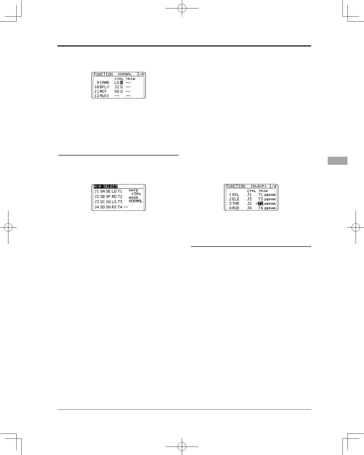
77
<Functions of Linkage Menu>
Camber/Motor/Buttery control setting (glider)
*Camber/Motor/Buttery function control can be changed for
each condition.
Camber, Motor or Butterfly control group/
single setting is performed at the function
setup screen.
"G": Group (common to all conditions)
"S": Single (set for each condition)
Trim setting
Move the cursor to the "TRIM" item of the
channel you want to change and touch the
RTN button.
*The trim setup screen is displayed.
The following items can be set at the trim
setup screen:
Trim selection
Move the cursor to the trim, lever, etc. you
want to set and touch the RTN button.
*The setting can be changed.
Trim rate setting
Move the cursor to the [RATE] item and
touch the RTN button to switch to the data
input mode.
Set the trim rate by scrolling the touch sensor.
Initial value: +30%
Adjustment range : -150~+150%
(When the RTN button is touched for one second, the trim
rate is reset to the initial value.)
Touch the RTN button to end adjustment and
return to the cursor mode.
Trim mode selection
Move the cursor to the [MODE] item and
touch the RTN button to switch to the data
input mode.
Select the trim mode by scrolling the touch
sensor. A confirmation message appears.
Touch the RTN button to change the mode.
(To terminate input and return to the original
state, touch the S1 button.)
[NORM]: Normal mode. Normal trim (parallel
shift trim) operation.
[ATL]: ATL operation mode. Maximum
change near idle or low-stick position,
normally used with throttle trim. It is also
possible to reverse the travel.
*[NORMAL]/[REVERSE] selection is possible in "ATL"
mode.
Throttle trim (helicopter only)
* The throttle trim in conditions other than "Normal"
condition can be inhibited.
When other than normal condition is
selected, move the cursor to throttle trim on
the function setup screen and touch the RTN
button for 1 second.
*When "X" is displayed, THR trim is inhibited in conditions
other than normal condition.
Channel replacement
Move the cursor to the channel # you want
to replace and touch the RTN button to
switch to the data input mode.
Select the destination channel # by scrolling
the touch sensor. A confirmation message
appears. Touch the RTN button to replace
the channel. (To terminate input and return
to the original state, touch the S1 button.)
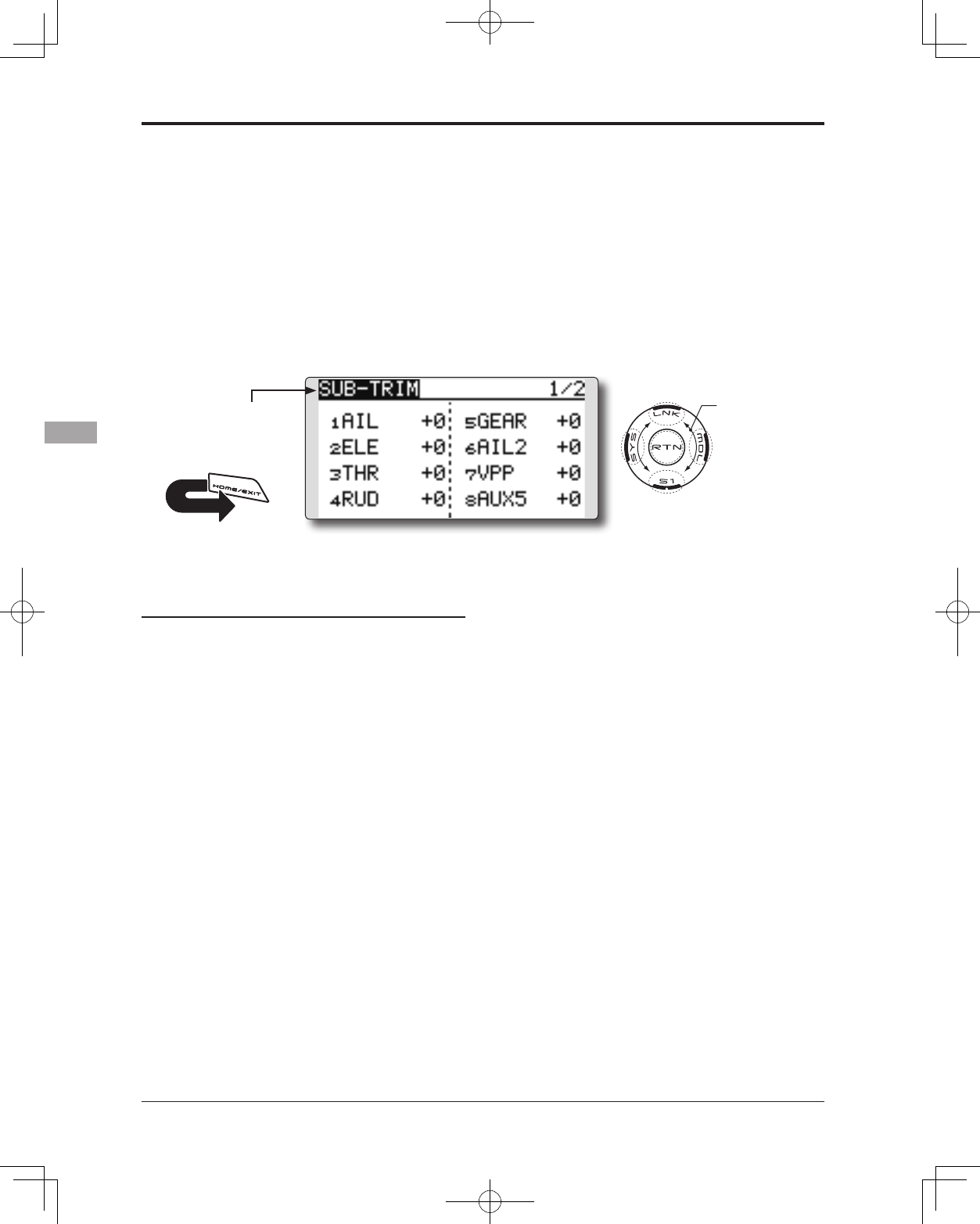
78 <Functions of Linkage Menu>
● Select the function name
and return to the Linkage
menu by touching the
RTN button. Or the
HOME/EXIT button is
pushed.
<SensorTouch™>
RETURN
SUB-TRIM Setting of neutral position of each servo.
(The display screen is an example. The
screen depends on the model type.)
The Sub-Trim function is used to set the servo
neutral position, and may be used to make fine
adjustments to the control surface after linkages
and pushrods are hooked up. When you begin to set
up a model, be sure that the digital trims are set to
their center position.
Sub-trim adjustment
1. Move the cursor to the channel you want to
adjust and touch the RTN button to switch to
the data input mode.
2. Adjust the rate by scrolling the touch sensor.
Initial value: 0
Adjustment range: -240~+240 (steps)
(When the RTN button is touched for one second, sub-trim is
reset to the initial value.)
*Before sub-trim adjustment, it is very important to adjust the
linkages at the control surface so that you do not use sub-
trim, except for very minute adjustments.
3. Touch the RTN button to end adjustment and
return to the cursor mode.
4. Repeat this procedure for each channel.
● Select [SUB-TRIM] in the Linkage menu and access
the setup screen shown below by touching the
RTN button.
Scrolling
● Moving cursor
● Adjusting value
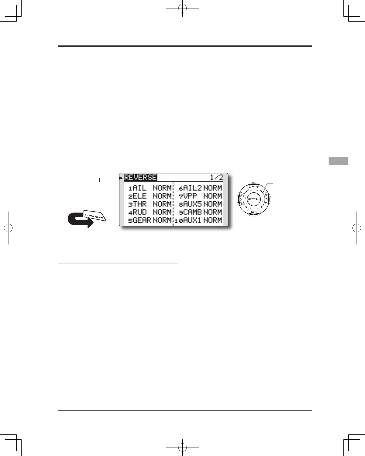
79
<Functions of Linkage Menu>
● Select the function name
and return to the Linkage
menu by touching the
RTN button. Or the
HOME/EXIT button is
pushed.
<SensorTouch™>
RETURN
REVERSE Use to reverse the throw direction.
Servo Reverse changes the direction of an
individual servo’s response to a control input.
For CCPM helicopters, be sure to read the
section on Swash AFR before reversing any servos.
With CCPM helicopters, always complete your
servo reversing prior to any other programming.
If you use pre-built Airplane/Sailplane functions
that control multiple servos, it may be confusing
Servo reversing procedure
*Upon setup completion of a new model, check whether or
not each servo is connected to the correct channel.
*Next, determine whether you need to reverse any channels
by moving each stick and/or other control inputs.
1. Move the cursor to the channel you want to
reverse and touch the RTN button to switch
to the data input mode.
2. Select the direction by scrolling the touch
sensor. A conrmation message appears.
[NORM]: Normal
[REV]: Reverse
3. Touch the RTN button to change the
direction. (To terminate input and return to
the original state, touch the S1 button.)
*Repeat the operation above for each channel that must be
reversed.
to tell whether the servo needs to be reversed or a
setting in the function needs to be reversed. See the
instructions for each specialized function for further
details. Always check servo direction prior to every
ight as an additional precaution to conrm proper
model memory, hook ups, and radio function.
(The display screen is an example. The
screen depends on the model type.)
● Select [REVERSE] in the Linkage menu and access
the setup screen shown below by touching the
RTN button.
Scrolling
● Moving cursor
● Selecting mode
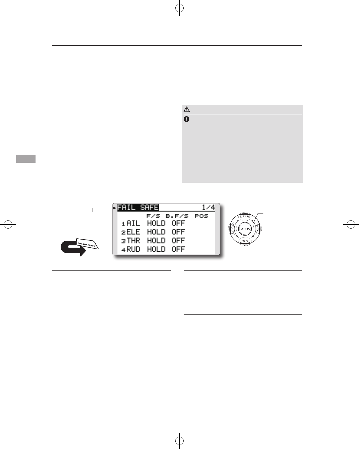
80 <Functions of Linkage Menu>
● Select the function name
and return to the Linkage
menu by touching the
RTN button. Or the
HOME/EXIT button is
pushed.
<SensorTouch™>
RETURN
FAIL SAFE Sets the servos operating position when transmitter signals can no
longer be received or when the receiver battery voltage drops.
(The display screen is an example. The
screen depends on the model type.)
The Failsafe function may be used to set up
positions that the servos move to in the case of
radio interference.
You may set either of two positions for each
channel: Hold, where the servo maintains its last
commanded position, or Failsafe, where each
servo moves to a predetermined position. You may
choose either mode for each channel. (FASST 7CH
mode: CH3 only)
The T14SG system also provides you with an
advanced battery monitoring function that warns
you when the receiver battery has only a little
power remaining. In this case, each servo is moved
to the defined failsafe position. (FASST 7CH
mode: CH3 only) The battery failsafe may be
released by operating a predefined control on the
transmitter (default is throttle), do not continue
to fly, land as soon as possible. Remember, if the
Fail safe setting procedure
1. Move the cursor to the "F/S" item of the
channel you want to set and touch the RTN
button to switch to the data input mode.
2. Select the F/S mode by scrolling the touch
sensor. A conrmation message appears.
*The display blinks.
3. Touch the RTN button. (Touch the S1 button
to stop setting.)
*The channel switches to the F/S mode.
4. Move the cursor to the "POS" item.
Hold the corresponding stick, knob, slider,
etc. in the position you want the servo
to move to when the fail safe function is
activated and Touch the RTN button for one
second.
*The set position is displayed in percentage.
*If you want to return that channel to the hold mode, move
the cursor to the "F/S" item and touch the RTN button
to switch to the data input mode. Select the F/S mode by
scrolling the touch sensor. A conrmation message appears
and then change the mode by touching the RTN button.
predefined control suddenly moves to a position
you did not command, land at once and check your
receiver battery.
Denes servo position when signals are lost and
when receiver battery voltage becomes low.
Warning
For safety, always set the fail safe functions.
●Remember to set the throttle channel fail safe function so that
the servo moves to the maximum slow side for airplanes and
to the slow side from the hovering position for helicopters.
Crashing of the model at full high when normal radio waves
cannot be received due to interference, etc., is very dangerous.
●If the battery fail safe is reset by the throttle stick, it may
be mistaken for an engine malfunction and will be reset at
throttle slow and the model will continue to y. If you have
any doubts, immediately land.
Battery fail safe setting procedure
Battery fail safe can be set for each channel
by the same method as the fail safe setting
procedure. Select and set the "B.F/S" item.
[ON]: Battery fail safe function ON
[OFF]: Battery fail safe function OFF
Battery fail safe release switch setting
This function temporarily releases the battery
fail safe function, so the fuselage can
recover after the battery fail safe function
was activated by a drop in the receiver
battery voltage. This setting selects the switch
which releases the battery fail safe function.
1. Move the cursor to the [RELEASE B.F/S] item in
the setup screen (last page).
2. Touch the RTN button.
*The switch selection screen is called.
*For a detailed description of the switch selection and ON/
OFF direction setting method, see [Switch Setting Method]
at the back of this manual.
● Select [FAIL SAFE] in the Linkage menu and access
the setup screen shown below by touching the
RTN button.
Scrolling
● Moving cursor
● Selecting mode
● Adjusting value
● To next page