Futaba T14SG-24G Radio Control User Manual 2
Futaba Corporation Radio Control 2
UserManual.wiki
>
Futaba
>
T14SG-24G User Manual
>
User Manual 2
Contents
1.
User Manual 1
2.
User Manual 2
3.
User Manual 3
User Manual 2
Navigation menu
Upload a User Manual
Namespaces
Wiki Guide
HTML
PDF
Info
Views
User Manual
Discussion / Help
Navigation
![33<Basic Operation>BASIC OPERATIONHow to charge the NiMH battery HT5F1800B for the transmitterDangerThe NiMH battery HT5F1800B is only for your T14SG. Do not use this battery for other equipment.Be sure to use the attached special charger to charge the battery.*If you take the NiMH battery HT5F1800B out of the transmitter, you can use the optional quick charger CR-2000 corresponding to NiMH battery.[Method of charging battery]*Connect to AC outlet specified.●Special chargerReceiver Batt.Charging displayTo T14SG charge connectorTransmitter Batt.Charging display1. Connect the special charger to the wall socket (AC outlet).2. Connect the connectors to the T14SG charging jack.*Conrm that the charging indicator, LED lamp, is on.*Turn off the transmitter while charging the battery.3. Remove the battery after 15 hours.*Battery charging will not automatically stop. Remove the battery and transmitter from the charger and remove the charger from the wall socket.*It is recommended to reactivate the battery by cycling several times if the battery has not been used for a long period. *In the case of NiMH/NiCd batteries, you may find poor performance of the battery if you have used the battery only for a short period or if you repeat charging while the battery is not fully discharged. It is suggested to discharge the battery to the recommended level after use. It is also recommended to charge the battery just before use. Battery ChargingBefore charging batteries, read the "Cautions for handling battery and battery charger" in the section "NiMH/NiCd Battery Safety and Handling Instructions".](https://usermanual.wiki/Futaba/T14SG-24G.User-Manual-2/User-Guide-1894989-Page-3.png)
![34 <Basic Operation>How to turn transmitter power ON/OFF When turning on the power, the T14SG transmitter will begin emmiting RF automatically after it conrms the surrounding RF conditions. The T14SG transmitter also offers the ability to auto shut-down.When turning on the power of the transmitter1. Turn on the power switch of the transmitter.*The message "CHECK RF CONDITION" is displayed for a moment. At the same time the left LED monitor blinks.2. Then, you will see the home screen and the transmitter begins to emit radio waves.*The left and right LED monitors will change to solid red.How to stop the transmitter1. Turn off the power switch of the transmitter.*The transmitter shuts down at once.Low battery alarm and auto shut-downWhen the battery voltage reaches 5.2V, an audible alarm will sound. Land your aircraft immediately.When the battery voltage reaches 3.9V, the transmitter will be turned off automatically.*If you do not operate the transmitter (or move a stick, knob, switch or digital trim) for 30 minutes, the message "PLEASE TURN OFF POWER SWITCH" is displayed and an audible alarm will sound.Warning display at power ON (Airplane/Helicopter) When the throttle stick during Power On is at the high side (or over 1/3 stick) a warning will be displayed. *below 1/3 stick, the warning display goes off.Registration of the user's nameIf so desired, the T14SG transmitter can indicate the owner's name. User's name setup screen1. Turn on the power of the transmitter.*The home screen appears.2. Lightly touch the SYS button twice rapidly and the System menu appears.3. Select [USER NAME] in the System menu and touch the RTN button.*The user name set up screen appears. Input Box*Current user name is displayed. Changing the user name1. Change the user name as described below: [Moving cursor in input box] Select[←]or[→],andtouchtheRTNbutton. [Deleting a character] When [DELETE] is selected and the RTN button is touched, the character immediately after the cursor is deleted. [Adding a character] When a character is selected from the character list and the RTN button is touched, that character is added at the position immediately after the cursor.*A name of up to 10 characters long can be entered as the user name. (A space is also counted as one character.)2. At the end of input, select [ENTER] and tuoch the RTN button. (To terminate input and return to the original state, select [CANCEL] and touch the RTN button.)THR Stick Slow](https://usermanual.wiki/Futaba/T14SG-24G.User-Manual-2/User-Guide-1894989-Page-4.png)
![35<Basic Operation>Up/Down timer (ST1, ST2)•Timerisdisplayedhere. Touch the RTN button at the [xx]:[xx.xx] item to start/stop the timer. • Usethecursortohighlightthis,thentouch the RTN button at the ST1 or ST2 item to call the timer set-up screen. *See the description at the back of this manual.Home screenDigital trim (T1 to T4)• Trimpositionisdisplayedhere.• Youcanselectthedisplayuniton the home screen on the T1-T4 setting screen within the linkage menu.Model Name•Themodelnamethatis currently used is displayed here. •Usethecursortohighlight this, then touch the RTN button to call the model select set-up screen.User's nameSystem timer•Thisshowstheaccumulatedtimesincethe latest reset. (Hour):(Minute)•Usethecursortohighlightthis,thentouch the RTN button for one second to reset the system timer.Use the touch sensor to select the following display area to call each setting screen, and touch the RTN button. The setting screen appears.RF indicatorBattery Indicator• Whenthebatteryvoltagereaches 5.2V(Change in Warning Menu), the alarm will beep. Land your aircraft immediately.System mode•System(FASSTest14CHetc.)mode is displayed here.•Usethecursortohighlightthis,then touch the RTN button to call the frequency set-up screen.2nd Home screen•TouchtheRTNbuttonatthe clock icon to call the 2nd home screen (large size timer). Model timer•Thisshowstheaccumulated timesince the latest reset. (each model) (Hour):(Minute)•Usethecursortohighlightthis,then touch the RTN button for one second to reset the model timer.Key lock• TouchtheS1 buttonorpush theHOME/EXIT button for one second to lock/unlock the key operation. In the key lock mode the key icon is displayed here.Model typeSD card indicatorCondition name (Heli/Glider)•Inthenormalcondition,movethecursor to the condition name and touch the RTN button. The condition name is changed and blinks. It is possible to operate the digital trim in all conditions.VPP condition # (Air)•WhenVPPfunctionisassignedtoachannel,thecurrentVPPcondition# is displayed here.](https://usermanual.wiki/Futaba/T14SG-24G.User-Manual-2/User-Guide-1894989-Page-5.png)

![37<Basic Operation> Link procedure (T14SG/R7008SB)Each transmitter has an individually assigned, unique ID code. In order to start operation, the receiver must be linked with the ID code of the transmitter with which it is being paired. Once the link is made, the ID code is stored in the receiver and no further linking is necessary unless the receiver is to be used with another transmitter. When you purchase additional R7008SB receivers, this procedure is necessary; otherwise the receiver will not work. Link procedure1.Placethetransmitterandthereceivercloseto each other within half (0.5m) meter. 2. Turn on the transmitter. 3. Select [SYSTEM] at the Linkage menu and access the setup screen shown below by touching the RTN button.4. When you use two receivers on one model, you must change from [SINGLE] to [DUAL]. *Only two receivers can be used. In "DUAL", two setting items come out. Input, respectively.5."F"willbechosenifitisusedinFrance.others"G" general.6. When changing battery fail-safe voltage from the initial value 3.8V, voltage is changed here. *OnlyinFASSTestMode.7.[LINK] is chosen by scrolling and the RTN button is pushed. The transmitter will emit a chime as it starts the linking process.8. When the transmitter starts to chime, power on the receiver. The receiver should link to the transmitter within about 1 second. 9. If linking fails, an error message is displayed. Bring the transmitter closer to the receiver and repeat the procedure above from Step 2.10. ACT will be chosen if telemetry is used. It is INH when not using it. Less than 0.5 mIn "Link" ModeReceiver ON:You can do this through the LINKAGE Menu and scroll to System and press RTN.IDofaPrimaryreceiver displays.In DUAL, a primary receiver is link previously. Next, a secondary receiver is link.ID of a Secondary receiver displays.](https://usermanual.wiki/Futaba/T14SG-24G.User-Manual-2/User-Guide-1894989-Page-7.png)
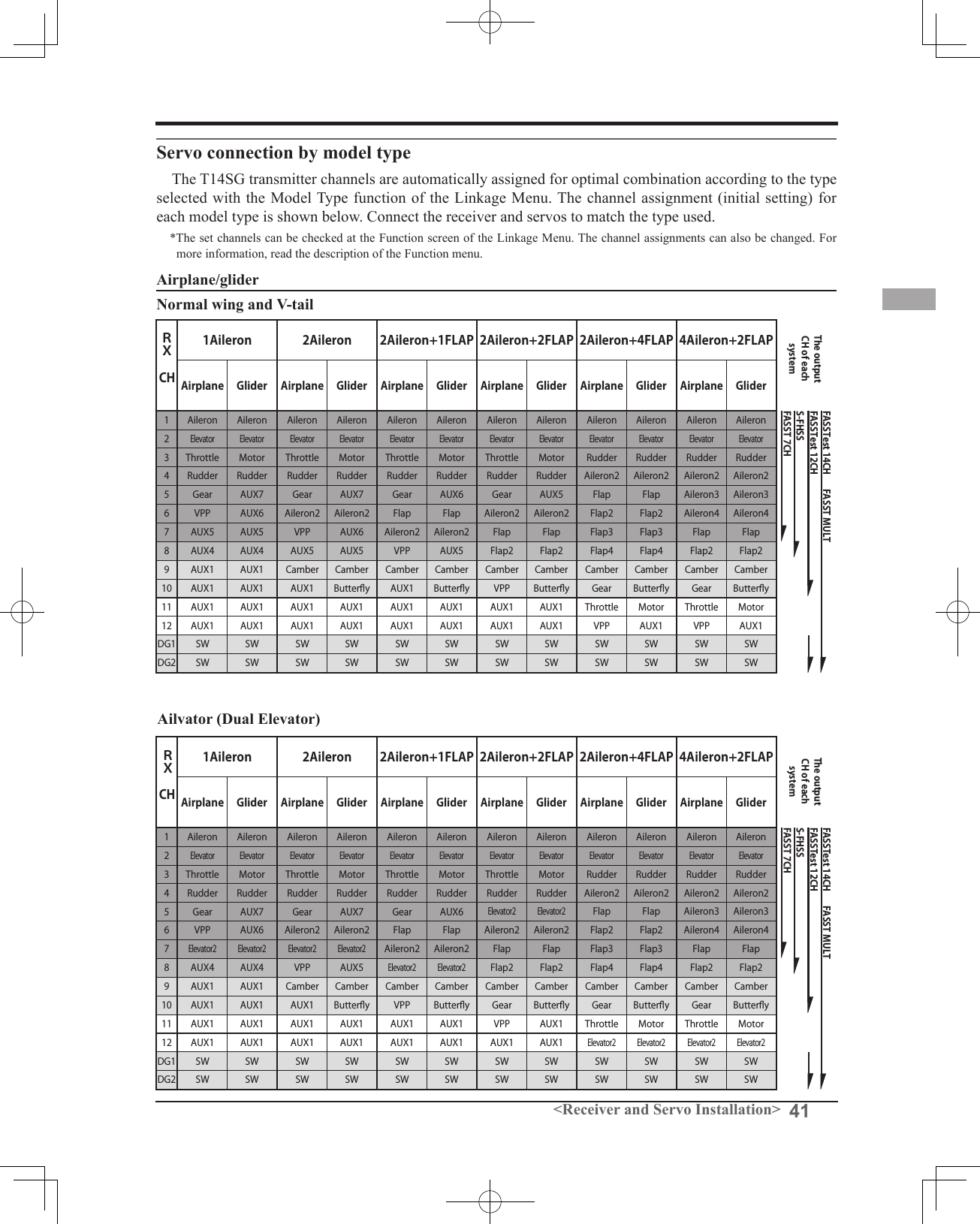
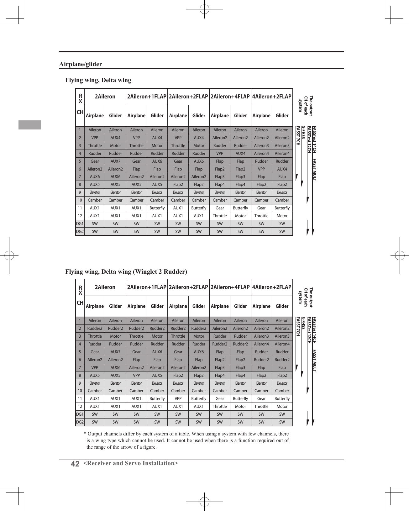
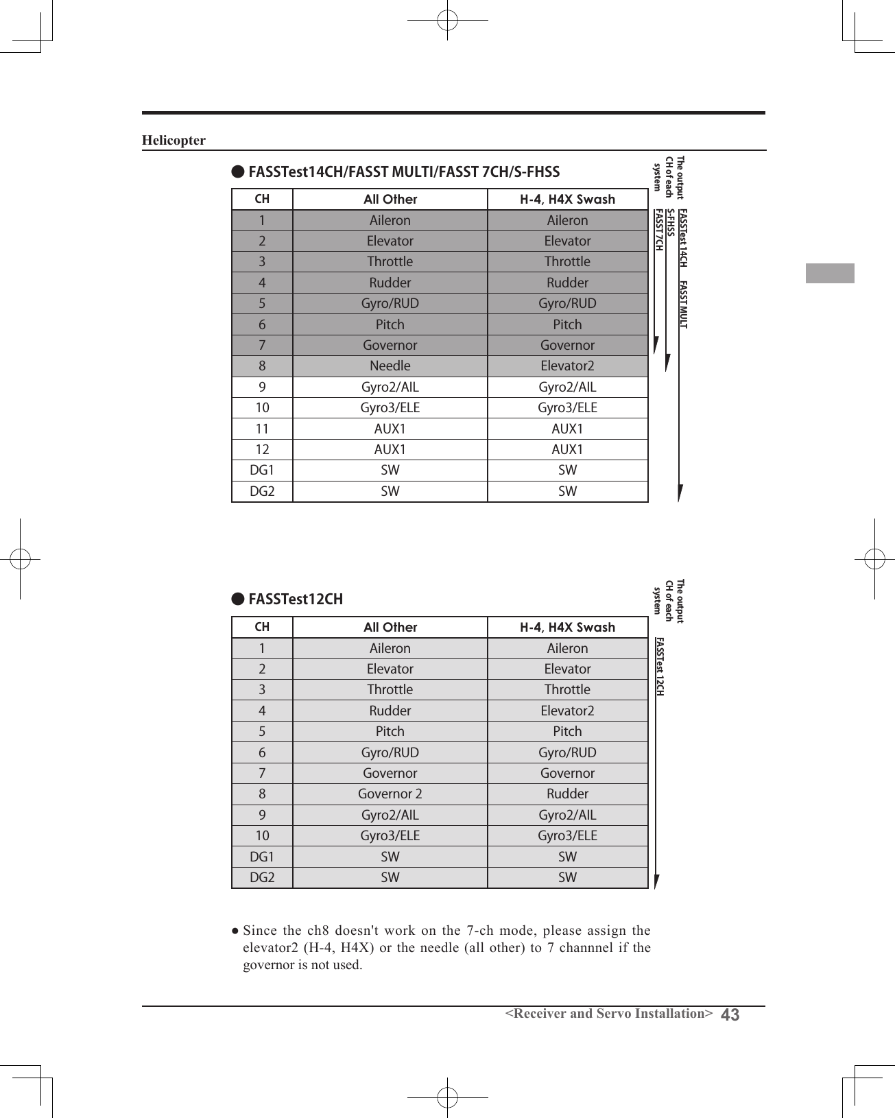
![40 <Receiver and Servo Installation>RECEIVER AND SERVO INSTALLATIONReceiver switchReceiver batteryCharging portServosR7008SB (output connector section)•CH1~6: Output connectors 1~6•7/B: Output connectors 7 and Power supply•8/SB: Output connectors 8 or S.BUS system•S.BUS2: S.BUS2 systemCH1~8, S.BUS/(2), BReceiver and servos connection diagramAlways connect the necessary number of servos.The receiver channel assignment depends on the model type. See the Servo connection by model type tables.Receiver and servos connectionConnect the receiver and servos in accordance with the connection diagram shown below. Always read the section [Before using]. When mounting the receiver and servos to the fuselage, connect the necessary points in accordance with the model's instruction manual.](https://usermanual.wiki/Futaba/T14SG-24G.User-Manual-2/User-Guide-1894989-Page-10.png)
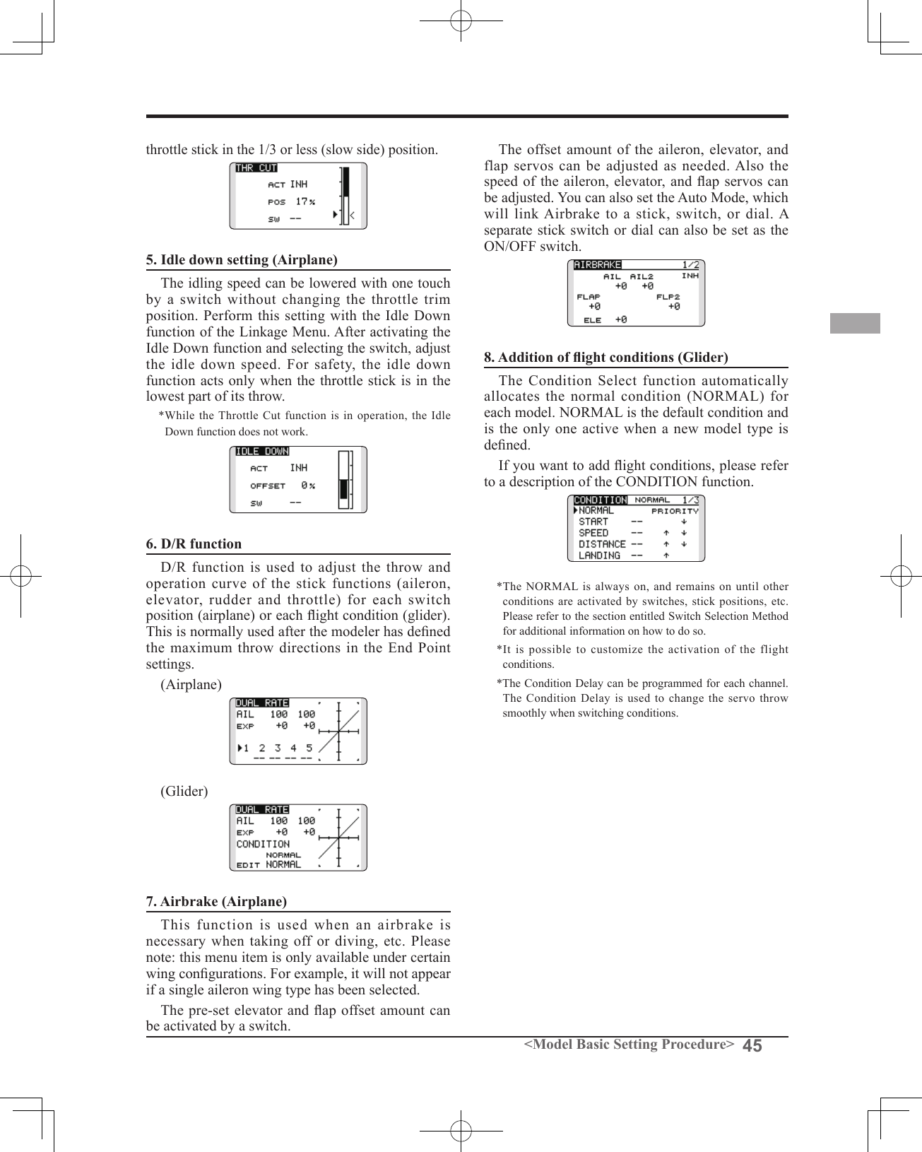
![47<Model Basic Setting Procedure>5. Throttle/Pitch curve settingThis function adjusts the throttle or pitch operation curve in relation to the movement of the throttle stick for each condition.<Throttle curve setting example>Activate the throttle curve of each condition with the condition select switch.●NormalcurveadjustmentNormalcurvecreates abasicthrottlecurvecenterednearhovering.Thiscurveis adjustedtogetherwiththe pitchcurve(Normal)sothattheenginespeedis constantandup/downcontroliseasiest.●IdleupcurveadjustmentThelowsideThrottlecurvecreates acurvematchedforaerobatics(loop,roll,3D,etc.).●ThrottleholdcurveadjustmentConrmthattherateoftheslowestposition(0%)ofthestickis0%(initialsetting).<Example of pitch curve setting>Activate the pitch curve of each condition with the condition select switch.●Pitchcurve(Normal)Makethepitchathoveringapproximately+5º~6º.Setthepitchathoveringwiththestickpositionatthe50%pointasthestandard.*Stability at hovering may be connected to the throttle curve. Adjustment is easy by using the hovering throttle function and hovering pitch function together.●Pitchcurve(Idleup1)Theidleup 1pitchcurvefunctioncreates acurvematchedtoairborneight.Setto-7º~+12ºasstandard.●Pitchcurve(Idleup2)Thehighsidepitchsettingislessthanidleup1.Thestandardis+8º.●Pitchcurve(Hold)Atautorotation,usethemaximumpitchatboththehighandlowsides.[Pitchanglesettingexample]Throttlehold:-7º~+12º4. Servo ConnectionConnect the throttle rudder, aileron, elevator, pitch, and other servos in accordance with the kit instruction manual. For a description of the connection method, see "Receiver and Servos Connection". Note: The channel assigned to each function can be checked at the Function menu of the Linkage Menu.●Ifthedirectionofoperationoftheservoisincorrect,usetheReversefunctionoftheLinkageMenu.AlsousetheswashAFRfunctioninotherthantheH-1mode.●Adjustthedirectionofoperationofthegyro.(Gyrosidefunction)●Connectthethrottlelinkagesothatthecarburetorcanfullycloseatfulltrimthrottlecut.●AdjusttheneutralpositionatthelinkagesideandnetunewiththeSub-TrimfunctionandEndPointfunction.Toprotectthelinkage,alimitpositioncanalsobesetwiththeEndPointfunction.●Swashplatecorrection(ExceptH-1mode)*If any interactions are noticed, for a description of the linkage correction function, please refer to the SWASH function.](https://usermanual.wiki/Futaba/T14SG-24G.User-Manual-2/User-Guide-1894989-Page-17.png)
![50 <Functions of System Menu>SYSTEM MENUSystem Menu functions table[TRAINER]: Starts and sets the trainer system.[DISPLAY]: LCD and back-light adjustment[USER NAME]: User name registration[SOUND]: Turns off the buzzer.[H/W SET]: H/W reverse, calibration and stick mode[START SEL.]: Immediately, a model selection can be performed[AUTO LOCK]: The automatic lock function of two kinds of touch sensors[INFO]: Displays the program version, SD card information, product ID, and language selection.[SBUS SERVO]: S.BUS servo setting.The System Menu sets up functions of the transmitter: This does not set up any model data.● Call the system menu shown below by touching the SYS button twice at the home screen, etc.● Select [SYSTEM MENU] and return to the home screen by touching the RTN button. Or a HOME/EXIT button is pushed.●Access setup screen<SensorTouch™>● Select the function you want to set and call the setup screen by touching the RTN button.Scrolling● Moving cursorRETURN](https://usermanual.wiki/Futaba/T14SG-24G.User-Manual-2/User-Guide-1894989-Page-20.png)
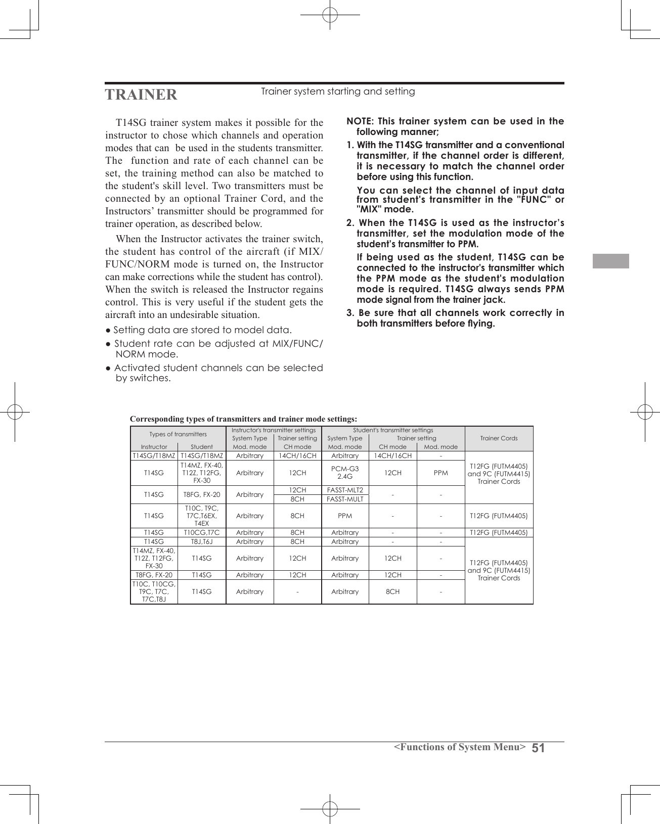
![52 <Functions of System Menu>● Select the function name and return to the System menu by touching the RTN button. Or the HOME/EXIT button is pushed.<SensorTouch™>RETURNMode and switch selection1. Access the setup screen page 4 shown below by touching the S1 button three times.2. Move the cursor to the [ACT] or [12/8CH] item and touch the RTN button to switch to the data input mode.3. Select the mode by scrolling the touch sensor. The display blinks. Touch the RTN button to change the mode. (To terminate the mode change, touch the S1 button.) "ACT": Enable operation by changing to [OFF] or [ON]. "12/8 CH": When the student uses the T14SG, T14MZ, T12Z, T12FG or FX-40, select [12CH]. Otherwise select [8CH].If changing the trainer switch:4. Move the cursor to the [SW] item and touch the RTN button to access the switch setup screen. (See "Switch selection method" at the end of this manual for selection method details.) "SW": Select the desired switch. Initial setting: SH*The switch mode can also be selected when setting the ON position on the switch setup screen. When [ALTERNATE OFF] is selected, normal ON/OFF operation is performed. When [ALTERNATE ON] is selected, the trainer function is alternately turned on and off each time the switch is operated. This allows alternate ON/OFF switching even when a momentary switch (SH) is used.● Select [TRAINER] in the System menu and enter the setup screen shown below by touching the RTN button. Note: The trainer function won’t be turned on unless the Instructor's transmitter receives signals from the student's transmitter. Be sure to confirm this after connecting your trainer cable.Operating mode selection(Setup screen page 1-3)1. Move the cursor to the [MODE] item of the channel you want to change and touch the RTN button to switch to the data input mode.2. Select the mode by scrolling the touch sensor. The display blinks. Touch the RTN button to change the mode. (To terminate the mode change, touch the S1 button.) "MODE": Select the desired operation mode for each channel. NORM: The model is controlled by signals from the student transmitter. MIX mode: The model is controlled by signals from the instructor and student transmitters. (Reset the student's model data to the default condition.) FUNC mode (function mode): The model is controlled by signals from the student transmitter with the instructor 's setting. (Reset the student's model data to the default condition.) OFF: Only the instructor side operates.Adjusting the student's rate.*This can be adjusted for students who may need lower rates than a more experienced student.Scrolling● Moving cursor● Selecting mode● Adjusting value● To next page](https://usermanual.wiki/Futaba/T14SG-24G.User-Manual-2/User-Guide-1894989-Page-22.png)
![53<Functions of System Menu>1. Move the cursor to the [RATE] item of the channel you want to change and touch the RTN button to switch to the data input mode.2. Adjust the rate by scrolling the touch sensor. "RATE": Adjust the desired rate. Setting range: 0~100% Initial value: 100%*When you want to reset the value to the initial state, touch the RTN button for one second.3. To end adjustment, touch the RTN button and return to the cursor mode.Changing the student's channel*The setting above allows setting of the channel assignment of student side when [MIX] or [FUNC] was selected.1. Move the cursor to the [STU. CH] item of the channel you want to change and touch the RTN button to switch to the data input mode.2. Select the channel by scrolling the touch sensor. The display blinks. Touch the RTN button to change the channel. (To terminate the mode change, touch the S1 button.) "STU. CH": Match the channel order of the Instructor's and student's transmitter. This function will help if both transmitters are in different modes, or the Master has a different wing type set up. The student can be set to match the Master without any physical changes being made.](https://usermanual.wiki/Futaba/T14SG-24G.User-Manual-2/User-Guide-1894989-Page-23.png)
![54 <Functions of System Menu>● Select the function name and return to the System menu by touching the RTN button. Or the HOME/EXIT button is pushed.<SensorTouch™>RETURNLCD contrast adjustment1. Select "CONTRAST" and touch the RTN button to switch to the data input mode and adjust the contrast by scrolling the touch sensor. "CONTRAST": Adjust the contrast to the desired value while watching the screen display. Setting range: (Lighter) 0 to 15 (Darker) Initial value: 5*When you want to reset the value to the initial state, touch the RTN button for one second.2. Touch the RTN button to end adjustment and return to the cursor mode.Back-light brightness adjustment1. Select "BRIGHTNESS" and touch the RTN button to switch to the data input mode and adjust the back-light brightness by scrolling the touch sensor. "BRIGHTNESS": Adjust the brightness to the desired value while watching the screen display. Setting range: OFF, 1 to 20(Lighter) Initial value: 10*When you want to reset the value to the initial state, touch the RTN button for one second.DISPLAY LCD and back-light adjustment, unit systemLCD contrast, back-light brightness and back-light off-timer adjustment are possible:Moreover, a display unit can be chosen from the metric system or yard/pound. 2. Touch the RTN button to end adjustment and return to the cursor mode.Back-light off-timer1. Select "OFF TIMER" and touch the RTN button to switch to the data input mode and adjust the back-light off-timer by scrolling the touch sensor. "OFF TIMER": Adjust the time when the back-light turns off after operating the touch sensor. Setting range: 10 to 240 sec (each 10 sec), OFF (always on) Initial value: 10 sec*When you want to reset the value to the initial state, touch the RTN button for one second.2. Touch the RTN button to end adjustment and return to the cursor mode.Unit system adjustment1. Select "UNIT SYS." and touch the RTN button to switch to the data input mode and adjust the unit by scrolling the touch sensor. Setting range: (METRIC) or (YARD/POUND) 2. Touch the RTN button to end adjustment and return to the cursor mode.● Select [DISPLAY] at the system menu and access the setup screen shown below by touching the RTN button.Scrolling● Moving cursor● Adjusting value](https://usermanual.wiki/Futaba/T14SG-24G.User-Manual-2/User-Guide-1894989-Page-24.png)
![55<Functions of System Menu>● Select the function name and return to the System menu by touching the RTN button. Or the HOME/EXIT button is pushed.<SensorTouch™>RETURNUSER NAME User name registrationThis function allows the modelers to change the T14SG user name.*A name of up to 10 characters can be entered as the user name. Please note that a space is also counted as one character.User name registration1. Change the user name as described below: [Moving cursor in user name (candidate)] Select [←] or [→], and touch the RTN button. [Deleting a character] When [DELETE] is selected and the RTN button is touched, the character immediately after the cursor is deleted. [Adding a character] When a character is selected from the character list and the RTN button is touched, that character is added at the position immediately after the cursor.*A name of up to 10 characters long can be entered as the user name. (A space is also counted as 1 character.)2. Upon completing the input, select [ENTER] and touch the RTN button. (To terminate input and return to the original state, select [CANCEL] and touch the RTN button.)(Character list 1/3)(Character list 2/3)(Character list 3/3)● Select [USER NAME] at the System menu and access the setup screen shown below by touching the RTN button.User name (candidate)Scrolling● Moving cursor](https://usermanual.wiki/Futaba/T14SG-24G.User-Manual-2/User-Guide-1894989-Page-25.png)
![56 <Functions of System Menu>● Select the function name and return to the System menu by touching the RTN button. Or the HOME/EXIT button is pushed.<SensorTouch™>RETURNSOUND Turns off the buzzer.The warning sound and other sounds of the T14SG transmitter can be turned off.*When “WARNING” was set to OFF, the no operation alarm (30 minutes), mixing warning sound, and low battery alarm sounds also turned off. ● Select [SOUND] at the system menu and access the setup screen shown below by touching the RTN button.On/off operation1. Move the cursor to the [TIMER][WARNING] or [OTHER SOUND] item and touch the RTN button to switch to the data input mode.2. Select the ON or OFF by scrolling the touch sensor.*The display blinks.3.Touch the RTN button.Scrolling● Moving cursor● Selecting mode](https://usermanual.wiki/Futaba/T14SG-24G.User-Manual-2/User-Guide-1894989-Page-26.png)
![57<Functions of System Menu>● Select the function name and return to the System menu by touching the RTN button. Or the HOME/EXIT button is pushed.<SensorTouch™>RETURNOperation direction reversal method1. Select [H/W REVERSE] and access the setup screen shown below by touching the RTN button.2. Move the cursor to the item corresponding to the H/W (hardware) you want to reverse and touch the RTN button to switch to the data input mode.3. Select the mode by scrolling the touch sensor. The display blinks. When the RTN button is touched, the operation direction is reversed. (To terminate the mode change, touch the S1 button.) "NORM": Normal operation direction "REV" : Operation direction is reversed.H/W SETTING Hardware reverse and stick modeH/W reverseThis function reverses the operation direction of the sticks, switches, trimmer levers, and knobs.Note: This setting reverses the actual operation signal, but does not change the display indicators. Use the Normal mode as long as there is no special reason to use the Reverse mode.Stick modeThis function changes the stick mode of transmitter.Note: This will not change the throttle ratchet, etc. Those are mechanical changes that must be performed by a Futaba service center.Note: After changing the mode, these changes are only applied to new models. It is not applied to an existing model.Stick calibrationJ1-J4 stick correction can be performed.● Select [H/W SET] at the system menu and access the setup screen shown below by touching the RTN button.Changing stick mode1.Select [STICK MODE] and access the setup screen shown below by touching the RTN button.2. Move the cursor to the "STICK MODE" item and touch the RTN button to switch to the data input mode.3. Select the mode. The display blinks. When the RTN button is touched, the stick mode is changed. (To terminate the mode change, touch the S1 button.) (J1)(J2)(J4)(J3)Mode J1 J2 J3 J41 Aileron Throttle Elevator Rudder2 Aileron Elevator Throttle Rudder3 Rudder Throttle Elevator Aileron4 Rudder Elevator Throttle Aileron●Access setup screenScrolling● Moving cursor](https://usermanual.wiki/Futaba/T14SG-24G.User-Manual-2/User-Guide-1894989-Page-27.png)
![58 <Functions of System Menu>Stick calibration method*J3 and J4 correction is described below. J1 and J2 corrections are performed using the same procedure. 1.Select [CALIBRATION] and access the setup screen shown below by touching the RTN button.2.Move the cursor to the J3-J4 button and touch the RTN button.3.Move the J3 or J4 sticks to the neutral position and press the RTN button for one second.4.Set the J3 and J4 sticks fully to the bottom right and wait until the buzzer sounds.5.Set the J3 and J4 sticks fully to the top left and wait until the buzzer sounds.6.The above completes the correction operation. Operate and check if stick correction was performed normally.](https://usermanual.wiki/Futaba/T14SG-24G.User-Manual-2/User-Guide-1894989-Page-28.png)
![62 <Functions of System Menu>● Select the function name and return to the System menu by touching the RTN button. Or the HOME/EXIT button is pushed.<SensorTouch™>RETURN●Lock releaseEvery lock function's touch [ 1 second or more ] of S1 button will release the lock.●Lock releaseEvery lock function's touch [ 1 second or more ] of HOME/EXIT button will release the lock.● Manual lockIf S1 button is touched 1 second or more from a HOME screen, a SensorTouch locks manually.● Manual lockIf HOME/EXIT button is touched 1 second or more from a HOME screen, a SensorTouch locks manually.●Display of a lockIf locked, there will be sound and the icon of a key will come out.Auto lock method1. Open the Auto lock screen in the system menu.2. Adjust the activation timer for the Auto Lock function. The timer will begin counting immediately when the HOME screen is not used. The timer is adjustable in one second increments up to 30 seconds. If the timer value is OFF, this function is not applicable.3.The Start Lock setting will, if enabled, automatically lock the T14SG when the transmitter is powered up. To allow access to the transmitter's functions, press and hold the S1 key for one second.*If neither the Lock Timer or Start Lock functions are active (OFF), then the key lock remains even if the power is turned off.*If the Lock Timer is enabled and the Start Lock is off, the key lock status is canceled each time the T14SG is turned on.The Auto Lock function makes it possible to lock the transmitter to prevent any unwanted input from your hands while ying. The auto lock function can be set in two ways.LOCK TIMERAuto Lock functions automatically when there is no operation from the HOME screen display for a chosen number of seconds.START LOCKAuto Lock functions automatically when the model changes or power is turned on.*To temporarily allow access to the T14SG programming press and hold the S1 or HOME/EXIT bitton for one second. Please note, the Auto Lock function timer will resume immediately once again.AUTO LOCK The automatic lock function of two kinds of SensorTouchDangerIt is recommended to Lock the SensorTouch during ight, to prevent any accidental touches which could change settings and cause an accident.](https://usermanual.wiki/Futaba/T14SG-24G.User-Manual-2/User-Guide-1894989-Page-32.png)
![63<Functions of System Menu>● Select the function name and return to the System menu by touching the RTN button. Or the HOME/EXIT button is pushed.<SensorTouch™>RETURNINFO Displays the program version, SD card information, and product ID.The T14SG system program version information, SD card information (current and maximum number of model data and other les), and product ID are displayed on the Information screen.*When the SD card is not inserted, the SD card information is not displayed.The language displayed in home, menu, and setup screen is selectable.● Select [INFO] at the system menu and access the setup screen shown below by touching the RTN button.Information "PRODUCT": Product ID number "RF ID": RF ID number "LANGUAGE": The language used in T14SG "VERSION": T14SG system program version information "AREA": Area which can use T14SG "CARD SIZE": Current/Maximum number of model data and other les (SD card)Language selection1. Move the cursor to the "LANGUAGE" item and touch the RTN button to switch to the data input mode.2. Change the language by scrolling the touch sensor. The display blinks. When the RTN button is touched, the language is changed. (To terminate the change, turn the EDIT dial or push the S1 button.)Scrolling● Moving cursor● Selecting mode](https://usermanual.wiki/Futaba/T14SG-24G.User-Manual-2/User-Guide-1894989-Page-33.png)
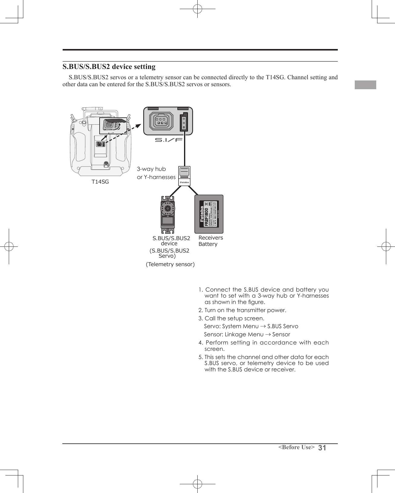
![64 <Functions of System Menu>● Select the function name and return to the System menu by touching the RTN button. Or the HOME/EXIT button is pushed.<SensorTouch™>RETURNSBUS servo setting.An S.BUS servo can memorize the channel and various settings you input. Servo setting can be performed on the T14SG screen by wiring the servo as shown in the figure.● Select [SOUND] at the system menu and access the setup screen shown below by touching the RTN button.Scrolling● Moving cursor● Selecting modeServo ID numberIndividual ID numbers are memorized for your S.BUS(2) servos in your T14SG. When a servo is used, the servo ID number is automatically read by the transmitter. If you use multiple S.BUS(2) servos and do not want to change the settings on all that are mounted in a fuselage, only the desired servo in the group can be set by entering the ID of that specic servo.* S9070SB cannot be arranged by T14SG. * With some S.BUS(2) servos, there are some functions with cannot be used. If a function cannot be used, the display screen will change. (Only the function which can be used by a servo is displayed.)* After reading completion, with connection of the above gure, if a stick is moved, the test of operation of the servo can be operated and carried out.Procedure for changing S.BUS servo setting1. Select [SBUS SERVO] of the System Menu.2. Wire the servo as shown in the gure above.3. Press [RECALL] on page 3(S1 is pushed twice). The ID and current setting of that servo are displayed. ([RECALL] is chosen ⇒RTN is pushed ⇒RTN is pushed for 1 second)4. When multiple servos are connected change [INH] at the right side of the ID number on the screen to [ACT] and enter the ID of the servo you want to set.5. Set each item. (Please see the next page.) 6. Press [WRITE] on page 3([WRITE] is chosen ⇒RTN is pushed ⇒RTN is pushed for 1 second). The settings are changed. Push [INIT.], if you would like to initialize a setup of a servo. ([INIT.] is chosen ⇒RTN is pushed ⇒RTN is pushed for 1 second)S.BUS/S.BUS2 ServoBatteryT14SG3-way hub or Y-harnessesSBUS SERVO](https://usermanual.wiki/Futaba/T14SG-24G.User-Manual-2/User-Guide-1894989-Page-34.png)
![65<Functions of System Menu>S.BUS Servo Description of function of each parameter*There are a function which can be used according to the kind of servo, and an impossible function. • IDDisplays the ID of the servo whose parameters are to be read. It cannot be changed.• ChannelChannel of the S.BUS system assigned to the servo. Always assign a channel before use.• ReverseThe direction in which the servo rotates can be changed.• Servo typeWhen “Retractable” is selected and the servo has been continuously stopped for 30 seconds, the dead band expands and unnecessary hold current due to external force is eliminated. When a new control signal enters, normal operation is resumed. When using the servo as a landing gear servo, select “Retractable”. Also adjust the servo travel to match the landing gear movement range.• Soft StartRestricts operation in the specified direction the instant the power is turned on. By using this setting, the first initial movement when the power is turned on slowly moves the servo to the specified position.• Stop Mode The state of the servo when the servo input signal is lost can be specified. The "Hold" mode setting holds the servo in its last commanded position even if using AM or FM system.• SmootherThis function changes smoothness of the servo operation relative to stick movement changes. Smooth setting is used for normal flight. Select the "OFF" mode when quick operation is necessary such as 3D.• Neutral OffsetThe neutral position can be changed. When the neutral offset is large value, the servo's range of travel is restricted on one side.• Speed ControlSpeeds can be matched by specifying the operating speed. The speed of multiple servos can be matched without being affected by motor fluctuations. This is effective for load torques below the maximum torque.However, note that the maximum speed will not be exceed what the servo is capable of even if the servos operating voltage is increased. • Dead bandThe dead band angle at stopping can be specified.[Relationship between dead band set value and servo operation]Small → Dead band angle is small and the servo is immediately operated by a small signal change.Large → Dead band angle is large and the servo does not operate at small signal changes.(Note) If the dead band angle is too small, the servo will operate continuously and the current consumption will increase and the life of the servo will be shortened.• Travel AdjustThe left and right travels centered about the neutral position can be set independently.• BoostThe minimum current applied to the internal motor when starting the servo can be set. Since a small travel does not start the motor, it essentially feels like the dead band was expanded. The motor can be immediately started by adjusting the minimum current which can start the motor.[Relationship between boost set value and servo operation]Small → Motor reacts to a minute current and operation becomes smooth.Large → Initial response improves and output torque increases. However, if the torque is too large, operation will become rough.](https://usermanual.wiki/Futaba/T14SG-24G.User-Manual-2/User-Guide-1894989-Page-35.png)
![66 <Functions of System Menu>• Boost ON/OFFOFF : It is the boost ON at the time of low-speed operation.(In the case of usual)ON : It is always the boost ON.(When quick operation is hope)• DamperThe characteristic when the servo is stopped can be set.When smaller than the standard value, the characteristic becomes an overshoot characteristic. If the value is larger than the standard value, the brake is applied before the stop position.Especially, when a large load is applied, overshoot, etc. are suppressed by inertia and hunting may occur, depending on the conditions. If hunting (phenomena which cause the servo to oscillate) occurs even though the Dead Band, Stretcher, Boost and other parameters are suitable, adjust this parameter to a value larger than the initial value.[Relationship between damper set value and servo operation]Small → When you want to overshoot. Set so that hunting does not occur.Large → When you want to operate so that braking is not applied. However, it will feel like the servo response has worsened.(Note) If used in the hunting state, not only will the current consumption increase, but the life of the servo will also be shortened.• StretcherThe servo hold characteristic can be set. The torque which attempts to return the servo to the target position when the current servo position has deviated from the target position can be adjusted.This is used when stopping hunting, etc., but the holding characteristic changes as shown below.[Relationship between stretcher and servo operation]Small → Servo holding force becomes weaker.Large → Servo holding force becomes stronger.(Note) When this parameter is large, the current consumption increases.• BuzzerWhen the power supply of a servo is previously turned on at the time of a power supply injection without taking transmit of a transmitter, the buzzer sound of about 2.5 Hz continues sounding from a servo. (Even when the transmit of a transmitter is taken out previously, a buzzer becomes until the signal of a servo is outputted normally, but it is not unusual.) The transmitter has been turned OFF ahead of a servo power supply → The buzzer sound of about 1.25 Hz continues sounding as servo power supply end failure alarm.(Do not insert or remove the servo connector while the receiver power is ON. A buzzer may sound by incorrect recognition.) * Buzzer sound is generated by vibrating the motor of a servo. Since current is consumed and a servo generates heat, please do not operate the number more than needed or do not continue sounding a buzzer for a long time.](https://usermanual.wiki/Futaba/T14SG-24G.User-Manual-2/User-Guide-1894989-Page-36.png)
![67<Functions of Linkage Menu>FUNCTIONS OF LINKAGE MENUThe Linkage Menu is made up of functions which perform model addition, model type selection, system type, end point setting, and other model basic settings.The functions which can be selected depend on the model type. A typical menu screen is shown below.*The display screen is an example. The screen depends on the model type.Linkage Menu functions table[SERVO]: Displays the servo test and operation position[MODEL SEL]: Model addition, call, deletion, copy, model name setting[MODEL TYPE]: Model type, wing type, swash type, etc. selection[SYSTEM]: System mode selection, link of a transmitter and receiver, area mode selection[FUNCTION]: Channel assignment of each function can be changed[SUB-TRIM]: Adjusts the neutral position of each servo[REVERSE]: Reverses the servo travel direction[FAIL SAFE]: Fail safe function and battery fail safe function setting[END POINT]: Servo travel adjustment and limit setting[SERVO SPEED]: Speed setup of a servo[THR CUT]: Stops the engine safely and easily (airplane and helicopter only)[IDLE DOWN]: Lowers the idle speed of the engine (airplane only)[SWASH RING]: Limits the swash plate travel to within a xed range. (helicopter only)[SWASH]: Swash AFR and linkage correction function (helicopter only)[T1-T4 SET.]: Control step amount and mode selection of the digital trim[WARNING]: Mixing warning normal reset [TELEMETRY]: Displays various data sent from the receiver.[SENSOR]: Various telemetry sensors setting[DATA RESET]: Model memory set data reset● Access the Linkage menu shown below by tapping the LNK button two times.● Select the function name and return to the Linkage menu by touching the RTN button. Or a HOME/EXIT button is pushed.<SensorTouch™>● Select the function you want to set and call the setup screen by touching the RTN button. ●Calling setup screenScrolling● Moving cursorRETURN](https://usermanual.wiki/Futaba/T14SG-24G.User-Manual-2/User-Guide-1894989-Page-37.png)
![68 <Functions of Linkage Menu>● Select the function name and return to the Linkage menu by touching the RTN button. Or the HOME/EXIT button is pushed.<SensorTouch™>RETURNSERVO MONITOR Servo Test & Graph Display / Displays servo positions.This is used for testing servo movement. “Moving Test” (repetition mode) and “Neutral Test” (xed position mode) are available. The “Neutral Test” is good for finding the neutral position of a servo horn.In order to prevent any potential difficulties, the servo test function will be inoperable, or inaccessible, under certain conditions. Specically, the Servo Test function is not operational if the Throttle Cut is ON in either airplane or helicopter modes; or if the Throttle Hold is ON in Helicopter mode.● Select [SERVO] in the Linkage menu and access the setup screen shown below by touching the RTN button.● A [U.MENU/MON.] button is pushed once from a home screen.Servo test operation1. Move the cursor to the [OFF] item and touch the RTN button to switch to the data input mode. Select the test mode by scrolling the touch sensor and touch the RTN button. The display blinks. Touch the RTN button to change the mode. (To terminate mode change, touch the S1 button.) [MOVING]: Mode which repeats operation of each servo [NEUTRAL]: Mode which locks each servo in the neutral position2. Move the cursor to the [MOVING] or [NEUTRAL] item and touch the RTN button to switch to the data input mode. Select the [OFF] by scrolling the touch sensor and touch the RTN button. Testing is stopped.Scrolling● Moving cursor● Selecting mode](https://usermanual.wiki/Futaba/T14SG-24G.User-Manual-2/User-Guide-1894989-Page-38.png)
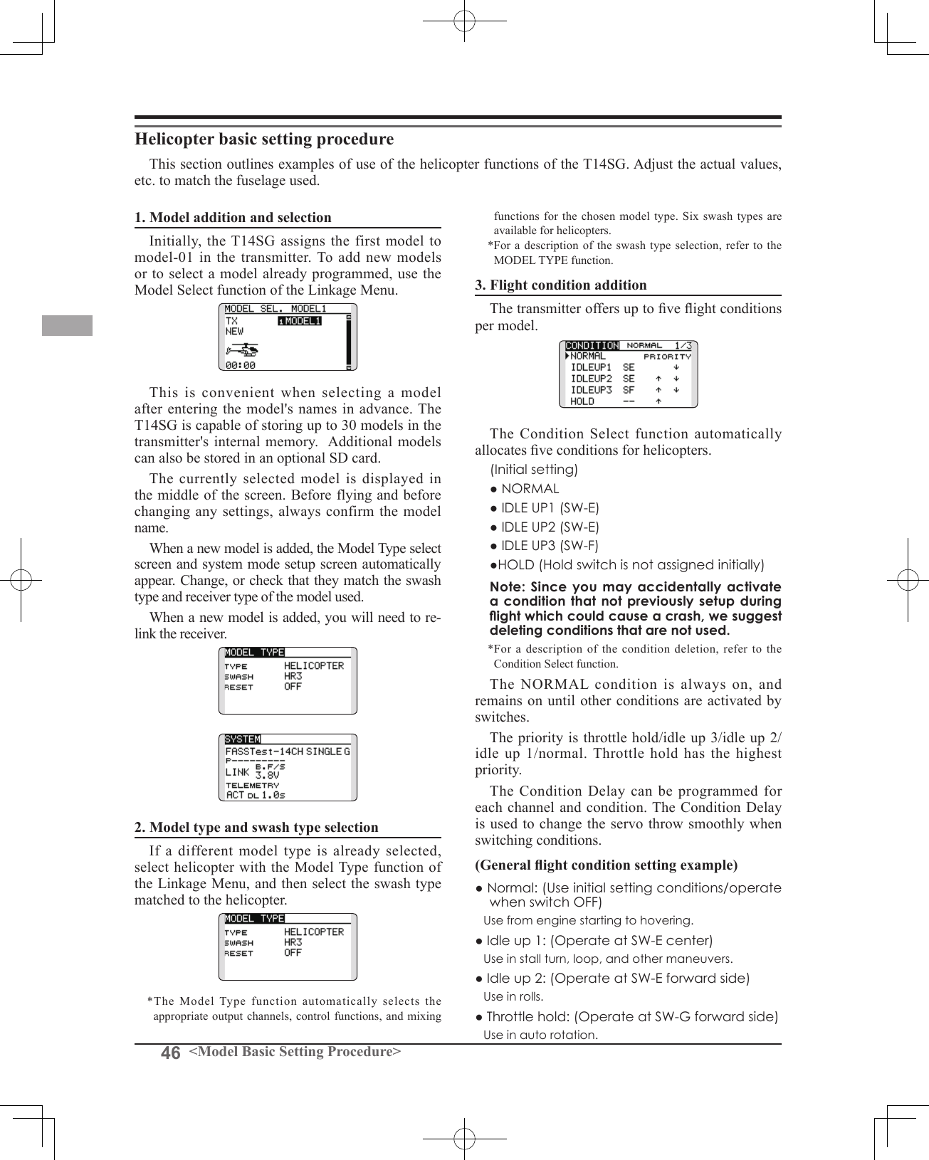
![69<Functions of Linkage Menu>● Select the function name and return to the Linkage menu by touching the RTN button. Or the HOME/EXIT button is pushed.<SensorTouch™>RETURNMODEL SELECT The Model Selection function performs model addition, selection, deletion, copy, and model name setting. This function is used to load the settings of the desired model into the T14SG’s memory.The settings may be selected from either the transmitter’s internal memory or an SD card. Remember that up to 30 model memories are available in the transmitter.The name of the model stored in the transmitter and the SD card may be changed. This can be very useful to tell different models settings apart. Each model name can be as long as 10 characters, and the model name always appears in the display screen.The Copy function is used to copy parameters, settings, etc. from one model data into a second memory. It may be used for getting a head-start on setting up models with almost the same settings (only differences need to be modied, instead of entering the complete model from scratch). Also, this function may be used to make a backup copy of a model setup before any changes are made.*T14SG can use the model data of T8FGS for SD card, copying it. However, the model data of T14SG cannot be used by T8SG (S).Model selection*Model data saved on the transmitter memory other than the model currently used can be selected.1. Move the cursor to the save destination display ("TX" or "CARD") and touch the RTN button to switch to the data input mode. Select the save destination by scrolling the touch sensor and touch the RTN button. [TX]: Transmitter memory [CARD]: SD card2. After moving the cursor to the desired model in the model list, touch the RTN button.3. Move to [SELECT].4.Touch the RTN button. A confirmation message is displayed. Touch the RTN button for one second and selection is complete.*Transmission stops and then starts in the new model.Model addition*A new model can be added to the transmitter memory. It can not be added to the SD card.1. Move the cursor to [NEW]. 2. Touch the RTN button. A confirmation message appears. Touch the RTN button for one second.*The model type setup screen and frequency setup screen are automatically displayed. Conrm or change the model type and SYSTEM mode.*Transmission stops and then starts in the new model.*The added model appears in the model list of the model select setup screen.*Link is required when a new model is made from a model selection.● Select [MODEL SELECT] in the Linkage menu and access the setup screen shown below by touching the RTN button.*The display screen is an example. The screen depends on the model type.Scrolling● Moving cursor● Selecting mode(Model list)Current model](https://usermanual.wiki/Futaba/T14SG-24G.User-Manual-2/User-Guide-1894989-Page-39.png)
![70 <Functions of Linkage Menu>Model deletion*The model stored in the transmitter memory or an SD card can be deleted.*The current model can not be deleted.1. Move the cursor to the save destination display ("TX" or "CARD") and touch the RTN button to switch to the data input mode. Select the save destination by scrolling the touch sensor and touch the RTN button. [TX]: Transmitter memory [CARD]: SD card2. Move the cursor to the model you want to delete in the model list and then touch the RTN button.3. Move the cursor to [DELETE].4. Touch the RTN button. When a conrmation message is displayed and the RTN button is touched for one second, the model is deleted.Model name change*The model name of the model stored in the transmitter memory or a SD card can be changed.1. If changing the location: Move the cursor to the save destination display ("TX" or "CARD") and touch the RTN button to switch to the data input mode. Select the save destination by scrolling the touch sensor and touch the RTN button. [TX]: Transmitter memory [CARD]: SD card2. Move the cursor to the model you want to change in the model list and then touch the RTN button.3. Move to [RENAME].4. Touch the RTN button.*The model name setup screen is displayed. User name (candidate)5. Change the model name as described below: [Moving cursor in the user name (candidate)] Select [←] or [→], and touch the RTN button. [Deleting a character] When [DELETE] is selected and the RTN button is touched, the character immediately after the cursor is deleted. [Adding a character] When a character is selected from the character list and the RTN button is touched, that character is added at the position immediately after the cursor.*A name of up to 10 characters long can be entered as the model name. (A space is also counted as one character.)6. After the desired information has been input, select [ENTER] and touch the RTN button. (To terminate input and return to the original state, select [CANCEL] and touch the RTN button.)Model copy*A copy can be made of the model stored in the transmitter memory or an SD card.1. If changing the location: Move the cursor to the save destination display ("TX" or "CARD") and touch the RTN button to switch to the data input mode. Select the save destination by scrolling the touch sensor and touch the RTN button. [TX]: Transmitter memory [CARD]: SD card2. Select the model you want to copy in the model list and then touch the RTN button.3. Move to [COPY].4. Touch the RTN button.*The copy screen appears.5. If replacing the model stored in the transmitter memory: Move to [ADD-LIST] and touch the RTN button to switch to the data input mode. Select the destination model by scrolling the touch sensor and touch the RTN button. [ADD-LIST]: adding the model to the list [(model name)]: replacing the model*The model stored in the SD card can be replaced. If changing the location: Move the cursor to the copy destination display ("TX" or "CARD") and touch the RTN button to switch to the data input mode. Select the save destination by scrolling the touch sensor and touch the RTN button.6. Move to [COPY].7. Touch the RTN button. When a conrmation message is displayed and the RTN button is touched for one second, the model data is copied.](https://usermanual.wiki/Futaba/T14SG-24G.User-Manual-2/User-Guide-1894989-Page-40.png)
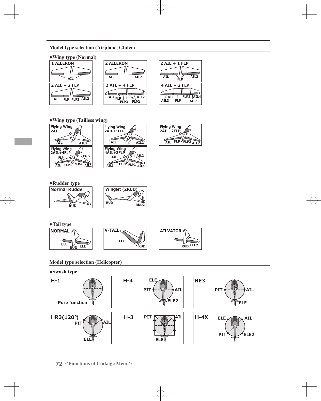
![71<Functions of Linkage Menu>● Select the function name and return to the Linkage menu by touching the RTN button. Or the HOME/EXIT button is pushed.<SensorTouch™>RETURNMODEL TYPE This function selects the model type from among airplane, helicopter, and glider.(The display screen is an example. The screen depends on the model type.) Six swash types are available for helicopters. Six types of main wings and three types of tail wings are available for airplanes and gliders. Functions and mixing functions necessary for each model type are set in advance at the factory.Note: The Model Type function automatically selects the appropriate output channels, control functions, and mixing functions for the chosen model type. When the Model Type selection command is accessed, all of the data in the active memory is cleared (except the following swash type.) Be sure that you don’t mind losing this data, or back it up to another memory using the copying functions. When changing the helicopter swash type within the following groups, you can leave the settings other than the SWASH function. However, this is initialized when you change the swash type to the other swash type group.Model type selection1. Move the cursor to the item you want to change and touch the RTN button to switch to the data input mode. Select the desired type by scrolling the touch sensor and touch the RTN button. A confirmation message appears. Touch the RTN button for one second. Move to [YES] and Touch the RTN button for one second. (To terminate input and return to the original state, touch the S1 button or select [NO] and touch the RTN button.) "TYPE": Model type "WING " (airplane/glider): Wing type "TAIL" (airplane/glider): Tail type "SWASH" (helicopter): Swash type*The wing types which can be selected depend on the mode; FASST, Multi-ch, or 7ch, etc.● Select [MODEL TYPE] in the Linkage menu and access the setup screen shown below by touching the RTN button.2. If resetting the data when changing the helicopter swash type:(Helicopter) Move the cursor to [OFF] and touch the RTN button to switch to the data input mode. Select [ON] by scrolling the touch sensor and touch the RTN button. A confirmation message appears. Touch the RTN button. Activate the swash type setting. The swash setting parameters are reset.Swash type group A:H-1, H-3, HR3, and HE3Swash type group B:H-4, H-4XScrolling● Moving cursor● Selecting mode](https://usermanual.wiki/Futaba/T14SG-24G.User-Manual-2/User-Guide-1894989-Page-41.png)
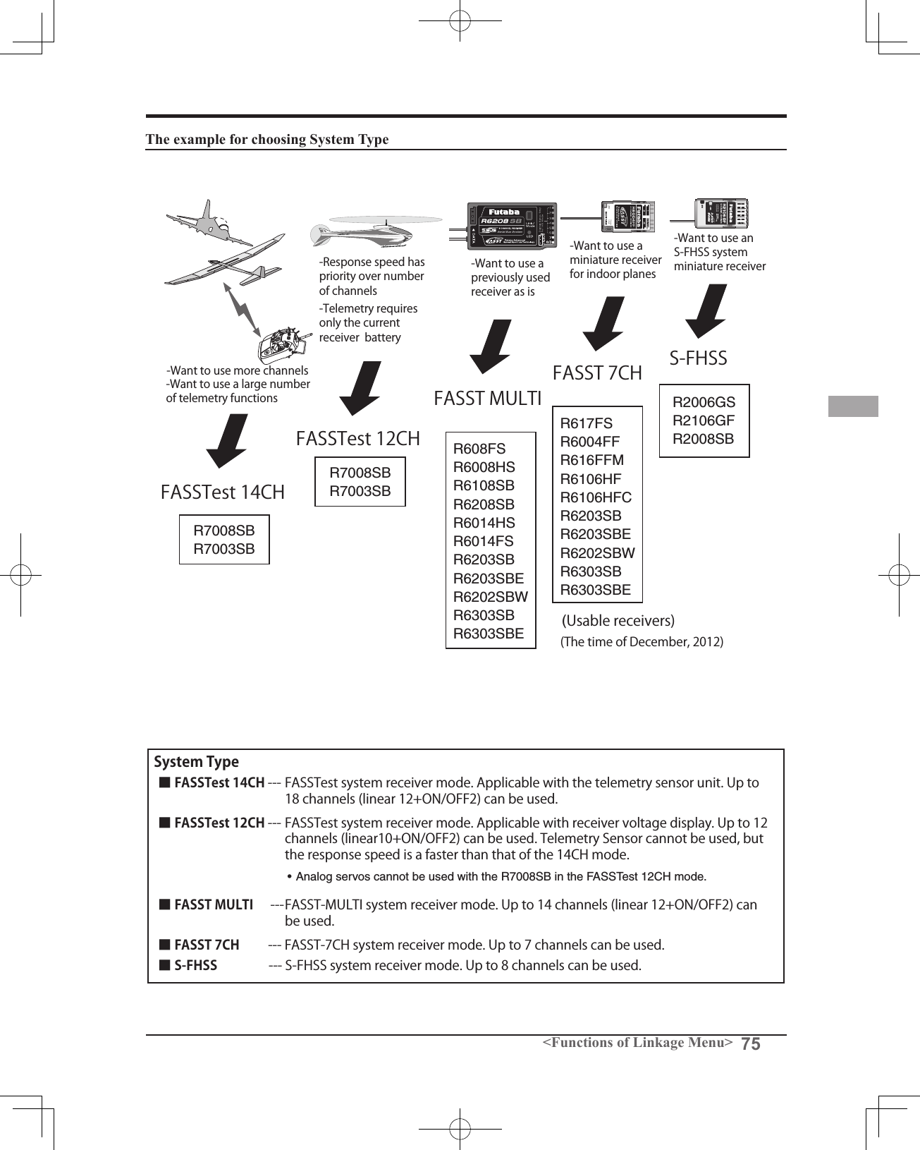
![73<Functions of Linkage Menu>● Select the function name and return to the Linkage menu by touching the RTN button. Or the HOME/EXIT button is pushed.<SensorTouch™>RETURNSystem Type selectionThe T14SG is for 2.4GHz only. The system can be changed from among 5 choices: FASSTest 14CH, FASSTest 12CH, FASST MULTI, FASST 7CH, S-FHSS. It is FASSTest14CH and FASSTest12CH which can be chosen by R7008SB set. The method of selection is to the next page.*If you change the System Type, other model data is not reset.*If a system type is changed in Helicopter mode, the transmitter will offer two selections:[Yes] : Selection sets the channel order suitable for System Type. (We recommend here. )[No] : The present channel order is maintained.*After any change, remember to test the model and should fully check servo direction and a motion.*Analog servos cannot be used with the R7008SB in the SYSTEM System mode setting, Receiver linkArea mode selection (Frequency range)The T14SG transmitter has been designed to function in many countries. If you will be utilizing this transmitter in a country other than France, please make sure that [AREA] is set to "G". If, however, this transmitter will be utilized in France, it must be set to "F" in order to comply with French regulations.FASST mode selectionReceiver linkingThe receiver will only be controlled (without being affected by other transmitters) by the transmitter it is linked to. When using a receiver other than one purchased as a set, linking is necessary.Moreover, a re-link is required when a new model is added by model selection, and the time of system type change.FASSTest 12CH mode.Dual receiver function (only FASSTest 14CH mode)Dual receivers can be linked with the T14SG. Two receivers are recognized individually by ID numbers. For example, in R7008SB, CH output setting function is used, by setting the first as as "1-8CH", and setting the second as "9-14CH", two sets of receivers can be used as a set in the model, allowing you 14 channels. If a Dual receiver function is used, the following function can set up individually.・Battery fail-safe voltage setup ・Telemetry function ON/OFF・Sensor setupBattery fail-safe voltage setup (only FASSTest mode)The voltage which battery fail-safe activates, can be set when you link. (3.5-8.4V) The receiver memorizes the setting as it was at link.Suggested setting voltages are as follows.• 4 cells NiCd or NiMH (Normal: 4.8v) = 3.8 v• 2 cells LiFe (Normal: 6.6 v) = 6.0 ~ 6.2 v• 2 cells LiPo (Normal: 7.4 v) = 7.2 ~ 7.4 vIt is a rough reference value.Since it changes with servos carried in the condition and the model of a battery, please set to your own model in a battery consumption current.● Select [SYSTEM] in the Linkage menu and access the setup screen shown below by touching the RTN button.Scrolling● Moving cursor● Selecting modeP.37Linking method Cases when linking is necessary:・When using a receiver other than the initial setting.・When the communication system was changed.(FASSTest14CH ↔FASSTest12CH etc. )・When a new model was created by model selection.](https://usermanual.wiki/Futaba/T14SG-24G.User-Manual-2/User-Guide-1894989-Page-43.png)
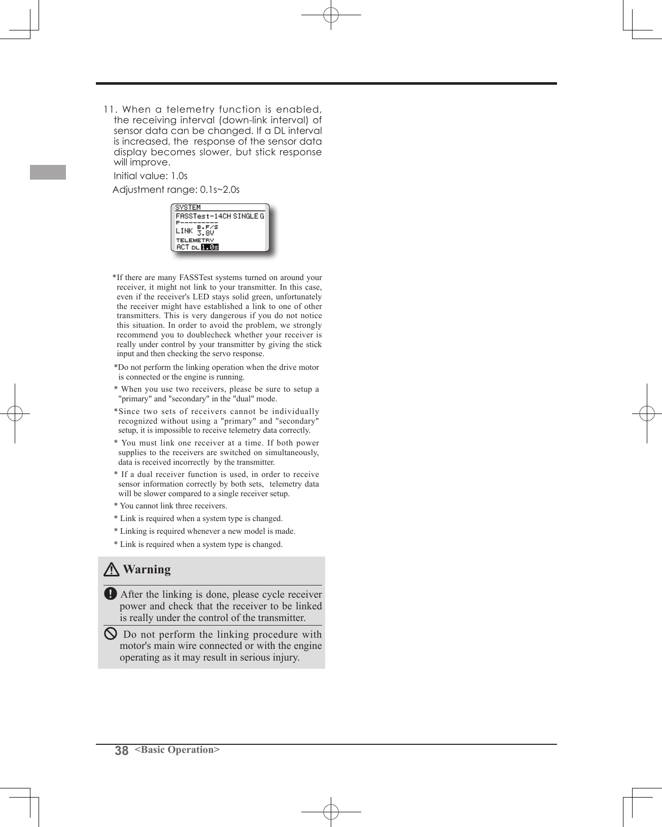
![74 <Functions of Linkage Menu>Telemetry function (FASSTest mode only)To use the telemetry function, set “Telemetry” to “ACT”.DL Interval (FASSTest mode only)When a telemetry function is enabled, the receiving interval (down-link interval) of sensor data can be changed. If a DL interval is increased, the response of the sensor data display becomes slower, but stick response will improve. System Type selection procedure1. Move the cursor to the [FASSTest-14CH] item and touch the RTN button to switch to the data input mode. 2. Select the system type by scrolling the touch sensor. [FASSTest-14CH][FASSTest-12CH][FASST-MULT][FASST-7CH][S-FHSS]*An example of selections for each system is on the following page.3. Touch the RTN button to end adjustment and return to the cursor mode.Dual receiver function (only FASSTest 14CH mode) procedure1. Move the cursor to the [SINGLE] item and touch the RTN button to switch to the data input mode. 2. Select the [SINGLE] or [DUAL] by scrolling the touch sensor.3. Touch the RTN button to end adjustment and return to the cursor mode.Area mode selection (Frequency range)procedure1. Move the cursor to the [G] item and touch the RTN button to switch to the data input mode. 2. Select the [G]or[F] by scrolling the touch sensor.*"F" is chosen only when using the transmitter is used in France. Leave this in "G" otherwise.3. Touch the RTN button to end adjustment and return to the cursor mode.Telemetry ACT/INH procedure1. Move the cursor to the TELEMETRY [ACT] item and touch the RTN button to switch to the data input mode. 2. Select the [ACT]or[INH] by scrolling the touch sensor.3. Touch the RTN button to end adjustment and return to the cursor mode.DL Interval set procedure1. Move the cursor to the TELEMETRY DL[1.0s] item and touch the RTN button to switch to the data input mode. 2. Select the DL time by scrolling the touch sensor. If a DL interval is increased, the response of the sensor data display becomes slower, but stick response will improve. Initial value: 1.0s Adjustment range : 0.1s~2.0s3. Touch the RTN button to end adjustment and return to the cursor mode.ID of a Primary receiver displays.ID of a Secondary receiver displays.In DUAL, a primary receiver is link previously. Next, a secondary receiver is link.](https://usermanual.wiki/Futaba/T14SG-24G.User-Manual-2/User-Guide-1894989-Page-44.png)
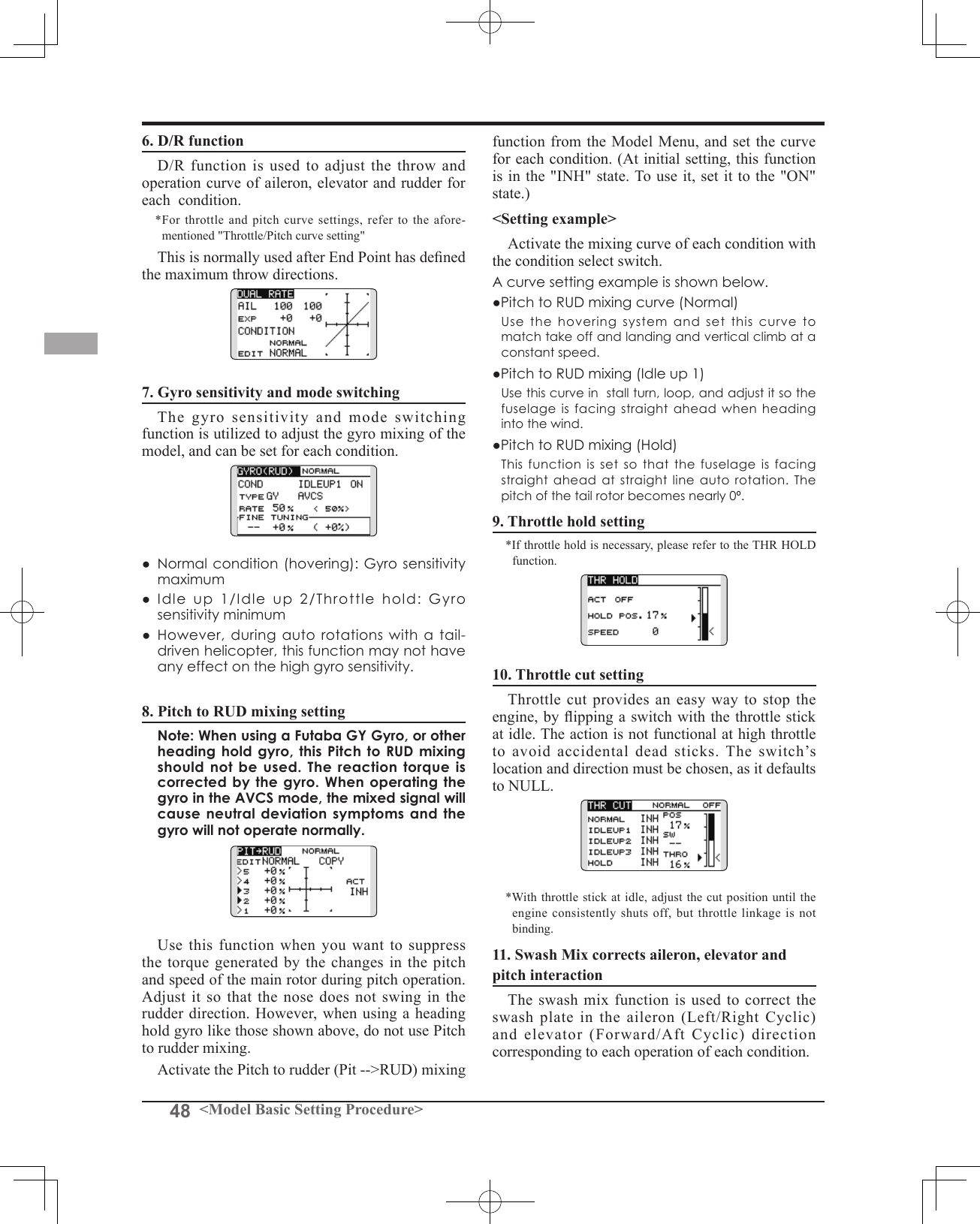
![76 <Functions of Linkage Menu>● Select the function name and return to the Linkage menu by touching the RTN button. Or the HOME/EXIT button is pushed.<SensorTouch™>RETURNFUNCTION Channel assignment of each function can be changed.When you select model and wing (swash) types, you will find that the optimized combinations of servo output channels and functions have been already preset. If you would like, you can freely change combinations of servo output channels, functions (aileron, elevator, etc), and control (sticks, switches, and trim levers). *You can also assign the same function to multiple servo output channels such as assigning elevator function to CH2 and CH3.Channel ReplacementWhen the channel is replaced in the Function menu, replaced channel uses the setting data (ATV, SUB-TRIM, REVERSE, F/S, and B-F/S, etc.).Servo Output ChannelsFor FASSTest 14CH mode, you can set 12 linear channels and two digital channels. For FASSTest 12CH mode, you can set 10 linear channels and two digital channels. For FASST MULT mode, you can set 12 linear channels and two digital channels.Function change1. Move the cursor to the function item of the channel you want to change and touch the RTN button.*The function selection screen is displayed.2. Move the cursor to the function name you want to set and touch the RTN button.*The function name blinks.3. Touch the RTN button to execute the change. (When you want to cancel this operation, touch the S1 button.)*Multiple channels can be assigned to one function.For FASST 7CH mode, you can set only 7 linear channels. For S-FHSS mode, you can set only 8 linear channels.*DG1/2 (digital channels) These channels can function as switched channels. You can freely change combinations between servo output channels and input controls (sticks, switches, and trim levers).Motor FunctionIf you have either a Glider or Airplane Model Type selected, and choose to activate the Motor function, a reverse setting screen is displayed. *If YES is selected, the output is reversed. If NO is selected, the output is normal.Warning As a safety precaution to prevent the motor from starting unexpectedly, please switch off the motor accordingly. We also suggest removing the propeller from the motor as an additional precaution.Operation control change1. Move the cursor to the "CTRL" item of the channel you want to change and touch the RTN button.*The control selection screen is displayed.2. Move the cursor to the control you want to change, and touch the RTN button.*The same control can be assigned to multiple channels.(The display screen is an example. The screen depends on the model type.)● Select [FUNCTION] in the Linkage menu and access the setup screen shown below by touching the RTN button.● Trim operation mode"COMB": Combination mode"SEPAR": Separate modeIt sets up by T1-T4 SET of LINKAGE MENU.Scrolling● Moving cursor● Selecting mode● Adjusting value● To next page](https://usermanual.wiki/Futaba/T14SG-24G.User-Manual-2/User-Guide-1894989-Page-46.png)
![77<Functions of Linkage Menu>Camber/Motor/Buttery control setting (glider)*Camber/Motor/Buttery function control can be changed for each condition. Camber, Motor or Butterfly control group/single setting is performed at the function setup screen. "G": Group (common to all conditions)"S": Single (set for each condition)Trim setting Move the cursor to the "TRIM" item of the channel you want to change and touch the RTN button.*The trim setup screen is displayed. The following items can be set at the trim setup screen:Trim selection Move the cursor to the trim, lever, etc. you want to set and touch the RTN button.*The setting can be changed.Trim rate setting Move the cursor to the [RATE] item and touch the RTN button to switch to the data input mode. Set the trim rate by scrolling the touch sensor. Initial value: +30% Adjustment range : -150~+150%(When the RTN button is touched for one second, the trim rate is reset to the initial value.) Touch the RTN button to end adjustment and return to the cursor mode.Trim mode selection Move the cursor to the [MODE] item and touch the RTN button to switch to the data input mode. Select the trim mode by scrolling the touch sensor. A confirmation message appears. Touch the RTN button to change the mode. (To terminate input and return to the original state, touch the S1 button.) [NORM]: Normal mode. Normal trim (parallel shift trim) operation. [ATL]: ATL operation mode. Maximum change near idle or low-stick position, normally used with throttle trim. It is also possible to reverse the travel. *[NORMAL]/[REVERSE] selection is possible in "ATL" mode. Throttle trim (helicopter only)* The throttle trim in conditions other than "Normal" condition can be inhibited. When other than normal condition is selected, move the cursor to throttle trim on the function setup screen and touch the RTN button for 1 second.*When "X" is displayed, THR trim is inhibited in conditions other than normal condition.Channel replacement Move the cursor to the channel # you want to replace and touch the RTN button to switch to the data input mode. Select the destination channel # by scrolling the touch sensor. A confirmation message appears. Touch the RTN button to replace the channel. (To terminate input and return to the original state, touch the S1 button.)](https://usermanual.wiki/Futaba/T14SG-24G.User-Manual-2/User-Guide-1894989-Page-47.png)
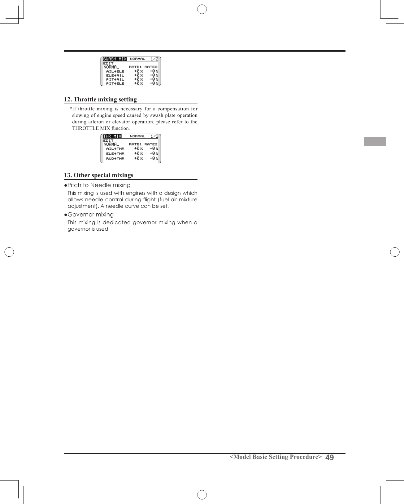
![78 <Functions of Linkage Menu>● Select the function name and return to the Linkage menu by touching the RTN button. Or the HOME/EXIT button is pushed.<SensorTouch™>RETURNSUB-TRIM Setting of neutral position of each servo.(The display screen is an example. The screen depends on the model type.)The Sub-Trim function is used to set the servo neutral position, and may be used to make fine adjustments to the control surface after linkages and pushrods are hooked up. When you begin to set up a model, be sure that the digital trims are set to their center position.Sub-trim adjustment1. Move the cursor to the channel you want to adjust and touch the RTN button to switch to the data input mode.2. Adjust the rate by scrolling the touch sensor. Initial value: 0 Adjustment range: -240~+240 (steps)(When the RTN button is touched for one second, sub-trim is reset to the initial value.)*Before sub-trim adjustment, it is very important to adjust the linkages at the control surface so that you do not use sub-trim, except for very minute adjustments.3. Touch the RTN button to end adjustment and return to the cursor mode.4. Repeat this procedure for each channel.● Select [SUB-TRIM] in the Linkage menu and access the setup screen shown below by touching the RTN button.Scrolling● Moving cursor● Adjusting value](https://usermanual.wiki/Futaba/T14SG-24G.User-Manual-2/User-Guide-1894989-Page-48.png)
![79<Functions of Linkage Menu>● Select the function name and return to the Linkage menu by touching the RTN button. Or the HOME/EXIT button is pushed.<SensorTouch™>RETURNREVERSE Use to reverse the throw direction.Servo Reverse changes the direction of an individual servo’s response to a control input.For CCPM helicopters, be sure to read the section on Swash AFR before reversing any servos. With CCPM helicopters, always complete your servo reversing prior to any other programming. If you use pre-built Airplane/Sailplane functions that control multiple servos, it may be confusing Servo reversing procedure*Upon setup completion of a new model, check whether or not each servo is connected to the correct channel.*Next, determine whether you need to reverse any channels by moving each stick and/or other control inputs.1. Move the cursor to the channel you want to reverse and touch the RTN button to switch to the data input mode.2. Select the direction by scrolling the touch sensor. A conrmation message appears. [NORM]: Normal [REV]: Reverse3. Touch the RTN button to change the direction. (To terminate input and return to the original state, touch the S1 button.)*Repeat the operation above for each channel that must be reversed.to tell whether the servo needs to be reversed or a setting in the function needs to be reversed. See the instructions for each specialized function for further details. Always check servo direction prior to every ight as an additional precaution to conrm proper model memory, hook ups, and radio function.(The display screen is an example. The screen depends on the model type.)● Select [REVERSE] in the Linkage menu and access the setup screen shown below by touching the RTN button.Scrolling● Moving cursor● Selecting mode](https://usermanual.wiki/Futaba/T14SG-24G.User-Manual-2/User-Guide-1894989-Page-49.png)
![80 <Functions of Linkage Menu>● Select the function name and return to the Linkage menu by touching the RTN button. Or the HOME/EXIT button is pushed.<SensorTouch™>RETURNFAIL SAFE Sets the servos operating position when transmitter signals can no longer be received or when the receiver battery voltage drops.(The display screen is an example. The screen depends on the model type.)The Failsafe function may be used to set up positions that the servos move to in the case of radio interference.You may set either of two positions for each channel: Hold, where the servo maintains its last commanded position, or Failsafe, where each servo moves to a predetermined position. You may choose either mode for each channel. (FASST 7CH mode: CH3 only)The T14SG system also provides you with an advanced battery monitoring function that warns you when the receiver battery has only a little power remaining. In this case, each servo is moved to the defined failsafe position. (FASST 7CH mode: CH3 only) The battery failsafe may be released by operating a predefined control on the transmitter (default is throttle), do not continue to fly, land as soon as possible. Remember, if the Fail safe setting procedure1. Move the cursor to the "F/S" item of the channel you want to set and touch the RTN button to switch to the data input mode.2. Select the F/S mode by scrolling the touch sensor. A conrmation message appears. *The display blinks.3. Touch the RTN button. (Touch the S1 button to stop setting.)*The channel switches to the F/S mode.4. Move the cursor to the "POS" item. Hold the corresponding stick, knob, slider, etc. in the position you want the servo to move to when the fail safe function is activated and Touch the RTN button for one second.*The set position is displayed in percentage.*If you want to return that channel to the hold mode, move the cursor to the "F/S" item and touch the RTN button to switch to the data input mode. Select the F/S mode by scrolling the touch sensor. A conrmation message appears and then change the mode by touching the RTN button.predefined control suddenly moves to a position you did not command, land at once and check your receiver battery.Denes servo position when signals are lost and when receiver battery voltage becomes low.Warning For safety, always set the fail safe functions.●Remember to set the throttle channel fail safe function so that the servo moves to the maximum slow side for airplanes and to the slow side from the hovering position for helicopters.Crashing of the model at full high when normal radio waves cannot be received due to interference, etc., is very dangerous.●If the battery fail safe is reset by the throttle stick, it may be mistaken for an engine malfunction and will be reset at throttle slow and the model will continue to y. If you have any doubts, immediately land.Battery fail safe setting procedure Battery fail safe can be set for each channel by the same method as the fail safe setting procedure. Select and set the "B.F/S" item. [ON]: Battery fail safe function ON [OFF]: Battery fail safe function OFFBattery fail safe release switch setting This function temporarily releases the battery fail safe function, so the fuselage can recover after the battery fail safe function was activated by a drop in the receiver battery voltage. This setting selects the switch which releases the battery fail safe function.1. Move the cursor to the [RELEASE B.F/S] item in the setup screen (last page).2. Touch the RTN button.*The switch selection screen is called.*For a detailed description of the switch selection and ON/OFF direction setting method, see [Switch Setting Method] at the back of this manual.● Select [FAIL SAFE] in the Linkage menu and access the setup screen shown below by touching the RTN button.Scrolling● Moving cursor● Selecting mode● Adjusting value● To next page](https://usermanual.wiki/Futaba/T14SG-24G.User-Manual-2/User-Guide-1894989-Page-50.png)