Futaba T14SG-24G Radio Control User Manual 3
Futaba Corporation Radio Control 3
UserManual.wiki
>
Futaba
>
T14SG-24G User Manual
>
User Manual 3
Contents
1.
User Manual 1
2.
User Manual 2
3.
User Manual 3
User Manual 3
Navigation menu
Upload a User Manual
Namespaces
Wiki Guide
HTML
PDF
Info
Views
User Manual
Discussion / Help
Navigation
![81<Functions of Linkage Menu>● Select the function name and return to the Linkage menu by touching the RTN button. Or the HOME/EXIT button is pushed.<SensorTouch™>RETURNEND POINT Sets the travel and limit point of each servo.The End Point function adjusts the left and right servo throws, generates differential throws, and will correct improper linkage settings. The travel rate can be varied from 0% to 140% in each direction on channels 1 to 12(FASSTest 12CH mode). Also, the limit point where servo throw stops may be varied from 0% to 155%.Servo travel adjustment1. Move the cursor to the travel icon of the channel you want to adjust and touch the RTN button to switch to the data input mode.2. Ajust the rate by scrolling the touch sensor. Initial value: 100% Adjustment range: 0%~140%*When the RTN button is touched for one second, the rate is reset to the initial value. Touch the RTN button to end adjustment and return to the cursor mode.3. Repeat this procedure for each rate.Limit point adjustment1. Move the cursor to the limit point icon of the channel you want to adjust and touch the RTN button to switch to the data input mode.2. Ajust the limit point by scrolling the touch sensor. Initial value: 135% Adjustment range: 0%~155%*When the RTN button is touched for one second, the limit point is reset to the initial value. Touch the RTN button to end adjustment and return to the cursor mode.3. Repeat this procedure for each limit point.● Select [END POINT] in the Linkage menu and access the setup screen shown below by touching the RTN button.(The display screen is an example. The screen depends on the model type.)Scrolling● Moving cursor● Adjusting value● To next page(limit point)(travel)(limit point)(travel)](https://usermanual.wiki/Futaba/T14SG-24G.User-Manual-3/User-Guide-1894990-Page-1.png)
![82 <Functions of Linkage Menu>● Select the function name and return to the Linkage menu by touching the RTN button. Or the HOME/EXIT button is pushed.<SensorTouch™>RETURNSERVO SPEED Sets the speed of each servo.The speed of the servo from 1CH to 12CH of operation can be set up. It can adjust to 0-27. Speed becomes slow as a numerical value's 0 increases in the state of the fastest of the servo.* Speed cannot be made quicker than the maximal rate of the servo to be used. Servo speed setting1. Touch the Speed button of the channel you want to set.2. Use the adjustment buttons to adjust the servo speed.●Initial value: 0●Adjustment range: 0~27 (steps)*When the RTN button is touched for one second, the rate is reset to the initial value.3. Repeat this procedure for each channel.* It will overlap, if speed control of a S.BUS servo setup is used at the time of S.BUS servo use, and speed changes. Please use one either. * The speed of THR is not set up simultaneously with THR DELAY (model menu : only airplane).● Select [SERVO SPEED] in the Linkage menu and access the setup screen shown below by touching the RTN button.(The display screen is an example. The screen depends on the model type.)Scrolling● Moving cursor● Adjusting value● To next page(channel)(speed)(speed)(channel)](https://usermanual.wiki/Futaba/T14SG-24G.User-Manual-3/User-Guide-1894990-Page-2.png)
![83<Functions of Linkage Menu>● Select the function name and return to the Linkage menu by touching the RTN button. Or the HOME/EXIT button is pushed.<SensorTouch™>RETURNTHR CUT Stops the engine safely and easily.(airplane and helicopter only)Throttle cut provides an easy way to stop the engine. Generally speaking, modelers will do so by ipping a switch with the throttle stick at idle. The action is not functional at high throttle to avoid accidental dead stick landings. The switch’s location and direction must be chosen, as it defaults to NULL.Individually adjust the Throttle Cut activation setting for each condition. (helicopter)Throttle cut setting procedure1. Activate the function: Move the cursor to the [ACT] item and touch the RTN button to switch to the data input mode. Select the ACT mode by scrolling the touch sensor. *The display blinks. Touch the RTN button to activate the function and return to the cursor mode.2. Switch selection: Move the cursor to the [SW] item and access the switch setup screen by touching the RTN button and select the switch and ON direction.*For a detailed description of the setting method, see [Switch Setting Method] at the back of this manual.3. Throttle cut position setting: Move the cursor to the [POS] item and touch the RTN button to switch to the data input mode. Adjust the servo operation position at throttle cut operation by scrolling the touch sensor. Initial value: 17% Adjustment range: 0%~50%*When the RTN button is touched for one second, the servo operation position is reset to the initial value.) Touch the RTN button to end the adjustment and return to the cursor mode.*With the selected cut switch ON and the throttle stick at idle; adjust the rate until the engine consistently cuts off. However, be sure that the throttle linkage is not pulled too tight or unreasonable force is not applied to the servo.Designating a Throttle Cut setting position. (helicopter)*A throttle cut function acts in the low side of the throttle position.*"THRO" setting is common with all condition.Warning Normal setting is slightly above idle.1. To add the Throttle Cut position, use the cursor to select the THRO percentage desired, then press and hold the RTN button for one second.*Since conditions are not offered when an Airplane is selected, the Throttle Cut options will vary from the options noted below.*The Throttle Cut POS and SW settings are utilized for all conditions.*If the Throttle Cut switch is activated, or on, this status will continue even if the condition is changed to an inhibited setting.*If the condition is inhibited (INH) the Throttle Cut is off if the SW is in the off position and the throttle stick is low.● Select [THR CUT] in the Linkage menu and access the setup screen shown below by touching the RTN button.● Current throttle position● Individually adjust the Throttle Cut activation setting for each condition. (helicopter)● Cut positionScrolling● Moving cursor● Selecting mode● Adjusting value● Throttle cut status● Throttle cut status● Throttle stick position](https://usermanual.wiki/Futaba/T14SG-24G.User-Manual-3/User-Guide-1894990-Page-3.png)
![84 <Functions of Linkage Menu>● Select the function name and return to the Linkage menu by touching the RTN button. Or the HOME/EXIT button is pushed.<SensorTouch™>RETURNIDLE DOWN Lowers the engine idling speed.(airplane only)The Idle Down function lowers the engine to its idle position. Like Throttle Cut, this is usually accomplished by ipping a switch with the throttle stick at idle. The action is not functional at high throttle to avoid accidental dead sticks. The switch’s location and direction must be chosen, as it defaults to NULL.Idle down setting procedure1. Activate the function: Move the cursor to the [ACT] item and touch the RTN button to switch to the data input mode. Select the ACT mode by scrolling the touch sensor. *The display blinks. Touch the RTN button to activate the function and return to the cursor mode.2. Switch selection: Move the cursor to the [SW] item and access the switch setup screen by touching the RTN button. Select the switch and ON direction.*For a detailed description of the setting method, see [Switch Setting Method] at the back of this manual.3. Offset rate setting: Move the cursor to the [OFFSET] item and touch the RTN button to switch to the data input mode. Adjust the servo offset rate at idle down operation by scrolling the touch sensor. Initial value: 0% Adjustment range: -100%~0%~+100%* When a minus rate is input, an offset is applied at the high side.*Maximum offset amount is near maximum slow.* When the RTN button is touched for one second, the offset rate is reset to the initial value. Touch the RTN button to end the adjustment and return to the cursor mode.● Select [IDLE DOWN] in the Linkage menu and access the setup screen shown below by touching the RTN button.Scrolling● Moving cursor● Selecting mode● Adjusting value● Current throttle position](https://usermanual.wiki/Futaba/T14SG-24G.User-Manual-3/User-Guide-1894990-Page-4.png)
![85<Functions of Linkage Menu>● Select the function name and return to the Linkage menu by touching the RTN button. Or the HOME/EXIT button is pushed.<SensorTouch™>RETURNSWASH RINGSwash ring setting procedure1. Activate the function: Move the cursor to the [ACT] item and touch the RTN button to switch to the data input mode. Select the ACT mode by scrolling the touch sensor. *The display blinks. Touch the RTN button to activate the function and return to the cursor mode.2. Rate setting: Move the cursor to the [RATE] item touch the RTN button to switch to the data input mode. Set the rate by scrolling the touch sensor. Initial value: 100%. Adjustment range: 50 to 200%.*Adjust the rate to maximum swash tilt. *When the RTN button is touched for one second, the rate is reset to the initial value. Touch the RTN button to end adjustment and return to the cursor mode.Limits the swash plate travel to within a xed range. (Helicopter only)This function limits the swash travel to a fixed range in order to prevent damaging the swash linkage by simultaneous operation of the ailerons and elevators. It is very useful in 3D aerobatics which use a large travel.● The operating range display area: The vertical direction shows the elevator travel. The horizontal direction shows the aileron travel.● The marker shows the stick position.● Select [SWASH RING] in the Linkage menu and access the setup screen shown below by touching the RTN button.● When the swash ring function is activated, a circle is displayed in the operating range display area and the rate input box is displayed. Stick operation is limited to the area of this circle.Scrolling● Moving cursor● Selecting mode● Adjusting value](https://usermanual.wiki/Futaba/T14SG-24G.User-Manual-3/User-Guide-1894990-Page-5.png)
![86 <Functions of Linkage Menu>● Select the function name and return to the Linkage menu by touching the RTN button. Or the HOME/EXIT button is pushed.<SensorTouch™>RETURNSWASH Swash AFR and linkage correction function. (helicopter only, except swash type H-1)Neutral PointAt your linkages, if the servo horn deviates from a perpendicular position at neutral, the linkage compensation functions in this menu may not compensate effectively. To correct this use the Neutral Point function. This will move the neutral point of the servos to the actual perpendicular position. However, this adjustment changes only the axis point of the compensation functions in this menu, and does not affect the neutral position of other functions.Swash AFRSwash AFR function reduces, increases, or reverses the rate (travel) of the aileron, elevator and collective pitch functions, by adjusting or reversing the motion of all servos involved in that function, only when using that function. Mixing RateThis mixing is used to compensate the swash-plate as necessary during specific control inputs. Neutral point setting procedureThe neutral point becomes the correction standard point.*Adjusting the servo horn so that the neutral point is near the 50% position makes the mixing amount small.1. Neutral point setting Move the cursor to the [POS] item and hold the pitch operation so that the servo horn is at a right angle to the linkage rod and Touch the RTN button for one second. This value indicates the servo's neutral position. After reading the neutral point, use the other correction functions to make further adjustments.The following compensation mixing is possible; PIT to AIL, PIT to ELE, AIL to PIT, ELE to AIL, and ELE to PIT (HR3 mode.) It adjusts the swash-plate to for proper operation of each control using the corresponding compensation mixing.Linkage CompensationThis compensation mixing is used to correct the swash-plate for pitch control at low pitch and high pitch.Speed CompensationThis function is used to cancel the reaction that is generated by the difference in the movements of each servo when the swash-plate moves.SubtrimSubtrim for aileron, elevator and pitch can be set during swash setting.Pitch adjustment functionHigh, neutral and low pitch xed outputs can be used while adjusting the pitch.Swash AFR setting procedureThe swash AFR function makes adjustments so that the servos travel the specied amount by [AIL], [ELE], and [PIT] operation.1. Move the cursor to the function you want to adjust and touch the RTN button to switch to the data input mode.2. Adjust the AFR rate by scrolling the touch sensor. Initial value: +50% Adjustment range: -100%~+100%*When the RTN button is touched for one second, the AFR rate is reset to the initial value. Touch the RTN button to end adjustment and return to the cursor mode.● Select [SWASH] in the Linkage menu and access the setup screen shown below by touching the RTN button.Scrolling● Moving cursor● Selecting mode● Adjusting value● To next page](https://usermanual.wiki/Futaba/T14SG-24G.User-Manual-3/User-Guide-1894990-Page-6.png)
![87<Functions of Linkage Menu>Mixing rate setting procedureThe HR3 swash-plate type will be used as an example to describe mixing rate setting. The mixing used in other swash modes may be different, however, the setting procedure is the same.*Set the throttle stick to the preset neutral point. Adjust the length of the linkage rod so that the swash plate is horizontal at this position.*The sub-trim function can be used to make small adjustments.*Adjust so that the pitch curve is a straight line and the helicopter achieves maximum pitch.*Move the cursor to the item you want to adjust and touch the RTN button to switch to the data input mode. Touch the RTN button to end adjustment and return to the cursor mode.1. Adjusting the aileron operation [AIL to PIT] Adjust the AIL to PIT rate so there is no binding in the elevator or pitch movement when the aileron stick is moved to the left and right.*Adjust by scrolling the touch sensor.*The left and right sides can be adjusted individually.2. Adjusting the elevator operation [ELE to AIL]/[ELE to PIT] Adjust the ELE to AIL and ELE to PIT rates so there is no binding in the aileron or pitch movement when the elevator stick is moved up and down.*Adjust by scrolling the touch sensor.*The up and down sides can be adjusted individually.3. Adjusting the pitch operation [PIT to AIL][PIT to ELE] Adjust the PIT to AIL and PIT to ELE rates so that the swash plate moves to the level/horizontal position when the throttle stick was moved to maximum low and full high.*Adjust by scrolling the touch sensor.*The slow and high sides can be adjusted individually.Linkage compensation setting procedure*Prior to utilizing the linkage compensation settings, it is important to adjust the mixing rate settings.*Linkage compensation overrides interference from the aileron operation with the elevator or elevator operation with the aileron at collective pitch control for low pitch and high pitch.*When making the following setting, Move the cursor to the item you want to set and touch the RTN button to switch to the data input mode. Touch the RTN button to end adjustment and return to the cursor mode.1. Compensating aileron input [AIL] Set the throttle to the lowest position. Move the aileron stick to the left and right and adjust the aileron compensation amount so that interference in the elevator or pitch direction is minimal.*Adjust by scrolling the touch sensor.*The left and right sides can be adjusted individually.*If the interference increases when the compensation amount was increased, make adjustments with the direction [DIR.] using the plus "+" or minus "-".2. Compensating elevator input [ELE] Adjust the elevator compensation amount so that the aileron or pitch direction interference when the elevator stick was moved up and down is minimal.3. Repeat steps 1 and 2 above, perform aileron and elevator compensation similarly at full throttle.Speed compensation setting procedure1. Move the cursor to the "SPEED" item and touch the RTN button to switch to the data input mode.2. Set the throttle stick to the neutral point position. Quickly move the elevator stick and adjust the speed compensation amount [SPEED] for minimum interference in the pitch direction.*Adjust by scrolling the touch sensor. Touch the RTN button to end adjustment and return to the cursor mode.](https://usermanual.wiki/Futaba/T14SG-24G.User-Manual-3/User-Guide-1894990-Page-7.png)
![89<Functions of Linkage Menu>● Select the function name and return to the Linkage menu by touching the RTN button. Or the HOME/EXIT button is pushed.<SensorTouch™>RETURNT1-T4 SET. Digital trim settingsThis function adjusts the digital trim's step amount and operation mode (T1~T4.)When the flight conditions are set, the trim operation can be coupled with the conditions when combination mode is selected.The T14SG unit of trim is displayed on the home screen.Control step amount setting1. Move the cursor to the [STEP] item and touch the RTN button to switch to the data input mode. 2. Set the control step amount by scrolling the touch sensor. Initial value: 4 Adjustment range: 0~200*When the RTN button is touched for one second, the control step amount is reset to the initial value.*When the value is increased, the change per step becomes larger.3. Touch the RTN button to end adjustment and return to the cursor mode.Separate/combination mode selection (Heli and Glider only)1. Move the cursor to the [MODE] item and touch the RTN button to switch to the data input mode.2. Select the mode by scrolling the touch sensor. A conrmation message appears. *The display blinks. [COMB.]: Combination mode. The trim's data is reected in all ight conditions. [SEPAR]: Separate mode. Trim adjustments are made individually for each flight condition.3. Touch the RTN button. (To terminate the input and return to the original state, touch the S1 button.)Display unit selection1. Move the cursor to the [UNIT] item and touch the RTN button to switch to the data input mode.2. Select the mode by scrolling the touch sensor. A conrmation message appears. *The display blinks. [--]: A step number is displayed on the home screen. There is no unit display. [ %]: "%" is displayed as a unit.3. Touch the RTN button. (To terminate the input and return to the original state, touch the S1 button.)Trim Memory Operation procedure1. Move the cursor to the [T1-T4 MEMORY] item and touch the RTN button to switch to the data input mode.2. Select the ACT mode by scrolling the touch sensor. A conrmation message appears. [INH]: Inhibited [ACT]: Activated3. Touch the RTN button. (To terminate the input and return to the original state, touch the S1 button.)4. At the home screen, move the cursor to the trim you want to change and touch the RTN for one second. The trim display is moved to the center position.*When the function is inhibited, the trim position returns to the actual trim position.Only the trim displayed on the home screen can be moved to the center position without changing the actual trim's memory position. ● Select [T1-T4 SET.] in the Linkage menu and access the setup screen shown below by touching the RTN button.(The display screen is an example. The screen depends on the model type.)● Trim operation mode"COMB.": Combination mode"SEPAR": Separate modeScrolling● Moving cursor● Selecting mode● Adjusting value● To next page*The display blinks.](https://usermanual.wiki/Futaba/T14SG-24G.User-Manual-3/User-Guide-1894990-Page-9.png)
![90 <Functions of Linkage Menu>● Select the function name and return to the Linkage menu by touching the RTN button. Or the HOME/EXIT button is pushed.<SensorTouch™>RETURNWARNING Low Battery alarm voltage set Warning normal reset The T14SG includes an audible alarm that sounds when the transmitter’s battery voltage drops below a pre-determined setting; adjustable for cell types and voltages.Mixing warning at power ON can be reset to OFF.Accessing and Activating the Low Battery Alarm1. The Low Battery (LOW BATTERY) alarm voltage is accessed through the T14SG’s System Menu. Within the System Menu, use the SensorTouch™ to highlight the SOUND option and then press the Return (RTN) button to conrm the selection.2. Use the SensorTouch to scroll to the Low Battery (LOW BATTERY) alarm, and then press the Return (RTN) button to access the voltage settings. Using the SensorTouch, adjust the voltage as desired and/or determined by the transmitter battery pack being utilized. The voltage options range from 5.0V to 6.0V. Suggested voltage settings are as follows:5-Cell NiCd or NiMH: 5.6V2-Cell LiFe: 6.0V Warning normally resetting method1. Move the cursor to the item you want to reset to OFF and touch the RTN button to switch to the data input mode. 2. Select the OFF mode by scrolling the touch sensor. *The display blinks.3. Touch the RTN button. (To terminate the input and return to the original state, touch the S1 button.)Warning display:Airplane: Throttle cut/Idle down/Throttle position/Snap-roll/Motor position/Airbrake/MotorHelicopter: Condition/Throttle cut/Throttle position/Throttle HoldGlider: Condition/Motor position/Trim-mix/Motor● Select [WARNING] in the Linkage menu and access the setup screen shown below by touching the RTN button.● Push S1 button to advance to next page.Scrolling● Moving cursor● Selecting mode● Adjusting value● To next page*About low battery voltage, all the models included in one transmitter are changed in common. It cannot set to different voltage for every model. Moreover, data reset is not carried out.](https://usermanual.wiki/Futaba/T14SG-24G.User-Manual-3/User-Guide-1894990-Page-10.png)
![91<Functions of Linkage Menu>● Select the function name and return to the Linkage menu by touching the RTN button. Or the HOME/EXIT button is pushed.<SensorTouch™>RETURNTELEMETRY Displaying data from the receiver This screen displays your choice of data from the receiver.Also warnings can be activated regarding other data from your aircraft. For example, if the receiver voltage drops, the user can be warned by an alarm (and vibration).*It cannot be used in FASST mode and S-FHSS mode.*Only receiver voltage and EXT voltage can be used in FASSTest12CH mode.*The FASSTest14CH mode can use all the telemetry functions. ● Select [TELEMETRY] in the Linkage menu and access the setup screen shown below by touching the RTN button.● Push S1 button to advance to next page.● [TELEMETRY] can be called if the HOME/EXIT button is pushed from a home screen.Scrolling● Moving cursor● Selecting mode● Adjusting value● To next page● Receiver -> Transmitter. The reception strength is shown.How to see telemetry date1. Telemetry screen can be called if the HOME/EXIT button is pushed from the home screen. Or select [TELEMETRY] in the Linkage menu and access the setup screen by touching the RTN button. 2. If each item is chosen and the RTN button is pushed, an alarm setup can be performed with the minimum/maximum after a transmitter is turned on. *Receiver voltage can be checked immediately. An optional sensor will need to be attached to S.BUS2 of a receiver if you would like to see other information. *No special setup is necessary if each sensor displayed is left as in the default setup. Separate sensor ID is also unnecessary. However, if two or more of one kind of sensor is used, setup is required in the "SENSOR" menu.Warning Do not watch the transmitter screen during ight.*You may loose sight of the aircraft during ight and this is extremely dangerous. Have an assistant on hand to check the screen for you. A pilot should NEVER take his eyes off his aircraft.](https://usermanual.wiki/Futaba/T14SG-24G.User-Manual-3/User-Guide-1894990-Page-11.png)
![92 <Functions of Linkage Menu>● Select the function name and return to the Linkage menu by touching the RTN button. Or the HOME/EXIT button is pushed.<SensorTouch™>RETURNTELEMETRY : Rx-BATT. Displaying data from the receiver battery voltageIn this screen, the battery voltage of a receiver is displayed.If it becomes higher or lower than the setting an alarm and/or vibration will alert you.*It cannot be used in FASST mode and S-FHSS mode.*Only receiver voltage and EXT voltage can be used in FASSTest12CH mode.*The FASSTest14CH mode can use all the telemetry functions.● Select [Rx-BATT.] in the TELEMETRY screen and access the setup screen shown below by touching the RTN button.Scrolling● Moving cursor● Selecting mode● Adjusting value● To next page● Receiver battery voltage ● The maximum and the minimum when powering ON are shown.● ↓The "down" arrow will indicate that an alarm will sound when the voltage drops to below the setting.Alert set 1. Move the cursor to the ↓ALERT [INH] item and touch the RTN button to switch to the data input mode. 2. Select the ACT mode by scrolling the touch sensor. 3. Touch the RTN button. (To terminate the input and return to the original state, touch the S1 button.) 4. Move the cursor to the ↓THRESHOLD [4.0V] item and touch the RTN button to switch to the data input mode. 5. Ajust the rate by scrolling the touch sensor. Initial value: 4.0V Adjustment range: 0.0V~8.4V*When the RTN button is touched for one second, the rate is reset to the initial value.6. Touch the RTN button. (To terminate the input and return to the original state, touch the S1 button.)TYPE 1TYPE 2TYPE 3TYPE 4"Vibes" typeIf the following types are selected, the transmitter will vibrate during the warning.](https://usermanual.wiki/Futaba/T14SG-24G.User-Manual-3/User-Guide-1894990-Page-12.png)
![93<Functions of Linkage Menu>● Select the function name and return to the Linkage menu by touching the RTN button. Or the HOME/EXIT button is pushed.<SensorTouch™>RETURNTELEMETRY : EXT-VOLT Displaying data from the EXT battery voltage portThe EXT-VOLT screen will display the data from the EXT-battery output from the R7008SB receiver. In order to use this function, it is necessary to connect External voltage connector of the R7008SB receiver to a CA-RVIN-700 (FUTM5551) or SBS-01V to the battery you desire to measure the voltage of.You will be alerted by an alarm or vibration if the voltage set by you is exceeded.*It cannot be used in FASST mode and S-FHSS mode.*Only receiver voltage and EXT voltage will be received in the FASSTest12CH mode.*The FASSTest14CH mode will display all telemetry data.● Select [EXT-VOLT] in the TELEMETRY screen and access the setup screen shown below by touching the RTN button.Scrolling● Moving cursor● Selecting mode● Adjusting value● To next page● EXT battery voltage ● The maximum and the minimum when powering ON are shown. ● ↓The arrow will indicate that an alarm will sound when the voltage drops to below the setting.Alert set 1. Move the cursor to the ↓ALERT [INH] item and touch the RTN button to switch to the data input mode. 2. Select the ACT mode by scrolling the touch sensor. 3. Touch the RTN button. (To terminate the input and return to the original state, touch the S1 button.) 4. Move the cursor to the ↓THRESHOLD [4.0V] item and touch the RTN button to switch to the data input mode. 5. Ajust the rate by scrolling the touch sensor. Initial value: 4.0V Adjustment range: 0.0V~100.0V*When the RTN button is touched for one second, the rate is reset to the initial value.6. Touch the RTN button. (To terminate the input and return to the original state, touch the S1 button.)TYPE 1TYPE 2TYPE 3TYPE 4"Vibes" typeIf the following types are selected, the transmitter will vibrate during the warning.*CA-RVIN-700 or SBS-01V must be installed in the aircraft.](https://usermanual.wiki/Futaba/T14SG-24G.User-Manual-3/User-Guide-1894990-Page-13.png)
![94 <Functions of Linkage Menu>● Select the function name and return to the Linkage menu by touching the RTN button. Or the HOME/EXIT button is pushed.<SensorTouch™>RETURNTELEMETRY : TEMP. Displaying data from the temperatureTEMP. is a screen which displays/sets up the temperature information from an optional temperature sensor. The temperature of the model (engine, motor, battery etc.) which is ying can be displayed.If it becomes higher or lower than the setting an alarm and/or vibration will alert you.*It cannot be used in FASST mode and S-FHSS mode.*Only receiver voltage and EXT voltage can be used inFASSTest12CH mode.*The FASSTest14CH mode can use all the telemetry functions.● Select [TEMP.] in the TELEMETRY screen and access the setup screen shown below by touching the RTN button.●Press the S1 button to advance to the next page.Scrolling● Moving cursor● Selecting mode● Adjusting value● To next page● Temperature● The maximum and the minimum when powering ON are shown. ● ↓ An downward arrow will show that an alarm will sound when the temperature drops below the set value.● ↑ An upward arrow will show that an alarm will sound when the temperature rises above the set value.Alert set : Hot warning 1. Move the cursor to the ↑ALERT item and touch the RTN button to switch to the data input mode. 2. Select the ACT mode by scrolling the touch sensor. 3. Touch the RTN button. (To terminate the input and return to the original state, touch the S1 button.) 4. Move the cursor to the ↑THRESHOLD [+100℃]item and touch the RTN button to switch to the data input mode. 5. Ajust the rate by scrolling the touch sensor. Initial value: +100℃ Adjustment range: 1℃~200℃(↑THRESHOLD > ↓THRESHOLD)*When the RTN button is touched for one second, the rate is reset to the initial value.6. Touch the RTN button. (To terminate the input and return to the original state, touch the S1 button.)Alert set : Low-temperature warning1. 2/2 page is accessed by pushing S1. Move the cursor to the ↓ALERT item and touch the RTN button to switch to the data input mode. 2. Select the ACT mode by scrolling the touch sensor. 3. Touch the RTN button. (To terminate the input and return to the original state, touch the S1 button.) 4. Move the cursor to the ↓THRESHOLD [+0 ℃]item and touch the RTN button to switch to the data input mode. 5. Ajust the rate by scrolling the touch sensor. Initial value: +0℃ Adjustment range: 0℃~199℃(↑THRESHOLD > ↓THRESHOLD)*When the RTN button is touched for one second, the rate is reset to the initial value.6. Touch the RTN button. (To terminate the input and return to the original state, touch the S1 button.)TYPE 1TYPE 2TYPE 3TYPE 4"Vibes" typeIf the following types are selected, the transmitter will vibrate during the warning.*A temperature sensor must be installed in the aircraft.](https://usermanual.wiki/Futaba/T14SG-24G.User-Manual-3/User-Guide-1894990-Page-14.png)
![95<Functions of Linkage Menu>● Select the function name and return to the Linkage menu by touching the RTN button. Or the HOME/EXIT button is pushed.<SensorTouch™>RETURNTELEMETRY : RPM Displaying data from the RPMRPM is a screen which displays / sets up the RPM information from an optional RPM sensor. The RPM of the model (engine, motor, etc.) which is ying can be shown.If it becomes higher or lower than the setting an alarm and/or vibration will alert you. *It cannot be used in FASST mode and S-FHSS mode.*Only receiver voltage and EXT voltage can be used inFASSTest12CH mode.*The FASSTest14CH mode can use all the telemetry functions.● Select [RPM] in the TELEMETRY screen and access the setup screen shown below by touching the RTN button.●Press the S1 button to advance to the next page.Scrolling● Moving cursor● Selecting mode● Adjusting value● To next page● RPM● The maximum and the minimum when powering ON are shown.●"MAGNETIC" or "OPTICAL" is set according to the sensor you use.SBS-01RM : MAGNETICSBS-01RO : OPTICAL● ↓An downward arrow indicates that the alarm will sound when the RPM falls below the set value.● ↑An upward arrow indicates that the alarm will sound when the RPM rises above the set value.Alert set : Over rotations 1. Move the cursor to the ↑ALERT item and touch the RTN button to switch to the data input mode. 2. Select the ACT mode by scrolling the touch sensor. 3. Touch the RTN button. (To terminate the input and return to the original state, touch the S1 button.) 4. Move the cursor to the ↑THRESHOLD [2000rpm]item and touch the RTN button to switch to the data input mode. 5. Ajust the rate by scrolling the touch sensor. Initial value: 2000rpm Adjustment range: 1rpm~150,000rpm(↑THRESHOLD > ↓THRESHOLD)*When the RTN button is touched for one second, the rate is reset to the initial value.6. Touch the RTN button. (To terminate the input and return to the original state, touch the S1 button.)Alert set : Under rotations1. Scroll to the second page by pushing S1. Move the cursor to the ↓ALERT item and touch the RTN button to switch to the data input mode. 2. Select the ACT mode by scrolling the touch sensor. 3. Touch the RTN button. (To terminate the input and return to the original state, touch the S1 button.) 4. Move the cursor to the ↓THRESHOLD [0rpm]item and touch the RTN button to switch to the data input mode. 5. Ajust the rate by scrolling the touch sensor. Initial value: 0rpm Adjustment range: 0rpm~149,999rpm(↑THRESHOLD > ↓THRESHOLD)*When the RTN button is touched for one second, the rate is reset to the initial value.6. Touch the RTN button. (To terminate the input and return to the original state, touch the S1 button.)TYPE 1TYPE 2TYPE 3TYPE 4"Vibes" typeIf the following types are selected, the transmitter will vibrate during the warning.● In "MAGNETIC", the gear ratio of your engine (motor) you are using is entered. ● In "OPTICAL", the number of blades of the propeller ( r o t o r ) your model is entered. *A RPM sensor must be installed in the aircraft.](https://usermanual.wiki/Futaba/T14SG-24G.User-Manual-3/User-Guide-1894990-Page-15.png)
![96 <Functions of Linkage Menu>● Select the function name and return to the Linkage menu by touching the RTN button. Or the HOME/EXIT button is pushed.<SensorTouch™>RETURNTELEMETRY : ALTITUDE Displaying data from the altitudeALTITUDE is a screen which displays / sets up the altitude information from an optional altitude sensor or GPS sensor. The altitude of the model which is ying can be known. If it becomes higher (low) than preset altitude, you can be told by alarm. To show warning by vibration can also be chosen. Data when a power supply is turned on shall be 0 m, and it displays the altitude which changed from there. Even if the altitude of an aireld is high, that shall be 0 m and the altitude difference from an airfield is displayed. This sensor calculates the altitude from atmospheric pressure. Atmospheric pressure will get lower as you go up in altitude, using this the sensor will estimate the altitude. Please understand that an exact advanced display cannot be performed if atmospheric pressure changes in a weather situation.*It cannot be used in FASST mode and S-FHSS mode.*Only receiver voltage and EXT voltage can be used in FASSTest12CH mode.*The FASSTest14CH mode can use all the telemetry functions.● Select [ALTITUDE] in the TELEMETRY screen and access the setup screen shown below by touching the RTN button.Scrolling● Moving cursor● Selecting mode● Adjusting value● To next page● Altitude● The maximum and the minimum when powering ON are shown.● ↓ An downward arrow indicates the alarm will sound when the altitude reaches below your set value.● ↑ An upward arrow indicates the alarm will sound when the altitude reaches above your set value.First, the set of a reference is required.1. The model and transmitter to which the altitude sensor was connected are turned on. 2. Move the cursor to the [SET] of "REFERENCE" item and touch the RTN button to switch to the data input mode. 3. Touch the RTN button. (To terminate the input and return to the original state, touch the S1 button.) *Atmospheric pressure is changed according to the weather also at the same aireld. You should preset before a ight.Alert set : High side 1. Move the cursor to the ↑ALERT item and touch the RTN button to switch to the data input mode. 2. Select the ACT mode by scrolling the touch sensor. 3. Touch the RTN button. (To terminate the input and return to the original state, touch the S1 button.) 4. Move the cursor to the ↑THRESHOLD [+200m]item and touch the RTN button to switch to the data input mode. 5. Ajust the rate by scrolling the touch sensor. Initial value: +200m Adjustment range: -499m~+5,000m(↑THRESHOLD > ↓THRESHOLD)*When the RTN button is touched for one second, the rate is reset to the initial value.6. Touch the RTN button. (To terminate the input and return to the original state, touch the S1 button.)Alert set : Low side1. Scroll to the second page by pushing S1. Move the cursor to the ↓ALERT item and touch the RTN button to switch to the data input mode. 2. Select the ACT mode by scrolling the touch sensor. 3. Touch the RTN button. (To terminate the input and return to the original state, touch the S1 button.) 4. Move the cursor to the ↓THRESHOLD [-50m]item and touch the RTN button to switch to the data input mode. 5. Ajust the rate by scrolling the touch sensor. Initial value: -50m Adjustment range: -500m~+4,999m(↑THRESHOLD > ↓THRESHOLD)*When the RTN button is touched for one second, the rate is reset to the initial value.6. Touch the RTN button. (To terminate the input and return to the original state, touch the S1 button.)TYPE 1TYPE 2TYPE 3TYPE 4"Vibes" typeIf the following types are selected, the transmitter will vibrate during the warning.*An altitude sensor or GPS sensor must be installed in the aircraft.●Press the S1 button to advance to the next page.](https://usermanual.wiki/Futaba/T14SG-24G.User-Manual-3/User-Guide-1894990-Page-16.png)
![97<Functions of Linkage Menu>● Select the function name and return to the Linkage menu by touching the RTN button. Or the HOME/EXIT button is pushed.<SensorTouch™>RETURNTELEMETRY : VARIO Displaying data from the variometerVARIO is a screen which displays / sets up the variometer information from an optional altitude sensor or GPS sensor. The variometer of the model which is ying can be known.If it becomes higher or lower than the setting an alarm and/or vibration will alert you.To ensure that the pilot is aware as to the model's status, the T14SG incorporates a different melody for ascent and descent. Additionally, depending upon the rate of climb or descent, the tones vary to indicate whether or not the airplane is climbing or descending at a rapid rate. *It cannot be used in FASST mode and S-FHSS mode.*Only receiver voltage and EXT voltage can be used inFASSTest12CH mode.*The FASSTest14CH mode can use all the telemetry functions.● Select [VARIO] in the TELEMETRY screen and access the setup screen shown below by touching the RTN button.Scrolling● Moving cursor● Selecting mode● Adjusting value● To next page● Variometer● The maximum and the minimum when powering ON are shown. ● If this is set to ACT, a melody will be activated during the rise or dive, depending on your set values. ● ↓ An downward arrow indicates the alarm will sound when the altitude reaches below your set value.● ↑ An upward arrow indicates the alarm will sound when the altitude reaches above your set value.Alert set : Rise side 1. Move the cursor to the ↑ALERT item and touch the RTN button to switch to the data input mode. 2. Select the ACT mode by scrolling the touch sensor. 3. Touch the RTN button. (To terminate the input and return to the original state, touch the S1 button.) 4. Move the cursor to the ↑THRESHOLD [+0m/s]item and touch the RTN button to switch to the data input mode. 5. Ajust the rate by scrolling the touch sensor. Initial value: +0m/s Adjustment range: -49m/s~+50m/s(↑THRESHOLD > ↓THRESHOLD)*When the RTN button is touched for one second, the rate is reset to the initial value.6. Touch the RTN button. (To terminate the input and return to the original state, touch the S1 button.)Alert set : Dive side1. Scroll to the second page by pushing S1. Move the cursor to the ↓ALERT item and touch the RTN button to switch to the data input mode. 2. Select the ACT mode by scrolling the touch sensor. 3. Touch the RTN button. (To terminate the input and return to the original state, touch the S1 button.) 4. Move the cursor to the ↓THRESHOLD [+0m/s]item and touch the RTN button to switch to the data input mode. 5. Ajust the rate by scrolling the touch sensor. Initial value: +0m/s Adjustment range: -50m/s~+49m(↑THRESHOLD > ↓THRESHOLD)*When the RTN button is touched for one second, the rate is reset to the initial value.6. Touch the RTN button. (To terminate the input and return to the original state, touch the S1 button.)TYPE 1TYPE 2TYPE 3TYPE 4"Vibes" type*An altitude sensor or GPS sensor must be installed in the aircraft.If the following types are selected, the transmitter will vibrate during the warning.●Press the S1 button to advance to the next page.](https://usermanual.wiki/Futaba/T14SG-24G.User-Manual-3/User-Guide-1894990-Page-17.png)
![98 <Functions of Linkage Menu>● Select the function name and return to the Linkage menu by touching the RTN button. Or the HOME/EXIT button is pushed.<SensorTouch™>RETURNTELEMETRY : BATTERY Displaying data from the battery voltageIn this screen, the battery voltage is displayed. In order to use this function, it is necessary to connect External voltage connector of R7008SB ⇔ SBS-01V ⇔ Battery SBS-01V measures two batteries. The drive battery connected to two lines is displayed on EXT-VOLT. The battery for receivers connected to 3P lines is displayed here. *It cannot be used in FASST mode and S-FHSS mode.*Only receiver voltage and EXT voltage can be used inFASSTest12CH mode.*The FASSTest14CH mode can use all the telemetry functions.● Select [BATTERY] in the TELEMETRY screen and access the setup screen shown below by touching the RTN button.Scrolling● Moving cursor● Selecting mode● Adjusting value● To next page● battery voltage ● The maximum and the minimum when powering ON are shown. ● ↓The arrow will indicate that an alarm will sound when the voltage drops to below the setting.Alert set 1. Move the cursor to the ↓ALERT [INH] item and touch the RTN button to switch to the data input mode. 2. Select the ACT mode by scrolling the touch sensor. 3. Touch the RTN button. (To terminate the input and return to the original state, touch the S1 button.) 4. Move the cursor to the ↓THRESHOLD [4.0V] item and touch the RTN button to switch to the data input mode. 5. Ajust the rate by scrolling the touch sensor. Initial value: 4.0V Adjustment range: 0.0V~8.4V*When the RTN button is touched for one second, the rate is reset to the initial value.6. Touch the RTN button. (To terminate the input and return to the original state, touch the S1 button.)TYPE 1TYPE 2TYPE 3TYPE 4"Vibes" typeIf the following types are selected, the transmitter will vibrate during the warning.*SBS-01V must be installed in the aircraft.](https://usermanual.wiki/Futaba/T14SG-24G.User-Manual-3/User-Guide-1894990-Page-18.png)
![99<Functions of Linkage Menu>● Select the function name and return to the Linkage menu by touching the RTN button. Or the HOME/EXIT button is pushed.<SensorTouch™>RETURNTELEMETRY : DISTANCE Displaying data from the distanceDistance is a screen that displays and sets the altitude data from an SBS-01G (GPS Sensor) sold separately. The distance to the airborne aircraft can be read by the transmitter. When the aircraft ies outside (inside) the set distance the operator is alerted by an alarm and vibration.*The GPS sensor sold separately is necessary. Mount and connect the sensor in accordance with the sensor instruction manual. *It cannot be used in FASST mode and S-FHSS mode.*Only receiver voltage and EXT voltage can be used in FASSTest12CH mode.*The FASSTest14CH mode can use all the telemetry functions.● Select [DISTANCE] in the TELEMETRY screen and access the setup screen shown below by touching the RTN button.Scrolling● Moving cursor● Selecting mode● Adjusting value● To next page●Current distance●Distance alarm setting range 1m ~ 5,000m*Alarm when the aircraft moves far away.(↑THRESHOLD > ↓THRESHOLD)●Distance alarm setting range 0m ~ 4,999m(↑THRESHOLD > ↓THRESHOLD)● Maximum distance after transmitter was turned on. ● The ↓arrow shows that an alarm is generated when the distance drops below the set value.● The ↑arrow shows that an alarm is generated when the set value is exceeded.First, the set of a reference is required.1. The model and transmitter to which the GPS sensor was connected are turned on. 2. It waits until the GPS receiving accuracy displayed on a screen becomes three. 3. Move the cursor to the [SET] of "REFERENCE" item and touch the RTN button to switch to the data input mode. 4. Touch the RTN button. (To terminate the input and return to the original state, touch the S1 button.) *Now, the position of the present model was set to 0 m.Alert setting when aircraft goes too far1. Move the cursor to the ↑ALERT item and touch the RTN button to switch to the data input mode. 2. Select the ACT mode by scrolling the touch sensor. 3. Touch the RTN button. (To terminate the input and return to the original state, touch the S1 button.) 4. Move the cursor to the ↓THRESHOLD [1,000m]item and touch the RTN button to switch to the data input mode. 5. Ajust the rate by scrolling the touch sensor.*When the RTN button is touched for one second, the rate is reset to the initial value.6. Touch the RTN button. (To terminate the input and return to the original state, touch the S1 button.)TYPE 1TYPE 2TYPE 3TYPE 4"Vibes" type*A GPS sensor must be installed in the aircraft.If the following types are selected, the transmitter will vibrate during the warning.●Press the S1 button to advance to the next page.GG●It is the receiving accuracy from a GPS Satellite. Please wait until it becomes 3 displays, and push [REFERENCE].](https://usermanual.wiki/Futaba/T14SG-24G.User-Manual-3/User-Guide-1894990-Page-19.png)
![100 <Functions of Linkage Menu>● Select the function name and return to the Linkage menu by touching the RTN button. Or the HOME/EXIT button is pushed.<SensorTouch™>RETURNGSurfaceAltitudeSlant●Altitude calculated as either straight line distance (slant) or surface distance on a map can also be selected (3/3)Alert setting when the aircraft approaches1. Access the second page by pushing S1. Move the cursor to the ↓ALERT item and touch the RTN button to switch to the data input mode. 2. Select the ACT mode by scrolling the touch sensor. 3. Touch the RTN button. (To terminate the input and return to the original state, touch the S1 button.) 4. Move the cursor to the ↓THRESHOLD [0m]item and touch the RTN button to switch to the data input mode. 5. Ajust the rate by scrolling the touch sensor.*When the RTN button is touched for one second, the rate is reset to the initial value.6. Touch the RTN button. (To terminate the input and return to the original state, touch the S1 button.)Slant and surface distance● Select [DISTANCE] in the TELEMETRY screen by touching the RTN button. And S1 button is touched twice.Two displays methods, straight line distance and surface distance, can be selected as shown above.1. Select page 3 by touching the S1 button twice from the “DISTANCE” screen.2. Select <SLANT> <SURFACE> next to “MODE”, scroll to the desired method and touch the RTN button.](https://usermanual.wiki/Futaba/T14SG-24G.User-Manual-3/User-Guide-1894990-Page-20.png)
![101<Functions of Linkage Menu>● Select the function name and return to the Linkage menu by touching the RTN button. Or the HOME/EXIT button is pushed.<SensorTouch™>RETURNTELEMETRY : SPEED Displaying data from the speedThe speed screen displays and sets the speed data from an SBS-01G (GPS sensor) sold separately.The speed of the aircraft during flight can be displayed.After flight, the maximum speed during flight can be viewed. Because this speed is based on position data from a GPS satellite, the ground speed is displayed instead of air speed. Consequently, with a head wind, the displayed speed decreases and with a tail wind, the displayed speed increases.*It cannot be used in FASST mode and S-FHSS mode.*Only receiver voltage and EXT voltage can be used in FASSTest12CH mode.*The FASSTest14CH mode can use all the telemetry functions.● Select [SPEED] in the TELEMETRY screen and access the setup screen shown below by touching the RTN button.Scrolling● Moving cursor● Selecting mode● Adjusting value● To next page●Displays the current speed● Displays the maximum speed after the transmitter is turned on.●Speed alarm setting range 1~500km/h(↑THRESHOLD > ↓THRESHOLD)*Alarm when the speed has increased.●Speed alarm setting range 0 ~499km/h(↑THRESHOLD > ↓THRESHOLD)*Alarm when the speed has decreased.● The ↓ arrow shows that an alarm is generated when the speed drops below the set value.● The ↑ arrow shows that an alarm is generated when the speed exceeds the set value.Alert setting when speed increases1. Set “↑ALERT” on the <SPEED> screen to ACT. Move the cursor to INH and touch the RTN button.2. Select the ACT mode by scrolling the touch sensor. 3. Touch the RTN button. (To terminate the input and return to the original state, touch the S1 button.) 4. The speed at which an alarm is generated can be set by selecting the speed display next to “↑ THRESHOLD” and touching the RTN button. This generates an alarm when the speed increases.5. Ajust the rate by scrolling the touch sensor.*When the RTN button is touched for one second, the rate is reset to the initial value.6. Touch the RTN button. (To terminate the input and return to the original state, touch the S1 button.)Alert setting when speed decreases1. Select page 2 by pressing S1 from the <SPEED> screen and set “ ↓ ALERT” to ACT.2. Select the ACT mode by scrolling the touch sensor. 3. Touch the RTN button. (To terminate the input and return to the original state, touch the S1 button.)4.The speed at which an alarm is generated can be set by selecting the numerical display next to “ ↓ THRESHOLD” and touching the RTN button. This sounds an alarm when the speed decreases.5. Ajust the rate by scrolling the touch sensor.*When the RTN button is touched for one second, the rate is reset to the initial value.6. Touch the RTN button. (To terminate the input and return to the original state, touch the S1 button.)*Speed alarm precautionSince the GPS speed sensor displays the ground speed, it cannot be used as a stall alarm. For example, an aircraft that stalls at 50km/h will stall if the tailwind is 5km/h or greater even through 55km/h is displayed by ground speed. In addition, with an aircraft that will disintegrate in midight at 400km/h at an over-speed alarm, when the headwind reaches 30km/h the airplane will disintegrate in midair due to over speeding even at a ground speed of 370km/h.*A GPS sensor must be installed in the aircraft.TYPE 1TYPE 2TYPE 3TYPE 4"Vibes" typeIf the following types are selected, the transmitter will vibrate during the warning.●Press the S1 button to advance to the next page.](https://usermanual.wiki/Futaba/T14SG-24G.User-Manual-3/User-Guide-1894990-Page-21.png)
![102 <Functions of Linkage Menu>● Select the function name and return to the Linkage menu by touching the RTN button. Or the HOME/EXIT button is pushed.<SensorTouch™>RETURNSENSOR Various telemetry sensors settingThis screen registers the telemetry sensors used with the transmitter. When only one of a certain type of sensor is used, this setting is unnecessary and the sensor can be used by simply connecting it to the S.BUS2 port of the transmitter.When using 2 or more of the same kind of sensor, they must be registered here. ● Select [SENSOR] in the Linkage menu and access the setup screen shown below by touching the RTN button.● Sensor ID: When multiple sensors of the same type are not used, ID is unnecessary.● As shown in the table below, an altimeter requires 3 contiguous slots and a GPS sensor requires 8 contiguous slots. In addition, since the GPS (SBS-01G) start slots are 8, 16, and 24, slots 6 and 7 are inhibited. <Assignable slot >*Altimeter, GPS, and other sensors that display a large amount of data require multiple slots.*Depending on the type of sensor, the slot numbers that can be allocated may be limited.[What is a slot?]Servos are classified by CH, but sensors are classified in units called “slot”. There are slots from No. 1 to No. 31.Altitude sensors, GPS sensors and other data sensor units may use multiple slots.Using a sensor which uses two or more slots, the required number of slots is automatically assigned by setting up a start slot.When 2 or more of the same kind of sensor are used, the sensors themselves must allocate unused slots and memorize that slot.*3 slots of altitude sensor are used.*8 slots of GPS sensor are used.Sensor Therequirednumberofslots Thenumberwhichcanbeusedasastartslot SellingareaTEMP(SBS-01T) 1slot 1 ~31GlobalRPM(SBS01RM,SBS-01RO) 1slot 1 ~31Voltage(SBS-01V) 2slots 1,2,3,4,5,6,8,9,10,11,12,13,14,16,17,18,19,20,21,22,24,25,26,27,28,29,30Altitude(SBS-01A) 3slots 1,2,3,4,5,8,9,10,11,12,13,16,17,18,19,20,21,24,25,26,27,28,29GPS(SBS-01G) 8slots 8,16,24TEMP125-F1713 1slot 1 ~31EuropeVARIO-F1712 2slots 1,2,3,4,5,6,8,9,10,11,12,13,14,16,17,18,19,20,21,22,24,25,26,27,28,29,30VARIO-F1672 2slots 1,2,3,4,5,6,8,9,10,11,12,13,14,16,17,18,19,20,21,22,24,25,26,27,28,29,30GPS-F1675 8slots 8,16,24](https://usermanual.wiki/Futaba/T14SG-24G.User-Manual-3/User-Guide-1894990-Page-22.png)
![103<Functions of Linkage Menu>● Select the function name and return to the Linkage menu by touching the RTN button. Or the HOME/EXIT button is pushed.<SensorTouch™>RETURN● Call page 7 by touching the S1 button 6 times from the [SENSOR] menu.SENSOR : RELOADSENSOR : REGISTERThis page is set when using multiple telemetry sensors of the same type.This page is set when using multiple telemetry sensors of the same type.When using multiple sensors of the same type the sensors must be registered in the transmitter. Connect all the sensors to be used to the T14SG as shown in the gure at the right and register them by the following procedure. The ID of each sensor is registered in the transmitter.This function registers an additional sensor. Connect the sensor as shown in the figure at the right and register it by the following procedure. The sensor ID is registered in the transmitter.All the sensors to be used are connected. SENSORSENSOR3-way hub or Y-harnessesReceiversBatteryT14SGSENSORSENSORSENSOR3-way hub or Y-harnessesReceiversBatteryT14SGSENSORReading all the sensors to be used1. Connect all the sensors and receiver batteries to be used to the T14SG through a hub as shown in the gure above.2. Move the cursor to “RELORD” on page 7 of the [SENSOR] screen.3. Touch the RTN button. All the sensors are registered and can be used.Additional sensor registration1. Connect the sensor and receiver battery to be used to the T14SG through a hub as shown in the gure at the right.2. Move the cursor to “REGISTER” on page 7 of the <Sensor> screen.3. Touch the RTN button. The sensor is registered and can be used.*When the number of slots needed in registration is insufcient, an error is displayed and registration cannot be performed. Disable unused slots or perform the following relocate.](https://usermanual.wiki/Futaba/T14SG-24G.User-Manual-3/User-Guide-1894990-Page-23.png)
![104 <Functions of Linkage Menu>● Select the function name and return to the Linkage menu by touching the RTN button. Or the HOME/EXIT button is pushed.<SensorTouch™>RETURNThis function secures contiguous unused slots by rearranging the registration state when sensor registration and deregistration are performed repeatedly and the unused slots are fragmented.Relocate of sensors to be used1. Connect all the sensors and receiver batteries to be used to the T14SG through a hub as shown in the gure above.2. Move the cursor to “RELOCATE” on page 7 of the [SENSOR] screen.3. Touch the RTN button.This procedure changes the slot No. of one registered sensor.Sensor slot change1. Connect the sensor and receiver battery to be changed to the T14SG through a hub as shown in the gure above.2. Move the cursor to “SET SLOT” on page 7 of the <Sensor> screen.3. Touch the RTN button. A sensor details screen appears.4. Move the cursor to “LOAD” and touch the RTN button.5. The current start slot is displayed. Move the cursor to the number of the start slot and change it to the desired value.(Cannot be set to a slot that cannot be allocated like the table of all pages.)6. Move the cursor to “WRITE” and touch the RTN button.All the sensors to be used are connected. SENSORSENSOR3-way hub or Y-harnessesReceiversBatteryT14SGSENSORSENSORSENSORSENSOR : RELOCATESENSOR : SET SLOT3-way hub or Y-harnessesReceiversBatteryT14SGSENSORThis page is set when using multiple telemetry sensors of the same type.This page is set when using multiple telemetry sensors of the same type.● Call page 7 by touching the S1 button 6 times from the [SENSOR] menu.](https://usermanual.wiki/Futaba/T14SG-24G.User-Manual-3/User-Guide-1894990-Page-24.png)
![105<Functions of Linkage Menu>● Select the function name and return to the Linkage menu by touching the RTN button. Or the HOME/EXIT button is pushed.<SensorTouch™>RETURNDATA RESET Model memory setting data reset.This function is designed to allow you to reset trim settings or all of the settings saved in the active model memory. You may individually choose to reset the following data;T1~T4:Reset the digital trim setting.*The trim step amount and trim rate are not reset.Data resetting method1. Move the cursor to the item you want to reset and touch the RTN button.*A conrmation message appears.2. Execute reset by touching the RTN button for one second. (Touch the S1 button to cease resetting.) [T1-T4]: Resets only the T1-T4 [ALL MODEL SETTING]: Resets all the functions in the Linkage menu and Model menu except the frequency, model select, and model type functions. [TELEMETRY]: Resets only the teremetry functions.All model setting:Resets all Linkage and Model Menu functions except for Frequency, Model Select, Low battery voltage, and Model Type.*If the Model Type selected is Glider, the motor function channel is automatically reversed in the Reverse menu; all other channels remain normal.TELEMETRY:Reset the telemetry setting.● Select [DATA RESET] in the Linkage menu and access the setup screen shown below by touching the RTN button.Scrolling● Moving cursor](https://usermanual.wiki/Futaba/T14SG-24G.User-Manual-3/User-Guide-1894990-Page-25.png)
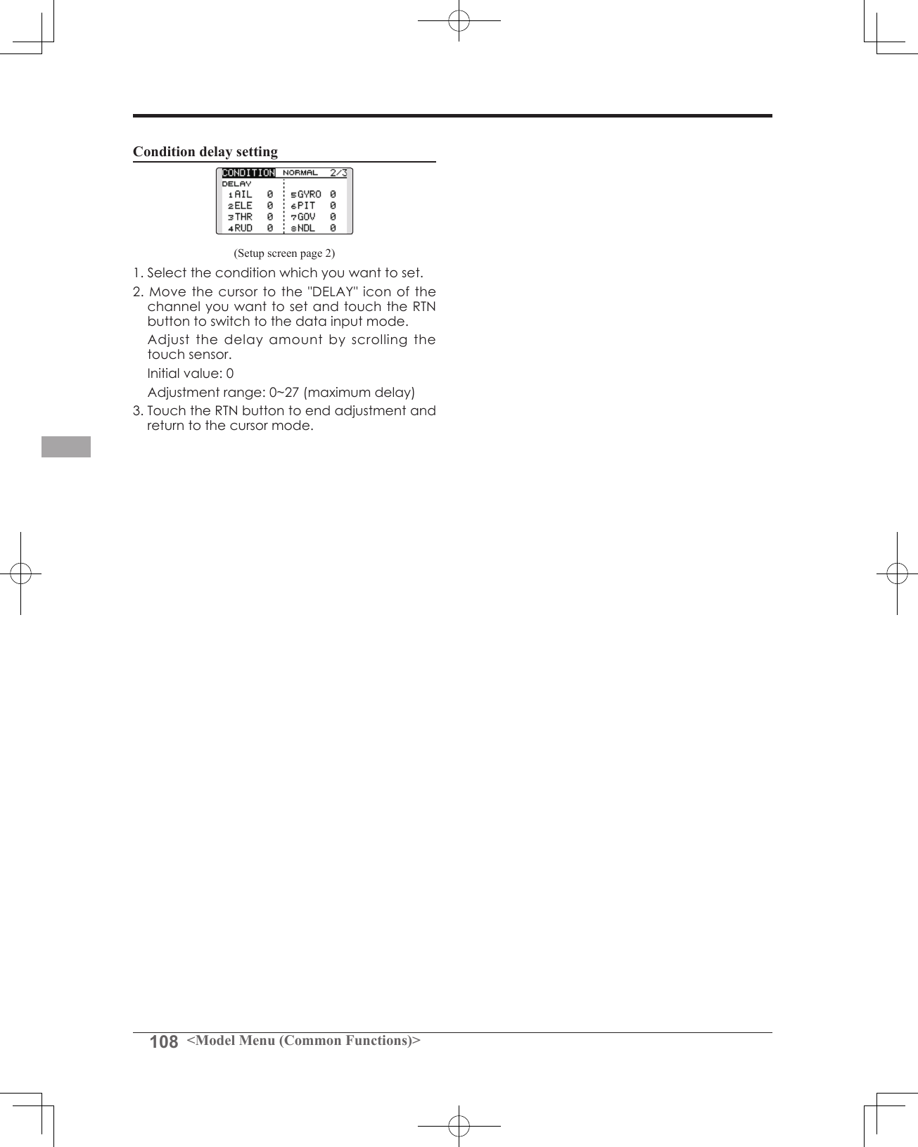
![107<Model Menu (Common Functions)>● Select the function name and return to the Model menu by touching the RTN button. Or the HOME/EXIT button is pushed.<SensorTouch™>RETURNCONDITION Flight condition's switch assignment, copy, priority change and condition delay can be set. [except airplane type]This function, in the Model menu, can be used to switch the settings of up to 5 ight conditions. Please note this is not applicable to airplane type selections.Note: To prevent accidental activation of any unused ight conditions during ight, set the switch setting of those unused conditions to null [--].● A Condition Delay function can be set. Unnecessary fuselage motion which may be generated when there are sudden changes in the servo positions and when there are variations in the operating time between channels during condition switching. The delay can be set for each channel to ensure maximum performance from your aircraft.When setting the delay function for a specic ight condition, the related function changes after a delay corresponding to the set amount.● If multiple conditions were set, their operational priority may be customized as desired.(Currently selected condition name)● Select [CONDITION] at the Model menu and access the setup screen shown below by touching the RTN button. Select the copy destination condition by scrolling the touch sensor. Then, touch the RTN button.*The current condition can not be selected for the copy destination condition.3. Move the cursor to the [COPY] item and touch the RTN button. A confirmation message appears. *The display blinks.4. Touch the RTN button for one second and the copying is completed. (Touch the S1 button to stop copying.)Priority change1. Move the cursor to the priority up-arrow or down-arrow you want to change and touch the RTN button. The priority of the corresponding condition is changed. (The last condition becomes the highest priority.)*The Normal condition cannot be changed or moved, its priority is always the lowest.Condition switch selection/deletion1. Move the cursor to the switch item of the condition you want to select/delete and access the switch setup screen by touching the RTN button and select the switch and ON direction.*For a detailed description of the setting method, see [Switch Setting Method] at the back of this manual.Condition copy(Setup screen page 3)1. Move the cursor to the [SOURCE] item and touch the RTN button to switch to the data input mode. Select the copy source condition by scrolling the touch sensor. Then, touch the RTN button.2. Move the cursor to the [DESTIN.] item and touch the RTN button.Scrolling● Moving cursor● Selecting mode● Adjusting value● To next page (Condition name) (Condition switch)](https://usermanual.wiki/Futaba/T14SG-24G.User-Manual-3/User-Guide-1894990-Page-27.png)
![109<Model Menu (Common Functions)>● Select the function name and return to the Model menu by touching the RTN button. Or the HOME/EXIT button is pushed.<SensorTouch™>RETURNDUAL RATE The angle and curve of each stick function can be set. [All model types]Dual rate function is used to adjust the amount of throw and the operational curve of the stick functions (aileron, elevator and rudder) for each ight condition or up to 5 rates for each function. For airplane type, it is also possible to adjust the operational curve of the throttle function.This is normally used after the End Point programming has been completed to define the maximum throw. When mixing is applied from one channel to another channel, both channels can be adjusted at the same time by adjusting the operation rate through the dual rate function.Neutral position of the dual rate curve can be set. Dual rate curve of FLAP, FLAP3, BUTTERFLY, and CAMBER function can be set. (Airplane/Glider)*FLAP3 and BUTTERFLY are glider only functions.*EXP rate setting is not allowed in the FLAP, FLAP3,BUTTERFLY, and CAMBER functions.*Individual switch setting is not allowed in the FLAP,FLAP3, and BUTTERFLY, CAMBER functions. (Condition switching only)● Select [DUAL RATE] at the Model menu and access the setup screen shown below by touching the RTN button.(Currently selected circuit #)●Neutral positionScrolling● Moving cursor● Selecting mode● Adjusting value● To next page●Left/right (up/down) rate●Operation curve (left/right, up/down)●Switch selection[Airplane][Helicopter/glider]●Condition Mode selection●Switch mode selection●Condition selection●Switch selection*Up to ve rates for each function●Function selection](https://usermanual.wiki/Futaba/T14SG-24G.User-Manual-3/User-Guide-1894990-Page-29.png)
![110 <Model Menu (Common Functions)>Dual rate setting procedure1. Function selection Move the cursor to the function selection item and touch the RTN button to switch to the data input mode. Select the function you want to adjust by scrolling the touch sensor. Touch the RTN button to the cursor mode.2. Switch selection Move the cursor to the circuit # item and access the switch setup screen by touching the RTN button. Select the switch activation method and the activation position (if applicable).*For a detailed description of the setting method, see [Switch Setting Method] at the back of this manual.3. Left/right (up/down) rate adjustment*Perform the settings below after changing to the circuit # or condition you want to adjust. Move the cursor to the rate item you want to adjust and touch the RTN button to switch to the data input mode. Adjust the rate by scrolling the touch sensor. Initial value: 100% Adjustment range: 0%~140%*When the RTN button is touched for one second, the servo operation position is reset to the initial value.) Touch the RTN button to end the adjustment and return to the cursor mode. Repeat this procedure for additional rate and other functions as desired.4. Operation curve (EXP curve) adjustment*Perform the settings below after changing to the circuit # or condition you want to adjust. Move the cursor to the EXP item you want to adjust and touch the RTN button to switch to the data input mode. Adjust the rate by scrolling the touch sensor. Initial value: 0% Adjustment range: -100%~+100%*When the RTN button is touched for one second, the servo operation position is reset to the initial value.)*Using the EXP curve is effective to smoothe or soften the control inputs around center to avoid over-controlling the model. This is often used for the ailerons, elevator and rudder and may be used with the throttle in the case of an airplane selection to smoothe the engine controls as well. Touch the RTN button to end adjustment and return to the cursor mode. Repeat this procedure for all other rates and functions as desired.5. Neutral position adjustment*Perform the settings below after changing to the circuit # or condition you want to adjust. Move the cursor to the [NT] item and touch the RTN button to switch to the data input mode. Adjust the rate by scrolling the touch sensor. Initial value: 0% Adjustment range: -100%~+100%*When the RTN button is touched for one second, the neutral position is reset to the initial value.) Touch the RTN button to the cursor mode.](https://usermanual.wiki/Futaba/T14SG-24G.User-Manual-3/User-Guide-1894990-Page-30.png)
![111<Model Menu (Common Functions)>● Select the function name and return to the Model menu by touching the RTN button. Or the HOME/EXIT button is pushed.<SensorTouch™>RETURNPROG. MIX Program mixing which can be freely customized. Up to five mixings can be used for each model. [All model types]Programmable mixing may be used to correct undesired tendencies of the aircraft, and it may also be used for unusual control congurations. Mixing means that the motion of a command channel, called the "master," is added to the motion of the mixed channel, called "slave."You may choose to have the Master's trim added to the Slave channel response ("Trim" setting). The mixing curve (Linear/5-point) can be changed. You may select Mixing ON/OFF switch, control or you may choose to have mixing remaining on all the time. The Programmable mixing includes a powerful link function, which allows Programmable mixing to be linked with the special mixing functions, or with other programmable mixing functions. The link function can be set up for Master and Slave channel individually.● Select [PROG. MIX] at the Model menu and access the setup screen shown below by touching the RTN button.●Link setting●Trim mode setting●ON/OFFScrolling● Moving cursor● Selecting mode● Adjusting value● To next pageMix setup screen call● Move the cursor to the mix # whose function you want to activate and access the setup screen by touching the RTN button.[Linear curve] [5-point curve]●Current mix No.●Master CH●Slave CH●Switch selection●Curve selection ●Curve selection●Offset rate(X, Y)●Mixing rate (Left/right, up/down)●Point rate (point1-5)●Mix #Prog. mix setting procedure●Activate the function. Move the cursor to the [ACT] item and touch the RTN button to switch to the data input mode. Select the ACT mode by scrolling the touch sensor. *The display blinks. Touch the RTN button to activate the function and return to the cursor mode.*The function is activated. (ON or OFF display)*ON/OFF switch and mix rate are not set even though the function is activated.](https://usermanual.wiki/Futaba/T14SG-24G.User-Manual-3/User-Guide-1894990-Page-31.png)
![112 <Model Menu (Common Functions)>●ON/OFF switch setting Move the cursor to the switch item and access the switch setup screen by touching the RTN button and select the switch and ON direction.*For a detailed description of the setting method, see [Switch Setting Method] at the back of this manual.*Always on when [--].●Master channel setting1. Move the cursor to the [MASTER] item and touch the RTN button to switch to the data input mode. Select the function by scrolling the touch sensor. *The display blinks. Touch the RTN button to change the function and return to the cursor mode.2. When you want to link this mixing with other mixes, move the cursor to the [LINK] item and touch the RTN button to switch to the data input mode. Select the link mode, either [+] or [-], by scrolling the touch sensor.*The display blinks. Touch the RTN button to set the link mode and return to the cursor mode.*Check to ensure that the link mode is functioning properly by operating the mix accordingly.*Master channel control can be set to activate based on the amount of stick input, or VR input, neither of which include ATV, D/R, and mixing selection. In this case, the switch setup screen is displayed by touching the RTN button with "H/W" selected in the function selection. Select master channel control. (To terminate the "H/W" selection, select the [--] display and touch the RTN button.●Slave channel setting1. Move the cursor to the [SLAVE] item and touch the RTN button to switch to the data input mode. Select the function by scrolling the touch sensor. *The display blinks. Touch the RTN button to change the function and return to the cursor mode.2. When you want to link this mixing with other mixes, move the cursor to the [LINK] item and touch the RTN button to switch to the data input mode. Select the link mode to [+] or [-] by scrolling the touch sensor.*The display blinks. Touch the RTN button to set the link mode and return to the cursor mode.*Check the direction by actual operation.●Trim mode ON/OFF setting1. When changing the trim mode, move the cursor to the [TRIM] item and touch the RTN button to switch to the data input mode. Select ON/OFF by scrolling the touch sensor.*The display blinks. Touch the RTN button to change the trim mode ON/OFF and return to the cursor mode.*To incorporate the mixing from the master trim select [ON]. If trim is not desired, select [OFF].*Effective when a function is set in the master channel.●Linear curve setting[Rate setting]1. Move the cursor to the mixing rate setting item and touch the RTN button to switch to the data input mode. Adjust the rate by scrolling the touch sensor. Initial value: 0% Adjustment range: -100%~+100%*When the RTN button is touched for one second, the servo operation position is reset to the initial value. Touch the RTN button to end adjustment and return to the cursor mode.2. Repeat this procedure for all other rates as desired.[Offsetting the curve horizontally in the vertical or horizontal direction]1. Move the cursor to the [OFFS] setting item and touch the RTN button to switch to the data input mode. Adjust the offset rate by scrolling the touch sensor. Initial value: 0% Adjustment range: -100%~+100%*When the RTN button is touched for one second, the servo operation position is reset to the initial value.) Touch the RTN button to end the adjustment and return to the cursor mode.2. Repeat this procedure for the other direction.●5-point curve setting[Rate setting]1. Move the cursor to the point rate setting item you want to adjust and touch the RTN button to switch to the data input mode. Adjust the rate by scrolling the touch sensor. Initial value: 0% Adjustment range: -100%~+100%*When the RTN button is touched for one second, the servo operation position is reset to the initial value.) Touch the RTN button to end the adjustment and return to the cursor mode.2. Repeat this procedure for each point as desired.](https://usermanual.wiki/Futaba/T14SG-24G.User-Manual-3/User-Guide-1894990-Page-32.png)
![113<Model Menu (Common Functions)>● Select the function name and return to the Model menu by touching the RTN button. Or the HOME/EXIT button is pushed.<SensorTouch™>RETURNFUEL MIX Dedicated mixing used to adjust the fuel mixture of applicable engines. [Airplane/helicopter]This function is utilized to rene inight needle adjustments of engines that offer mixture control carburetors.Note: Initial settings does not assign fuel mix to any channel. Prior to utilizing the Fuel Mix settings, select an unused channel on your receiver and assign it accordingly for the mixture control. Additionally, please make sure that your [Control] and [Trim] are set to null [--].● Select [FUEL MIX] at the Model menu and access the setup screen shown below by touching the RTN button.Scrolling● Moving cursor● Selecting mode● Adjusting value● To next page●Acceleration setting●Needle high trim selection[Airplane type][Helicopter type]●Engine cut setting●Mixing curve copy function Move the COPY item and touch the RTN button to switch to the data input mode. Select the copy destination condition by scrolling the touch sensor and touch the RTN button. Select the [YES] and touch the RTN button.](https://usermanual.wiki/Futaba/T14SG-24G.User-Manual-3/User-Guide-1894990-Page-33.png)
![114 <Model Menu (Common Functions)>reset to the initial value.) Touch the RTN button to end adjustment and return to the cursor mode.*Needle high trim works as high trim based on the center. (Works like ATL trim.)●Acceleration setting (Airplane)*This function is used to adjust the needle/engine rise characteristics during acceleration. This enables an acceleration function which temporarily increases the needle operation from the throttle stick. This function is used when there are symptoms of the mixture being too lean or too rich, which would be generated by sudden throttle stick inputs. [Acceleration rate setting (RATE)]*Acceleration can be adjusted for both high and low settings. [Damping rate setting (DUMPING)]*The return time after operation (Dumping) can be set. Move the cursor to the rate item you want to change and touch the RTN button to switch to the data input mode. Adjust the rate by scrolling the touch sensor.*When the RTN button is touched for one second, the rate is reset to the initial value.) Touch the RTN button to end adjustment and return to the cursor mode. [Operation point setting (ACT POS)]*The operation point at which the acceleration setting will occur. If this point is exceeded, acceleration is performed. Move the cursor to the [ACT POS] item and hold the throttle stick to the position you want to change and touch the RTN button for one second. Note: When using the acceleration function, since the needle stroke is large, adjust your settings so there is no binding of your linkage.●Engine cut setting* Operation linked with the throttle hold function, throttle cut function, and idle down function is possible. The throttle cut position can be adjusted accordingly. Set it to the full closed position. Move the cursor to the throttle cut or idle down item and touch the RTN button to switch to the data input mode. Adjust the servo position by scrolling the touch sensor. Initial value: THR CUT: 17%, IDLE DOWN: 0% Adjustment range: THR CUT: 0~50%, IDLE DOWN: 0~100%*When the RTN button is touched for one second, the rate is reset to the initial value.) Touch the RTN button to end the adjustment and return to the cursor mode.Setting method*Before using this function, assign the [FUEL MIX] function to an unused channel in the Linkage menu [FUNCTION] .●Activate the function.1. Move the cursor to the [ACT] item and touch the RTN button to switch to the data input mode. Select the ACT mode by scrolling the touch sensor. *The display blinks. Touch the RTN button to activate the function and return to the cursor mode. (ON is displayed.)2. Move the cursor to the [MIX] item and touch the RTN button to switch to the data input mode. Select the mixing mode you want to change by scrolling the touch sensor. *The display blinks. Touch the RTN button to change the mode and return to the cursor mode.*When [MIX] is selected at the [MIX] icon, the throttle curve data that is set becomes the mix master. When [UNMIX] is selected, the throttle stick position becomes the master.●5-point curve setting1. Move the cursor to the point rate setting item you want to adjust and touch the RTN button to switch to the data input mode. Adjust the rate by scrolling the touch sensor. Initial value: 0% Adjustment range: -100%~+100%*When the RTN button is touched for one second, the servo operation position is reset to the initial value.) Touch the RTN button to end adjustment and return to the cursor mode.2. Repeat this procedure for each point.●Needle high trim setting1. Move the cursor to the needle high trim selection item and access the switch setup screen by touching the RTN button. Select the needle high trim lever.*For a detailed description of the setting method, see [Switch Setting Method] at the back of this manual.2. Move the cursor to the TRIM rate item and touch the RTN button to switch to the data input mode. Adjust the trim rate by scrolling the touch sensor. Initial value: 0% Adjustment range: -30%~+30%*When the RTN button is touched for one second, the rate is](https://usermanual.wiki/Futaba/T14SG-24G.User-Manual-3/User-Guide-1894990-Page-34.png)
![115<Model Menu (Airplane/Glider Functions)>MODEL MENU (AIRPLANE/GLIDER FUNCTIONS)The dedicated mixes, etc. that are applicable when an airplane or glider model type is selected are displayed in this Model menu functions section. Prior to adjusting any of these mixes, etc. use the Model Type function in the Linkage menu to select the model type, wing type, and tail type matched to the aircraft. Other settings reset the data used in mixing function, etc.For glider, many dedicated mixes can be set for each flight condition, as required. To switch the settings for each condition by switch or stick position, use the Condition Select function to add flight conditions. (Up to five conditions can be used)Note: The T14SG is designed so that the airplane and glider model types can utilize aircraft of the same wing type.The functions common to airplanes and gliders, with the exception of some dedicated functions, are written without regard to the model type.While there may be differences, depending on the number of servos, etc. the wing type used, etc. the setup screens in the instruction manual are typical examples.Model Menu functions listPITCH CURVECompatible with VPP (Variable Pitch Propeller) function. [Airplane, general]THR CURVETHR curve function adjusts the throttle operation curve for optimum engine speed to throttle stick movement. [Airplane/glider, general]THR DELAYTHR-DELAY function is used to slow the response of the throttle stick to simulate the slow response of a turbine engine, etc. [Airplane, general]AIL DIFFERENTIALThe left and right aileron differential can be adjusted independently. For glider, the differential rate in buttery mixing can be adjusted.[Airplane/glider, 2 ailerons or more]FLAP SETTINGThe up/down travel of each ap can be adjusted independently for each servo according to the wing type. [Airplane/glider, 2 aps or more]AIL to CAMB.FLPThis mix operates the camber aps in the aileron mode. It improves the roll axis characteristics. [Airplane/glider, 2 ailerons + 2 aps or more]AIL to BRKFLPThis mix operates the brake aps in the aileron mode. It improves the roll axis characteristics. [Glider, 4 aps]*The Model menu screen depends on the model type.● Access the model menu shown below by touching the MDL button twice at the home screen, etc.● Select the function name and return to the Model menu by touching the RTN button. Or a HOME/EXIT button is pushed.<SensorTouch™>● Select the function you want to set and access the setup screen by touching the RTN button. Scrolling● Moving cursor● To next pageRETURN](https://usermanual.wiki/Futaba/T14SG-24G.User-Manual-3/User-Guide-1894990-Page-35.png)
![116 <Model Menu (Airplane/Glider Functions)>AIL 3(Chip Aileron) AIL 4(Chip Aileron)AIL1(Main Aileron) AIL 2(Main Aileron)FLP 2(Camber Flap)FLP 1(Camber Flap)ELEVATOR(ELEVATOR 2)V-TAIL AILVATORFLP 3(Brake Flap)FLP 4(Brake Flap) RUDDER 2 WingletRUDDER 1RUDDER (RUDDER 2) Wingletat Flying wing at Flying wing( ) ( )ELEVATOR ELEVATOR 2(AILERON 5) (AILERON 6)AIL to RUDThis mix is used when you want to coordinate the rudder with aileron operation for banking at shallow angles. [Airplane/glider, general]RUD to AILThis function is used when you want to mix the ailerons with rudder input. Rudder is applied during rolling maneuvers such as knife edge ight. [Airplane/glider, general]CAMBER MIXThis mix adjusts the camber and corrects the elevators. [Airplane/glider, 2 ailerons or more]ELE to CAMBERThis mix is used when you want to the mix camber aps with elevator to increase the lift of the model. [Airplane/glider, 2 ailerons or more]CAMB.FLP to ELEThis mix is used to correct for changes in attitude when the camber flaps are utilized. [Airplane/glider, 2 ailerons + 1 ap or more]BUTTERFLY (Crow)This function is used to quickly slow the aircraft and/or reduce the altitude. [Glider, 2 ailerons or more (Flying: 2 ailerons + 1 ap or more)]TRIM MIXThe ailerons, elevators, and aps trim offset rate can be accessed by selecting a switch or condition selection as desired. [Glider, 2 ailerons or more]AIRBRAKEThis function is used when airbrakes are necessary when landing or when diving, etc. during ight. (Airplane, 2 ailerons or more)GYROThis is a dedicated mix when a GYA Series gyro is used. [Airplane/glider, general]V-TAILThis function incorporates the elevators and rudder input for use with V-tail models. [Airplane/glider, V-tail specications]AILEVATOR (DUAL ELEVATOR)This function adjusts the elevators and ailerons of models with elevator specifications. [Airplane/glider, ailevator specications]WINGLETThis function adjusts the left and right rudders of winglet models. [Airplane/glider, winglet specications]MOTORThis function adjusts the operation speed when the motor of an F5B or other such EP glider is started by a switch. [Airplane/glider, general]RUD to ELEThis function is used to correct rolling maneuvers such as, knife edge ight. [Airplane, general]SNAP ROLLThis function selects the snap roll switch and adjusts the amount of servo input. Servo speed can also be adjusted. [Airplane general]](https://usermanual.wiki/Futaba/T14SG-24G.User-Manual-3/User-Guide-1894990-Page-36.png)
![117<Model Menu (Airplane/Glider Functions)>● Select the function name and return to the Model menu by touching the RTN button. Or the HOME/EXIT button is pushed.<SensorTouch™>RETURNThis function adjusts the pitch curve for VPP (Variable Pitch Propeller) airplane.*Up to 3 conditions can be set.*The priority increases in condition 1→2→3 order.NOTE: When VPP is not assigned to any channel, the pitch curve is not displayed in the model menu. In this case, assign VPP to any channel on the function screen.● Select [PIT CURVE] at the Model menu and access the setup screen shown below by touching the RTN button.●Curve rateScrolling● Moving cursor● Selecting mode● Adjusting value● To next pagePIT CURVE [Corresponding model type]: Airplane, generalSetting method●VPP condition selection1. Move the cursor to the # button at the top right side of the screen and touch the RTN button to switch to the data input mode. Select the VPP condition by scrolling the touch sensor. *The display blinks. Touch the RTN button to call the setting screen and return to the cursor mode.2. Move the cursor to the switch item and touch the RTN button to access the selection screen. Select the switch and set its ON direction.*For a description of the switch selection method, see the description at the back of this manual. Set the VPP condition 2 and 3 switch.*The VPP conditions can also be checked in the HOME screen.●5-point curve setting[Curve rate setting]1. Move the cursor to the curve rate setting item you want to adjust and touch the RTN button to switch to the data input mode. Adjust the rate by scrolling the touch sensor. Initial value: 0% Adjustment range: 0%~100%*When the RTN button is touched for one second, the rate is reset to the initial value. Touch the RTN button to end the adjustment and return to the cursor mode.2. Repeat this procedure for each point.[Moving curve point]1. Move the cursor to the curve point setting item you want to adjust and touch the RTN button to switch to the data input mode. Adjust the curve point by scrolling the touch sensor. Initial value: P1: (0%), P2: 25%, P3: 50%, P4: 75%, P5: (100%) Adjustment range: Up to 2.5% in front of the adjoining point*When the RTN button is touched for one second, the curve position is reset to the initial value.) Touch the RTN button to end the adjustment and return to the cursor mode.2. Repeat this procedure for each point.[Deleting/returning curve point] Move the cursor to the curve point setting item you want to delete/return and touch the RTN button for one second.●Curve point](https://usermanual.wiki/Futaba/T14SG-24G.User-Manual-3/User-Guide-1894990-Page-37.png)
![118 <Model Menu (Airplane/Glider Functions)>● Select the function name and return to the Model menu by touching the RTN button. Or the HOME/EXIT button is pushed.<SensorTouch™>RETURNThis function adjusts the throttle curve for optimum engine speed from throttle stick input.*When throttle curve is set to ON when there is no throttle function; this curve acts as the motor function.NOTE: If this throttle curve function is activated, you can not use the THR-EXP function within the DUAL RATE function simultaneously.● Select [THR CURVE] at the Model menu and access the setup screen shown below by touching the RTN button.●Curve rateScrolling● Moving cursor● Selecting mode● Adjusting value● To next pageTHR CURVE [Corresponding model type]: Airplane/glider, generalSetting method●Activate the function.1. Move the cursor to the [ACT] item and touch the RTN button to switch to the data input mode. Select the ON mode by scrolling the touch sensor. *The display blinks. Touch the RTN button to activate the function and return to the cursor mode.●5-point curve setting[Curve rate setting]1. Move the cursor to the curve rate setting item you want to adjust and touch the RTN button to switch to the data input mode. Adjust the rate by scrolling the touch sensor. Initial value: 0% Adjustment range: 0%~100%*When the RTN button is touched for one second, the rate is reset to the initial value.) Touch the RTN button to end the adjustment and return to the cursor mode.2. Repeat this procedure for each point.[Moving curve point]1. Move the cursor to the curve point setting item you want to adjust and touch the RTN button to switch to the data input mode. Adjust the curve point by scrolling the touch sensor. Initial value: P1: (0%), P2: 25%, P3: 50%, P4: 75%, P5: (100%) Adjustment range: Up to 2.5% in front of the adjoining point*When the RTN button is touched for one second, the curve position is reset to the initial value.) Touch the RTN button to end the adjustment and return to the cursor mode.2. Repeat this procedure for each point.[Deleting/returning curve point] Move the cursor to the curve point setting item you want to delete/return and touch the RTN button for one second.●Curve point](https://usermanual.wiki/Futaba/T14SG-24G.User-Manual-3/User-Guide-1894990-Page-38.png)
![119<Model Menu (Airplane/Glider Functions)>● Select the function name and return to the Model menu by touching the RTN button. Or the HOME/EXIT button is pushed.<SensorTouch™>RETURNTHR-DELAY function is used to slow the response of the throttle stick to simulate the slow response of a turbine engine, etc.*This function is the same as THR of servo speed. If it sets up in great numbers, it overlaps and a THR servo becomes late further. Please do not let me overlap. Use either.● Select [THR DELAY] at the Model menu and access the setup screen shown below by touching the RTN button.Scrolling● Moving cursor● Selecting mode● Adjusting value● To next pageTHR DELAY [Corresponding model type]: Airplane, generalSetting method●Operation speed (delay) setting1. Move the cursor to the [DELAY] item and touch the RTN button to switch to the data input mode. Adjust the delay rate by scrolling the touch sensor. Initial value: 0 Adjustment range: 0~27 (maximum delay)*When the RTN button is touched for one second, the rate is reset to the initial value.) Touch the RTN button to activate the function and return to the cursor mode.](https://usermanual.wiki/Futaba/T14SG-24G.User-Manual-3/User-Guide-1894990-Page-39.png)
![120 <Model Menu (Airplane/Glider Functions)>● Select the function name and return to the Model menu by touching the RTN button. Or the HOME/EXIT button is pushed.<SensorTouch™>RETURNAIL 3(Chip Aileron) AIL 4(Chip Aileron)AIL1(Main Aileron) AIL 2(Main Aileron)AIL DIFF. [Corresponding model type]: Airplane/glider, 2 ailerons or moreThe left and right aileron differential can be adjusted independently.For glider, the differential rate in buttery mixing can be adjusted.*The display screen is an example. The actual screen depends on the Model Type.Setting method●Aileron left/right adjustment Move the cursor to the aileron (AIL) 1~4 left (or right) setting item and touch the RTN button to switch to the data input mode. Adjust the aileron angles by scrolling the touch sensor when the stick is moved to the left (or right) end. Initial value: 100% Adjustment range: 0~120%*When the RTN button is touched for one second, the rate is reset to the initial value.) Touch the RTN button to end the adjustment and return to the cursor mode.(Currently selected condition name)● Select [AIL DIFF.] at the Model menu and access the setup screen shown below by touching the RTN button.Scrolling● Moving cursor● Selecting mode● Adjusting value● To next page[Airplane (2A+2F)][Glider (4A+2F)]● Aileron left/right adjustment●Aileron differential adjustment in buttery mixing Move the cursor to the [BUTTERFLY ADJUST] item and touch the RTN button to switch to the data input mode. Adjust the differential rate by scrolling the touch sensor. Initial value: 0% Adjustment range: -120~+120%*When the RTN button is touched for one second, the rate is reset to the initial value.) Touch the RTN button to end the adjustment and return to the cursor mode.](https://usermanual.wiki/Futaba/T14SG-24G.User-Manual-3/User-Guide-1894990-Page-40.png)
![121<Model Menu (Airplane/Glider Functions)>● Select the function name and return to the Model menu by touching the RTN button. Or the HOME/EXIT button is pushed.<SensorTouch™>RETURNFLP 2(Camber Flap)FLP 1(Camber Flap)FLP 3(Brake Flap) FLP 4(Brake Flap)FLAP SET. [Corresponding model type]: Airplane/glider, 2 aps or moreThe up/down travel of each ap (camber aps: FLP1/2, brake flaps: FLP3/4) can be adjusted independently for each servo according to the wing type.● The operation reference point of each ap can be offsetThe camber flaps of a 4-flap model can be mixed with the brake flaps. (BRKFLP to CMBFLP)● An ON/OFF switch can be set.*The display screen is an example. The actual screen depends on the model type.Setting method●Flap up/down adjustment Move the cursor to the flap (FLP) 1~4 Up or Down item according to the wing type and touch the RTN button to switch to the data input mode. Adjust the travel independently by scrolling the touch sensor. Initial value: +100% Adjustment range: -120~+120%*When the RTN button is touched for one second, the rate is reset to the initial value.) Touch the RTN button to end the adjustment and return to the cursor mode.●Reference point adjustment Move the cursor to the [OFFSET] item and touch the RTN button to switch to the data input mode. Adjust the operation reference point of each flap by scrolling the touch sensor. Initial value: 0% Adjustment range: -100~+100%*When the RTN button is touched for one second, the reference point is reset to the initial value.) Touch the RTN button to end the adjustment and return to the cursor mode.●Activate the Brake FLP to Camber FLP mixing Move the cursor to the [ACT] item and touch the RTN button to switch to the data input mode. Select the ACT mode by scrolling the touch sensor. *The display blinks. Touch the RTN button to activate the function and return to the cursor mode. (ON is displayed.) To select a switch, move the cursor to the [SW] item and touch the RTN button to call the selection screen. Select the switch and set its ON direction. (Always ON at "--" setting)*For a description of the switch selection method, see the description at the back of this manual.● Select [FLAP SET.] at the Model menu and access the setup screen shown below by touching the RTN button.Scrolling● Moving cursor● Selecting mode● Adjusting value● To next page(Glider: Currently selected condition name)●Operation reference point offset●Up /Down adjustment](https://usermanual.wiki/Futaba/T14SG-24G.User-Manual-3/User-Guide-1894990-Page-41.png)
![122 <Model Menu (Airplane/Glider Functions)>● Select the function name and return to the Model menu by touching the RTN button. Or the HOME/EXIT button is pushed.<SensorTouch™>RETURNAIL 3(Chip Aileron) AIL 4(Chip Aileron)AIL1(Main Aileron) AIL 2(Main Aileron)FLP 2(Camber Flap)FLP 1(Camber Flap)AIL to CMBFLP [Corresponding model type]: Airplane/glider, 2 ailerons + 2 flaps or moreThis mix operates the camber flaps (FLP1/2) in the aileron mode. When the aileron stick is manipulated, the ailerons and camber flaps perform aileron operation simultaneously to signicantly improve the roll axis.● The aileron left/right mixing rate of each ap servo can be independently adjusted.● An ON/OFF switch can be set.● Linking is possible: Link this mix to other mixes.● Adjustment of each ap servoSetting method●Activate the function Move the cursor to the [ACT] item and touch the RTN button to switch to the data input mode. Select the ACT mode by scrolling the touch sensor. *The display blinks. Touch the RTN button to activate the function and return to the cursor mode. (ON is displayed.) When selecting a switch, move the cursor to the [SW] item and touch the RTN button to call the selection screen. Select the switch and set its ON direction. (Always ON at "--" setting)*For a description of the switch selection method, see the description at the back of this manual.●Mixing rate adjustment Move the cursor to the flap (FLP) 1~2 left or right item according to the wing type and touch the RTN button to switch to the data input mode. Adjust the mixing rate independently by scrolling the touch sensor. Initial value: 0% Adjustment range: -120~+120%*When the RTN button is touched for one second, the rate is reset to the initial value.) Touch the RTN button to end the adjustment and return to the cursor mode.●Link mode setting When linking a mix, move the cursor to the [LINK] item and touch the RTN button to switch to the data input mode. Select the ON mode by scrolling the touch sensor. *The display blinks. Touch the RTN button to set the link mode and return to the cursor mode.● Select [AIL to CMBFLP] at the Model menu and access the setup screen shown below by touching the RTN button.*The display screen is an example. The actual screen depends on the model type.Scrolling● Moving cursor● Selecting mode● Adjusting value● To next page(Glider: Currently selected condition name)](https://usermanual.wiki/Futaba/T14SG-24G.User-Manual-3/User-Guide-1894990-Page-42.png)
![123<Model Menu (Airplane/Glider Functions)>● Select the function name and return to the Model menu by touching the RTN button. Or the HOME/EXIT button is pushed.<SensorTouch™>RETURNAIL 3(Chip Aileron) AIL 4(Chip Aileron)AIL1(Main Aileron) AIL 2(Main Aileron)FLP 3(Brake Flap) FLP 4(Brake Flap)AIL to BRAKEFLP [Corresponding model type]: Glider, 4 apsThis mix operates the brake flaps (FLP3/4) in the aileron mode. When the aileron stick is manipulated, the aileron and brake aps perform the aileron operation simultaneously and the roll axis is improved.● The aileron left and right mixing rates can be adjusted separately for each ap servo.● Mixing during flight can be turned ON/OFF by setting a switch. (Always ON at [--] setting)● Linking can be set: Link this mix to other mixes.● Select [AIL to BRKFLP] at the Model menu and access the setup screen shown below by touching the RTN button.Scrolling● Moving cursor● Selecting mode● Adjusting value● To next page● Adjustment of each ap servo*The display screen is an example. The actual screen depends on the model type.(Currently selected condition name)Setting method●Activate the function Move the cursor to the [ACT] item and touch the RTN button to switch to the data input mode. Select the ACT mode by scrolling the touch sensor. *The display blinks. Touch the RTN button to activate the function and return to the cursor mode. (ON is displayed.) When setting a switch, move the cursor to the [SW] item and touch the RTN button to access the selection screen. Select the switch and set its ON direction. (Always ON at "--" setting)*For a description of the switch selection method, see the description at the back of this manual.●Mixing rate adjustment Move the cursor to the flap (FLP) 3~4 left or right item and touch the RTN button to switch to the data input mode. Adjust the mixing rate independently by scrolling the touch sensor. Initial value: 0% Adjustment range: -120~+120%*When the RTN button is touched for one second, the rate is reset to the initial value.) Touch the RTN button to end the adjustment and return to the cursor mode.●Link mode setting To activate the mixing, move the cursor to the [LINK] item and touch the RTN button to switch to the data input mode. Select the ON mode by scrolling the touch sensor. *The display blinks. Touch the RTN button to set the link mode and return to the cursor mode.](https://usermanual.wiki/Futaba/T14SG-24G.User-Manual-3/User-Guide-1894990-Page-43.png)
![124 <Model Menu (Airplane/Glider Functions)>● Select the function name and return to the Model menu by touching the RTN button. Or the HOME/EXIT button is pushed.<SensorTouch™>RETURNRUDDER 2RUDDER RUDDERV-TAILRUDDER 2WingletRUDDER 1Wingletat Flying wing at Flying wing( ) ( )AIL 3 AIL 3(Chip Aileron) (Chip Aileron)AIL1(Main Aileron) AIL 2(Main Aileron)AIL to RUD [Corresponding model type]: Airplane/glider, generalUse this mix when you want to mix the rudders with aileron operation. This allows the aircraft to bank at a steep angle.● Mixing during flight can be turned ON/OFF by a switch. (Always ON at [--] setting)● The mixing rate can be adjusted.● Select [AIL to RUD] at the Model menu and access the setup screen shown below by touching the RTN button.*The display screen is an example. The actual screen depends on the model type.Scrolling● Moving cursor● Selecting mode● Adjusting value● To next page(Glider: Currently selected condition name)Setting method●Activate the function Move the cursor to the [ACT] item and touch the RTN button to switch to the data input mode. Select the ACT mode by scrolling the touch sensor. *The display blinks. Touch the RTN button to activate the function and return to the cursor mode. (ON is displayed.) When selecting a switch, move the cursor to the [SW] item and touch the RTN button to call the selection screen. Select the switch and set its ON direction. (Always ON at "--" setting)*For a description of the switch selection method, see the description at the back of this manual.●Mixing rate adjustment Move the cursor to the left or right item and touch the RTN button to switch to the data input mode. Adjust the mixing rate independently by scrolling the touch sensor. Initial value: 0% Adjustment range: -100~+100%*When the RTN button is touched for one second, the rate is reset to the initial value.) Touch the RTN button to end the adjustment and return to the cursor mode.](https://usermanual.wiki/Futaba/T14SG-24G.User-Manual-3/User-Guide-1894990-Page-44.png)
![125<Model Menu (Airplane/Glider Functions)>● Select the function name and return to the Model menu by touching the RTN button. Or the HOME/EXIT button is pushed.<SensorTouch™>RETURNRUDDER 2RUDDER RUDDERV-TAILRUDDER 2WingletRUDDER 1Wingletat Flying wing at Flying wing( ) ( )AIL 3 AIL 3(Chip Aileron) (Chip Aileron)AIL1(Main Aileron) AIL 2(Main Aileron)RUD to AIL [Corresponding model type]: Airplane/glider, generalThis function is used when you want to mix the ailerons with rudder input. It is used when rudder is applied during roll maneuvers such as, knife edge flight. It can be used to turn or bank scale models, large models, etc. like a full- size aircraft.● Mixing during flight can be turned ON/OFF by setting a switch. (Always ON at [--] setting)● Linking can be set: Link this mix to other mixes.● The mixing rate can also be adjusted.● A 5-point curve can be set at airplane model type.● Select [RUD to AIL] at the Model menu and access the setup screen shown below by touching the RTN button.*The display screen is an example. The actual screen depends on the model type.Scrolling● Moving cursor● Selecting mode● Adjusting value● To next pageSetting method●Activate the function Move the cursor to the [ACT] item and touch the RTN button to switch to the data input mode. Select the ACT mode by scrolling the touch sensor. *The display blinks. Touch the RTN button to activate the function and return to the cursor mode. (ON is displayed.) When setting a switch, move the cursor to the [SW] item and touch the RTN button to call the selection screen. Select the switch and set its ON direction. (Always ON at "--" setting)*For a description of the switch selection method, see the description at the back of this manual.●Mixing rate adjustment (glider) Move the cursor to the left or right item and touch the RTN button to switch to the data input mode. Adjust the mixing rate independently by scrolling the touch sensor. Initial value: 0% Adjustment range: -100~+100%*When the RTN button is touched for one second, the rate is reset to the initial value.) Touch the RTN button to end the adjustment and return to the cursor mode.●Link mode setting To activate the link mixing, move the cursor to the [LINK] item and touch the RTN button to switch to the data input mode. Select the ON mode by scrolling the touch sensor. *The display blinks. Touch the RTN button to set the link mode and return to the cursor mode.(Glider: Currently selected condition name)](https://usermanual.wiki/Futaba/T14SG-24G.User-Manual-3/User-Guide-1894990-Page-45.png)
![126 <Model Menu (Airplane/Glider Functions)>●5-point curve setting (airplane)[Curve rate setting]1. Move the cursor to the curve rate setting item (left side) you want to adjust and touch the RTN button to switch to the data input mode. Adjust the rate by scrolling the touch sensor. Adjustment range: -100%~+100%*When the RTN button is touched for one second, the rate is reset to the initial value.) Touch the RTN button to end the adjustment and return to the cursor mode.2. Repeat this procedure for each point.[Moving curve point]1. Move the cursor to the curve point setting item you want to adjust and touch the RTN button to switch to the data input mode. Adjust the curve point by scrolling the touch sensor. Adjustment range: Up to 2.5% in front of the adjoining point*When the RTN button is touched for one second, the curve position is reset to the initial value.) Touch the RTN button to end the adjustment and return to the cursor mode.2. Repeat this procedure for each point.[Deleting/returning curve point] Move the cursor to the curve point setting item you want to delete/return and touch the RTN button for one second.](https://usermanual.wiki/Futaba/T14SG-24G.User-Manual-3/User-Guide-1894990-Page-46.png)
![127<Model Menu (Airplane/Glider Functions)>● Select the function name and return to the Model menu by touching the RTN button. Or the HOME/EXIT button is pushed.<SensorTouch™>RETURNCAMBER MIX [Corresponding model type]: Airplane/glider, 2 ailerons or moreThis function adjusts the rate of camber operation for the wing camber (ailerons, camber flaps, brake flaps) in the negative and positive directions. The aileron, flap, and elevator rates can also be adjusted independently and attitude changes caused by camber operation can be corrected.*Initial setting assigns camber operation to side lever LS.● The up/down rates of the aileron, flap, and elevator servos can be adjusted. When the mixing direction is reversed by the linkage, adjustments can be made by changing the mixing rate polarity (+ or -).● Mixing during flight can be turned ON/OFF by setting a switch. (Always ON at [--] setting)● A condition delay can be set. A cut switch which can turn OFF the delay function can be set.●Condition delay cut switch●Condition delay setting●Aileron rate adjustment(Glider: Currently selected condition name)● Select [CAMBER MIX] at the Model menu and access the setup screen shown below by touching the RTN button.*The display screen is an example. The actual screen depends on the model type.Scrolling● Moving cursor● Selecting mode● Adjusting value● To next page●Flap rate adjustment●Elevator rate adjustment](https://usermanual.wiki/Futaba/T14SG-24G.User-Manual-3/User-Guide-1894990-Page-47.png)
![128 <Model Menu (Airplane/Glider Functions)>AIL 3(Chip Aileron) AIL 4(Chip Aileron)AIL1(Main Aileron) AIL 2(Main Aileron)FLP 2(Camber Flap)FLP 1(Camber Flap)ELEVATOR ELEVATOR 2V-TAILELEVATOR ELEVATOR 2AILVATORFLP 3(Brake Flap) FLP 4(Brake Flap)Setting method●Activate the function Move the cursor to the [ACT] item and touch the RTN button to switch to the data input mode. Select the ACT mode by scrolling the touch sensor. *The display blinks. Touch the RTN button to activate the function and return to the cursor mode. (ON is displayed.) When setting a switch, move the cursor to the [SW] item and touch the RTN button to call the selection screen. Select the switch and set its ON direction. (Always ON at "--" setting)*For a description of the switch selection method, see the description at the back of this manual.●Condition delay setting Move the cursor to the [COND.DELAY] item and touch the RTN button to switch to the data input mode. Adjust the condition delay by scrolling the touch sensor. Initial value: 0 Adjustment range: 0~27*When the RTN button is touched for one second, the rate is reset to the initial value.) Touch the RTN button to end the adjustment and return to the cursor mode. When setting a cut switch, move the cursor to the [CUT-SW] item and touch the RTN button to access the selection screen. Select the switch and set its ON direction. (Always ON at "--" setting)*For a description of the switch selection method, see the description at the back of this manual.●Rate adjustment The rates are adjusted by accessing the aileron, ap, and elevator rate screens. Move the cursor to the rate1 or rate2 item and touch the RTN button to switch to the data input mode. Adjust the rate independently by scrolling the touch sensor. Initial value: 0% Adjustment range: -100~+100%*When the RTN button is touched for one second, the rate is reset to the initial value.) Touch the RTN button to end the adjustment and return to the cursor mode.](https://usermanual.wiki/Futaba/T14SG-24G.User-Manual-3/User-Guide-1894990-Page-48.png)
![129<Model Menu (Airplane/Glider Functions)>● Select the function name and return to the Model menu by touching the RTN button. Or the HOME/EXIT button is pushed.<SensorTouch™>RETURNELE to CAMBER [Corresponding model type]: Airplane/glider, 2 ailerons or moreThis function is used when you want to mix the camber aps with elevator operation. When used, the flaps are lowered by up elevator, and lift is increased.● In-ight mixing can be turned ON/OFF by assigning this to a switch. (Always ON at [--] setting)● The mixing rate can be adjusted.● The point that has little effect near the neutral position of the elevator stick can be adjusted. (Glider only)Note: The elevator on the tailless wing will also be effected when this mix is activated.●Mixing rate adjustment Move the cursor to the up or down mixing rate item for each servo and touch the RTN button to switch to the data input mode. Adjust the rate independently by scrolling the touch sensor. Initial value: 0% Adjustment range: -100~+100%*When the RTN button is touched for one second, the rate is reset to the initial value.) Touch the RTN button to end the adjustment and return to the cursor mode.Setting method●Activate the function Move the cursor to the [ACT] item and touch the RTN button to switch to the data input mode. Select the ACT mode by scrolling the touch sensor. *The display blinks. Touch the RTN button to activate the function and return to the cursor mode. (ON is displayed.) When setting a switch, move the cursor to the [SW] item and touch the RTN button to call the selection screen. Select the switch and set its ON direction. (Always ON at "--" setting)*For a description of the switch selection method, see the description at the back of this manual.●Range setting (Glider only) Move the cursor to the [RANGE] item and hold the elevator stick to the desired position (upper or lower side) and then touch the RTN button for one second to set the range. *The mixing does not work near neutral of the elevator stick. Initial value: 0% Adjustment range: 0~100%(Glider: Currently selected condition name)● Select [ELE to CAMBER] at the Model menu and access the setup screen shown below by touching the RTN button.*The display screen is an example. The actual screen depends on the model type.Scrolling● Moving cursor● Selecting mode● Adjusting value● To next page](https://usermanual.wiki/Futaba/T14SG-24G.User-Manual-3/User-Guide-1894990-Page-49.png)
![130 <Model Menu (Airplane/Glider Functions)>● Select the function name and return to the Model menu by touching the RTN button. Or the HOME/EXIT button is pushed.<SensorTouch™>RETURNELEVATOR ELEVATOR 2V-TAILELEVATOR ELEVATOR 2AILVATORFLP 2(Camber Flap)FLP 1(Camber Flap)CMBFLP to ELE [Corresponding model type]: Airplane/glider,2 ailerons + 1 ap or moreWhen the camber/speed flaps are utilized, the aircraft might experience, a change in pitch. This mix compensates for such changes by incorporating elevator input.● The elevator servos up/down rates can be adjusted separately. If the mixing direction is reversed, change the mixing rate polarity (+ or –).● Mixing during flight can be turned ON/OFF by setting a switch. (Always ON at [--] setting)●Elevator rate adjustmentSetting method●Activate the function Move the cursor to the [ACT] item and touch the RTN button to switch to the data input mode. Select the ACT mode by scrolling the touch sensor. *The display blinks. Touch the RTN button to activate the function and return to the cursor mode. (ON is displayed.) When setting a switch, move the cursor to the [SW] item and touch the RTN button to call the selection screen. Select the switch and set its ON direction. (Always ON at "--" setting)*For a description of the switch selection method, see the description at the back of this manual.●Mixing rate adjustment Move the cursor to the RATE1 or RATE2 item and touch the RTN button to switch to the data input mode. Adjust the mixing rate independently by scrolling the touch sensor. Initial value: 0% Adjustment range: -120~+120%*When the RTN button is touched for one second, the rate is reset to the initial value.) Touch the RTN button to end the adjustment and return to the cursor mode.● Select [CMBFLP to ELE] at the Model menu and access the setup screen shown below by touching the RTN button.*The display screen is an example. The actual screen depends on the model type.Scrolling● Moving cursor● Selecting mode● Adjusting value● To next page(Glider: Currently selected condition name)](https://usermanual.wiki/Futaba/T14SG-24G.User-Manual-3/User-Guide-1894990-Page-50.png)
![131<Model Menu (Airplane/Glider Functions)>● Select the function name and return to the Model menu by touching the RTN button. Or the HOME/EXIT button is pushed.<SensorTouch™>RETURNBUTTERFLY [Corresponding model type]: Glider, Normal: 2 ailerons or moreFlying: 2 ailerons + 1 ap or moreThis function is utilized to quickly slow the aircraft and reduce altitude by simultaneously raising the left and right ailerons and lowering the aps (camber ap, brake ap). Butterfly (Crow) produces an extremely efcient landing conguration by accomplishing the following: 1. Slow the aircraft’s velocity. 2. Provide washout at the wing tips to reduce the tendency to tip stall.3. Create more lift toward the center of the wing allowing it to y at a slower speed● Mixing during flight can be turned ON/OFF by setting a switch. (Always ON at [--] setting)● The point at which the butterfly operation reference point can be offset. ● The operational speed of the ailerons and flaps can be adjusted.● The differential rate can be adjusted.*For a description of the setting method, see the aileron differential function.●Buttery operation reference point● Select [BUTTERFLY] at the Model menu and access the setup screen shown below by touching the RTN button.*The display screen is an example. The actual screen depends on the model type.Scrolling● Moving cursor● Selecting mode● Adjusting value● To next page(Currently selected condition name)● Servo speed setting●Elevator adjustment●Aileron/ap rate adjustment](https://usermanual.wiki/Futaba/T14SG-24G.User-Manual-3/User-Guide-1894990-Page-51.png)
![132 <Model Menu (Airplane/Glider Functions)>Setting method●Activate the function Move the cursor to the [ACT] item and touch the RTN button to switch to the data input mode. Select the ACT mode by scrolling the touch sensor. *The display blinks. Touch the RTN button to activate the function and return to the cursor mode. (ON is displayed.) When setting a switch, move the cursor to the [SW] item and touch the RTN button to call the selection screen. Select the switch and set its ON direction. (Always ON at "--" setting)*For a description of the switch selection method, see the description at the back of this manual.●Rate adjustment Move the cursor to the aileron, flap or elevator rate item and touch the RTN button to switch to the data input mode. Adjust the rate independently by scrolling the touch sensor. Initial value: 0% Adjustment range: -200~+200% (Elevator: -120~+120%)*When the RTN button is touched for one second, the rate is reset to the initial value.) Touch the RTN button to end the adjustment and return to the cursor mode.● Elevator compensation curve adjustmentOutput (Y) Position (X)Offset point Fixed (0) Fixed (offset position)2- Intermediate point Settable Settable1- End point Settable Fixed* The range where mixing does not work close to the neutral position of the elevator stick can be adjusted. (Glider only)*When offset is set, the curve is initialized.●Reference point adjustment Move the cursor to the [OFFSET] item and hold the airbrake stick to the desired position and then touch the RTN button for one second to set the butterfly operational reference point. Initial value: 0% (upper side) Adjustment range: 0~100% ●Servo speed setting Move the cursor to the aileron, flap or elevator speed item and touch the RTN button to switch to the data input mode. Adjust the rate by scrolling the touch sensor. Initial value: 0 Adjustment range: 0~27 (maximum delay)*When the RTN button is touched for one second, the rate is reset to the initial value.) Touch the RTN button to activate the function and return to the cursor mode.AIL 3(Chip Aileron) AIL 4(Chip Aileron)AIL1(Main Aileron) AIL 2(Main Aileron)FLP 2(Camber Flap)FLP 1(Camber Flap)ELEVATOR ELEVATOR 2V-TAILELEVATOR ELEVATOR 2AILVATORFLP 3(Brake Flap) FLP 4(Brake Flap)](https://usermanual.wiki/Futaba/T14SG-24G.User-Manual-3/User-Guide-1894990-Page-52.png)
![133<Model Menu (Airplane/Glider Functions)>● Select the function name and return to the Model menu by touching the RTN button. Or the HOME/EXIT button is pushed.<SensorTouch™>RETURNTRIM MIX [Corresponding model type]: Glider, 2 ailerons or moreThis function adjusts the trim offset rates of the ailerons, elevators, and aps (camber aps, brake aps) according to the ight status. As an example this function can be set up for launching, with speed aps and ailerons drooped, and a slight amount of up elevator, and can be used for high speed ying, with both ailerons and speed flaps reflexed slightly, and a bit of down elevator. To prevent sudden trim changes when switching ight conditions, a delay can be set to provide a ● Select [TRIM MIX] at the Model menu and access the setup screen shown below by touching the RTN button.*The display screen is an example. The actual screen depends on the model type.Scrolling● Moving cursor● Selecting mode● Adjusting value● To next pagesmooth transition between the two conditions. It is also possible to program a cut switch which will turn off the delay.Furthermore, you can set the auto switch, which will link the trim mix to a stick, switch, or dial. Additionally, the speed of the aileron, elevator, and ap servos can be adjusted.(Currently selected condition name)● Condition delay setting● Ailerons, flaps, and elevators servo speed setting●Auto switch selection● Ailerons, flaps, and elevators offset rate●Switch selection](https://usermanual.wiki/Futaba/T14SG-24G.User-Manual-3/User-Guide-1894990-Page-53.png)
![134 <Model Menu (Airplane/Glider Functions)>Setting method●Activate the function Move the cursor to the [ACT] item and touch the RTN button to switch to the data input mode. Select the ACT mode by scrolling the touch sensor. *The display blinks. Touch the RTN button to activate the function and return to the cursor mode. (ON is displayed.) When setting a switch, move the cursor to the switch item and touch the RTN button to access the selection screen. Select the switch and set its ON direction. (Always ON at "--" setting)*For a description of the switch selection method, see the description at the back of this manual.●Trim offset rate adjustment Move the cursor to the aileron, flap or elevator rate item and touch the RTN button to switch to the data input mode. Adjust the rate independently by scrolling the touch sensor. Initial value: 0% Adjustment range: -250~+250%*When the RTN button is touched for one second, the rate is reset to the initial value.) Touch the RTN button to end the adjustment and return to the cursor mode.●Condition delay setting Move the cursor to the [COND.DELAY] item and touch the RTN button to switch to the data input mode. Adjust the condition delay by scrolling the touch sensor. Initial value: 0 Adjustment range: 0~27*When the RTN button is touched for one second, the servo operation position is reset to the initial value.) Touch the RTN button to end the adjustment and return to the cursor mode. When setting a cut switch, move the cursor to the [CUT-SW] item and touch the RTN button to access the selection screen. Select the switch and set its ON direction. (Always ON at "--" setting)*For a description of the switch selection method, see the description at the back of this manual. ●Servo speed setting Move the cursor to the aileron, flap or elevator speed item and touch the RTN button to switch to the data input mode. Adjust the rate by scrolling the touch sensor. Initial value: 0 Adjustment range: 0~27 (maximum delay)*When the RTN button is touched for one second, the rate is reset to the initial value.) Touch the RTN button to activate the function and return to the cursor mode.●Auto switch selection When selecting an auto switch, move the cursor to the [AUTO-SW] item and touch the RTN button to access the selection screen. Select the switch and set its ON direction. (Always ON at "--" setting)*For a description of the switch selection method, see the description at the back of this manual.AIL 3(Chip Aileron) AIL 4(Chip Aileron)AIL1(Main Aileron) AIL 2(Main Aileron)FLP 2(Camber Flap)FLP 1(Camber Flap)ELEVATOR ELEVATOR 2V-TAILELEVATOR ELEVATOR 2AILVATORFLP 3(Brake Flap) FLP 4(Brake Flap)](https://usermanual.wiki/Futaba/T14SG-24G.User-Manual-3/User-Guide-1894990-Page-54.png)
![135<Model Menu (Airplane/Glider Functions)>● Select the function name and return to the Model menu by touching the RTN button. Or the HOME/EXIT button is pushed.<SensorTouch™>RETURNAIRBRAKE [Corresponding model type]: Airplane, 2 ailerons or moreThis function is used to increase the aircraft's drag and is useful for landing or diving, etc.The preset elevators and flaps (camber flap, brake flap) offset amount can be activated by a switch.The offset amount of the aileron, elevator, and flap servos can be adjusted as needed. Also the speed of the aileron, elevator, and ap servos can be adjusted. If the Auto Mode is activated, this will link the Airbrake to a stick, switch, or dial. A separate stick switch or dial can also be set as the ON/OFF switch.Setting example for F3A and other aperon specications(When 2 ailerons model type selected)Offset rate: AIL: [-35~-45%], AIL2: [-35~-45%], ELE: [+5~7%]Note: The input numerics are examples. Adjust the travel to match the aircraft.Mode setting: ACT: [ON] Switch: [SW-C] AUTO-SW: [--]● Select [AIRBRAKE] at the Model menu and access the setup screen shown below by touching the RTN button.*The display screen is an example. The actual screen depends on the model type.Scrolling● Moving cursor● Selecting mode● Adjusting value● To next page● Ailerons, flaps, and elevators servo speed setting●Auto switch selection● Ailerons, flaps, and elevators offset rate●Switch selection](https://usermanual.wiki/Futaba/T14SG-24G.User-Manual-3/User-Guide-1894990-Page-55.png)
![136 <Model Menu (Airplane/Glider Functions)>Setting method●Activate the function Move the cursor to the [ACT] item and touch the RTN button to switch to the data input mode. Select the ACT mode by scrolling the touch sensor. *The display blinks. Touch the RTN button to activate the function and return to the cursor mode. (ON is displayed.) When setting a switch, move the cursor to the switch item and touch the RTN button to access the selection screen. Select the switch and set its ON direction. (Always ON at "--" setting)*For a description of the switch selection method, see the description at the back of this manual.●Offset rate adjustment Move the cursor to the aileron, flap or elevator rate item and touch the RTN button to switch to the data input mode. Adjust the rate independently by scrolling the touch sensor. Initial value: 0% Adjustment range: -250~+250%*When the RTN button is touched for one second, the rate is reset to the initial value.) Touch the RTN button to end the adjustment and return to the cursor mode. ●Servo speed setting Move the cursor to the aileron, flap or elevator speed item and touch the RTN button to switch to the data input mode. Adjust the rate by scrolling the touch sensor. Initial value: 0 Adjustment range: 0~27 (maximum delay)*When the RTN button is touched for one second, the rate is reset to the initial value.) Touch the RTN button to return to the cursor mode.●Auto switch selection When setting a auto switch, move the cursor to the [AUTO-SW] item and touch the RTN button to access the selection screen. Select the switch and set its ON direction. (Always ON at "--" setting)*For a description of the switch selection method, see the description at the back of this manual.AIL 3(Chip Aileron) AIL 4(Chip Aileron)AIL1(Main Aileron) AIL 2(Main Aileron)FLP 2(Camber Flap)FLP 1(Camber Flap)ELEVATOR ELEVATOR 2V-TAILELEVATOR ELEVATOR 2AILVATORFLP 3(Brake Flap) FLP 4(Brake Flap)](https://usermanual.wiki/Futaba/T14SG-24G.User-Manual-3/User-Guide-1894990-Page-56.png)
![137<Model Menu (Airplane/Glider Functions)>● Select the function name and return to the Model menu by touching the RTN button. Or the HOME/EXIT button is pushed.<SensorTouch™>RETURNGYRO [Corresponding model type]: Airplane/glider, generalThis function is used when a GYA Series gyro is used to stabilize the aircraft's attitude. The sensitivity and operation mode (Normal mode/AVCS mode) can be changed via a switch.● Three rates (Rate 1/Rate 2/Rate 3) can be switched.● Up to 3 axes (Gyro/Gyro 2/Gyro 3) can be simultaneously controlled.Note: This setting does not assign a sensitivity channel. To do so, use the Linkage menu prior to assigning the sensitivity channel (Gyro/Gyro2/Gyro3), be sure to select an unused channel. Set the [Control] and [Trim] settings other than Function to [--].● The operation mode (AVCS/NOR) and sensitivity of the three axis Gyro/Gyro2/Gyro3 can be set.● Select [GYRO] at the Model menu and access the setup screen shown below by touching the RTN button.Scrolling● Moving cursor● Selecting mode● Adjusting value● To next page(Active rate # display)● Gyro type selection● ACT/INH● Switch selection● Rate1-3 setup screen selection[Rate 1 setup screen][Rate 2 setup screen][Rate 3 setup screen]Setting method*Prior to using the Function menu in the Linkage menu to assign the sensitivity channel (Gyro/Gyro2/Gyro3) select an unused channel. Set [Control] and [Trim] other than function to [--].●Rate1-3 setup screen selection Move the cursor to the setup screen selection item and touch the RTN button to switch to the data input mode. Select the setup screen # by scrolling the touch sensor. Touch the RTN button to change the setup screen and return to the cursor mode.●Activate the function Move the cursor to the [INH] item and touch the RTN button to switch to the data input mode. Select the ACT mode by scrolling the touch sensor. *The display blinks. Touch the RTN button to activate the function and return to the cursor mode.](https://usermanual.wiki/Futaba/T14SG-24G.User-Manual-3/User-Guide-1894990-Page-57.png)
![138 <Model Menu (Airplane/Glider Functions)> When setting a rate selection switch, move the cursor to the switch item and touch the RTN button to access the selection screen. Select the switch and set its ON direction. (Always ON at "--" setting)*For a description of the switch selection method, see the description at the back of this manual.●Gyro type selection Move the cursor to the gyro type selection item and touch the RTN button to switch to the data input mode. Select the gyro type by scrolling the touch sensor. [GY]: When a Futaba GYA gyro is used [NORM]: When using something other than Futaba GYA gyro is used. Touch the RTN button to change the gyro type and return to the cursor mode.*When a Futaba GYA gyro is used and [GY] type is selected, the sensitivity set value is directly read in both the AVCS and NORM modes.●Operation mode selection (GYA gyro) Move the cursor to the operation mode selection item and touch the RTN button to switch to the data input mode. Select the operation mode by scrolling the touch sensor. [AVCS]: AVCS mode [NORM]: Normal mode Touch the RTN button to change the operation mode and return to the cursor mode. ●Sensitivity setting Move the cursor to the sensitivity icon and touch the RTN button to switch to the data input mode. Adjust the sensitivity by scrolling the touch sensor. Initial value: 0% Adjustment range: 0~100%*When the RTN button is touched for one second, the sensitivity is reset to the initial value.) Touch the RTN button to return to the cursor mode.(Example) Setting three axis using a GYA430 and GYA431 (2)● Wing type: Aileron 2 servos mounted fuselage selected● Set Gyro 1 (GYA431AIL): CH5, Gyro 2 (GYA431ELE): CH7, Gyro 3 (GYA430RUD): CH8 at the Function menu of the Linkage menu.● Rate 1 [OFF][GY][SE][NORM][60%][NORM][60%][NORM][60%] Rate 2 [INH] Rate 3 [OFF][GY][SE][AVCS][60%][AVCS][60%][AVCS][60%]*Set so that Rate 1 is turned on at the back position of switch E and Rate 3 is turned ON at the front position. Since switch E is turned OFF at the center, Rate 2 remains [INH].R7008SBRudder servoElevator servoGYA430GYA431GYA431Aileron servoS.BUS/S.BUS2 port*When a S.BUS port is used R7008SB CH Mode is set to ModeB [D]. GAIN 0%AVCSNORMALWhen AVCS is used we recommend that the sensitivity CH be set to the 3-position.](https://usermanual.wiki/Futaba/T14SG-24G.User-Manual-3/User-Guide-1894990-Page-58.png)
![139<Model Menu (Airplane/Glider Functions)>● Select the function name and return to the Model menu by touching the RTN button. Or the HOME/EXIT button is pushed.<SensorTouch™>RETURNELEVATOR(RUDDER 2) RUDDER(ELEVATOR 2)V-TAIL [Corresponding model type]: Airplane/glider, V-tailThis function enables adjustments for left and right rudder angle changes during elevator and rudder operation of a V-tail airplane.V-tail is when two servos are used together to control rudder movement as elevators. In addition to each elevator side moving up and down together, each side moves in opposite directions when moving as rudders. On a V-tail, this is also known as a Ruddervator, as they serve the same purpose.(Rudder function) Left and right travel adjustment of rudder operation(Elevator function) Up and down travel adjustment of elevator operation● Select [V-TAIL] at the Model menu and access the setup screen shown below by touching the RTN button.Scrolling● Moving cursor● Selecting mode● Adjusting value● To next pageSetting method● Travel adjustment Move the cursor to the item you want to adjust and touch the RTN button to switch to the data input mode. Adjust the rate by scrolling the touch sensor. Initial value: +50% Adjustment range: -120~+120%*When the RTN button is touched for one second, the rate is reset to the initial value.) Touch the RTN button to return to the cursor mode.*If the mixing direction is reversed, adjustments can be made by changing the mixing rate polarity (+ or -).*If a large value of travel is specified, when the sticks are moved at the same time, the controls may bind or run out of travel. Decrease the travel until no binding occurs.](https://usermanual.wiki/Futaba/T14SG-24G.User-Manual-3/User-Guide-1894990-Page-59.png)
![140 <Model Menu (Airplane/Glider Functions)>● Select the function name and return to the Model menu by touching the RTN button. Or the HOME/EXIT button is pushed.<SensorTouch™>RETURNELEVATOR ELEVATOR 2(AILERON 5) (AILERON 6)AILEVATOR [Corresponding model type]: Airplane/glider, Ailevator (Effective only when 2 servos used at the elevators)This function improves the performance of the roll axis by operating the elevators as ailerons.Ailevator is where each elevator in a standard (conventional) or v-tail moves independently, like ailerons on a wing. In addition to each elevator side moving up and down together, each side moves in opposite directions when moving as an Ailevator. On a V-tail, this is also known as a Ruddervator, as they can serve the same purpose. Typically, both Ailevator and ailerons are coupled together to maximize roll performance, especially on larger wingspan planes.Note: Select Ailevator as the Model Type at the Model Type screen. This changes the output channel. Check the Function menu.(Aileron function)● When the elevators are used as ailerons, aileron travel of the left and right elevators can be adjusted.(Elevator function)● The up and down rate of both elevators when the elevator stick is moved can be individually adjusted.● Select [AILEVATOR] at the Model menu and access the setup screen shown below by touching the RTN button.Scrolling● Moving cursor● Selecting mode● Adjusting value● To next pageSetting method● Travel adjustment Move the cursor to the item you want to adjust and touch the RTN button to switch to the data input mode. Adjust the rate by scrolling the touch sensor. Initial value: ELE: +100%, AIL: 0% Adjustment range: -120~+120%*When the RTN button is touched for one second, the rate is reset to the initial value.) Touch the RTN button to return to the cursor mode.*If the mixing direction is reversed, adjustments can be made by changing the mixing rate polarity (+ or -).*If a large value of travel is specified, when the sticks are moved at the same time, the controls may bind or run out of travel. Decrease the travel until no binding occurs.](https://usermanual.wiki/Futaba/T14SG-24G.User-Manual-3/User-Guide-1894990-Page-60.png)
![141<Model Menu (Airplane/Glider Functions)>● Select the function name and return to the Model menu by touching the RTN button. Or the HOME/EXIT button is pushed.<SensorTouch™>RETURNRUDDER 1Wingletat Flying wing( )RUDDER 2Wingletat Flying wing( )WINGLET [Corresponding model type]: Airplane/glider, Flying wing onlyThis function adjusts the left and right rudder angles of airplanes with winglets.Winglets are used to improve the efficiency of aircraft by lowering the lift-induced drag caused by wingtip vortices. The winglet is a vertical or angled extension located at the tip of each wing. Winglets work by increasing the effective aspect ratio wing without adding greatly to the structural stress and hence necessary weight of its structure - an extension of wing span would also permit lowering of induced drag, though it would cause parasitic drag and would require boosting the strength of the wing and hence its weight. There would come a point at which no overall useful gains would be made. A winglet helps to solve this by effectively increasing the aspect ratio without adding to the span of the wing.(Rudder 1/2)● The travel during rudder stick operation can be individually adjusted.● Select [WINGLET] at the Model menu and access the setup screen shown below by touching the RTN button.Scrolling● Moving cursor● Selecting mode● Adjusting value● To next pageSetting method● Travel adjustment Move the cursor to the item you want to adjust and touch the RTN button to switch to the data input mode. Adjust the rate by scrolling the touch sensor. Initial value: +100% Adjustment range: -120~+120%*When the RTN button is touched for one second, the rate is reset to the initial value.) Touch the RTN button to return to the cursor mode.*If the mixing direction is reversed, change the mixing rate polarity (+ or -).](https://usermanual.wiki/Futaba/T14SG-24G.User-Manual-3/User-Guide-1894990-Page-61.png)
![142 <Model Menu (Airplane/Glider Functions)>● Select the function name and return to the Model menu by touching the RTN button. Or the HOME/EXIT button is pushed.<SensorTouch™>RETURNMOTOR [Corresponding model type]: Airplane/glider, generalThis function lets you set the speed when the motor of an F5B or other EP glider is started via a switch. The operation speed can be set for two ranges, slow speed flight and high speed flight (Speed 1/Speed 2). This function can also be operated as a safety function by programming it to a switch.● The In side and Out side operating speeds can be adjusted independently in 2 ranges (Speed 1/Speed 2).● The boundary between the 2 ranges can be set. (From Speed 1 to Speed 2)● The operational speed can only be activated at the initial operation. However, operation can be repeated by setting the switch to OFF before the operation is nished. When you want to reset one time operation, set the ACT/INH item to [INH] and then reset it to [ON]. ● The motor channel is controlled by SW-G. (Glider: Initial setting) When changing the switch or stick which controls the motor, rst change Function of the Linkage menu.● If the Model Type selected is Airplane, the MOTOR function is changed from INH to ON and it is not assigned to another channel, the changes from the throttle channel to the motor channel are enabled. Note: Initial setting does not assign a motor channel according to the model type. Prior to assigning the motor channel, nd an unused channel. Then, use the Function menu of the Linkage menu. Set [Control] to the switch you want to use and [Trim] to [--].Note: When using this function, always check the initial operation with the propeller removed.● Select [MOTOR] at the Model menu and access the setup screen shown below by touching the RTN button.Scrolling● Moving cursor● Selecting mode● Adjusting value● To next pageSetting method● Activate the function When using this function, move the cursor to the [ACT/INH] item and touch the RTN button to switch to the data input mode. Select the [ACT] by scrolling the touch sensor and touch the RTN button. When selecting the ON/OFF switch, move the cursor to the switch item and touch the RTN button to access the selection screen. Select the switch and set its ON direction. (Always ON at "--" setting)*For a description of the switch selection method, see the description at the back of this manual.● Motor off position setting Move the cursor to the [MOTOR OFF] item and touch the RTN button for one second when the motor function switch (SG, etc.) is in the motor OFF position you want to set. The direction of the motor switch is memorized. The screen graph display OFF direction also changes.Note:● First decide the motor OFF direction, and then set the speed. When you want to reset the motor OFF direction, also reset the speed.● We recommend that Motor OFF be set in combination with F/S.● Set the basic operation direction with the Reverse function to match the ESC used.● Always set the Motor OFF position.](https://usermanual.wiki/Futaba/T14SG-24G.User-Manual-3/User-Guide-1894990-Page-62.png)
![143<Model Menu (Airplane/Glider Functions)>Setting method● Activate the motor speed function When using motor speed function, move the cursor to the [INH] item and touch the RTN button to switch to the data input mode. Select the [ACT] by scrolling the touch sensor and touch the RTN button.● Sifting the boundary between the 2 ranges Move the cursor to the [SPEED 1>2] item and touch the RTN button to switch to the data input mode. Adjust the boundary position by scrolling the touch sensor. Initial value: 0% Adjustment range: -100~+100%*When the RTN button is touched for one second, the rate is reset to the initial value.) Touch the RTN button to return to the cursor mode.● Operation speed adjustment Move the cursor to the [IN] (on to off) or [OUT] (off to on) item and touch the RTN button to switch to the data input mode. Adjust the operation speed you want to set by scrolling the touch sensor. Initial value: 0 Adjustment range: 0~27*When the RTN button is touched for one second, the rate is reset to the initial value.) Touch the RTN button to return to the cursor mode.● Set/Reset the one time operation Move the cursor to the [ONE TIME] item and touch the RTN button to switch to the data input mode. Select the [ACT] by scrolling the touch sensor and touch the RTN button to set the one time operation.* When you want to reset one time operation, set the ACT/INH item to [INH] and then reset it to [ON].● Motor function switch current position●Start switch functionWhen active, the "START SW" allows the motor's state to change from OFF to ON. The motor is ON when the main SW and "START SW" are turned ON simultaneously. The motor changes to OFF only when the main SW is turned off. If "START SW" is turned OFF but the main SW is still ON, the motor remains ON.[START SW function example] When the throttle (motor) stick is assigned as the "START SW", and the low throttle position of the throttle curve is adjusted, the motor starts operating with the initial stick movement. The motor will not cease functionality even if the stick position is returned to it's lowest setting.●Trim effect / invalid setting in motor OFFIf one of the trim levers is assigned to the Motor function, it is possible to turn the motor off with the trim lever. To maintain compatibility after updating the T14SG/S, the trim setting is adjusted to the on position. However, it is suggested to return it to the off position accordingly in the programming of the transmitter.*Data Reset will return the trim setting to the off position.●Screen at the time of the motor OFF settingWhen the MOTOR OFF setting is highlighted, you will note the presence of the small cursor that indicates the MOTOR OFF position. To adjust this MOTOR OFF position, use the throttle stick to move the cursor accordingly. When satisfied with this position, press and hold the RTN button on the transmitter.*The larger cursor is used to indicate the output of the motor channel. This cursor reects any throttle curves and motor mixing which may be active.●Throttle curve buttonWhen "CURVE" button is chosen, a throttle curve screen opens. *When a throttle function is assigned to either channel, the "CURVE" button is not displayed because a throttle curve does not function as a motor curve.● ON/OFF direction](https://usermanual.wiki/Futaba/T14SG-24G.User-Manual-3/User-Guide-1894990-Page-63.png)
![144 <Model Menu (Airplane/Glider Functions)>● Select the function name and return to the Model menu by touching the RTN button. Or the HOME/EXIT button is pushed.<SensorTouch™>RETURNRUD to ELE [Corresponding model type]: Airplane, generalThis function is used when you want to mix elevator operation with rudder operation. It is used to correct undesirable tendencies when rudder is applied in rolling maneuvers such as, knife edge ight.● Mixing during flight can be turned ON/OFF by setting a switch. (Always ON at [--] setting)● Link mixing can be set: Links this mix to other mixes.● Select [RUD to ELE] at the Model menu and access the setup screen shown below by touching the RTN button.Scrolling● Moving cursor● Selecting mode● Adjusting value● To next pageSetting method●Activate the function Move the cursor to the [ACT] item and touch the RTN button to switch to the data input mode. Select the ACT mode by scrolling the touch sensor. *The display blinks. Touch the RTN button to activate the function and return to the cursor mode. (ON is displayed.) When selecting a switch, move the cursor to the [SW] item and touch the RTN button to call the selection screen. Select the switch and set its ON direction. (Always ON at "--" setting)*For a description of the switch selection method, see the description at the back of this manual.●5-point curve setting (airplane)[Curve rate setting]1. Move the cursor to the curve rate setting item (left side) you want to adjust and touch the RTN button to switch to the data input mode. Adjust the rate by scrolling the touch sensor. Adjustment range: -100%~+100%*When the RTN button is touched for one second, the rate is reset to the initial value.) Touch the RTN button to end the adjustment and return to the cursor mode.2. Repeat this procedure for each point.[Moving curve point]1. Move the cursor to the curve point setting item you want to adjust and touch the RTN button to switch to the data input mode. Adjust the curve point by scrolling the touch sensor. Adjustment range: Up to 2.5% in front of the adjoining point*When the RTN button is touched for one second, the curve position is reset to the initial value.) Touch the RTN button to end the adjustment and return to the cursor mode.2. Repeat this procedure for each point.[Deleting/returning curve point] Move the cursor to the curve point setting item you want to delete/return and touch the RTN button for one second.●Link mode setting When selecting the link mixing, move the cursor to the [LINK] item and touch the RTN button to switch to the data input mode. Select the ON mode by scrolling the touch sensor. *The display blinks. Touch the RTN button to set the link mode and return to the cursor mode.](https://usermanual.wiki/Futaba/T14SG-24G.User-Manual-3/User-Guide-1894990-Page-64.png)
![145<Model Menu (Airplane/Glider Functions)>● Select the function name and return to the Model menu by touching the RTN button. Or the HOME/EXIT button is pushed.<SensorTouch™>RETURNSNAP ROLL [Corresponding model type]: Airplane, generalThis function selects the switch and rate adjustment of ailerons, elevators, and rudder when a snap roll is performed.● Four snap roll directions can be set. (Right/up, right/down, left/up, left/down)● Operation mode: When [Master] mode is selected, the Snap Roll function is turned ON/OFF by the master switch. It is possible to set the direction switch was switched to the direction in which you want to snap roll. When [Single] mode is selected, the snap roll in each direction can be executed by means of independent switches and positions.● A safety switch can be set to prevent the inadvertent activation of the snap roll. For example, the landing gear is lowered, even if the switch is turned on accidentally the snap roll would not be executed. The snap roll switch is activated only when the safety switch is OFF.(Example) Setting example for F3A● Mode: [Master]● Safety SW: [SG] (Safety measure)● Master SW: [SH] (Main switch for executing snap roll)● Direction switches:*The snap roll up side left and right and down side left and right direction switches are selected here.Right/Up: OFF [SD]Right/Down: OFF [SD]Left/Up: OFF [SA]Left/Down: OFF [SA]● Master/single mode selection● Select [SNAP ROLL] at the Model menu and access the setup screen shown below by touching the RTN button.Scrolling● Moving cursor● Selecting mode● Adjusting value● To next page● Direction switches](https://usermanual.wiki/Futaba/T14SG-24G.User-Manual-3/User-Guide-1894990-Page-65.png)
![146 <Model Menu (Airplane/Glider Functions)>Setting method●Master/single mode selection Move the cursor to the [MODE] item and touch the RTN button to switch to the data input mode. Select the master or single mode by scrolling the touch sensor. *The display blinks. [MASTER]: Master mode [SINGLE]: Single mode Touch the RTN button to select the mode and return to the cursor mode. When setting a master switch, move the cursor to the [MASTER-SW] item and touch the RTN button to access the selection screen. Select the switch and set its ON direction.*For a description of the switch selection method, see the description at the back of this manual. When setting a safety switch, move the cursor to the [SAFETY-SW] item and touch the RTN button to access the selection screen. Select the switch and set its ON direction.●Direction switch selection Move the cursor to the direction switch item and touch the RTN button to access the selection screen. Select the switch and set its ON direction.*For a description of the switch selection method, see the description at the back of this manual.●Rate adjustment Move the cursor to the aileron, elevator or rudder item for each direction and touch the RTN button to switch to the data input mode. Adjust the rate independently by scrolling the touch sensor. Initial value: (Dependent upon the snap roll direction) Adjustment range: -150~+150%*When the RTN button is touched for one second, the rate is reset to the initial value.) Touch the RTN button to end the adjustment and return to the cursor mode.](https://usermanual.wiki/Futaba/T14SG-24G.User-Manual-3/User-Guide-1894990-Page-66.png)
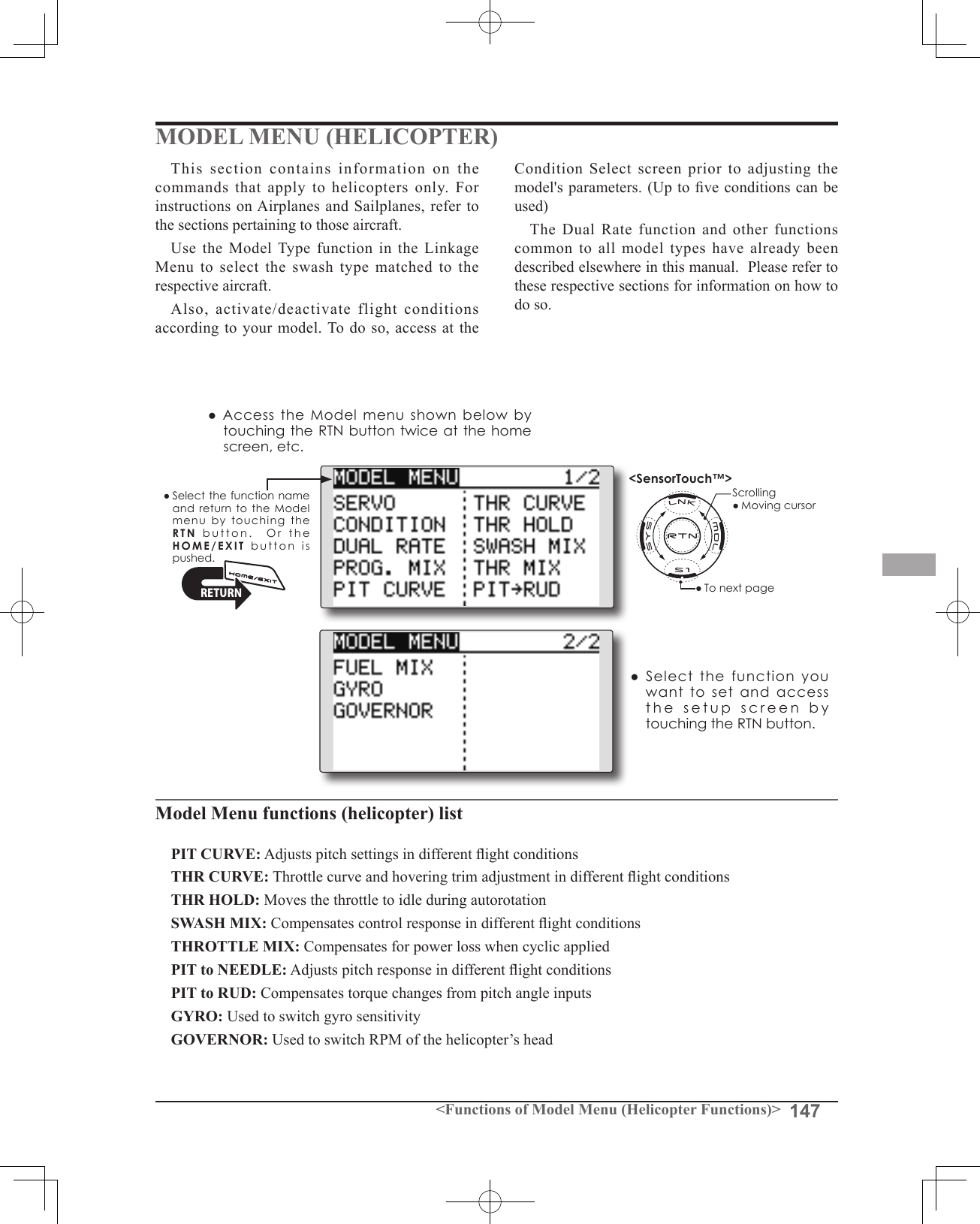
![148 <Functions of Model Menu (Helicopter Functions)>●SelectthefunctionnameandreturntotheModelmenubytouchingthe RTNbutton. Orthe HOME/EXIT buttonispushed.<SensorTouch™>RETURNPIT CURVE/PIT TRIMPitch CurveThis function adjusts the pitch operation curve for each flight condition to optmize the model's performance in relationship to the throttle stick position.*A simple curve can be created by reducing the number of input points to two or three, and then entering the specied value at the corresponding points.Normal curve adjustment*For normal curve, create a basic pitch curve centered about hovering. Use this function together with the THR Curve (Normal) function and adjust the curve so that up/down control is best at a constant engine speed.Idle up curve adjustment*For the high side pitch curve, set the maximum pitch so that it does not overload the engine. For the low side pitch curve, create curves matched to loop, roll, 3D, and other purposes and use the idle up curves according to the performance.Throttle hold curve adjustment*The throttle hold curve is used when executing auto rotations.Operation precautionsWarningWhen actually starting the engine and flying, always set the idle up condition switch to OFF and start the engine at idle.●Select[PITCURVE]attheModelmenuandaccessthesetupscreenshownbelowbytouchingtheRTNbutton.●PitchcurvecopyScrolling●Movingcursor●Selectingmode●Adjustingvalue●Tonextpage(Currently selected condition name)1.Movethecursortothecurvepointsettingitemyouwanttodelete/returnandtouchtheRTNbuttonforonesecond.●Pitch curve copy function MovethecursortoCOPYandtouchtheRTNbuttontoswitchtothedatainputmode.SelectthecopydestinationconditionbyscrollingthetouchsensorandtouchtheRTNbutton.Selectthe[YES]andtouchtheRTNbutton.●curverate ●curvepointSetting method●5-point curve setting[Curveratesetting]1.MovethecursortothecurveratesettingitemyouwanttoadjustandtouchtheRTNbuttontoswitchtothedatainputmode. Adjusttheratebyscrollingthetouchsensor. Initialvalue:P1:-100%,P2:-50%,P3:0%,P4:+50%,P5:+100% Adjustmentrange:-100%~+100%*When the RTN button is touched for one second, the rate is reset to the initial value. TouchtheRTNbuttontoendtheadjustmentandreturntothecursormode.2.Repeatthisprocedureforeachpointasdesired.[Movingcurvepoint]1.MovethecursortothecurvepointsettingitemyouwanttoadjustandtouchtheRTNbuttontoswitchtothedatainputmode. Adjustthecurvepointbyscrollingthetouchsensor. Initialvalue:P1:(0%),P2:25%,P3:50%,P4:75%,P5:(100%) Adjustmentrange:Upto2.5%infrontoftheadjoiningpoint*When the RTN button is touched for one second, the curve position is reset to the initial value.) TouchtheRTNbuttontoendtheadjustmentandreturntothecursormode.2.Repeatthisprocedureforeachpointasdesired.[Deleting/returningcurvepoint]*The graph display includes the pitch trim operation.](https://usermanual.wiki/Futaba/T14SG-24G.User-Manual-3/User-Guide-1894990-Page-68.png)
![149<Functions of Model Menu (Helicopter Functions)>Normal Curve Idle-up 1 Curve Idle-up 2 Curve Hold Curve●Pitch Curve (Example)The screens shown below are curves created by entering the pitch rate at low, center, and high side (3 points or 5 points) at each condition. When actually creating a curve, input the rate specied by the model (or the reference value).Curve setting examplesPitch Trim (Hovering pitch, high pitch, low pitch)[Hoveringpitchtrimsetting]Hovering pitch trimThe Hovering Pitch trim function trims the pitch near the hovering point. Normally, it is used with the hovering condition. The hovering pitch can be ne tuned for changes in rotor speed accompanying changes in temperature, humidity, and other ight conditions. Adjust the hovering pitch so that rotor speed is constant. This function can be used together with the Hovering Throttle Trim function for more precise operation.Setting method●SetthefunctiontoACT[ON].(initialsetting)●Selecttheadjustmentknob. Selectionexample:LD(initialsetting)●Thetrimoperationmode(Mode:CTRM/NORM)canbeselected.CTRM mode:Maximumamountofchangenearcenterbycentertrimoperation(recommended)NORM mode:Normaltrim(parallelmovementtrim)operation.Theadvantageofusingthismodeisthatthehoveringpitchcanbeadjustedwithoutchangingthecurve.●Thetrimratecanbeadjustedandtheoperationdirectioncanbechanged.●Trimadjustmentrange(Range)setting Whenthisvalueismadesmall,trimcanonlybeusednearthecenter.](https://usermanual.wiki/Futaba/T14SG-24G.User-Manual-3/User-Guide-1894990-Page-69.png)
![150 <Functions of Model Menu (Helicopter Functions)>[Low/Highpitchtrimsetting]High Pitch/Low Pitch TrimHigh Pitch/Low Pitch Trim is the pitch servo high side and low side trim function.Setting method●SetthefunctiontoACT(ON).●Selecttheadjustmentknobs. Selectionexample:LS(highside),RS(lowside)●Thetrimratecanbeadjustedandtheoperationdirectioncanbechanged.●Trimactsashighsideorlowsidetrimwiththecenterasthestandard.](https://usermanual.wiki/Futaba/T14SG-24G.User-Manual-3/User-Guide-1894990-Page-70.png)
![151<Functions of Model Menu (Helicopter Functions)>●SelectthefunctionnameandreturntotheModelmenubytouchingthe RTNbutton. Orthe HOME/EXIT buttonispushed.<SensorTouch™>RETURNTHR CURVE/THROTTLE HOVER TRIMThrottle CurveThrottle curve function adjusts the throttle operation curve for each condition to optimize the engine speed to throttle stick movement.The Throttle Hover function trims the throttle near the hovering point. Normally, use it with hovering conditions. Changes in rotor speed accompanying changes in the temperature, humidity, and other flight conditions can be trimmed. Adjust the throttle so that rotor rotation is most stable. More precise trimming is also possible by using this function along with the Hover Pitch function.●Select[THRCURVE]attheModelmenuandaccessthesetupscreenshownbelowbytouchingtheRTNbutton.*The graph display includes the throttle hover trim operation.Scrolling●Movingcursor●Selectingmode●Adjustingvalue●Tonextpage(Currently selected condition name)●Throttlecurvecopy●curverate ●curvepointNormal curve adjustment*Normal curve creates a basic curve centered around hovering. Use it along with the normal pitch curve and adjust so that up/down control results in a constant engine speed.Idle up curve adjustment*Set a idle up curve that maintains a constant speed at all times, even during operation which reduces the pitch performed in ight. Create a curve matched to loop, roll, 3D, or other purposes and the idle up curve according to the performance.Operation precautionsWarningWhen actually starting the engine and flying, always set the idle up condition switch to OFF and start the engine at the idle.[Deleting/returningcurvepoint]1.Movethecursortothecurvepointsettingitemyouwanttodelete/returnandtouchtheRTNbuttonforonesecond.●Throttle curve copy function MovetheCOPYitemandtouchtheRTNbuttontoswitchtothedatainputmode.SelectthecopydestinationconditionbyscrollingthetouchsensorandtouchtheRTNbutton.Selectthe[YES]andtouchtheRTNbutton.Setting method●5-point curve setting[Curveratesetting]1.MovethecursortothecurveratesettingitemyouwanttoadjustandtouchtheRTNbuttontoswitchtothedatainputmode. Adjusttheratebyscrollingthetouchsensor. Initialvalue:P1:0%,P2:25%,P3:50%,P4:75%,P5:100% Adjustmentrange:0%~100%*When the RTN button is touched for one second, the rate is reset to the initial value.) TouchtheRTNbuttontoendtheadjustmentandreturntothecursormode.2.Repeatthisprocedureforeachpointasdesired.[Movingcurvepoint]1.MovethecursortothecurvepointsettingitemyouwanttoadjustandtouchtheRTNbuttontoswitchtothedatainputmode. Adjustthecurvepointbyscrollingthetouchsensor. Initialvalue:P1:(0%),P2:25%,P3:50%,P4:75%,P5:(100%) Adjustmentrange:Upto2.5%infrontoftheadjoiningpoint*When the RTN button is touched for one second, the curve position is reset to the initial value.) TouchtheRTNbuttontoendtheadjustmentandreturntothecursormode.2.Repeatthisprocedureforeachpointasdesired.](https://usermanual.wiki/Futaba/T14SG-24G.User-Manual-3/User-Guide-1894990-Page-71.png)
![152 <Functions of Model Menu (Helicopter Functions)>Normal Curve Idle-up 1 Curve Idle-up 2 Curve●Throttle Curve (Example)The curves shown below are created by inputting the data of the 5 points 0% (low side), 25%, 50% (center), 75%, 100% (high) side for each condition. When actually creating a curve, enter the parameters specied per the model (or the reference value).Curve setting examplesThrottle Hover trimSetting method●SetthefunctiontoACT([ON]).(initialsetting)●Selecttheadjustmentknob. Selectionexample:RD(initialsetting)●Thetrimoperationmode(Mode:CTRM/NORM)canbeselected.CTRM mode:Maximumrateofchangenearcenterbycentertrimoperation(recommended)NORM mode: Normaltrim(horizontalmovementtrim)operation.●Thetrimratecanbeadjustedandtheoperationdirectioncanbeset.●Trimadjustmentrange(Range)setting Withsmallervalues,thetrimisonlyactivenearthecenter.[Throttlehovertrimsetting]](https://usermanual.wiki/Futaba/T14SG-24G.User-Manual-3/User-Guide-1894990-Page-72.png)
![153<Functions of Model Menu (Helicopter Functions)>Throttle limiter functionSetting method*Set at the 3rd page of the throttle curve screen.•Activate the function.1.SelectACTandtouchtheRTNbutton.2.SwitchthedisplaytoACTbyscrollingthetouchsensor.*Thedisplayblinks. INH:Inhibit ACT:Activate3.EntertheselectionbytouchingtheRTNbutton.•ON/OFF switch setting1.SelectSWandtouchtheRTNbutton.2.TheH/WSETscreenisdisplayed.SelectthehardwareandtouchtheRTNbutton.This function limits the high range of the throttle movement by any slider or trimmer. *Control which adjusts the limit point during ight can be set.•High side operating range setting1.SelectHIGHandtouchtheRTNbutton.2.Adjustthehighsideoperatingrangebyscrollingthetouchsensor.*A gauge is displayed at the left side of the graph.3.TouchtheRTNbuttontoswitchtothecursormode.•Low side operating range setting1.SelectLOWandtouchtheRTNbutton.2.Adjustthelowsideoperatingrangebyscrollingthetouchsensor.*A gauge is displayed at the left side of the graph.3.TouchtheRTNbuttontoswitchtothecursormode.•Limiter operating range adjustment control setting1.SelectCTRLandtouchtheRTNbutton.2.TheH/WSETscreenisdisplayed.SelectthehardwareandtouchtheRTNbutton.*The throttle limiter operating position is indicated by a dotted line on the graph.*When limiter operating range adjustment control is NULL, the throttle limiter function is not performed.•Changing the control center position1.SelectCENTERandtouchtheRTNbuttonfor1second.CENTERchangesfromINHto“ratedisplay”.2.WhentheCENTERrateischanged,theneutralpositionofthehardwaresetatCTRLcanbeadjusted.*When CENTER is INH, the neutral position becomes the LOW intermediate value.*When CENTER is changed from INH to “rate display”, the CENTER rate is set to the LOW intermediate value.*The CENTER rate can be set between HIGH and LOW.[Throttlelimitersetting]When "CTRL" is set as a "RS" side slider. The state of full high of a throttle stick. RSPosition ThrottlePositionFullRestrictionRestrictionRestrictionSlowFullSlowFullSlowIn "INH", the halfway point of "HIGH" and "LOW".HIGHLOWCENTERSB](https://usermanual.wiki/Futaba/T14SG-24G.User-Manual-3/User-Guide-1894990-Page-73.png)
![154 <Functions of Model Menu (Helicopter Functions)>●SelectthefunctionnameandreturntotheModelmenubytouchingthe RTNbutton. Orthe HOME/EXIT buttonispushed.<SensorTouch™>RETURNTHR HOLDThis function sets the throttle cut position for auto rotation. The throttle servo operating speed can be adjusted. (Speed)Note: Initially, this setting does not assign the throttle hold switch. Prior to adjusting the parameters for the throttle hold, we suggest designating a throttle hold switch. To do so, access the Condition menu within the Model menu options.●ServospeedSetting method●Hold condition switch selection UsetheConditionselectmenuoftheModelmenutoassigntheholdconditionswitch. Selectionexample:SG●Hold position adjustment MovethecursortotheholdpositionitemandtouchtheRTNbuttontoswitchtothedatainputmode. Adjusttheratebyscrollingthetouchsensor. Initialvalue:17% Adjustmentrange:0%~50%*Hold position sets the throttle cut position. Adjust it so that the carburetor is completely closed.*When the RTN button is touched for one second, the rate is reset to the initial value.) TouchtheRTNbuttontoendtheadjustmentandreturntothecursormode.●Servo speed setting MovethecursortotheservospeeditemandtouchtheRTNbuttontoswitchtothedatainputmode. Adjusttheratebyscrollingthetouchsensor. Initialvalue:0 Adjustmentrange:0~27(maximumdelay)*When the RTN button is touched for one second, the rate is reset to the initial value.) TouchtheRTNbuttontoreturntothecursormode.●Select[THRHOLD]attheModelmenuandaccessthesetupscreenshownbelowbytouchingtheRTNbutton.Scrolling●Movingcursor●Selectingmode●Adjustingvalue●Holdpositionsetting●Holdposition●CurrentpositionOperation precautionsWarningWhen actually starting the engine and flying, always set the idle up condition switch to OFF and start the engine at idle.](https://usermanual.wiki/Futaba/T14SG-24G.User-Manual-3/User-Guide-1894990-Page-74.png)
![155<Functions of Model Menu (Helicopter Functions)>●SelectthefunctionnameandreturntotheModelmenubytouchingthe RTNbutton. Orthe HOME/EXIT buttonispushed.<SensorTouch™>RETURNSWASH MIXThe swash mix function is used to correct the swash plate in the aileron (roll) direction and elevator (cyclic pitch) corresponding to each operation of each condition.This function allows the independent rate adjustments for the ailerons, elevator and pitch.Example of use●Asanexample,useswashmixingtocorrectundesirablerolltendencies.●ForaconditionwhichusesAILtoELE,setthisfunctiontoON. Ifthefrontofthehelicopterraisesduringarightroll,whentheRate2sideisinputandtherightaileronisoperated,theelevatormovestothedownside.TunebyadjustingtheRate. Forleftroll,adjusttotheRate1side.Setting method●Activate the mixing Whenusingthisfunction,movethecursortothe[ACT]itemandtouchtheRTNbuttontoswitchtothedatainputmode. SelecttheACTmodebyscrollingthetouchsensor.*The display blinks. TouchtheRTNbuttontoactivatethemixingandreturntothecursormode.(ONisdisplayed.) [Switchselection] When[[--]]isset,theswashmixingfunctionisalwaysactiveandoperatedbymerelyselectingthecondition. Whensettingan[ON]/[OFF]switch,movethecursortothe[SW]itemandtouchtheRTNbuttontoaccesstheselectionscreen.SettheswitchanditsONposition.*For a description of the switch selection method, see the description at the back of this manual.●Mixing rate adjustment MovethecursortothemixingrateitemyouwanttocorrectandtouchtheRTNbuttontoswitchtothedatainputmode.Adjusttherateindependentlybyscrollingthetouchsensor. Initialvalue:0% Adjustmentrange:-100~+100%*When the RTN button is touched for one second, the rate is reset to the initial value. TouchtheRTNbuttontoendtheadjustmentandreturntothecursormode.●Trim mode ON/OFF setting Whenchangingthetrimmode,movethecursortothe[TRIM]itemandtouchtheRTNbuttontoswitchtothedatainputmode. SelectON/OFFbyscrollingthetouchsensor.*The display blinks. TouchtheRTNbuttontochangethetrimmodeON/OFFandreturntothecursormode.*When mixing includes master side trim, select [ON] and when mixing does not include master trim, select [OFF].●Select[SWASHMIX]attheModelmenuandaccessthesetupscreenshownbelowbytouchingtheRTNbutton.Scrolling●Movingcursor●Selectingmode●Adjustingvalue●Tonextpage(Currently selected condition name)●Conditionselection](https://usermanual.wiki/Futaba/T14SG-24G.User-Manual-3/User-Guide-1894990-Page-75.png)
![156 <Functions of Model Menu (Helicopter Functions)>●SelectthefunctionnameandreturntotheModelmenubytouchingthe RTNbutton. Orthe HOME/EXIT buttonispushed.<SensorTouch™>RETURNTHROTTLE MIXThis function corrects slowing of engine speed caused by swash plate operation during aileron or elevator operation. The method of applying clockwise or counterclockwise torque when pirouetting can also be corrected.Setting example●AILtoTHRmixingcounteractsthelaginengineRPM'swhenanaileroninputisgiventothehelicopter.Engineover-speedingcanbeadjustedindependentlyfortherightaileronandleftaileroninputsutilizingRates1and2.●Select[THROTTLEMIX]attheModelmenuandaccessthesetupscreenshownbelowbytouchingtheRTNbutton.Scrolling●Movingcursor●Selectingmode●Adjustingvalue●Tonextpage(Currently selected condition name)Setting method●Activate the mixing Whenusingthisfunction,movethecursortothe[ACT]itemandtouchtheRTNbuttontoswitchtothedatainputmode. SelecttheACTmodebyscrollingthetouchsensor.*The display blinks. TouchtheRTNbuttontoactivatethemixingandreturntothecursormode.(ONisdisplayed.) [Switchselection] When[[--]]isset,theswashmixingfunctionisalwaysactiveandoperatedbymerelyselectingthecondition. Whensettingan[ON]/[OFF]switch,movethecursortothe[SW]itemandtouchtheRTNbuttontocalltheselectionscreen.SettheswitchanditsONposition.*For a description of the switch selection method, see the description at the back of this manual.●Mixing rate adjustment MovethecursortothemixingrateitemyouwanttocorrectandtouchtheRTNbuttontoswitchtothedatainputmode.Adjusttherateindependentlybyscrollingthetouchsensor. Initialvalue:0% Adjustmentrange:-100~+100%*When the RTN button is touched for one second, the rate is reset to the initial value.) TouchtheRTNbuttontoendtheadjustmentandreturntothecursormode.●Operation mode setting Movethecursortothe[MODE]itemandtouchtheRTNbuttontoswitchtothedatainputmode. Selecttheoperationmodebyscrollingthetouchsensor.*The display blinks. CTRMmode:Correctsnearthecenteronly. LIN.mode:Correctsthecompleterange. TouchtheRTNbuttontochangetheoperationmodeandreturntothecursormode.●Conditionselection](https://usermanual.wiki/Futaba/T14SG-24G.User-Manual-3/User-Guide-1894990-Page-76.png)
![157<Functions of Model Menu (Helicopter Functions)>●SelectthefunctionnameandreturntotheModelmenubytouchingthe RTNbutton. Orthe HOME/EXIT buttonispushed.<SensorTouch™>RETURNPIT to RUD mixing (Revolution mixing)Use this mix when you want to suppress the reaction torque generated by main rotor pitch and speed changes during pitch operation. Adjust so that the nose does not move in the rudder direction.<Normal condition mixing curve> Themixingcurverateshouldbestartedusingsmallervalues. Forarotorwithaclockwiseoperationdirection,whenpitchwasinputattheplusside,settheseparameterssothatmixingisintheclockwisedirection.First,trimathoveringandthenadjusttheneutralposition.1.Adjustmentbetweenslowandhovering Repeatedlyhoverfromtakeoffandlandataconstantratematchedtoyourownrhythm.Thenadjustthepitchsothatthenoseofthehelicopterremainssteadywhenthethrottleisraisedandlowered.2.Throttlehighside(climbinganddivingfromhovering) Repeatclimbinganddivingfromhoveringataconstantratematchedtoyourownrhythmandadjustthepitchsothatthenosedoesnotdeflectwhenthethrottleisraisedandlowered.Note: When a GY Series or other heading hold gyro is used, since correction is performed by the gyro, this mix is not utilized. If this function is used when the gyro operation mode is the AVCS mode, the neutral position will change.<Idle up condition mixing curve> Setthemixingratesothattherudderdirectionathigh-speedightisstraightahead.Adjustforeachconditionused.●Select[PITtoRUD]attheModelmenuandaccessthesetupscreenshownbelowbytouchingtheRTNbutton.(Currently selected condition name)Scrolling●Movingcursor●Selectingmode●Adjustingvalue●TonextpageSetting method●Activate the mixing Whenusingthisfunction,movethecursortothe[ACT]itemandtouchtheRTNbuttontoswitchtothedatainputmode. SelecttheACTmodebyscrollingthetouchsensor.*The display blinks. TouchtheRTNbuttontoactivatethemixingandreturntothecursormode.(ONisdisplayed.)●5-point curve setting MovethecursortothecurveratesettingitemyouwanttoadjustandtouchtheRTNbuttontoswitchtothedatainputmode. Adjusttheratebyscrollingthetouchsensor. Initialvalue:P1~P5:0% Adjustmentrange:-100%~+100%*When the RTN button is touched for one second, the rate is reset to the initial value.) TouchtheRTNbuttontoendtheadjustmentandreturntothecursormode. Repeatthisprocedureforeachpoint.●Pitch curve copy function MovethecursortoCOPYitemandtouchtheRTNbuttontoswitchtothedatainputmode.SelectthecopydestinationconditionbyscrollingthetouchsensorandtouchtheRTNbutton.Selectthe[YES]andtouchtheRTNbutton.](https://usermanual.wiki/Futaba/T14SG-24G.User-Manual-3/User-Guide-1894990-Page-77.png)
![158 <Functions of Model Menu (Helicopter Functions)>●SelectthefunctionnameandreturntotheModelmenubytouchingthe RTNbutton. Orthe HOME/EXIT buttonispushed.<SensorTouch™>RETURNGYRO mixingThis function used to adjust gyro sensitivity. The sensitivity and operation mode (Normal mode/AVCS mode) can be set for each condition.The gyro sensitivity can be switched with each condition or the switch. (5 sensitivities)*Compatible with 3 axis gyro(CGY750).●Select[GYRO]attheModelmenuandaccessthesetupscreenshownbelowbytouchingtheRTNbutton.Scrolling●Movingcursor●Selectingmode●Adjustingvalue●TonextpageNote: When using the [Gyro2]/[Gyro3] function, assign [Gyro2]/[Gyro3] to any channel on the function screen. Always set to [--] both (Control) and (Trim) for the [Gyro] function at the Function menu in the Linkage menu.(Currently selected condition name)●Modeselection: [AVCS]/[NORM]●Gyrotypeselection: [GY]/[NORM]●Setupscreenselection●ON:(initialsetting)●FinetuningVRsettings●Gyrosensitivityadjustment●Condition/Switchselection●TheeditconditionscanbechangedbytouchingtheS1button.*When the rate switching setting of all the gyros is “Switch”, the edit conditions are not displayed.●Theeditratecanbechangedbyoperatingtheeditratebutton.*When the rate switching setting of all the gyros is “COND”, the edit rate button is not displayed.●WhentheGYROfunctionbuttonisselected,eachGYROdetailedsettingscreenappears.](https://usermanual.wiki/Futaba/T14SG-24G.User-Manual-3/User-Guide-1894990-Page-78.png)
![159<Functions of Model Menu (Helicopter Functions)>Setting method●Gyro type selection MovethecursortothegyrotypeselectionitemandtouchtheRTNbuttontoswitchtothedatainputmode.Selectthegyrotypebyscrollingthetouchsensor. [GY]:WhenaFutabaGYgyroisused [NORM]:WhenotherthanFutabaGYgyroisused TouchtheRTNbuttontochangethegyrotypeandreturntothecursormode.*When a Futaba GY gyro is used and [GY] type is selected, the sensitivity set value is directly read in both the AVCS and NORM modes.●Operation mode selection (GY gyro) MovethecursortotheoperationmodeselectionitemandtouchtheRTNbuttontoswitchtothedatainputmode.Selecttheoperationmodebyscrollingthetouchsensor. [AVCS]:AVCSmode [NORM]:Normalmode TouchtheRTNbuttontochangetheoperationmodeandreturntothecursormode. ●Sensitivity setting Movethecursortotherateitemand touchtheRTNbuttontoswitchtothedatainputmode. Adjustthesensitivitybyscrollingthetouchsensor. Initialvalue:80% Adjustmentrange:0~100%*When the RTN button is touched for one second, the sensitivity is reset to the initial value.) TouchtheRTNbuttontoreturntothecursormode.●Fine tuning VR settings Movethecursortothe[--]itemandtouchtheRTNbuttontoaccesstheselectionscreen.Selectthecontrol.*For a description of the switch selection method, see the description at the back of this manual. Movethecursortotherateitemand touchtheRTNbuttontoswitchtothedatainputmode. Adjustthetrimratebyscrollingthetouchsensor. Initialvalue:0% Adjustmentrange:-20~+20%*When the RTN button is touched for one second, the sensitivity is reset to the initial value.) TouchtheRTNbuttontoreturntothecursormode.<EXAMPLE>Rudder gyro gain is changed with a switch (SF) irrespective of condition. Generally,gainisinterlockedwithconditionandchangesarate.Howtochangetworatesinthesameconditionhere.1.Select[GYRO]attheModelmenuandaccessthesetupscreenshownbelowbytouchingtheRTNbutton.2.Movethecursortothe[COND]itemandtouchtheRTNbuttontoaccesstheselectionscreen.Selectthe[SW].TouchtheRTNbuttontoreturntothecursormode.3.#numbershowsthepresentswitchstate.Inthestateof#1acursorismovedto[--]andRTNispushed.4.[SF]ischosenby[H/WSELECT]andthenatopisturnedON.5.[TYPEGY]and[RATE]ofastateof"#1=SFtop"aresetup.6.Itisasetupof"#2".Movethecursortothe[#1]itemandtouchtheRTNbuttontoaccesstheselectionscreen.Selectthe[#2].TouchtheRTNbuttontoreturntothecursormode.SF : Top = #1●ThenumberofaSWstate](https://usermanual.wiki/Futaba/T14SG-24G.User-Manual-3/User-Guide-1894990-Page-79.png)
![160 <Functions of Model Menu (Helicopter Functions)>7.Movethecursortothe[--]itemandtouchtheRTNbutton.8.[SF]ischosenby[H/WSELECT]andthenabottomisturnedON.theRTNbutton.9.[TYPEGY]and[RATE]ofastateof"#2=SFbottom"aresetup.*If 3 position switch is chosen, the change of 3 rates can be performed.*Combined use of two or more switches cannot be performed.SF : Bottom = #2●ThenumberofaSWstate](https://usermanual.wiki/Futaba/T14SG-24G.User-Manual-3/User-Guide-1894990-Page-80.png)
![161<Functions of Model Menu (Helicopter Functions)>●SelectthefunctionnameandreturntotheModelmenubytouchingthe RTNbutton. Orthe HOME/EXIT buttonispushed.<SensorTouch™>RETURNGOVERNOR mixingWhen using a Futaba GV-1/GY701/CGY750 governor, this function is used to switch the RPM of the helicopter's rotor head. The rotor head speed can be switched with each condition or the switch.*The governor is used by connecting the governor speed setting channel to CH7 (initial setting).*When using an independent governor [ON]/[OFF] switch, connect the AUX([ON]/[OFF]) connector of the governor to CH8 and set the switch to CH8 (Governor2) at the Function menu of the Linkage Menu.Note: Always set (Control) and (Trim) to [--] for [Governor] of the Function menu of the Linkage menu.●Select[GOVERNOR]attheModelmenuandaccessthesetupscreenshownbelowbytouchingtheRTNbutton.Scrolling●Movingcursor●Selectingmode●Adjustingvalue●Tonextpage(Currently selected condition name)●Unitdisplayselection: [%]/[rpm]●Setupscreenselection●ACT/INH:INH(initialsetting)●FinetuningVRsettings●RPMadjustment●Condition/SwitchselectionSetting method●Activate the mixing Whenusingthisfunction,movethecursortothe[INH]itemandtouchtheRTNbuttontoswitchtothedatainputmode. SelecttheACTmodebyscrollingthetouchsensor.*The display blinks. TouchtheRTNbuttontoactivatethemixingandreturntothecursormode.(ONisdisplayed.) WhentheGovernorischangedfromthedefaultinhibited(INH)statetotheactive(ACT)state,theendpointmenuwillbedisplayedanditispossibletoutilizetheendpointsforthisgivencondition.*When the function is set ON/OFF at the governor setup screen, the governor rpm setting channel end point servo travel and limit point are now initialized.*When changed from INH to ACT (ON), the servo travel is initialized to 100 and the limit point is initialized to 155.*When operation is changed to INH at all conditions, the servo travel is initialized to 100 and the limit point is initialized to 135. UsetheSensorTouchtoscrolltoeitherYES(incorporatethedefaultendpoints)orNO(endpointsarenotutilized.PresstheReturn(RTN)buttontoconrmtheselectionmade.●RPM adjustment Movethecursortotherateitemand touchtheRTNbuttontoswitchtothedatainputmode. Adjusttherpmbyscrollingthetouchsensor. Initialvalue:50%(1500rpm) Adjustmentrange:OFF,0~110%(OFF,700~3500rpm)*When the RTN button is touched for one second, the sensitivity is reset to the initial value.) TouchtheRTNbuttontoreturntothecursormode.●Unit diplay selection MovethecursortotheUNITitemandtouchtheRTNbuttontoswitchtothedatainputmode.Selecttheunitbyscrollingthetouchsensor. TouchtheRTNbuttontochangetheoperationmodeandreturntothecursormode.](https://usermanual.wiki/Futaba/T14SG-24G.User-Manual-3/User-Guide-1894990-Page-81.png)
![162 <Functions of Model Menu (Helicopter Functions)>●Diplay mode selection*When [rpm] mode is selected above setting, the display mode can be selected.* There is no change in the transmitter output even when the "MODE" is changed. Calibration should be performed via the governor.* In order to use the Governor function of the T14SG, it is necessary to change the settings on the governor for the low side 700 rpm mode. WhentheMODEoftheGovernorscreen'smodelmenuischanged,thechangeisalsoindicatedon-screen.The chart below indicates the mode percentage and the corresponding RPM.MODE 0% 50% 100% 110%1000-2000rpm 1000rpm 1500rpm 2000rpm 2100rpm1000-2500rpm 1000rpm 1500rpm 2500rpm 2700rpm1000-3500rpm 1000rpm 1500rpm 3500rpm 3900rpm700-2000rpm 700rpm 1500rpm 2000rpm 2100rpm700-2500rpm 700rpm 1500rpm 2500rpm 2700rpm700-3500rpm 700rpm 1500rpm 3500rpm 3900rpm ●Fine tuning VR settings Movethecursortothe[--]itemandtouchtheRTNbuttontoaccesstheselectionscreen.Selectthecontrol.*For a description of the switch selection method, see the description at the back of this manual. Movethecursortotherateitemand touchtheRTNbuttontoswitchtothedatainputmode. Adjustthetrimratebyscrollingthetouchsensor. Initialvalue:0%(0rpm) Adjustmentrange:-20~+20%(-200~+200rpm)*When the RTN button is touched for one second, the sensitivity is reset to the initial value.) TouchtheRTNbuttontoreturntothecursormode.<EXAMPLE>RPM rate is changed with a switch (SF) irrespective of condition. Generally,RPMrateisinterlockedwithconditionandchangesarate.Howtochangetworatesinthesameconditionhere.1.Select[GOVERNOR]attheModelmenuandaccessthesetupscreenshownbelowbytouchingtheRTNbutton.2.Movethecursortothe[COND]itemandtouchtheRTNbuttontoaccesstheselectionscreen.Selectthe[SW].TouchtheRTNbuttontoreturntothecursormode.And[INH]issetto[ACT].3.#numbershowsthepresentswitchstate.Inthestateof#1acursorismovedto[--]andRTNispushed.4.[SF]ischosenby[H/WSELECT]andthenatopisturnedON.5.[MODE]and[RATE]ofastateof"#1=SFtop"aresetup.6.Itisasetupof"#2".Movethecursortothe[#1]itemandtouchtheRTNbuttontoaccesstheselectionscreen.Selectthe[#2].TouchtheRTNbuttontoreturntothecursormode.And[INH]issetto[ACT].SF : Top = #1 ●ThenumberofaSWstate](https://usermanual.wiki/Futaba/T14SG-24G.User-Manual-3/User-Guide-1894990-Page-82.png)
![163<Functions of Model Menu (Helicopter Functions)>7.Movethecursortothe[--]itemandtouchtheRTNbutton.8.[SF]ischosenby[H/WSELECT]andthenabottomisturnedON.theRTNbutton.9.[MODE]and[RATE]ofastateof"#2=SFbottom"aresetup.*If 3 position switch is chosen, 3 rate changes can be performed.*Combined use of two or more switches cannot be performed.SF : Bottom = #2●ThenumberofaSWstate](https://usermanual.wiki/Futaba/T14SG-24G.User-Manual-3/User-Guide-1894990-Page-83.png)
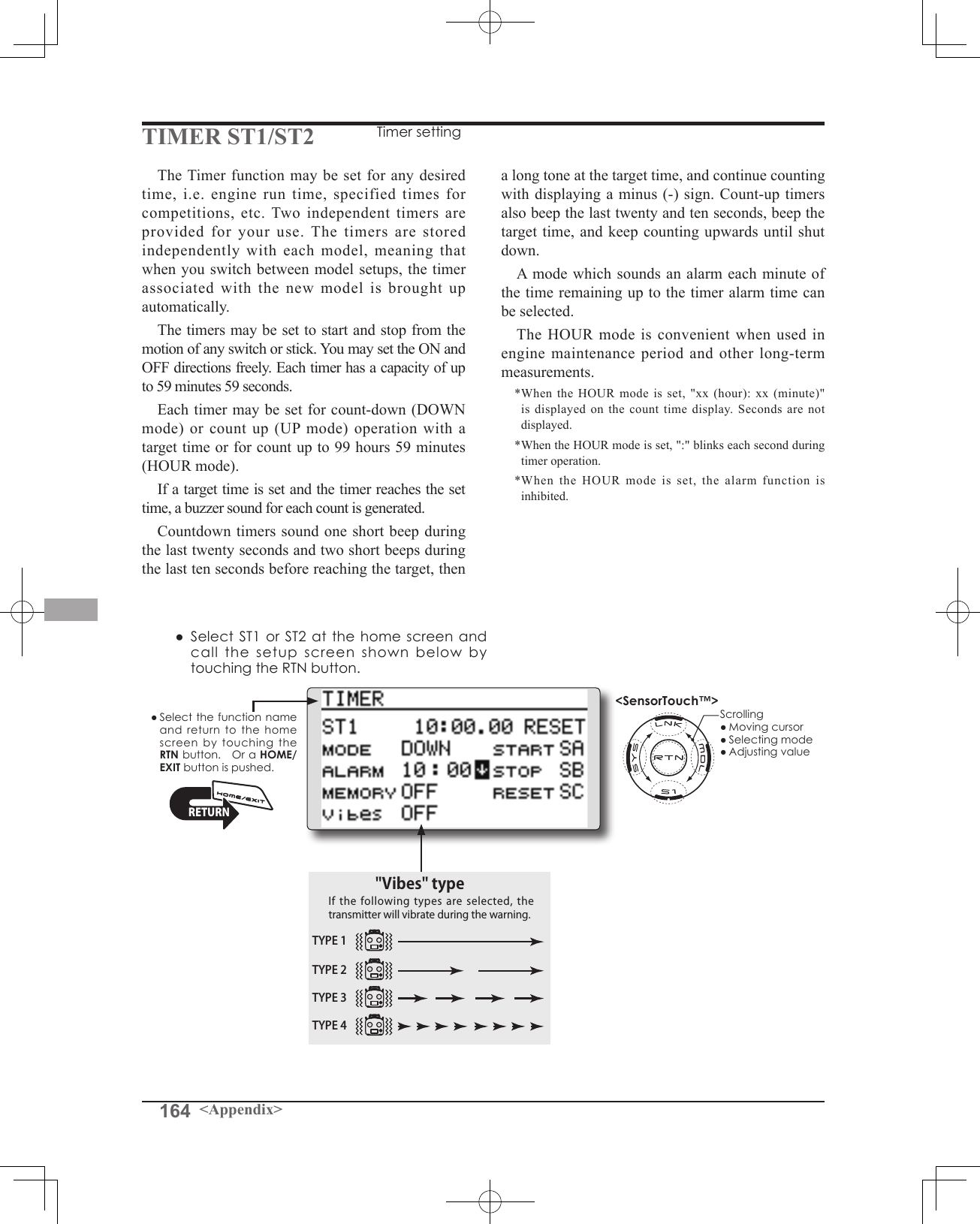
![165<Appendix>Timer setting●Up timer/down timer setting Movethecursortothe[MODE]itemandtouchtheRTNbuttontoswitchtothedatainputmode. SelectthemodebyscrollingthetouchsensorandtouchtheRTNbutton. [UP]:Uptimer [DOWN]:Downtimer [HOUR]:Hourmodetimer●Timer time setting Movethecursortothe[ALARM]itemandtouchtheRTNbuttontoswitchtothedatainputmode. Setthetimebyscrollingthetouchsensor. [00]:[00]:[min]:[sec] TouchtheRTNbuttontoendtheadjustmentandreturntothecursormode.●Switch setting Movethecursortotheitemoftheswitchyouwanttoset,accesstheswitchsetupscreenbytouchingtheRTNbutton.SelecttheswitchandONdirection.[For a detailed description of the setting method, see [Switch Setting Method] located on the next page.] [START]:Startswitch [STOP]:Stopswitch [RESET]:Resetswitch●Memory setting Movethecursortothe[MEMORY]itemandtouchtheRTNbuttontoswitchtothedatainputmode. SelectthemodebyscrollingthetouchsensorandtouchtheRTNbutton. [OFF]:MemoryfunctionOFF [ON]:Modewherethetimerisnotresetwhenturnedpoweroffandswitchedthemodel.●A mode which sounds an alarm each minute can be selected. Changethesettingusingthe""button(or""button)."":Alarmsoundseachminuteofthetimeelapsedfromtimerstart.(Conventionalmode)"":Alarmsoundseachminuteofthetimeremaininguptothealarmtime.Timer operation● TimerST1andST2arestarted/stoppedbypre-selectedstart/stopswitch.● Toresetatimer,operatethepre-selectedresetswitch,ormovethecursortothe[RESET]displayonthetimerscreenandtouchtheRTNbutton.](https://usermanual.wiki/Futaba/T14SG-24G.User-Manual-3/User-Guide-1894990-Page-85.png)
![166 <Appendix>The various functions used in the T14SG can be activated by a switch. For the purposes of this manual, a stick position, VR position, etc. shall be commonly referred to as a switch in all cases. That (Switchselectionscreenexample)When switch is selectedWhen switch was selected, ON/OFF position setting is also performed.*The ON/OFF setting state of each position is displayed.1.WhenyouwanttochangetheON/OFFsetting,usethetouchsensortomovethecursorandtouchtheRTNbuttontoswitchtothedatainputmode.SwitchtheON/Offdisplaybyscrollingthetouchsensor.*ON/OFF display blinks.2.WhentheRTNbuttonistouched,theON/OFFsettingischanged.(TouchtheS1buttontostopthechange.)3.Toreturntothepreceedingscreen,movethecursortothe[ON/OFF]atthetopofthescreenandtouchtheRTNbutton.When stick, trim lever, or knob selectedWhen a stick, trim lever, or knob is used as a switch, two operation modes can be selected:1.Whenyouwanttochangethemode,movethecursorto[MODE]itemandtouchtheRTNbuttontoswitchtothedatainputmode.SwitchthedisplaytothemodeyouwanttochangebyscrollingthetouchsensorandthenmakethechangebytouchingtheRTNbutton.●Mode:[LIN]/[SYM]*Set the ON/Off point by the method described on the next page.Switch selection1.Usethetouchsensortomovethecursor(highlights)totheswitchyouwanttoselectandtouchtheRTNbutton.*The switch blinks.2.Toreturntothepreceedingscreen,movethecursortothe[H/WSELECT]atthetopofthescreenandtouchtheRTNbutton. Or,movethecursortothe[ON/OFF]andcalltheON/OFFpositionsettingscreenbytouchingtheRTNbutton.Alternate mode setting ●ALTERNATEmode:[OFF]/[ON]1.Movethecursortothe[ALTERNATE]itemandtouchtheRTNbuttontoswitchtothedatainputmode.2.Changetothemodeyouwanttosetbyscrollingthetouchsensor.*The mode display blinks.3.TouchtheRTNbutton.(TouchtheS1buttontostopthechange.)4.Toreturntothepreceedingscreen,movethecursortothe[ON/OFF]atthetopofthescreenandtouchtheRTNbutton.Switch Setting MethodSwitch selectionWhen a switch is selected at a mixing function, etc., the selection screen shown below is called.is, whenever the manual indicates that something is operated via a switch, it is possible for the user to activate this setting via a stick, stick position, etc.](https://usermanual.wiki/Futaba/T14SG-24G.User-Manual-3/User-Guide-1894990-Page-86.png)
![167<Appendix>Operation modesThe operation modes available when stick, trim lever, or knob was selected are described below. Linear mode [LIN]This mode sets ON/OFF to the left or right (up or down) with the set point as the reference. Symmetrical mode [SYM]Left and right (up and down) operations are symmetrical near the neutral position. For instance, when you want to switch D/R with the aileron stick, when the stick is moved to the left or right, DR can be turned on at the same position.Shifting the ON/Off pointThe ON/OFF point can be shifted. ON/OFF at a free position can be changed.●Blackrange:OFFrange●Whiterange:ONrange[Setting method]1.First,usethetouchsensortomovethecursortothe[POS]item.2.Movethestick,trimlever,orknobtothepointyouwanttochangeandtouchtheRTNbutton.Thepointisshifted.3.Toreturntothepreceedingscreen,movethecursortothe[ON/OFF]atthetopofthescreenandtouchtheRTNbutton.](https://usermanual.wiki/Futaba/T14SG-24G.User-Manual-3/User-Guide-1894990-Page-87.png)
![168 <Appendix>FUTABA CORPORATION Phone: +81 475 32 6982, Facsimile: +81 475 32 69831080 Yabutsuka, Chosei-mura, Chosei-gun, Chiba-ken, 299-4395, Japan©FUTABA CORPORATION 2012, 10 (1)Logic mode AND:WhenbothswitchesareON,theconditionisON. OR:WheneitherswitchisON,theconditionisON. EX-OR:Whenthetwoswitchesareindifferentstates,theconditionisON.Switch mode selection1.Movethecursortothe[SINGLE]itemandtouchtheRTNbuttontoswitchtothedatainputmode.2.Selectthe[LOGIC]byscrollingthetouchsensor.*[LOGIC] display blinks.3.TouchtheRTNbuttontochangetothelogicswitchmode.(Logicswitchsettingscreen)Logic mode selection1.MovethecursortothelogicmodeitemandtouchtheRTNbuttontoswitchtothedatainputmode.2.Selectthelogicmodebyscrollingthetouchsensor.[AND,ORorEX-OR]*The mode display blinks.3.TouchtheRTNbuttontochangetothelogicmode.Swich selection1.Selecttherightandleftswitchrespectively.(Refertothedescriptionatthepreviouspage.) Toreturntothepreceedingscreen,movethecursortothe[SWITCH]atthetopofthescreenandtouchtheRTNbutton.Logic switch (Condition Select function only)The logic switch function lets you turn operation on and off by combining two switches.](https://usermanual.wiki/Futaba/T14SG-24G.User-Manual-3/User-Guide-1894990-Page-88.png)