Contents
- 1. User Manual 1
- 2. User Manual 2
- 3. User Manual 3
User Manual 3
81
<Functions of Linkage Menu>
● Select the function name
and return to the Linkage
menu by touching the
RTN button. Or the
HOME/EXIT button is
pushed.
<SensorTouch™>
RETURN
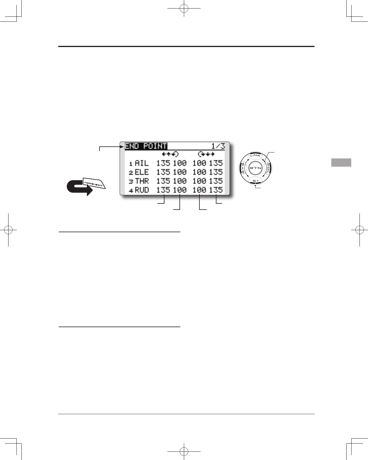
END POINT Sets the travel and limit point of each servo.
The End Point function adjusts the left and right
servo throws, generates differential throws, and
will correct improper linkage settings.
The travel rate can be varied from 0% to 140%
in each direction on channels 1 to 12(FASSTest
12CH mode). Also, the limit point where servo
throw stops may be varied from 0% to 155%.
Servo travel adjustment
1. Move the cursor to the travel icon of the
channel you want to adjust and touch the
RTN button to switch to the data input mode.
2. Ajust the rate by scrolling the touch sensor.
Initial value: 100%
Adjustment range: 0%~140%
*When the RTN button is touched for one second, the rate is
reset to the initial value.
Touch the RTN button to end adjustment and
return to the cursor mode.
3. Repeat this procedure for each rate.
Limit point adjustment
1. Move the cursor to the limit point icon of the
channel you want to adjust and touch the
RTN button to switch to the data input mode.
2. Ajust the limit point by scrolling the touch
sensor.
Initial value: 135%
Adjustment range: 0%~155%
*When the RTN button is touched for one second, the limit
point is reset to the initial value.
Touch the RTN button to end adjustment and
return to the cursor mode.
3. Repeat this procedure for each limit point.
● Select [END POINT] in the Linkage menu and
access the setup screen shown below by touching
the RTN button.
(The display screen is an example. The
screen depends on the model type.)
Scrolling
● Moving cursor
● Adjusting value
● To next page
(limit point)
(travel)
(limit point)
(travel)
82 <Functions of Linkage Menu>
● Select the function name
and return to the Linkage
menu by touching the
RTN button. Or the
HOME/EXIT button is
pushed.
<SensorTouch™>
RETURN
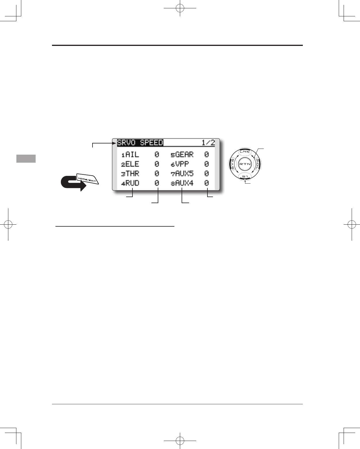
SERVO SPEED Sets the speed of each servo.
The speed of the servo from 1CH to 12CH of
operation can be set up.
It can adjust to 0-27.
Speed becomes slow as a numerical value's 0
increases in the state of the fastest of the servo.
* Speed cannot be made quicker than the maximal rate of the
servo to be used.
Servo speed setting
1. Touch the Speed button of the channel you
want to set.
2. Use the adjustment buttons to adjust the
servo speed.
●Initial value: 0
●Adjustment range: 0~27 (steps)
*When the RTN button is touched for one second, the rate is
reset to the initial value.
3. Repeat this procedure for each channel.
* It will overlap, if speed control of a S.BUS servo setup is
used at the time of S.BUS servo use, and speed changes.
Please use one either.
* The speed of THR is not set up simultaneously with THR
DELAY (model menu : only airplane).
● Select [SERVO SPEED] in the Linkage menu and
access the setup screen shown below by touching
the RTN button.
(The display screen is an example. The
screen depends on the model type.)
Scrolling
● Moving cursor
● Adjusting value
● To next page
(channel)
(speed)
(speed)
(channel)
83
<Functions of Linkage Menu>
● Select the function name
and return to the Linkage
menu by touching the
RTN button. Or the
HOME/EXIT button is
pushed.
<SensorTouch™>
RETURN
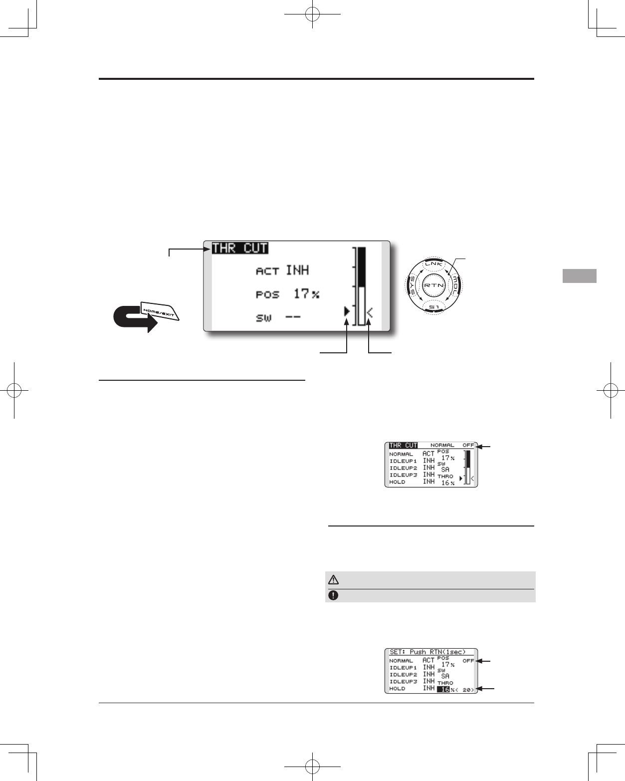
THR CUT Stops the engine safely and easily.(airplane and helicopter only)
Throttle cut provides an easy way to stop the
engine. Generally speaking, modelers will do so
by ipping a switch with the throttle stick at idle.
The action is not functional at high throttle to
avoid accidental dead stick landings. The switch’s
location and direction must be chosen, as it defaults
to NULL.
Individually adjust the Throttle Cut activation
setting for each condition. (helicopter)
Throttle cut setting procedure
1. Activate the function:
Move the cursor to the [ACT] item and touch
the RTN button to switch to the data input
mode.
Select the ACT mode by scrolling the touch
sensor.
*The display blinks.
Touch the RTN button to activate the
function and return to the cursor mode.
2. Switch selection:
Move the cursor to the [SW] item and access
the switch setup screen by touching the
RTN button and select the switch and ON
direction.
*For a detailed description of the setting method, see [Switch
Setting Method] at the back of this manual.
3. Throttle cut position setting:
Move the cursor to the [POS] item and touch
the RTN button to switch to the data input
mode.
Adjust the servo operation position at throttle
cut operation by scrolling the touch sensor.
Initial value: 17%
Adjustment range: 0%~50%
*When the RTN button is touched for one second, the servo
operation position is reset to the initial value.)
Touch the RTN button to end the adjustment
and return to the cursor mode.
*With the selected cut switch ON and the throttle stick at idle;
adjust the rate until the engine consistently cuts off.
However, be sure that the throttle linkage is not pulled too
tight or unreasonable force is not applied to the servo.
Designating a Throttle Cut setting position.
(helicopter)
*A throttle cut function acts in the low side of the throttle
position.
*"THRO" setting is common with all condition.
Warning
Normal setting is slightly above idle.
1. To add the Throttle Cut position, use the
cursor to select the THRO percentage
desired, then press and hold the RTN button
for one second.
*Since conditions are not offered when an Airplane is selected,
the Throttle Cut options will vary from the options noted
below.
*The Throttle Cut POS and SW settings are utilized for all
conditions.
*If the Throttle Cut switch is activated, or on, this status will
continue even if the condition is changed to an inhibited
setting.
*If the condition is inhibited (INH) the Throttle Cut is off if
the SW is in the off position and the throttle stick is low.
● Select [THR CUT] in the Linkage menu and access
the setup screen shown below by touching the
RTN button.
● Current throttle position
● Individually adjust the Throttle Cut activation
setting for each condition. (helicopter)
● Cut position
Scrolling
● Moving cursor
● Selecting mode
● Adjusting value
● Throttle
cut status
● Throttle
cut status
● Throttle
stick position
84 <Functions of Linkage Menu>
● Select the function name
and return to the Linkage
menu by touching the
RTN button. Or the
HOME/EXIT button is
pushed.
<SensorTouch™>
RETURN
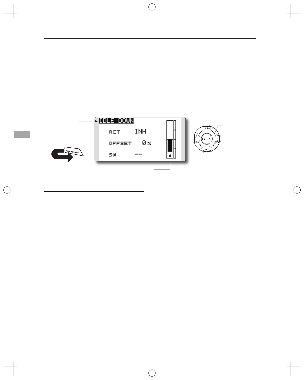
IDLE DOWN Lowers the engine idling speed.(airplane only)
The Idle Down function lowers the engine to
its idle position. Like Throttle Cut, this is usually
accomplished by ipping a switch with the throttle
stick at idle. The action is not functional at high
throttle to avoid accidental dead sticks. The
switch’s location and direction must be chosen, as
it defaults to NULL.
Idle down setting procedure
1. Activate the function:
Move the cursor to the [ACT] item and touch
the RTN button to switch to the data input
mode.
Select the ACT mode by scrolling the touch
sensor.
*The display blinks.
Touch the RTN button to activate the
function and return to the cursor mode.
2. Switch selection:
Move the cursor to the [SW] item and access
the switch setup screen by touching the RTN
button. Select the switch and ON direction.
*For a detailed description of the setting method, see [Switch
Setting Method] at the back of this manual.
3. Offset rate setting:
Move the cursor to the [OFFSET] item and
touch the RTN button to switch to the data
input mode.
Adjust the servo offset rate at idle down
operation by scrolling the touch sensor.
Initial value: 0%
Adjustment range: -100%~0%~+100%
* When a minus rate is input, an offset is applied at the high
side.
*Maximum offset amount is near maximum slow.
* When the RTN button is touched for one second, the offset
rate is reset to the initial value.
Touch the RTN button to end the adjustment
and return to the cursor mode.
● Select [IDLE DOWN] in the Linkage menu and
access the setup screen shown below by touching
the RTN button.
Scrolling
● Moving cursor
● Selecting mode
● Adjusting value
● Current throttle position
85
<Functions of Linkage Menu>
● Select the function name
and return to the Linkage
menu by touching the
RTN button. Or the
HOME/EXIT button is
pushed.
<SensorTouch™>
RETURN
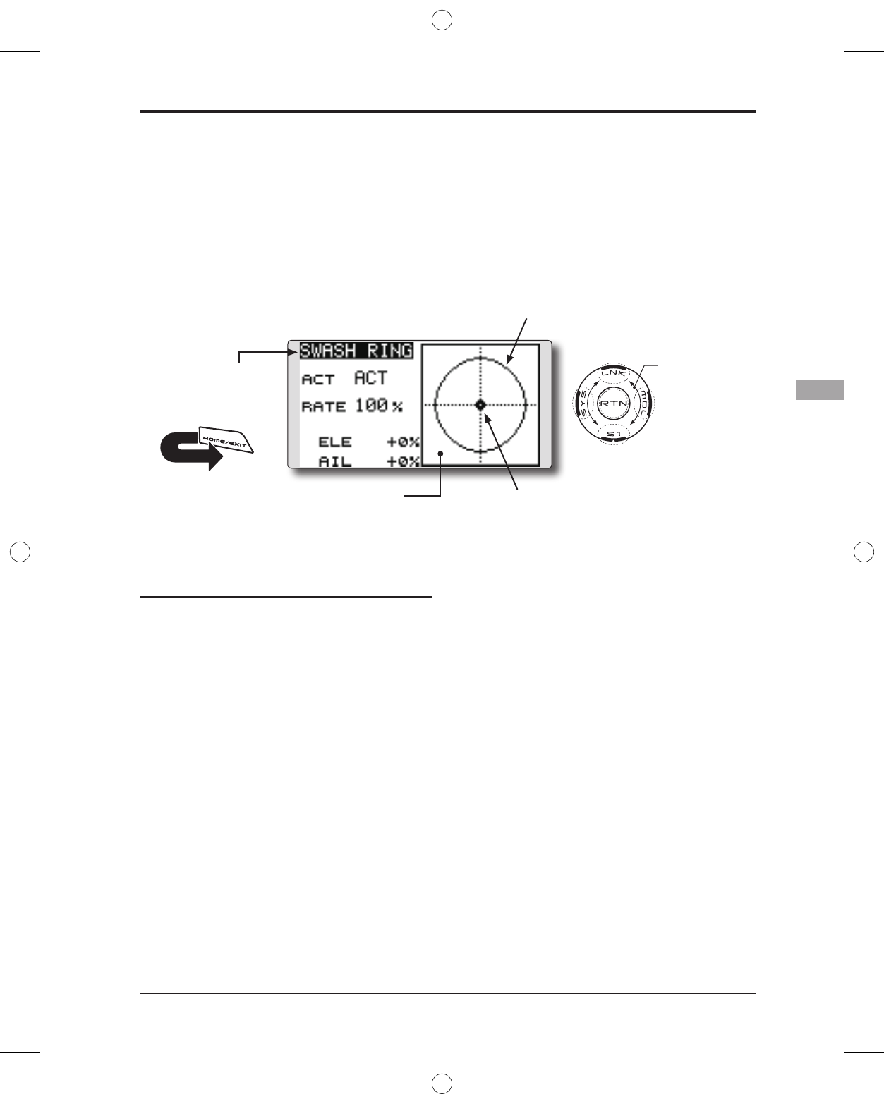
SWASH RING
Swash ring setting procedure
1. Activate the function:
Move the cursor to the [ACT] item and touch
the RTN button to switch to the data input
mode.
Select the ACT mode by scrolling the touch
sensor.
*The display blinks.
Touch the RTN button to activate the
function and return to the cursor mode.
2. Rate setting:
Move the cursor to the [RATE] item touch the
RTN button to switch to the data input mode.
Set the rate by scrolling the touch sensor.
Initial value: 100%.
Adjustment range: 50 to 200%.
*Adjust the rate to maximum swash tilt.
*When the RTN button is touched for one second, the rate is
reset to the initial value.
Touch the RTN button to end adjustment and
return to the cursor mode.
Limits the swash plate travel to within a xed range. (Helicopter only)
This function limits the swash travel to a fixed
range in order to prevent damaging the swash
linkage by simultaneous operation of the ailerons
and elevators. It is very useful in 3D aerobatics
which use a large travel.
● The operating range display area:
The vertical direction shows the
elevator travel. The horizontal
direction shows the aileron travel.
● The marker shows the
stick position.
● Select [SWASH RING] in the Linkage
menu and access the setup screen
shown below by touching the RTN
button.
● When the swash ring function is activated,
a circle is displayed in the operating
range display area and the rate input box
is displayed. Stick operation is limited to
the area of this circle.
Scrolling
● Moving cursor
● Selecting mode
● Adjusting value
86 <Functions of Linkage Menu>
● Select the function name
and return to the Linkage
menu by touching the
RTN button. Or the
HOME/EXIT button is
pushed.
<SensorTouch™>
RETURN
SWASH Swash AFR and linkage correction function. (helicopter only, except
swash type H-1)
Neutral Point
At your linkages, if the servo horn deviates from
a perpendicular position at neutral, the linkage
compensation functions in this menu may not
compensate effectively. To correct this use the
Neutral Point function. This will move the neutral
point of the servos to the actual perpendicular
position. However, this adjustment changes only
the axis point of the compensation functions in this
menu, and does not affect the neutral position of
other functions.
Swash AFR
Swash AFR function reduces, increases, or
reverses the rate (travel) of the aileron, elevator and
collective pitch functions, by adjusting or reversing
the motion of all servos involved in that function,
only when using that function.
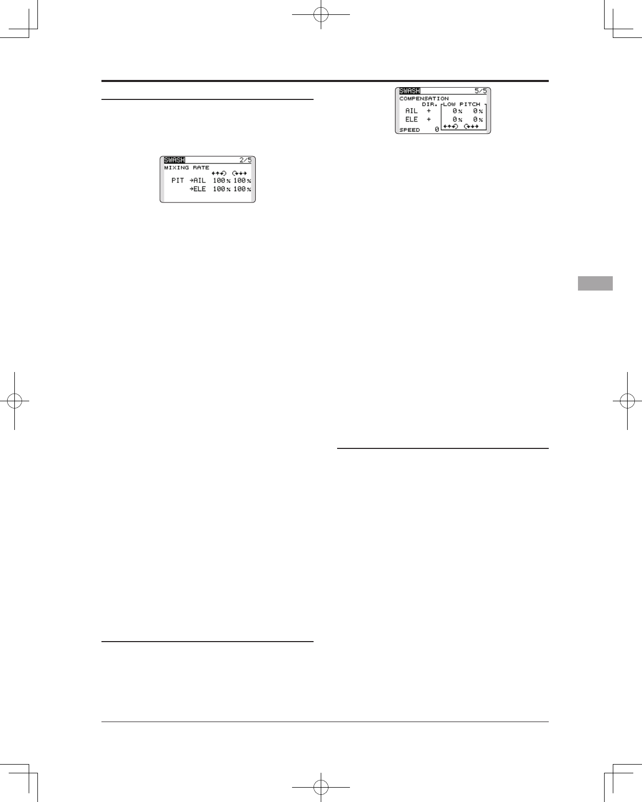
Mixing Rate
This mixing is used to compensate the swash-
plate as necessary during specific control inputs.
Neutral point setting procedure
The neutral point becomes the correction
standard point.
*Adjusting the servo horn so that the neutral point is near the
50% position makes the mixing amount small.
1. Neutral point setting
Move the cursor to the [POS] item and hold
the pitch operation so that the servo horn is
at a right angle to the linkage rod and Touch
the RTN button for one second. This value
indicates the servo's neutral position.
After reading the neutral point, use the
other correction functions to make further
adjustments.
The following compensation mixing is possible;
PIT to AIL, PIT to ELE, AIL to PIT, ELE to AIL,
and ELE to PIT (HR3 mode.) It adjusts the swash-
plate to for proper operation of each control using
the corresponding compensation mixing.
Linkage Compensation
This compensation mixing is used to correct the
swash-plate for pitch control at low pitch and high
pitch.
Speed Compensation
This function is used to cancel the reaction that
is generated by the difference in the movements of
each servo when the swash-plate moves.
Subtrim
Subtrim for aileron, elevator and pitch can be set
during swash setting.
Pitch adjustment function
High, neutral and low pitch xed outputs can be
used while adjusting the pitch.
Swash AFR setting procedure
The swash AFR function makes adjustments so
that the servos travel the specied amount by [AIL],
[ELE], and [PIT] operation.
1. Move the cursor to the function you want to
adjust and touch the RTN button to switch to
the data input mode.
2. Adjust the AFR rate by scrolling the touch
sensor.
Initial value: +50%
Adjustment range: -100%~+100%
*When the RTN button is touched for one second, the AFR
rate is reset to the initial value.
Touch the RTN button to end adjustment and
return to the cursor mode.
● Select [SWASH] in the Linkage menu and access
the setup screen shown below by touching the
RTN button.
Scrolling
● Moving cursor
● Selecting mode
● Adjusting value
● To next page
87
<Functions of Linkage Menu>
Mixing rate setting procedure
The HR3 swash-plate type will be used as an
example to describe mixing rate setting. The mixing
used in other swash modes may be different,
however, the setting procedure is the same.
*Set the throttle stick to the preset neutral point. Adjust the
length of the linkage rod so that the swash plate is horizontal
at this position.
*The sub-trim function can be used to make small
adjustments.
*Adjust so that the pitch curve is a straight line and the
helicopter achieves maximum pitch.
*Move the cursor to the item you want to adjust and touch
the RTN button to switch to the data input mode. Touch
the RTN button to end adjustment and return to the cursor
mode.
1. Adjusting the aileron operation [AIL to PIT]
Adjust the AIL to PIT rate so there is no binding
in the elevator or pitch movement when the
aileron stick is moved to the left and right.
*Adjust by scrolling the touch sensor.
*The left and right sides can be adjusted individually.
2. Adjusting the elevator operation [ELE to AIL]/
[ELE to PIT]
Adjust the ELE to AIL and ELE to PIT rates so
there is no binding in the aileron or pitch
movement when the elevator stick is moved
up and down.
*Adjust by scrolling the touch sensor.
*The up and down sides can be adjusted individually.
3. Adjusting the pitch operation [PIT to AIL][PIT
to ELE]
Adjust the PIT to AIL and PIT to ELE rates so
that the swash plate moves to the level/
horizontal position when the throttle stick was
moved to maximum low and full high.
*Adjust by scrolling the touch sensor.
*The slow and high sides can be adjusted individually.
Linkage compensation setting procedure
*Prior to utilizing the linkage compensation settings, it is
important to adjust the mixing rate settings.
*Linkage compensation overrides interference from the
aileron operation with the elevator or elevator operation
with the aileron at collective pitch control for low pitch and
high pitch.
*When making the following setting, Move the cursor to the
item you want to set and touch the RTN button to switch
to the data input mode. Touch the RTN button to end
adjustment and return to the cursor mode.
1. Compensating aileron input [AIL]
Set the throttle to the lowest position. Move
the aileron stick to the left and right and
adjust the aileron compensation amount
so that interference in the elevator or pitch
direction is minimal.
*Adjust by scrolling the touch sensor.
*The left and right sides can be adjusted individually.
*If the interference increases when the compensation amount
was increased, make adjustments with the direction [DIR.]
using the plus "+" or minus "-".
2. Compensating elevator input [ELE]
Adjust the elevator compensation amount
so that the aileron or pitch direction
interference when the elevator stick was
moved up and down is minimal.
3. Repeat steps 1 and 2 above, perform aileron
and elevator compensation similarly at full
throttle.
Speed compensation setting procedure
1. Move the cursor to the "SPEED" item and
touch the RTN button to switch to the data
input mode.
2. Set the throttle stick to the neutral point
position. Quickly move the elevator stick and
adjust the speed compensation amount
[SPEED] for minimum interference in the pitch
direction.
*Adjust by scrolling the touch sensor.
Touch the RTN button to end adjustment and
return to the cursor mode.
88 <Functions of Linkage Menu>
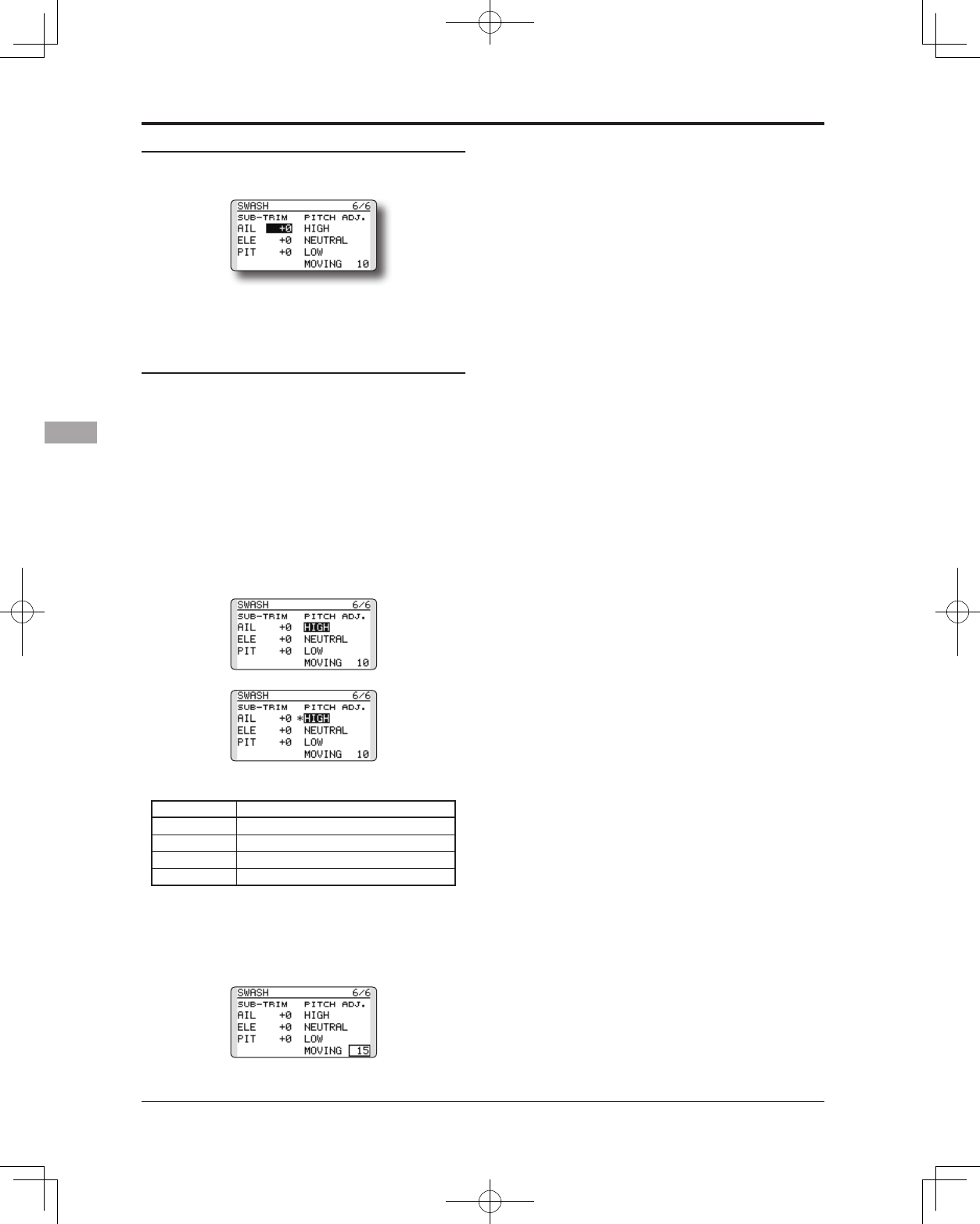
Subtrim setting procedure
Subtrim can be set on the last page of the swash
setting screen.
*The sub-trim value set here is reflected at sub-trim of the
linkage menu.
Pitch adjustment procedure
The pitch adjustment function can be used on the
last page of the swash setting screen.
1. Call the last page of the swash setting
screen.
2. When the cursor is moved to a pitch
adjustment button and the RTN button is
touched, the corresponding pitch is output.
* In the pitch adjustment mode an * is displayed at the left
side of the current output setting button.
*If the cursor is moved to another button and the RTN button
is touched during pitch adjustment, the pitch adjustment
mode is deactivated.
Function details are as follows:
Button Function
High High pitch xed output mode
Neutral Neutral pitch xed output mode
Low Low pitch xed output mode
Moving Cyclic pitch output mode
*The cyclic pitch speed can be set with the button at the right
side of the “Moving” button.
Setting range: 1 to 100
*When the set value is large, motion becomes fast and when
the set value is small, motion becomes slow.
89
<Functions of Linkage Menu>
● Select the function name
and return to the Linkage
menu by touching the
RTN button. Or the
HOME/EXIT button is
pushed.
<SensorTouch™>
RETURN
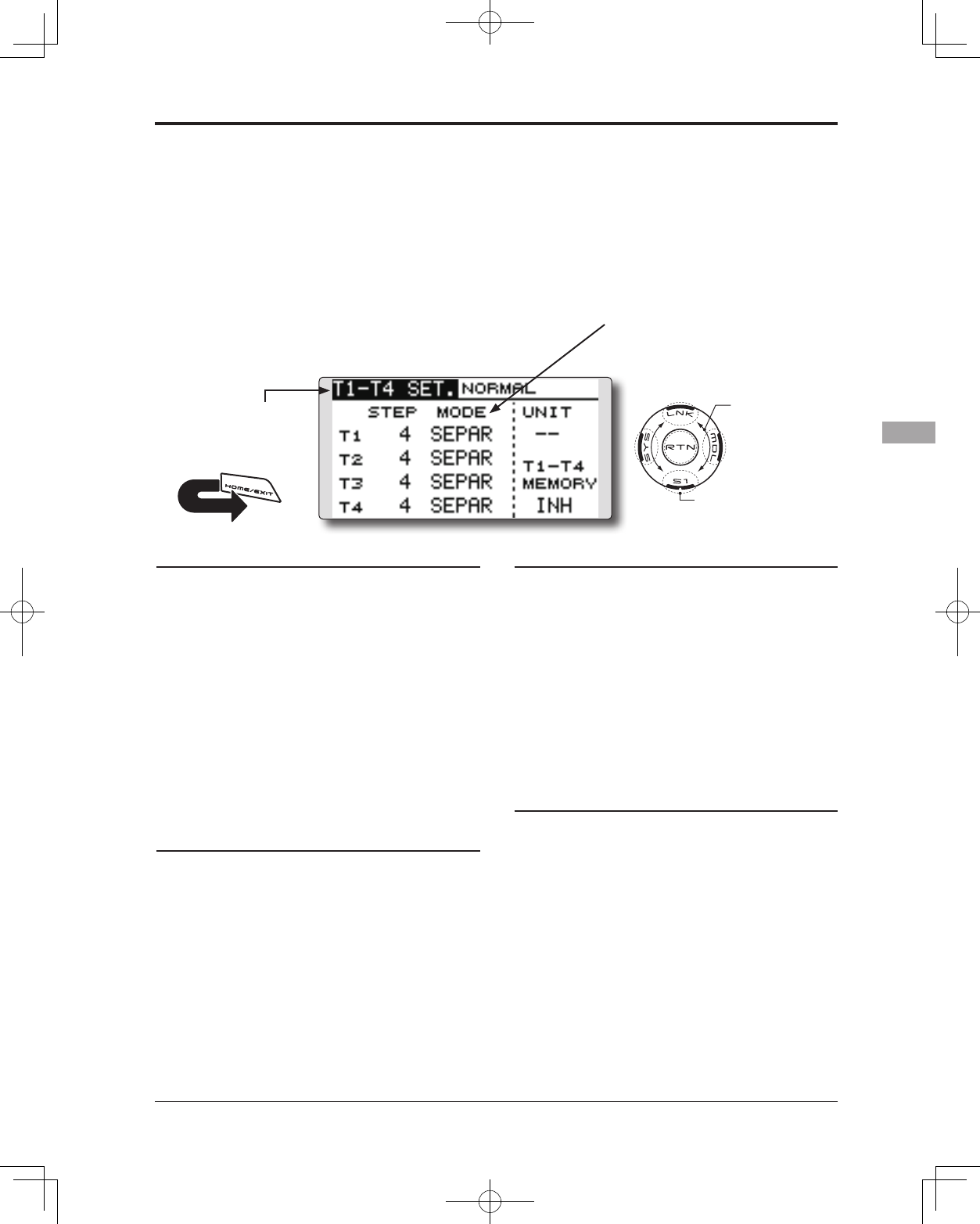
T1-T4 SET. Digital trim settings
This function adjusts the digital trim's step
amount and operation mode (T1~T4.)
When the flight conditions are set, the trim
operation can be coupled with the conditions when
combination mode is selected.
The T14SG unit of trim is displayed on the home
screen.
Control step amount setting
1. Move the cursor to the [STEP] item and touch
the RTN button to switch to the data input
mode.
2. Set the control step amount by scrolling the
touch sensor.
Initial value: 4
Adjustment range: 0~200
*When the RTN button is touched for one second, the control
step amount is reset to the initial value.
*When the value is increased, the change per step becomes
larger.
3. Touch the RTN button to end adjustment and
return to the cursor mode.
Separate/combination mode selection (Heli and
Glider only)
1. Move the cursor to the [MODE] item and
touch the RTN button to switch to the data
input mode.
2. Select the mode by scrolling the touch
sensor. A conrmation message appears.
*The display blinks.
[COMB.]: Combination mode. The trim's data
is reected in all ight conditions.
[SEPAR]: Separate mode. Trim adjustments
are made individually for each flight
condition.
3. Touch the RTN button. (To terminate the input
and return to the original state, touch the S1
button.)
Display unit selection
1. Move the cursor to the [UNIT] item and
touch the RTN button to switch to the data
input mode.
2. Select the mode by scrolling the touch
sensor. A conrmation message appears.
*The display blinks.
[--]: A step number is displayed on the home
screen. There is no unit display.
[ %]: "%" is displayed as a unit.
3. Touch the RTN button. (To terminate the input
and return to the original state, touch the S1
button.)
Trim Memory Operation procedure
1. Move the cursor to the [T1-T4 MEMORY] item
and touch the RTN button to switch to the
data input mode.
2. Select the ACT mode by scrolling the touch
sensor. A conrmation message appears.
[INH]: Inhibited
[ACT]: Activated
3. Touch the RTN button. (To terminate the input
and return to the original state, touch the S1
button.)
4. At the home screen, move the cursor to the
trim you want to change and touch the RTN
for one second. The trim display is moved to
the center position.
*When the function is inhibited, the trim position returns to
the actual trim position.
Only the trim displayed on the home screen can
be moved to the center position without changing
the actual trim's memory position.
● Select [T1-T4 SET.] in the Linkage menu and access
the setup screen shown below by touching the
RTN button.
(The display screen is an example. The
screen depends on the model type.)
● Trim operation mode
"COMB.": Combination mode
"SEPAR": Separate mode
Scrolling
● Moving cursor
● Selecting mode
● Adjusting value
● To next page
*The display blinks.
90 <Functions of Linkage Menu>
● Select the function name
and return to the Linkage
menu by touching the
RTN button. Or the
HOME/EXIT button is
pushed.
<SensorTouch™>
RETURN
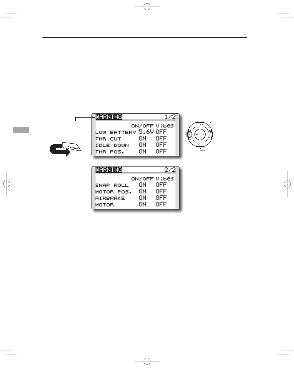
WARNING Low Battery alarm voltage set Warning normal reset
The T14SG includes an audible alarm that
sounds when the transmitter’s battery voltage drops
below a pre-determined setting; adjustable for cell
types and voltages.
Mixing warning at power ON can be reset to
OFF.
Accessing and Activating the Low Battery
Alarm
1. The Low Battery (LOW BATTERY) alarm
voltage is accessed through the T14SG’s
System Menu. Within the System Menu, use
the SensorTouch™ to highlight the SOUND
option and then press the Return (RTN)
button to conrm the selection.
2. Use the SensorTouch to scroll to the Low
Battery (LOW BATTERY) alarm, and then press
the Return (RTN) button to access the voltage
settings. Using the SensorTouch, adjust the
voltage as desired and/or determined by
the transmitter battery pack being utilized.
The voltage options range from 5.0V to 6.0V.
Suggested voltage settings are as follows:
5-Cell NiCd or NiMH: 5.6V
2-Cell LiFe: 6.0V
Warning normally resetting method
1. Move the cursor to the item you want to
reset to OFF and touch the RTN button to
switch to the data input mode.
2. Select the OFF mode by scrolling the touch
sensor.
*The display blinks.
3. Touch the RTN button. (To terminate the input
and return to the original state, touch the S1
button.)
Warning display:
Airplane: Throttle cut/Idle down/Throttle
position/Snap-roll/Motor position/Airbrake/
Motor
Helicopter: Condition/Throttle cut/Throttle
position/Throttle Hold
Glider: Condition/Motor position/Trim-mix/Motor
● Select [WARNING] in the Linkage menu and
access the setup screen shown below by touching
the RTN button.
● Push S1 button to advance to next page.
Scrolling
● Moving cursor
● Selecting mode
● Adjusting value
● To next page
*About low battery voltage, all the models included in one
transmitter are changed in common. It cannot set to different
voltage for every model. Moreover, data reset is not carried
out.
91
<Functions of Linkage Menu>
● Select the function name
and return to the Linkage
menu by touching the
RTN button. Or the
HOME/EXIT button is
pushed.
<SensorTouch™>
RETURN
TELEMETRY Displaying data from the receiver
This screen displays your choice of data from the
receiver.
Also warnings can be activated regarding
other data from your aircraft. For example, if the
receiver voltage drops, the user can be warned by
an alarm (and vibration).
*It cannot be used in FASST mode and S-FHSS mode.
*Only receiver voltage and EXT voltage can be used in
FASSTest12CH mode.
*The FASSTest14CH mode can use all the telemetry functions.
● Select [TELEMETRY] in the Linkage menu and
access the setup screen shown below by touching
the RTN button.
● Push S1 button to advance to next page.
● [TELEMETRY] can be called if the HOME/EXIT button
is pushed from a home screen.
Scrolling
● Moving cursor
● Selecting mode
● Adjusting value
● To next page
● Receiver -> Transmitter. The
reception strength is shown.
How to see telemetry date
1. Telemetry screen can be called if the HOME/
EXIT button is pushed from the home screen.
Or select [TELEMETRY] in the Linkage menu
and access the setup screen by touching
the RTN button.
2. If each item is chosen and the RTN button is
pushed, an alarm setup can be performed
with the minimum/maximum after a
transmitter is turned on.
*Receiver voltage can be checked immediately. An optional
sensor will need to be attached to S.BUS2 of a receiver if
you would like to see other information.
*No special setup is necessary if each sensor displayed
is left as in the default setup. Separate sensor ID
is also unnecessary. However, if two or more of
one kind of sensor is used, setup is required in the
"SENSOR" menu.
Warning
Do not watch the transmitter screen during
ight.
*You may loose sight of the aircraft during ight and this is
extremely dangerous. Have an assistant on hand to check
the screen for you. A pilot should NEVER take his eyes off
his aircraft.

92 <Functions of Linkage Menu>
● Select the function name
and return to the Linkage
menu by touching the
RTN button. Or the
HOME/EXIT button is
pushed.
<SensorTouch™>
RETURN
TELEMETRY : Rx-BATT. Displaying data from the receiver battery voltage
In this screen, the battery voltage of a receiver is
displayed.
If it becomes higher or lower than the setting an
alarm and/or vibration will alert you.
*It cannot be used in FASST mode and S-FHSS mode.
*Only receiver voltage and EXT voltage can be used in
FASSTest12CH mode.
*The FASSTest14CH mode can use all the telemetry functions.
● Select [Rx-BATT.] in the TELEMETRY screen and
access the setup screen shown below by touching
the RTN button.
Scrolling
● Moving cursor
● Selecting mode
● Adjusting value
● To next page
● Receiver battery voltage
● The maximum and the minimum when
powering ON are shown.
● ↓The "down" arrow will
indicate that an alarm will
sound when the voltage
drops to below the setting.
Alert set
1. Move the cursor to the ↓ALERT [INH] item and
touch the RTN button to switch to the data
input mode.
2. Select the ACT mode by scrolling the touch
sensor.
3. Touch the RTN button. (To terminate the input
and return to the original state, touch the S1
button.)
4. Move the cursor to the ↓THRESHOLD [4.0V]
item and touch the RTN button to switch to
the data input mode.
5. Ajust the rate by scrolling the touch sensor.
Initial value: 4.0V
Adjustment range: 0.0V~8.4V
*When the RTN button is touched for one second, the rate is
reset to the initial value.
6. Touch the RTN button. (To terminate the input
and return to the original state, touch the S1
button.)
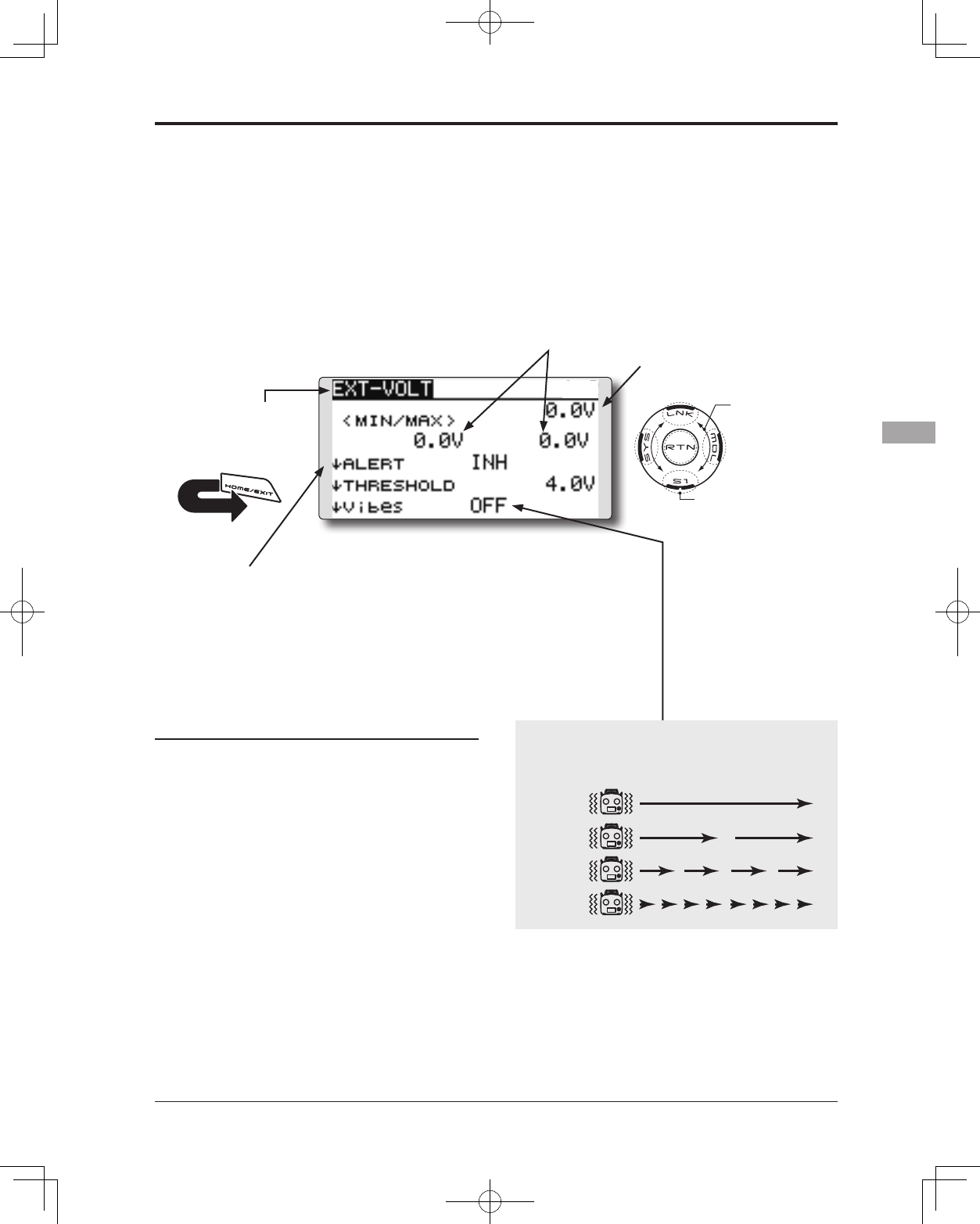
TYPE 1
TYPE 2
TYPE 3
TYPE 4
"Vibes" type
If the following types are selected, the transmitter will
vibrate during the warning.
93
<Functions of Linkage Menu>
● Select the function name
and return to the Linkage
menu by touching the
RTN button. Or the
HOME/EXIT button is
pushed.
<SensorTouch™>
RETURN
TELEMETRY : EXT-VOLT Displaying data from the EXT battery voltage port
The EXT-VOLT screen will display the data
from the EXT-battery output from the R7008SB
receiver. In order to use this function, it is necessary
to connect External voltage connector of the
R7008SB receiver to a CA-RVIN-700 (FUTM5551)
or SBS-01V to the battery you desire to measure
the voltage of.
You will be alerted by an alarm or vibration if
the voltage set by you is exceeded.
*It cannot be used in FASST mode and S-FHSS mode.
*Only receiver voltage and EXT voltage will be received in
the FASSTest12CH mode.
*The FASSTest14CH mode will display all telemetry data.
● Select [EXT-VOLT] in the TELEMETRY screen and
access the setup screen shown below by touching
the RTN button.
Scrolling
● Moving cursor
● Selecting mode
● Adjusting value
● To next page
● EXT battery voltage
● The maximum and the minimum when
powering ON are shown.
● ↓The arrow will indicate that
an alarm will sound when
the voltage drops to below
the setting.
Alert set
1. Move the cursor to the ↓ALERT [INH] item and
touch the RTN button to switch to the data
input mode.
2. Select the ACT mode by scrolling the touch
sensor.
3. Touch the RTN button. (To terminate the input
and return to the original state, touch the S1
button.)
4. Move the cursor to the ↓THRESHOLD [4.0V]
item and touch the RTN button to switch to
the data input mode.
5. Ajust the rate by scrolling the touch sensor.
Initial value: 4.0V
Adjustment range: 0.0V~100.0V
*When the RTN button is touched for one second, the rate is
reset to the initial value.
6. Touch the RTN button. (To terminate the input
and return to the original state, touch the S1
button.)
TYPE 1
TYPE 2
TYPE 3
TYPE 4
"Vibes" type
If the following types are selected, the transmitter will
vibrate during the warning.
*CA-RVIN-700 or SBS-01V must be installed in the aircraft.
94 <Functions of Linkage Menu>
● Select the function name
and return to the Linkage
menu by touching the
RTN button. Or the
HOME/EXIT button is
pushed.
<SensorTouch™>
RETURN
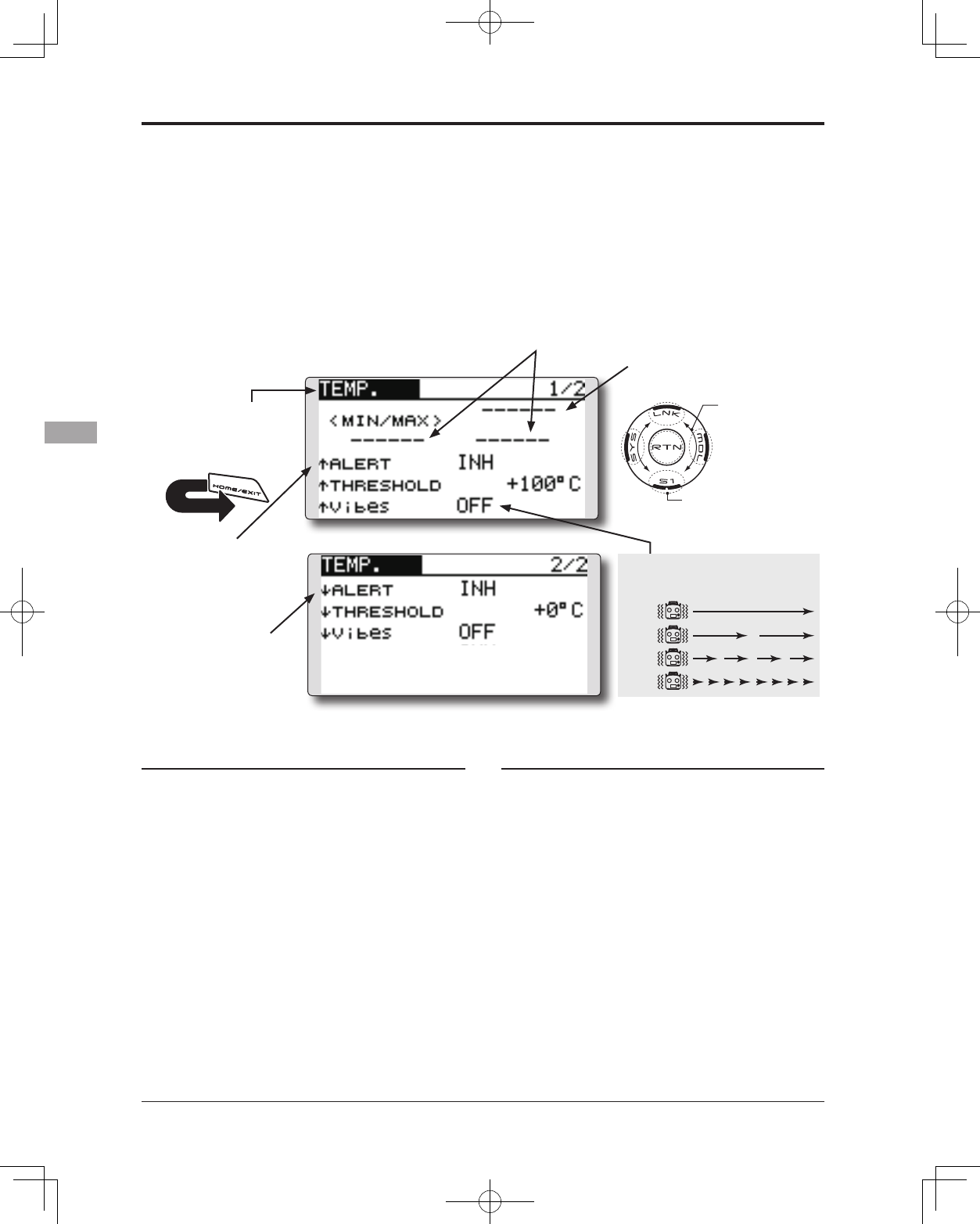
TELEMETRY : TEMP. Displaying data from the temperature
TEMP. is a screen which displays/sets up
the temperature information from an optional
temperature sensor.
The temperature of the model (engine, motor,
battery etc.) which is ying can be displayed.
If it becomes higher or lower than the setting an
alarm and/or vibration will alert you.
*It cannot be used in FASST mode and S-FHSS mode.
*Only receiver voltage and EXT voltage can be used in
FASSTest12CH mode.
*The FASSTest14CH mode can use all the telemetry functions.
● Select [TEMP.] in the TELEMETRY screen and access
the setup screen shown below by touching the
RTN button.
●Press the S1 button to advance to the next page.
Scrolling
● Moving cursor
● Selecting mode
● Adjusting value
● To next page
● Temperature
● The maximum and the minimum when
powering ON are shown.
● ↓ An downward arrow
will show that an alarm
will sound when the
temperature drops
below the set value.
● ↑ An upward arrow will
show that an alarm
will sound when the
temperature rises above
the set value.
Alert set : Hot warning
1. Move the cursor to the ↑ALERT item and
touch the RTN button to switch to the data
input mode.
2. Select the ACT mode by scrolling the touch
sensor.
3. Touch the RTN button. (To terminate the input
and return to the original state, touch the S1
button.)
4. Move the cursor to the ↑THRESHOLD [+100℃]
item and touch the RTN button to switch to
the data input mode.
5. Ajust the rate by scrolling the touch sensor.
Initial value: +100℃
Adjustment range: 1℃~200℃
(↑THRESHOLD > ↓THRESHOLD)
*When the RTN button is touched for one second, the rate is
reset to the initial value.
6. Touch the RTN button. (To terminate the input
and return to the original state, touch the S1
button.)
Alert set : Low-temperature warning
1. 2/2 page is accessed by pushing S1. Move
the cursor to the ↓ALERT item and touch the
RTN button to switch to the data input mode.
2. Select the ACT mode by scrolling the touch
sensor.
3. Touch the RTN button. (To terminate the input
and return to the original state, touch the S1
button.)
4. Move the cursor to the ↓THRESHOLD [+0 ℃]
item and touch the RTN button to switch to
the data input mode.
5. Ajust the rate by scrolling the touch sensor.
Initial value: +0℃
Adjustment range: 0℃~199℃
(↑THRESHOLD > ↓THRESHOLD)
*When the RTN button is touched for one second, the rate is
reset to the initial value.
6. Touch the RTN button. (To terminate the input
and return to the original state, touch the S1
button.)
TYPE 1
TYPE 2
TYPE 3
TYPE 4
"Vibes" type
If the following types are selected, the
transmitter will vibrate during the warning.
*A temperature sensor must be installed in the aircraft.
95
<Functions of Linkage Menu>
● Select the function name
and return to the Linkage
menu by touching the
RTN button. Or the
HOME/EXIT button is
pushed.
<SensorTouch™>
RETURN
TELEMETRY : RPM Displaying data from the RPM
RPM is a screen which displays / sets up the
RPM information from an optional RPM sensor.
The RPM of the model (engine, motor, etc.)
which is ying can be shown.
If it becomes higher or lower than the setting an
alarm and/or vibration will alert you.
*It cannot be used in FASST mode and S-FHSS mode.
*Only receiver voltage and EXT voltage can be used in
FASSTest12CH mode.
*The FASSTest14CH mode can use all the telemetry functions.
● Select [RPM] in the TELEMETRY screen
and access the setup screen shown
below by touching the RTN button.
●Press the S1 button to advance to the next page.
Scrolling
● Moving cursor
● Selecting mode
● Adjusting value
● To next page
● RPM
● The maximum and the minimum when
powering ON are shown.
●"MAGNETIC" or "OPTICAL"
is set according to the
sensor you use.
SBS-01RM : MAGNETIC
SBS-01RO : OPTICAL
● ↓An downward arrow
indicates that the
alarm will sound
when the RPM falls
below the set value.
● ↑An upward arrow
indicates that the
alarm will sound
when the RPM rises
above the set value.
Alert set : Over rotations
1. Move the cursor to the ↑ALERT item and
touch the RTN button to switch to the data
input mode.
2. Select the ACT mode by scrolling the touch
sensor.
3. Touch the RTN button. (To terminate the input
and return to the original state, touch the S1
button.)
4. Move the cursor to the ↑THRESHOLD
[2000rpm]item and touch the RTN button to
switch to the data input mode.
5. Ajust the rate by scrolling the touch sensor.
Initial value: 2000rpm
Adjustment range: 1rpm~150,000rpm
(↑THRESHOLD > ↓THRESHOLD)
*When the RTN button is touched for one second, the rate is
reset to the initial value.
6. Touch the RTN button. (To terminate the input
and return to the original state, touch the S1
button.)
Alert set : Under rotations
1. Scroll to the second page by pushing S1.
Move the cursor to the ↓ALERT item and
touch the RTN button to switch to the data
input mode.
2. Select the ACT mode by scrolling the touch
sensor.
3. Touch the RTN button. (To terminate the input
and return to the original state, touch the S1
button.)
4. Move the cursor to the ↓THRESHOLD [0rpm]
item and touch the RTN button to switch to
the data input mode.
5. Ajust the rate by scrolling the touch sensor.
Initial value: 0rpm
Adjustment range: 0rpm~149,999rpm
(↑THRESHOLD > ↓THRESHOLD)
*When the RTN button is touched for one second, the rate is
reset to the initial value.
6. Touch the RTN button. (To terminate the input
and return to the original state, touch the S1
button.)
TYPE 1
TYPE 2
TYPE 3
TYPE 4
"Vibes" type
If the following types are selected, the
transmitter will vibrate during the warning.
● In "MAGNETIC", the gear ratio
of your engine (motor) you are
using is entered.
● In "OPTICAL", the number of
blades of the propeller ( r o t
o r ) your model is entered.
*A RPM sensor must be installed in the aircraft.
96 <Functions of Linkage Menu>
● Select the function name
and return to the Linkage
menu by touching the
RTN button. Or the
HOME/EXIT button is
pushed.
<SensorTouch™>
RETURN
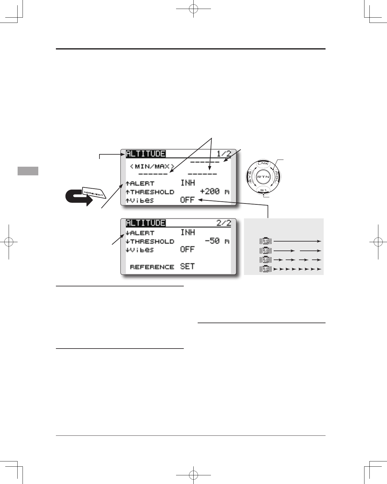
TELEMETRY : ALTITUDE Displaying data from the altitude
ALTITUDE is a screen which displays / sets up the
altitude information from an optional altitude sensor or
GPS sensor. The altitude of the model which is ying can
be known. If it becomes higher (low) than preset altitude,
you can be told by alarm. To show warning by vibration
can also be chosen. Data when a power supply is turned
on shall be 0 m, and it displays the altitude which
changed from there. Even if the altitude of an aireld is
high, that shall be 0 m and the altitude difference from an
airfield is displayed. This sensor calculates the altitude
from atmospheric pressure. Atmospheric pressure will
get lower as you go up in altitude, using this the sensor
will estimate the altitude. Please understand that an exact
advanced display cannot be performed if atmospheric
pressure changes in a weather situation.
*It cannot be used in FASST mode and S-FHSS mode.
*Only receiver voltage and EXT voltage can be used in
FASSTest12CH mode.
*The FASSTest14CH mode can use all the telemetry functions.
● Select [ALTITUDE] in the TELEMETRY screen and access the
setup screen shown below by touching the RTN button.
Scrolling
● Moving cursor
● Selecting mode
● Adjusting value
● To next page
● Altitude
● The maximum and the minimum when
powering ON are shown.
● ↓ An downward arrow
indicates the alarm
will sound when the
altitude reaches
below your set value.
● ↑ An upward arrow
indicates the alarm will
sound when the altitude
reaches above your set
value.
First, the set of a reference is required.
1. The model and transmitter to which the
altitude sensor was connected are turned on.
2. Move the cursor to the [SET] of "REFERENCE"
item and touch the RTN button to switch to
the data input mode.
3. Touch the RTN button. (To terminate the input and
return to the original state, touch the S1 button.)
*Atmospheric pressure is changed according to the weather also
at the same aireld. You should preset before a ight.
Alert set : High side
1. Move the cursor to the ↑ALERT item and
touch the RTN button to switch to the data
input mode.
2. Select the ACT mode by scrolling the touch
sensor.
3. Touch the RTN button. (To terminate the input
and return to the original state, touch the S1
button.)
4. Move the cursor to the ↑THRESHOLD [+200m]
item and touch the RTN button to switch to
the data input mode.
5. Ajust the rate by scrolling the touch sensor.
Initial value: +200m
Adjustment range: -499m~+5,000m
(↑THRESHOLD > ↓THRESHOLD)
*When the RTN button is touched for one second, the rate is
reset to the initial value.
6. Touch the RTN button. (To terminate the input
and return to the original state, touch the S1
button.)
Alert set : Low side
1. Scroll to the second page by pushing S1. Move
the cursor to the ↓ALERT item and touch the
RTN button to switch to the data input mode.
2. Select the ACT mode by scrolling the touch
sensor.
3. Touch the RTN button. (To terminate the input
and return to the original state, touch the S1
button.)
4. Move the cursor to the ↓THRESHOLD [-50m]
item and touch the RTN button to switch to
the data input mode.
5. Ajust the rate by scrolling the touch sensor.
Initial value: -50m
Adjustment range: -500m~+4,999m
(↑THRESHOLD > ↓THRESHOLD)
*When the RTN button is touched for one second, the rate is
reset to the initial value.
6. Touch the RTN button. (To terminate the input and
return to the original state, touch the S1 button.)
TYPE 1
TYPE 2
TYPE 3
TYPE 4
"Vibes" type
If the following types are selected, the
transmitter will vibrate during the warning.
*An altitude sensor or GPS sensor must be installed in the aircraft.
●Press the S1 button to advance to the next page.
97
<Functions of Linkage Menu>
● Select the function name
and return to the Linkage
menu by touching the
RTN button. Or the
HOME/EXIT button is
pushed.
<SensorTouch™>
RETURN
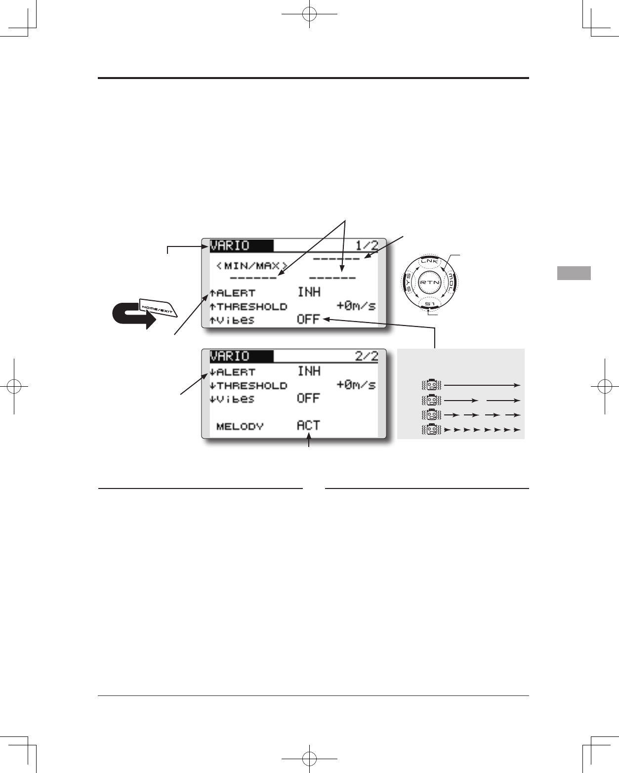
TELEMETRY : VARIO Displaying data from the variometer
VARIO is a screen which displays / sets up the
variometer information from an optional altitude
sensor or GPS sensor.
The variometer of the model which is ying can
be known.
If it becomes higher or lower than the setting an
alarm and/or vibration will alert you.
To ensure that the pilot is aware as to the model's
status, the T14SG incorporates a different melody
for ascent and descent. Additionally, depending
upon the rate of climb or descent, the tones vary to
indicate whether or not the airplane is climbing or
descending at a rapid rate.
*It cannot be used in FASST mode and S-FHSS mode.
*Only receiver voltage and EXT voltage can be used in
FASSTest12CH mode.
*The FASSTest14CH mode can use all the telemetry functions.
● Select [VARIO] in the TELEMETRY screen and access
the setup screen shown below by touching the RTN
button.
Scrolling
● Moving cursor
● Selecting mode
● Adjusting value
● To next page
● Variometer
● The maximum and the minimum when
powering ON are shown.
● If this is set to ACT, a melody will be activated during the
rise or dive, depending on your set values.
● ↓ An downward arrow
indicates the alarm will
sound when the altitude
reaches below your set
value.
● ↑ An upward arrow
indicates the alarm will
sound when the altitude
reaches above your set
value.
Alert set : Rise side
1. Move the cursor to the ↑ALERT item and
touch the RTN button to switch to the data
input mode.
2. Select the ACT mode by scrolling the touch
sensor.
3. Touch the RTN button. (To terminate the input
and return to the original state, touch the S1
button.)
4. Move the cursor to the ↑THRESHOLD [+0m/s]
item and touch the RTN button to switch to
the data input mode.
5. Ajust the rate by scrolling the touch sensor.
Initial value: +0m/s
Adjustment range: -49m/s~+50m/s
(↑THRESHOLD > ↓THRESHOLD)
*When the RTN button is touched for one second, the rate is
reset to the initial value.
6. Touch the RTN button. (To terminate the input
and return to the original state, touch the S1
button.)
Alert set : Dive side
1. Scroll to the second page by pushing S1.
Move the cursor to the ↓ALERT item and
touch the RTN button to switch to the data
input mode.
2. Select the ACT mode by scrolling the touch
sensor.
3. Touch the RTN button. (To terminate the input
and return to the original state, touch the S1
button.)
4. Move the cursor to the ↓THRESHOLD [+0m/s]
item and touch the RTN button to switch to
the data input mode.
5. Ajust the rate by scrolling the touch sensor.
Initial value: +0m/s
Adjustment range: -50m/s~+49m
(↑THRESHOLD > ↓THRESHOLD)
*When the RTN button is touched for one second, the rate is
reset to the initial value.
6. Touch the RTN button. (To terminate the input and
return to the original state, touch the S1 button.)
TYPE 1
TYPE 2
TYPE 3
TYPE 4
"Vibes" type
*An altitude sensor or GPS sensor must be installed in the aircraft.
If the following types are selected, the
transmitter will vibrate during the warning.
●Press the S1 button to advance to the next page.
98 <Functions of Linkage Menu>
● Select the function name
and return to the Linkage
menu by touching the
RTN button. Or the
HOME/EXIT button is
pushed.
<SensorTouch™>
RETURN
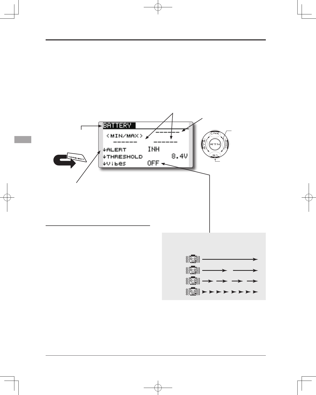
TELEMETRY : BATTERY Displaying data from the battery voltage
In this screen, the battery voltage is displayed.
In order to use this function, it is necessary to
connect External voltage connector of R7008SB ⇔
SBS-01V ⇔ Battery
SBS-01V measures two batteries. The drive
battery connected to two lines is displayed on EXT-
VOLT. The battery for receivers connected to 3P
lines is displayed here.
*It cannot be used in FASST mode and S-FHSS mode.
*Only receiver voltage and EXT voltage can be used in
FASSTest12CH mode.
*The FASSTest14CH mode can use all the telemetry functions.
● Select [BATTERY] in the TELEMETRY screen and
access the setup screen shown below by touching
the RTN button.
Scrolling
● Moving cursor
● Selecting mode
● Adjusting value
● To next page
● battery voltage
● The maximum and the minimum when
powering ON are shown.
● ↓The arrow will indicate that
an alarm will sound when
the voltage drops to below
the setting.
Alert set
1. Move the cursor to the ↓ALERT [INH] item and
touch the RTN button to switch to the data
input mode.
2. Select the ACT mode by scrolling the touch
sensor.
3. Touch the RTN button. (To terminate the input
and return to the original state, touch the S1
button.)
4. Move the cursor to the ↓THRESHOLD [4.0V]
item and touch the RTN button to switch to
the data input mode.
5. Ajust the rate by scrolling the touch sensor.
Initial value: 4.0V
Adjustment range: 0.0V~8.4V
*When the RTN button is touched for one second, the rate is
reset to the initial value.
6. Touch the RTN button. (To terminate the input
and return to the original state, touch the S1
button.)
TYPE 1
TYPE 2
TYPE 3
TYPE 4
"Vibes" type
If the following types are selected, the transmitter will
vibrate during the warning.
*SBS-01V must be installed in the aircraft.
99
<Functions of Linkage Menu>
● Select the function name
and return to the Linkage
menu by touching the
RTN button. Or the
HOME/EXIT button is
pushed.
<SensorTouch™>
RETURN
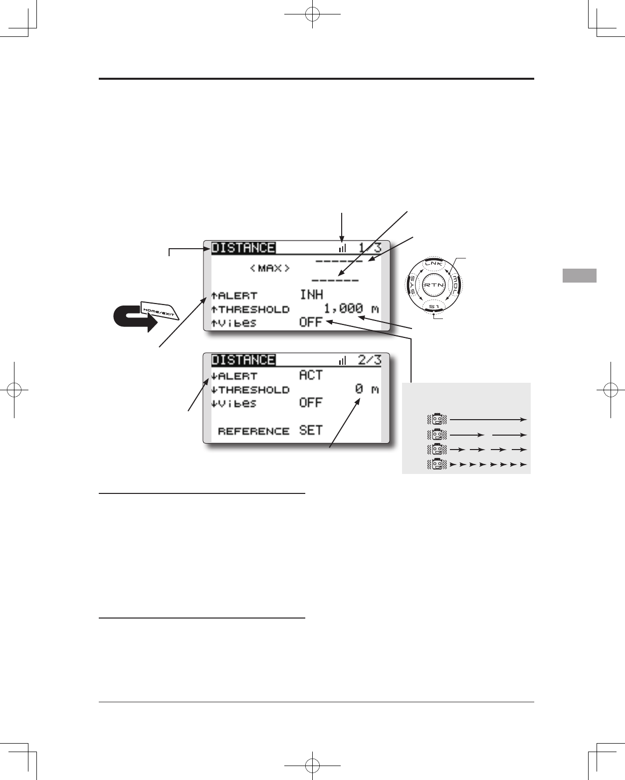
TELEMETRY : DISTANCE Displaying data from the distance
Distance is a screen that displays and sets the
altitude data from an SBS-01G (GPS Sensor) sold
separately. The distance to the airborne aircraft
can be read by the transmitter. When the aircraft
ies outside (inside) the set distance the operator is
alerted by an alarm and vibration.
*The GPS sensor sold separately is necessary. Mount and
connect the sensor in accordance with the sensor instruction
manual.
*It cannot be used in FASST mode and S-FHSS mode.
*Only receiver voltage and EXT voltage can be used in
FASSTest12CH mode.
*The FASSTest14CH mode can use all the telemetry functions.
● Select [DISTANCE] in the TELEMETRY screen and access
the setup screen shown below by touching the RTN
button.
Scrolling
● Moving cursor
● Selecting mode
● Adjusting value
● To next page
●Current distance
●Distance alarm setting range
1m ~ 5,000m
*Alarm when the aircraft moves far
away.
(↑THRESHOLD > ↓THRESHOLD)
●Distance alarm setting range 0m ~ 4,999m
(↑THRESHOLD > ↓THRESHOLD)
● Maximum distance after
transmitter was turned on.
● The ↓arrow shows
that an alarm is
generated when
the distance drops
below the set value.
● The ↑arrow shows
that an alarm is
generated when
the set value is
exceeded.
First, the set of a reference is required.
1. The model and transmitter to which the GPS
sensor was connected are turned on.
2. It waits until the GPS receiving accuracy
displayed on a screen becomes three.
3. Move the cursor to the [SET] of "REFERENCE"
item and touch the RTN button to switch to
the data input mode.
4. Touch the RTN button. (To terminate the input and
return to the original state, touch the S1 button.)
*Now, the position of the present model was set to 0 m.
Alert setting when aircraft goes too far
1. Move the cursor to the ↑ALERT item and
touch the RTN button to switch to the data
input mode.
2. Select the ACT mode by scrolling the touch
sensor.
3. Touch the RTN button. (To terminate the input
and return to the original state, touch the S1
button.)
4. Move the cursor to the ↓THRESHOLD [1,000m]
item and touch the RTN button to switch to
the data input mode.
5. Ajust the rate by scrolling the touch sensor.
*When the RTN button is touched for one second, the rate is
reset to the initial value.
6. Touch the RTN button. (To terminate the input
and return to the original state, touch the S1
button.)
TYPE 1
TYPE 2
TYPE 3
TYPE 4
"Vibes" type
*A GPS sensor must be installed in the aircraft.
If the following types are selected, the
transmitter will vibrate during the warning.
●Press the S1 button to advance to the next page.
G
G
●It is the receiving accuracy from a GPS
Satellite. Please wait until it becomes 3
displays, and push [REFERENCE].
100 <Functions of Linkage Menu>
● Select the function name
and return to the Linkage
menu by touching the
RTN button. Or the
HOME/EXIT button is
pushed.
<SensorTouch™>
RETURN
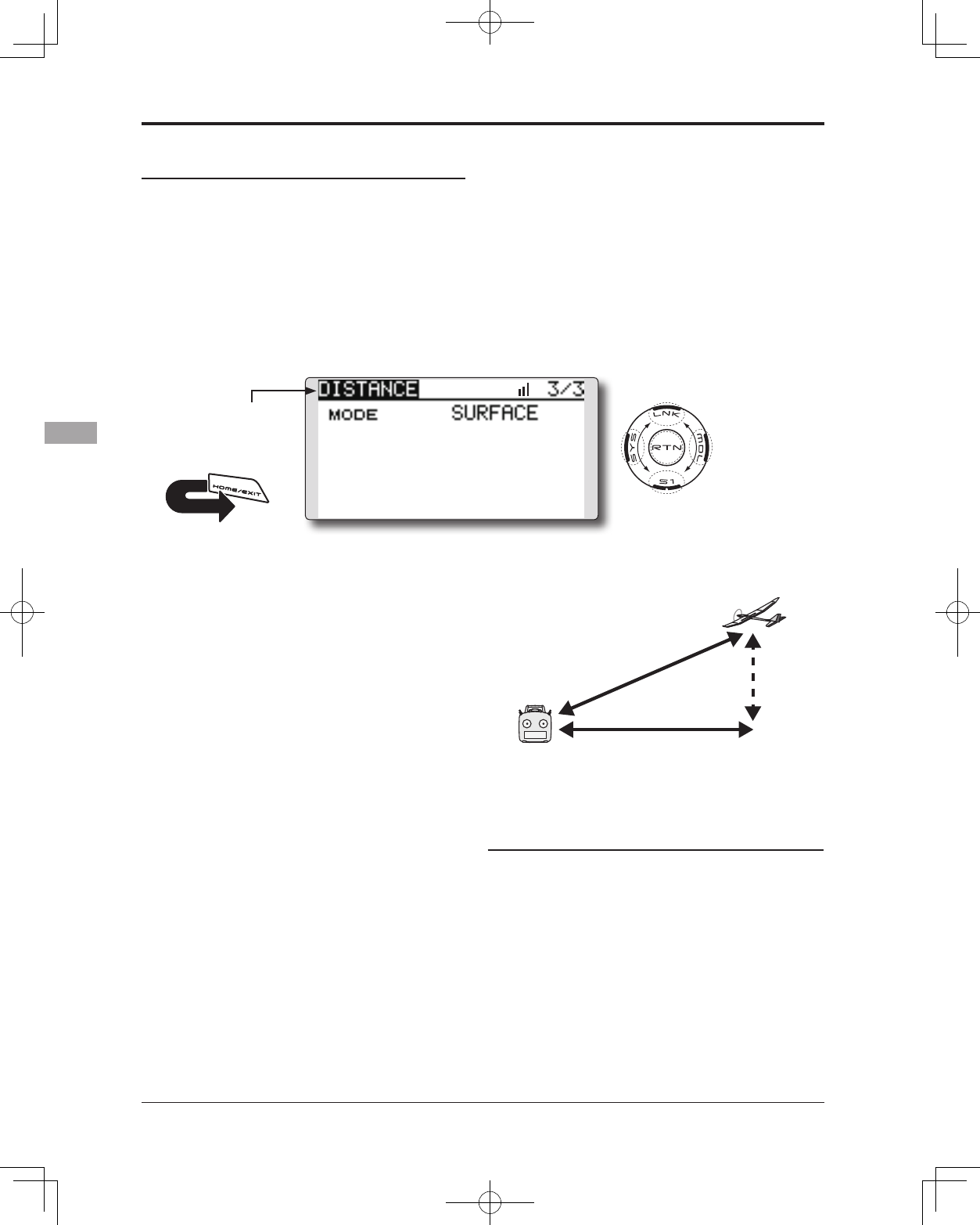
G
Surface
Altitude
Slant
●Altitude calculated as
either straight line
distance (slant) or surface
distance on a map can
also be selected
(3/3)
Alert setting when the aircraft approaches
1. Access the second page by pushing S1.
Move the cursor to the ↓ALERT item and
touch the RTN button to switch to the data
input mode.
2. Select the ACT mode by scrolling the touch
sensor.
3. Touch the RTN button. (To terminate the input
and return to the original state, touch the S1
button.)
4. Move the cursor to the ↓THRESHOLD [0m]item
and touch the RTN button to switch to the
data input mode.
5. Ajust the rate by scrolling the touch sensor.
*When the RTN button is touched for one second, the rate is
reset to the initial value.
6. Touch the RTN button. (To terminate the input
and return to the original state, touch the S1
button.)Slant and surface distance
● Select [DISTANCE] in the TELEMETRY screen by touching
the RTN button. And S1 button is touched twice.
Two displays methods, straight line distance and
surface distance, can be selected as shown above.
1. Select page 3 by touching the S1 button twice
from the “DISTANCE” screen.
2. Select <SLANT> <SURFACE> next to “MODE”,
scroll to the desired method and touch the
RTN button.
101
<Functions of Linkage Menu>
● Select the function name
and return to the Linkage
menu by touching the
RTN button. Or the
HOME/EXIT button is
pushed.
<SensorTouch™>
RETURN
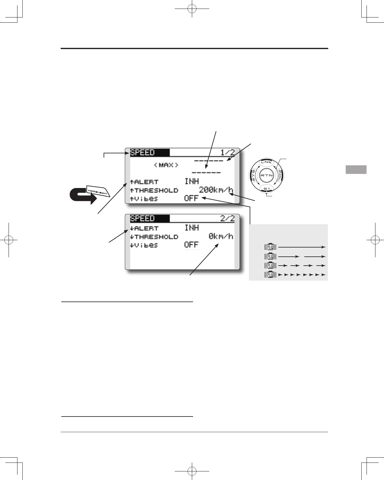
TELEMETRY : SPEED Displaying data from the speed
The speed screen displays and sets the speed data
from an SBS-01G (GPS sensor) sold separately.
The speed of the aircraft during flight can be
displayed.
After flight, the maximum speed during flight
can be viewed. Because this speed is based on
position data from a GPS satellite, the ground speed
is displayed instead of air speed. Consequently,
with a head wind, the displayed speed decreases
and with a tail wind, the displayed speed increases.
*It cannot be used in FASST mode and S-FHSS mode.
*Only receiver voltage and EXT voltage can be used in
FASSTest12CH mode.
*The FASSTest14CH mode can use all the telemetry functions.
● Select [SPEED] in the TELEMETRY screen and access the
setup screen shown below by touching the RTN button.
Scrolling
● Moving cursor
● Selecting mode
● Adjusting value
● To next page
●Displays the current speed
● Displays the maximum speed after
the transmitter is turned on.
●Speed alarm setting range
1~500km/h
(↑THRESHOLD > ↓THRESHOLD)
*Alarm when the speed has increased.
●Speed alarm setting range 0 ~499km/h
(↑THRESHOLD > ↓THRESHOLD)
*Alarm when the speed has decreased.
● The ↓ arrow shows
that an alarm is
generated when
the speed drops
below the set value.
● The ↑ arrow shows
that an alarm is
generated when
the speed exceeds
the set value.
Alert setting when speed increases
1. Set “↑ALERT” on the <SPEED> screen to ACT.
Move the cursor to INH and touch the RTN
button.
2. Select the ACT mode by scrolling the touch
sensor.
3. Touch the RTN button. (To terminate the input
and return to the original state, touch the S1
button.)
4. The speed at which an alarm is generated can
be set by selecting the speed display next to “↑
THRESHOLD” and touching the RTN button. This
generates an alarm when the speed increases.
5. Ajust the rate by scrolling the touch sensor.
*When the RTN button is touched for one second, the rate is reset
to the initial value.
6. Touch the RTN button. (To terminate the input
and return to the original state, touch the S1
button.)
Alert setting when speed decreases
1. Select page 2 by pressing S1 from the <SPEED>
screen and set “ ↓ ALERT” to ACT.
2. Select the ACT mode by scrolling the touch
sensor.
3. Touch the RTN button. (To terminate the input
and return to the original state, touch the S1
button.)
4.The speed at which an alarm is generated
can be set by selecting the numerical display
next to “ ↓ THRESHOLD” and touching the RTN
button. This sounds an alarm when the speed
decreases.
5. Ajust the rate by scrolling the touch sensor.
*When the RTN button is touched for one second, the rate is reset
to the initial value.
6. Touch the RTN button. (To terminate the input
and return to the original state, touch the S1
button.)
*Speed alarm precaution
Since the GPS speed sensor displays the ground speed, it cannot
be used as a stall alarm. For example, an aircraft that stalls
at 50km/h will stall if the tailwind is 5km/h or greater even
through 55km/h is displayed by ground speed. In addition,
with an aircraft that will disintegrate in midight at 400km/h at
an over-speed alarm, when the headwind reaches 30km/h the
airplane will disintegrate in midair due to over speeding even at
a ground speed of 370km/h.
*A GPS sensor must be installed in the aircraft.
TYPE 1
TYPE 2
TYPE 3
TYPE 4
"Vibes" type
If the following types are selected, the
transmitter will vibrate during the warning.
●Press the S1 button to advance to the next page.
102 <Functions of Linkage Menu>
● Select the function name
and return to the Linkage
menu by touching the
RTN button. Or the
HOME/EXIT button is
pushed.
<SensorTouch™>
RETURN
SENSOR Various telemetry sensors setting
This screen registers the telemetry sensors used
with the transmitter. When only one of a certain
type of sensor is used, this setting is unnecessary
and the sensor can be used by simply connecting it
to the S.BUS2 port of the transmitter.
When using 2 or more of the same kind of
sensor, they must be registered here.
● Select [SENSOR] in the Linkage menu and
access the setup screen shown below by
touching the RTN button.
● Sensor ID: When multiple sensors of the
same type are not used, ID is unnecessary.
● As shown in the table below, an altimeter requires 3 contiguous slots
and a GPS sensor requires 8 contiguous slots. In addition, since the GPS
(SBS-01G) start slots are 8, 16, and 24, slots 6 and 7 are inhibited.
<Assignable slot >*Altimeter, GPS, and other sensors that display a large amount of data require multiple slots.
*Depending on the type of sensor, the slot numbers that can be allocated may be limited.
[What is a slot?]
Servos are classified by CH, but sensors are
classified in units called “slot”. There are slots
from No. 1 to No. 31.
Altitude sensors, GPS sensors and other data
sensor units may use multiple slots.
Using a sensor which uses two or more slots,
the required number of slots is automatically
assigned by setting up a start slot.
When 2 or more of the same kind of sensor are
used, the sensors themselves must allocate unused
slots and memorize that slot.
*3 slots of altitude sensor are used.
*8 slots of GPS sensor are used.
Sensor Therequired
numberofslots Thenumberwhichcanbeusedasastartslot Sellingarea
TEMP(SBS-01T) 1slot 1 ~31
Global
RPM(SBS01RM,SBS-
01RO) 1slot 1 ~31
Voltage(SBS-01V) 2slots 1,2,3,4,5,6,8,9,10,11,12,13,14,16,17,18,19,20,21,
22,24,25,26,27,28,29,30
Altitude(SBS-01A) 3slots 1,2,3,4,5,8,9,10,11,12,13,16,17,18,19,20,21,24,2
5,26,27,28,29
GPS(SBS-01G) 8slots 8,16,24
TEMP125-F1713 1slot 1 ~31
Europe
VARIO-F1712 2slots 1,2,3,4,5,6,8,9,10,11,12,13,14,16,17,18,19,20,21,
22,24,25,26,27,28,29,30
VARIO-F1672 2slots 1,2,3,4,5,6,8,9,10,11,12,13,14,16,17,18,19,20,21,
22,24,25,26,27,28,29,30
GPS-F1675 8slots 8,16,24
103
<Functions of Linkage Menu>
● Select the function name
and return to the Linkage
menu by touching the
RTN button. Or the
HOME/EXIT button is
pushed.
<SensorTouch™>
RETURN
● Call page 7 by touching the S1 button 6 times from
the [SENSOR] menu.
SENSOR : RELOAD
SENSOR : REGISTER
This page is set when using multiple telemetry sensors of the same type.
This page is set when using multiple telemetry sensors of the same type.
When using multiple sensors of the same type
the sensors must be registered in the transmitter.
Connect all the sensors to be used to the T14SG as
shown in the gure at the right and register them by
the following procedure. The ID of each sensor is
registered in the transmitter.
This function registers an additional sensor.
Connect the sensor as shown in the figure at the
right and register it by the following procedure.
The sensor ID is registered in the transmitter.
All the sensors to be used are connected.
SENSOR
SENSOR
3-way hub
or Y-harnesses
Receivers
Battery
T14SG
SENSOR
SENSOR
SENSOR
3-way hub
or Y-harnesses
Receivers
Battery
T14SG
SENSOR
Reading all the sensors to be used
1. Connect all the sensors and receiver
batteries to be used to the T14SG through a
hub as shown in the gure above.
2. Move the cursor to “RELORD” on page 7 of
the [SENSOR] screen.
3. Touch the RTN button.
All the sensors are registered and can be
used.
Additional sensor registration
1. Connect the sensor and receiver battery
to be used to the T14SG through a hub as
shown in the gure at the right.
2. Move the cursor to “REGISTER” on page 7 of
the <Sensor> screen.
3. Touch the RTN button.
The sensor is registered and can be used.
*When the number of slots needed in registration is
insufcient, an error is displayed and registration cannot be
performed. Disable unused slots or perform the following
relocate.
104 <Functions of Linkage Menu>
● Select the function name
and return to the Linkage
menu by touching the
RTN button. Or the
HOME/EXIT button is
pushed.
<SensorTouch™>
RETURN
This function secures contiguous unused slots
by rearranging the registration state when sensor
registration and deregistration are performed
repeatedly and the unused slots are fragmented.
Relocate of sensors to be used
1. Connect all the sensors and receiver
batteries to be used to the T14SG through a
hub as shown in the gure above.
2. Move the cursor to “RELOCATE” on page 7 of
the [SENSOR] screen.
3. Touch the RTN button.
This procedure changes the slot No. of one
registered sensor.
Sensor slot change
1. Connect the sensor and receiver battery to
be changed to the T14SG through a hub as
shown in the gure above.
2. Move the cursor to “SET SLOT” on page 7 of
the <Sensor> screen.
3. Touch the RTN button. A sensor details screen
appears.
4. Move the cursor to “LOAD” and touch the
RTN button.
5. The current start slot is displayed. Move the
cursor to the number of the start slot and
change it to the desired value.(Cannot be
set to a slot that cannot be allocated like the
table of all pages.)
6. Move the cursor to “WRITE” and touch the
RTN button.
All the sensors to be used are connected.
SENSOR
SENSOR
3-way hub
or Y-harnesses
Receivers
Battery
T14SG
SENSOR
SENSOR
SENSOR
SENSOR : RELOCATE
SENSOR : SET SLOT
3-way hub
or Y-harnesses
Receivers
Battery
T14SG
SENSOR
This page is set when using multiple telemetry sensors of the same type.
This page is set when using multiple telemetry sensors of the same type.
● Call page 7 by touching the S1 button 6 times from
the [SENSOR] menu.
105
<Functions of Linkage Menu>
● Select the function name
and return to the Linkage
menu by touching the
RTN button. Or the
HOME/EXIT button is
pushed.
<SensorTouch™>
RETURN
DATA RESET Model memory setting data reset.
This function is designed to allow you to reset
trim settings or all of the settings saved in the active
model memory. You may individually choose to
reset the following data;
T1~T4:
Reset the digital trim setting.
*The trim step amount and trim rate are not reset.
Data resetting method
1. Move the cursor to the item you want to
reset and touch the RTN button.
*A conrmation message appears.
2. Execute reset by touching the RTN button for
one second. (Touch the S1 button to cease
resetting.)
[T1-T4]: Resets only the T1-T4
[ALL MODEL SETTING]: Resets all the functions
in the Linkage menu and Model menu
except the frequency, model select, and
model type functions.
[TELEMETRY]: Resets only the teremetry
functions.
All model setting:
Resets all Linkage and Model Menu functions
except for Frequency, Model Select, Low battery
voltage, and Model Type.
*If the Model Type selected is Glider, the motor function
channel is automatically reversed in the Reverse menu; all
other channels remain normal.
TELEMETRY:
Reset the telemetry setting.
● Select [DATA RESET] in the Linkage menu and
access the setup screen shown below by touching
the RTN button.
Scrolling
● Moving cursor
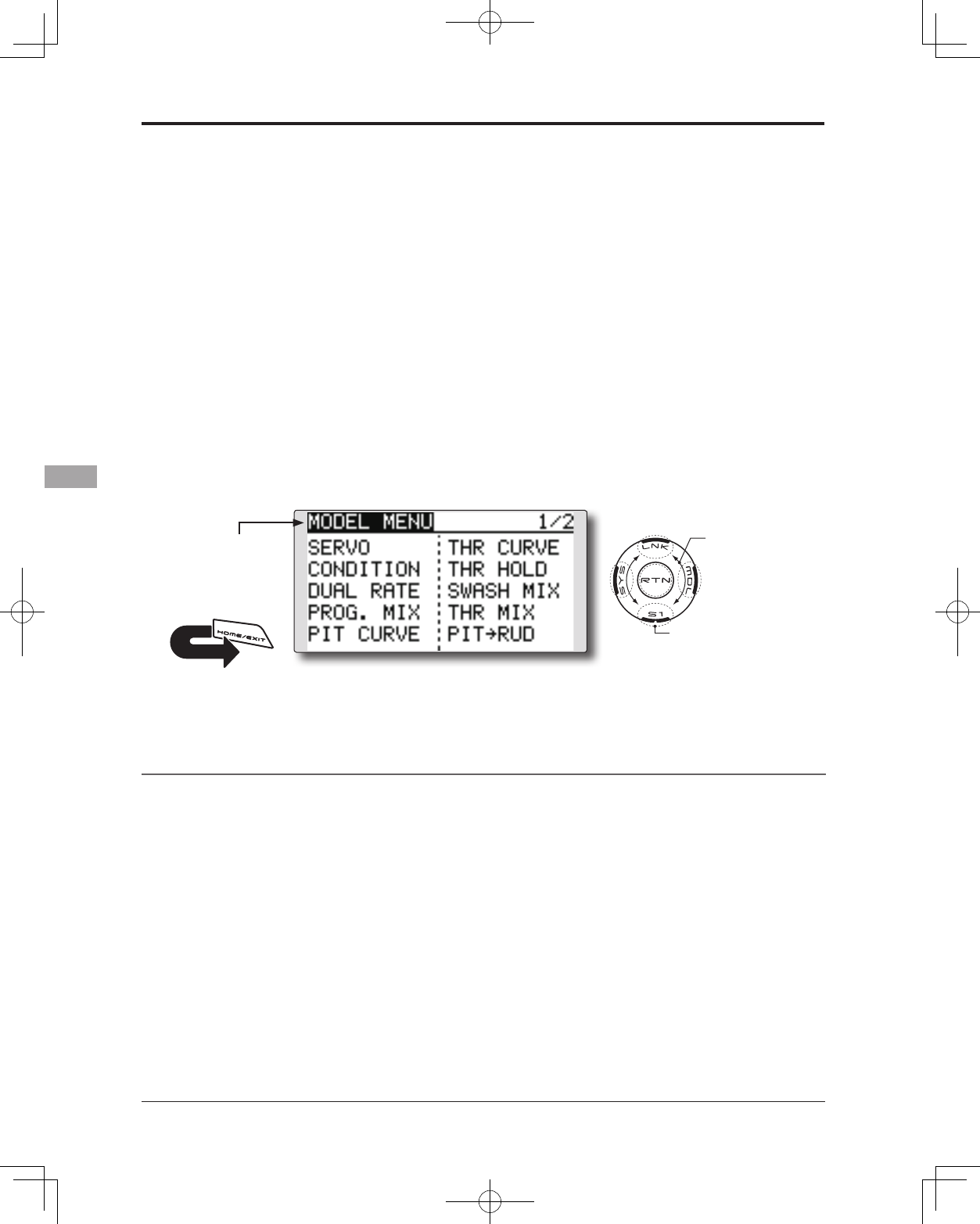
106 <Model Menu (Common Functions)>
MODEL MENU (COMMON FUNCTIONS)
This section describes the D/R, program mixing,
and other functions common to all model types.
Before setting the model data, use the Model
Type function of the Linkage menu to select the
model type matched to the aircraft. If a different
model type is selected afterwards, the D/R, program
mixing, and other parameters are reset.
If either a helicopter or glider have been selected
as the model type, then the specic functions in the
Model menu can be set for each ight condition. If
you want to switch the settings for each condition
by switch, stick position, etc., use the Condition
Select function to add ight conditions. (Up to ve
conditions can be used)
Note: The T14SG is designed so that the airplane
and glider (including EP glider) model types
are compatible with aircraft of similar type
wings.
This section outlines the relationship between
the functions common to airplanes and
gliders, except some dedicated functions,
and model type.
The setting menus will depend on the number
of servos and other differences according to
the wing type used. The setup screens in the
instruction manual are typical examples.
*The Model menu screen depends on the
model type.
Model Menu functions (Common) list
●SERVO
Servo test and servo position display (For a
description of its functions, see the Linkage Menu
section.)
●CONDITION (applicable to helicopter and
glider selections)
Flight conditions addition, deletion, copy,
condition renaming, and condition delay can be set.
●DUAL RATE
The D/R curve of a T14SG transmitter may be
activated from a switch, stick, position, etc. For
information on how to do so, please refer to the
Switch Setting Method located at the back of this
manual.
●PROG. MIX
The T14SG transmitter allows up to five
completely customizable program mixes.
● Access the model menu shown below by
touching the MDL button twice at the home
screen, etc.
● Select the function
name and return to
the Model menu by
touching the RTN
button. Or a HOME/
EXIT button is pushed.
<SensorTouch™>
● Select the function you want to set and
access the setup screen by touching the RTN
button.
Scrolling
● Moving cursor
● To next page
RETURN
107
<Model Menu (Common Functions)>
● Select the function name
and return to the Model
menu by touching the
RTN button. Or the
HOME/EXIT button is
pushed.
<SensorTouch™>
RETURN
CONDITION Flight condition's switch assignment, copy, priority change and
condition delay can be set. [except airplane type]
This function, in the Model menu, can be used
to switch the settings of up to 5 ight conditions.
Please note this is not applicable to airplane type
selections.
Note: To prevent accidental activation of any
unused ight conditions during ight, set the
switch setting of those unused conditions to
null [--].
● A Condition Delay function can be set.
Unnecessary fuselage motion which may be
generated when there are sudden changes
in the servo positions and when there are
variations in the operating time between
channels during condition switching. The
delay can be set for each channel to ensure
maximum performance from your aircraft.
When setting the delay function for a specic
ight condition, the related function changes
after a delay corresponding to the set
amount.
● If multiple conditions were set, their
operational priority may be customized as
desired.
(Currently selected condition name)
● Select [CONDITION] at the Model menu and
access the setup screen shown below by touching
the RTN button.
Select the copy destination condition by
scrolling the touch sensor. Then, touch the
RTN button.
*The current condition can not be selected for the copy
destination condition.
3. Move the cursor to the [COPY] item and
touch the RTN button. A confirmation
message appears.
*The display blinks.
4. Touch the RTN button for one second and
the copying is completed. (Touch the S1
button to stop copying.)
Priority change
1. Move the cursor to the priority up-arrow or
down-arrow you want to change and touch
the RTN button.
The priority of the corresponding condition is
changed. (The last condition becomes the
highest priority.)
*The Normal condition cannot be changed or moved, its
priority is always the lowest.
Condition switch selection/deletion
1. Move the cursor to the switch item of the
condition you want to select/delete and
access the switch setup screen by touching
the RTN button and select the switch and ON
direction.
*For a detailed description of the setting method, see [Switch
Setting Method] at the back of this manual.
Condition copy
(Setup screen page 3)
1. Move the cursor to the [SOURCE] item and
touch the RTN button to switch to the data
input mode.
Select the copy source condition by scrolling
the touch sensor. Then, touch the RTN button.
2. Move the cursor to the [DESTIN.] item and
touch the RTN button.
Scrolling
● Moving cursor
● Selecting mode
● Adjusting value
● To next page
(Condition name) (Condition switch)
108 <Model Menu (Common Functions)>
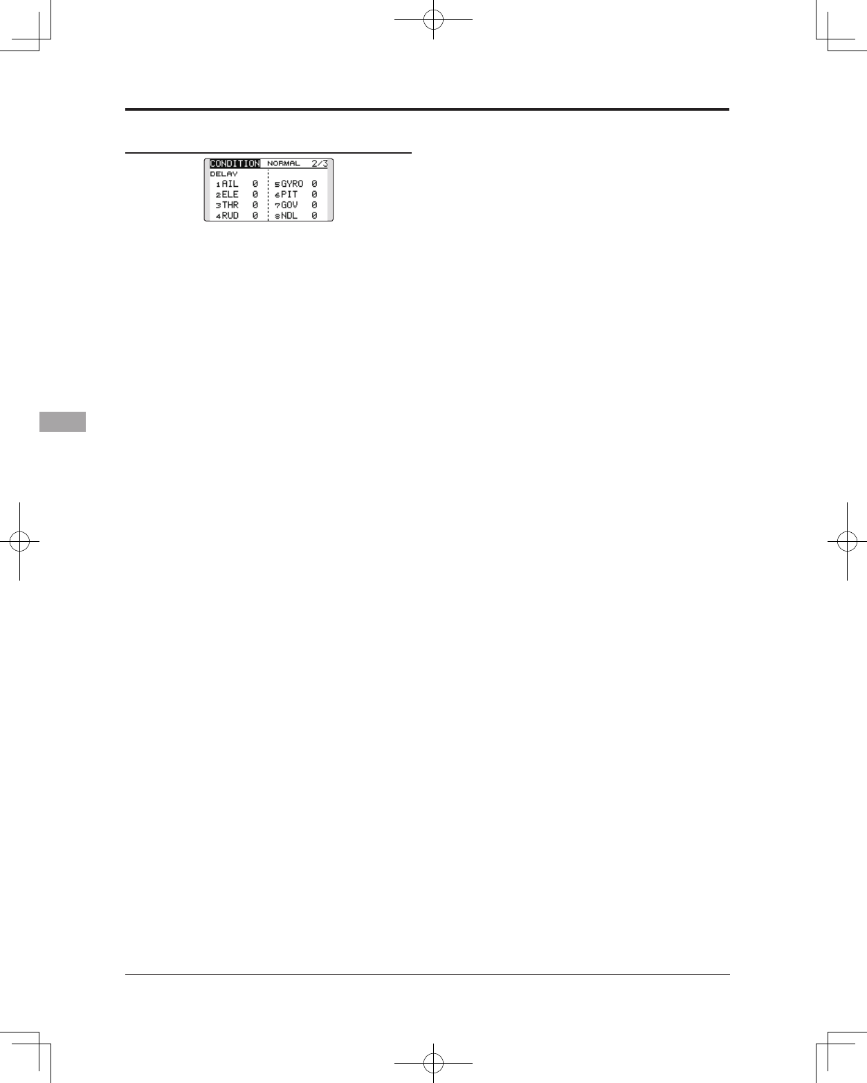
Condition delay setting
(Setup screen page 2)
1. Select the condition which you want to set.
2. Move the cursor to the "DELAY" icon of the
channel you want to set and touch the RTN
button to switch to the data input mode.
Adjust the delay amount by scrolling the
touch sensor.
Initial value: 0
Adjustment range: 0~27 (maximum delay)
3. Touch the RTN button to end adjustment and
return to the cursor mode.
109
<Model Menu (Common Functions)>
● Select the function name
and return to the Model
menu by touching the
RTN button. Or the
HOME/EXIT button is
pushed.
<SensorTouch™>
RETURN
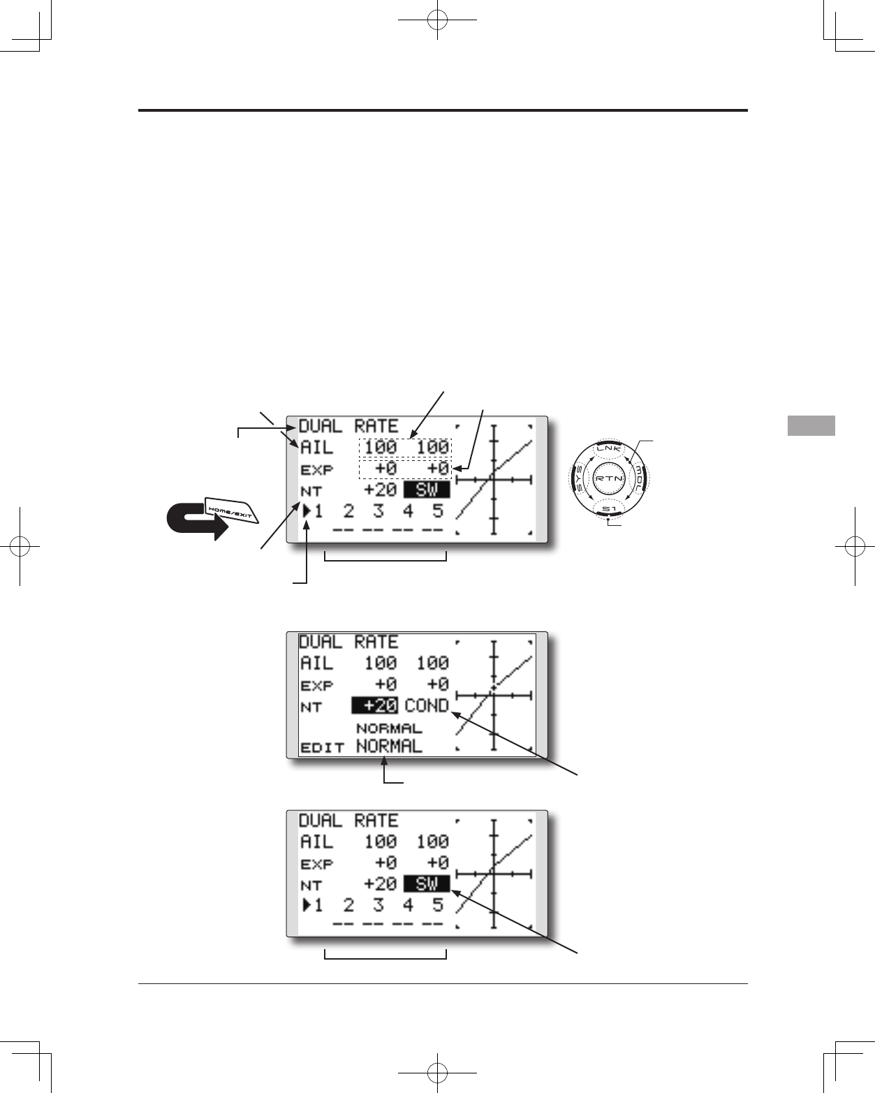
DUAL RATE The angle and curve of each stick function can be set. [All model types]
Dual rate function is used to adjust the amount
of throw and the operational curve of the stick
functions (aileron, elevator and rudder) for each
ight condition or up to 5 rates for each function.
For airplane type, it is also possible to adjust the
operational curve of the throttle function.
This is normally used after the End Point
programming has been completed to define the
maximum throw. When mixing is applied from one
channel to another channel, both channels can be
adjusted at the same time by adjusting the operation
rate through the dual rate function.
Neutral position of the dual rate curve can be
set.
Dual rate curve of FLAP, FLAP3, BUTTERFLY,
and CAMBER function can be set. (Airplane/
Glider)
*FLAP3 and BUTTERFLY are glider only functions.
*EXP rate setting is not allowed in the FLAP,
FLAP3,BUTTERFLY, and CAMBER functions.
*Individual switch setting is not allowed in the FLAP,FLAP3,
and BUTTERFLY, CAMBER functions. (Condition
switching only)
● Select [DUAL RATE] at the Model menu and access
the setup screen shown below by touching the
RTN button.
(Currently selected circuit #)
●Neutral position
Scrolling
● Moving cursor
● Selecting mode
● Adjusting value
● To next page
●Left/right (up/down) rate
●Operation curve (left/right, up/down)
●Switch selection
[Airplane]
[Helicopter/glider]
●Condition Mode
selection
●Switch mode
selection
●Condition selection
●Switch selection
*Up to ve rates for each function
●Function selection

110 <Model Menu (Common Functions)>
Dual rate setting procedure
1. Function selection
Move the cursor to the function selection
item and touch the RTN button to switch to
the data input mode.
Select the function you want to adjust by
scrolling the touch sensor.
Touch the RTN button to the cursor mode.
2. Switch selection
Move the cursor to the circuit # item and
access the switch setup screen by touching
the RTN button. Select the switch activation
method and the activation position (if
applicable).
*For a detailed description of the setting method, see [Switch
Setting Method] at the back of this manual.
3. Left/right (up/down) rate adjustment
*Perform the settings below after changing to the circuit # or
condition you want to adjust.
Move the cursor to the rate item you want to
adjust and touch the RTN button to switch to
the data input mode.
Adjust the rate by scrolling the touch sensor.
Initial value: 100%
Adjustment range: 0%~140%
*When the RTN button is touched for one second, the servo
operation position is reset to the initial value.)
Touch the RTN button to end the adjustment
and return to the cursor mode.
Repeat this procedure for additional rate
and other functions as desired.
4. Operation curve (EXP curve) adjustment
*Perform the settings below after changing to the circuit # or
condition you want to adjust.
Move the cursor to the EXP item you want to
adjust and touch the RTN button to switch to
the data input mode.
Adjust the rate by scrolling the touch sensor.
Initial value: 0%
Adjustment range: -100%~+100%
*When the RTN button is touched for one second, the servo
operation position is reset to the initial value.)
*Using the EXP curve is effective to smoothe or soften the
control inputs around center to avoid over-controlling the
model. This is often used for the ailerons, elevator and
rudder and may be used with the throttle in the case of an
airplane selection to smoothe the engine controls as well.
Touch the RTN button to end adjustment and
return to the cursor mode.
Repeat this procedure for all other rates and
functions as desired.
5. Neutral position adjustment
*Perform the settings below after changing to the circuit # or
condition you want to adjust.
Move the cursor to the [NT] item and touch
the RTN button to switch to the data input
mode.
Adjust the rate by scrolling the touch sensor.
Initial value: 0%
Adjustment range: -100%~+100%
*When the RTN button is touched for one second, the neutral
position is reset to the initial value.)
Touch the RTN button to the cursor mode.
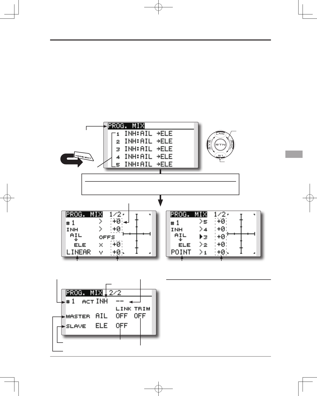
111
<Model Menu (Common Functions)>
● Select the function name
and return to the Model
menu by touching the
RTN button. Or the
HOME/EXIT button is
pushed.
<SensorTouch™>
RETURN
PROG. MIX Program mixing which can be freely customized. Up to five mixings
can be used for each model. [All model types]
Programmable mixing may be used to correct
undesired tendencies of the aircraft, and it may also be
used for unusual control congurations. Mixing means
that the motion of a command channel, called the
"master," is added to the motion of the mixed channel,
called "slave."
You may choose to have the Master's trim added to
the Slave channel response ("Trim" setting). The mixing
curve (Linear/5-point) can be changed. You may select
Mixing ON/OFF switch, control or you may choose to
have mixing remaining on all the time.
The Programmable mixing includes a powerful link
function, which allows Programmable mixing to be
linked with the special mixing functions, or with other
programmable mixing functions. The link function can
be set up for Master and Slave channel individually.
● Select [PROG. MIX] at the Model menu and access
the setup screen shown below by touching the
RTN button.
●Link setting
●Trim mode setting
●ON/OFF
Scrolling
● Moving cursor
● Selecting mode
● Adjusting value
● To next page
Mix setup screen call
● Move the cursor to the mix # whose function you want to activate
and access the setup screen by touching the RTN button.
[Linear curve] [5-point curve]
●Current mix No.
●Master CH
●Slave CH
●Switch selection
●Curve selection ●Curve selection●Offset rate(X, Y)
●Mixing rate (Left/right, up/down)
●Point rate (point1-5)
●Mix #
Prog. mix setting procedure
●Activate the function.
Move the cursor to the [ACT] item and touch
the RTN button to switch to the data input
mode.
Select the ACT mode by scrolling the touch
sensor.
*The display blinks.
Touch the RTN button to activate the
function and return to the cursor mode.
*The function is activated. (ON or OFF display)
*ON/OFF switch and mix rate are not set even though the
function is activated.
112 <Model Menu (Common Functions)>
●ON/OFF switch setting
Move the cursor to the switch item and
access the switch setup screen by touching
the RTN button and select the switch and ON
direction.
*For a detailed description of the setting method, see [Switch
Setting Method] at the back of this manual.
*Always on when [--].
●Master channel setting
1. Move the cursor to the [MASTER] item and
touch the RTN button to switch to the data
input mode.
Select the function by scrolling the touch
sensor.
*The display blinks.
Touch the RTN button to change the function
and return to the cursor mode.
2. When you want to link this mixing with other
mixes, move the cursor to the [LINK] item and
touch the RTN button to switch to the data
input mode.
Select the link mode, either [+] or [-], by
scrolling the touch sensor.
*The display blinks.
Touch the RTN button to set the link mode
and return to the cursor mode.
*Check to ensure that the link mode is functioning properly
by operating the mix accordingly.
*Master channel control can be set to activate based on the
amount of stick input, or VR input, neither of which include
ATV, D/R, and mixing selection. In this case, the switch
setup screen is displayed by touching the RTN button with
"H/W" selected in the function selection. Select master
channel control. (To terminate the "H/W" selection, select
the [--] display and touch the RTN button.
●Slave channel setting
1. Move the cursor to the [SLAVE] item and
touch the RTN button to switch to the data
input mode.
Select the function by scrolling the touch
sensor.
*The display blinks.
Touch the RTN button to change the function
and return to the cursor mode.
2. When you want to link this mixing with other
mixes, move the cursor to the [LINK] item and
touch the RTN button to switch to the data
input mode.
Select the link mode to [+] or [-] by scrolling
the touch sensor.
*The display blinks.
Touch the RTN button to set the link mode
and return to the cursor mode.
*Check the direction by actual operation.
●Trim mode ON/OFF setting
1. When changing the trim mode, move the
cursor to the [TRIM] item and touch the RTN
button to switch to the data input mode.
Select ON/OFF by scrolling the touch sensor.
*The display blinks.
Touch the RTN button to change the trim
mode ON/OFF and return to the cursor
mode.
*To incorporate the mixing from the master trim select [ON].
If trim is not desired, select [OFF].
*Effective when a function is set in the master channel.
●Linear curve setting
[Rate setting]
1. Move the cursor to the mixing rate setting
item and touch the RTN button to switch to
the data input mode.
Adjust the rate by scrolling the touch sensor.
Initial value: 0%
Adjustment range: -100%~+100%
*When the RTN button is touched for one second, the servo
operation position is reset to the initial value.
Touch the RTN button to end adjustment and
return to the cursor mode.
2. Repeat this procedure for all other rates as
desired.
[Offsetting the curve horizontally in the vertical
or horizontal direction]
1. Move the cursor to the [OFFS] setting item
and touch the RTN button to switch to the
data input mode.
Adjust the offset rate by scrolling the touch
sensor.
Initial value: 0%
Adjustment range: -100%~+100%
*When the RTN button is touched for one second, the servo
operation position is reset to the initial value.)
Touch the RTN button to end the adjustment
and return to the cursor mode.
2. Repeat this procedure for the other direction.
●5-point curve setting
[Rate setting]
1. Move the cursor to the point rate setting item
you want to adjust and touch the RTN button
to switch to the data input mode.
Adjust the rate by scrolling the touch sensor.
Initial value: 0%
Adjustment range: -100%~+100%
*When the RTN button is touched for one second, the servo
operation position is reset to the initial value.)
Touch the RTN button to end the adjustment
and return to the cursor mode.
2. Repeat this procedure for each point as
desired.
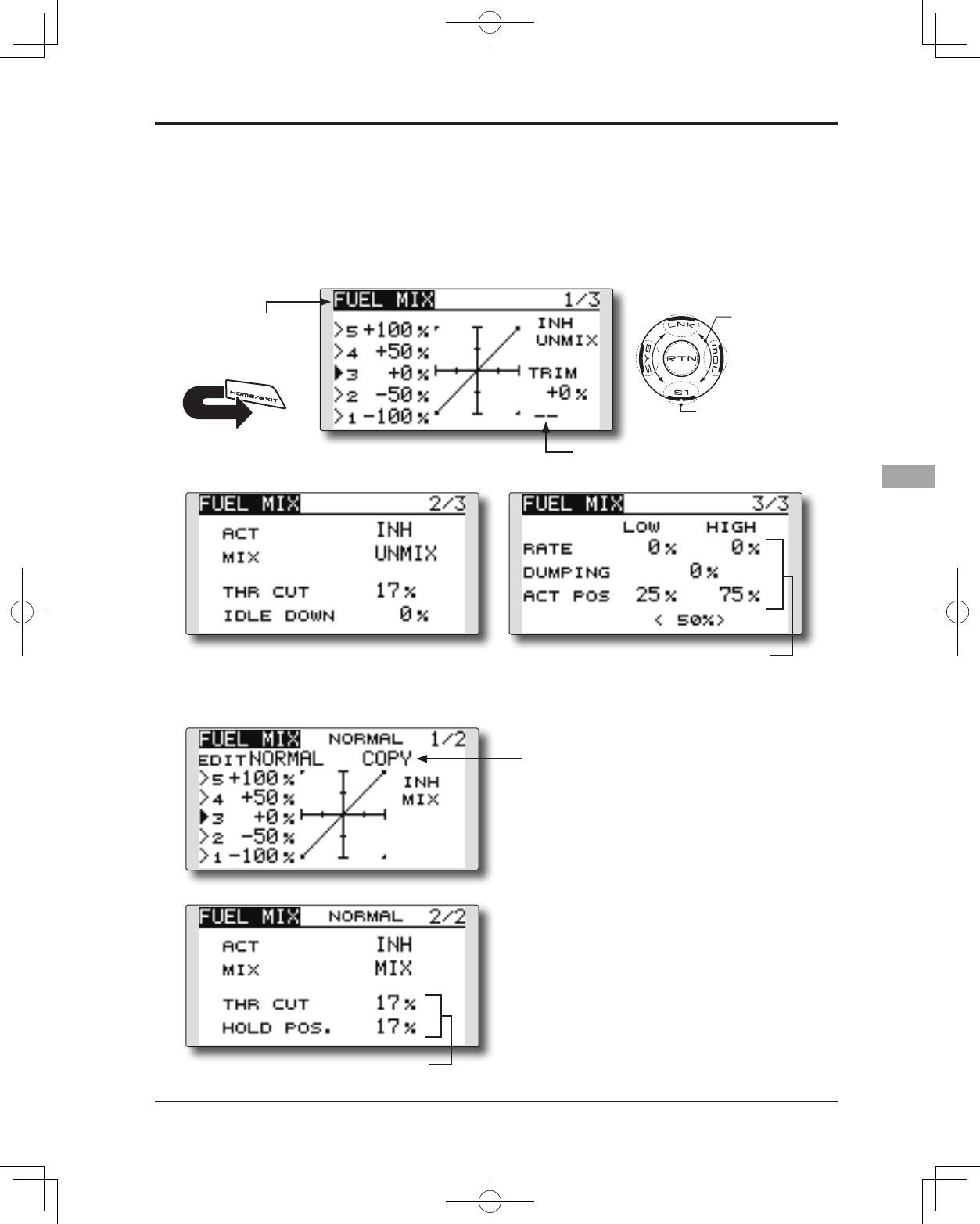
113
<Model Menu (Common Functions)>
● Select the function name
and return to the Model
menu by touching the
RTN button. Or the
HOME/EXIT button is
pushed.
<SensorTouch™>
RETURN
FUEL MIX Dedicated mixing used to adjust the fuel mixture of applicable
engines. [Airplane/helicopter]
This function is utilized to rene inight needle
adjustments of engines that offer mixture control
carburetors.
Note: Initial settings does not assign fuel mix to
any channel. Prior to utilizing the Fuel Mix
settings, select an unused channel on your
receiver and assign it accordingly for the
mixture control. Additionally, please make
sure that your [Control] and [Trim] are set to
null [--].
● Select [FUEL MIX] at the Model menu and
access the setup screen shown below by
touching the RTN button.
Scrolling
● Moving cursor
● Selecting mode
● Adjusting value
● To next page
●Acceleration setting
●Needle high trim
selection
[Airplane type]
[Helicopter type]
●Engine cut setting
●Mixing curve copy function
Move the COPY item and touch the RTN
button to switch to the data input mode.
Select the copy destination condition by
scrolling the touch sensor and touch the
RTN button. Select the [YES] and touch
the RTN button.
114 <Model Menu (Common Functions)>
reset to the initial value.)
Touch the RTN button to end adjustment and
return to the cursor mode.
*Needle high trim works as high trim based on the center.
(Works like ATL trim.)
●Acceleration setting (Airplane)
*This function is used to adjust the needle/engine rise
characteristics during acceleration. This enables an
acceleration function which temporarily increases the needle
operation from the throttle stick.
This function is used when there are symptoms of the
mixture being too lean or too rich, which would be
generated by sudden throttle stick inputs.
[Acceleration rate setting (RATE)]
*Acceleration can be adjusted for both high and low settings.
[Damping rate setting (DUMPING)]
*The return time after operation (Dumping) can be set.
Move the cursor to the rate item you want to
change and touch the RTN button to switch
to the data input mode.
Adjust the rate by scrolling the touch sensor.
*When the RTN button is touched for one second, the rate is
reset to the initial value.)
Touch the RTN button to end adjustment and
return to the cursor mode.
[Operation point setting (ACT POS)]
*The operation point at which the acceleration setting will
occur. If this point is exceeded, acceleration is performed.
Move the cursor to the [ACT POS] item and
hold the throttle stick to the position you
want to change and touch the RTN button
for one second.
Note: When using the acceleration function,
since the needle stroke is large, adjust your
settings so there is no binding of your linkage.
●Engine cut setting
* Operation linked with the throttle hold function, throttle cut
function, and idle down function is possible. The throttle cut
position can be adjusted accordingly. Set it to the full closed
position.
Move the cursor to the throttle cut or idle
down item and touch the RTN button to
switch to the data input mode.
Adjust the servo position by scrolling the
touch sensor.
Initial value: THR CUT: 17%, IDLE DOWN: 0%
Adjustment range: THR CUT: 0~50%, IDLE
DOWN: 0~100%
*When the RTN button is touched for one second, the rate is
reset to the initial value.)
Touch the RTN button to end the adjustment
and return to the cursor mode.
Setting method
*Before using this function, assign the [FUEL MIX] function
to an unused channel in the Linkage menu [FUNCTION] .
●Activate the function.
1. Move the cursor to the [ACT] item and touch
the RTN button to switch to the data input
mode.
Select the ACT mode by scrolling the touch
sensor.
*The display blinks.
Touch the RTN button to activate the
function and return to the cursor mode. (ON
is displayed.)
2. Move the cursor to the [MIX] item and touch
the RTN button to switch to the data input
mode.
Select the mixing mode you want to change
by scrolling the touch sensor.
*The display blinks.
Touch the RTN button to change the mode
and return to the cursor mode.
*When [MIX] is selected at the [MIX] icon, the throttle curve
data that is set becomes the mix master. When [UNMIX] is
selected, the throttle stick position becomes the master.
●5-point curve setting
1. Move the cursor to the point rate setting item
you want to adjust and touch the RTN button
to switch to the data input mode.
Adjust the rate by scrolling the touch sensor.
Initial value: 0%
Adjustment range: -100%~+100%
*When the RTN button is touched for one second, the servo
operation position is reset to the initial value.)
Touch the RTN button to end adjustment and
return to the cursor mode.
2. Repeat this procedure for each point.
●Needle high trim setting
1. Move the cursor to the needle high trim
selection item and access the switch setup
screen by touching the RTN button. Select
the needle high trim lever.
*For a detailed description of the setting method, see [Switch
Setting Method] at the back of this manual.
2. Move the cursor to the TRIM rate item and
touch the RTN button to switch to the data
input mode.
Adjust the trim rate by scrolling the touch
sensor.
Initial value: 0%
Adjustment range: -30%~+30%
*When the RTN button is touched for one second, the rate is
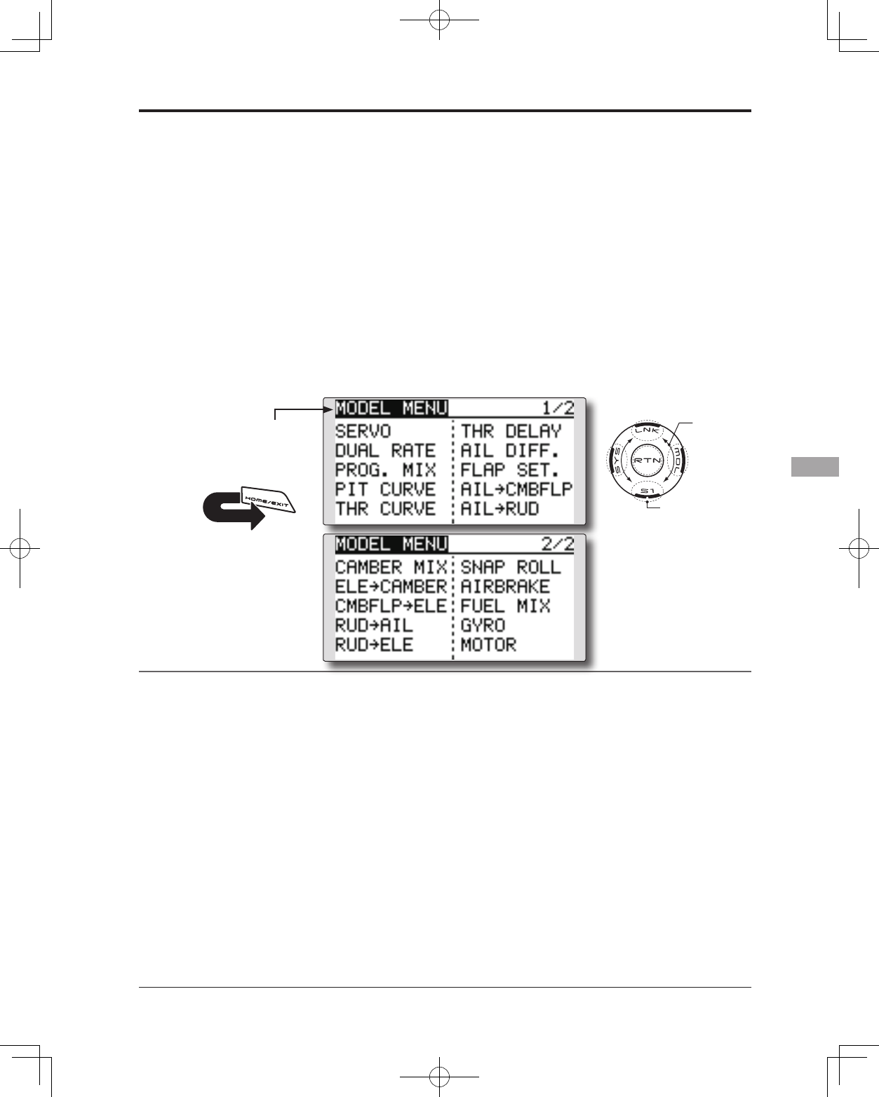
115
<Model Menu (Airplane/Glider Functions)>
MODEL MENU (AIRPLANE/GLIDER FUNCTIONS)
The dedicated mixes, etc. that are applicable
when an airplane or glider model type is selected
are displayed in this Model menu functions
section. Prior to adjusting any of these mixes, etc.
use the Model Type function in the Linkage menu
to select the model type, wing type, and tail type
matched to the aircraft. Other settings reset the
data used in mixing function, etc.
For glider, many dedicated mixes can be set
for each flight condition, as required. To switch
the settings for each condition by switch or stick
position, use the Condition Select function to add
flight conditions. (Up to five conditions can be
used)
Note: The T14SG is designed so that the airplane
and glider model types can utilize aircraft of the
same wing type.
The functions common to airplanes and gliders, with
the exception of some dedicated functions, are
written without regard to the model type.
While there may be differences, depending on the
number of servos, etc. the wing type used, etc. the
setup screens in the instruction manual are typical
examples.
Model Menu functions list
PITCH CURVE
Compatible with VPP (Variable Pitch Propeller)
function. [Airplane, general]
THR CURVE
THR curve function adjusts the throttle operation
curve for optimum engine speed to throttle stick
movement. [Airplane/glider, general]
THR DELAY
THR-DELAY function is used to slow the
response of the throttle stick to simulate the slow
response of a turbine engine, etc. [Airplane,
general]
AIL DIFFERENTIAL
The left and right aileron differential can be
adjusted independently. For glider, the differential
rate in buttery mixing can be adjusted.
[Airplane/glider, 2 ailerons or more]
FLAP SETTING
The up/down travel of each ap can be adjusted
independently for each servo according to the wing
type. [Airplane/glider, 2 aps or more]
AIL to CAMB.FLP
This mix operates the camber aps in the aileron
mode. It improves the roll axis characteristics.
[Airplane/glider, 2 ailerons + 2 aps or more]
AIL to BRKFLP
This mix operates the brake aps in the aileron
mode. It improves the roll axis characteristics.
[Glider, 4 aps]
*The Model menu screen depends on
the model type.
● Access the model menu shown below by
touching the MDL button twice at the home
screen, etc.
● Select the function name
and return to the Model
menu by touching the
RTN button. Or a HOME/
EXIT button is pushed.
<SensorTouch™>
● Select the function
you want to set and
access the setup
screen by touching
the RTN button.
Scrolling
● Moving
cursor
● To next page
RETURN
116 <Model Menu (Airplane/Glider Functions)>
AIL 3
(Chip Aileron) AIL 4
(Chip Aileron)
AIL1
(Main Aileron) AIL 2
(Main Aileron)
FLP 2
(Camber Flap)
FLP 1
(Camber Flap)
ELEVATOR
(ELEVATOR 2)
V-TAIL AILVATOR
FLP 3
(Brake Flap)
FLP 4
(Brake Flap) RUDDER 2
Winglet
RUDDER 1
RUDDER
(RUDDER 2)
Winglet
at Flying wing at Flying wing
( ) ( )
ELEVATOR ELEVATOR 2
(AILERON 5) (AILERON 6)
AIL to RUD
This mix is used when you want to coordinate
the rudder with aileron operation for banking at
shallow angles. [Airplane/glider, general]
RUD to AIL
This function is used when you want to mix
the ailerons with rudder input. Rudder is applied
during rolling maneuvers such as knife edge ight.
[Airplane/glider, general]
CAMBER MIX
This mix adjusts the camber and corrects the
elevators. [Airplane/glider, 2 ailerons or more]
ELE to CAMBER
This mix is used when you want to the mix
camber aps with elevator to increase the lift of the
model. [Airplane/glider, 2 ailerons or more]
CAMB.FLP to ELE
This mix is used to correct for changes in attitude
when the camber flaps are utilized. [Airplane/
glider, 2 ailerons + 1 ap or more]
BUTTERFLY (Crow)
This function is used to quickly slow the aircraft
and/or reduce the altitude. [Glider, 2 ailerons or
more (Flying: 2 ailerons + 1 ap or more)]
TRIM MIX
The ailerons, elevators, and aps trim offset rate
can be accessed by selecting a switch or condition
selection as desired. [Glider, 2 ailerons or more]
AIRBRAKE
This function is used when airbrakes are
necessary when landing or when diving, etc. during
ight. (Airplane, 2 ailerons or more)
GYRO
This is a dedicated mix when a GYA Series gyro
is used. [Airplane/glider, general]
V-TAIL
This function incorporates the elevators and
rudder input for use with V-tail models. [Airplane/
glider, V-tail specications]
AILEVATOR (DUAL ELEVATOR)
This function adjusts the elevators and ailerons
of models with elevator specifications. [Airplane/
glider, ailevator specications]
WINGLET
This function adjusts the left and right rudders
of winglet models. [Airplane/glider, winglet
specications]
MOTOR
This function adjusts the operation speed when
the motor of an F5B or other such EP glider is
started by a switch. [Airplane/glider, general]
RUD to ELE
This function is used to correct rolling maneuvers
such as, knife edge ight. [Airplane, general]
SNAP ROLL
This function selects the snap roll switch and
adjusts the amount of servo input. Servo speed can
also be adjusted. [Airplane general]
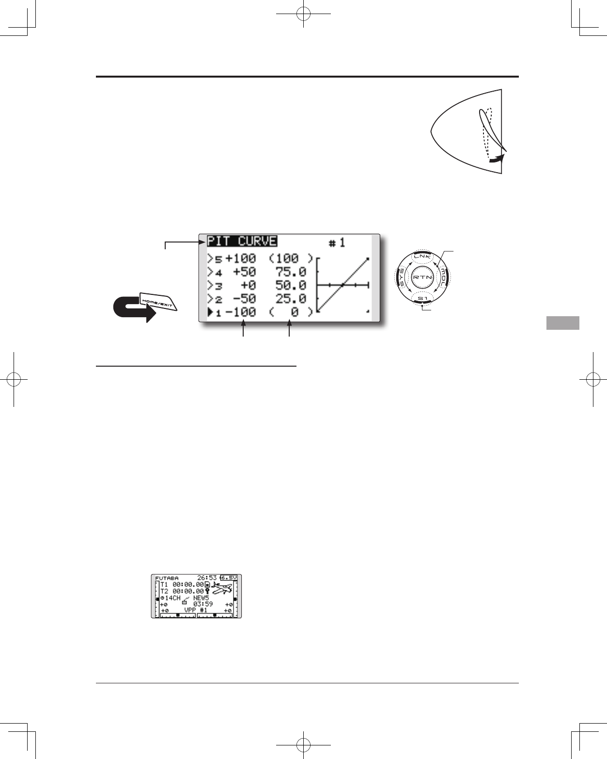
117
<Model Menu (Airplane/Glider Functions)>
● Select the function name
and return to the Model
menu by touching the
RTN button. Or the
HOME/EXIT button is
pushed.
<SensorTouch™>
RETURN
This function adjusts the pitch curve for VPP
(Variable Pitch Propeller) airplane.
*Up to 3 conditions can be set.
*The priority increases in condition 1→2→3 order.
NOTE: When VPP is not assigned to any
channel, the pitch curve is not displayed in
the model menu. In this case, assign VPP to
any channel on the function screen.
● Select [PIT CURVE] at the Model menu
and access the setup screen shown
below by touching the RTN button.
●Curve rate
Scrolling
● Moving cursor
● Selecting mode
● Adjusting value
● To next page
PIT CURVE [Corresponding model type]: Airplane, general
Setting method
●VPP condition selection
1. Move the cursor to the # button at the top
right side of the screen and touch the RTN
button to switch to the data input mode.
Select the VPP condition by scrolling the
touch sensor.
*The display blinks.
Touch the RTN button to call the setting
screen and return to the cursor mode.
2. Move the cursor to the switch item and
touch the RTN button to access the selection
screen. Select the switch and set its ON
direction.
*For a description of the switch selection method, see the
description at the back of this manual.
Set the VPP condition 2 and 3 switch.
*The VPP conditions can also be checked in the HOME
screen.
●5-point curve setting
[Curve rate setting]
1. Move the cursor to the curve rate setting
item you want to adjust and touch the RTN
button to switch to the data input mode.
Adjust the rate by scrolling the touch sensor.
Initial value: 0%
Adjustment range: 0%~100%
*When the RTN button is touched for one second, the rate is
reset to the initial value.
Touch the RTN button to end the adjustment
and return to the cursor mode.
2. Repeat this procedure for each point.
[Moving curve point]
1. Move the cursor to the curve point setting
item you want to adjust and touch the RTN
button to switch to the data input mode.
Adjust the curve point by scrolling the touch
sensor.
Initial value: P1: (0%), P2: 25%, P3: 50%, P4:
75%, P5: (100%)
Adjustment range: Up to 2.5% in front of the
adjoining point
*When the RTN button is touched for one second, the curve
position is reset to the initial value.)
Touch the RTN button to end the adjustment
and return to the cursor mode.
2. Repeat this procedure for each point.
[Deleting/returning curve point]
Move the cursor to the curve point setting
item you want to delete/return and touch
the RTN button for one second.
●Curve point
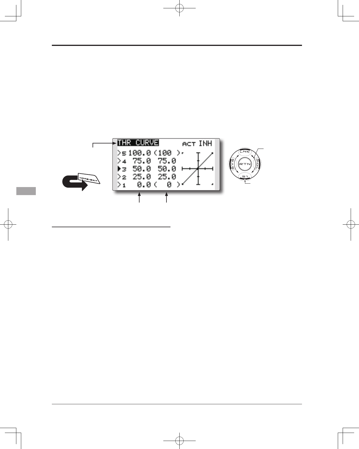
118 <Model Menu (Airplane/Glider Functions)>
● Select the function name
and return to the Model
menu by touching the
RTN button. Or the
HOME/EXIT button is
pushed.
<SensorTouch™>
RETURN
This function adjusts the throttle curve for
optimum engine speed from throttle stick input.
*When throttle curve is set to ON when there is no throttle
function; this curve acts as the motor function.
NOTE: If this throttle curve function is activated,
you can not use the THR-EXP function within
the DUAL RATE function simultaneously.
● Select [THR CURVE] at the Model menu
and access the setup screen shown
below by touching the RTN button.
●Curve rate
Scrolling
● Moving cursor
● Selecting mode
● Adjusting value
● To next page
THR CURVE [Corresponding model type]: Airplane/glider, general
Setting method
●Activate the function.
1. Move the cursor to the [ACT] item and touch
the RTN button to switch to the data input
mode.
Select the ON mode by scrolling the touch
sensor.
*The display blinks.
Touch the RTN button to activate the
function and return to the cursor mode.
●5-point curve setting
[Curve rate setting]
1. Move the cursor to the curve rate setting
item you want to adjust and touch the RTN
button to switch to the data input mode.
Adjust the rate by scrolling the touch sensor.
Initial value: 0%
Adjustment range: 0%~100%
*When the RTN button is touched for one second, the rate is
reset to the initial value.)
Touch the RTN button to end the adjustment
and return to the cursor mode.
2. Repeat this procedure for each point.
[Moving curve point]
1. Move the cursor to the curve point setting
item you want to adjust and touch the RTN
button to switch to the data input mode.
Adjust the curve point by scrolling the touch
sensor.
Initial value: P1: (0%), P2: 25%, P3: 50%, P4:
75%, P5: (100%)
Adjustment range: Up to 2.5% in front of the
adjoining point
*When the RTN button is touched for one second, the curve
position is reset to the initial value.)
Touch the RTN button to end the adjustment
and return to the cursor mode.
2. Repeat this procedure for each point.
[Deleting/returning curve point]
Move the cursor to the curve point setting
item you want to delete/return and touch
the RTN button for one second.
●Curve point
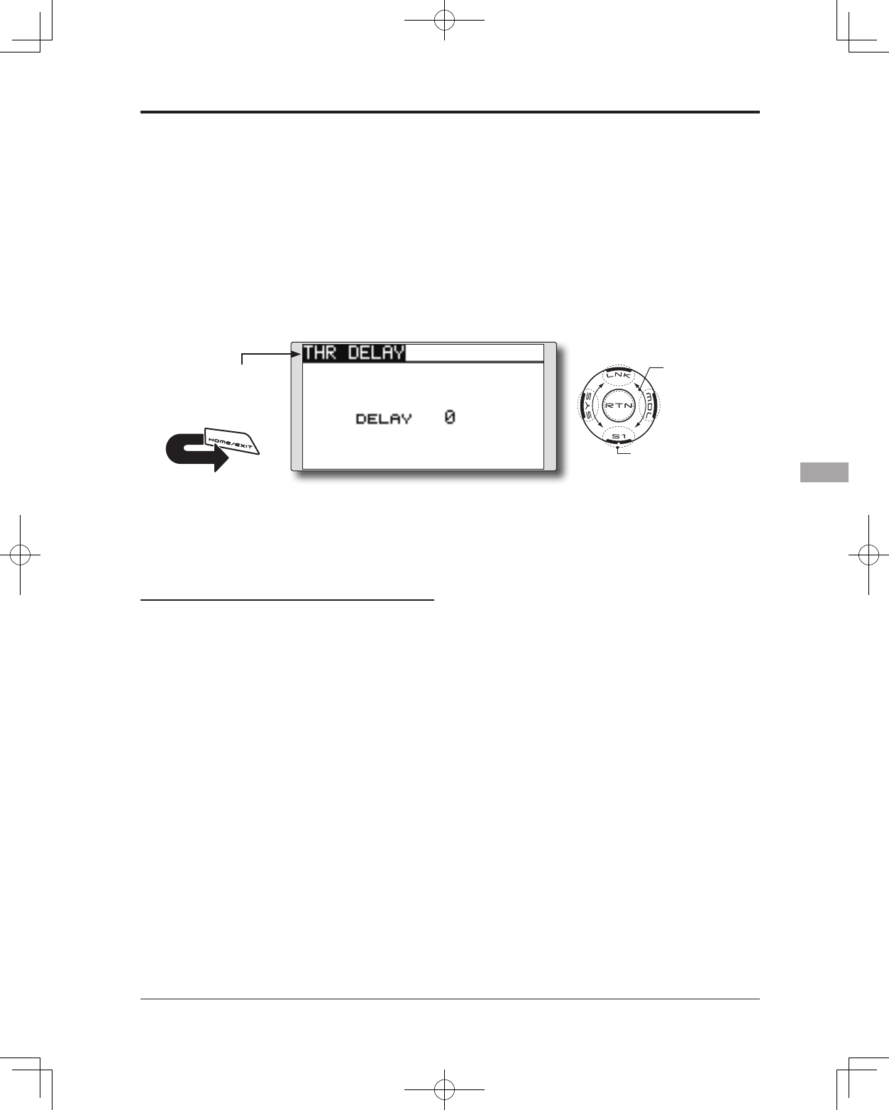
119
<Model Menu (Airplane/Glider Functions)>
● Select the function name
and return to the Model
menu by touching the
RTN button. Or the
HOME/EXIT button is
pushed.
<SensorTouch™>
RETURN
THR-DELAY function is used to slow the
response of the throttle stick to simulate the slow
response of a turbine engine, etc.
*This function is the same as THR of servo speed. If it sets up
in great numbers, it overlaps and a THR servo becomes late
further. Please do not let me overlap. Use either.
● Select [THR DELAY] at the Model menu
and access the setup screen shown
below by touching the RTN button.
Scrolling
● Moving cursor
● Selecting mode
● Adjusting value
● To next page
THR DELAY [Corresponding model type]: Airplane, general
Setting method
●Operation speed (delay) setting
1. Move the cursor to the [DELAY] item and
touch the RTN button to switch to the data
input mode.
Adjust the delay rate by scrolling the touch
sensor.
Initial value: 0
Adjustment range: 0~27 (maximum delay)
*When the RTN button is touched for one second, the rate is
reset to the initial value.)
Touch the RTN button to activate the
function and return to the cursor mode.
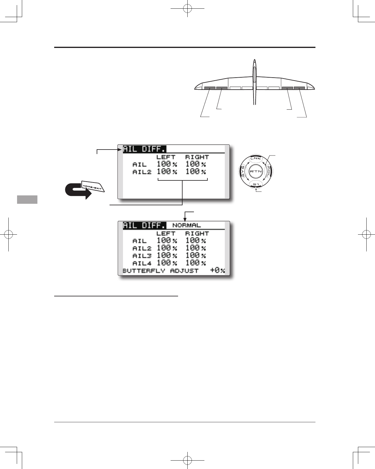
120 <Model Menu (Airplane/Glider Functions)>
● Select the function name
and return to the Model
menu by touching the
RTN button. Or the
HOME/EXIT button is
pushed.
<SensorTouch™>
RETURN
AIL 3
(Chip Aileron) AIL 4
(Chip Aileron)
AIL1
(Main Aileron) AIL 2
(Main Aileron)
AIL DIFF. [Corresponding model type]: Airplane/glider, 2 ailerons or more
The left and right aileron differential can be
adjusted independently.
For glider, the differential rate in buttery mixing
can be adjusted.
*The display screen is an example. The actual
screen depends on the Model Type.
Setting method
●Aileron left/right adjustment
Move the cursor to the aileron (AIL) 1~4 left (or
right) setting item and touch the RTN button
to switch to the data input mode.
Adjust the aileron angles by scrolling the
touch sensor when the stick is moved to the
left (or right) end.
Initial value: 100%
Adjustment range: 0~120%
*When the RTN button is touched for one second, the rate is
reset to the initial value.)
Touch the RTN button to end the adjustment
and return to the cursor mode.
(Currently selected condition name)
● Select [AIL DIFF.] at the Model menu
and access the setup screen shown
below by touching the RTN button.
Scrolling
● Moving cursor
● Selecting mode
● Adjusting value
● To next page
[Airplane (2A+2F)]
[Glider (4A+2F)]
● Aileron left/right
adjustment
●Aileron differential adjustment in buttery
mixing
Move the cursor to the [BUTTERFLY ADJUST]
item and touch the RTN button to switch to
the data input mode.
Adjust the differential rate by scrolling the
touch sensor.
Initial value: 0%
Adjustment range: -120~+120%
*When the RTN button is touched for one second, the rate is
reset to the initial value.)
Touch the RTN button to end the adjustment
and return to the cursor mode.
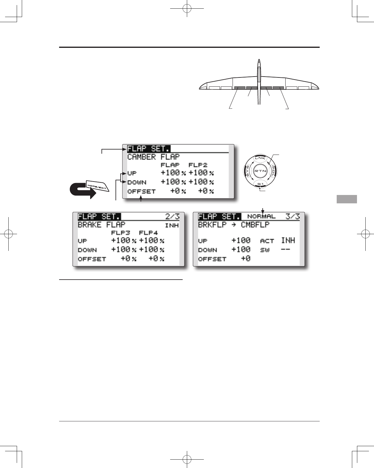
121
<Model Menu (Airplane/Glider Functions)>
● Select the function name
and return to the Model
menu by touching the
RTN button. Or the
HOME/EXIT button is
pushed.
<SensorTouch™>
RETURN
FLP 2
(Camber Flap)
FLP 1
(Camber Flap)
FLP 3
(Brake Flap) FLP 4
(Brake Flap)
FLAP SET. [Corresponding model type]: Airplane/glider, 2 aps or more
The up/down travel of each ap (camber aps:
FLP1/2, brake flaps: FLP3/4) can be adjusted
independently for each servo according to the
wing type.
● The operation reference point of each ap can be
offset
The camber flaps of a 4-flap model can
be mixed with the brake flaps. (BRKFLP to
CMBFLP)
● An ON/OFF switch can be set.
*The display screen is an example. The actual
screen depends on the model type.
Setting method
●Flap up/down adjustment
Move the cursor to the flap (FLP) 1~4 Up or
Down item according to the wing type and
touch the RTN button to switch to the data
input mode. Adjust the travel independently
by scrolling the touch sensor.
Initial value: +100%
Adjustment range: -120~+120%
*When the RTN button is touched for one second, the rate is
reset to the initial value.)
Touch the RTN button to end the adjustment
and return to the cursor mode.
●Reference point adjustment
Move the cursor to the [OFFSET] item and
touch the RTN button to switch to the data
input mode. Adjust the operation reference
point of each flap by scrolling the touch
sensor.
Initial value: 0%
Adjustment range: -100~+100%
*When the RTN button is touched for one second, the
reference point is reset to the initial value.)
Touch the RTN button to end the adjustment
and return to the cursor mode.
●Activate the Brake FLP to Camber FLP mixing
Move the cursor to the [ACT] item and touch
the RTN button to switch to the data input
mode. Select the ACT mode by scrolling the
touch sensor.
*The display blinks.
Touch the RTN button to activate the
function and return to the cursor mode. (ON
is displayed.)
To select a switch, move the cursor to the
[SW] item and touch the RTN button to call
the selection screen. Select the switch and
set its ON direction. (Always ON at "--" setting)
*For a description of the switch selection method, see the
description at the back of this manual.
● Select [FLAP SET.] at the Model menu and access the setup
screen shown below by touching the RTN button.
Scrolling
● Moving cursor
● Selecting mode
● Adjusting value
● To next page
(Glider: Currently selected condition name)
●Operation reference
point offset
●Up /Down
adjustment
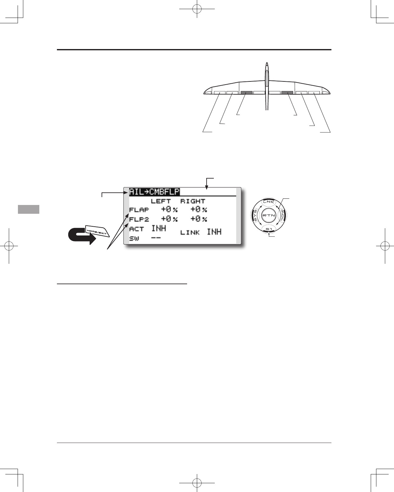
122 <Model Menu (Airplane/Glider Functions)>
● Select the function name
and return to the Model
menu by touching the
RTN button. Or the
HOME/EXIT button is
pushed.
<SensorTouch™>
RETURN
AIL 3
(Chip Aileron) AIL 4
(Chip Aileron)
AIL1
(Main Aileron) AIL 2
(Main Aileron)
FLP 2
(Camber Flap)
FLP 1
(Camber Flap)
AIL to CMBFLP [Corresponding model type]: Airplane/glider, 2 ailerons + 2 flaps or
more
This mix operates the camber flaps (FLP1/2)
in the aileron mode. When the aileron stick
is manipulated, the ailerons and camber flaps
perform aileron operation simultaneously to
signicantly improve the roll axis.
● The aileron left/right mixing rate of each ap servo
can be independently adjusted.
● An ON/OFF switch can be set.
● Linking is possible: Link this mix to other mixes.
● Adjustment of each
ap servo
Setting method
●Activate the function
Move the cursor to the [ACT] item and touch
the RTN button to switch to the data input
mode. Select the ACT mode by scrolling the
touch sensor.
*The display blinks.
Touch the RTN button to activate the
function and return to the cursor mode. (ON
is displayed.)
When selecting a switch, move the cursor to
the [SW] item and touch the RTN button to
call the selection screen. Select the switch
and set its ON direction. (Always ON at "--"
setting)
*For a description of the switch selection method, see the
description at the back of this manual.
●Mixing rate adjustment
Move the cursor to the flap (FLP) 1~2 left
or right item according to the wing type
and touch the RTN button to switch to the
data input mode. Adjust the mixing rate
independently by scrolling the touch sensor.
Initial value: 0%
Adjustment range: -120~+120%
*When the RTN button is touched for one second, the rate is
reset to the initial value.)
Touch the RTN button to end the adjustment
and return to the cursor mode.
●Link mode setting
When linking a mix, move the cursor to the
[LINK] item and touch the RTN button to
switch to the data input mode. Select the
ON mode by scrolling the touch sensor.
*The display blinks.
Touch the RTN button to set the link mode
and return to the cursor mode.
● Select [AIL to CMBFLP] at the Model
menu and access the setup screen
shown below by touching the RTN
button.
*The display screen is an example. The actual
screen depends on the model type.
Scrolling
● Moving cursor
● Selecting mode
● Adjusting value
● To next page
(Glider: Currently selected condition name)
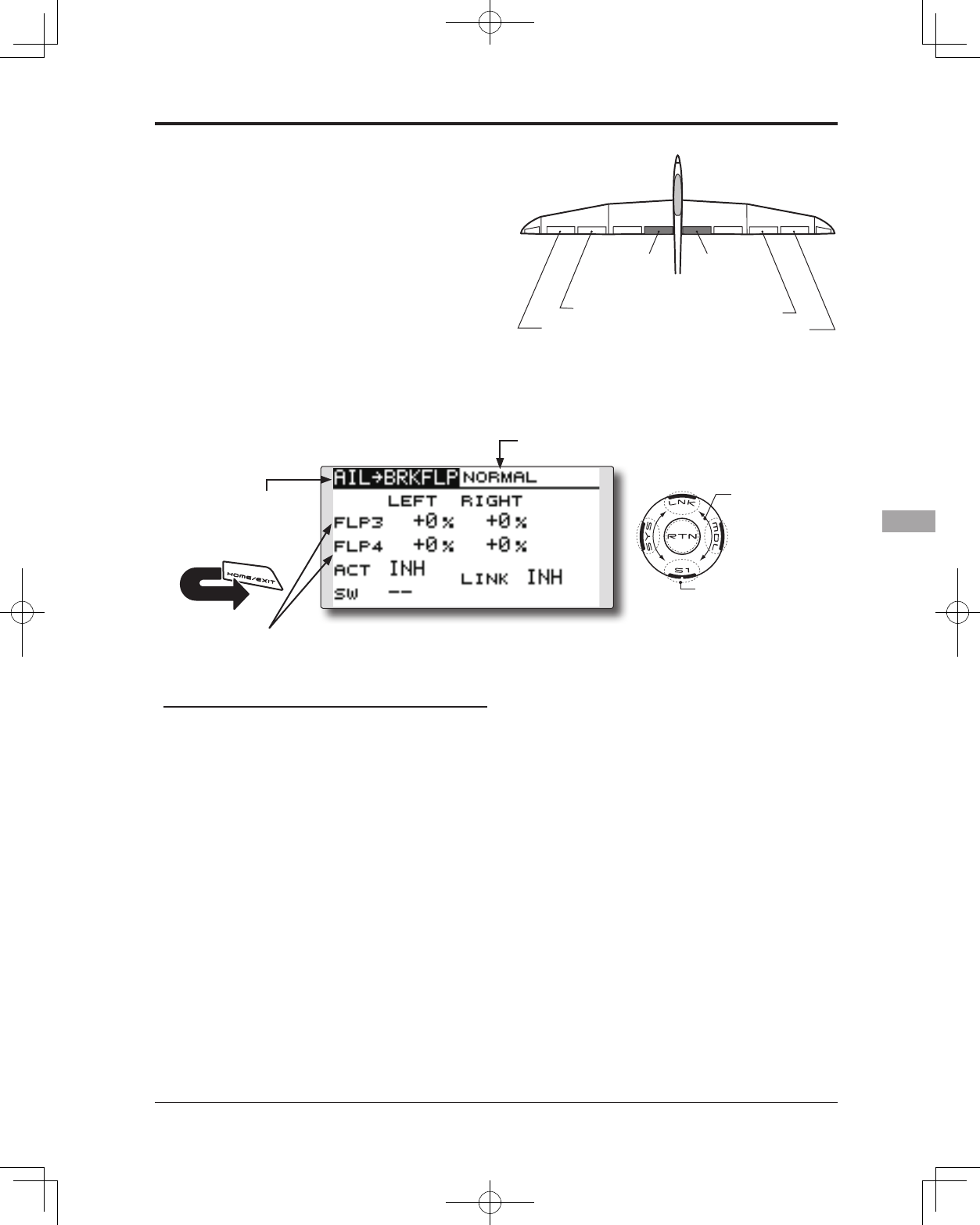
123
<Model Menu (Airplane/Glider Functions)>
● Select the function name
and return to the Model
menu by touching the
RTN button. Or the
HOME/EXIT button is
pushed.
<SensorTouch™>
RETURN
AIL 3
(Chip Aileron) AIL 4
(Chip Aileron)
AIL1
(Main Aileron) AIL 2
(Main Aileron)
FLP 3
(Brake Flap) FLP 4
(Brake Flap)
AIL to BRAKEFLP [Corresponding model type]: Glider, 4 aps
This mix operates the brake flaps (FLP3/4)
in the aileron mode. When the aileron stick is
manipulated, the aileron and brake aps perform
the aileron operation simultaneously and the roll
axis is improved.
● The aileron left and right mixing rates can be
adjusted separately for each ap servo.
● Mixing during flight can be turned ON/OFF by
setting a switch. (Always ON at [--] setting)
● Linking can be set: Link this mix to other mixes.
● Select [AIL to BRKFLP] at the Model
menu and access the setup screen
shown below by touching the RTN
button.
Scrolling
● Moving cursor
● Selecting mode
● Adjusting value
● To next page
● Adjustment of each
ap servo
*The display screen is an example. The actual
screen depends on the model type.
(Currently selected condition name)
Setting method
●Activate the function
Move the cursor to the [ACT] item and touch
the RTN button to switch to the data input
mode. Select the ACT mode by scrolling the
touch sensor.
*The display blinks.
Touch the RTN button to activate the
function and return to the cursor mode. (ON
is displayed.)
When setting a switch, move the cursor to
the [SW] item and touch the RTN button
to access the selection screen. Select the
switch and set its ON direction. (Always ON
at "--" setting)
*For a description of the switch selection method, see the
description at the back of this manual.
●Mixing rate adjustment
Move the cursor to the flap (FLP) 3~4 left or
right item and touch the RTN button to switch
to the data input mode. Adjust the mixing
rate independently by scrolling the touch
sensor.
Initial value: 0%
Adjustment range: -120~+120%
*When the RTN button is touched for one second, the rate is
reset to the initial value.)
Touch the RTN button to end the adjustment
and return to the cursor mode.
●Link mode setting
To activate the mixing, move the cursor to
the [LINK] item and touch the RTN button to
switch to the data input mode. Select the
ON mode by scrolling the touch sensor.
*The display blinks.
Touch the RTN button to set the link mode
and return to the cursor mode.
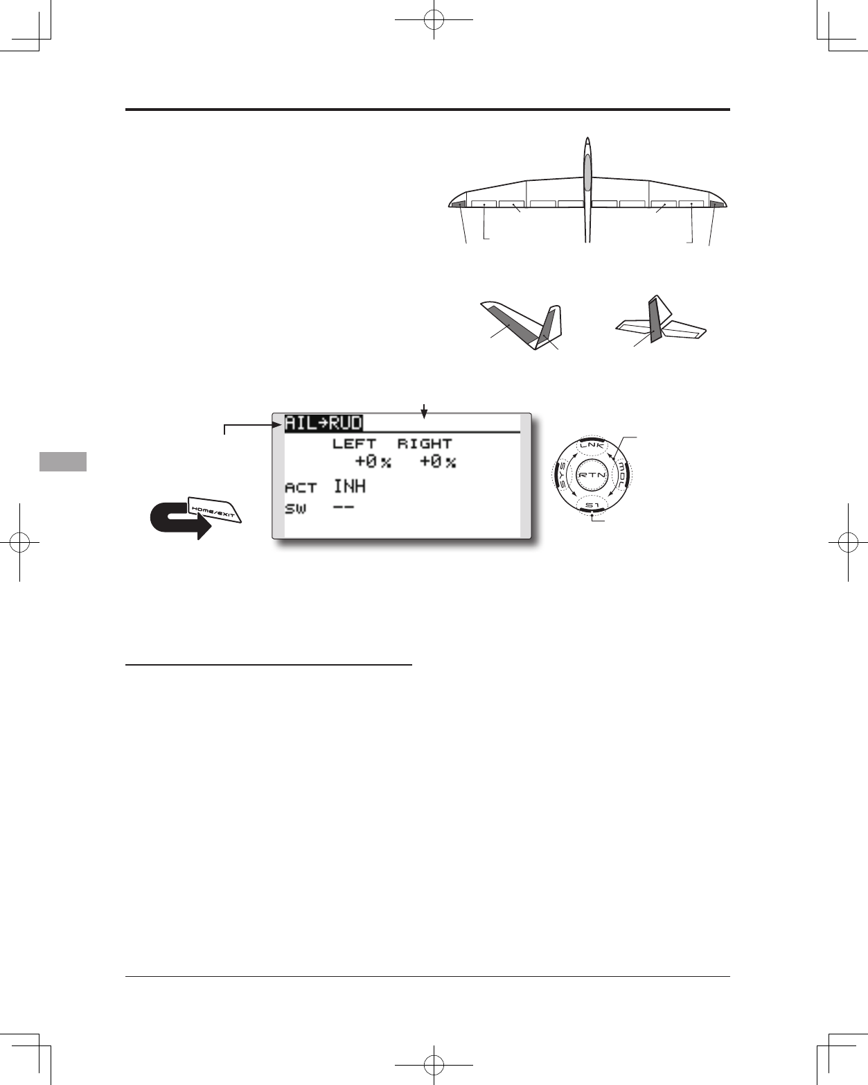
124 <Model Menu (Airplane/Glider Functions)>
● Select the function name
and return to the Model
menu by touching the
RTN button. Or the
HOME/EXIT button is
pushed.
<SensorTouch™>
RETURN
RUDDER 2
RUDDER RUDDER
V-TAIL
RUDDER 2
Winglet
RUDDER 1
Winglet
at Flying wing at Flying wing
( ) ( )
AIL 3 AIL 3
(Chip Aileron) (Chip Aileron)
AIL1
(Main Aileron) AIL 2
(Main Aileron)
AIL to RUD [Corresponding model type]: Airplane/glider, general
Use this mix when you want to mix the rudders
with aileron operation. This allows the aircraft to
bank at a steep angle.
● Mixing during flight can be turned ON/OFF by a
switch. (Always ON at [--] setting)
● The mixing rate can be adjusted.
● Select [AIL to RUD] at the
Model menu and access the
setup screen shown below by
touching the RTN button.
*The display screen is an example.
The actual screen depends on the
model type.
Scrolling
● Moving cursor
● Selecting mode
● Adjusting value
● To next page
(Glider: Currently selected condition name)
Setting method
●Activate the function
Move the cursor to the [ACT] item and touch
the RTN button to switch to the data input
mode. Select the ACT mode by scrolling the
touch sensor.
*The display blinks.
Touch the RTN button to activate the
function and return to the cursor mode. (ON
is displayed.)
When selecting a switch, move the cursor to
the [SW] item and touch the RTN button to
call the selection screen. Select the switch
and set its ON direction. (Always ON at "--"
setting)
*For a description of the switch selection method, see the
description at the back of this manual.
●Mixing rate adjustment
Move the cursor to the left or right item
and touch the RTN button to switch to the
data input mode. Adjust the mixing rate
independently by scrolling the touch sensor.
Initial value: 0%
Adjustment range: -100~+100%
*When the RTN button is touched for one second, the rate is
reset to the initial value.)
Touch the RTN button to end the adjustment
and return to the cursor mode.
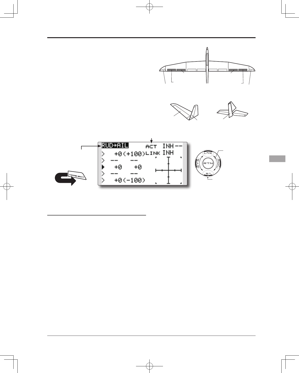
125
<Model Menu (Airplane/Glider Functions)>
● Select the function name
and return to the Model
menu by touching the
RTN button. Or the
HOME/EXIT button is
pushed.
<SensorTouch™>
RETURN
RUDDER 2
RUDDER RUDDER
V-TAIL
RUDDER 2
Winglet
RUDDER 1
Winglet
at Flying wing at Flying wing
( ) ( )
AIL 3 AIL 3
(Chip Aileron) (Chip Aileron)
AIL1
(Main Aileron) AIL 2
(Main Aileron)
RUD to AIL [Corresponding model type]: Airplane/glider, general
This function is used when you want to mix
the ailerons with rudder input. It is used when
rudder is applied during roll maneuvers such
as, knife edge flight. It can be used to turn or
bank scale models, large models, etc. like a full-
size aircraft.
● Mixing during flight can be turned ON/OFF by
setting a switch. (Always ON at [--] setting)
● Linking can be set: Link this mix to other mixes.
● The mixing rate can also be adjusted.
● A 5-point curve can be set at airplane model type.
● Select [RUD to AIL] at the Model
menu and access the setup screen
shown below by touching the RTN
button.
*The display screen is an example.
The actual screen depends on the
model type.
Scrolling
● Moving cursor
● Selecting mode
● Adjusting value
● To next page
Setting method
●Activate the function
Move the cursor to the [ACT] item and touch
the RTN button to switch to the data input
mode. Select the ACT mode by scrolling the
touch sensor.
*The display blinks.
Touch the RTN button to activate the
function and return to the cursor mode. (ON
is displayed.)
When setting a switch, move the cursor to
the [SW] item and touch the RTN button to
call the selection screen. Select the switch
and set its ON direction. (Always ON at "--"
setting)
*For a description of the switch selection method, see the
description at the back of this manual.
●Mixing rate adjustment (glider)
Move the cursor to the left or right item
and touch the RTN button to switch to the
data input mode. Adjust the mixing rate
independently by scrolling the touch sensor.
Initial value: 0%
Adjustment range: -100~+100%
*When the RTN button is touched for one second, the rate is
reset to the initial value.)
Touch the RTN button to end the adjustment
and return to the cursor mode.
●Link mode setting
To activate the link mixing, move the cursor
to the [LINK] item and touch the RTN button
to switch to the data input mode. Select the
ON mode by scrolling the touch sensor.
*The display blinks.
Touch the RTN button to set the link mode
and return to the cursor mode.
(Glider: Currently selected condition name)
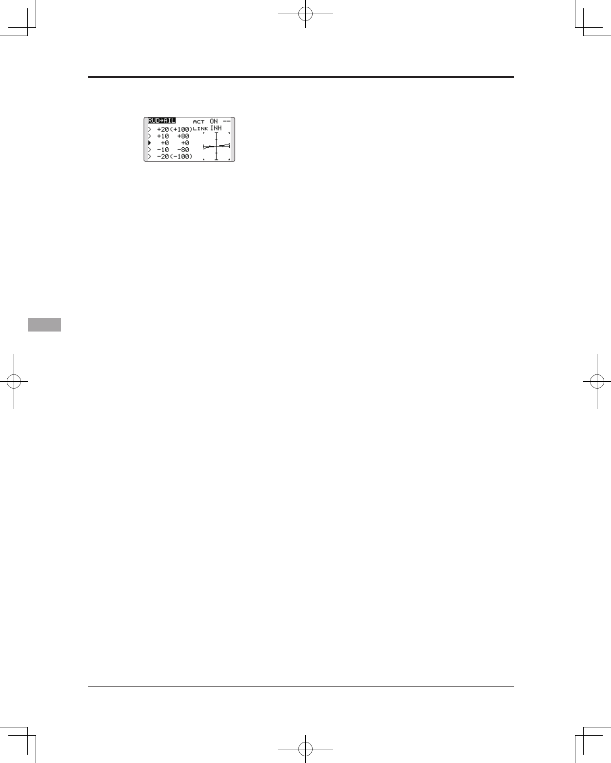
126 <Model Menu (Airplane/Glider Functions)>
●5-point curve setting (airplane)
[Curve rate setting]
1. Move the cursor to the curve rate setting
item (left side) you want to adjust and touch
the RTN button to switch to the data input
mode.
Adjust the rate by scrolling the touch sensor.
Adjustment range: -100%~+100%
*When the RTN button is touched for one second, the rate is
reset to the initial value.)
Touch the RTN button to end the adjustment
and return to the cursor mode.
2. Repeat this procedure for each point.
[Moving curve point]
1. Move the cursor to the curve point setting
item you want to adjust and touch the RTN
button to switch to the data input mode.
Adjust the curve point by scrolling the touch
sensor.
Adjustment range: Up to 2.5% in front of the
adjoining point
*When the RTN button is touched for one second, the curve
position is reset to the initial value.)
Touch the RTN button to end the adjustment
and return to the cursor mode.
2. Repeat this procedure for each point.
[Deleting/returning curve point]
Move the cursor to the curve point setting
item you want to delete/return and touch
the RTN button for one second.
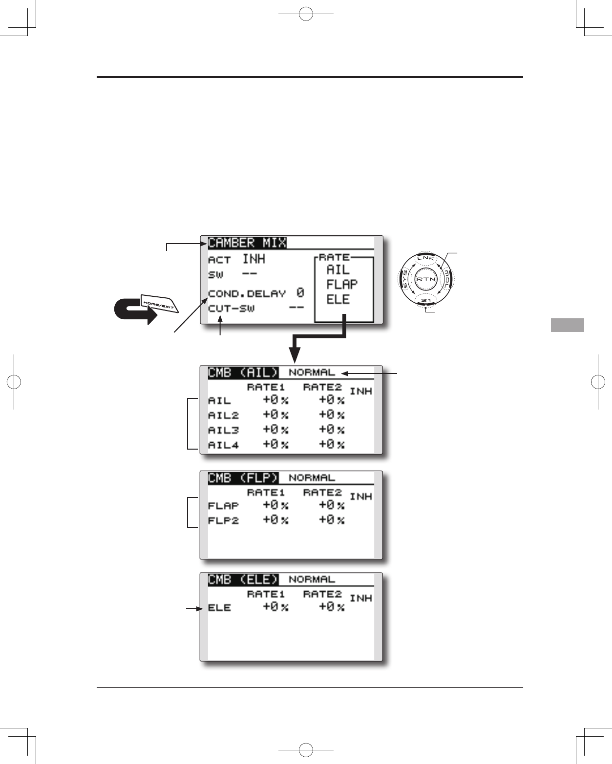
127
<Model Menu (Airplane/Glider Functions)>
● Select the function name
and return to the Model
menu by touching the
RTN button. Or the
HOME/EXIT button is
pushed.
<SensorTouch™>
RETURN
CAMBER MIX [Corresponding model type]: Airplane/glider, 2 ailerons or more
This function adjusts the rate of camber
operation for the wing camber (ailerons, camber
flaps, brake flaps) in the negative and positive
directions. The aileron, flap, and elevator rates
can also be adjusted independently and attitude
changes caused by camber operation can be
corrected.
*Initial setting assigns camber operation to side lever LS.
● The up/down rates of the aileron, flap, and
elevator servos can be adjusted. When the mixing
direction is reversed by the linkage, adjustments
can be made by changing the mixing rate
polarity (+ or -).
● Mixing during flight can be turned ON/OFF by
setting a switch. (Always ON at [--] setting)
● A condition delay can be set. A cut switch which
can turn OFF the delay function can be set.
●Condition delay
cut switch
●Condition delay
setting
●Aileron rate
adjustment
(Glider: Currently selected
condition name)
● Select [CAMBER MIX] at the Model
menu and access the setup screen
shown below by touching the RTN
button.
*The display screen is an example. The actual
screen depends on the model type.
Scrolling
● Moving cursor
● Selecting mode
● Adjusting value
● To next page
●Flap rate
adjustment
●Elevator rate
adjustment
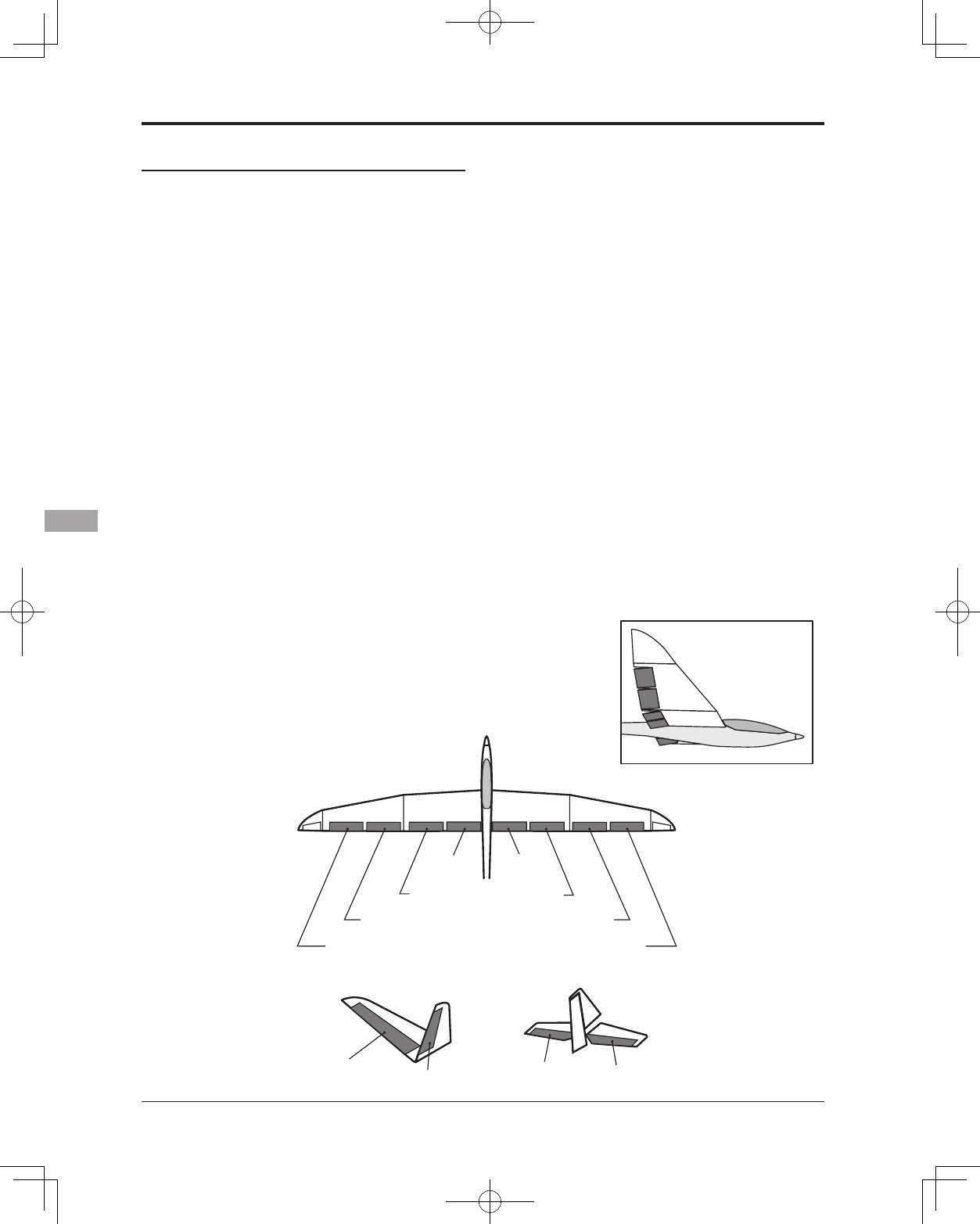
128 <Model Menu (Airplane/Glider Functions)>
AIL 3
(Chip Aileron) AIL 4
(Chip Aileron)
AIL1
(Main Aileron) AIL 2
(Main Aileron)
FLP 2
(Camber Flap)
FLP 1
(Camber Flap)
ELEVATOR ELEVATOR 2
V-TAIL
ELEVATOR ELEVATOR 2
AILVATOR
FLP 3
(Brake Flap) FLP 4
(Brake Flap)
Setting method
●Activate the function
Move the cursor to the [ACT] item and touch
the RTN button to switch to the data input
mode. Select the ACT mode by scrolling the
touch sensor.
*The display blinks.
Touch the RTN button to activate the
function and return to the cursor mode. (ON
is displayed.)
When setting a switch, move the cursor to
the [SW] item and touch the RTN button to
call the selection screen. Select the switch
and set its ON direction. (Always ON at "--"
setting)
*For a description of the switch selection method, see the
description at the back of this manual.
●Condition delay setting
Move the cursor to the [COND.DELAY] item
and touch the RTN button to switch to the
data input mode. Adjust the condition delay
by scrolling the touch sensor.
Initial value: 0
Adjustment range: 0~27
*When the RTN button is touched for one second, the rate is
reset to the initial value.)
Touch the RTN button to end the adjustment
and return to the cursor mode.
When setting a cut switch, move the cursor
to the [CUT-SW] item and touch the RTN
button to access the selection screen. Select
the switch and set its ON direction. (Always
ON at "--" setting)
*For a description of the switch selection method, see the
description at the back of this manual.
●Rate adjustment
The rates are adjusted by accessing the
aileron, ap, and elevator rate screens.
Move the cursor to the rate1 or rate2
item and touch the RTN button to switch
to the data input mode. Adjust the rate
independently by scrolling the touch sensor.
Initial value: 0%
Adjustment range: -100~+100%
*When the RTN button is touched for one second, the rate is
reset to the initial value.)
Touch the RTN button to end the adjustment
and return to the cursor mode.
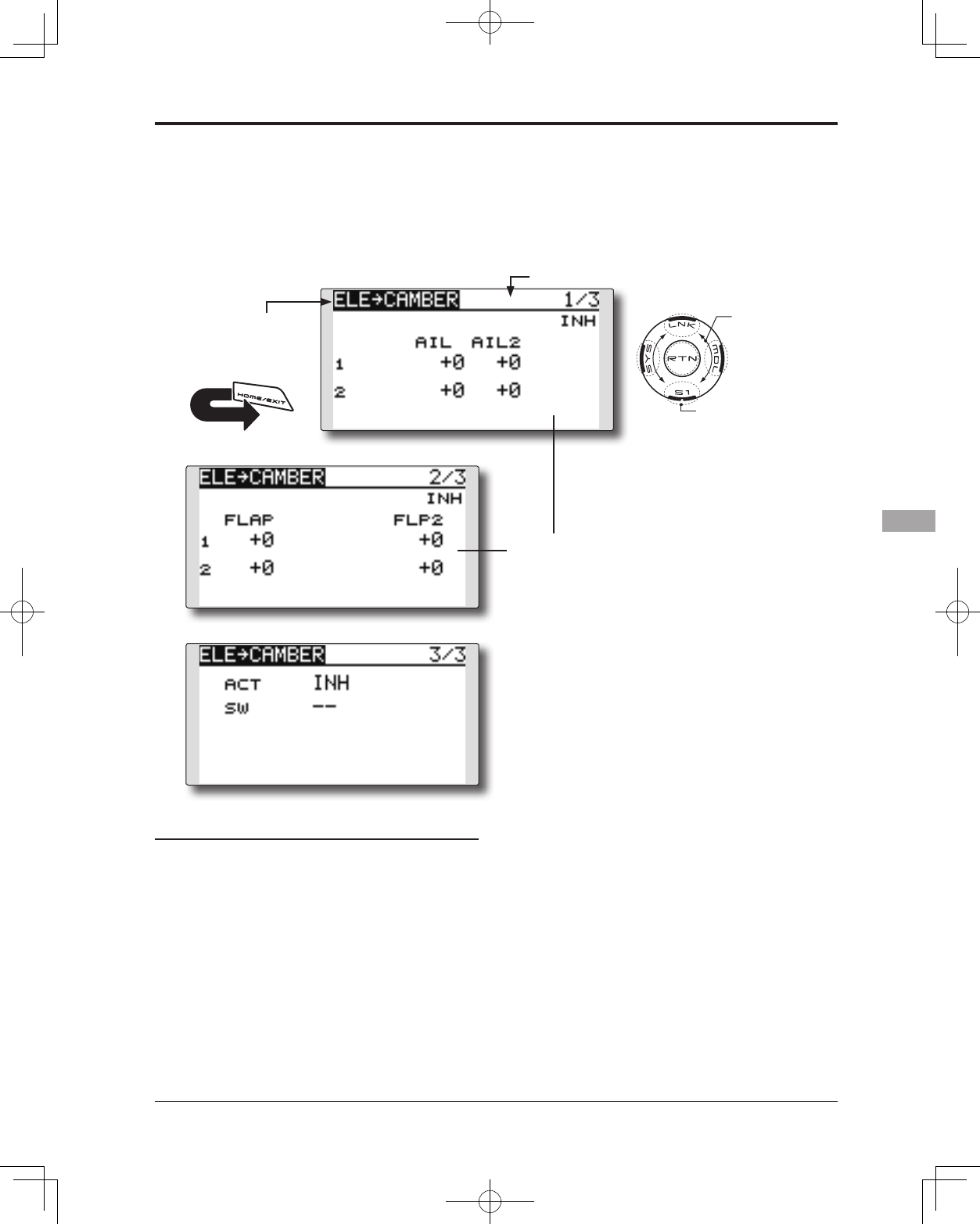
129
<Model Menu (Airplane/Glider Functions)>
● Select the function name
and return to the Model
menu by touching the
RTN button. Or the
HOME/EXIT button is
pushed.
<SensorTouch™>
RETURN
ELE to CAMBER [Corresponding model type]: Airplane/glider, 2 ailerons or more
This function is used when you want to mix the
camber aps with elevator operation. When used,
the flaps are lowered by up elevator, and lift is
increased.
● In-ight mixing can be turned ON/OFF by assigning
this to a switch. (Always ON at [--] setting)
● The mixing rate can be adjusted.
● The point that has little effect near the neutral
position of the elevator stick can be adjusted.
(Glider only)
Note: The elevator on the tailless wing will also
be effected when this mix is activated.
●Mixing rate adjustment
Move the cursor to the up or down mixing
rate item for each servo and touch the RTN
button to switch to the data input mode.
Adjust the rate independently by scrolling
the touch sensor.
Initial value: 0%
Adjustment range: -100~+100%
*When the RTN button is touched for one second, the rate is
reset to the initial value.)
Touch the RTN button to end the adjustment
and return to the cursor mode.
Setting method
●Activate the function
Move the cursor to the [ACT] item and touch
the RTN button to switch to the data input
mode. Select the ACT mode by scrolling the
touch sensor.
*The display blinks.
Touch the RTN button to activate the
function and return to the cursor mode. (ON
is displayed.)
When setting a switch, move the cursor to
the [SW] item and touch the RTN button to
call the selection screen. Select the switch
and set its ON direction. (Always ON at "--"
setting)
*For a description of the switch selection method, see the
description at the back of this manual.
●Range setting (Glider only)
Move the cursor to the [RANGE] item and
hold the elevator stick to the desired position
(upper or lower side) and then touch the RTN
button for one second to set the range.
*The mixing does not work near neutral of the elevator stick.
Initial value: 0%
Adjustment range: 0~100%
(Glider: Currently selected condition name)
● Select [ELE to CAMBER] at the Model menu
and access the setup screen shown below
by touching the RTN button.
*The display screen is an example.
The actual screen depends on the
model type.
Scrolling
● Moving cursor
● Selecting mode
● Adjusting value
● To next page
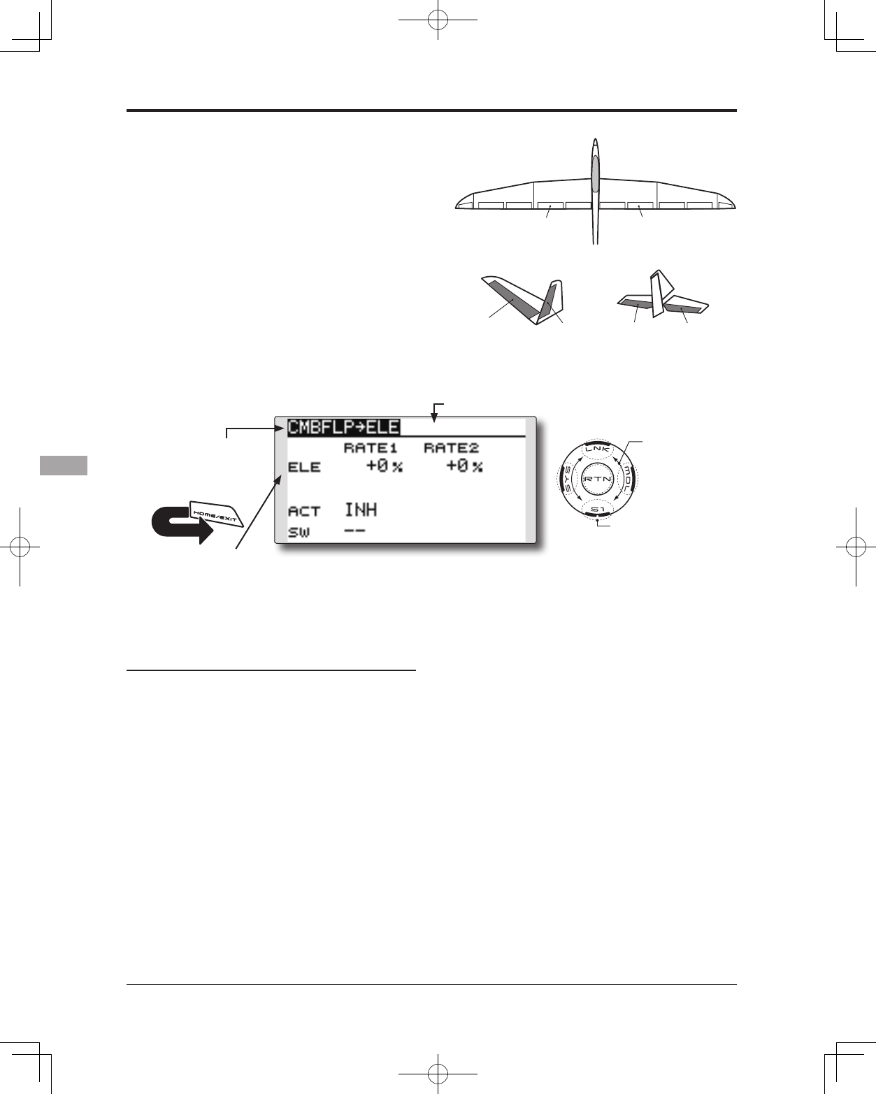
130 <Model Menu (Airplane/Glider Functions)>
● Select the function name
and return to the Model
menu by touching the
RTN button. Or the
HOME/EXIT button is
pushed.
<SensorTouch™>
RETURN
ELEVATOR ELEVATOR 2
V-TAIL
ELEVATOR ELEVATOR 2
AILVATOR
FLP 2
(Camber Flap)
FLP 1
(Camber Flap)
CMBFLP to ELE [Corresponding model type]: Airplane/glider,
2 ailerons + 1 ap or more
When the camber/speed flaps are utilized,
the aircraft might experience, a change in pitch.
This mix compensates for such changes by
incorporating elevator input.
● The elevator servos up/down rates can be
adjusted separately. If the mixing direction is
reversed, change the mixing rate polarity (+ or –).
● Mixing during flight can be turned ON/OFF by
setting a switch. (Always ON at [--] setting)
●Elevator rate
adjustment
Setting method
●Activate the function
Move the cursor to the [ACT] item and touch
the RTN button to switch to the data input
mode. Select the ACT mode by scrolling the
touch sensor.
*The display blinks.
Touch the RTN button to activate the
function and return to the cursor mode. (ON
is displayed.)
When setting a switch, move the cursor to
the [SW] item and touch the RTN button to
call the selection screen. Select the switch
and set its ON direction. (Always ON at "--"
setting)
*For a description of the switch selection method, see the
description at the back of this manual.
●Mixing rate adjustment
Move the cursor to the RATE1 or RATE2 item
and touch the RTN button to switch to the
data input mode. Adjust the mixing rate
independently by scrolling the touch sensor.
Initial value: 0%
Adjustment range: -120~+120%
*When the RTN button is touched for one second, the rate is
reset to the initial value.)
Touch the RTN button to end the adjustment
and return to the cursor mode.
● Select [CMBFLP to ELE] at the Model menu and
access the setup screen shown below by touching
the RTN button.
*The display screen is an
example. The actual screen
depends on the model type.
Scrolling
● Moving cursor
● Selecting mode
● Adjusting value
● To next page
(Glider: Currently selected condition name)
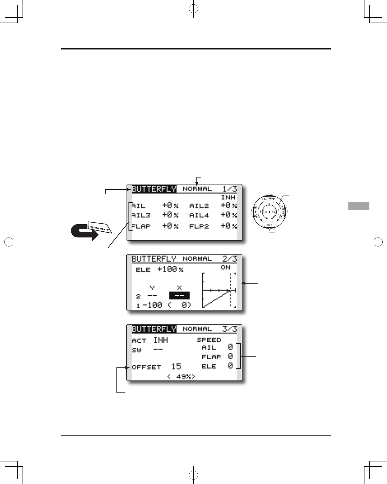
131
<Model Menu (Airplane/Glider Functions)>
● Select the function name
and return to the Model
menu by touching the
RTN button. Or the
HOME/EXIT button is
pushed.
<SensorTouch™>
RETURN
BUTTERFLY [Corresponding model type]: Glider, Normal: 2 ailerons or more
Flying: 2 ailerons + 1 ap or more
This function is utilized to quickly slow the
aircraft and reduce altitude by simultaneously
raising the left and right ailerons and lowering the
aps (camber ap, brake ap).
Butterfly (Crow) produces an extremely
efcient landing conguration by accomplishing
the following:
1. Slow the aircraft’s velocity.
2. Provide washout at the wing tips to reduce
the tendency to tip stall.
3. Create more lift toward the center of the
wing allowing it to y at a slower speed
● Mixing during flight can be turned ON/OFF by
setting a switch. (Always ON at [--] setting)
● The point at which the butterfly operation
reference point can be offset.
● The operational speed of the ailerons and flaps
can be adjusted.
● The differential rate can be adjusted.
*For a description of the setting method, see the aileron
differential function.
●Buttery operation reference point
● Select [BUTTERFLY] at the Model menu
and access the setup screen shown
below by touching the RTN button.
*The display screen is an example. The actual
screen depends on the model type.
Scrolling
● Moving cursor
● Selecting mode
● Adjusting value
● To next page
(Currently selected condition name)
● Servo speed setting
●Elevator adjustment
●Aileron/ap rate
adjustment
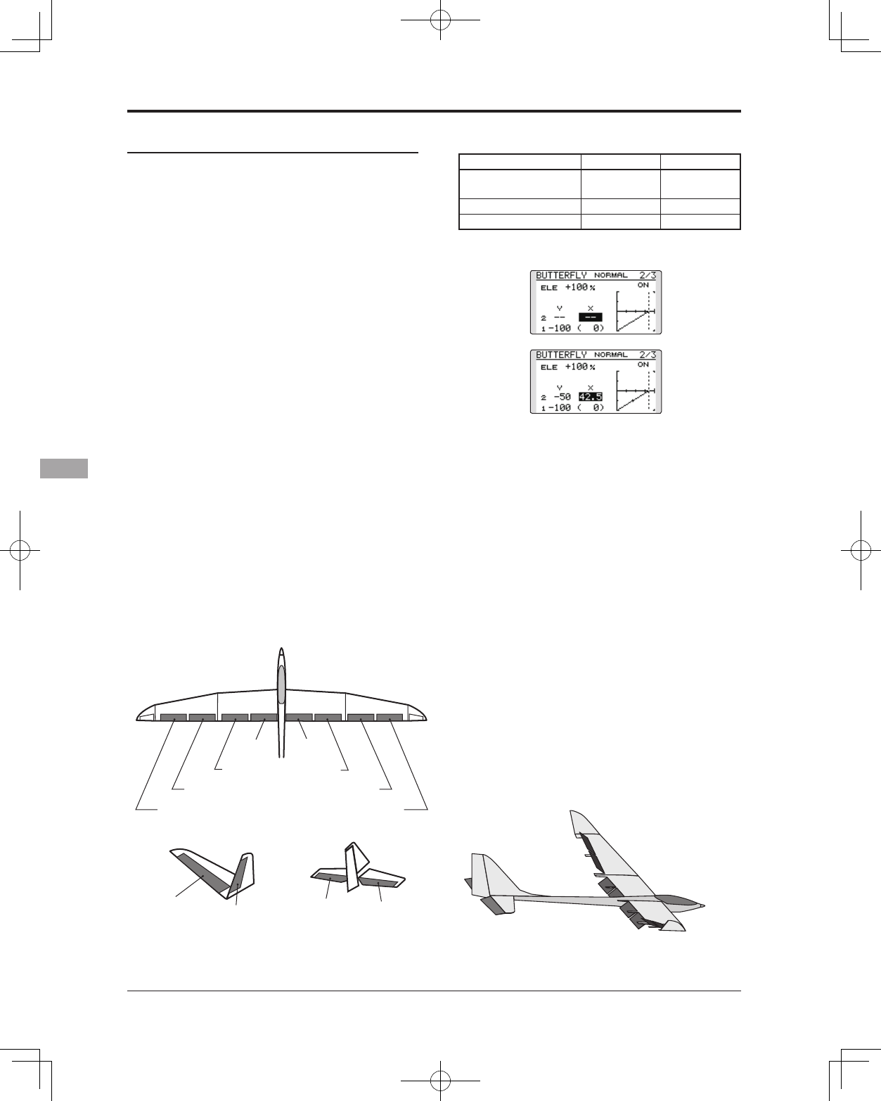
132 <Model Menu (Airplane/Glider Functions)>
Setting method
●Activate the function
Move the cursor to the [ACT] item and touch
the RTN button to switch to the data input
mode. Select the ACT mode by scrolling the
touch sensor.
*The display blinks.
Touch the RTN button to activate the
function and return to the cursor mode. (ON
is displayed.)
When setting a switch, move the cursor to
the [SW] item and touch the RTN button to
call the selection screen. Select the switch
and set its ON direction. (Always ON at "--"
setting)
*For a description of the switch selection method, see the
description at the back of this manual.
●Rate adjustment
Move the cursor to the aileron, flap or
elevator rate item and touch the RTN button
to switch to the data input mode. Adjust the
rate independently by scrolling the touch
sensor.
Initial value: 0%
Adjustment range: -200~+200% (Elevator:
-120~+120%)
*When the RTN button is touched for one second, the rate is
reset to the initial value.)
Touch the RTN button to end the adjustment
and return to the cursor mode.
● Elevator compensation curve adjustment
Output (Y) Position (X)
Offset point Fixed (0) Fixed (offset
position)
2- Intermediate point Settable Settable
1- End point Settable Fixed
* The range where mixing does not work close to the neutral
position of the elevator stick can be adjusted. (Glider only)
*When offset is set, the curve is initialized.
●Reference point adjustment
Move the cursor to the [OFFSET] item and
hold the airbrake stick to the desired position
and then touch the RTN button for one
second to set the butterfly operational
reference point.
Initial value: 0% (upper side)
Adjustment range: 0~100%
●Servo speed setting
Move the cursor to the aileron, flap or
elevator speed item and touch the RTN
button to switch to the data input mode.
Adjust the rate by scrolling the touch sensor.
Initial value: 0
Adjustment range: 0~27 (maximum delay)
*When the RTN button is touched for one second, the rate is
reset to the initial value.)
Touch the RTN button to activate the
function and return to the cursor mode.
AIL 3
(Chip Aileron) AIL 4
(Chip Aileron)
AIL1
(Main Aileron) AIL 2
(Main Aileron)
FLP 2
(Camber Flap)
FLP 1
(Camber Flap)
ELEVATOR ELEVATOR 2
V-TAIL
ELEVATOR ELEVATOR 2
AILVATOR
FLP 3
(Brake Flap) FLP 4
(Brake Flap)
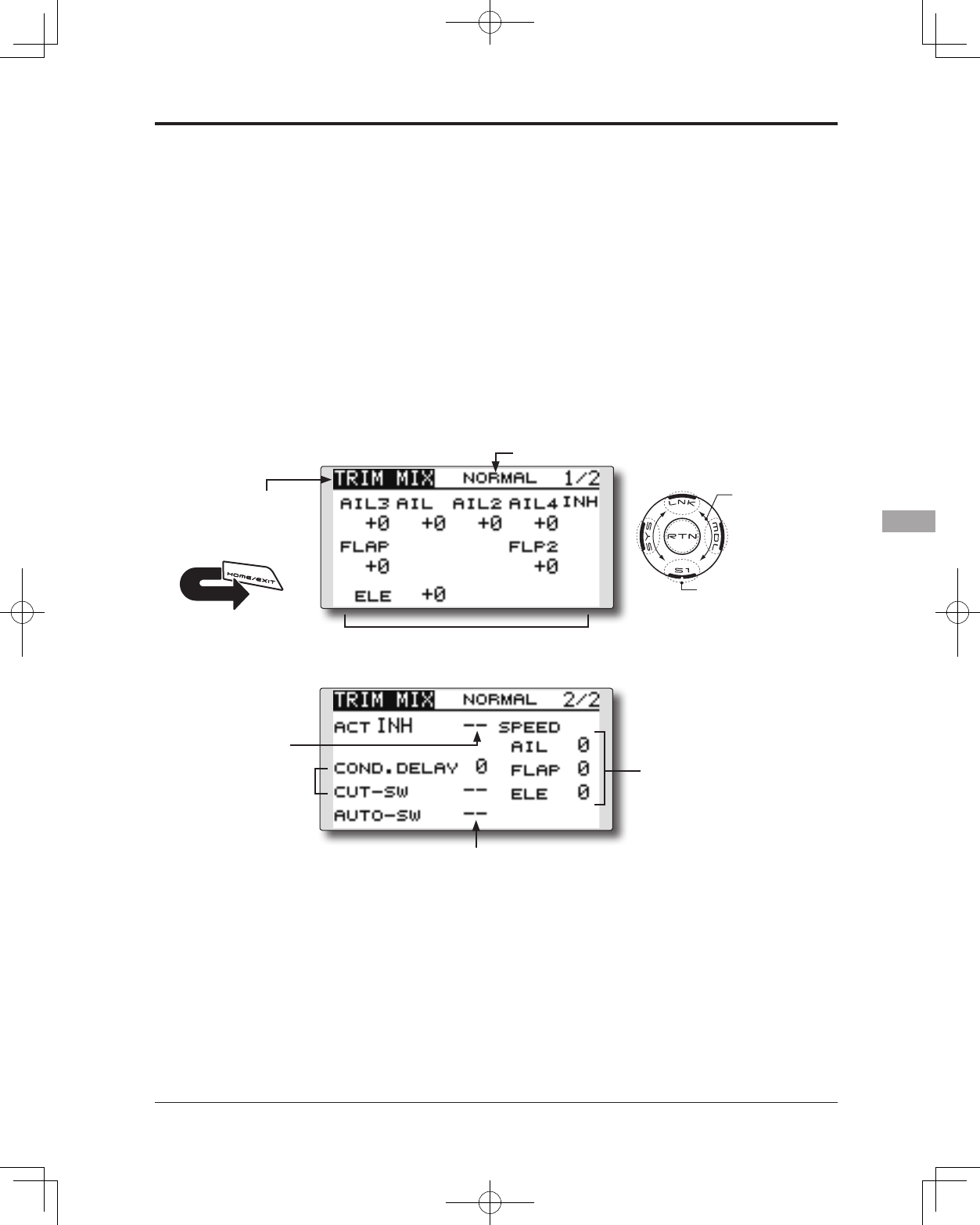
133
<Model Menu (Airplane/Glider Functions)>
● Select the function name
and return to the Model
menu by touching the
RTN button. Or the
HOME/EXIT button is
pushed.
<SensorTouch™>
RETURN
TRIM MIX [Corresponding model type]: Glider, 2 ailerons or more
This function adjusts the trim offset rates of the
ailerons, elevators, and aps (camber aps, brake
aps) according to the ight status.
As an example this function can be set up for
launching, with speed aps and ailerons drooped,
and a slight amount of up elevator, and can be
used for high speed ying, with both ailerons and
speed flaps reflexed slightly, and a bit of down
elevator.
To prevent sudden trim changes when switching
ight conditions, a delay can be set to provide a
● Select [TRIM MIX] at the Model menu
and access the setup screen shown
below by touching the RTN button.
*The display screen is an example. The actual
screen depends on the model type.
Scrolling
● Moving cursor
● Selecting mode
● Adjusting value
● To next page
smooth transition between the two conditions. It
is also possible to program a cut switch which
will turn off the delay.
Furthermore, you can set the auto switch, which
will link the trim mix to a stick, switch, or dial.
Additionally, the speed of the aileron, elevator,
and ap servos can be adjusted.
(Currently selected condition name)
● Condition delay
setting
● Ailerons, flaps, and
elevators servo speed
setting
●Auto switch selection
● Ailerons, flaps, and
elevators offset rate
●Switch
selection
134 <Model Menu (Airplane/Glider Functions)>
Setting method
●Activate the function
Move the cursor to the [ACT] item and touch
the RTN button to switch to the data input
mode. Select the ACT mode by scrolling the
touch sensor.
*The display blinks.
Touch the RTN button to activate the
function and return to the cursor mode. (ON
is displayed.)
When setting a switch, move the cursor to
the switch item and touch the RTN button
to access the selection screen. Select the
switch and set its ON direction. (Always ON
at "--" setting)
*For a description of the switch selection method, see the
description at the back of this manual.
●Trim offset rate adjustment
Move the cursor to the aileron, flap or
elevator rate item and touch the RTN button
to switch to the data input mode. Adjust the
rate independently by scrolling the touch
sensor.
Initial value: 0%
Adjustment range: -250~+250%
*When the RTN button is touched for one second, the rate is
reset to the initial value.)
Touch the RTN button to end the adjustment
and return to the cursor mode.
●Condition delay setting
Move the cursor to the [COND.DELAY] item
and touch the RTN button to switch to the
data input mode. Adjust the condition delay
by scrolling the touch sensor.
Initial value: 0
Adjustment range: 0~27
*When the RTN button is touched for one second, the servo
operation position is reset to the initial value.)
Touch the RTN button to end the adjustment
and return to the cursor mode.
When setting a cut switch, move the cursor
to the [CUT-SW] item and touch the RTN
button to access the selection screen. Select
the switch and set its ON direction. (Always
ON at "--" setting)
*For a description of the switch selection method, see the
description at the back of this manual.
●Servo speed setting
Move the cursor to the aileron, flap or
elevator speed item and touch the RTN
button to switch to the data input mode.
Adjust the rate by scrolling the touch sensor.
Initial value: 0
Adjustment range: 0~27 (maximum delay)
*When the RTN button is touched for one second, the rate is
reset to the initial value.)
Touch the RTN button to activate the
function and return to the cursor mode.
●Auto switch selection
When selecting an auto switch, move the
cursor to the [AUTO-SW] item and touch the
RTN button to access the selection screen.
Select the switch and set its ON direction.
(Always ON at "--" setting)
*For a description of the switch selection method, see the
description at the back of this manual.
AIL 3
(Chip Aileron) AIL 4
(Chip Aileron)
AIL1
(Main Aileron) AIL 2
(Main Aileron)
FLP 2
(Camber Flap)
FLP 1
(Camber Flap)
ELEVATOR ELEVATOR 2
V-TAIL
ELEVATOR ELEVATOR 2
AILVATOR
FLP 3
(Brake Flap) FLP 4
(Brake Flap)
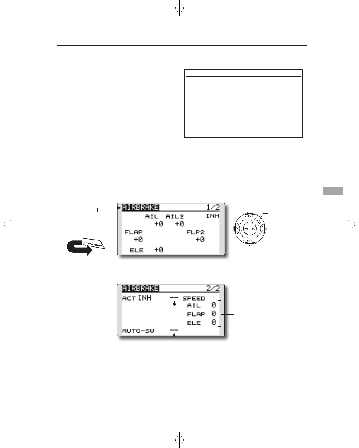
135
<Model Menu (Airplane/Glider Functions)>
● Select the function name
and return to the Model
menu by touching the
RTN button. Or the
HOME/EXIT button is
pushed.
<SensorTouch™>
RETURN
AIRBRAKE [Corresponding model type]: Airplane, 2 ailerons or more
This function is used to increase the aircraft's
drag and is useful for landing or diving, etc.
The preset elevators and flaps (camber flap,
brake flap) offset amount can be activated by a
switch.
The offset amount of the aileron, elevator, and
flap servos can be adjusted as needed. Also the
speed of the aileron, elevator, and ap servos can
be adjusted. If the Auto Mode is activated, this
will link the Airbrake to a stick, switch, or dial. A
separate stick switch or dial can also be set as the
ON/OFF switch.
Setting example for F3A and other aperon specications
(When 2 ailerons model type selected)
Offset rate:
AIL: [-35~-45%], AIL2: [-35~-45%], ELE: [+5~7%]
Note: The input numerics are examples. Adjust the travel to
match the aircraft.
Mode setting:
ACT: [ON]
Switch: [SW-C]
AUTO-SW: [--]
● Select [AIRBRAKE] at the Model menu and access
the setup screen shown below by touching the
RTN button.
*The display screen is an example. The
actual screen depends on the model type.
Scrolling
● Moving cursor
● Selecting mode
● Adjusting value
● To next page
● Ailerons, flaps, and
elevators servo speed
setting
●Auto switch selection
● Ailerons, flaps, and
elevators offset rate
●Switch
selection
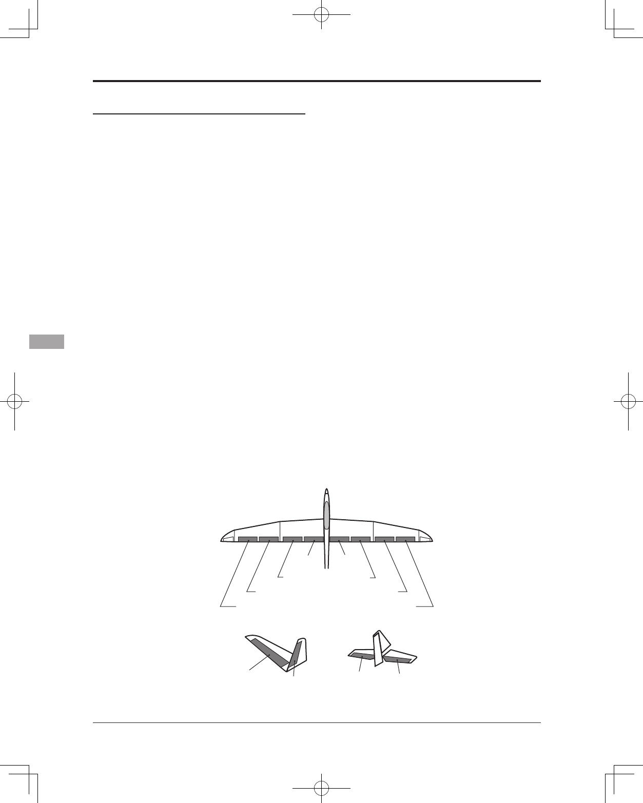
136 <Model Menu (Airplane/Glider Functions)>
Setting method
●Activate the function
Move the cursor to the [ACT] item and touch
the RTN button to switch to the data input
mode. Select the ACT mode by scrolling the
touch sensor.
*The display blinks.
Touch the RTN button to activate the
function and return to the cursor mode. (ON
is displayed.)
When setting a switch, move the cursor to
the switch item and touch the RTN button
to access the selection screen. Select the
switch and set its ON direction. (Always ON
at "--" setting)
*For a description of the switch selection method, see the
description at the back of this manual.
●Offset rate adjustment
Move the cursor to the aileron, flap or
elevator rate item and touch the RTN button
to switch to the data input mode. Adjust the
rate independently by scrolling the touch
sensor.
Initial value: 0%
Adjustment range: -250~+250%
*When the RTN button is touched for one second, the rate is
reset to the initial value.)
Touch the RTN button to end the adjustment
and return to the cursor mode.
●Servo speed setting
Move the cursor to the aileron, flap or
elevator speed item and touch the RTN
button to switch to the data input mode.
Adjust the rate by scrolling the touch sensor.
Initial value: 0
Adjustment range: 0~27 (maximum delay)
*When the RTN button is touched for one second, the rate is
reset to the initial value.)
Touch the RTN button to return to the cursor
mode.
●Auto switch selection
When setting a auto switch, move the cursor
to the [AUTO-SW] item and touch the RTN
button to access the selection screen. Select
the switch and set its ON direction. (Always
ON at "--" setting)
*For a description of the switch selection method, see the
description at the back of this manual.
AIL 3
(Chip Aileron) AIL 4
(Chip Aileron)
AIL1
(Main Aileron) AIL 2
(Main Aileron)
FLP 2
(Camber Flap)
FLP 1
(Camber Flap)
ELEVATOR ELEVATOR 2
V-TAIL
ELEVATOR ELEVATOR 2
AILVATOR
FLP 3
(Brake Flap) FLP 4
(Brake Flap)
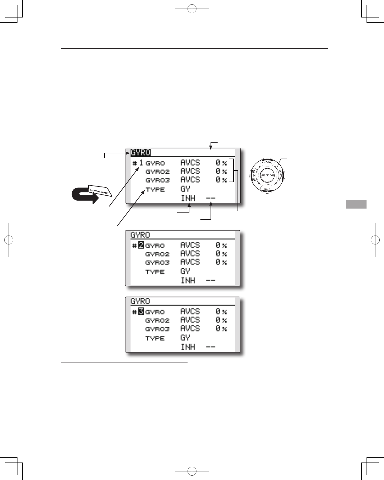
137
<Model Menu (Airplane/Glider Functions)>
● Select the function name
and return to the Model
menu by touching the
RTN button. Or the
HOME/EXIT button is
pushed.
<SensorTouch™>
RETURN
GYRO [Corresponding model type]: Airplane/glider, general
This function is used when a GYA Series gyro
is used to stabilize the aircraft's attitude. The
sensitivity and operation mode (Normal mode/
AVCS mode) can be changed via a switch.
● Three rates (Rate 1/Rate 2/Rate 3) can be
switched.
● Up to 3 axes (Gyro/Gyro 2/Gyro 3) can be
simultaneously controlled.
Note: This setting does not assign a sensitivity
channel. To do so, use the Linkage menu
prior to assigning the sensitivity channel
(Gyro/Gyro2/Gyro3), be sure to select an
unused channel.
Set the [Control] and [Trim] settings other than
Function to [--].
● The operation mode (AVCS/NOR)
and sensitivity of the three axis
Gyro/Gyro2/Gyro3 can be set.
● Select [GYRO] at the Model menu and
access the setup screen shown below
by touching the RTN button.
Scrolling
● Moving cursor
● Selecting mode
● Adjusting value
● To next page
(Active rate # display)
● Gyro type
selection
● ACT/INH
● Switch selection
● Rate1-3 setup
screen selection
[Rate 1 setup screen]
[Rate 2 setup screen]
[Rate 3 setup screen]
Setting method
*Prior to using the Function menu in the Linkage menu to
assign the sensitivity channel (Gyro/Gyro2/Gyro3) select an
unused channel.
Set [Control] and [Trim] other than function to [--].
●Rate1-3 setup screen selection
Move the cursor to the setup screen selection
item and touch the RTN button to switch
to the data input mode. Select the setup
screen # by scrolling the touch sensor.
Touch the RTN button to change the setup
screen and return to the cursor mode.
●Activate the function
Move the cursor to the [INH] item and touch
the RTN button to switch to the data input
mode. Select the ACT mode by scrolling the
touch sensor.
*The display blinks.
Touch the RTN button to activate the
function and return to the cursor mode.
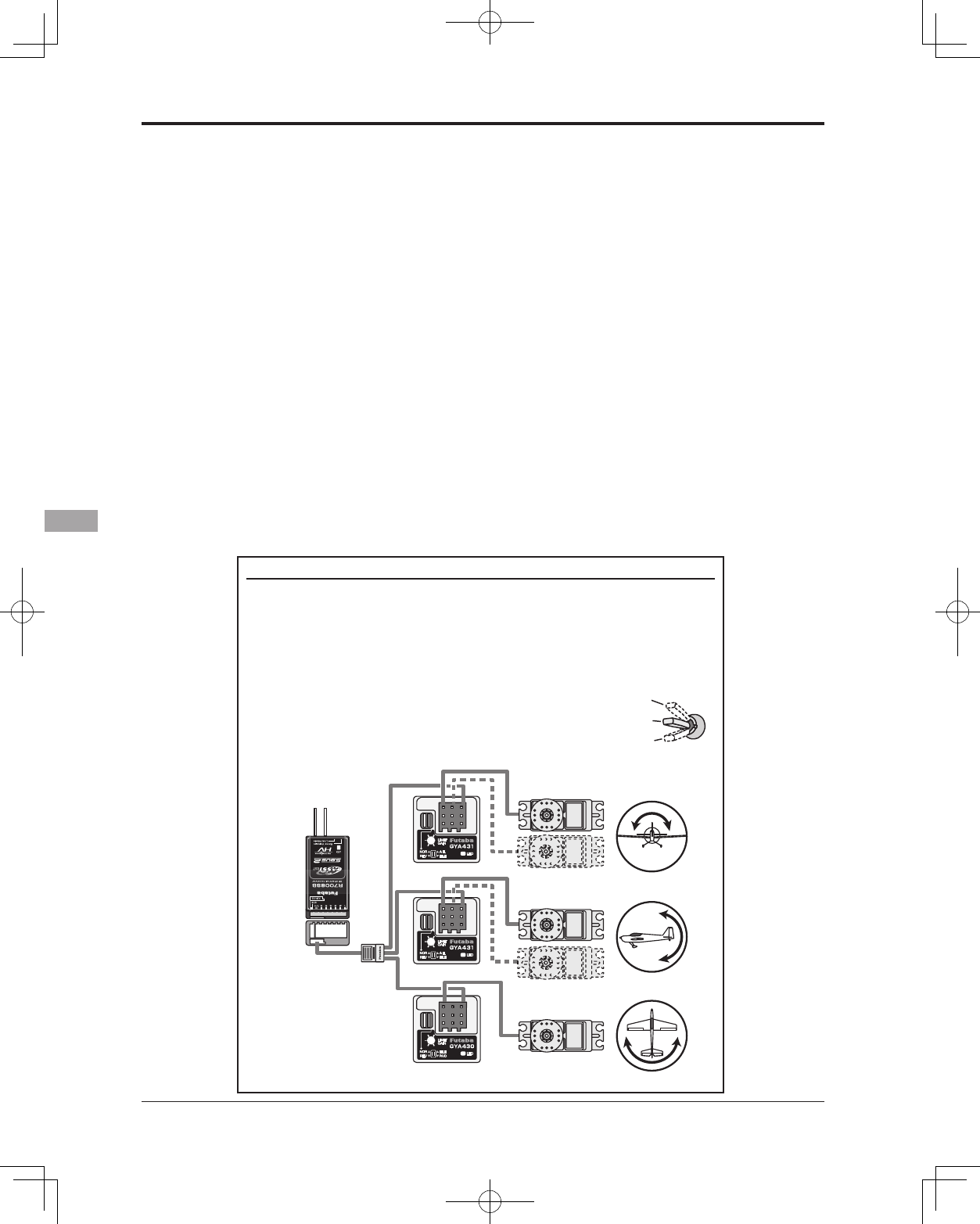
138 <Model Menu (Airplane/Glider Functions)>
When setting a rate selection switch, move
the cursor to the switch item and touch the
RTN button to access the selection screen.
Select the switch and set its ON direction.
(Always ON at "--" setting)
*For a description of the switch selection method, see the
description at the back of this manual.
●Gyro type selection
Move the cursor to the gyro type selection
item and touch the RTN button to switch to
the data input mode. Select the gyro type
by scrolling the touch sensor.
[GY]: When a Futaba GYA gyro is used
[NORM]: When using something other than
Futaba GYA gyro is used.
Touch the RTN button to change the gyro
type and return to the cursor mode.
*When a Futaba GYA gyro is used and [GY] type is selected,
the sensitivity set value is directly read in both the AVCS
and NORM modes.
●Operation mode selection (GYA gyro)
Move the cursor to the operation mode
selection item and touch the RTN button
to switch to the data input mode. Select
the operation mode by scrolling the touch
sensor.
[AVCS]: AVCS mode
[NORM]: Normal mode
Touch the RTN button to change the
operation mode and return to the cursor
mode.
●Sensitivity setting
Move the cursor to the sensitivity icon and
touch the RTN button to switch to the data
input mode.
Adjust the sensitivity by scrolling the touch
sensor.
Initial value: 0%
Adjustment range: 0~100%
*When the RTN button is touched for one second, the
sensitivity is reset to the initial value.)
Touch the RTN button to return to the cursor
mode.
(Example) Setting three axis using a GYA430 and GYA431 (2)
● Wing type: Aileron 2 servos mounted fuselage selected
● Set Gyro 1 (GYA431AIL): CH5, Gyro 2 (GYA431ELE): CH7, Gyro 3 (GYA430RUD): CH8 at
the Function menu of the Linkage menu.
● Rate 1 [OFF][GY][SE][NORM][60%][NORM][60%][NORM][60%]
Rate 2 [INH]
Rate 3 [OFF][GY][SE][AVCS][60%][AVCS][60%][AVCS][60%]
*Set so that Rate 1 is turned on at the back position of switch E and Rate 3 is turned ON at the front
position. Since switch E is turned OFF at the center, Rate 2 remains [INH].
R7008SB
Rudder servo
Elevator servo
GYA430
GYA431
GYA431
Aileron servo
S.BUS/S.BUS2 port
*When a S.BUS port is used
R7008SB CH Mode is set to
ModeB [D].
GAIN 0%
AVCS
NORMAL
When AVCS is used we
recommend that the
sensitivity CH be set to
the 3-position.
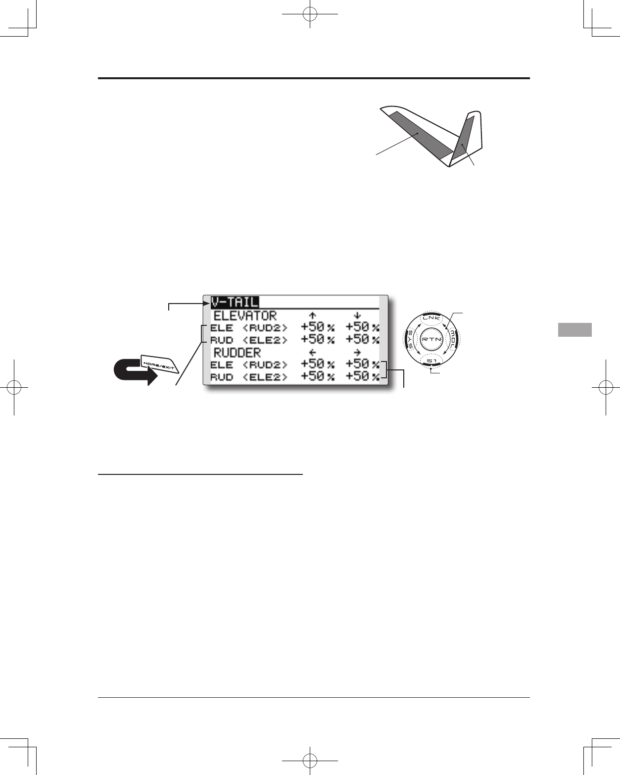
139
<Model Menu (Airplane/Glider Functions)>
● Select the function name
and return to the Model
menu by touching the
RTN button. Or the
HOME/EXIT button is
pushed.
<SensorTouch™>
RETURN
ELEVATOR
(RUDDER 2) RUDDER
(ELEVATOR 2)
V-TAIL [Corresponding model type]: Airplane/glider, V-tail
This function enables adjustments for left and
right rudder angle changes during elevator and
rudder operation of a V-tail airplane.
V-tail is when two servos are used together to
control rudder movement as elevators. In addition
to each elevator side moving up and down together,
each side moves in opposite directions when moving
as rudders. On a V-tail, this is also known as a
Ruddervator, as they serve the same purpose.
(Rudder function)
Left and right travel
adjustment of rudder
operation
(Elevator function)
Up and down travel adjustment of
elevator operation
● Select [V-TAIL] at the Model menu and
access the setup screen shown below
by touching the RTN button.
Scrolling
● Moving cursor
● Selecting mode
● Adjusting value
● To next page
Setting method
● Travel adjustment
Move the cursor to the item you want to
adjust and touch the RTN button to switch to
the data input mode.
Adjust the rate by scrolling the touch sensor.
Initial value: +50%
Adjustment range: -120~+120%
*When the RTN button is touched for one second, the rate is
reset to the initial value.)
Touch the RTN button to return to the cursor
mode.
*If the mixing direction is reversed, adjustments can be made
by changing the mixing rate polarity (+ or -).
*If a large value of travel is specified, when the sticks are
moved at the same time, the controls may bind or run out of
travel. Decrease the travel until no binding occurs.
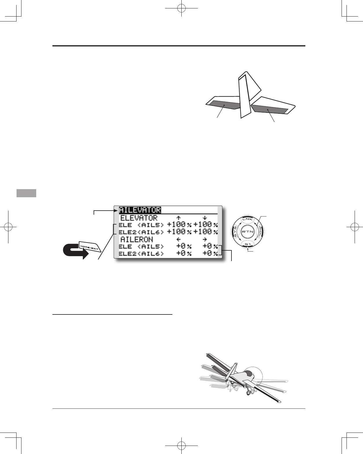
140 <Model Menu (Airplane/Glider Functions)>
● Select the function name
and return to the Model
menu by touching the
RTN button. Or the
HOME/EXIT button is
pushed.
<SensorTouch™>
RETURN
ELEVATOR ELEVATOR 2
(AILERON 5) (AILERON 6)
AILEVATOR [Corresponding model type]: Airplane/glider, Ailevator
(Effective only when 2 servos used at the elevators)
This function improves the performance of the roll
axis by operating the elevators as ailerons.
Ailevator is where each elevator in a standard
(conventional) or v-tail moves independently, like
ailerons on a wing. In addition to each elevator side
moving up and down together, each side moves in
opposite directions when moving as an Ailevator. On
a V-tail, this is also known as a Ruddervator, as they
can serve the same purpose. Typically, both Ailevator
and ailerons are coupled together to maximize roll
performance, especially on larger wingspan planes.
Note: Select Ailevator as the Model Type at the Model
Type screen. This changes the output channel. Check
the Function menu.
(Aileron function)
● When the elevators are used
as ailerons, aileron travel of
the left and right elevators
can be adjusted.
(Elevator function)
● The up and down rate of both
elevators when the elevator stick
is moved can be individually
adjusted.
● Select [AILEVATOR] at the Model menu
and access the setup screen shown
below by touching the RTN button.
Scrolling
● Moving cursor
● Selecting mode
● Adjusting value
● To next page
Setting method
● Travel adjustment
Move the cursor to the item you want to
adjust and touch the RTN button to switch to
the data input mode.
Adjust the rate by scrolling the touch sensor.
Initial value: ELE: +100%, AIL: 0%
Adjustment range: -120~+120%
*When the RTN button is touched for one second, the rate is
reset to the initial value.)
Touch the RTN button to return to the cursor
mode.
*If the mixing direction is reversed, adjustments can be made
by changing the mixing rate polarity (+ or -).
*If a large value of travel is specified, when the sticks are
moved at the same time, the controls may bind or run out of
travel. Decrease the travel until no binding occurs.
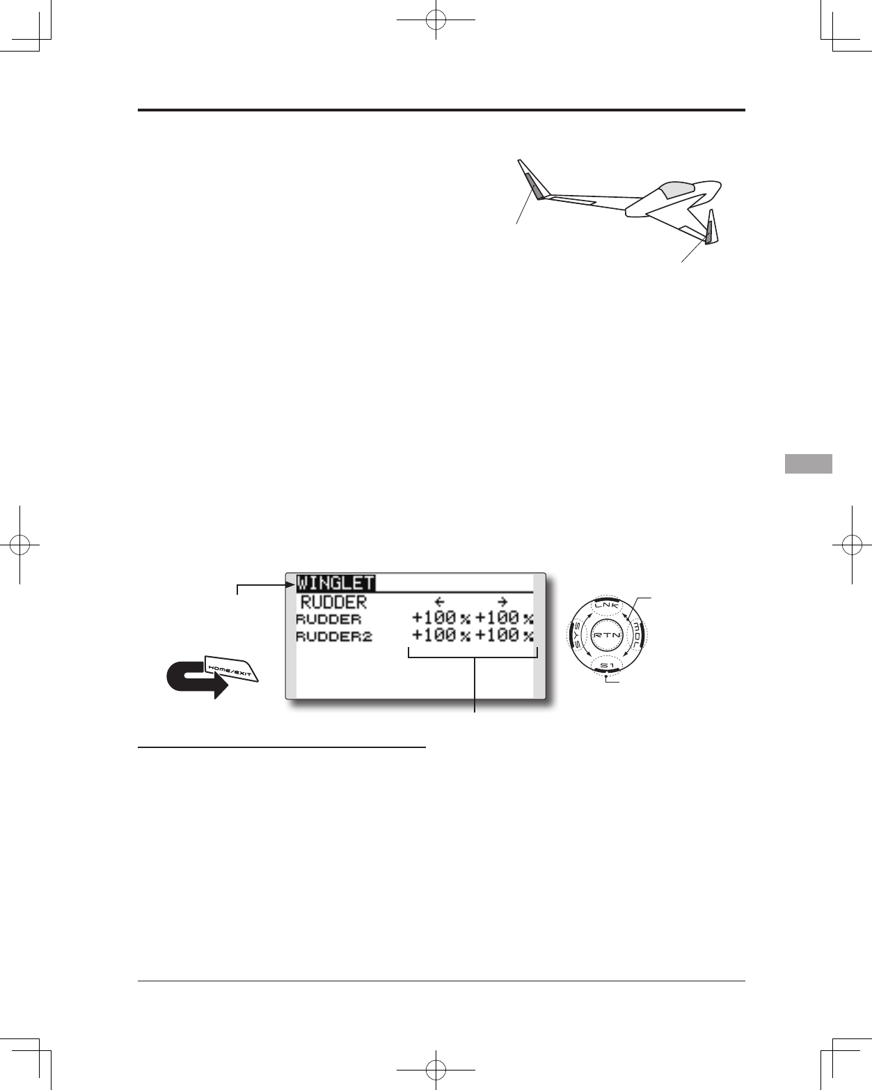
141
<Model Menu (Airplane/Glider Functions)>
● Select the function name
and return to the Model
menu by touching the
RTN button. Or the
HOME/EXIT button is
pushed.
<SensorTouch™>
RETURN
RUDDER 1
Winglet
at Flying wing
( )
RUDDER 2
Winglet
at Flying wing
( )
WINGLET [Corresponding model type]: Airplane/glider, Flying wing only
This function adjusts the left and right rudder
angles of airplanes with winglets.
Winglets are used to improve the efficiency of
aircraft by lowering the lift-induced drag caused by
wingtip vortices. The winglet is a vertical or angled
extension located at the tip of each wing.
Winglets work by increasing the effective aspect
ratio wing without adding greatly to the structural
stress and hence necessary weight of its structure
- an extension of wing span would also permit
lowering of induced drag, though it would cause
parasitic drag and would require boosting the
strength of the wing and hence its weight. There
would come a point at which no overall useful
gains would be made. A winglet helps to solve this
by effectively increasing the aspect ratio without
adding to the span of the wing.
(Rudder 1/2)
● The travel during rudder stick operation
can be individually adjusted.
● Select [WINGLET] at the Model menu
and access the setup screen shown
below by touching the RTN button.
Scrolling
● Moving cursor
● Selecting mode
● Adjusting value
● To next page
Setting method
● Travel adjustment
Move the cursor to the item you want to
adjust and touch the RTN button to switch to
the data input mode.
Adjust the rate by scrolling the touch sensor.
Initial value: +100%
Adjustment range: -120~+120%
*When the RTN button is touched for one second, the rate is
reset to the initial value.)
Touch the RTN button to return to the cursor
mode.
*If the mixing direction is reversed, change the mixing rate
polarity (+ or -).
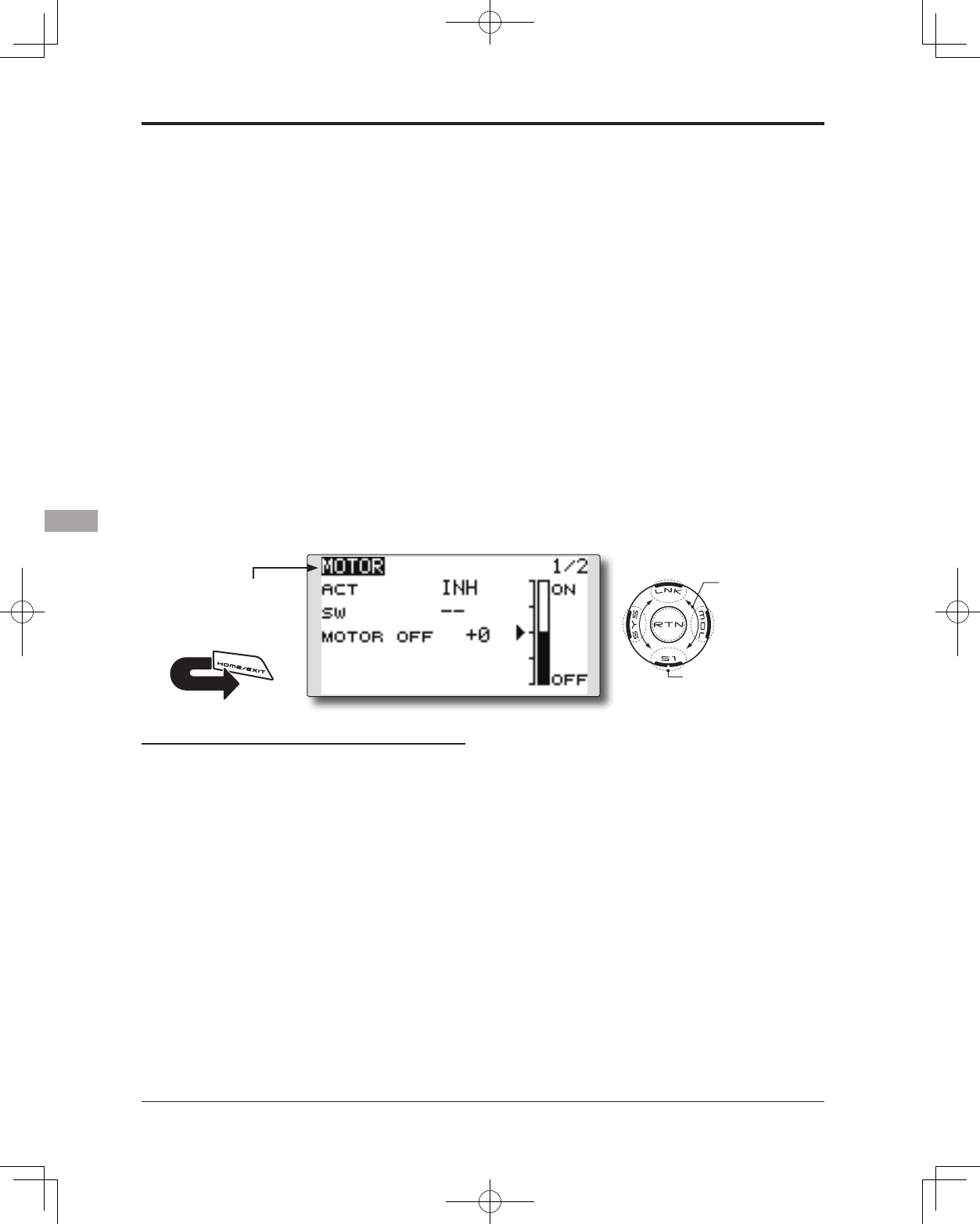
142 <Model Menu (Airplane/Glider Functions)>
● Select the function name
and return to the Model
menu by touching the
RTN button. Or the
HOME/EXIT button is
pushed.
<SensorTouch™>
RETURN
MOTOR [Corresponding model type]: Airplane/glider, general
This function lets you set the speed when the
motor of an F5B or other EP glider is started via
a switch. The operation speed can be set for two
ranges, slow speed flight and high speed flight
(Speed 1/Speed 2). This function can also be
operated as a safety function by programming it to
a switch.
● The In side and Out side operating speeds can
be adjusted independently in 2 ranges (Speed 1/
Speed 2).
● The boundary between the 2 ranges can be set.
(From Speed 1 to Speed 2)
● The operational speed can only be activated at
the initial operation. However, operation can be
repeated by setting the switch to OFF before the
operation is nished. When you want to reset one
time operation, set the ACT/INH item to [INH] and
then reset it to [ON].
● The motor channel is controlled by SW-G. (Glider:
Initial setting) When changing the switch or stick
which controls the motor, rst change Function of
the Linkage menu.
● If the Model Type selected is Airplane, the MOTOR
function is changed from INH to ON and it is not
assigned to another channel, the changes from
the throttle channel to the motor channel are
enabled.
Note: Initial setting does not assign a motor
channel according to the model type. Prior to
assigning the motor channel, nd an unused
channel. Then, use the Function menu of the
Linkage menu.
Set [Control] to the switch you want to use
and [Trim] to [--].
Note: When using this function, always check
the initial operation with the propeller
removed.
● Select [MOTOR] at the Model menu
and access the setup screen shown
below by touching the RTN button.
Scrolling
● Moving cursor
● Selecting mode
● Adjusting value
● To next page
Setting method
● Activate the function
When using this function, move the cursor to
the [ACT/INH] item and touch the RTN button
to switch to the data input mode. Select the
[ACT] by scrolling the touch sensor and touch
the RTN button.
When selecting the ON/OFF switch, move the
cursor to the switch item and touch the RTN
button to access the selection screen. Select
the switch and set its ON direction. (Always
ON at "--" setting)
*For a description of the switch selection method, see the
description at the back of this manual.
● Motor off position setting
Move the cursor to the [MOTOR OFF] item
and touch the RTN button for one second
when the motor function switch (SG, etc.) is
in the motor OFF position you want to set. The
direction of the motor switch is memorized.
The screen graph display OFF direction also
changes.
Note:
● First decide the motor OFF direction, and then
set the speed. When you want to reset the
motor OFF direction, also reset the speed.
● We recommend that Motor OFF be set in
combination with F/S.
● Set the basic operation direction with the
Reverse function to match the ESC used.
● Always set the Motor OFF position.
143
<Model Menu (Airplane/Glider Functions)>
Setting method
● Activate the motor speed function
When using motor speed function, move the
cursor to the [INH] item and touch the RTN
button to switch to the data input mode.
Select the [ACT] by scrolling the touch sensor
and touch the RTN button.
● Sifting the boundary between the 2 ranges
Move the cursor to the [SPEED 1>2] item and
touch the RTN button to switch to the data
input mode.
Adjust the boundary position by scrolling the
touch sensor.
Initial value: 0%
Adjustment range: -100~+100%
*When the RTN button is touched for one second, the rate is
reset to the initial value.)
Touch the RTN button to return to the cursor
mode.
● Operation speed adjustment
Move the cursor to the [IN] (on to off) or [OUT]
(off to on) item and touch the RTN button to
switch to the data input mode.
Adjust the operation speed you want to set
by scrolling the touch sensor.
Initial value: 0
Adjustment range: 0~27
*When the RTN button is touched for one second, the rate is
reset to the initial value.)
Touch the RTN button to return to the cursor
mode.
● Set/Reset the one time operation
Move the cursor to the [ONE TIME] item and
touch the RTN button to switch to the data
input mode.
Select the [ACT] by scrolling the touch sensor
and touch the RTN button to set the one time
operation.
* When you want to reset one time operation, set the ACT/
INH item to [INH] and then reset it to [ON].
● Motor function switch
current position
●Start switch function
When active, the "START SW" allows the
motor's state to change from OFF to ON. The
motor is ON when the main SW and "START
SW" are turned ON simultaneously. The motor
changes to OFF only when the main SW is
turned off. If "START SW" is turned OFF but the
main SW is still ON, the motor remains ON.
[START SW function example]
When the throttle (motor) stick is assigned as the "START SW",
and the low throttle position of the throttle curve is adjusted, the
motor starts operating with the initial stick movement. The motor
will not cease functionality even if the stick position is returned to
it's lowest setting.
●Trim effect / invalid setting in motor OFF
If one of the trim levers is assigned to the
Motor function, it is possible to turn the
motor off with the trim lever. To maintain
compatibility after updating the T14SG/S,
the trim setting is adjusted to the on position.
However, it is suggested to return it to the off
position accordingly in the programming of
the transmitter.
*Data Reset will return the trim setting to the off position.
●Screen at the time of the motor OFF setting
When the MOTOR OFF setting is highlighted,
you will note the presence of the small cursor
that indicates the MOTOR OFF position. To
adjust this MOTOR OFF position, use the
throttle stick to move the cursor accordingly.
When satisfied with this position, press and
hold the RTN button on the transmitter.
*The larger cursor is used to indicate the output of the motor
channel. This cursor reects any throttle curves and motor
mixing which may be active.
●Throttle curve button
When "CURVE" button is chosen, a throttle
curve screen opens.
*When a throttle function is assigned to either channel, the
"CURVE" button is not displayed because a throttle curve
does not function as a motor curve.
● ON/OFF direction
144 <Model Menu (Airplane/Glider Functions)>
● Select the function name
and return to the Model
menu by touching the
RTN button. Or the
HOME/EXIT button is
pushed.
<SensorTouch™>
RETURN
RUD to ELE [Corresponding model type]: Airplane, general
This function is used when you want to mix
elevator operation with rudder operation. It is used
to correct undesirable tendencies when rudder is
applied in rolling maneuvers such as, knife edge
ight.
● Mixing during flight can be turned ON/OFF by
setting a switch. (Always ON at [--] setting)
● Link mixing can be set: Links this mix to other mixes.
● Select [RUD to ELE] at the Model
menu and access the setup screen
shown below by touching the RTN
button.
Scrolling
● Moving cursor
● Selecting mode
● Adjusting value
● To next page
Setting method
●Activate the function
Move the cursor to the [ACT] item and touch
the RTN button to switch to the data input
mode. Select the ACT mode by scrolling the
touch sensor.
*The display blinks.
Touch the RTN button to activate the
function and return to the cursor mode. (ON
is displayed.)
When selecting a switch, move the cursor to
the [SW] item and touch the RTN button to
call the selection screen. Select the switch
and set its ON direction. (Always ON at "--"
setting)
*For a description of the switch selection method, see the
description at the back of this manual.
●5-point curve setting (airplane)
[Curve rate setting]
1. Move the cursor to the curve rate setting
item (left side) you want to adjust and touch
the RTN button to switch to the data input
mode.
Adjust the rate by scrolling the touch sensor.
Adjustment range: -100%~+100%
*When the RTN button is touched for one second, the rate is
reset to the initial value.)
Touch the RTN button to end the adjustment
and return to the cursor mode.
2. Repeat this procedure for each point.
[Moving curve point]
1. Move the cursor to the curve point setting
item you want to adjust and touch the RTN
button to switch to the data input mode.
Adjust the curve point by scrolling the touch
sensor.
Adjustment range: Up to 2.5% in front of the
adjoining point
*When the RTN button is touched for one second, the curve
position is reset to the initial value.)
Touch the RTN button to end the adjustment
and return to the cursor mode.
2. Repeat this procedure for each point.
[Deleting/returning curve point]
Move the cursor to the curve point setting
item you want to delete/return and touch
the RTN button for one second.
●Link mode setting
When selecting the link mixing, move the
cursor to the [LINK] item and touch the RTN
button to switch to the data input mode.
Select the ON mode by scrolling the touch
sensor.
*The display blinks.
Touch the RTN button to set the link mode
and return to the cursor mode.
145
<Model Menu (Airplane/Glider Functions)>
● Select the function name
and return to the Model
menu by touching the
RTN button. Or the
HOME/EXIT button is
pushed.
<SensorTouch™>
RETURN
SNAP ROLL [Corresponding model type]: Airplane, general
This function selects the switch and rate
adjustment of ailerons, elevators, and rudder when
a snap roll is performed.
● Four snap roll directions can be set. (Right/up,
right/down, left/up, left/down)
● Operation mode: When [Master] mode is selected,
the Snap Roll function is turned ON/OFF by the
master switch. It is possible to set the direction
switch was switched to the direction in which you
want to snap roll. When [Single] mode is selected,
the snap roll in each direction can be executed
by means of independent switches and positions.
● A safety switch can be set to prevent the
inadvertent activation of the snap roll. For
example, the landing gear is lowered, even if
the switch is turned on accidentally the snap roll
would not be executed. The snap roll switch is
activated only when the safety switch is OFF.
(Example) Setting example for F3A
● Mode: [Master]
● Safety SW: [SG] (Safety measure)
● Master SW: [SH] (Main switch for executing
snap roll)
● Direction switches:
*The snap roll up side left and right and down side left and right
direction switches are selected here.
Right/Up: OFF [SD]
Right/Down: OFF [SD]
Left/Up: OFF [SA]
Left/Down: OFF [SA]
● Master/single mode
selection
● Select [SNAP ROLL] at the Model menu
and access the setup screen shown
below by touching the RTN button.
Scrolling
● Moving cursor
● Selecting mode
● Adjusting value
● To next page
● Direction switches
146 <Model Menu (Airplane/Glider Functions)>
Setting method
●Master/single mode selection
Move the cursor to the [MODE] item and
touch the RTN button to switch to the data
input mode. Select the master or single
mode by scrolling the touch sensor.
*The display blinks.
[MASTER]: Master mode
[SINGLE]: Single mode
Touch the RTN button to select the mode
and return to the cursor mode.
When setting a master switch, move the
cursor to the [MASTER-SW] item and touch
the RTN button to access the selection
screen. Select the switch and set its ON
direction.
*For a description of the switch selection method, see the
description at the back of this manual.
When setting a safety switch, move the
cursor to the [SAFETY-SW] item and touch the
RTN button to access the selection screen.
Select the switch and set its ON direction.
●Direction switch selection
Move the cursor to the direction switch item
and touch the RTN button to access the
selection screen. Select the switch and set its
ON direction.
*For a description of the switch selection method, see the
description at the back of this manual.
●Rate adjustment
Move the cursor to the aileron, elevator or
rudder item for each direction and touch the
RTN button to switch to the data input mode.
Adjust the rate independently by scrolling
the touch sensor.
Initial value: (Dependent upon the snap roll
direction)
Adjustment range: -150~+150%
*When the RTN button is touched for one second, the rate is
reset to the initial value.)
Touch the RTN button to end the adjustment
and return to the cursor mode.
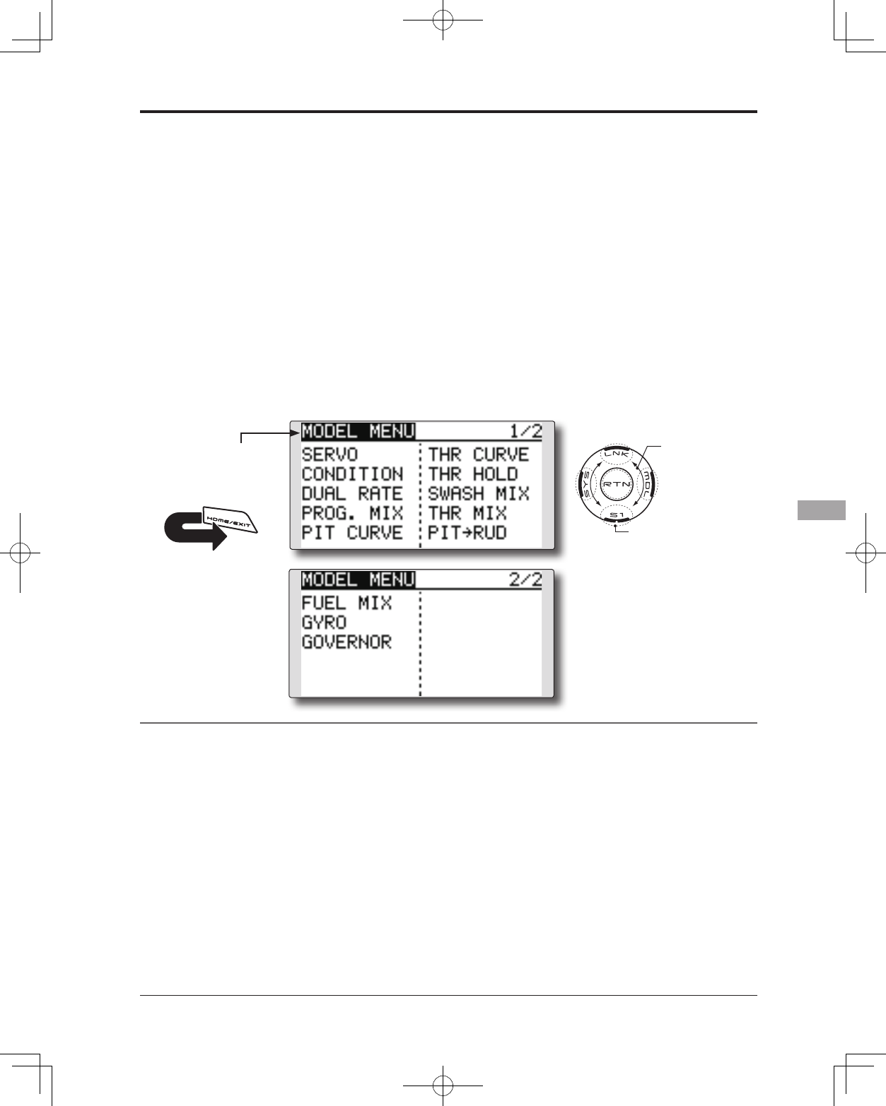
147
<Functions of Model Menu (Helicopter Functions)>
●Selectthefunctionname
andreturntotheModel
menubytouchingthe
RTNbutton. Orthe
HOME/EXIT buttonis
pushed.
<SensorTouch™>
RETURN
MODEL MENU (HELICOPTER)
This section contains information on the
commands that apply to helicopters only. For
instructions on Airplanes and Sailplanes, refer to
the sections pertaining to those aircraft.
Use the Model Type function in the Linkage
Menu to select the swash type matched to the
respective aircraft.
Also, activate/deactivate flight conditions
according to your model. To do so, access at the
Condition Select screen prior to adjusting the
model's parameters. (Up to ve conditions can be
used)
The Dual Rate function and other functions
common to all model types have already been
described elsewhere in this manual. Please refer to
these respective sections for information on how to
do so.
Model Menu functions (helicopter) list
PIT CURVE: Adjusts pitch settings in different ight conditions
THR CURVE: Throttle curve and hovering trim adjustment in different ight conditions
THR HOLD: Moves the throttle to idle during autorotation
SWASH MIX: Compensates control response in different ight conditions
THROTTLE MIX: Compensates for power loss when cyclic applied
PIT to NEEDLE: Adjusts pitch response in different ight conditions
PIT to RUD: Compensates torque changes from pitch angle inputs
GYRO: Used to switch gyro sensitivity
GOVERNOR: Used to switch RPM of the helicopter’s head
●AccesstheModelmenushownbelowby
touchingtheRTNbuttontwiceatthehome
screen,etc.
Scrolling
●Movingcursor
●Tonextpage
●Selectthefunctionyou
wanttosetandaccess
thesetupscreenby
touchingtheRTNbutton.
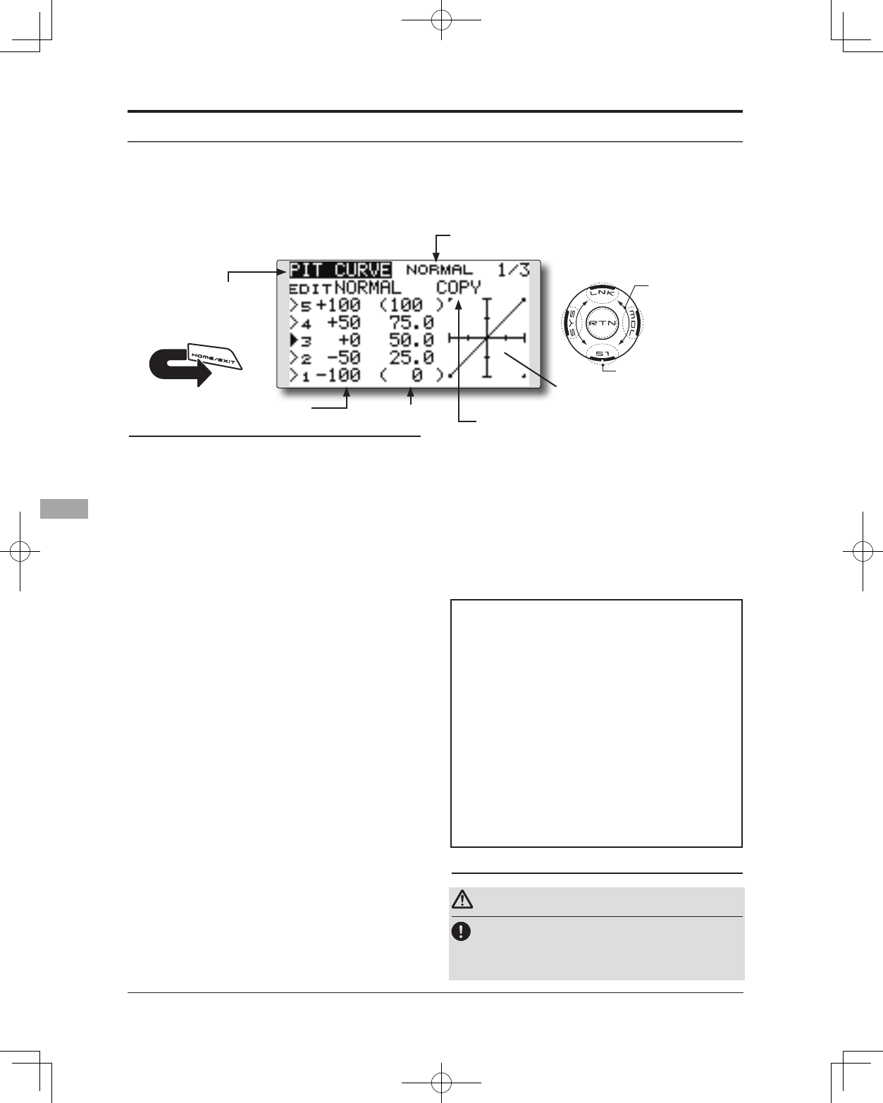
148 <Functions of Model Menu (Helicopter Functions)>
●Selectthefunctionname
andreturntotheModel
menubytouchingthe
RTNbutton. Orthe
HOME/EXIT buttonis
pushed.
<SensorTouch™>
RETURN
PIT CURVE/PIT TRIM
Pitch Curve
This function adjusts the pitch operation curve
for each flight condition to optmize the model's
performance in relationship to the throttle stick position.
*A simple curve can be created by reducing the number of
input points to two or three, and then entering the specied
value at the corresponding points.
Normal curve adjustment
*For normal curve, create a basic pitch curve centered
about hovering. Use this function together with the THR
Curve (Normal) function and adjust the curve so that up/
down control is best at a constant engine speed.
Idle up curve adjustment
*For the high side pitch curve, set the maximum pitch
so that it does not overload the engine. For the low side
pitch curve, create curves matched to loop, roll, 3D, and
other purposes and use the idle up curves according to the
performance.
Throttle hold curve adjustment
*The throttle hold curve is used when executing auto
rotations.
Operation precautions
Warning
When actually starting the engine and flying,
always set the idle up condition switch to OFF
and start the engine at idle.
●Select[PITCURVE]attheModelmenuandaccess
thesetupscreenshownbelowbytouchingthe
RTNbutton.
●Pitchcurvecopy
Scrolling
●Movingcursor
●Selectingmode
●Adjustingvalue
●Tonextpage
(Currently selected condition name)
1.Movethecursortothecurvepointsetting
itemyouwanttodelete/returnandtouch
theRTNbuttonforonesecond.
●Pitch curve copy function
MovethecursortoCOPYandtouchtheRTN
buttontoswitchtothedatainputmode.
Selectthecopydestinationconditionby
scrollingthetouchsensorandtouchtheRTN
button.Selectthe[YES]andtouchtheRTN
button.
●curverate ●curvepoint
Setting method
●5-point curve setting
[Curveratesetting]
1.Movethecursortothecurveratesetting
itemyouwanttoadjustandtouchtheRTN
buttontoswitchtothedatainputmode.
Adjusttheratebyscrollingthetouchsensor.
Initialvalue:P1:-100%,P2:-50%,P3:0%,P4:
+50%,P5:+100%
Adjustmentrange:-100%~+100%
*When the RTN button is touched for one second, the rate is
reset to the initial value.
TouchtheRTNbuttontoendtheadjustment
andreturntothecursormode.
2.Repeatthisprocedureforeachpointas
desired.
[Movingcurvepoint]
1.Movethecursortothecurvepointsetting
itemyouwanttoadjustandtouchtheRTN
buttontoswitchtothedatainputmode.
Adjustthecurvepointbyscrollingthetouch
sensor.
Initialvalue:P1:(0%),P2:25%,P3:50%,P4:
75%,P5:(100%)
Adjustmentrange:Upto2.5%infrontofthe
adjoiningpoint
*When the RTN button is touched for one second, the curve
position is reset to the initial value.)
TouchtheRTNbuttontoendtheadjustment
andreturntothecursormode.
2.Repeatthisprocedureforeachpointas
desired.
[Deleting/returningcurvepoint]
*The graph display includes the pitch
trim operation.
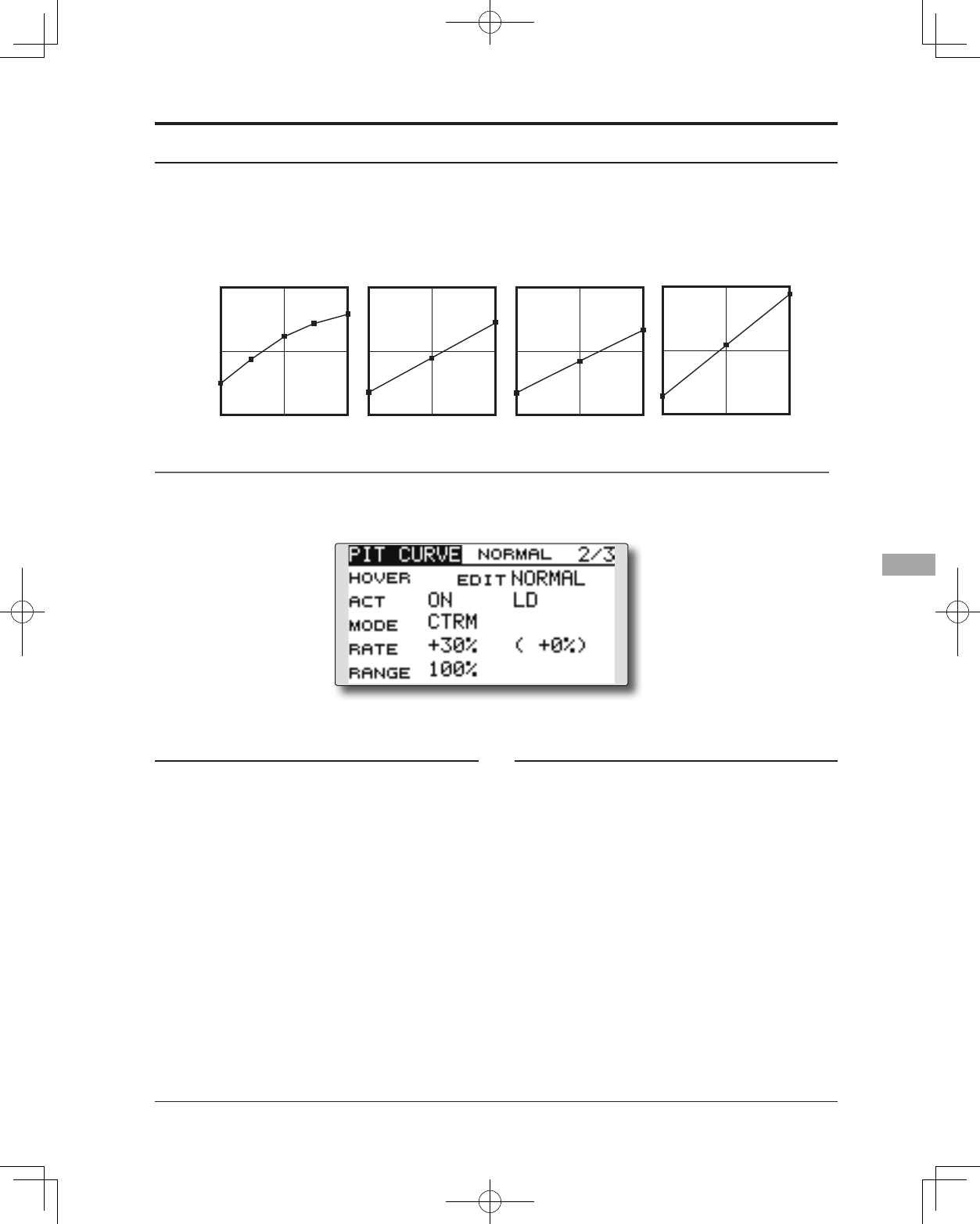
149
<Functions of Model Menu (Helicopter Functions)>
Normal Curve Idle-up 1 Curve Idle-up 2 Curve Hold Curve
●Pitch Curve (Example)
The screens shown below are curves created by
entering the pitch rate at low, center, and high side (3
points or 5 points) at each condition.
When actually creating a curve, input the rate
specied by the model (or the reference value).
Curve setting examples
Pitch Trim (Hovering pitch, high pitch, low pitch)
[Hoveringpitchtrimsetting]
Hovering pitch trim
The Hovering Pitch trim function trims the pitch
near the hovering point. Normally, it is used with
the hovering condition. The hovering pitch can be
ne tuned for changes in rotor speed accompanying
changes in temperature, humidity, and other ight
conditions. Adjust the hovering pitch so that
rotor speed is constant. This function can be used
together with the Hovering Throttle Trim function
for more precise operation.
Setting method
●SetthefunctiontoACT[ON].(initialsetting)
●Selecttheadjustmentknob.
Selectionexample:LD(initialsetting)
●Thetrimoperationmode(Mode:CTRM/
NORM)canbeselected.
CTRM mode:Maximumamountofchange
nearcenterbycentertrimoperation
(recommended)
NORM mode:Normaltrim(parallel
movementtrim)operation.Theadvantage
ofusingthismodeisthatthehoveringpitch
canbeadjustedwithoutchangingthe
curve.
●Thetrimratecanbeadjustedandthe
operationdirectioncanbechanged.
●Trimadjustmentrange(Range)setting
Whenthisvalueismadesmall,trimcanonly
beusednearthecenter.
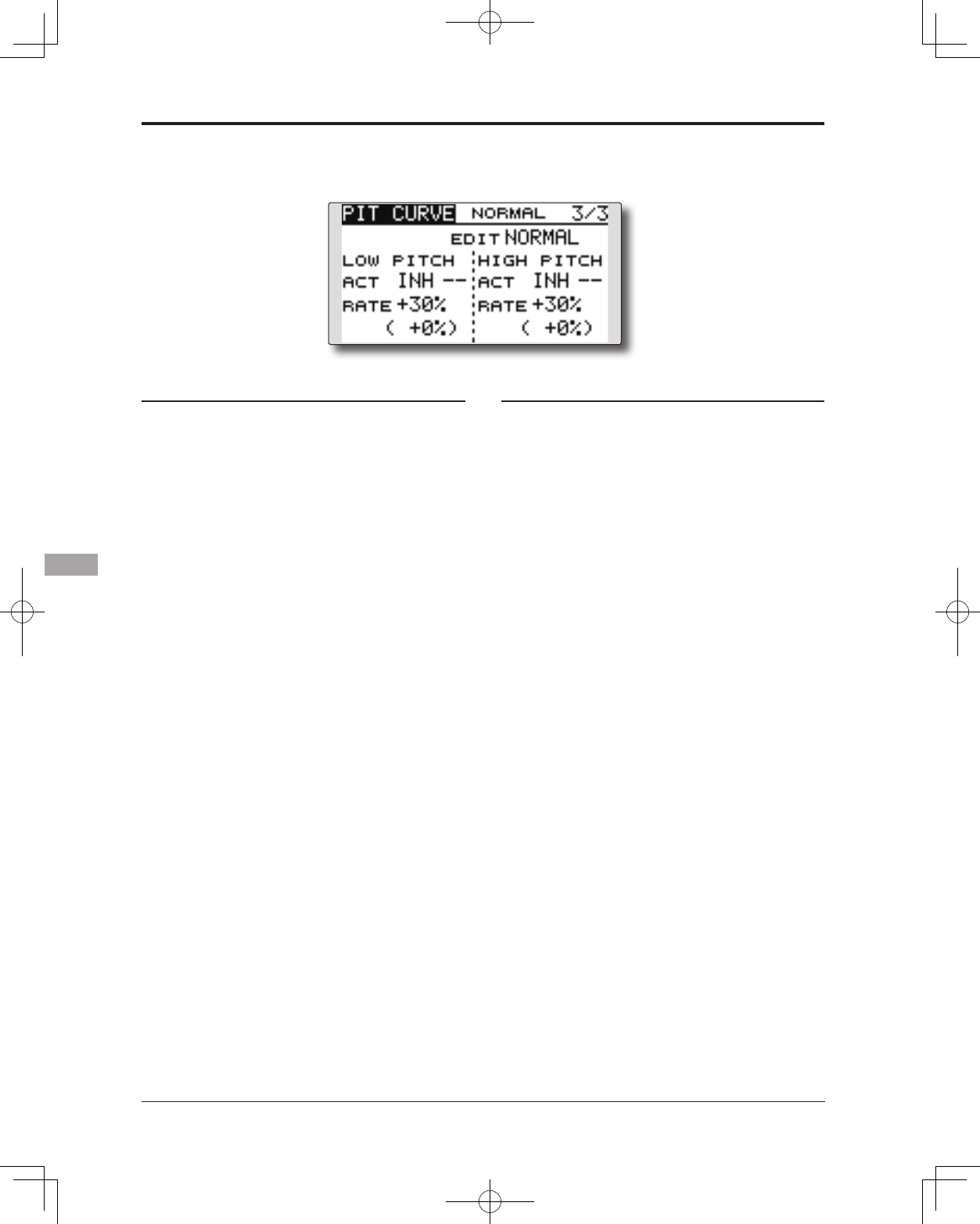
150 <Functions of Model Menu (Helicopter Functions)>
[Low/Highpitchtrimsetting]
High Pitch/Low Pitch Trim
High Pitch/Low Pitch Trim is the pitch servo
high side and low side trim function.
Setting method
●SetthefunctiontoACT(ON).
●Selecttheadjustmentknobs.
Selectionexample:LS(highside),RS(low
side)
●Thetrimratecanbeadjustedandthe
operationdirectioncanbechanged.
●Trimactsashighsideorlowsidetrimwiththe
centerasthestandard.
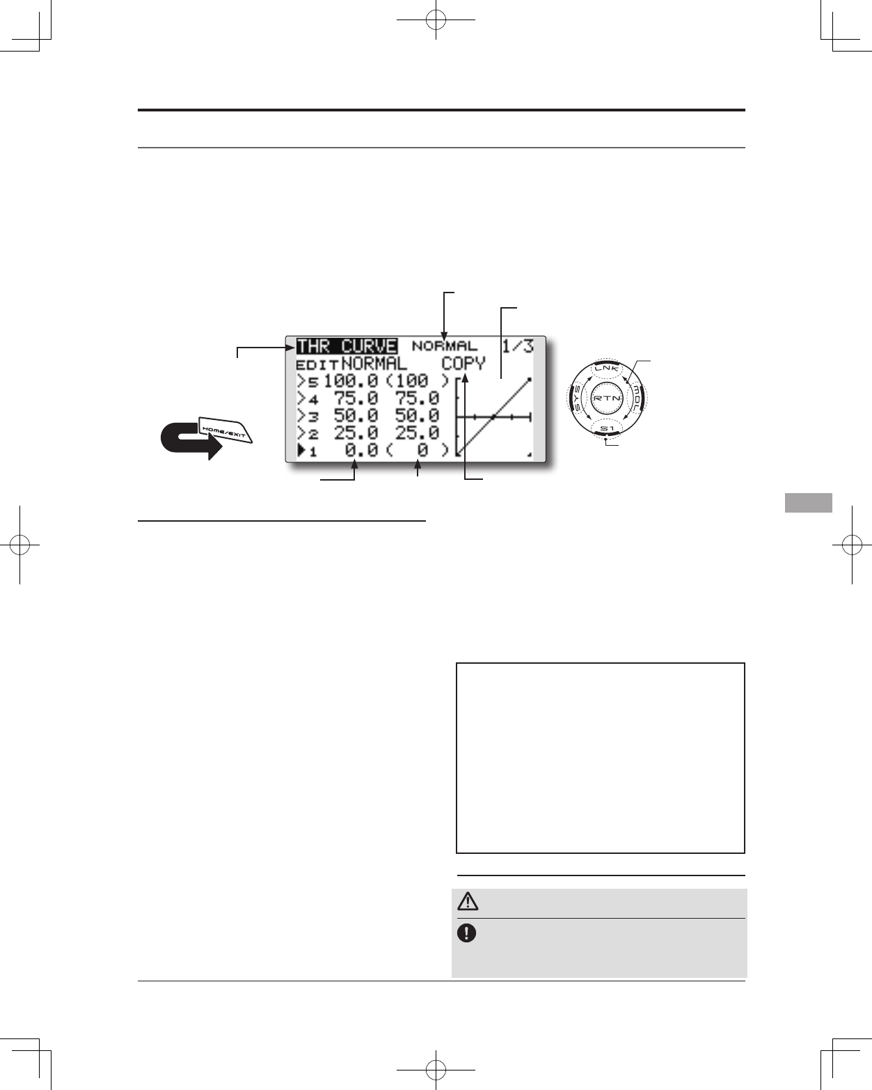
151
<Functions of Model Menu (Helicopter Functions)>
●Selectthefunctionname
andreturntotheModel
menubytouchingthe
RTNbutton. Orthe
HOME/EXIT buttonis
pushed.
<SensorTouch™>
RETURN
THR CURVE/THROTTLE HOVER TRIM
Throttle Curve
Throttle curve function adjusts the throttle
operation curve for each condition to optimize the
engine speed to throttle stick movement.
The Throttle Hover function trims the throttle
near the hovering point. Normally, use it with
hovering conditions. Changes in rotor speed
accompanying changes in the temperature,
humidity, and other flight conditions can be
trimmed. Adjust the throttle so that rotor rotation is
most stable. More precise trimming is also possible
by using this function along with the Hover Pitch
function.
●Select[THRCURVE]attheModelmenuand
accessthesetupscreenshownbelowby
touchingtheRTNbutton.
*The graph display includes the throttle
hover trim operation.
Scrolling
●Movingcursor
●Selectingmode
●Adjustingvalue
●Tonextpage
(Currently selected condition name)
●Throttlecurvecopy
●curverate ●curvepoint
Normal curve adjustment
*Normal curve creates a basic curve centered around
hovering. Use it along with the normal pitch curve and
adjust so that up/down control results in a constant engine
speed.
Idle up curve adjustment
*Set a idle up curve that maintains a constant speed at all
times, even during operation which reduces the pitch
performed in ight. Create a curve matched to loop, roll,
3D, or other purposes and the idle up curve according to
the performance.
Operation precautions
Warning
When actually starting the engine and flying,
always set the idle up condition switch to OFF
and start the engine at the idle.
[Deleting/returningcurvepoint]
1.Movethecursortothecurvepointsetting
itemyouwanttodelete/returnandtouch
theRTNbuttonforonesecond.
●Throttle curve copy function
MovetheCOPYitemandtouchtheRTN
buttontoswitchtothedatainputmode.
Selectthecopydestinationconditionby
scrollingthetouchsensorandtouchtheRTN
button.Selectthe[YES]andtouchtheRTN
button.
Setting method
●5-point curve setting
[Curveratesetting]
1.Movethecursortothecurveratesetting
itemyouwanttoadjustandtouchtheRTN
buttontoswitchtothedatainputmode.
Adjusttheratebyscrollingthetouchsensor.
Initialvalue:P1:0%,P2:25%,P3:50%,P4:75%,
P5:100%
Adjustmentrange:0%~100%
*When the RTN button is touched for one second, the rate is
reset to the initial value.)
TouchtheRTNbuttontoendtheadjustment
andreturntothecursormode.
2.Repeatthisprocedureforeachpointas
desired.
[Movingcurvepoint]
1.Movethecursortothecurvepointsetting
itemyouwanttoadjustandtouchtheRTN
buttontoswitchtothedatainputmode.
Adjustthecurvepointbyscrollingthetouch
sensor.
Initialvalue:P1:(0%),P2:25%,P3:50%,P4:
75%,P5:(100%)
Adjustmentrange:Upto2.5%infrontofthe
adjoiningpoint
*When the RTN button is touched for one second, the curve
position is reset to the initial value.)
TouchtheRTNbuttontoendtheadjustment
andreturntothecursormode.
2.
Repeatthisprocedureforeachpointasdesired.
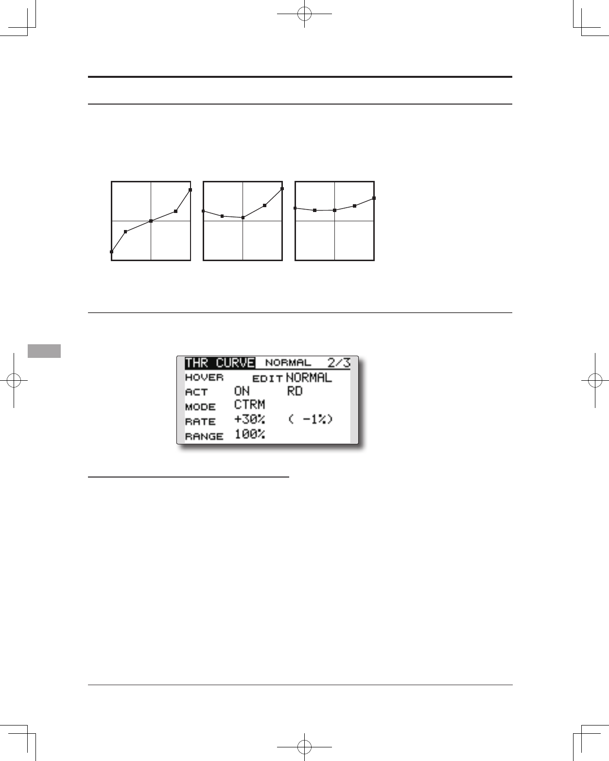
152 <Functions of Model Menu (Helicopter Functions)>
Normal Curve Idle-up 1 Curve Idle-up 2 Curve
●Throttle Curve (Example)
The curves shown below are created by inputting
the data of the 5 points 0% (low side), 25%,
50% (center), 75%, 100% (high) side for each
condition. When actually creating a curve, enter the
parameters specied per the model (or the reference
value).
Curve setting examples
Throttle Hover trim
Setting method
●SetthefunctiontoACT([ON]).(initialsetting)
●Selecttheadjustmentknob.
Selectionexample:RD(initialsetting)
●Thetrimoperationmode(Mode:CTRM/
NORM)canbeselected.
CTRM mode:Maximumrateofchange
nearcenterbycentertrimoperation
(recommended)
NORM mode: Normaltrim(horizontal
movementtrim)operation.
●Thetrimratecanbeadjustedandthe
operationdirectioncanbeset.
●Trimadjustmentrange(Range)setting
Withsmallervalues,thetrimisonlyactive
nearthecenter.
[Throttlehovertrimsetting]
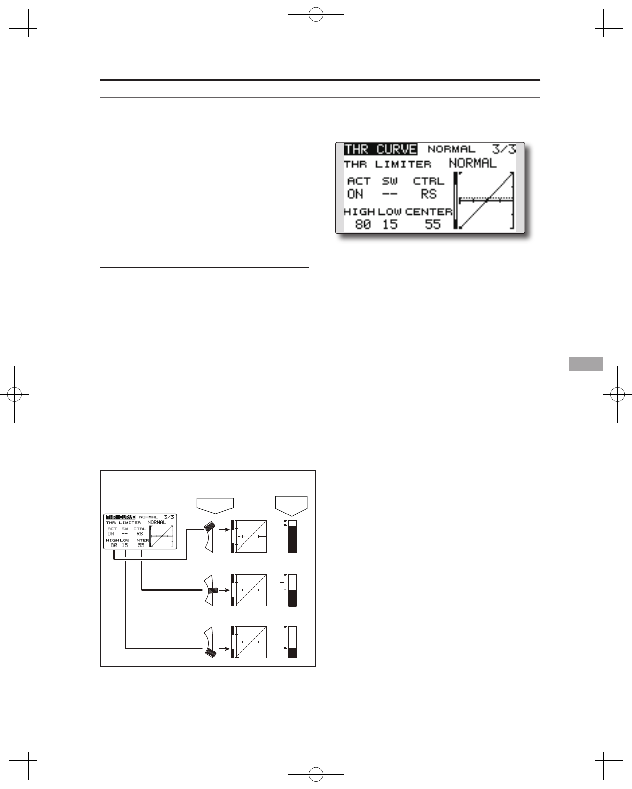
153
<Functions of Model Menu (Helicopter Functions)>
Throttle limiter function
Setting method
*Set at the 3rd page of the throttle curve screen.
•Activate the function.
1.SelectACTandtouchtheRTNbutton.
2.SwitchthedisplaytoACTbyscrollingthe
touchsensor.
*Thedisplayblinks.
INH:Inhibit
ACT:Activate
3.EntertheselectionbytouchingtheRTN
button.
•ON/OFF switch setting
1.SelectSWandtouchtheRTNbutton.
2.TheH/WSETscreenisdisplayed.Selectthe
hardwareandtouchtheRTNbutton.
This function limits the high range of the throttle
movement by any slider or trimmer.
*Control which adjusts the limit point during ight can be set.
•High side operating range setting
1.SelectHIGHandtouchtheRTNbutton.
2.Adjustthehighsideoperatingrangeby
scrollingthetouchsensor.
*A gauge is displayed at the left side of the graph.
3.TouchtheRTNbuttontoswitchtothecursor
mode.
•Low side operating range setting
1.SelectLOWandtouchtheRTNbutton.
2.Adjustthelowsideoperatingrangeby
scrollingthetouchsensor.
*A gauge is displayed at the left side of the graph.
3.TouchtheRTNbuttontoswitchtothecursor
mode.
•Limiter operating range adjustment control
setting
1.SelectCTRLandtouchtheRTNbutton.
2.TheH/WSETscreenisdisplayed.Selectthe
hardwareandtouchtheRTNbutton.
*The throttle limiter operating position is indicated by a
dotted line on the graph.
*When limiter operating range adjustment control is NULL,
the throttle limiter function is not performed.
•Changing the control center position
1.SelectCENTERandtouchtheRTNbuttonfor
1second.CENTERchangesfromINHto“rate
display”.
2.WhentheCENTERrateischanged,the
neutralpositionofthehardwaresetatCTRL
canbeadjusted.
*When CENTER is INH, the neutral position becomes the
LOW intermediate value.
*When CENTER is changed from INH to “rate display”, the
CENTER rate is set to the LOW intermediate value.
*The CENTER rate can be set between HIGH and LOW.
[Throttlelimitersetting]
When "CTRL" is set as a "RS" side slider.
The state of full high of a throttle stick.
RSPosition Throttle
Position
Full
RestrictionRestrictionRestriction
Slow
Full
Slow
Full
Slow
In "INH", the halfway
point of "HIGH" and
"LOW".
HIGH
LOW
CENTER
SB
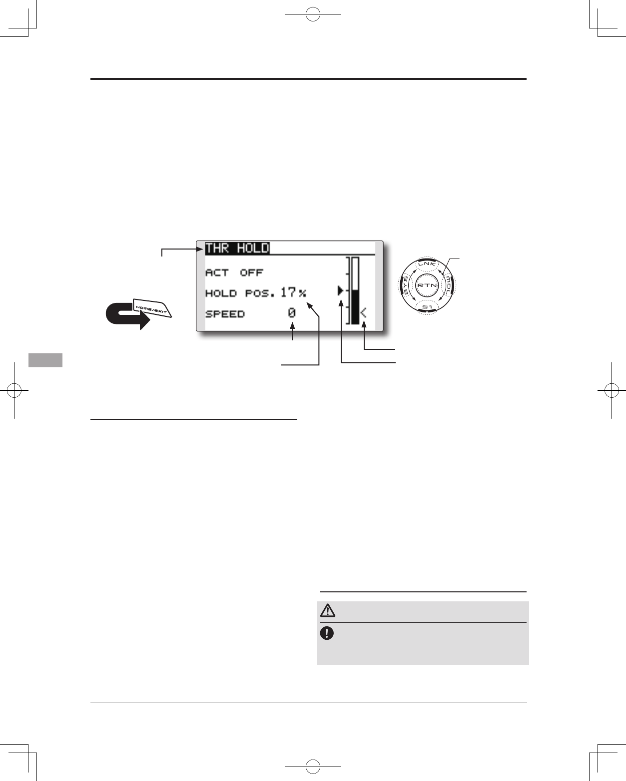
154 <Functions of Model Menu (Helicopter Functions)>
●Selectthefunctionname
andreturntotheModel
menubytouchingthe
RTNbutton. Orthe
HOME/EXIT buttonis
pushed.
<SensorTouch™>
RETURN
THR HOLD
This function sets the throttle cut position for
auto rotation. The throttle servo operating speed
can be adjusted. (Speed)
Note: Initially, this setting does not assign the
throttle hold switch. Prior to adjusting the
parameters for the throttle hold, we suggest
designating a throttle hold switch. To do so,
access the Condition menu within the Model
menu options.
●Servospeed
Setting method
●Hold condition switch selection
UsetheConditionselectmenuoftheModel
menutoassigntheholdconditionswitch.
Selectionexample:SG
●Hold position adjustment
Movethecursortotheholdpositionitem
andtouchtheRTNbuttontoswitchtothe
datainputmode.
Adjusttheratebyscrollingthetouchsensor.
Initialvalue:17%
Adjustmentrange:0%~50%
*Hold position sets the throttle cut position. Adjust it so that
the carburetor is completely closed.
*When the RTN button is touched for one second, the rate is
reset to the initial value.)
TouchtheRTNbuttontoendtheadjustment
andreturntothecursormode.
●Servo speed setting
Movethecursortotheservospeeditemand
touchtheRTNbuttontoswitchtothedata
inputmode.
Adjusttheratebyscrollingthetouchsensor.
Initialvalue:0
Adjustmentrange:0~27(maximumdelay)
*When the RTN button is touched for one second, the rate is
reset to the initial value.)
TouchtheRTNbuttontoreturntothecursor
mode.
●Select[THRHOLD]attheModelmenu
andaccessthesetupscreenshown
belowbytouchingtheRTNbutton.
Scrolling
●Movingcursor
●Selectingmode
●Adjustingvalue
●Holdpositionsetting
●Holdposition
●Currentposition
Operation precautions
Warning
When actually starting the engine and flying,
always set the idle up condition switch to OFF
and start the engine at idle.
155
<Functions of Model Menu (Helicopter Functions)>
●Selectthefunctionname
andreturntotheModel
menubytouchingthe
RTNbutton. Orthe
HOME/EXIT buttonis
pushed.
<SensorTouch™>
RETURN
SWASH MIX
The swash mix function is used to correct the
swash plate in the aileron (roll) direction and
elevator (cyclic pitch) corresponding to each
operation of each condition.
This function allows the independent rate
adjustments for the ailerons, elevator and pitch.
Example of use
●Asanexample,useswashmixingtocorrect
undesirablerolltendencies.
●ForaconditionwhichusesAILtoELE,setthis
functiontoON.
Ifthefrontofthehelicopterraisesduringa
rightroll,whentheRate2sideisinputand
therightaileronisoperated,theelevator
movestothedownside.Tunebyadjusting
theRate.
Forleftroll,adjusttotheRate1side.
Setting method
●Activate the mixing
Whenusingthisfunction,movethecursorto
the[ACT]itemandtouchtheRTNbuttonto
switchtothedatainputmode.
SelecttheACTmodebyscrollingthetouch
sensor.
*The display blinks.
TouchtheRTNbuttontoactivatethemixing
andreturntothecursormode.(ONis
displayed.)
[Switchselection]
When[[--]]isset,theswashmixingfunction
isalwaysactiveandoperatedbymerely
selectingthecondition.
Whensettingan[ON]/[OFF]switch,movethe
cursortothe[SW]itemandtouchtheRTN
buttontoaccesstheselectionscreen.Set
theswitchanditsONposition.
*For a description of the switch selection method, see the
description at the back of this manual.
●Mixing rate adjustment
Movethecursortothemixingrateitemyou
wanttocorrectandtouchtheRTNbutton
toswitchtothedatainputmode.Adjustthe
rateindependentlybyscrollingthetouch
sensor.
Initialvalue:0%
Adjustmentrange:-100~+100%
*When the RTN button is touched for one second, the rate is
reset to the initial value.
TouchtheRTNbuttontoendtheadjustment
andreturntothecursormode.
●Trim mode ON/OFF setting
Whenchangingthetrimmode,movethe
cursortothe[TRIM]itemandtouchtheRTN
buttontoswitchtothedatainputmode.
SelectON/OFFbyscrollingthetouchsensor.
*The display blinks.
TouchtheRTNbuttontochangethetrim
modeON/OFFandreturntothecursor
mode.
*When mixing includes master side trim, select [ON] and
when mixing does not include master trim, select [OFF].
●Select[SWASHMIX]attheModelmenu
andaccessthesetupscreenshown
belowbytouchingtheRTNbutton.
Scrolling
●Movingcursor
●Selectingmode
●Adjustingvalue
●Tonextpage
(Currently selected condition name)
●Conditionselection
156 <Functions of Model Menu (Helicopter Functions)>
●Selectthefunctionname
andreturntotheModel
menubytouchingthe
RTNbutton. Orthe
HOME/EXIT buttonis
pushed.
<SensorTouch™>
RETURN
THROTTLE MIX
This function corrects slowing of engine speed
caused by swash plate operation during aileron
or elevator operation. The method of applying
clockwise or counterclockwise torque when
pirouetting can also be corrected.
Setting example
●AILtoTHRmixingcounteractsthelagin
engineRPM'swhenanaileroninputisgiven
tothehelicopter.Engineover-speeding
canbeadjustedindependentlyforthe
rightaileronandleftaileroninputsutilizing
Rates1and2.
●Select[THROTTLEMIX]attheModelmenuand
accessthesetupscreenshownbelowbytouching
theRTNbutton.
Scrolling
●Movingcursor
●Selectingmode
●Adjustingvalue
●Tonextpage
(Currently selected condition name)
Setting method
●Activate the mixing
Whenusingthisfunction,movethecursorto
the[ACT]itemandtouchtheRTNbuttonto
switchtothedatainputmode.
SelecttheACTmodebyscrollingthetouch
sensor.
*The display blinks.
TouchtheRTNbuttontoactivatethemixing
andreturntothecursormode.(ONis
displayed.)
[Switchselection]
When[[--]]isset,theswashmixingfunction
isalwaysactiveandoperatedbymerely
selectingthecondition.
Whensettingan[ON]/[OFF]switch,movethe
cursortothe[SW]itemandtouchtheRTN
buttontocalltheselectionscreen.Setthe
switchanditsONposition.
*For a description of the switch selection method, see the
description at the back of this manual.
●Mixing rate adjustment
Movethecursortothemixingrateitemyou
wanttocorrectandtouchtheRTNbutton
toswitchtothedatainputmode.Adjustthe
rateindependentlybyscrollingthetouch
sensor.
Initialvalue:0%
Adjustmentrange:-100~+100%
*When the RTN button is touched for one second, the rate is
reset to the initial value.)
TouchtheRTNbuttontoendtheadjustment
andreturntothecursormode.
●Operation mode setting
Movethecursortothe[MODE]itemand
touchtheRTNbuttontoswitchtothedata
inputmode.
Selecttheoperationmodebyscrollingthe
touchsensor.
*The display blinks.
CTRMmode:Correctsnearthecenteronly.
LIN.mode:Correctsthecompleterange.
TouchtheRTNbuttontochangethe
operationmodeandreturntothecursor
mode.
●Conditionselection
157
<Functions of Model Menu (Helicopter Functions)>
●Selectthefunctionname
andreturntotheModel
menubytouchingthe
RTNbutton. Orthe
HOME/EXIT buttonis
pushed.
<SensorTouch™>
RETURN
PIT to RUD mixing (Revolution mixing)
Use this mix when you want to suppress the
reaction torque generated by main rotor pitch and
speed changes during pitch operation. Adjust so
that the nose does not move in the rudder direction.
<Normal condition mixing curve>
Themixingcurverateshouldbestarted
usingsmallervalues.
Forarotorwithaclockwiseoperation
direction,whenpitchwasinputattheplus
side,settheseparameterssothatmixing
isintheclockwisedirection.First,trimat
hoveringandthenadjusttheneutral
position.
1.Adjustmentbetweenslowandhovering
Repeatedlyhoverfromtakeoffandland
ataconstantratematchedtoyourown
rhythm.Thenadjustthepitchsothatthe
noseofthehelicopterremainssteady
whenthethrottleisraisedandlowered.
2.Throttlehighside(climbinganddivingfrom
hovering)
Repeatclimbinganddivingfromhovering
ataconstantratematchedtoyourown
rhythmandadjustthepitchsothatthenose
doesnotdeflectwhenthethrottleisraised
andlowered.
Note: When a GY Series or other heading hold
gyro is used, since correction is performed by
the gyro, this mix is not utilized. If this function
is used when the gyro operation mode is the
AVCS mode, the neutral position will change.
<Idle up condition mixing curve>
Setthemixingratesothattherudderdirection
athigh-speedightisstraightahead.Adjustfor
eachconditionused.
●Select[PITtoRUD]attheModelmenuandaccess
thesetupscreenshownbelowbytouchingthe
RTNbutton.
(Currently selected condition name)
Scrolling
●Movingcursor
●Selectingmode
●Adjustingvalue
●Tonextpage
Setting method
●Activate the mixing
Whenusingthisfunction,movethecursorto
the[ACT]itemandtouchtheRTNbuttonto
switchtothedatainputmode.
SelecttheACTmodebyscrollingthetouch
sensor.
*The display blinks.
TouchtheRTNbuttontoactivatethemixing
andreturntothecursormode.(ONis
displayed.)
●5-point curve setting
Movethecursortothecurveratesetting
itemyouwanttoadjustandtouchtheRTN
buttontoswitchtothedatainputmode.
Adjusttheratebyscrollingthetouchsensor.
Initialvalue:P1~P5:0%
Adjustmentrange:-100%~+100%
*When the RTN button is touched for one second, the rate is
reset to the initial value.)
TouchtheRTNbuttontoendtheadjustment
andreturntothecursormode.
Repeatthisprocedureforeachpoint.
●Pitch curve copy function
MovethecursortoCOPYitemandtouchthe
RTNbuttontoswitchtothedatainputmode.
Selectthecopydestinationconditionby
scrollingthetouchsensorandtouchtheRTN
button.Selectthe[YES]andtouchtheRTN
button.
158 <Functions of Model Menu (Helicopter Functions)>
●Selectthefunctionname
andreturntotheModel
menubytouchingthe
RTNbutton. Orthe
HOME/EXIT buttonis
pushed.
<SensorTouch™>
RETURN
GYRO mixing
This function used to adjust gyro sensitivity.
The sensitivity and operation mode (Normal mode/
AVCS mode) can be set for each condition.
The gyro sensitivity can be switched with each
condition or the switch. (5 sensitivities)
*Compatible with 3 axis gyro(CGY750).
●Select[GYRO]attheModelmenuandaccessthe
setupscreenshownbelowbytouchingtheRTN
button.
Scrolling
●Movingcursor
●Selectingmode
●Adjustingvalue
●Tonextpage
Note: When using the [Gyro2]/[Gyro3] function,
assign [Gyro2]/[Gyro3] to any channel on the
function screen.
Always set to [--] both (Control) and (Trim) for
the [Gyro] function at the Function menu in
the Linkage menu.
(Currently selected condition name)
●Modeselection:
[AVCS]/[NORM]
●Gyrotypeselection:
[GY]/[NORM]
●Setupscreenselection
●ON:(initialsetting)
●FinetuningVRsettings
●Gyrosensitivityadjustment
●Condition/Switchselection
●Theeditconditionscanbe
changedbytouchingthe
S1button.
*When the rate switching setting of
all the gyros is “Switch”, the edit
conditions are not displayed.
●Theeditratecanbechangedbyoperating
theeditratebutton.
*When the rate switching setting of all the gyros is
“COND”, the edit rate button is not displayed.
●WhentheGYROfunctionbuttonisselected,
eachGYROdetailedsettingscreen
appears.
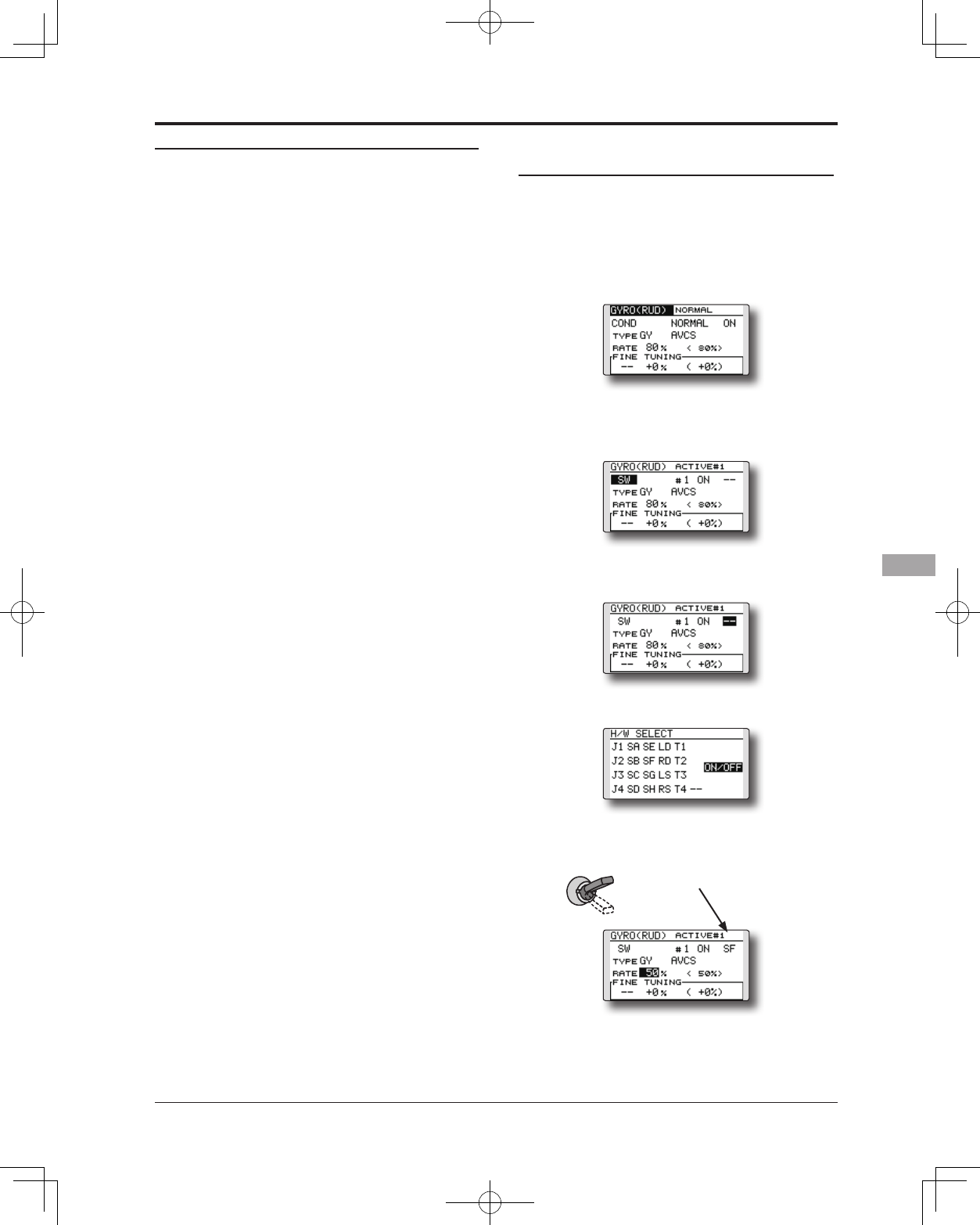
159
<Functions of Model Menu (Helicopter Functions)>
Setting method
●Gyro type selection
Movethecursortothegyrotypeselection
itemandtouchtheRTNbuttontoswitchto
thedatainputmode.Selectthegyrotype
byscrollingthetouchsensor.
[GY]:WhenaFutabaGYgyroisused
[NORM]:WhenotherthanFutabaGYgyrois
used
TouchtheRTNbuttontochangethegyro
typeandreturntothecursormode.
*When a Futaba GY gyro is used and [GY] type is selected,
the sensitivity set value is directly read in both the AVCS
and NORM modes.
●Operation mode selection (GY gyro)
Movethecursortotheoperationmode
selectionitemandtouchtheRTNbutton
toswitchtothedatainputmode.Select
theoperationmodebyscrollingthetouch
sensor.
[AVCS]:AVCSmode
[NORM]:Normalmode
TouchtheRTNbuttontochangethe
operationmodeandreturntothecursor
mode.
●Sensitivity setting
Movethecursortotherateitemand touch
theRTNbuttontoswitchtothedatainput
mode.
Adjustthesensitivitybyscrollingthetouch
sensor.
Initialvalue:80%
Adjustmentrange:0~100%
*When the RTN button is touched for one second, the
sensitivity is reset to the initial value.)
TouchtheRTNbuttontoreturntothecursor
mode.
●Fine tuning VR settings
Movethecursortothe[--]itemandtouch
theRTNbuttontoaccesstheselection
screen.Selectthecontrol.
*For a description of the switch selection method, see the
description at the back of this manual.
Movethecursortotherateitemand touch
theRTNbuttontoswitchtothedatainput
mode.
Adjustthetrimratebyscrollingthetouch
sensor.
Initialvalue:0%
Adjustmentrange:-20~+20%
*When the RTN button is touched for one second, the
sensitivity is reset to the initial value.)
TouchtheRTNbuttontoreturntothecursor
mode.
<EXAMPLE>Rudder gyro gain is changed with
a switch (SF) irrespective of condition.
Generally,gainisinterlockedwithcondition
andchangesarate.
Howtochangetworatesinthesame
conditionhere.
1.Select[GYRO]attheModelmenuand
accessthesetupscreenshownbelowby
touchingtheRTNbutton.
2.Movethecursortothe[COND]item
andtouchtheRTNbuttontoaccessthe
selectionscreen.Selectthe[SW].Touchthe
RTNbuttontoreturntothecursormode.
3.#numbershowsthepresentswitchstate.In
thestateof#1acursorismovedto[--]and
RTNispushed.
4.[SF]ischosenby[H/WSELECT]andthena
topisturnedON.
5.[TYPEGY]and[RATE]ofastateof"#1=SF
top"aresetup.
6.Itisasetupof"#2".Movethecursortothe
[#1]itemandtouchtheRTNbuttonto
accesstheselectionscreen.Selectthe[#2].
TouchtheRTNbuttontoreturntothecursor
mode.
SF : Top = #1
●Thenumber
ofaSWstate
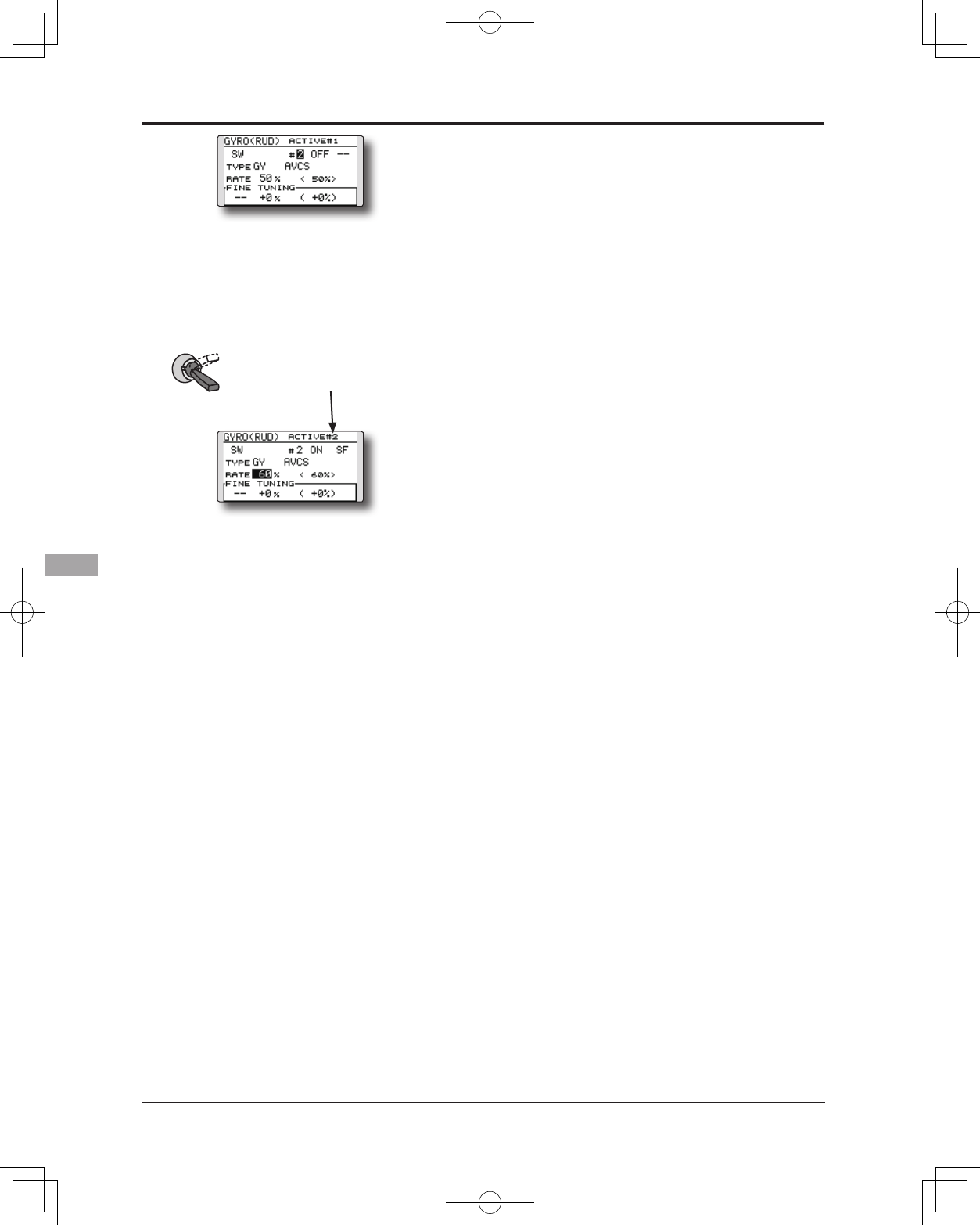
160 <Functions of Model Menu (Helicopter Functions)>
7.Movethecursortothe[--]itemandtouch
theRTNbutton.
8.[SF]ischosenby[H/WSELECT]andthena
bottomisturnedON.theRTNbutton.
9.[TYPEGY]and[RATE]ofastateof"#2=SF
bottom"aresetup.
*If 3 position switch is chosen, the change of 3 rates can be
performed.
*Combined use of two or more switches cannot be performed.
SF : Bottom = #2
●Thenumber
ofaSWstate
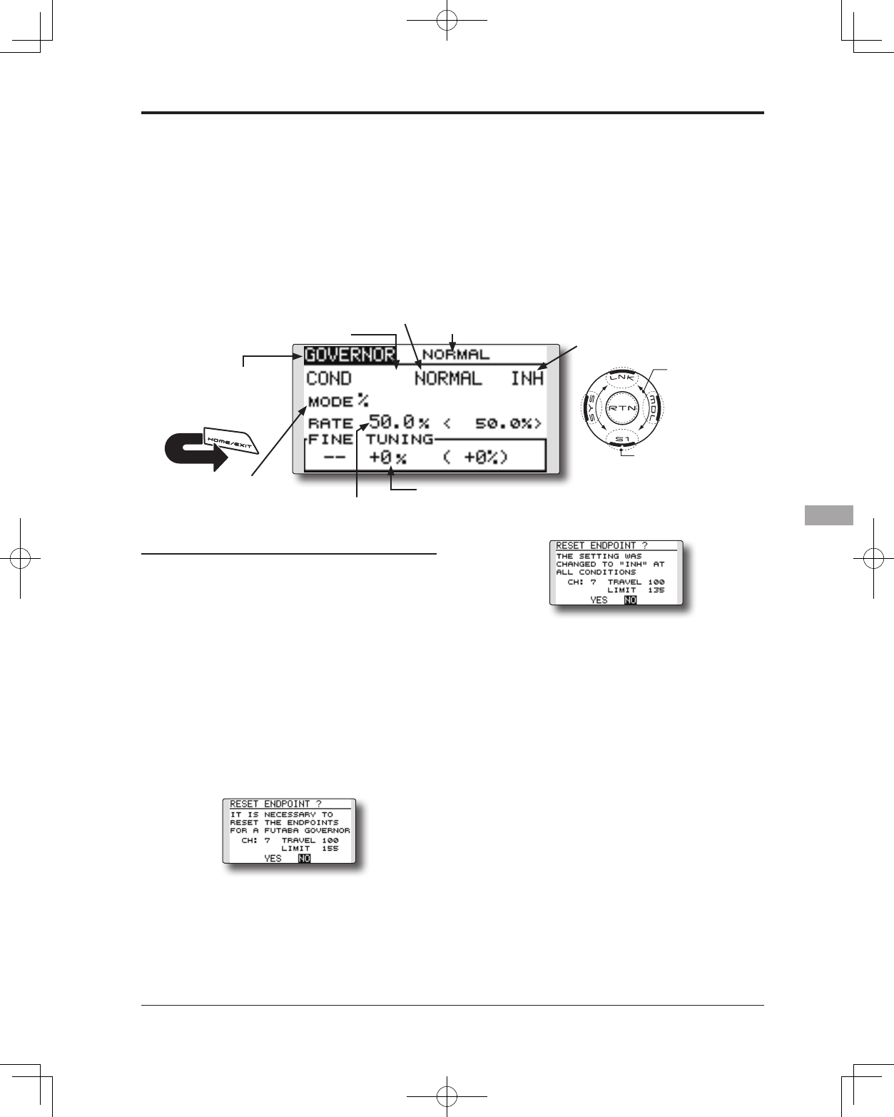
161
<Functions of Model Menu (Helicopter Functions)>
●Selectthefunctionname
andreturntotheModel
menubytouchingthe
RTNbutton. Orthe
HOME/EXIT buttonis
pushed.
<SensorTouch™>
RETURN
GOVERNOR mixing
When using a Futaba GV-1/GY701/CGY750
governor, this function is used to switch the RPM
of the helicopter's rotor head. The rotor head speed
can be switched with each condition or the switch.
*The governor is used by connecting the governor speed
setting channel to CH7 (initial setting).
*When using an independent governor [ON]/[OFF] switch,
connect the AUX([ON]/[OFF]) connector of the governor to
CH8 and set the switch to CH8 (Governor2) at the Function
menu of the Linkage Menu.
Note: Always set (Control) and (Trim) to [--]
for [Governor] of the Function menu of the
Linkage menu.
●Select[GOVERNOR]attheModelmenuandaccess
thesetupscreenshownbelowbytouchingtheRTN
button.
Scrolling
●Movingcursor
●Selectingmode
●Adjustingvalue
●Tonextpage
(Currently selected condition name)
●Unitdisplayselection:
[%]/[rpm]
●Setupscreenselection
●ACT/INH:INH(initialsetting)
●FinetuningVRsettings
●RPMadjustment
●Condition/Switchselection
Setting method
●Activate the mixing
Whenusingthisfunction,movethecursorto
the[INH]itemandtouchtheRTNbuttonto
switchtothedatainputmode.
SelecttheACTmodebyscrollingthetouch
sensor.
*The display blinks.
TouchtheRTNbuttontoactivatethemixing
andreturntothecursormode.(ONis
displayed.)
WhentheGovernorischangedfromthe
defaultinhibited(INH)statetotheactive
(ACT)state,theendpointmenuwillbe
displayedanditispossibletoutilizethe
endpointsforthisgivencondition.
*When the function is set ON/OFF at the governor setup
screen, the governor rpm setting channel end point servo
travel and limit point are now initialized.
*When changed from INH to ACT (ON), the servo travel is
initialized to 100 and the limit point is initialized to 155.
*When operation is changed to INH at all conditions, the
servo travel is initialized to 100 and the limit point is
initialized to 135.
UsetheSensorTouchtoscrolltoeitherYES
(incorporatethedefaultendpoints)orNO
(endpointsarenotutilized.PresstheReturn
(RTN)buttontoconrmtheselectionmade.
●RPM adjustment
Movethecursortotherateitemand touch
theRTNbuttontoswitchtothedatainput
mode.
Adjusttherpmbyscrollingthetouchsensor.
Initialvalue:50%(1500rpm)
Adjustmentrange:OFF,0~110%(OFF,
700~3500rpm)
*When the RTN button is touched for one second, the
sensitivity is reset to the initial value.)
TouchtheRTNbuttontoreturntothecursor
mode.
●Unit diplay selection
MovethecursortotheUNITitemandtouch
theRTNbuttontoswitchtothedatainput
mode.Selecttheunitbyscrollingthetouch
sensor.
TouchtheRTNbuttontochangethe
operationmodeandreturntothecursor
mode.
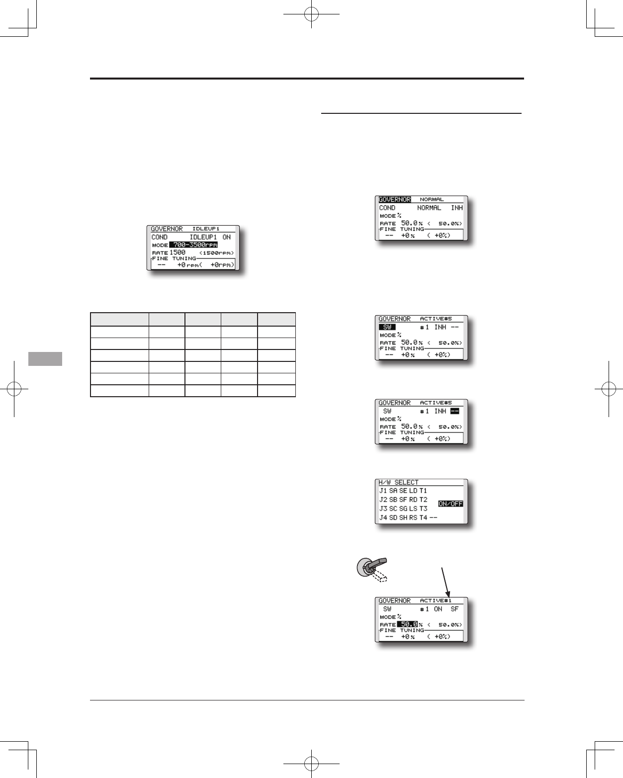
162 <Functions of Model Menu (Helicopter Functions)>
●Diplay mode selection
*When [rpm] mode is selected above setting, the display
mode can be selected.
* There is no change in the transmitter output even when the
"MODE" is changed. Calibration should be performed via
the governor.
* In order to use the Governor function of the T14SG, it is
necessary to change the settings on the governor for the low
side 700 rpm mode.
WhentheMODEoftheGovernorscreen's
modelmenuischanged,thechangeisalso
indicatedon-screen.
The chart below indicates the mode percentage and
the corresponding RPM.
MODE 0% 50% 100% 110%
1000-2000rpm 1000rpm 1500rpm 2000rpm 2100rpm
1000-2500rpm 1000rpm 1500rpm 2500rpm 2700rpm
1000-3500rpm 1000rpm 1500rpm 3500rpm 3900rpm
700-2000rpm 700rpm 1500rpm 2000rpm 2100rpm
700-2500rpm 700rpm 1500rpm 2500rpm 2700rpm
700-3500rpm 700rpm 1500rpm 3500rpm 3900rpm
●Fine tuning VR settings
Movethecursortothe[--]itemandtouch
theRTNbuttontoaccesstheselection
screen.Selectthecontrol.
*For a description of the switch selection method, see the
description at the back of this manual.
Movethecursortotherateitemand touch
theRTNbuttontoswitchtothedatainput
mode.
Adjustthetrimratebyscrollingthetouch
sensor.
Initialvalue:0%(0rpm)
Adjustmentrange:-20~+20%(-200~+200rpm)
*When the RTN button is touched for one second, the
sensitivity is reset to the initial value.)
TouchtheRTNbuttontoreturntothecursor
mode.
<EXAMPLE>RPM rate is changed with a
switch (SF) irrespective of condition.
Generally,RPMrateisinterlockedwith
conditionandchangesarate.
Howtochangetworatesinthesame
conditionhere.
1.Select[GOVERNOR]attheModelmenu
andaccessthesetupscreenshownbelow
bytouchingtheRTNbutton.
2.Movethecursortothe[COND]item
andtouchtheRTNbuttontoaccessthe
selectionscreen.Selectthe[SW].Touchthe
RTNbuttontoreturntothecursormode.
And[INH]issetto[ACT].
3.#numbershowsthepresentswitchstate.In
thestateof#1acursorismovedto[--]and
RTNispushed.
4.[SF]ischosenby[H/WSELECT]andthena
topisturnedON.
5.[MODE]and[RATE]ofastateof"#1=SF
top"aresetup.
6.Itisasetupof"#2".Movethecursorto
the[#1]itemandtouchtheRTNbutton
toaccesstheselectionscreen.Selectthe
[#2].TouchtheRTNbuttontoreturntothe
cursormode.And[INH]issetto[ACT].
SF : Top = #1 ●Thenumber
ofaSWstate
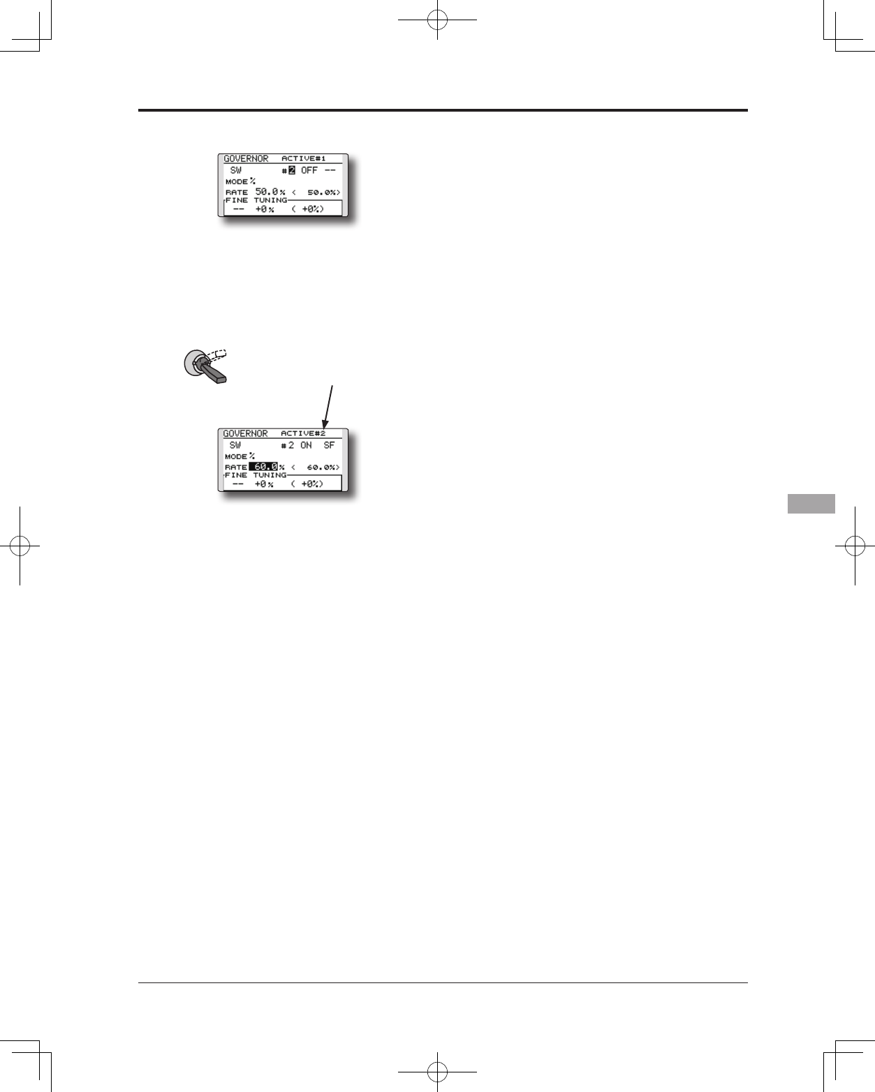
163
<Functions of Model Menu (Helicopter Functions)>
7.Movethecursortothe[--]itemandtouch
theRTNbutton.
8.[SF]ischosenby[H/WSELECT]andthena
bottomisturnedON.theRTNbutton.
9.[MODE]and[RATE]ofastateof"#2=SF
bottom"aresetup.
*If 3 position switch is chosen, 3 rate changes can be
performed.
*Combined use of two or more switches cannot be performed.
SF : Bottom = #2
●Thenumber
ofaSWstate
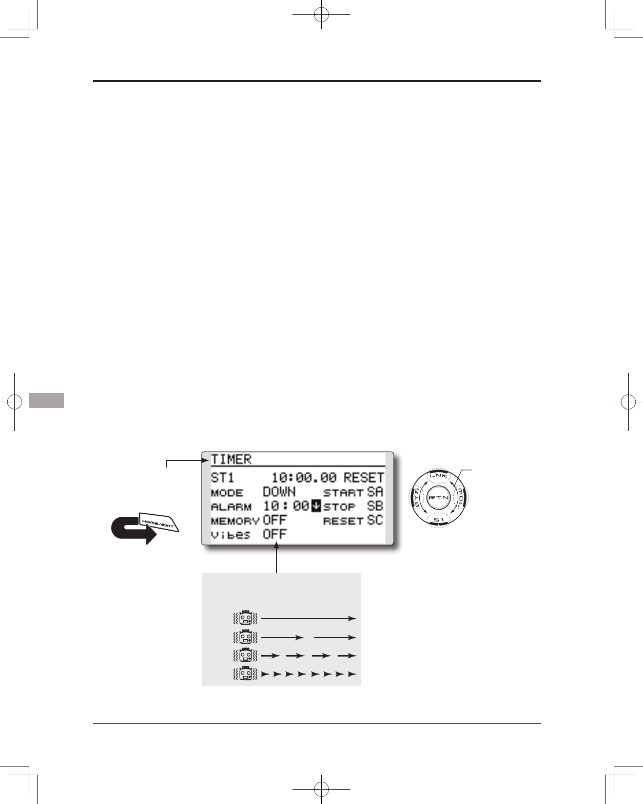
164 <Appendix>
●Selectthefunctionname
andreturntothehome
screenbytouchingthe
RTNbutton. Ora HOME/
EXIT buttonispushed.
<SensorTouch™>
RETURN
TIMER ST1/ST2 Timersetting
The Timer function may be set for any desired
time, i.e. engine run time, specified times for
competitions, etc. Two independent timers are
provided for your use. The timers are stored
independently with each model, meaning that
when you switch between model setups, the timer
associated with the new model is brought up
automatically.
The timers may be set to start and stop from the
motion of any switch or stick. You may set the ON and
OFF directions freely. Each timer has a capacity of up
to 59 minutes 59 seconds.
Each timer may be set for count-down (DOWN
mode) or count up (UP mode) operation with a
target time or for count up to 99 hours 59 minutes
(HOUR mode).
If a target time is set and the timer reaches the set
time, a buzzer sound for each count is generated.
Countdown timers sound one short beep during
the last twenty seconds and two short beeps during
the last ten seconds before reaching the target, then
a long tone at the target time, and continue counting
with displaying a minus (-) sign. Count-up timers
also beep the last twenty and ten seconds, beep the
target time, and keep counting upwards until shut
down.
A mode which sounds an alarm each minute of
the time remaining up to the timer alarm time can
be selected.
The HOUR mode is convenient when used in
engine maintenance period and other long-term
measurements.
* When the HOUR mode is set, "xx (hour): xx (minute)"
is displayed on the count time display. Seconds are not
displayed.
* When the HOUR mode is set, ":" blinks each second during
timer operation.
* When the HOUR mode is set, the alarm function is
inhibited.
●SelectST1orST2atthehomescreenand
callthesetupscreenshownbelowby
touchingtheRTNbutton.
Scrolling
●Movingcursor
●Selectingmode
●Adjustingvalue
TYPE 1
TYPE 2
TYPE 3
TYPE 4
"Vibes" type
If the following types are selected, the
transmitter will vibrate during the warning.
165
<Appendix>
Timer setting
●Up timer/down timer setting
Movethecursortothe[MODE]itemand
touchtheRTNbuttontoswitchtothedata
inputmode.
Selectthemodebyscrollingthetouchsensor
andtouchtheRTNbutton.
[UP]:Uptimer
[DOWN]:Downtimer
[HOUR]:Hourmodetimer
●Timer time setting
Movethecursortothe[ALARM]itemand
touchtheRTNbuttontoswitchtothedata
inputmode.
Setthetimebyscrollingthetouchsensor.
[00]:[00]:[min]:[sec]
TouchtheRTNbuttontoendtheadjustment
andreturntothecursormode.
●Switch setting
Movethecursortotheitemoftheswitchyou
wanttoset,accesstheswitchsetupscreen
bytouchingtheRTNbutton.Selecttheswitch
andONdirection.
[For a detailed description of the setting method, see [Switch
Setting Method] located on the next page.]
[START]:Startswitch
[STOP]:Stopswitch
[RESET]:Resetswitch
●Memory setting
Movethecursortothe[MEMORY]itemand
touchtheRTNbuttontoswitchtothedata
inputmode.
Selectthemodebyscrollingthetouchsensor
andtouchtheRTNbutton.
[OFF]:MemoryfunctionOFF
[ON]:Modewherethetimerisnotresetwhen
turnedpoweroffandswitchedthemodel.
●A mode which sounds an alarm each minute
can be selected.
Changethesettingusingthe""button(or
""button).
"":Alarmsoundseachminuteofthetime
elapsedfromtimerstart.(Conventional
mode)
"":Alarmsoundseachminuteofthetime
remaininguptothealarmtime.
Timer operation
● TimerST1andST2arestarted/stoppedby
pre-selectedstart/stopswitch.
● Toresetatimer,operatethepre-selected
resetswitch,ormovethecursortothe[RESET]
displayonthetimerscreenandtouchthe
RTNbutton.
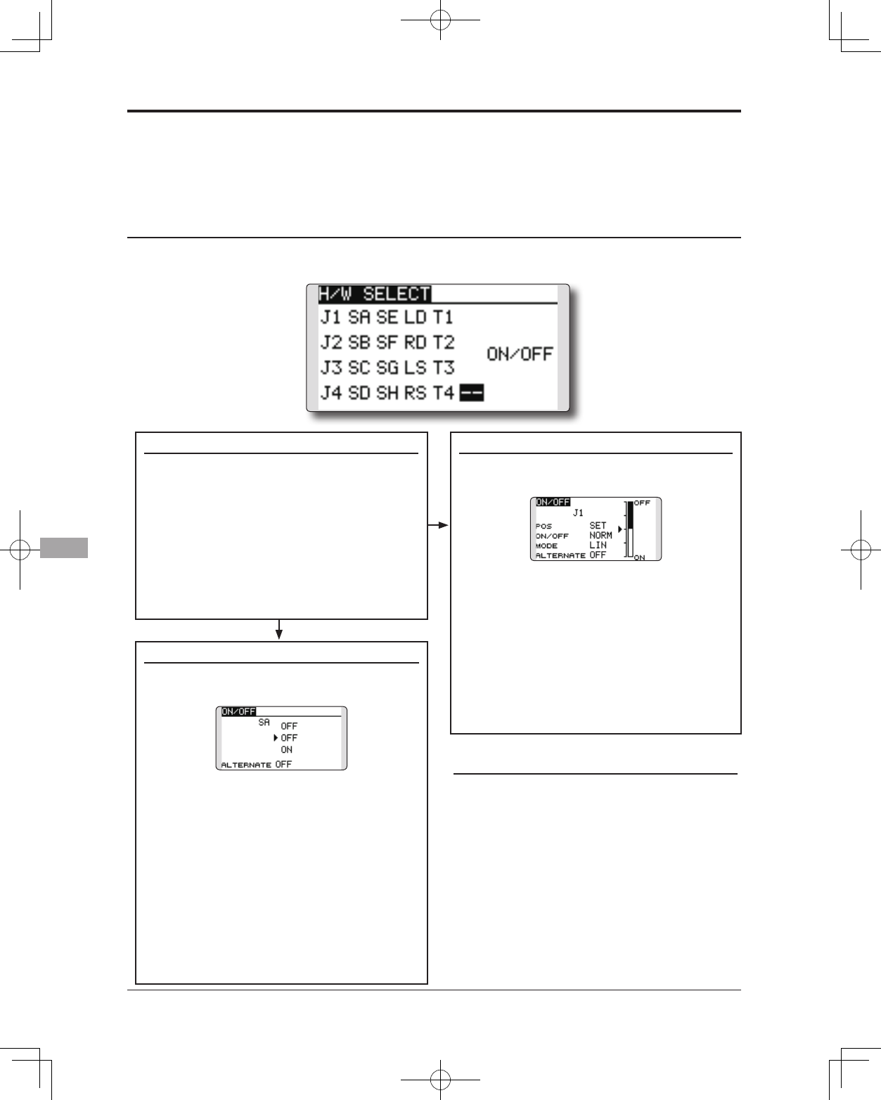
166 <Appendix>
The various functions used in the T14SG can
be activated by a switch. For the purposes of this
manual, a stick position, VR position, etc. shall be
commonly referred to as a switch in all cases. That
(Switchselectionscreenexample)
When switch is selected
When switch was selected, ON/OFF position
setting is also performed.
*The ON/OFF setting state of each position is displayed.
1.WhenyouwanttochangetheON/OFF
setting,usethetouchsensortomovethe
cursorandtouchtheRTNbuttontoswitch
tothedatainputmode.SwitchtheON/
Offdisplaybyscrollingthetouchsensor.
*ON/OFF display blinks.
2.WhentheRTNbuttonistouched,theON/
OFFsettingischanged.(TouchtheS1
buttontostopthechange.)
3.Toreturntothepreceedingscreen,move
thecursortothe[ON/OFF]atthetopof
thescreenandtouchtheRTNbutton.
When stick, trim lever, or knob selected
When a stick, trim lever, or knob is used as a
switch, two operation modes can be selected:
1.Whenyouwanttochangethemode,
movethecursorto[MODE]itemand
touchtheRTNbuttontoswitchtothe
datainputmode.Switchthedisplay
tothemodeyouwanttochangeby
scrollingthetouchsensorandthenmake
thechangebytouchingtheRTNbutton.
●
Mode:[LIN]/[SYM]
*
Set the ON/Off point by the method described on the next page.
Switch selection
1.Usethetouchsensortomovethecursor
(highlights)totheswitchyouwantto
selectandtouchtheRTNbutton.
*The switch blinks.
2.Toreturntothepreceedingscreen,move
thecursortothe[H/WSELECT]atthetop
ofthescreenandtouchtheRTNbutton.
Or,movethecursortothe[ON/OFF]and
calltheON/OFFpositionsettingscreenby
touchingtheRTNbutton.
Alternate mode setting
●ALTERNATE
mode:[OFF]/[ON]
1.Movethecursortothe[ALTERNATE]item
andtouchtheRTNbuttontoswitchtothe
datainputmode.
2.Changetothemodeyouwanttosetby
scrollingthetouchsensor.
*The mode display blinks.
3.TouchtheRTNbutton.(TouchtheS1button
tostopthechange.)
4.Toreturntothepreceedingscreen,move
thecursortothe[ON/OFF]atthetopofthe
screenandtouchtheRTNbutton.
Switch Setting Method
Switch selection
When a switch is selected at a mixing function, etc., the selection screen shown below is called.
is, whenever the manual indicates that something is
operated via a switch, it is possible for the user to
activate this setting via a stick, stick position, etc.
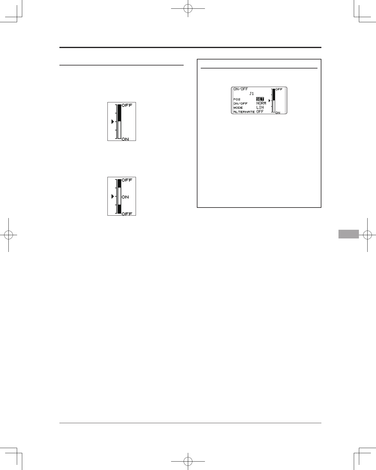
167
<Appendix>
Operation modes
The operation modes available when stick, trim
lever, or knob was selected are described below.
Linear mode [LIN]
This mode sets ON/OFF to the left or right (up
or down) with the set point as the reference.
Symmetrical mode [SYM]
Left and right (up and down) operations are
symmetrical near the neutral position. For instance,
when you want to switch D/R with the aileron
stick, when the stick is moved to the left or right,
DR can be turned on at the same position.
Shifting the ON/Off point
The ON/OFF point can be shifted. ON/OFF at
a free position can be changed.
●Blackrange:OFFrange
●Whiterange:ONrange
[Setting method]
1.First,usethetouchsensortomovethe
cursortothe[POS]item.
2.Movethestick,trimlever,orknobtothe
pointyouwanttochangeandtouchthe
RTNbutton.Thepointisshifted.
3.Toreturntothepreceedingscreen,move
thecursortothe[ON/OFF]atthetopof
thescreenandtouchtheRTNbutton.
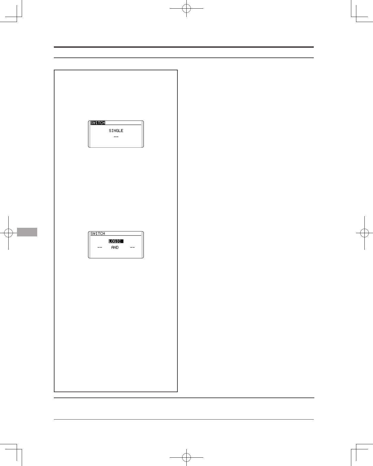
168 <Appendix>
FUTABA CORPORATION Phone: +81 475 32 6982, Facsimile: +81 475 32 6983
1080 Yabutsuka, Chosei-mura, Chosei-gun, Chiba-ken, 299-4395, Japan
©FUTABA CORPORATION 2012, 10 (1)
Logic mode
AND:WhenbothswitchesareON,the
conditionisON.
OR:WheneitherswitchisON,thecondition
isON.
EX-OR:Whenthetwoswitchesarein
differentstates,theconditionisON.
Switch mode selection
1.Movethecursortothe[SINGLE]itemand
touchtheRTNbuttontoswitchtothedata
inputmode.
2.Selectthe[LOGIC]byscrollingthetouch
sensor.
*[LOGIC] display blinks.
3.TouchtheRTNbuttontochangetothe
logicswitchmode.
(Logicswitchsettingscreen)
Logic mode selection
1.Movethecursortothelogicmodeitem
andtouchtheRTNbuttontoswitchtothe
datainputmode.
2.Selectthelogicmodebyscrollingthe
touchsensor.[AND,ORorEX-OR]
*The mode display blinks.
3.TouchtheRTNbuttontochangetothe
logicmode.
Swich selection
1.Selecttherightandleftswitchrespectively.
(Refertothedescriptionattheprevious
page.)
Toreturntothepreceedingscreen,move
thecursortothe[SWITCH]atthetopofthe
screenandtouchtheRTNbutton.
Logic switch (Condition Select function only)
The logic switch function lets you turn operation on and off by combining two switches.