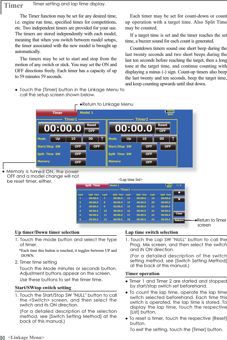
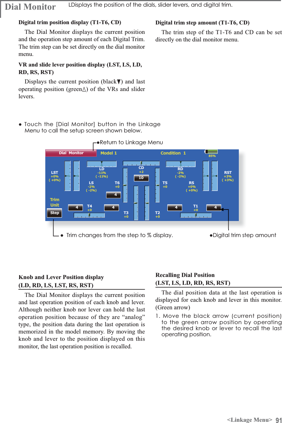
Futaba T18MZ-24G Radio Control User Manual
Futaba Corporation Radio Control
UserManual.wiki
>
Futaba
>
T18MZ-24G User Manual
>
User manual-2(Page 31-100)
Contents
1.
User manual-1(page 1-30)
2.
User manual-2(Page 31-100)
3.
User manual-3(Page 101-162)
User manual-2(Page 31-100)
Navigation menu
Upload a User Manual
Namespaces
Wiki Guide
HTML
PDF
Info
Views
User Manual
Discussion / Help
Navigation
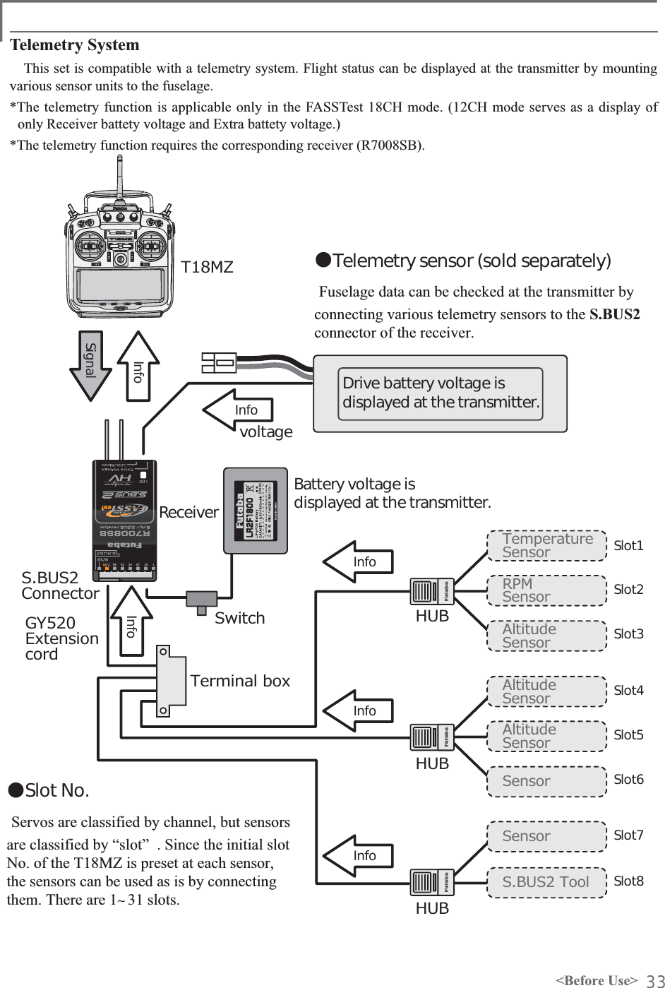
![32 <Before Use>S.BUS2 System S. BUS2, extend the conventional S.BUS system and support bidirectional communication systems, such as a telemetry sensor.Receiver connector S.BUS ServoS.BUS Gyro telemetry sensorS.BUS 䂾㬍S.BUS2 㬍䇭䋨 㶎䋩 䂾S.BUS device setting S.BUS servos or a telemetry sensor can be connected to the T18MZ and channel setting (slot setting) and other settings can be memorized at the S.BUS device.S.BUS2 TABLE䋨㶎䋩'RQWFRQQHFW6%866HUYRS.BUS Gyro to BUS2 connector. HUB or Y-adaptor(S.BUS Servo)S.BUS device(telemetry sensor)ReceiversBatteryT18MZ&RQQHFWWKH6%86GHYLFHDQGEDWWHU\\RXZDQWWRVHWZLWKDZD\KXERUZD\FRUGDVVKRZQLQWKHÀJXUH7XUQRQWKHWUDQVPLWWHUSRZHU&DOOWKHVHWXSVFUHHQ䇭6HUYR6\VWHP0HQX→6%866HUYR䇭6HQVRU/LQNDJH0HQX→6HQVRU3HUIRUPVHWWLQJLQDFFRUGDQFHZLWKHDFKVFUHHQ7KLVPHPRUL]HVWKHFKDQQHOVORW1RDWHDFK6%86GHYLFHVRLWFDQEHXVHGE\FRQQHFWLQJLWWRWKH6%86FRQQHFWRURIWKHUHFHLYHU](https://usermanual.wiki/Futaba/T18MZ-24G.User-manual-2-Page-31-100/User-Guide-1596898-Page-2.png)
![34 <Basic Operation>BASIC OPERATIONBattery ChargingBefore charging batteries, read the "Cautions for handling battery and battery charger" in the section "For your safety".Charging the transmitter LT2F3500XH lithium-polymer batteryDangerThe LT2F3500XH lithium-polymer battery is for the T18Mz transmitter only. Do not use it with other devices.Always use the accessory AC adapter to charge the battery.The charging circuit is built into the T18MZ.[Method of charging battery]T18MZAC100V Charge lamp1. Turn off the transmitter power.2. Connect the power plug of the AC adapter to an AC100V outlet.*Don't connect AC plug to T18MZ without connecting with AC100V.3. Open the back lid of the transmitter and insert the plug of the AC adapter into the CHG port.4. The charging monitor of the transmitter lights red.*The LCD screen will come on for several seconds and then go off. It may take several tens of seconds for charging to start after the AC adapter is connected.5. When the battery is fully charged the transmitter monitor will light green. A charge plug is pulled out and an AC adaptor is removed.*After using the AC adapter always disconnect the power cord from the AC outlet.*The charging time when charging a completely discharged battery pack is approximately 2 hours 30 seconds. However, the actual charging time may be different from the above depending on the ambient temperature and state of the battery pack.*If the battery is improperly installed or is faulty, the transmitter monitor will not light and the battery will not be charged.How to charge the Li-Fe battery FR2F1800(Option) for the receiverUse the battery charger that is included in the set.[Method of charging battery]AC100V3S2SMODEL :LBC-4E5Intelligent LiFePO4 for 2S/3S CellsBalance CHARGERRed on, green off : ChargingRed flash : Output short-circuit or wrong polarityGreen on, red off : Charging Full䃂The connector of the battery isconnected with "2S" side ofthe charger.䋨2S sids䋩Charger LBC-4E51. Connect the power cable of the charger to the wall socket (AC outlet).2. Connect the connector to the Li-Fe battery.&RQ¿UPWKDWWKHFKDUJLQJLQGLFDWRU/('ODPS5HGOLJKWV3. Remove the battery after LED lamp Green lighting .*After completing the charge remove the battery from the charger and remove the charger from the wall socket.WarningThe transmitter battery cannot be charged with the receiver charger. Conversely the receiver battery cannot be charged with the transmitter charger.](https://usermanual.wiki/Futaba/T18MZ-24G.User-manual-2-Page-31-100/User-Guide-1596898-Page-4.png)
![35<Basic Operation>How to turn ON/OFF the power of the transmitterWindows®&(LVLQVWDOOHGDVDEXLOWLQRSHUDWLQJsystem in the T18MZ transmitter. Compared to the conventional system, the T18MZ takes extra time for internal processing when it is turned on/off.When turning on the power of the transmitter1. Make a throttle stick slow.2. Turn on the power switch of the transmitter.$IWHULQLWLDOL]DWLRQRIWKHWUDQVPLWWHULVRYHU/('PRQLWRUturns on Purple.*If a throttle stick turns on by the high speed side (1/3 or more), warning will become. If it returns slowly, warning will stop and will become a "Transmit ?" screen.*If you push the button "NO", then the transmitter will not emit radio waves.*If you push the button "Yes", then the transmitter will emit radio waves.Start-up time; The time required for initializing the internal circuit of the transmitter varies between the previous time you turned off the transmitter and the time you will turned on the power. There are two “start up” modes for your transmitter, see below:Cold start;If you turn on the transmitter more than four hours after you last turned it off, the mode is “Cold start”. “Cold start” is normal for the first initial power up of the day. It will take about 30 seconds to be ready for use, as it takes time to initialize the internal circuit of the transmitter. Hot start;If you turn on the transmitter less than four hours after you last turned it off, the mode is “Hot start”. Since initialization has been partly completed, the transmitter will be ready to use in several seconds. ³+RWVWDUW´WDNHVSODFHXVXDOO\DWDVHFRQGÀLJKWRUODWHUÀLJKWLQWKHGD\WarningOnce you turn on the power, never shut off the power switch until the power becomes stable (or XQWLOWKH¿UVWVFUHHQVKRZVXS,I\RXWXUQRIIthe power switch while the transmitter is going through the initialization process, the data could be damaged. Note: The start-up time may be a little bit slower when the SD card is installed compared to when the card is not.How to stop the transmitterTurn off the power switch of the transmitter. The internal circuit of the transmitter starts the shut down process including saving the set-up data. The /('ZLOOEOLQN\HOORZZKLOHWKHWUDQVPLWWHULVLQthe shutdown process. Once you turn off the power, never operate the power switch until the power shutdown process is fully completed. If you turn on the power switch again while the transmitter is still in the process of power shutdown, the data could be damaged.The right switch is pushed.It turns it off by pushing 2 pieces simultaneously.It turns it off by pushing 1 pieces pushes for a long time.or](https://usermanual.wiki/Futaba/T18MZ-24G.User-manual-2-Page-31-100/User-Guide-1596898-Page-5.png)
![36 <Basic Operation>Registration of the user's nameT18MZ transmitter can register user's name. How to register user's name1. Turn on the power of the transmitter.2. Push the area of the user's name shown on the home screen or the "user's name" in the linkage menu. Then the User's Name Set screen will pop up.85%User Name Model1User Name User ID Secure Mode Futaba Corporation0000System3. Push the user's name. Then the keyboard will pop up. You can use up to 32 characters as a user's name. Use the keyboard on the screen to enter user's name.space keyEnter and Exit : [Return] Key, Cancel and Exit : [ESC] Key3LHDVHLQSXWXVHUQDPH۹&KDUDFWHUVFutaba Corporation4. Push "Return" key to return to the previous screen after entering the user's name.(If you want to protect the user's name)If you don't want anybody else to change your user's name, set your ID in the following way.*Please be aware that you will not able to change user's name if you forget your password. 1. Make sure that the security mode is "User's name", and then push the User ID button.2. Enter your password, using keyboard on the screen.You will need to enter your password for changing the user's name from the next time you turn on the power of the transmitter.(YHQLI\RXHQWHUWKHVDPHFKDUDFWHU\RXUSDVVZRUGZLOOEHidentified differently depending on whether you are using "Transform" mode or "Direct" mode for inputting.As the internal circuit of the transmitter stays on the standby mode for 4 hours after turning off the power, some part of the circuit is consuming current. When you turn on the power during this period, the power starts in “Hot mode”. But if more than four hours pass after shutting down the power, the power supply will completely shut down the internal circuit. When you turn on the power after this point, the power starts in “Cold start mode”. How to reset softwareIf the screen freezes for some reason and you cannot edit, the transmitter power supply is not shut off even if you turn OFF the power switch. You will need to use the remove the battery and reinsert it again. In this case, the power restarts in “Cold PRGH´(YHQWKRXJKWKHVFUHHQIUHH]HVDOOWKHother functions for radio control operation remain operative.](https://usermanual.wiki/Futaba/T18MZ-24G.User-manual-2-Page-31-100/User-Guide-1596898-Page-6.png)
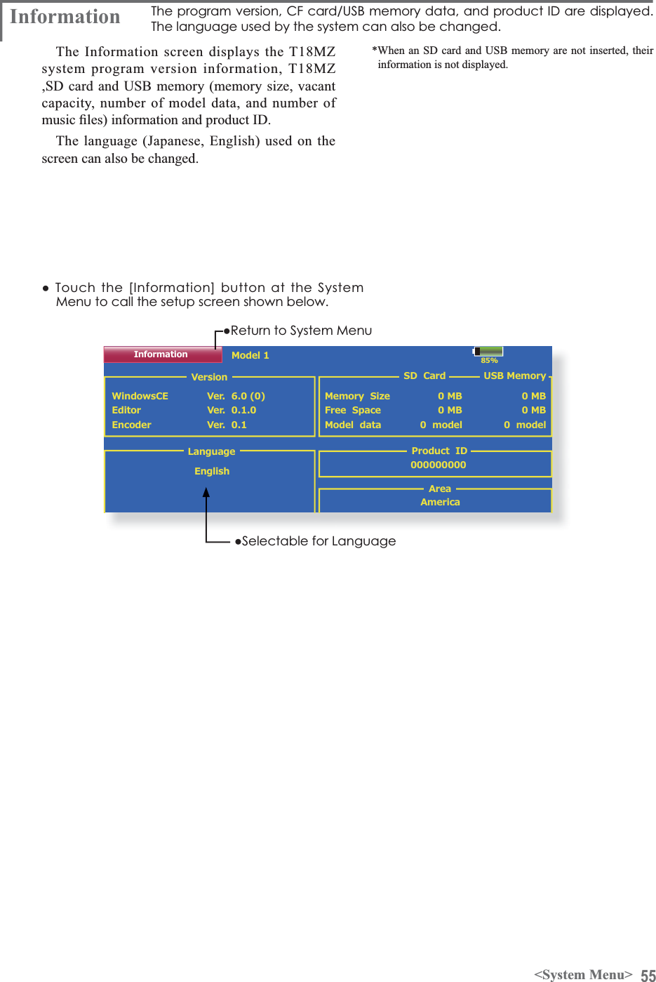
![39<System Menu>SYSTEM MENUSystem Menu functions table[Trainer]: Starts and sets the trainer system.[Display]: Display adjustment and auto power off setting.[Date & Time]: Sets the date and time (system clock setting) and resets the timer.[User Name]: User name registration and ID Pin number.[Switch]: Toggle switch type setting (Set when the switch is replaced.)[H/W Setting]: Hardware reverse / Stick setting / Calibration.[Sund Volume]: This volume is adjusted. Key Operation/Error Warning/Trim&Center Click/Timer Event.>3OD\HU@5HSURGXFWLRQRIPXVLF¿OH[Camera]: Function that takes pictures with a camera.[S.BUS Servo]: S.BUS servo setting.[Information]: Displays the program version, SD card information, and product ID.[Range Check]:The output of the transmitter is lowered, and the Range checked.The System Menu sets up functions of the transmitter, this does not set up any model data.ŏ:KHQWKH6\VWHP0HQXEXWWRQLVWRXFKHGWKHPHQXVKRZQEHORZLVFDOOHG&DOOWKHVHWXSVFUHHQE\SUHVVLQJWKHIXQFWLRQ\RXZDQWWRVHWXSŏ5HWXUQWR+RPHVFUHHQ](https://usermanual.wiki/Futaba/T18MZ-24G.User-manual-2-Page-31-100/User-Guide-1596898-Page-9.png)
![43<System Menu>Model 185%Display-+-+30Min.1Min.$XWR3RZHURíWLPHBacklight decreaseBack color Touch screen%DFNOLJKWGHFUHDVHWLPHBacklightTEXT TEXT TEXT TEXT TEXT Cal.Auto power off time setting$GMXVWWKHDXWRSRZHURIIWLPHZLWKWKHOHIWDQGULJKWVLGHEXWWRQV*When the time the transmitter is inactive exceeds the set time, the power is turned off automatically. This time can be set up to 1 hour in 10 minutes increments. The auto power off function can also be deactivated.*An audible alarm is sounded and an alarm screen is displayed from 3 minutes before auto power off and the time remaining until auto power off is displayed. When a stick or switch is operated while the alarm screen is being displayed, the alarm is cleared and the display is returned to the home screen.Backlighting brightness adjustment$GMXVWWKHEDFNOLJKWLQJEULJKWQHVVZLWKWKHOHIWDQGULJKWVLGHEXWWRQV*When the right side button is touched, the backlightingbecomes brighter. When the left side button is touched, the backlighting becomes darker.Backlight decrease brightness adjustment$GMXVWWKHEDFNOLJKWGHFUHDVHEULJKWQHVVZLWKWKHOHIWDQGULJKWVLGHEXWWRQV*When the right side button is touched, the backlightingbecomes brighter. When the left side button is touched, the backlighting becomes darker.*It cannot be made brighter than Backlighting brightness adjustment.Backlight decrease time<RXFDQVHWDWLPHSHULRGWRGHFUHDVHWKH/&'EDFNOLJKW7KLVIXQFWLRQFRXQWVWKHSHULRGDisplay/&'VFUHHQDGMXVWPHQWDQGDXWRSRZHURIIVHWWLQJThe following LCD screen adjustments and auto power off setting are possible:ŏ$XWRSRZHURIIWLPHVHWWLQJŏ%DFNOLJKWLQJEULJKWQHVVDGMXVWPHQWŏ%DFNJURXQGFRORUFKDQJHŏ7RXFKSDQHOVFUHHQSRVLWLRQFRUUHFWLRQŏ7RXFKWKH>'LVSOD\@EXWWRQLQWKH6\VWHP0HQXWRFDOOWKHVHWXSVFUHHQVKRZQEHORZŏ5HWXUQWR6\VWHP0HQXWKDWWKHWRXFKSDQHOKDVEHHQQRWRSHUDWHG7KLVWLPHFDQEHVHWE\WHQVHFRQGVWHSV<RXFDQDOVRWXUQRIIWKHEDFNOLJKWGHFUHDVHµLI\RXOLNH*The backlight consumes a large amount of power. We recommend you to turn off the backlight by setting the backlight power-off time to about one minute.*Since the backlighting power consumption is extremely high, we recommend that the backlighting off time be made short.Background color7RXFKWKHEXWWRQRIWKHFRORU\RXZDQWWRFKDQJH7KHUHDUH¿YHEDFNJURXQGFRORUVTouch screen calibration7KLVIXQFWLRQDGMXVWVWKHORFDWLRQRIWRXFKSDQHO7RXFK&DOLEUDWLRQEXWWRQDQGWKHQSUHVV<HVWKHFDOLEUDWLRQVFUHHQZLOOSRSXS7RXFKWKHFHQWHURIWKHFURVVKDLUFXUVRURQWKHVFUHHQZLWKWKHVW\OXVSHQ$VVRRQDVWKHV\VWHPUHFRJQL]HVWKHSRVLWLRQWKHFXUVRUZLOOPRYHRQWRWKHQH[WSRVLWLRQ5HSHDWWKLVSURFHGXUHDVORQJDVWKHFXUVRUPRYHVWRQH[WSRVLWLRQ<RXZLOOGRWKLVILYHWLPHV&DOLEUDWLRQZLOOEHFDUULHGRXWEDVHGRQWKHILYHSRVLWLRQV'LVDSSHDUDQFHRIWKHFURVVKDLUFXUVRUPHDQVWKHFDOLEUDWLRQKDVEHHQFRPSOHWHG7RXFKDQ\SRLQWRQWKHVFUHHQWRUHWXUQWRWKHSUHYLRXVVFUHHQ*In ordinary operation, this calibration is not necessary. If you notice the touch panel is not functioning correctly after long use, we recommend you to carry out this calibration.](https://usermanual.wiki/Futaba/T18MZ-24G.User-manual-2-Page-31-100/User-Guide-1596898-Page-13.png)
![45<System Menu>85%User Name Model1User Name User ID Secure Mode Futaba Corporation0000SystemUser Name 8VHUQDPHUHJLVWUDWLRQDQG3,1VHWWLQJThis function registers the T18MZ user name.A PIN can also be set to protect the set data or user name.ŏ7RXFKWKH>8VHU1DPH@EXWWRQDWWKH6\VWHP0HQXWRFDOOWKHVHWXSVFUHHQVKRZQEHORZ*Set the PIN carefully. When a system PIN is set, if youforget the PIN, none of the settings can be changed. In this case, the system must be reset by the Futaba Service Center. ŏ5HWXUQWR6\VWHP0HQXUser name registration:KHQWKH8VHU1DPHER[LVWRXFKHGDNH\ERDUGDSSHDUVRQWKHVFUHHQ(QWHUWKHXVHUQDPHIURPWKLVNH\ERDUG*A user name of up to 32 characters can be entered. *The set user name is displayed on the Home screen.(For a detailed description of the input method, see [User Name Registration/Character Input Method] in the BasicOperation section.)User name or set data protection7RXFKWKH6HFXULW\0RGHEXWWRQDQGVHOHFWWKHPRGH7KHPRGHLVVZLWFKHGHDFKWLPHWKHEXWWRQLVWRXFKHG*User Name: Select when you want to protect the user name only.*System: Select when you want to protect all the set data.:KHQWKHXVHU,'EXWWRQLVWRXFKHGD3,1LQSXWVFUHHQDSSHDUV,QSXWD3,1RIXSWRGLJLWV:KHQWKH5HWXUQNH\LVWRXFKHGWKHGLVSOD\UHWXUQVWRWKHSUHFHGLQJVFUHHQ:KHQWKHWUDQVPLWWHUSRZHULVWXUQHGRIIWKHVHWVHFXULW\PRGHEHFRPHVDFWLYH*When a PIN is set at the user name, it must be entered the next time the User Name screen is opened.When a System PIN is set, a button displaying a key iconappears on the Home screen.When you want to change the setting, touch this button and enter the PIN.,I\RXZDQWWRQXOOLI\\RXUFXUUHQWSDVVZRUGVHWWKHSDVVZRUGWRGHIDXOWYDOXH](https://usermanual.wiki/Futaba/T18MZ-24G.User-manual-2-Page-31-100/User-Guide-1596898-Page-15.png)
![46 <System Menu>85%Switch LockLeverSW Type Posi. Ait/Mom 3P Mom3Posi. Alt.LeverSB 2Posi. Alt.LeverSC 3Posi. Alt.LeverSD 3Posi. Alt.LeverSESW Type Posi. Ait/Mom 3P Mom3Posi. Alt.LeverSF 2Posi.2Posi.2Posi.Alt.LeverSG Alt.LeverSH Mom.SASwitch selection6HOHFWWKHVZLWFKW\SHE\WRXFKLQJWKH>W\SH@EXWWRQFRUUHVSRQGLQJWRWKHVZLWFKWREHUHSODFHG>/HYHU@7RJJOHVZLWFK>%XWWRQ@3XVKEXWWRQ>'LDO@.QREŏ6HWWLQJIRUWRJJOHVZLWFKLVVKRZQDERYH2/3 position selection7RXFKWKH3RVLEXWWRQFRUUHVSRQGLQJWRWKHVZLWFKDQGVHOHFWWKHSRVLWLRQW\SH>3RVL@SRVLWLRQ>3RVL@SRVLWLRQSwitch 7RJJOHVZLWFKW\SHVHWWLQJ6HWWLQJZKHQWKHVZLWFKZDVUHSODFHGIf you modify the location of the switches on the right and left (top) of the transmitter, you should be sure to re-assign functions to the switches for proper operation.A “Lock” is included to prevent settings from being modified by mistake. When you need to change settings, unlock this by pressing “Lock” it will then read ”Unlock” and you can make changes as required.ŏ7RXFKWKH>6ZLWFK@EXWWRQDWWKH6\VWHP0HQXWRFDOOWKHVHWXSVFUHHQVKRZQEHORZŏ5HWXUQWR6\VWHP0HQX[Alt/Mom] mode selection6HOHFWWKHRSHUDWLRQPRGHE\WRXFKLQJWKH>$OW0RP@EXWWRQFRUUHVSRQGLQJWRWKHVZLWFK>$OW@$OWHUQDWHW\SH>0RP@6HOIUHWXUQW\SHŏ6HOHFWLRQRIWKH>0RP@PRGHZLWKDSRVLWLRQW\SHVZLWFKLVVKRZQDERYH"3P Mom" mode selection6HOHFWWKHRSHUDWLRQPRGHE\WRXFKLQJWKH30RPEXWWRQFRUUHVSRQGLQJWRWKHVZLWFK>6LQJOH@2QHVLGHVHOIUHWXUQW\SH>'XDO@%RWKGLUHFWLRQVVHOIUHWXUQW\SH](https://usermanual.wiki/Futaba/T18MZ-24G.User-manual-2-Page-31-100/User-Guide-1596898-Page-16.png)
![50 <System Menu>Music playback7KH70=WUDQVPLWWHUFDQSOD\EDFNWKHZPDPXVLF¿OHVVWRUHGLQWKH6'FDUGDQG86%PHPRU\You can listen to them through the built-in speaker or a headphone by the earphone plug.[Important notice]%HIRUHGRZQORDGLQJ¿OHVIURP\RXU3&LQWRWKHSD card, insert the SD card into the transmitter and turn on the power of the transmitter. Then the following folders will be automatically FUHDWHGLQWKH6'FDUG:KHQ\RXGRZQORDG¿OHVIURP\RX3&FRS\DQGSDVWHWKH¿OHVLQWRWKHLUFRUUHVSRQGLQJ¿OHV%03SLFWXUHÀOHV:0$PXVLFÀOHV:$9VRXQGÀOHV02'(/PRGHOGDWDÀOHV3XVKWKH0XVLF3OD\EDFNEXWWRQRQWKHKRPHVFUHHQWRFDOOWKHIROORZLQJVHWXSVFUHHQ5HWXUQWRWKHKRPHVFUHHQ%XWWRQWRVHOHFWHLWKHU2QHWLPH3OD\EDFNRU5HSHDW3OD\EDFN%XWWRQWRVHOHFWHLWKHU2QH0XVLF3OD\EDFNRU0XOWLSOH0XVLF3OD\EDFN6:VHOHFWLRQEXWWRQ3XVKWKLVEXWWRQWRFDOOWKH6:VHOHFWVFUHHQDQGFKRRVHWKH0XVLFSOD\EDFNVZLWFK5HIHUWRWKHGHVFULSWLRQLQWKHHQGRIWKLVPDQXDOButtons for music playback<RXFDQSOD\EDFNDQ\PXVLFILOHVOLVWHGRQWKHULJKWVLGHRIWKHVFUHHQ,I\RXDGMXVWWKHYROXPHKHUHLWDGMXVWVQRWRQO\PXVLFSOD\EDFNEXWDOVRRWKHUDSSOLFDWLRQVTo playback$OOWKHPXVLFÀOHVVDYHGLQWKH&)FDUGZLOOEHVKRZQKHUH3XVKWKHILOHQDPHWRVHOHFWWKHPXVLFILOH\RXZDQWWRKHDU8VHWKHEXWWRQVRQWKHOHIWWRSOD\EDFNRUVWRSWKHPXVLF3OD\EDFNÀOHOLVWPlayback FileFile not found !Model 185%00:00:00 / 00:00:00Sel.SWPlayer-+Player](https://usermanual.wiki/Futaba/T18MZ-24G.User-manual-2-Page-31-100/User-Guide-1596898-Page-20.png)
![53<System Menu>S.BUS Servo Description of function of each parameter,'Displays the ID of the servo whose parameters are to be read. It cannot be changed.&KDQQHOChannel of the S.BUS system assigned to the servo. Always assign a channel before use.5HYHUVHThe direction in which the servo rotates can be changed.6HUYRW\SHWhen “Retractable” is selected and the servo has been continuously stopped for 30 seconds, the dead band expands and unnecessary hold current due to external force is eliminated. When a new control signal enters, normal operation is resumed. When using the servo as a landing gear servo, select “Retractable”. Also adjust the servo travel to match the landing gear movement range.6RIW6WDUWRestricts operation in the specified direction the instant the power is turned on. By making this setting, only the first operation when the power is turned on slowly moves the servo to the specified position.6WRS0RGHThe state of the servo when the servo input signal is lost can be specified. The "Hold" mode setting holds the servo in its last commanded position even if using AM or FM system.6PRRWKHUThis function changes smoothness of the servo operation relative to operation signal changes. Normally use at Smooth setting. Especially, select the "OFF" mode when quick operation is necessary.1HXWUDO2IIVHWThe neutral position can be changed. When the neutral offset is large value, the servo's range of travel is restricted on one side.6SHHG&RQWUROSpeeds can be matched by specifying the operating speed. The speed of multiple servos can be matched without being affected by motor fluctuations. This is effective for load torques below the maximum torque.However, note that the maximum speed will not be exceeded even if a speed over the maximum speed of the servo at each operating voltage is set.'HDGEDQGThe dead band angle at stopping can be specified.[Relationship between dead band set value and servo operation]Small ĺ Dead band angle is small and the servo is immediately operated by a small signal change.Large ĺ Dead band angle is large and the servo does not operate at small signal changes.(Note) If the dead band angle is too small, the servo will operate continuously and the current consumption will increase and the life of the servo will be shortened.7UDYHO$GMXVWThe left and right travels centered about the neutral position can be set independently.%RRVWThe minimum current applied to the internal motor when starting the servo can be set. Since a small travel does not start the motor, it essentially feels like the dead band was expanded. The motor can be immediately started by adjusting the minimum current which can start the motor.[Relationship between boost set value and servo operation]Small ĺ Motor reacts to a minute current and operation becomes smooth.Large ĺ Initial response improves and output torque increases. However, if the torque is too large, operation will become rough.'DPSHUThe characteristic when the servo is stopped can be set.When smaller than the standard value, the characteristic becomes an overshoot characteristic. If the value is larger than the standard value, the brake is applied before the stop position.](https://usermanual.wiki/Futaba/T18MZ-24G.User-manual-2-Page-31-100/User-Guide-1596898-Page-23.png)
![54 <System Menu>Especially, when a large load is applied, overshoot, etc. are suppressed by inertia and hunting may occur, depending on the conditions. If hunting (phenomena which cause the servo to oscillate) occurs even though the Dead Band, Stretcher, Boost and other parameters are suitable, adjust this parameter to a value larger than the initial value.[Relationship between damper set value and servo operation]Small ĺ When you want to overshoot. Set so that hunting does not occur.Large ĺ When you want to operate so that braking is not applied. However, it will feel like the servo response has worsened.(Note) If used in the hunting state, not only will the current consumption increase, but the life of the servo will also be shortened.6WUHWFKHUThe servo hold characteristic can be set.The torque which attempts to return the servo to the target position when the current servo position has deviated from the target position can be adjusted.This is used when stopping hunting, etc., but the holding characteristic changes as shown below.[Relationship between stretcher and servo operation]Small ĺ Servo holding force becomes weaker.Large ĺ Servo holding force becomes stronger.(Note) When this parameter is large, the current consumption increases.](https://usermanual.wiki/Futaba/T18MZ-24G.User-manual-2-Page-31-100/User-Guide-1596898-Page-24.png)
![56 <System Menu>Range Check %HIRUHDÁLJKWJURXQGUDQJHFKHFNThe 'range check mode' reduces the transmission range of the radio waves to allow for a ground range check.*The range check mode, when activated, will continue for 90 seconds unless the user exits this mode early. When the progress bar reaches 90s, the RF transmission automatically returns to the normal operating power.ŏ3XVKWKH>6@.H\→7XUQ21WKHWUDQVPLWWHUVSRZHUVZLWFK[12@LVSXVKHGŏ[<HV@LVSXVKHGWarningDo not fly in the range check mode. *Since the range of the radio waves is short, if the model is too far from the transmitter, control willbe lost and the model will crash.Rotation Range Check method3XVKWKH>6@.H\→7XUQ21WKHWUDQVPLWWHUVSRZHUVZLWFK6HOHFW>1R@*For safety, the RANGE CHECK mode can not be selected while the RF transmission is active.,QWKHV\VWHPPHQXFKRRVHWKH5DQJH&KHFNVHOHFWLRQIURPWKHPHQXRSWLRQV7KH5DQJH&KHFNVFUHHQLVGLVSOD\HG7RDFWLYDWHWKH5DQJH&KHFNPRGHSUHVVWKH><HV@EXWWRQ'XULQJWKH5DQJH&KHFNSHULRGWKH5)SRZHULVUHGXFHGWRDOORZWKHJURXQGUDQJHWHVWVWREHSHUIRUPHG7KH5DQJH&KHFNIXQFWLRQDXWRPDWLFDOO\H[LWVDIWHUWKHVHFRQGWLPHOLPLWKDVH[SLUHG7KHSURJUHVVEDULVGLVSOD\HGRQWKHWUDQVPLWWHUVVFUHHQ6KRXOG\RXFRPSOHWHWKHUDQJHFKHFNEHIRUHWKHVHFRQGVKDVSUHVVHGSUHVVWKH>([LW@EXWWRQ*When the [RESTART] botton is pressed, the range check mode timer is returned to 0.*Please note, upon expiration of the 90 seconds, orwhen [Exit] is selected, the transmitter willautomatically return to the normal RF operation asnoted on the display.*Once the 18MZ is transmitting at full power, it isnot possible to enter the Range Check modeZLWKRXW¿UVWVZLWFKLQJWKHWUDQVPLWWHU2IIDQGback On. This has been designed to prevent aPRGHOHUIURPLQDGYHUWHQWO\À\LQJLQWKH5DQJHCheck mode.:KHQWKH>([LW@EXWWRQLVSUHVVHGWKH5DQJH&KHFNPRGHLVGLVDEOHGDQGWKH0=ZLOOEHJLQWUDQVPLWWLQJDWIXOOSRZHU*After exiting the Range Check mode, thefunction cannot be selected again. To select theRange Check mode again you must cycle thetransmitter power switch.ŏ7RXFKWKH>5DQJH&KHFN@EXWWRQDWWKH6\VWHP0HQXWRFDOOWKHVHWXSVFUHHQVKRZQEHORZ](https://usermanual.wiki/Futaba/T18MZ-24G.User-manual-2-Page-31-100/User-Guide-1596898-Page-26.png)
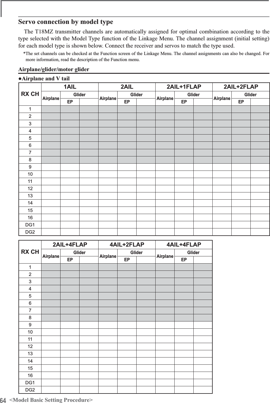
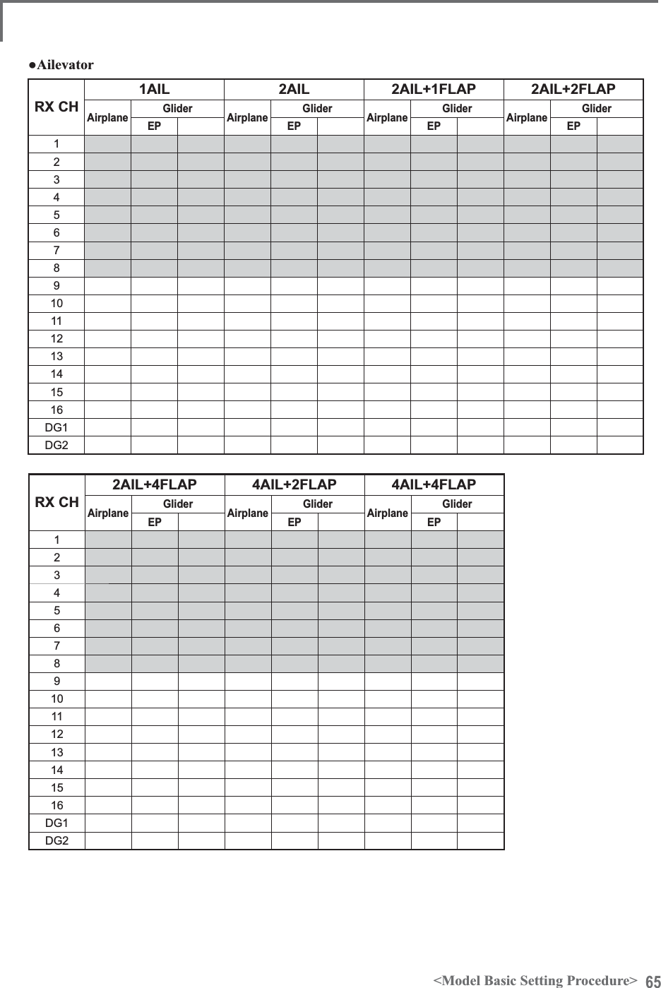
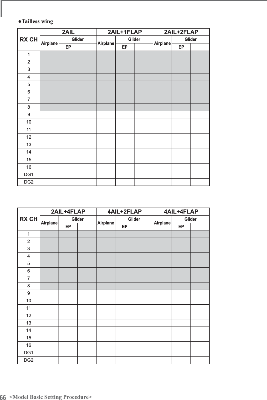
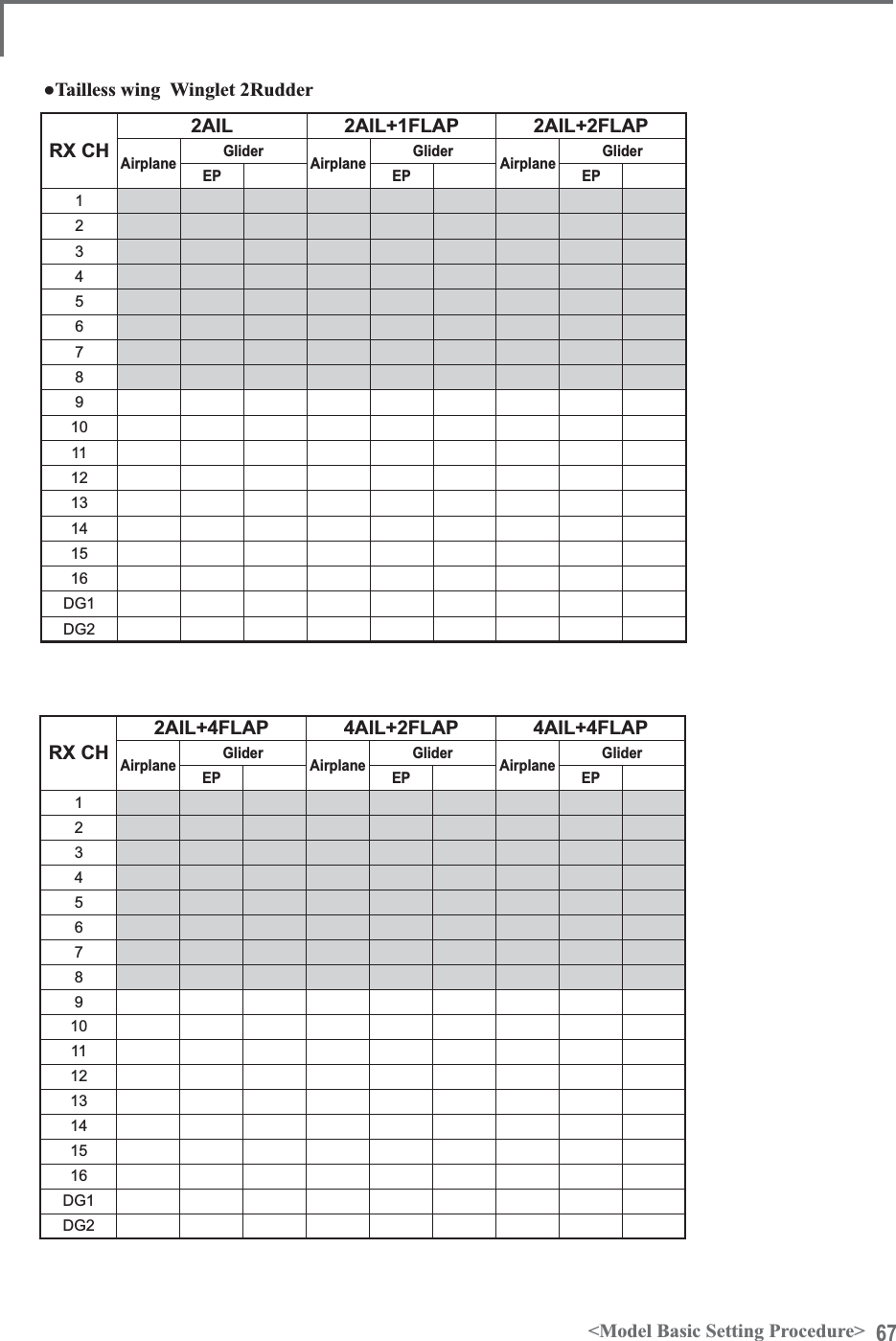
![60 <Model Basic Setting Procedure>ŏ6ZDVKSODWHFRUUHFWLRQ([FHSW+PRGH2SHUDWLRQRIWKHVZDVKSODWHQHDUWKHKRYHULQJSRLQWFDQEHFRUUHFWHGE\VZDVK$)5IXQFWLRQFRUUHFWLRQPL[LQJ8VHWKLVZKHQSLWFKDLOHURQDQGHOHYDWRURSHUDWLRQFDXVHVWKHVZDVKSODWHWRGHYLDWHIURPWKHQRUPDOGLUHFWLRQ&DOOWKH6ZDVKVHWXSĺ6ZDVKGHWDLOVVFUHHQ3LWFKVORZVLGHDQGKLJKVLGHOLQNDJHFRUUHFWLRQLVDOVRSRVVLEOH$GMXVWVRWKDWSLWFKRSHUDWLRQFDXVHVWKHVZDVKSODWHWRPRYHXSDQGGRZQLQWKHKRUL]RQWDOVWDWH5. Throttle curve settingThis function adjusts the pitch operation curve in relation to the movement of the throttle stick for each condition.(17 points curve)The pitch curve can be freely selected from linear operation curve to smooth curve, and adjusted tomatch the curve you want by means of the T18MZ’spowerful Curve Edit Function (6 types of curves can be selected). Up to 17 points can be set for linear RUFXUYHW\SHV+RZHYHUZKHQXVLQJWKHSRLQWVRUSRLQWVVSHFL¿HGWRFUHDWHDFXUYHDVLPSOHDQGsmooth curve can be created by selecting the curvetype and reducing the number of input points to 3or 5, and then entering the specified value at the corresponding points that you created.6HWWLQJH[DPSOH!Call the throttle curve of each condition with the condition select switch.ŏ1RUPDOFXUYHDGMXVWPHQW1RUPDOFXUYHXVHV1RUPDO/LQHDUW\SHDQGFUHDWHVDEDVLFSLWFKFXUYHFHQWHUHGQHDUKRYHULQJ7KLVFXUYHLVDGMXVWHGWRJHWKHUZLWKWKH7KURWWOH&XUYH1RUPDOVRWKDWWKHHQJLQHVSHHGLVFRQVWDQWDQGXSGRZQFRQWUROLVHDVLHVWŏ,GOHXSFXUYHDGMXVWPHQW7KHKLJKVLGHSLWFKFXUYHVHWVWKHPD[LPXPSLWFKUHJDUGOHVVRIWKHHQJLQHORDG7KHORZVLGHSLWFKFXUYHFUHDWHVDFXUYHPDWFKHGIRUDHUREDWLFVORRSUROO'HWF1RWH:KHQWKHFXUYHW\SHLVFKDQJHGWKHGDWDLVUHVHW4. Fuselage linkageConnect the throttle rudder, ailerons, elevators, pitch, and other rudder linkages in accordance with the kit instruction manual. For a description of the connection method, see "Receiver and Servos Connection".7KHFKDQQHODVVLJQPHQWRIWKH70=LVGLIIHUHQWIURPWKDWRIRXUH[LVWLQJV\VWHPV7KHchannel assigned to each function can be checked DWWKH)XQFWLRQPHQXRIWKH/LQNDJH0HQXŏ:KHQWKHGLUHFWLRQRIRSHUDWLRQRIWKHOLQNDJHLVUHYHUVHXVHWKH5HYHUVHIXQFWLRQRIWKH/LQNDJH0HQX$OVRXVHWKHVZDVK$)5IXQFWLRQLQRWKHUWKDQWKH+PRGHŏ$GMXVWWKHGLUHFWLRQRIRSHUDWLRQRIWKHJ\UR*\URVLGHIXQFWLRQŏ&RQQHFWWKHWKURWWOHOLQNDJHVRWKDWWKHFDUEXUHWRUEHFRPHVIXOORSHQDWIXOOWULPWKURWWOHFXWLVSRVVLEOHŏ%DVLFDOO\DGMXVWWKHQHXWUDOSRVLWLRQDQGUXGGHUDQJOHDWWKHOLQNDJHVLGHDQGILQHWXQHZLWKWKH6XE7ULPIXQFWLRQDQG(QG3RLQWIXQFWLRQUXGGHUDQJOHDGMXVWPHQW7RSURWHFWWKHOLQNDJHDOLPLWSRVLWLRQFDQDOVREHVHWZLWKWKH(QG3RLQWIXQFWLRQ](https://usermanual.wiki/Futaba/T18MZ-24G.User-manual-2-Page-31-100/User-Guide-1596898-Page-30.png)
![61<Model Basic Setting Procedure>&RQÀUPWKDWWKHUDWHRIWKHVORZHVWSRVLWLRQRIWKHVWLFNLVLQLWLDOVHWWLQJ%HVXUHWKDWZKHQVHWWRKLJKVLGHWKHFXUYHRIDQ\FRQGLWLRQGRHVQRWH[FHHGExample of pitch curve setting:&DOOWKHSLWFKFXUYHRIHDFKFRQGLWLRQZLWKWKHFRQGLWLRQVHOHFWVZLWFK*Pitch curve graph display can be switched to pitch angle direct reading display.$3LWFKFXUYH1RUPDO0DNHWKHSLWFKDWKRYHULQJDSSUR[LPDWHO\º~6º6HWWKHSLWFKDWKRYHULQJZLWKWKHVWLFNSRVLWLRQDWWKHSRLQWDVWKHVWDQGDUG*Stability at hovering may be connected to the throttle curve. Adjustment is easy by using the hovering throttle function and hovering pitch function together.%3LWFKFXUYH,GOHXS7KHLGOHXSSLWFKFXUYHIXQFWLRQFUHDWHVDFXUYHPDWFKHGWRDLUERUQHÁLJKW6HWWRºaºDVVWDQGDUG&3LWFKFXUYH,GOHXS7KHKLJKVLGHSLWFKVHWWLQJLVOHVVWKDQLGOHXS7KHVWDQGDUGLVº'3LWFKFXUYH+ROG$WDXWRURWDWLRQXVHWKHPD[LPXPSLWFKDWERWKWKHKLJKDQGORZVLGHV>3LWFKDQJOHVHWWLQJH[DPSOH@7KURWWOHKROGºaº6. Throttle hold setting&DOOWKH7KURWWOH+ROGIXQFWLRQIURPWKH0RGHOMenu and switch to the throttle hold condition with the condition select switch.1RWH$WLQLWLDOVHWWLQJWKHVHWWLQJPRGHLVWKHJURXSPRGH6LQFHWKLVIXQFWLRQLVQRWXVHGDWRWKHUFRQGLWLRQVVZLWFKWRWKHVLQJOHPRGHEHIRUHVHWWLQJŏ6HWWLQJWRWKHVWDWHZKLFKDFWLYDWHVWKHIXQFWLRQ7KHWKURWWOHKROGIXQFWLRQDOORZVVHWWLQJIRUWKURWWOHFXWDQGVZLWFKLQJRIWKHIXQFWLRQÀ[HGDWWKHLGOHSRVLWLRQE\VZLWFKIRUWUDLQLQJ(LWKHURQHRUERWKIXQFWLRQVFDQEHSHUIRUPHGŏ+ROGSRVLWLRQVHWWLQJ7KLVIXQFWLRQVHWVWKHVHUYRRSHUDWLRQSRVLWLRQDWWKURWWOHKROG7KURWWOHFXWDQGLGOHSRVLWLRQVŏ2WKHUVHWWLQJV:KHQ\RXZDQWWROLQNRSHUDWLRQZLWKVWLFNPDQLSXODWLRQWKH$XWRPRGHFDQEHVHW:KHQ\RXZDQWWRDGMXVWWKHVHUYRVSHHGDGMXVW>6SHHG@3LWFKWR58'PL[LQJVHWWLQJUse this function when you want to suppressthe torque generated by the changes in the pitch and speed of the main rotor during pitch operation. Adjust it so that the nose does not swing in the UXGGHUGLUHFWLRQ+RZHYHUZKHQXVLQJDKHDGLQJhold gyro like those shown below, do not use Pitch to RUD mixing.1RWH:KHQXVLQJD*<*<*<*<RURWKHUKHDGLQJKROGJ\URWKLV3LWFKWR58'PL[LQJVKRXOGQRWEHXVHG7KHUHDFWLRQWRUTXHLVFRUUHFWHGDWWKHJ\URVLGH:KHQRSHUDWLQJWKHJ\URLQWKH$9&6PRGHWKHPL[HGVLJQDOZLOOFDXVHQHXWUDOGHYLDWLRQV\PSWRPVDQGWKHJ\URZLOOQRWRSHUDWHQRUPDOO\Call the Pitch to RUD mixing function from the Model Menu, and set the curve for each condition. $WLQLWLDOVHWWLQJWKLVIXQFWLRQLVLQWKH,1+VWDWH7RXVHLWVHWLWWRWKH21VWDWH(17 points curve)Curve setting of up to 17 points is possible. +RZHYHULQWKHIROORZLQJVHWWLQJH[DPSOHDsimple curve can be adjusted by using the [Linear] curve type.1RWH$WLQLWLDOVHWWLQJWKHVHWWLQJPRGHLVWKHJURXSPRGH,QWKLVPRGHWKHVDPHFRQWHQWVDUHVHWDWLQDOOFRQGLWLRQV:KHQ\RXZDQWWRVHWWKHVHOHFWHGFRQGLWLRQRQO\VZLWFKWRWKHVLQJOHPRGH6HWWLQJH[DPSOH!Call the mixing curve of each condition with the condition select switch.ŏ7KURWWOHKROGFXUYHDGMXVWPHQW7KHWKURWWOHKROGFXUYHLVXVHGZKHQSHUIRUPLQJDXWRURWDWLRQGLYHV](https://usermanual.wiki/Futaba/T18MZ-24G.User-manual-2-Page-31-100/User-Guide-1596898-Page-31.png)
![62 <Model Basic Setting Procedure>$FXUYHVHWWLQJH[DPSOHLVVKRZQEHORZ$3LWFKWR58'PL[LQJFXUYH1RUPDO8VHWKHKRYHULQJV\VWHPDQGVHWWKLVFXUYHWRPDWFKWDNHRIIDQGODQGLQJDQGYHUWLFDOFOLPEDWDFRQVWDQWVSHHG*For this curve, use the initial setting [Linear] curve type and adjust the left and right rates in the [Separate] mode.%3LWFKWR58'PL[LQJ,GOHXS8VHWKLVFXUYHLQºVWDOOWXUQORRSDQGUROOLQJVWDOOWXUQDQGDGMXVWLWVRWKHIXVHODJHLVIDFLQJVWUDLJKWDKHDGZKHQKHDGLQJLQWRWKHZLQG*For this curve, [Linear] curve type can be used and the entirecurve can be lowered with the [Offset] button.&3LWFKWR58'PL[LQJ+ROG7KLVIXQFWLRQLVVHWVRWKDWWKHIXVHODJHLVIDFLQJVWUDLJKWDKHDGDWVWUDLJKWOLQHDXWRURWDWLRQ7KHSLWFKRIWKHWDLOURWRUEHFRPHVQHDUO\º*For this curve, [Linear] curve type can be used and the entirecurve can be lowered with the [Offset] button.ŏ2WKHUVHWWLQJV7KHPL[LQJULVHFKDUDFWHULVWLFDWSLWFKRSHUDWLRQFDQEHDGMXVWHG$QDFFHOHUDWLRQ$&/5IXQFWLRQZKLFKWHPSRUDULO\LQFUHDVHDQGGHFUHDVHWKHPL[LQJDPRXQWFDQEHVHW6ZDVK0L[FRUUHFWVDLOHURQHOHYDWRUDQGpitch interactionThe swash mix function is used to correct the swash plate in the aileron (roll) direction and elevator (cyclic pitch) corresponding to each operation of each condition.7KURWWOHPL[LQJVHWWLQJRPM loss caused by swash operation at aileron or elevator operation can be corrected with the7KURWWOH0L[IXQFWLRQRIWKH0RGHO0HQX+RZclockwise and counterclockwise torque is applied when pirouetting can also be corrected.*\URVHQVLWLYLW\DQGPRGHVZLWFKLQJThe gyro sensitivity and mode switching function is dedicated gyro mixing of the ModelMenu, and can be set for each condition.ŏ1RUPDOFRQGLWLRQKRYHULQJ*\URVHQVLWLYLW\PD[LPXPŏ,GOHXS,GOHXS7KURWWOHKROG*\URVHQVLWLYLW\PLQLPXPŏ+RZHYHUDWDXWRURWDWLRQRIDWDLOGULYHQKHOLFRSWHUWKLVIXQFWLRQPD\QRWKDYHDQ\DIIHFWDWKLJKJ\URVHQVLWLYLW\11. Throttle cut settingThrottle cut provides an easy way to stop the HQJLQHE\ÀLSSLQJDVZLWFKZLWKWKHWKURWWOHVWLFNat idle. The action is not functional at high throttle to avoid accidental dead sticks. The switch’s location and direction must be chosen, as it defaults WR18//*With throttle stick at idle, adjust the cut position until the engine consistently shuts off, but throttle linkage is not binding. When finished, touch the “Throttle Cut” button to exit.2WKHUVSHFLDOPL[LQJVŏ3LWFKWR1HHGOHPL[LQJ7KLVPL[LQJLVXVHGZLWKHQJLQHVZLWKDFRQVWUXFWLRQZKLFKDOORZVQHHGOHFRQWUROGXULQJÁLJKWIXHODLUPL[WXUHDGMXVWPHQW$QHHGOHFXUYHFDQEHVHW7KHQHHGOHVHUYRULVHFKDUDFWHULVWLFVDWWKURWWOHVWLFNDFFHOHUDWLRQGHFHOHUDWLRQRSHUDWLRQFDQEHDGMXVWHG$FFHOHUDWLRQIXQFWLRQŏ)XHOPL[WXUHIXQFWLRQ7KLVPL[LQJLVXVHGLQQHHGOHDGMXVWPHQWRIHQJLQHVZKLFKXVHDIXHOPL[WXUHFRQWUROFDUEXUHWRUŏ*RYHUQRUPL[LQJ7KLVPL[LQJLVGHGLFDWHGJRYHUQRUPL[LQJZKHQDJRYHUQRULVXVHG8SWRUDWHVVSHHGVFDQEHVZLWFKHGIRUHDFKFRQGLWLRQ](https://usermanual.wiki/Futaba/T18MZ-24G.User-manual-2-Page-31-100/User-Guide-1596898-Page-32.png)
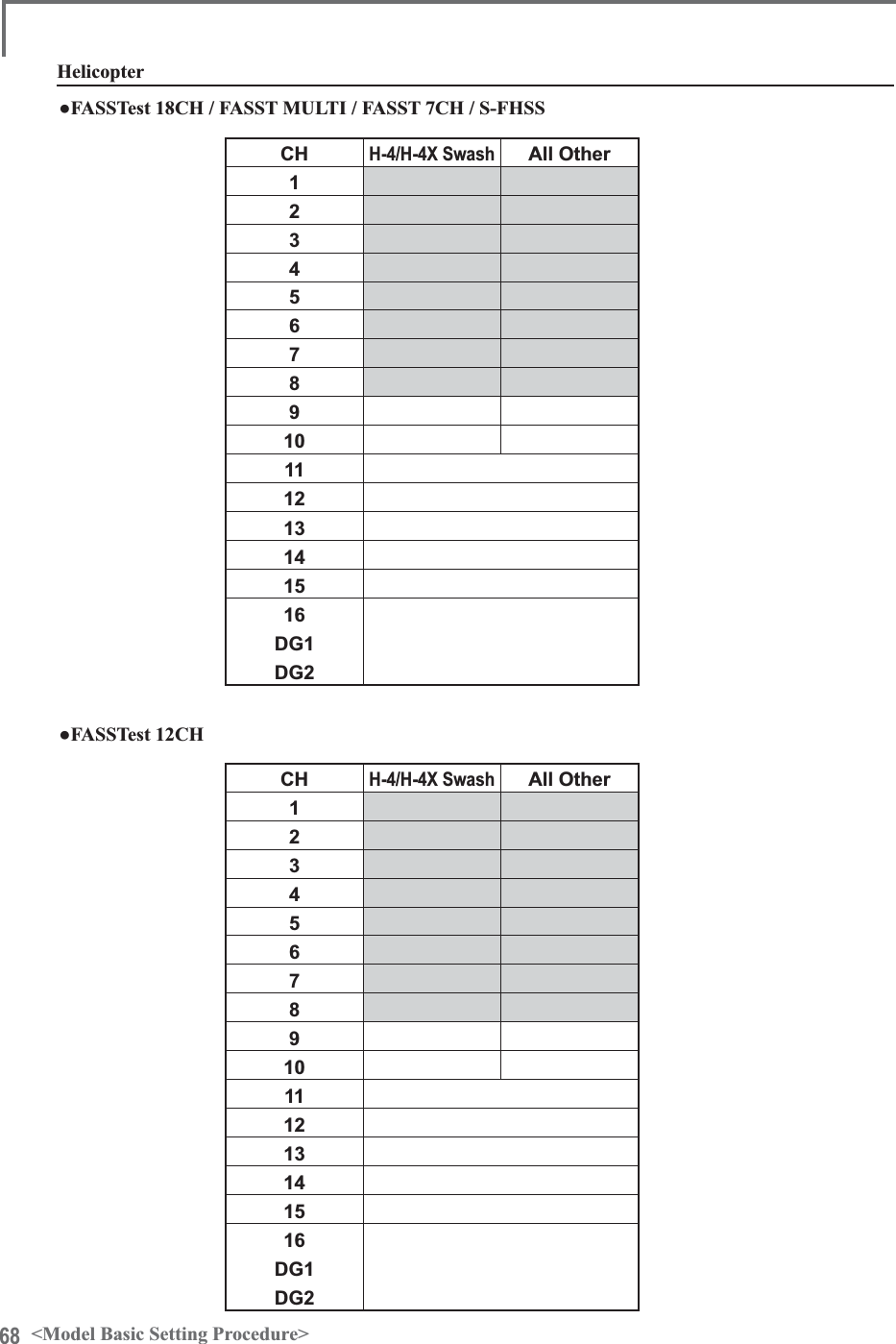
![63<Model Basic Setting Procedure>Receiver switchReceiver batteryCharging port/ DSC connector In S.BUSuse(8/SB)S.BUS notusing it (CH1-8)(7/B)ServosƔ$OZD\VFRQQHFWWKHQHFHVVDU\QXPEHURIVHUYRVƔ7KHUHFHLYHUFKDQQHODVVLJQPHQWGHSHQGVRQWKHPRGHOW\SH6HHWKH6HUYRFRQQHFWLRQE\PRGHOW\SHWDEOHV56%RXWSXWFRQQHFWRUVHFWLRQ5HFHLYHUFRQQHFWRUVƔa2XWSXWIRUFRQYHQWLRQDOV\VWHP&+aƔ%2XWSXWIRUFRQYHQWLRQDOV\VWHP&+3RZHUVXSSO\Ɣ6%2XWSXWIRUFRQYHQWLRQDOV\VWHP&+RU6%86SRUWƔ6%866%86SRUWƔ0RQLWRU/('7HOHPHWU\VHQVRUHWF5HFHLYHUDQGVHUYRVFRQQHFWLRQGLDJUDPReceiver and servos connectionConnect the receiver and servos in accordance with the connection diagram shown below. Always read [Precautions when mounting the receiver and servos] of [Before using]. When mounting the receiver and servos to the fuselage, connect the necessary points in accordance with the kit instruction manual.Ɣ7KH6HUYRFRQQHFWLRQE\PRGHOW\SHWDEOHVDUHVKRZQRQWKHIROORZLQJSDJHVConnect the servos to match the fuselage used.](https://usermanual.wiki/Futaba/T18MZ-24G.User-manual-2-Page-31-100/User-Guide-1596898-Page-33.png)
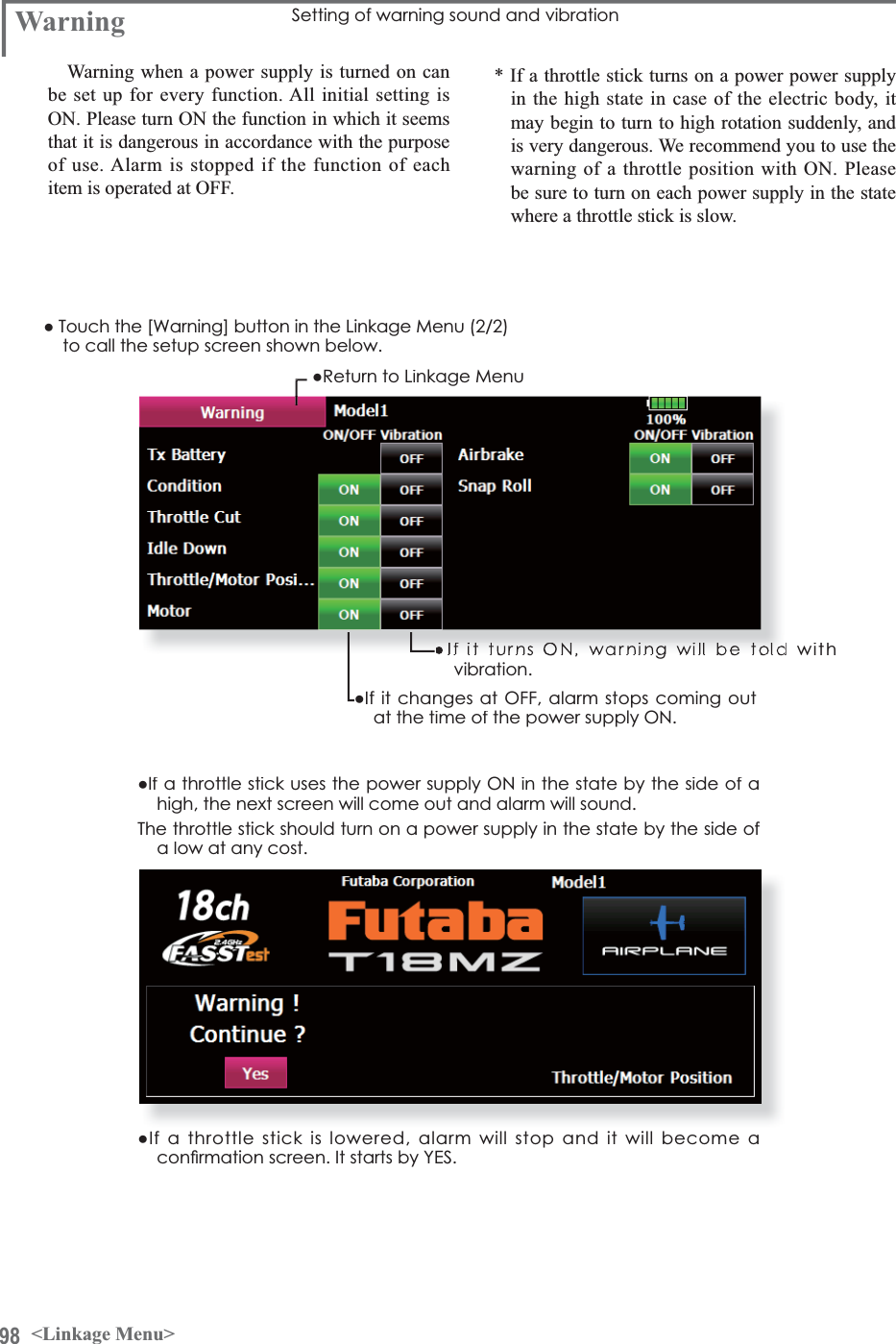
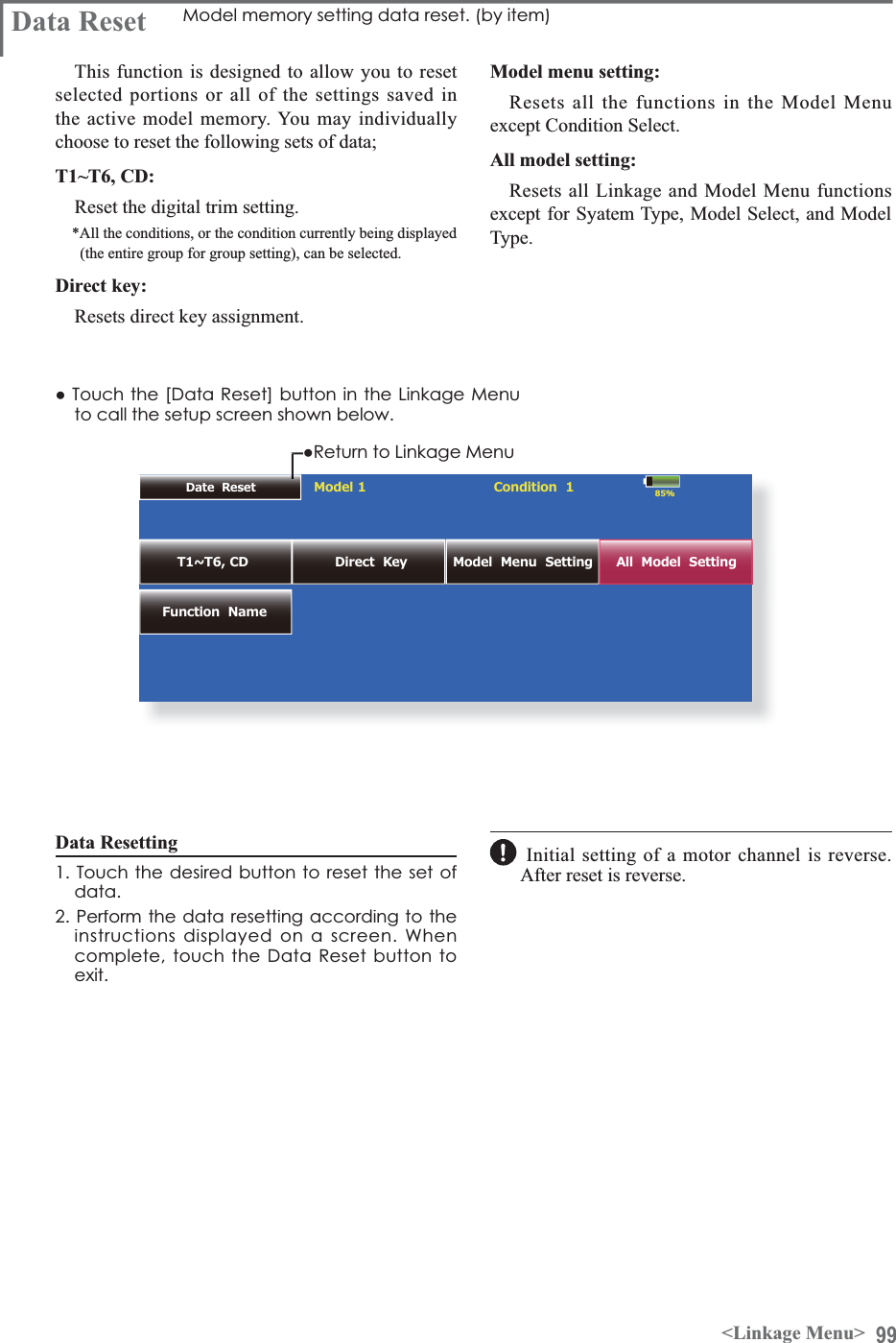
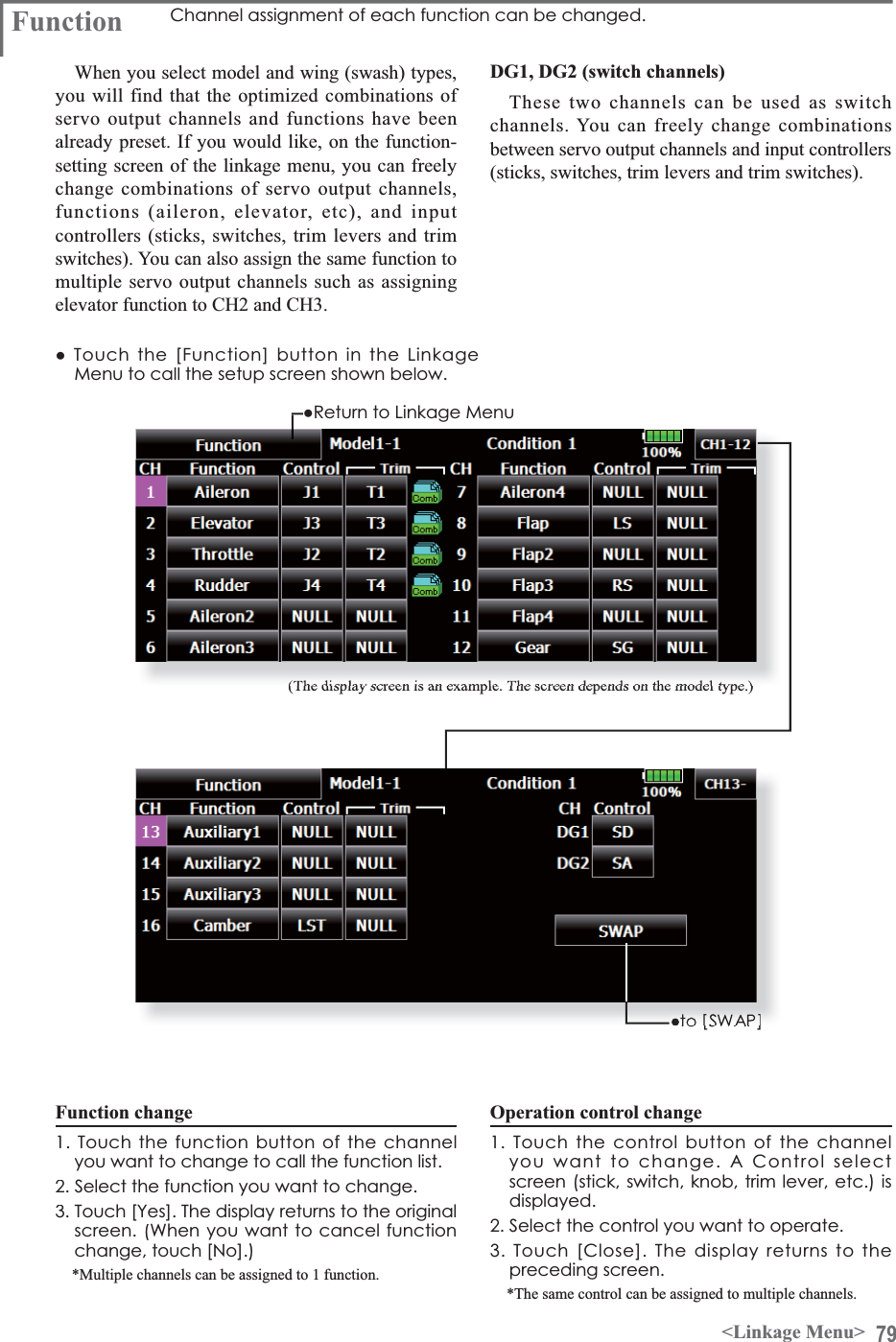
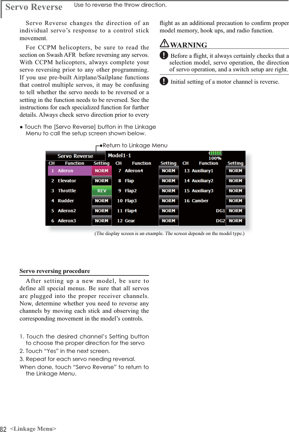
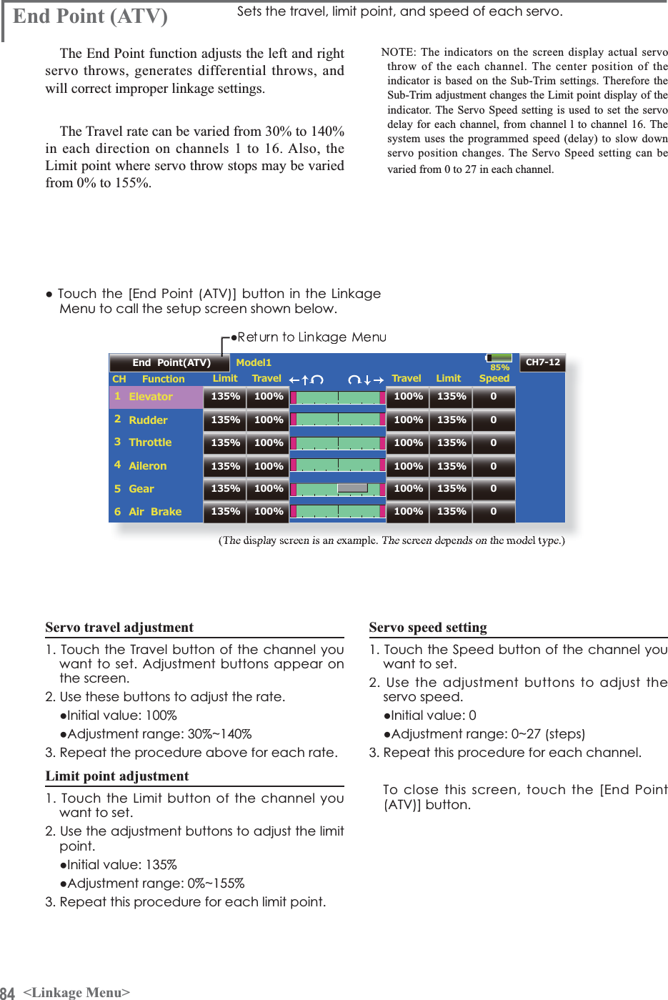
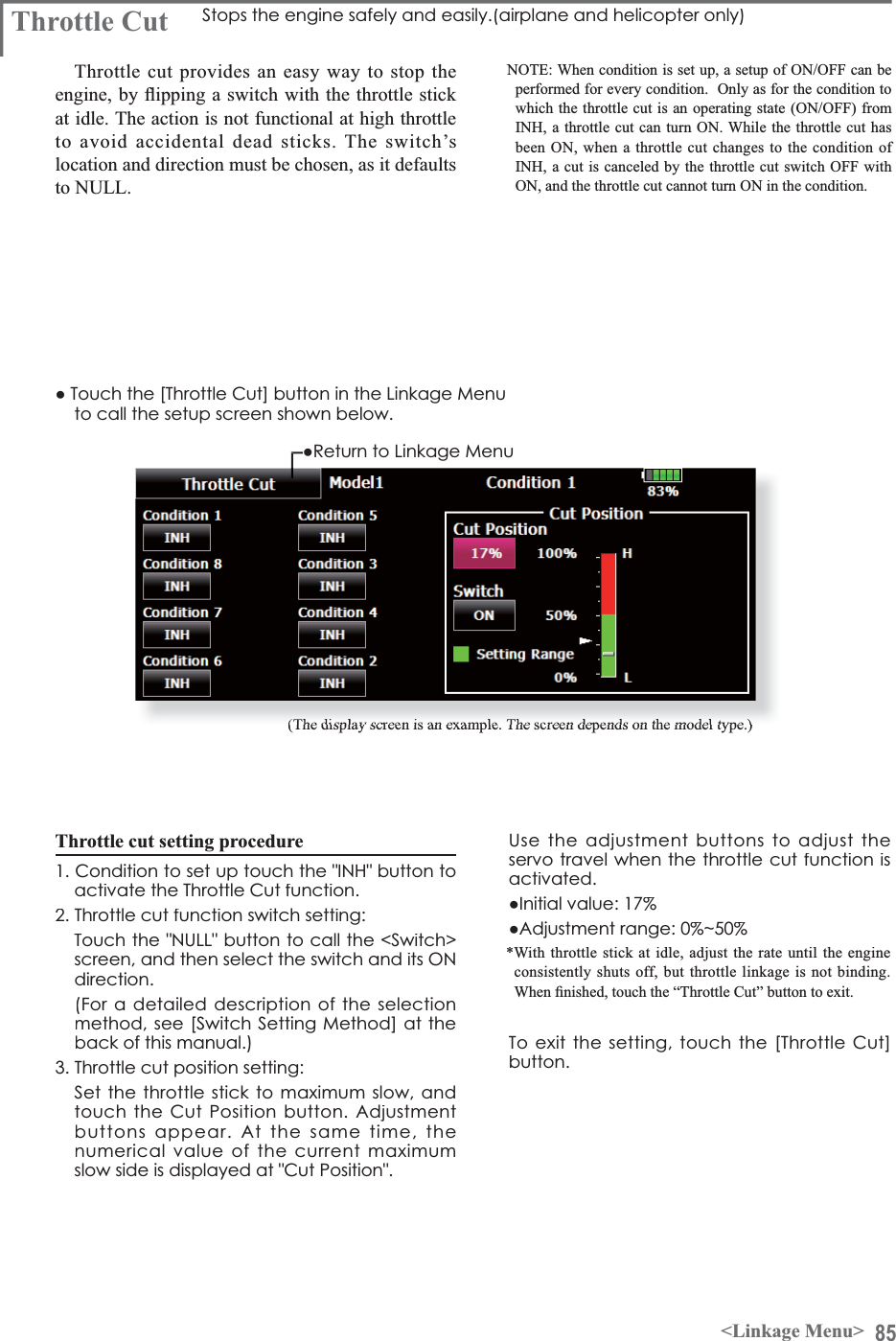
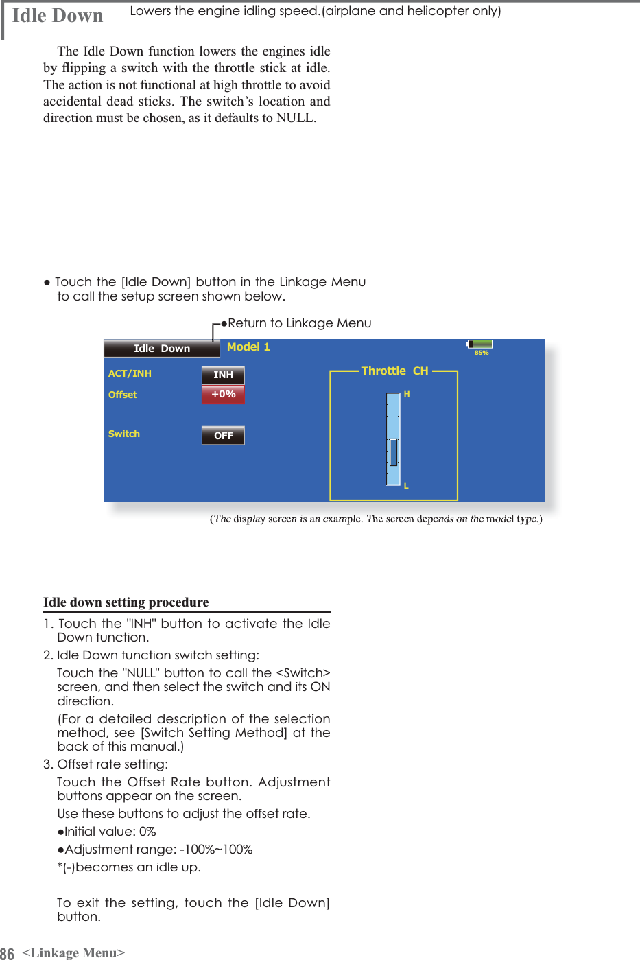
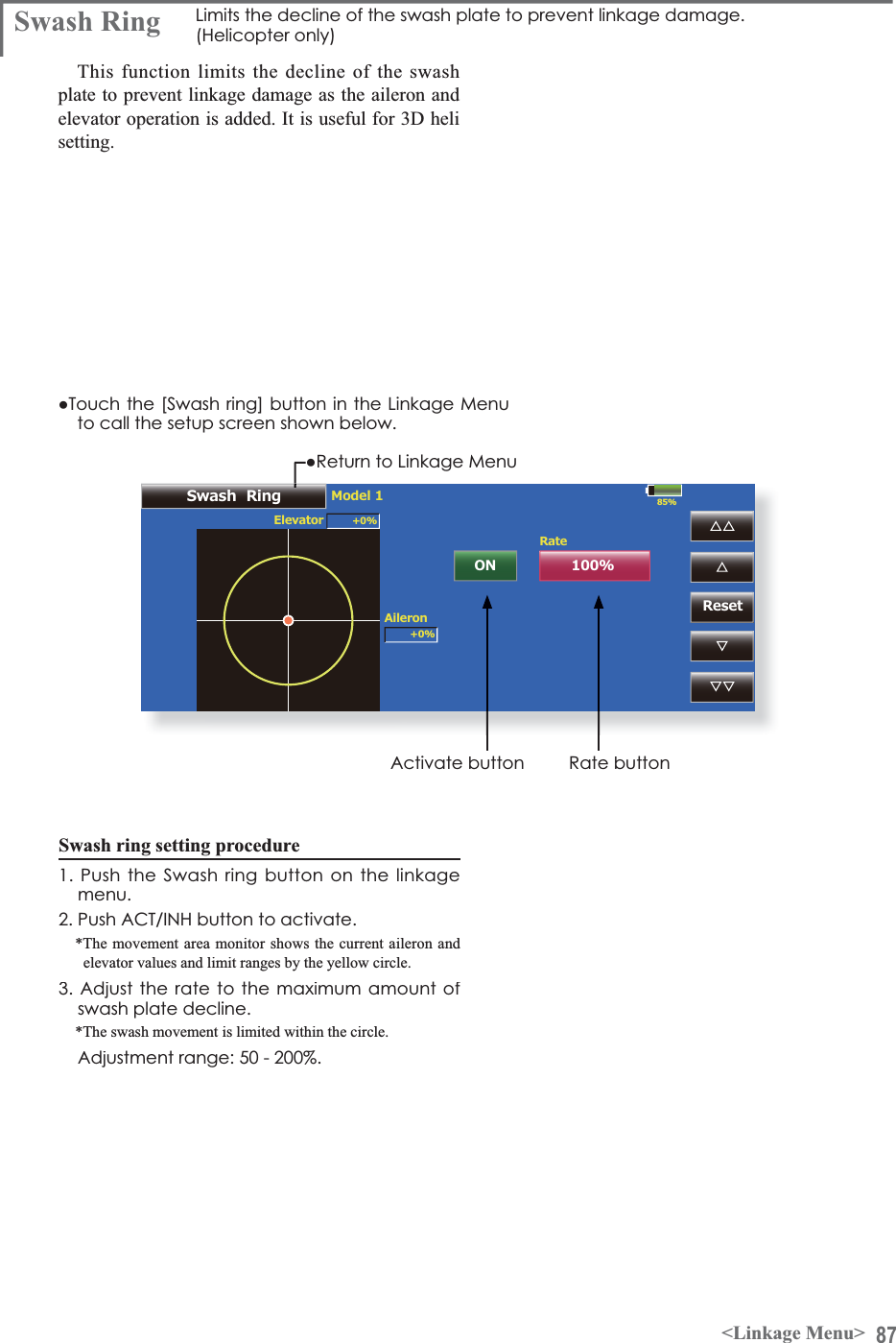
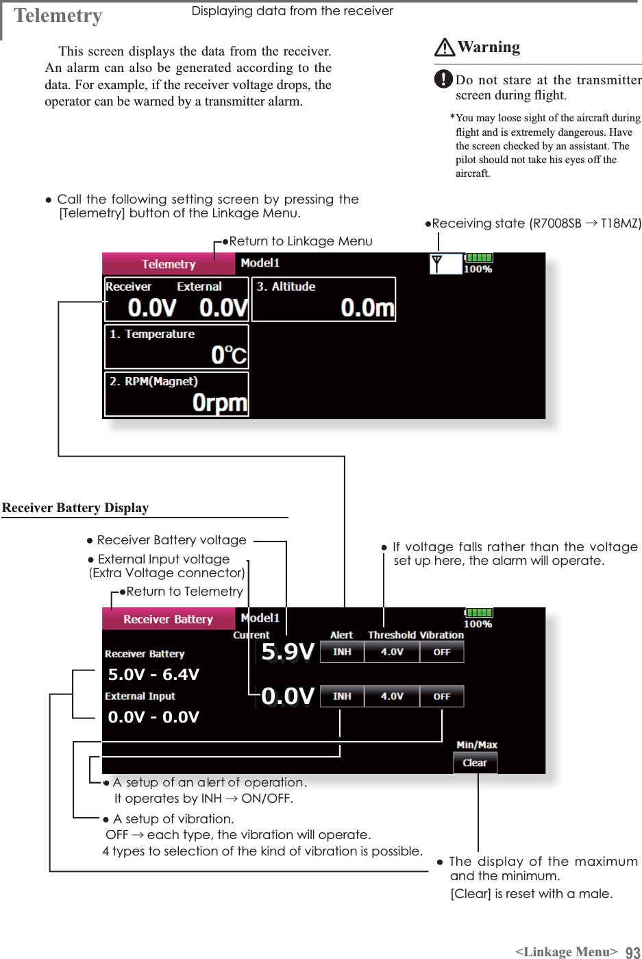
![69<Linkage Menu>FUNCTIONS OF LINKAGE MENUSystem Menu--Condition HoldLinkage Menu Model Menu Cond.HoldModel 1 Normal 85%Linkage MenuModel Select Model Type PictureSystem Type Function Sub-TrimFail Safe Throttle CutTimerSwash Ring SwashSoundServo MonitorServo ReverseIdle DownINHEnd Point(ATV)1/2The Linkage Menu is made up of functions which perform model addition, model type selection, frequency setting, end point setting, and other model basic settings.ŏ5HWXUQWR+RPHVFUHHQŏ:KHQDEXWWRQLQWKH/LQNDJH0HQXRIWKH+RPHVFUHHQLVWRXFKHGWKHPHQXVKRZQEHORZLVFDOOHG7RXFKWKHEXWWRQRIWKHIXQFWLRQ\RXZDQWWRVHWThe functions which can be selected depend on the model type. A typical menu screen is shown below.Linkage Menu functions table[Servo Monitor]: Displays the servo test and operation position[Model Select]: Model addition, call, deletion, copy, model name setting[Model Type]: Model type, wing type, switch type, etc. selection[Picture]: Picture paste for each model[Sound]: Sound recording and playback[System Type]: System selection, receiver link[Function]: Channel assignment of each function can be changed[Sub-Trim]: Adjusts the neutral position of each servo[Servo Reverse]: Servo direction reversal[Fail Safe]: Fail safe function and battery fail safe function setting[End Point (ATV)]: Servo basic rudder adjustment and limit setting[Throttle Cut]: Stops the engine safely and easily (airplane and helicopter only)[Idle Down]: Lowers the idle speed of the engine (airplane and helicopter only)[Swash Ring]: Limits the decline of the swash plate to prevent linkage damage (helicopter only)[Swash]: Swash AFR and linkage correction function (helicopter only)[Timer]: Timer setting and lap time display[Dial Monitor]: Dial, sliding lever, and digital trim position display[Function Name]: Function Name can be changed[Telemetry]: Displays various data sent from the receiver.[Sensor]: Various telemetry sensors setting[Warning]: Setting of warning sound and vibration[Data Reset]: Model memory set data reset (by item)Condition Hold function ON/OFF button)RUDGHWDLOHGGHVFULSWLRQVHHS&RQGLWLRQ+ROGIXQFWLRQ](https://usermanual.wiki/Futaba/T18MZ-24G.User-manual-2-Page-31-100/User-Guide-1596898-Page-39.png)
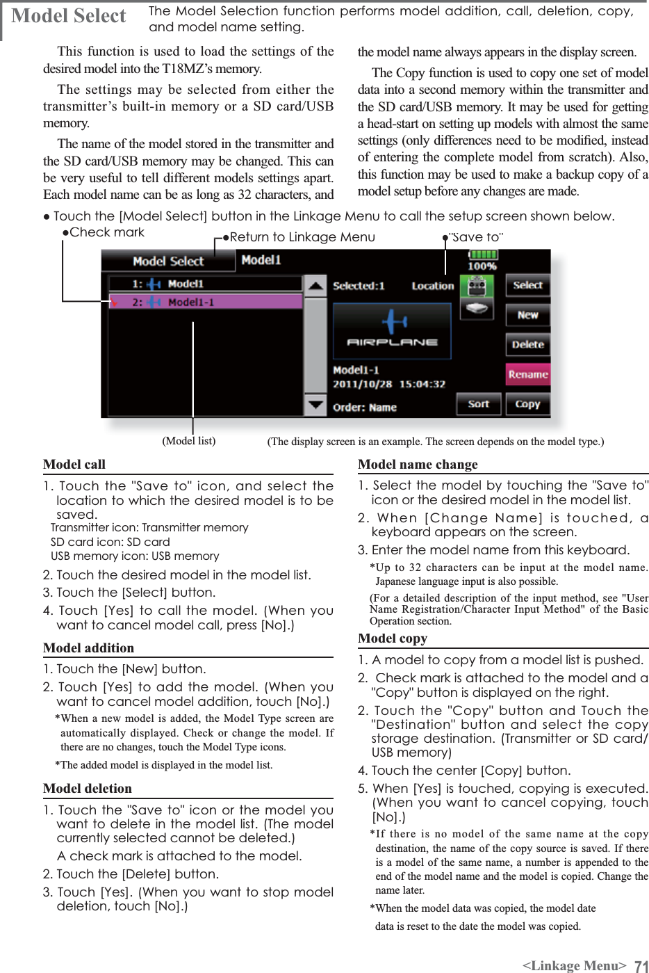
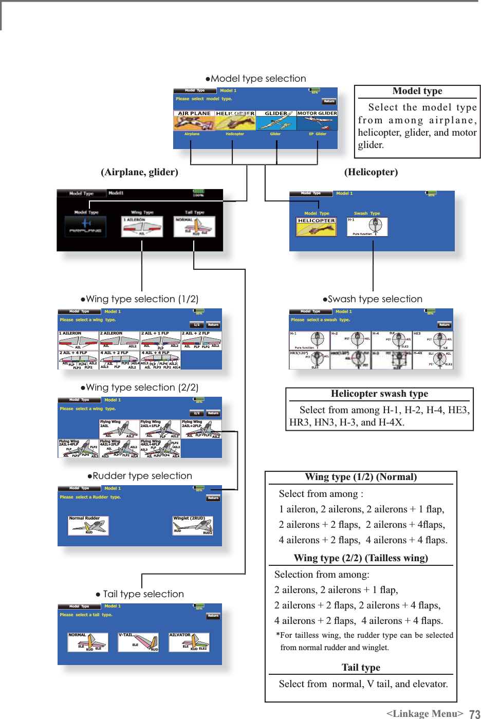
![72 <Linkage Menu>ŏ5HWXUQWR/LQNDJH0HQXŏ7RXFKWKH>0RGHO7\SH@EXWWRQLQWKH/LQNDJH0HQXWRFDOOWKHVHWXSVFUHHQVKRZQEHORZŏ:KHQGDWDWDNLQJRYHULVSRVVLEOHWKHFRQILUPDWLRQVFUHHQRIGDWDLQLWLDOL]DWLRQLVGLVSOD\HG$SXVKRQ>\HV@ZLOOLQLWLDOL]HGDWD$SXVKRQ>QR@ZLOOVXFFHHGGDWDModel Type7KLVIXQFWLRQVHOHFWVWKHPRGHOW\SHIURPDPRQJDLUSODQHKHOLFRSWHUDQGJOLGHU(The display screen is an example. The screen depends on the model type.)Seven types of main wings and three types of tail wings are available for airplanes. Eight swash types are available for helicopters. Seven types of main wings and three types of tail wingsare available for gliders. Functions and mixing functions necessary for each model type are set in advance at the factory.1RWH7KH0RGHO7\SHIXQFWLRQDXWRPDWLFDOO\VHOHFWVWKHDSSURSULDWHRXWSXWFKDQQHOVFRQWUROIXQFWLRQVDQGPL[LQJIXQFWLRQVIRUWKHFKRVHQPRGHOW\SH:KHQWKH0RGHO 7\SH6HOHFWLRQFRPPDQGLVDFFHVVHGDOORIWKH GDWDLQWKHDFWLYHPHPRU\LVFOHDUHG%HVXUHWKDW\RXGRQ·WPLQGORVLQJWKLVGDWDRUEDFNLWXS WRDQRWKHUPHPRU\XVLQJWKHFRS\LQJIXQFWLRQVModel type selection&DOOWKH7\SHVHOHFWVFUHHQE\WRXFKLQJWKHPRGHOW\SHZLQJWDLOVZDVKW\SHRURWKHUW\SHEXWWRQ6HOHFWWKHW\SH\RXZDQWWRVHWDQGH[HFXWHW\SHVHOHFWLRQE\WRXFKLQJ><HV@DWWKHFRQILUPDWLRQVFUHHQ:KHQ\RXZDQWWRFDQFHOPRGHOW\SHVHOHFWLRQWRXFK>1R@Data taking over after a swash type change 'DWDWDNLQJRYHUPD\EHSRVVLEOHLQWKHVZDVKW\SHRIDKHOLFRSWHUDWWKHWLPHRIDFKDQJH5HIHUWRWKHIROORZLQJWDEOH(YHQZKHQLWVXFFHHGVWKHGDWDRID>VZDVKVHWWLQJ@VFUHHQLVLQLWLDOL]HGBefore After Data taking overH-1, H-2, HE3,HR3, HN3, H-3H-1, H-2, HE3,HR3, HN3, H-3OK++;++;OKH-1, H-2, HE3,HR3, HN3, H-3++;NG++;H-1, H-2, HE3,HR3, HN3, H-3NG](https://usermanual.wiki/Futaba/T18MZ-24G.User-manual-2-Page-31-100/User-Guide-1596898-Page-42.png)
![74 <Linkage Menu>File ListCurrent File File not found !File not found !Model 185%ThumbnailPictureIMG00001Previewŏ7RXFKWKH>3LFWXUH@EXWWRQLQWKH/LQNDJH0HQXWRFDOOWKHVHWXSVFUHHQVKRZQEHORZPicture $SLFWXUHFDQEHSDVWHGIRUHDFKPRGHO6LPSOLILHVLGHQWLILFDWLRQRIWKHPRGHOGDWDGXULQJVFUHHQRSHUDWLRQA photograph of the model taken with a T18MZ camera, digital camera or other file can be pasted as the screen display data for each model. This is convenient in identifying models with the same model name.7KHSLFWXUH¿OHVZKLFKFDQEHGLVSOD\HGRQWKHVFUHHQDUHsize 168 x 80 pixels, file type .bmp (bit map picture)and -3(*¿OHV,ID¿OHODUJHUWKDQWKLVLVSDVWHGWKH,WUHGXFHVof the picture is displayed.When a picture is pasted, it is displayed as the following screen image:ŏ0RGHO6HOHFWVFUHHQŏ+RPHVFUHHQŏ6WDUWXSVFUHHQPasting of picture*Picture data is pasted to the model memory currently in use.*The picture can choose only what is saved in the place (T18MZ, SD card, USB memory) same now as the model data under selection.6HOHFWWKHSLFWXUHIURPWKH7KXPEQDLOE\WRXFKLQJWKHGHVLUHGSLFWXUHGDWD*Before selection, touch the scroll button at the top or bottom of the Thumbnail and confirm the contents of the picture ¿OHVVDYHGDWWKHSUHYLHZVFUHHQ7RSDVWHWKHSLFWXUHWRXFK><HV@:KHQ\RXZDQWWRFDQFHOSDVWLQJWRXFK>1R@[Important]Before reading data from the PC, insert the SD card/USB memory into the transmitter and turn on the power. The following folders areDXWRPDWLFDOO\ZULWWHQ7RUHDGD¿OHIURPWKH3&FRS\WKH¿OHWRDIROGHUE\¿OHW\SHŏ%033LFWXUHÀOHŏ:$9$XGLRÀOHŏ:0$0XVLFÀOHŏ02'(/0RGHOGDWD](https://usermanual.wiki/Futaba/T18MZ-24G.User-manual-2-Page-31-100/User-Guide-1596898-Page-44.png)
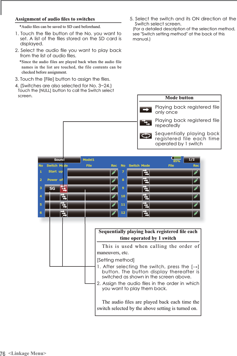
![75<Linkage Menu>85%Sound Model1No Switch ModeStart up3RZHURí23456File Rec 1OFFOFFOFFOFFNo Switch Mode89101112File Rec 7OFFOFFOFFOFFOFFOFF1/285%Model1No Switch ModeStart up01 : test.wav3RZHURí23456File Rec 1OFFOFFOFFOFFEntry CloseRenameDelete<Sound>ŏ5HWXUQWR/LQNDJH0HQXŏ7RXFKWKH>6RXQG@EXWWRQLQWKH/LQNDJH0HQXWRFDOOWKHVHWXSVFUHHQVKRZQEHORZSound 6RXQGUHFRUGLQJDQGSOD\EDFN6DYHGVRXQG¿OH[Important]Before reading data from a PC, insert the SD card/USB memory into the transmitter and turn on the power. The following folders are automatically written. When reading a file from WKH3&FRS\LWWRDKROGHUE\¿OHW\SHŏ%033LFWXUHÀOHŏ:$9$XGLRÀOHŏ:0$0XVLFÀOHŏ02'(/0RGHOGDWDSounds recorded with the microphone built into WKHWUDQVPLWWHUDQGDXGLR¿OHVZDYFDQEHSOD\HGback when the power switch is turned on and off or by preset switch.*Only the voice file saved in the same place (T18MZ, SD card, a USB memory) as the model data under present selection can be chosen.*The recording time from the microphone is up to 3 seconds/UHFRUGLQJ7ZHQW\IRXUDXGLR¿OHVFDQEHVDYHG*The only audio file type which can be recorded is .wav.Only the sounds recorded with the built-in microphone or an DXGLR¿OHVDYHGIURP\RXU3&WRWKHGDWDSDFNFDQEHSOD\HGback.6HWXSVFUHHQV1RWRFDQEHLQGLYLGXDOO\assigned to audio file switches, etc. The playback ¿OHVFDQEHVZLWFKHGHDFKWLPHWKHVDPHVZLWFKLVoperated. This can be used when playing back thename of maneuvers, etc.>6RXQGVWDUWLQJ@1R:KHQWUDQVPLWWHUSRZHUVZLWFKWXUQHGRQ1R:KHQWUDQVPLWWHUSRZHUVZLWFKWXUQHGRII1Ra6ZLWFKFDQEHVHWVoice Recording7RXFKDQ\5(&EXWWRQWRFDOOXSWKH6281'5(&25'(5VFUHHQ7RXFKWKH5(&EXWWRQWRVWDUWUHFRUGLQJ5HFRUGLQJWLPHVHFRQGV5HFRUG\RXUYRLFHDV\RXDUHIDFLQJWKHWUDQVPLWWHU·VPLFURSKRQH*Please record to a loud sound.7RILQLVKSUHVV´&/26(µ$OVRVRXQGILOHVFUHDWHGE\\RXU3&PD\EHSOD\HGEDFNE\DVVLJQHGVZLWFKHV)LOHW\SHVZDYÀOHRQO\*A voice file is saved automatically in the same place (amain part, SD card, a USB memory) as the model data XQGHUSUHVHQWVHOHFWLRQDQGD¿OHQDPHLVGLVSOD\HGRQWKH¿OHEXWWRQFRUUHVSRQGLQJWRDUHFRUGLQJEXWWRQ](https://usermanual.wiki/Futaba/T18MZ-24G.User-manual-2-Page-31-100/User-Guide-1596898-Page-45.png)
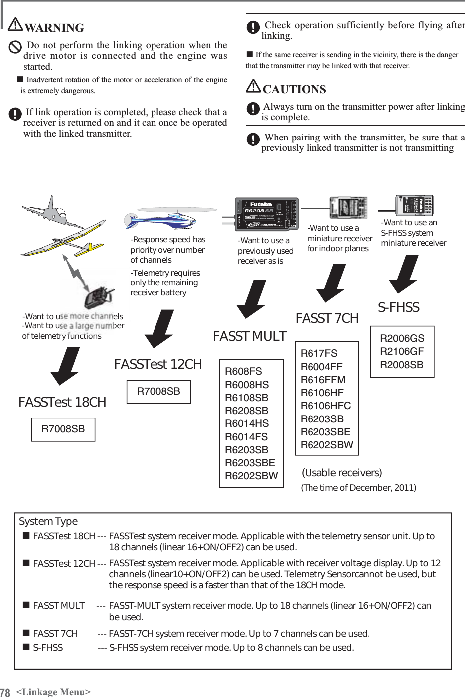
![77<Linkage Menu>System mode selection7KH70=LVIRU*+]RQO\7KHV\VWHPFDQbe selected from among the 5 systems FASSTest 18CH, FASSTest 12CH, FASST MULT, FASST 7CH, S-FHSS. Select the system matched to the type of receiver used.Receiver linkingThe receiver can be controlled without being affected by other transmitters by linking it with the transmitter used. When using a receiver other than that of the purchased set, linking is necessary.Dual receiver function (only FASSTest 18CH mode)Two sets of receivers, and a function which can be linked. Two sets of receivers are recognized individually. For example, in R7008SB, CH output setting function is used, by setting one set as "1-8CH", and setting one more set as "9-16CH", two sets of receivers can be carried in one set of the model, and 1-16CH can be used now. If a Dual receiver function is used, the following function can set up individually.䊶Battery fail-safe voltage setup 䊶Telemetry function ON/OFF䊶Sensor setupTelemetry function (FASSTest mode only)To use the telemetry function, set “Telemetry” to “ON”.D/L Interval (FASSTest mode only)When a telemetry function is enabled, the receiving interval (down-link interval) of sensor data can be changed.ŏ5HWXUQWR/LQNDJH0HQXŏ7RXFKWKH>6\VWHP7\SH@EXWWRQLQWKH/LQNDJH0HQXWRFDOOWKHVHWXSVFUHHQVKRZQEHORZSystem Type6\VWHPPRGHVHWWLQJ5HFHLYHUOLQNIf a D/L interval is enlarged, although renewal of a sensor data display becomes slow, a stick response will improve.Battery fail-safe voltage setup (only FASSTest mode)The voltage which battery fail-safe commits at the WLPHRIDOLQNFDQEHVHWXS9$UHFHLYHUmemorizes at the time of a link.Linking method%ULQJWKHUHFHLYHUWREHOLQNHGWRZLWKLQFPRIWKHWUDQVPLWWHU3UHVVWKH>/LQN@EXWWRQLQWKH>/LQN@ER[RI>6\VWHP7\SH@7KHWUDQVPLWWHUHPLWVDFKLPHVRXQGDQGHQWHUVWKHOLQNPRGH7KHUHFHLYHUSRZHULVLPPHGLDWHO\WXUQHGRQ$ERXWVHFRQGVDIWHUWKHSRZHULVWXUQHGRQWKHUHFHLYHUHQWHUVWKHOLQNZDLWVWDWH5HFHLYHUOLQNZDLWLVDERXWVHFRQG,IOLQNLQJLVVXFFHVVIXOWKHUHFHLYHU/('FKDQJHVIURPUHGWRJUHHQWKHOLQNPRGHHQGVDQGWKHUHFHLYHU,'FRGHLVGLVSOD\HG,IOLQNLQJIDLOVDQHUURUPHVVDJHLVGLVSOD\HG%ULQJWKHWUDQVPLWWHUFORVHUWRWKHUHFHLYHUDQGUHSHDWWKHSURFHGXUHDERYHIURP6WHS*Do not perform the linking operation when the drive motor is connected and the engine was started.* When you use two sets of receivers, please be sure to use it, after performing a setup a "primary" and "secondary" in the "dual" mode. *Since two sets of receivers cannot be individuallyrecognized when the setup a "primary" and "secondary" is not carried out, it becomes impossible to receive telemetry data correctly, and makes it. * The link of two sets of receivers should perform one link operation at a time. If two power supplies of a receiver are switched on simultaneously, it is correctly unreceivable by the transmitter side.* If a dual receiver function is used, in order to receive sensor information by turns from two sets of receivers,renewal of telemetry data becomes slow rather than a single receiver's case.* It cannot link with three sets of receivers.](https://usermanual.wiki/Futaba/T18MZ-24G.User-manual-2-Page-31-100/User-Guide-1596898-Page-47.png)
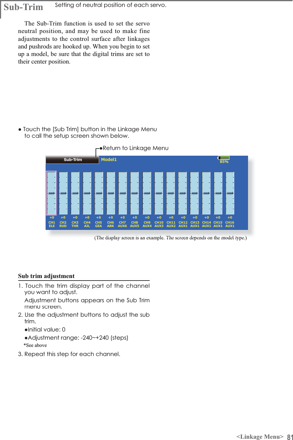
![80 <Linkage Menu>(The display screen is an example. The screen depends on the model type.)Trim change7RXFKWKH7ULPEXWWRQWRFDOOWKH7ULPVHWXSVFUHHQ7KHIROORZLQJLWHPVFDQEHVHWDWWKH7ULPVHWXSVFUHHQŏ+DUGZDUHVHWWLQJ6HOHFWLRQRIVZLWFKHWFZKLFKFRQWUROVWULP7KHVHOHFWVFUHHQLVFDOOHGE\WRXFKLQJWKH>+:6HOHFW@EXWWRQŏ5DWHVHWWLQJŏ2SHUDWLRQVWHSVHWWLQJŏ7ULPPRGHVHWWLQJ1RUPDOPRGH1RUPDOWULPSDUDOOHOVKLIWWULPRSHUDWLRQSWAPIf [SWAP] is pushed, it can become the following screen and can replace two functions with the data set as each channel.7RXFKWKH7ULPEXWWRQWZRFKDQQHOVWRFKDQJHLVSXVKHG,I>2.@LVSXVKHGWZRFKDQQHOVZLOOLQWHUFKDQJH,WFDQFKRRVHRQO\WRWZR$7/PRGH$7/RSHUDWLRQPRGH5HYHUVHLVDOVRSRVVLEOH&750PRGH0D[LPXPFKDQJHQHDUFHQWHUE\FHQWHUWULPRSHUDWLRQŏ6HSDUDWHFRPELQDWLRQPRGH7ULPGDWDDUHVHWWRÁLJKWFRQGLWLRQV6HSDUDWHPRGH7ULPDGMXVWPHQWIRUHDFKÁLJKWFRQGLWLRQ](https://usermanual.wiki/Futaba/T18MZ-24G.User-manual-2-Page-31-100/User-Guide-1596898-Page-50.png)
![83<Linkage Menu>Fail Safe Model1 Batt. F/SReleaseCH Function Function234561GearAir BrakeThrottleAileronElevatorRudder 891011127Auxiliary6Auxiliary5Auxiliary4Auxiliary3Auxiliary2Auxiliary185%ModeHoldOFFOFFB.F/S F/S Posi. CHOFFOFFOFFHold OFFHold OFFHold OFFHold OFFHold OFFModeHoldOFFOFFB.F/S F/S Posi. OFFOFF CH13-OFFOFFHold OFFHold OFFHold OFFHold OFFHold OFFŏ5HWXUQWR/LQNDJH0HQXŏ7RXFKWKH>)DLO6DIH@EXWWRQLQWKH/LQNDJH0HQXWRFDOOWKHVHWXSVFUHHQVKRZQEHORZFail Safe 6HWVWKHVHUYRVRSHUDWLQJSRVLWLRQZKHQWUDQVPLWWHUVLJQDOVFDQQRORQJHUEHUHFHLYHGRUZKHQWKHUHFHLYHUEDWWHU\YROWDJHGURSV(The display screen is an example. The screen depends on the model type.)The Failsafe function may be used to set up positions that the servos move to in the case of radio interference.When the receiver battery voltage drops, the servocan be moved to a preset position. (Battery fail safe function) A battery fail safe function reset switch can be set. (Initial setting: Throttle stick maximum slow side)You may set either of two positions for each channel: Hold, where the servo maintains its last commanded position, or Failsafe, where each servo moves to a predetermined position. You may chooseeither mode for each channel.The T18MZ system also provides you with an advanced battery monitoring function that warns you when the receiver battery has only a little power remaining. In this case, each servo is PRYHGWRWKHGH¿QHGIDLOVDIHSRVLWLRQ7KHEDWWHU\IDLOVDIHPD\EHUHOHDVHGE\RSHUDWLQJDSUHGH¿QHGcontrol on the transmitter (default is throttle), Fail safe setting procedureDecide which channels you want to go to preset positions, and which ones you want to maintain their last commanded position. To select the failsafe mode you wish to set, use the F/S button. This button toggles between the two modes. (Hold, F/S)F/S mode setting:7RXFKWKH)6EXWWRQRIWKHFKDQQHO\RXZDQWWRVHWDQGVHWWKDWFKDQQHOWRWKH>)6@PRGH+ROGWKHFRUUHVSRQGLQJVWLFNFRQWUROVOLGHURURWKHUFRQWUROLQWKHSRVLWLRQ\RXZDQWWKHVHUYRWRPRYHWRZKHQWKHIDLOVDIHIXQFWLRQLVDFWLYDWHGDQGWRXFKWKH)6SRVLWLRQEXWWRQ7KDWSRVLWLRQLVGLVSOD\HGLQSHUFHQWDJH*When you want to return that channel to the Hold mode,touch the [F/S] button again.Battery fail safe setting procedureTo select the B.F/S mode, touch the [B.F/S] button. Each time the button is touched, it toggles do not continue to fly, land as soon as possible.Remember, if the predefined control suddenly moves to a position you did not command, land at once and check your receiver battery.'H¿QHVVHUYRSRVLWLRQZKHQVLJQDOVDUHORVWDQGwhen receiver battery voltage becomes low.WARNINGFor safety, always set the fail safe functions.Ɣ(VSHFLDOO\VHWWKHWKURWWOHFKDQQHOIDLOVDIHIXQFWLRQVRWKDWthe servo moves to the maximum slow side for airplanes and to the slow side from the hovering position for helicopters. Crashing of the model at full high when normal radio waves cannot be received due to interference, etc., is very dangerous.Ɣ,IIDLOVDIHLVUHVHWE\WKURWWOHVWLFNLWPD\EHPLVWDNHQIRUDQengine malfunction and will be reset at throttle slow and the model ZLOOFRQWLQXHWRÀ\,I\RXKDYHDQ\GRXEWVLPPHGLDWHO\ODQGbetween [OFF] and [B.F/S].B.F/S setting:7RXFKWKH>%)6@EXWWRQRIWKHGHVLUHGFKDQQHOWRVHWLWWRWKH%)6PRGH+ROGWKHFRUUHVSRQGLQJVWLFN95VOLGHURURWKHUFRQWUROLQWKHSRVLWLRQ\RXZDQWWKHVHUYRWRPRYHWRZKHQWKHEDWWHU\IDLOVDIHIXQFWLRQLVDFWLYDWHGDQGWRXFKWKH)6SRVLWLRQEXWWRQ7KLVSRVLWLRQLVGLVSOD\HGLQSHUFHQWDJH*When you want to return that channel to OFF, touch the [B.F/S] button again.Battery Failsafe Release FunctionThis function releases the predefined controlfrom it's held position after indicating that your receiver battery is low. (QWHUWKHFRQWUROVHWWLQJVFUHHQE\WRXFKLQJWKH%DWWHU\)65HOHDVHEXWWRQ1RZ\RXPD\FKRRVHWKDWPRYLQJWKHWKURWWOHUHVHWVWKHFRQGLWLRQRUVHOHFWDQRWKHUVWLFNRUVZLWFKGHDFWLYDWHVLW7RVHWDGHVLUHGWKURWWOHUHOHDVHSRVLWLRQPRYHWKHWKURWWOHVWLFNWRWKHSRLQWDWZKLFK\RXZLVKWKH%)6WREHUHOHDVHGŏ7R6ZLWFK!VFUHHQ](https://usermanual.wiki/Futaba/T18MZ-24G.User-manual-2-Page-31-100/User-Guide-1596898-Page-53.png)
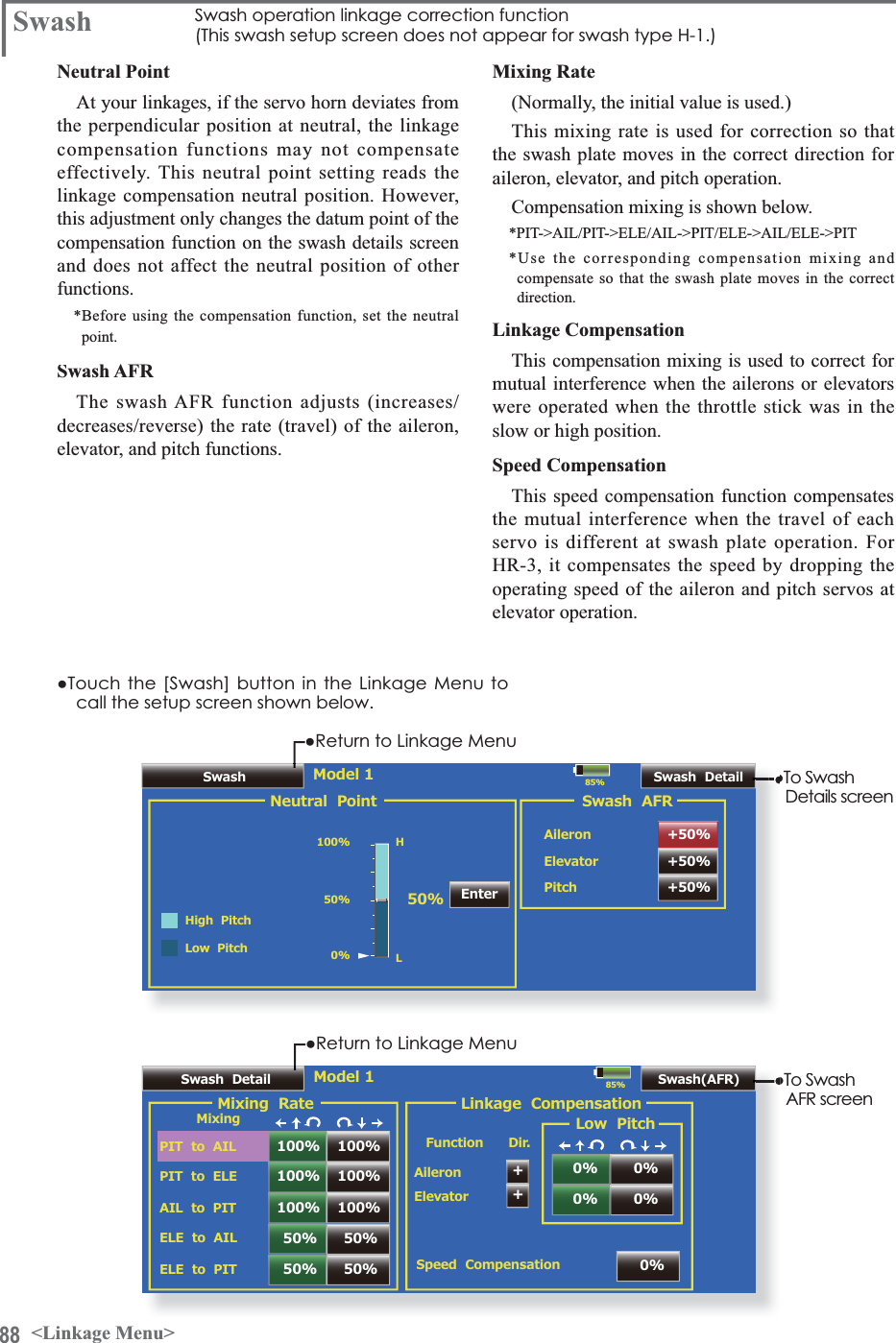
![89<Linkage Menu>Neutral point setting procedure*Becomes the compensation datum point.*Adjusting the servo horn so that the neutral point position is near the 50% position makes the mixing amount small.+ROGWKHVHUYRKRUQDWDULJKWDQJOHWRWKHOLQNDJHURGDQGWKHQWRXFKWKH>(QWHU@EXWWRQDQGUHDGWKHDFWXDOQHXWUDOSRLQW*The neutral point is displayed on the screen. $IWHUUHDGLQJWKLVQHXWUDOSRLQWXVHRWKHUFRPSHQVDWLRQIXQFWLRQVWRPDNHIXUWKHUDGMXVWPHQWV 7RH[LWWKHVHWWLQJWRXFKWKH>6ZDVK@EXWWRQSwash AFR setting procedure $GMXVWVRWKDWWKHVSHFLILHGRSHUDWLRQDPRXQWLVREWDLQHGE\DLOHURQHOHYDWRUDQGSLWFKRSHUDWLRQ7RXFKWKHEXWWRQRIWKH$)5UDWHWREHDGMXVWHG$GMXVWPHQWEXWWRQVDSSHDURQWKHVFUHHQ8VHWKHDGMXVWPHQWEXWWRQVWRDGMXVWWKH$)5UDWH ,QLWLDOYDOXH $GMXVWPHQWUDQJHa 7RH[LWVHWWLQJWRXFKWKH>6ZDVK@EXWWRQMixing rate setting procedure+5LVGHVFULEHGDVDQH[DPSOH7KHPL[LQJDSSOLHGLQRWKHUVZDVKPRGHVLVGLIIHUHQWEXWWKHVHWWLQJSURFHGXUHLVWKHVDPH6HWWKHWKURWWOHVWLFNWRWKHVHWQHXWUDOSRLQW$GMXVWWKHOHQJWKRIWKHOLQNDJHURGVRWKDWWKHVZDVKSODWHLVKRUL]RQWDODWWKLVSRVLWLRQ $OLWWOHDGMXVWPHQWXVLQJVXEWULPVKRXOGEH2.$GMXVWVRWKDWSLWFKRSHUDWLRQZKHQWKHSLWFKFXUYHLVVWUDLJKWLVPD[LPXP$GMXVWWKH$,/!3,7DPRXQWVRWKHUHLVQRLQWHUIHUHQFHLQWKHHOHYDWRURUSLWFKGLUHFWLRQZKHQWKHDLOHURQVWLFNLVPRYHGWRWKHOHIWDQGULJKW$GMXVWWKHOHIWDQGULJKWVLGHVVHSDUDWHO\$GMXVWWKH(/(!$,/DQG(/(!3,7DPRXQWVVRWKHUHLVQRWLQWHUIHUHQFHLQWKHDLOHURQRUSLWFKGLUHFWLRQZKHQWKHHOHYDWRUVWLFNLVPRYHGXSDQGGRZQ$GMXVWWKHXSDQGGRZQVLGHVVHSDUDWHO\$GMXVWWKH3,7!$,/DQG3,7!(/(DPRXQWVVRWKDWWKHVZDVKSODWHLVKRUL]RQWDOZKHQWKHWKURWWOHVWLFNLVVHWWRPD[LPXPVORZDQGIXOOKLJK$GMXVWWKHVORZDQGKLJKVLGHVVHSDUDWHO\7RH[LWVHWWLQJWRXFKWKH>6ZDVK'HWDLOV@EXWWRQLinkage correction setting procedure6HWWKHOLQNDJHFRPSHQVDWLRQDIWHUVHWWLQJWKHPL[LQJUDWH7KLVIXQFWLRQFRPSHQVDWHVIRUHOHYDWRULQWHUIHUHQFHE\DLOHURQRSHUDWLRQRUDLOHURQLQWHUIHUHQFHE\HOHYDWRURSHUDWLRQDW/RZSLWFKDQG+LSLWFKDWFROOHFWLYHSLWFK+5HWFFRQWURO6HWWKHWKURWWOHVWLFNWRWKHPD[LPXPVORZSRVLWLRQ0RYHWKHDLOHURQVWLFNWRWKHOHIWDQGULJKWDQGDGMXVWWKHDLOHURQFRPSHQVDWLRQDPRXQWVRWKDWLQWHUIHUHQFHLQWKHHOHYDWRURUSLWFKGLUHFWLRQDWWKDWWLPHLVPLQLPDO7KHOHIWDQGULJKWVLGHVFDQEHDGMXVWHGVHSDUDWHO\,IWKHLQWHUIHUHQFHLQFUHDVHVZKHQWKHFRPSHQVDWLRQDPRXQWLVLQFUHDVHGPDNHWKHFRPSHQVDWLRQGLUHFWLRQ$GMXVWWKHHOHYDWRUFRPSHQVDWLRQDPRXQWVRWKDWWKHLQWHUIHUHQFHLQWKHDLOHURQRUSLWFKGLUHFWLRQZKHQWKHHOHYDWRUVWLFNZDVPRYHGXSDQGGRZQLVPLQLPDO3HUIRUPDLOHURQDQGHOHYDWRUFRPSHQVDWLRQVLPLODUO\IRUWKHWKURWWOHVWLFNIXOOKLJKVLGH7RH[LWVHWWLQJWRXFKWKH>6ZDVK'HWDLOV@EXWWRQSpeed compensation setting procedure6HWWKHWKURWWOHVWLFNWRWKHQHXWUDOSRLQWSRVLWLRQ0RYHWKHHOHYDWRUVWLFNTXLFNO\DQGDGMXVWWKHVSHHGFRPSHQVDWLRQDPRXQWVRWKDWWKHLQWHUIHUHQFHLQWKHSLWFKGLUHFWLRQLVPLQLPDO7RH[LWVHWWLQJWRXFKWKH>6ZDVK'HWDLOV@EXWWRQNotes: ,IWKHOLQNDJHVWLFNVRXWRULVVWUHWFKHGWLJKWFRUUHFWFRPSHQVDWLRQZLOOQRWEHDSSOLHG3HUIRUPFRUUHFWLRQZLWKVXUSOXVOLQNDJH 7KHSLWFKDQJOHFKDQJHVDIWHUDGMXVWPHQW5HVHWWKHSLWFKDQJOHZKHQDFWXDOO\IO\LQJDIWHUFRPSHQVDWLRQSURFHVVLQJ](https://usermanual.wiki/Futaba/T18MZ-24G.User-manual-2-Page-31-100/User-Guide-1596898-Page-59.png)
![92 <Linkage Menu>Please select a function.85%Function NameAileron Elevator Throttle Rudder Gear Flap Aileron2 Aileron3Aileron4 Elevator2 Flap2 Air Brake Fuel-Mix Gyro Gyro2 Gyro3Throttle2 Throttle3 Throttle4 Flap3 Flap4 Rudder2 CamberMotor Auxiliary7 Auxiliary6 Auxiliary5 Auxiliary4 Auxiliary3 Auxiliary2 Auxiliary1Please select a function.85%Function NameAileron Elevator Throttle Rudder Gear Flap Aileron2 Aileron3Aileron4 Elevator2 Flap2 Air Brake Fuel-Mix Gyro Gyro2 Gyro3Throttle2 Throttle3 Throttle4 Flap3 Flap4 Rudder2 CamberMotor Auxiliary7 Auxiliary6 Auxiliary5 Auxiliary4 Auxiliary3 Auxiliary2 Auxiliary1CloseRenameResetRenameReset10 CharactersAileronCurrentAileronDefaultAILCurrentAILDefault4 Charactersŏ7RXFKWKH>)XQFWLRQ1DPH@EXWWRQLQWKH/LQNDJH0HQXWRFDOOWKHVHWXSVFUHHQVKRZQEHORZFunction Name )XQFWLRQ1DPHFDQEHFKDQJHGThe setup screen can display functions names of upWRFKDUDFWHUVDQGXSWRFKDUDFWHUVProcedure for changing the functions nameSelect [Function Name] from the Linkage Menu.Select the function whose name you want tochange.Press the [Change name] button and enter the name in 10 characters and 4 characterseach from the displayed keyboard. After the characters are entered, press the keyboard [Return] key When the [Reset] key is pressed, the functionname is reset its original name.](https://usermanual.wiki/Futaba/T18MZ-24G.User-manual-2-Page-31-100/User-Guide-1596898-Page-62.png)
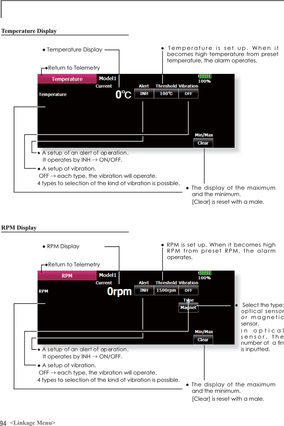
![95<Linkage Menu>Altitude Display ŏ$OWLWXGHLVVHWXS:KHQLWEHFRPHVKLJKDOWLWXGHIURPSUHVHWDOWLWXGHWKHDODUPRSHUDWHVŏ$OWLWXGH'LVSOD\ŏ$WPRVSKHULFSUHVVXUH'LVSOD\ŏ9DULRPHWHU'LVSOD\+RZPDQ\PHWHUULVHGHVFHQWLQVHFRQGŏ7KHGLVSOD\RIWKHPD[LPXPDQGWKHPLQLPXP>&OHDU@LVUHVHWZLWKDPDOHŏ$VHWXSRIDQDOHUWRIRSHUDWLRQ,WRSHUDWHVE\,1+→212))ŏ$VHWXSRIYLEUDWLRQ2))→HDFKW\SHWKHYLEUDWLRQZLOORSHUDWHW\SHVWRVHOHFWLRQRIWKHNLQGRIYLEUDWLRQLVSRVVLEOHŏ5HWXUQWR7HOHPHWU\Atmospheric pressure is measured by a sensor and an altitude is judged with a difference withground atmospheric pressure. Atmospheric pressure when the power supply of an altitude sensor is set to ON is displayed as a standard (0 m). [Preset] A push on a button will re-set up a standard altitude.What altitude is it?](https://usermanual.wiki/Futaba/T18MZ-24G.User-manual-2-Page-31-100/User-Guide-1596898-Page-65.png)
![96 <Linkage Menu>ŏ5HWXUQWR/LQNDJH0HQXŏ7RXFKWKH>6HQVRU@EXWWRQLQWKH/LQNDJH0HQXWRFDOOWKHVHWXSVFUHHQVKRZQEHORZSensor 9DULRXVWHOHPHWU\VHQVRUVVHWWLQJProcedure for changing the sensor of each slot No.1. Select [Sensor] from the Linkage Menu.2. Select the sensor of the slot No. to be changed.3. Select the type of displayed sensor.4. When the [Yes] key is pressed, the type of sensor is changed.*In the case of the sensor which uses more slots, it may be unable to assign.The telemetry sensor slot No. and which sensor is used at each slot can be changed at this screen.Since the sensor at each slot is determined at initialization and the same slot No. is memorized even for sensors sold separately, sensors can be used by simply connecting them to S.BUS2. When customizing the sensors yourself, perform setting at this screen.[What is a slot?]Servos are classified by CH, but sensors are classified in units called “slot”. There are slots from No. 1 to No. 31.Altitude sensor and other voluminous datasensor units use multiple slots.When 2 or more of the same kind of sensor are used, the sensors themselves must allocate unused slots and memorized the allocated slot.*Three slots of altitude sensor are used. Slot FDQQRWEHXVHGIRUDQDOWLWXGHVHQVRU](https://usermanual.wiki/Futaba/T18MZ-24G.User-manual-2-Page-31-100/User-Guide-1596898-Page-66.png)
![97<Linkage Menu>Procedure for changing the slot No. of each sensor unit1. Select [Sensor] on page 2 of the Linkage Menu.2. Call page 2 by pressing [1/2] and press [Change Slot].3. Connect the receiver battery and the sensor unit to the S.I/F connector behind the rear cover of the transmitter using a 3-way hub or 2-way cord.4. Press the [Read] key. The current slot No. is displayed.5. When a number is pressed, the [ 䂦], [ 䂰], [ 䂦䂦 ] and [ 䂰䂰 ] keys appear. Now change the desired No.6. When the [Write] key is pressed, the desired No. is written to the sensorŏ&DOOWKLVVFUHHQE\VZLWFKLQJWRSDJHE\SUHVVLQJWKH>@EXWWRQRQWKH6HQVRUVFUHHQDQGWKHQSUHVVLQJ>&KDQJH6ORW@ŏ:KHQSUHVVHGWKHFXUUHQWVORW1RLVGLVSOD\HGŏ7KHVORW1RLVZULWWHQWRWKHVHQVRUVRUVFUHHQSensorHUBor Y-adapterReceiver batteryT18MZ](https://usermanual.wiki/Futaba/T18MZ-24G.User-manual-2-Page-31-100/User-Guide-1596898-Page-67.png)