Contents
- 1. User manual-1(page 1-30)
- 2. User manual-2(Page 31-100)
- 3. User manual-3(Page 101-162)
User manual-2(Page 31-100)
31
<Before Use>
S
.BU
S
W
i
r
i
ng example
Battery
Battery
GY520
Extension
cord
Switch
Terminal box
HUB
HUB HUB
HUB HUB
HUB
HUB
ق$QRWKHUSRZHUVXSSO\ك
HUB
ق$QRWKHUSRZHUVXSSO\ك
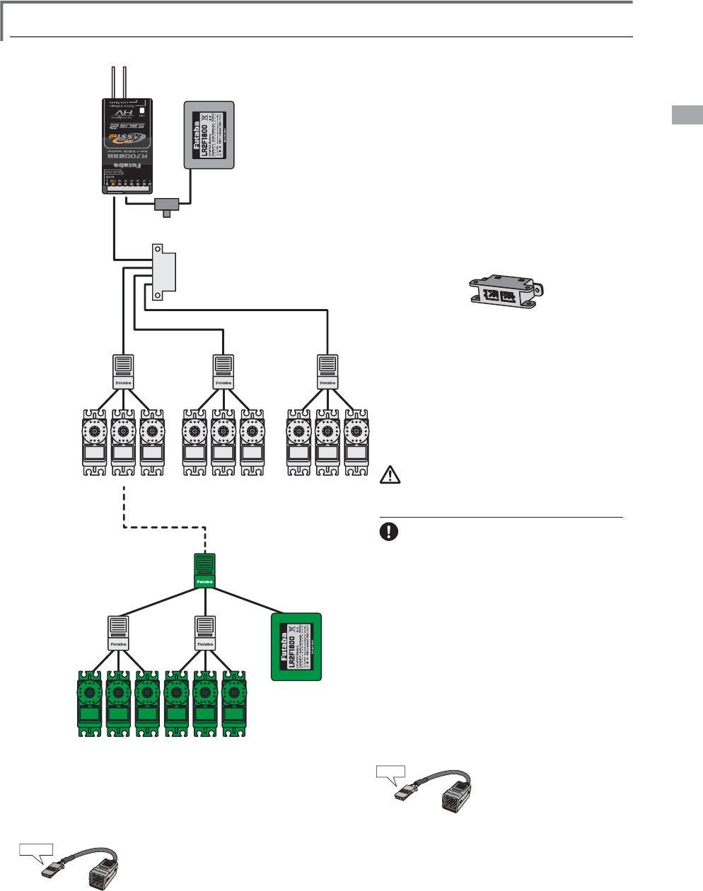
S.BUS Servo
S.BUS Servo
,WRSHUDWHVLQDQRWKHUSRZHU
VXSSO\IRUWKHUHFHLYHU
Receiver
䃂S.BUS Servo
Since the channel number is memorized at
the S.BUS itself beforehand, any connector
can be used. When the SBD-1 sold separately
is used, ordinary servos can be used with the
S.BUS system.
䃂When separate power supply used
When many more servos are used and when
large current servos are used the servos are
driven by a separate power supply by using a
separate power supply 3-way hub.
䃂Terminal box
Four connectors can be inserted
Three connectors can be
inserted.
Used when using a separate
power supply battery.
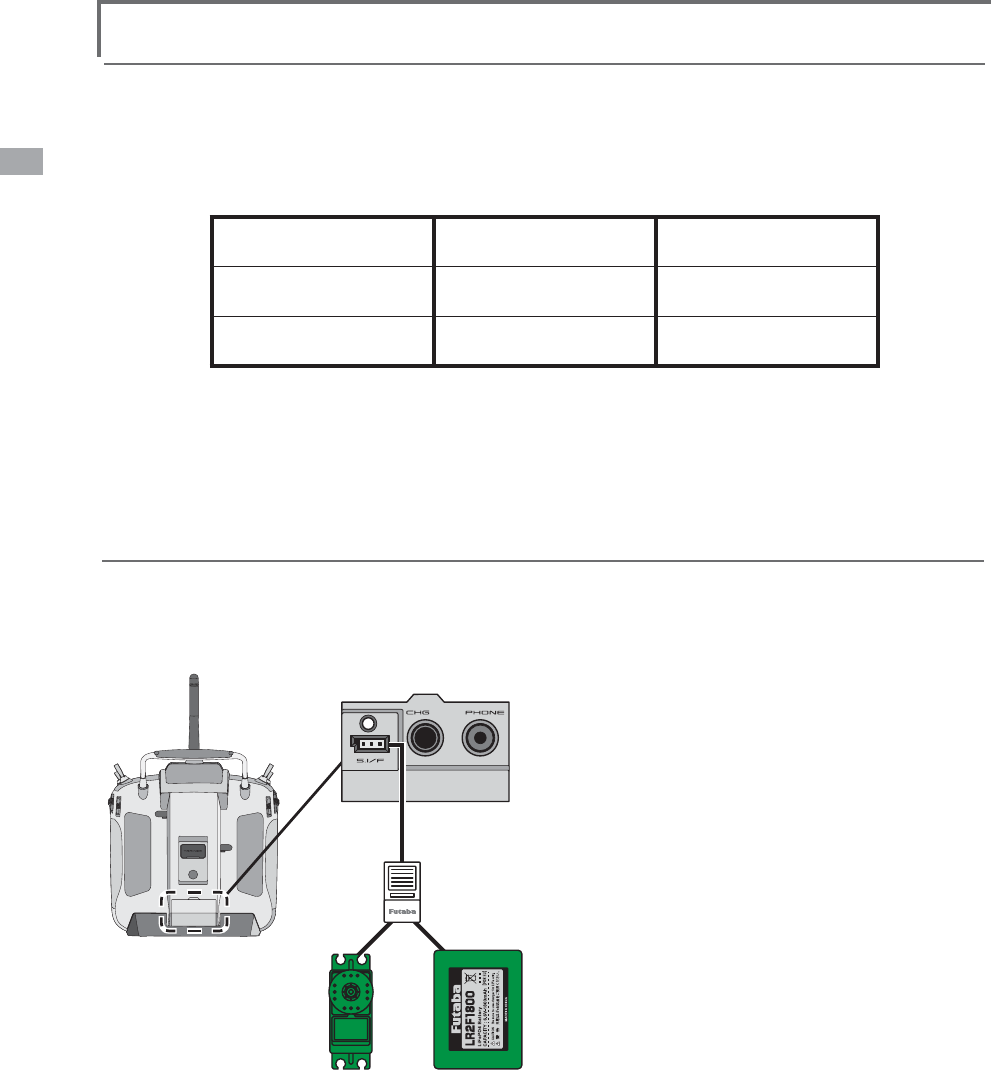
S.BUS
Port
(8/SB)
Orange
Green
Warn
i
ng
Power suppl
y
3
OHDVHXVHDEDWWHU\ZLWKFDSDFLW\RI
e
noug
h
to t
h
e num
b
er an
d
ki
n
d
of servo.
A
d
r
y
b
atter
y
cannot
b
e use
d
.
32 <Before Use>
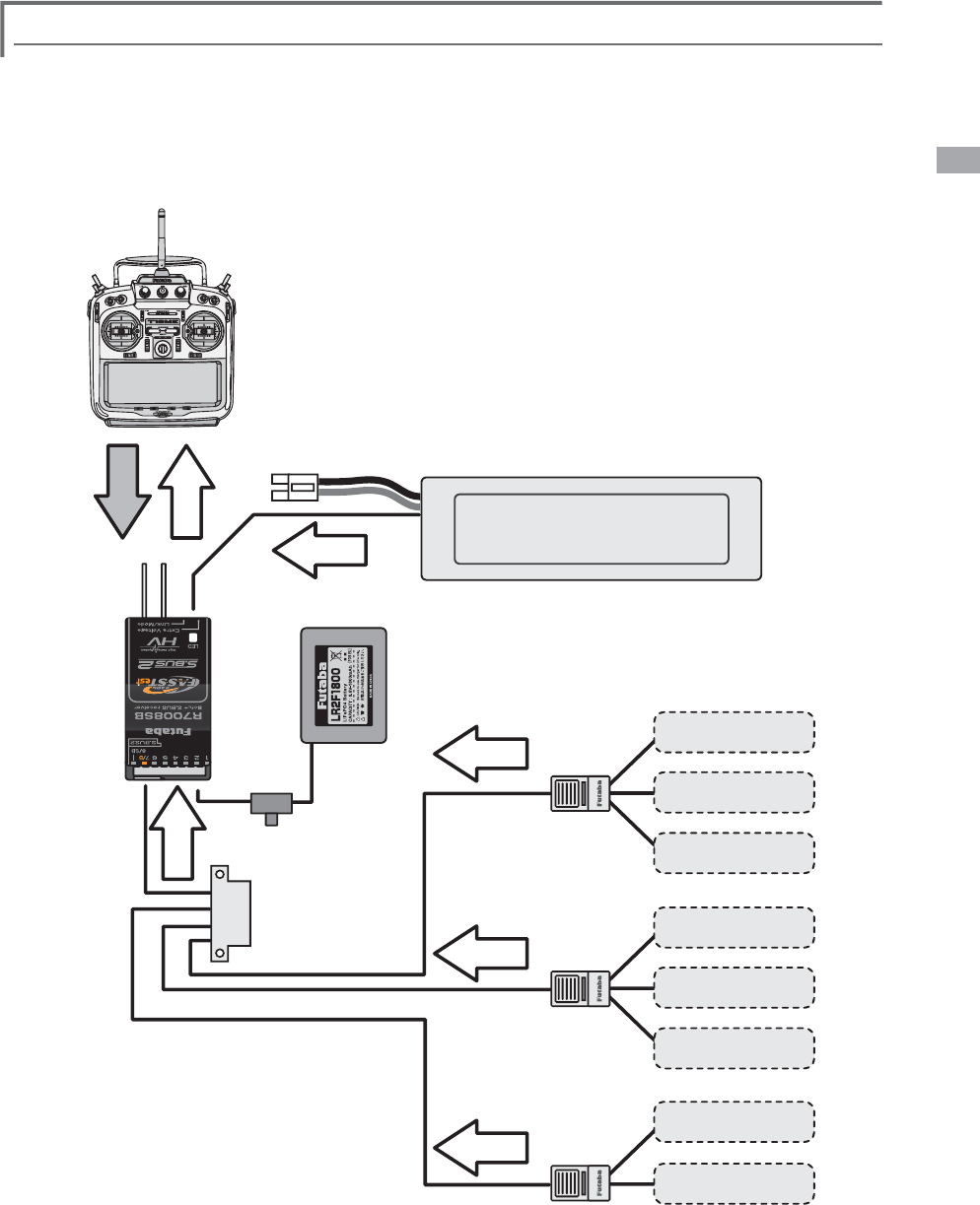
S.BUS2 System
S. BUS2, extend the conventional S.BUS system and support bidirectional communication systems, such as a
telemetry sensor.
Receiver connector S.BUS Servo
S.BUS Gyro telemetry sensor
S.BUS 䂾㬍
S.BUS2 㬍䇭䋨 㶎䋩 䂾
S.BUS device setting
S.BUS servos or a telemetry sensor can be connected to the T18MZ and channel setting (slot setting) and
other settings can be memorized at the S.BUS device.
S.BUS2 TABLE
䋨㶎䋩'RQWFRQQHFW6%866HUYR
S.BUS Gyro to BUS2 connector.
HUB or Y-adaptor
(S.BUS Servo)
S.BUS device
(telemetry sensor)
Receivers
Battery
T18MZ
&RQQHFWWKH6%86GHYLFHDQGEDWWHU\\RX
ZDQWWRVHWZLWKDZD\KXERUZD\FRUG
DVVKRZQLQWKHÀJXUH
7XUQRQWKHWUDQVPLWWHUSRZHU
&DOOWKHVHWXSVFUHHQ
䇭6HUYR6\VWHP0HQX→6%866HUYR
䇭6HQVRU/LQNDJH0HQX→6HQVRU
3HUIRUPVHWWLQJLQDFFRUGDQFHZLWKHDFK
VFUHHQ
7KLVPHPRUL]HVWKHFKDQQHOVORW1RDW
HDFK6%86GHYLFHVRLWFDQEHXVHGE\
FRQQHFWLQJLWWRWKH6%86FRQQHFWRURIWKH
UHFHLYHU
33
<Before Use>
Telemetry
S
ystem
This set is compatible with a telemetry system. Flight status can be displayed at the transmitter by mounting
various sensor units to the fuselage.
*
T
h
e te
l
emetry funct
i
on
i
s app
li
ca
bl
e on
l
y
i
n t
h
e FASSTest 18CH mo
d
e.
(
12CH mo
d
e serves as a
di
sp
l
a y o f
on
ly
Rece
i
ver
b
attet
y
vo
l
ta
g
e an
d
Extra
b
attet
y
vo
l
ta
g
e.
)
*
T
h
e te
l
emetry funct
i
on requ
i
res t
h
e correspon
di
ng rece
i
ver
(
R7008SB
)
.
S.BUS2
Connector
Temperature
Sensor Slot1
Slot2
Slot3
Slot4
Slot5
Slot6
Slot7
Receiver
Battery voltage is
displayed at the transmitter.
Drive battery voltage is
displayed at the transmitter.
Switch
T18MZ
GY520
Extension
cord
Terminal box
HUB
HUB
HUB
Info
Info
Info
Info
Info Info
voltage
Signal
RPM
Sensor
Altitude
Sensor
Altitude
Sensor
Altitude
Sensor
Sensor
Slot8
S.BUS2 Tool
Sensor
䃂Telemetry sensor (sold separately)
Fuselage data can be checked at the transmitter by
connecting various telemetry sensors to the S.BUS2
connector of the receiver.
䃂Slot No.
Servos are classified by channel, but sensors
are classified by “slot” . Since the initial slot
No. of the T18MZ is preset at each sensor,
the sensors can be used as is by connecting
them. There are 131 slots.
34 <Basic Operation>
BASIC OPERATION
Battery Charging
Before charging batteries, read the "Cautions for
handling battery and battery charger" in the section
"For your safety".
Charging the transmitter LT2F3500XH lithium-
polymer battery
Danger
The LT2F3500XH lithium-polymer battery is
for the T18Mz transmitter only. Do not use it
with other devices.
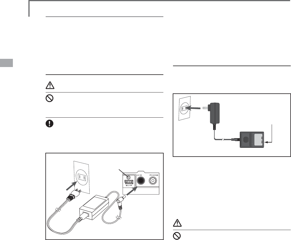
Always use the accessory AC adapter to charge
the battery.
The charging circuit is built into the T18MZ.
[Method of charging battery]
T18MZ
AC100V Charge lamp
1. Turn off the transmitter power.
2. Connect the power plug of the AC adapter
to an AC100V outlet.
*Don't connect AC plug to T18MZ without connecting with
AC100V.
3. Open the back lid of the transmitter and
insert the plug of the AC adapter into the
CHG port.
4. The charging monitor of the transmitter lights
red.
*The LCD screen will come on for several seconds and then
go off. It may take several tens of seconds for charging to
start after the AC adapter is connected.
5. When the battery is fully charged the
transmitter monitor will light green. A charge
plug is pulled out and an AC adaptor is
removed.
*After using the AC adapter always disconnect the power
cord from the AC outlet.
*The charging time when charging a completely discharged
battery pack is approximately 2 hours 30 seconds. However,
the actual charging time may be different from the above
depending on the ambient temperature and state of the
battery pack.
*If the battery is improperly installed or is faulty, the
transmitter monitor will not light and the battery will not be
charged.
How to charge the Li-Fe battery
FR2F1800(Option) for the receiver
Use the battery charger that is included in the set.
[Method of charging battery]
AC100V
3S2S
MODEL :
LBC-4E5
Intelligent LiFePO4 for 2S/3S Cells
Balance CHARGER
Red on, green off : Charging
Red flash : Output short-circuit or wrong polarity
Green on, red off : Charging Full
䃂The connector of the battery is
connected with "2S" side of
the charger.
䋨2S sids䋩
Charger LBC-4E5
1. Connect the power cable of the charger to
the wall socket (AC outlet).
2. Connect the connector to the Li-Fe battery.
&RQ¿UPWKDWWKHFKDUJLQJLQGLFDWRU/('ODPS5HGOLJKWV
3. Remove the battery after LED lamp Green
lighting .
*After completing the charge remove the battery from the
charger and remove the charger from the wall socket.
Warning
The transmitter battery cannot be charged with
the receiver charger. Conversely the receiver
battery cannot be charged with the transmitter
charger.
35
<Basic Operation>
How to turn ON/OFF the power of the
transmitter
Windows®&(LVLQVWDOOHGDVDEXLOWLQRSHUDWLQJ
system in the T18MZ transmitter. Compared to the
conventional system, the T18MZ takes extra time
for internal processing when it is turned on/off.
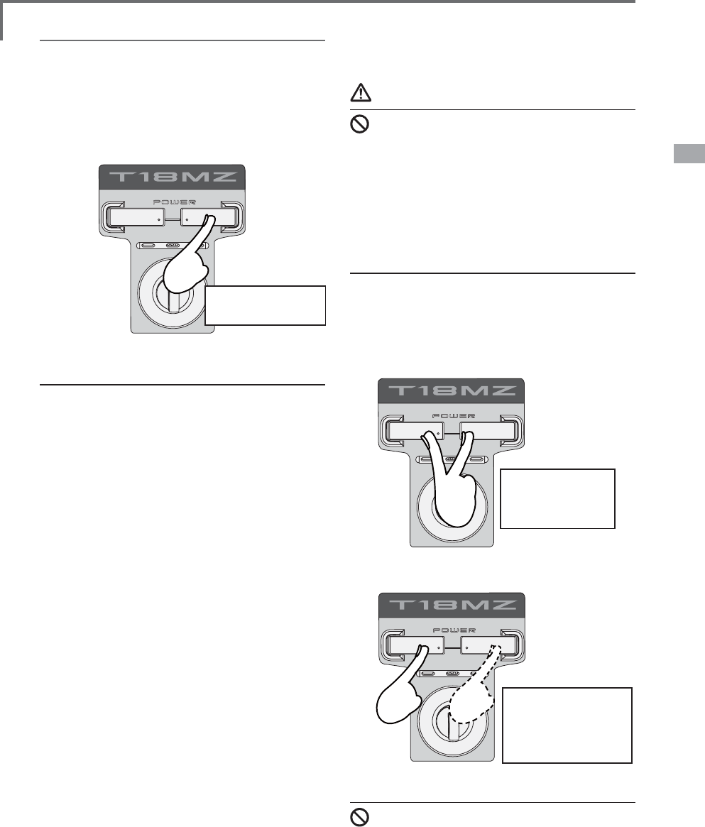
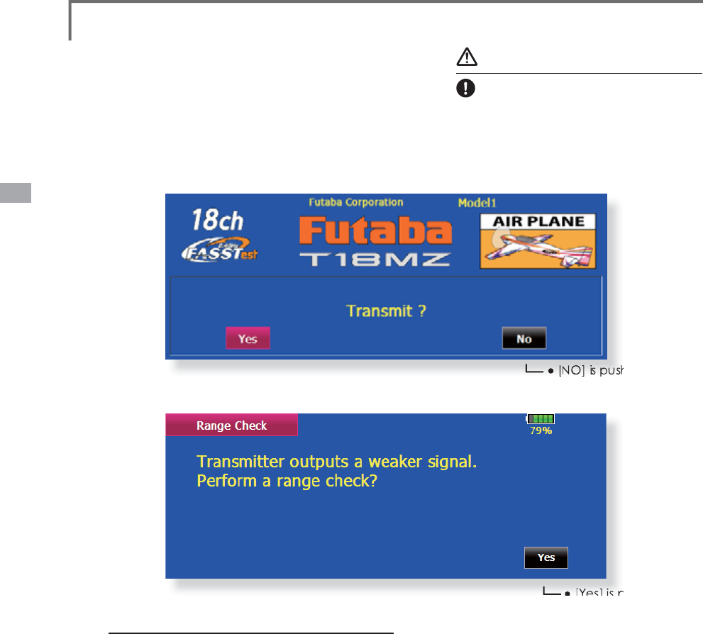
When turning on the power of the transmitter
1. Make a throttle stick slow.
2. Turn on the power switch of the transmitter.
$IWHULQLWLDOL]DWLRQRIWKHWUDQVPLWWHULVRYHU/('PRQLWRU
turns on Purple.
*If a throttle stick turns on by the high speed side (1/3 or
more), warning will become. If it returns slowly, warning
will stop and will become a "Transmit ?" screen.
*If you push the button "NO", then the transmitter will not
emit radio waves.
*If you push the button "Yes", then the transmitter will emit
radio waves.
Start-up time; The time required for initializing
the internal circuit of the transmitter varies between
the previous time you turned off the transmitter
and the time you will turned on the power. There
are two “start up” modes for your transmitter, see
below:
Cold start;
If you turn on the transmitter more than four
hours after you last turned it off, the mode is “Cold
start”. “Cold start” is normal for the first initial
power up of the day. It will take about 30 seconds
to be ready for use, as it takes time to initialize the
internal circuit of the transmitter.
Hot start;
If you turn on the transmitter less than four hours
after you last turned it off, the mode is “Hot start”.
Since initialization has been partly completed, the
transmitter will be ready to use in several seconds.
³+RWVWDUW´WDNHVSODFHXVXDOO\DWDVHFRQGÀLJKWRU
ODWHUÀLJKWLQWKHGD\
Warning
Once you turn on the power, never shut off the
power switch until the power becomes stable (or
XQWLOWKH¿UVWVFUHHQVKRZVXS,I\RXWXUQRII
the power switch while the transmitter is going
through the initialization process, the data could
be damaged. Note: The start-up time may be a
little bit slower when the SD card is installed
compared to when the card is not.
How to stop the transmitter
Turn off the power switch of the transmitter. The
internal circuit of the transmitter starts the shut
down process including saving the set-up data. The
/('ZLOOEOLQN\HOORZZKLOHWKHWUDQVPLWWHULVLQ
the shutdown process.
Once you turn off the power, never operate the
power switch until the power shutdown process
is fully completed. If you turn on the power
switch again while the transmitter is still in the
process of power shutdown, the data could be
damaged.
The right switch is
pushed.
It turns it off by
pushing 2 pieces
simultaneously.
It turns it off by
pushing 1 pieces
pushes for a long
time.
or
36 <Basic Operation>
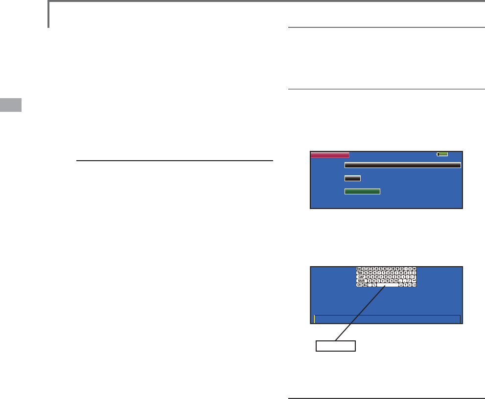
Registration of the user's name
T18MZ transmitter can register user's name.
How to register user's name
1. Turn on the power of the transmitter.
2. Push the area of the user's name shown on
the home screen or the "user's name" in the
linkage menu. Then the User's Name Set
screen will pop up.
85%
User Name Model1
User Name
User ID
Secure Mode
Futaba Corporation
0000
System
3. Push the user's name. Then the keyboard will
pop up. You can use up to 32 characters
as a user's name. Use the keyboard on the
screen to enter user's name.
space key
Enter and Exit : [Return] Key, Cancel and Exit : [ESC] Key
3LHDVHLQSXWXVHUQDPH۹&KDUDFWHUV
Futaba Corporation
4. Push "Return" key to return to the previous
screen after entering the user's name.
(If you want to protect the user's name)
If you don't want anybody else to change your
user's name, set your ID in the following way.
*Please be aware that you will not able to change user's name
if you forget your password.
1. Make sure that the security mode is "User's
name", and then push the User ID button.
2. Enter your password, using keyboard on the
screen.
You will need to enter your password for
changing the user's name from the next time
you turn on the power of the transmitter.
(YHQLI\RXHQWHUWKHVDPHFKDUDFWHU\RXUSDVVZRUGZLOOEH
identified differently depending on whether you are using
"Transform" mode or "Direct" mode for inputting.
As the internal circuit of the transmitter
stays on the standby mode for 4 hours after
turning off the power, some part of the circuit
is consuming current. When you turn on the
power during this period, the power starts
in “Hot mode”. But if more than four hours
pass after shutting down the power, the power
supply will completely shut down the internal
circuit. When you turn on the power after this
point, the power starts in “Cold start mode”.
How to reset software
If the screen freezes for some reason and you
cannot edit, the transmitter power supply is not shut
off even if you turn OFF the power switch. You
will need to use the remove the battery and reinsert
it again. In this case, the power restarts in “Cold
PRGH´(YHQWKRXJKWKHVFUHHQIUHH]HVDOOWKH
other functions for radio control operation remain
operative.
37
<Basic Operation>
T
imer
If one of two timer dis
p
la
y
s is
p
ushed, it can move to the
timer screen of a Linka
g
e
m
e
n
u.
W
arnin
g
Be sure to confirm the model name before fl
y
in
g
y
our aircraft.
Ch
ec
k
t
h
e rema
i
n
i
ng
b
attery as often as poss
ibl
e
and tr
y
to char
g
e the batter
y
earlier. If the batter
y
alarm makes a sound and its warning symbol is
di
sp
l
aye
d
,
l
an
d
your a
i
rcraft
i
mme
di
ate
l
y.
Ɣ$
O
W
K
RXJ
K
\RXPD\QRW
L
FHW
K
HI
OL
F
N
HU
L
QJRIW
K
HQXP
E
HUVRQW
K
H
L
CD screen
,
t
hi
s
i
s not an a
b
norma
l,
b
ecause t
h
e LCD screen
i
s
f
requent
l
y refres
hi
ng t
h
ose even
i
f t
h
ose num
b
ers are unc
h
ange
d
.
Ɣ<RXFDQD
GM
XVWW
K
H/&'FRQWUDVWDQ
G
W
K
H
E
DF
NOL
J
K
W
E
U
L
J
K
WQHVV
an
d
can c
h
ange t
h
e
d
urat
i
on t
i
me to turn off t
h
e
b
ac
kli
g
h
t an
d
co
l
or of t
h
e
b
ac
k
groun
d
b
y t
h
e screen sett
i
ng
i
n t
h
e system menu.
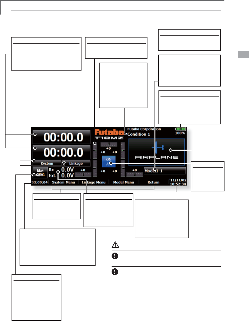
H
ome screen
C
ondition
T
he condition name
t
h
at
i
s current
l
y use
d
i
s
di
sp
l
a
y
e
d
h
ere.
3
XV
KWKL
V
D
U
HD
W
R
call the
C
ondition
S
elect screen.
C
lock
Thi
s s
h
ows t
h
e to
d
a
y
's
d
ate and the current time.
3XVKWK
L
VDUHD
I
RUWKH
Date & T
i
me Sett
i
ng
screen.
User
'
s name
P
ush
t
his
ar
e
a t
o
c
a
ll
t
he
U
ser's Name Settin
g
screen.
Sy
stem Selection
)$
66
7HVW
&
+
)$
66
7HVW
&
+
)$
66
70
8
/7
)$
66
7
&
+
6
)+
66
&
+
S
ystem t
i
mer
/
Reset
7K
L
VVKRZVWKHDFFXPXODWHG
ti
me up to now s
i
nce the latest
r
ese
t.
(
Hour
)
:
(
M
i
nute
)
:
(
Second
)
P
ush th
i
s area to reset the t
i
mer
.
D
irect buttons
S
elect and
p
ush one
o
f th
e
d
ir
ec
t
bu
tt
o
n
s
t
o
ca
ll
i
ts sett
i
n
g
screen.
+
HUHLVWKHKRPHVFUHHQDQGLWVGHVFULSWLRQV8VH
\
RXU¿Q
J
HURULQFOXGHGVW
\
OXVSHQWRRSHUDWHWKHWRXFK
sc
r
ee
n
.
(
Menu Button
)
ŏ0R
G
H
O
(
Menu Button
)
ŏ
6
\
VWHP
ŏ
/LQND
J
H
Batter
y
Indicator
:KHQWKHUHPDLQLQ
J
b
atter
y
reaches 30%,
t
he alarm will bee
p
.
L
and
y
our aircraft
i
mmediatel
y.
RF Indicator
2
1
$
,5
or
5)
2
))
Di
g
ital trim (T1 to T6, CD)
P
ush this area to call the
D
ial M
o
nit
o
r
sc
r
ee
n
.
M
o
d
e
l
N
ame
T
h
e
m
ode
l nam
e
that i
s
c
urrent
l
y use
d
i
s
di
sp
l
aye
d
h
ere.
3XVKWK
L
VDUHDWRFDOOWKH
Mo
d
e
l
S
e
l
ect screen
.
volta
g
e of Rx batter
y
Information from the
receiver is displaye
d
wi
t
h
an
bidi
r
ec
t
io
na
l
sy
stem.
38 <Basic Operation>
22:15:10
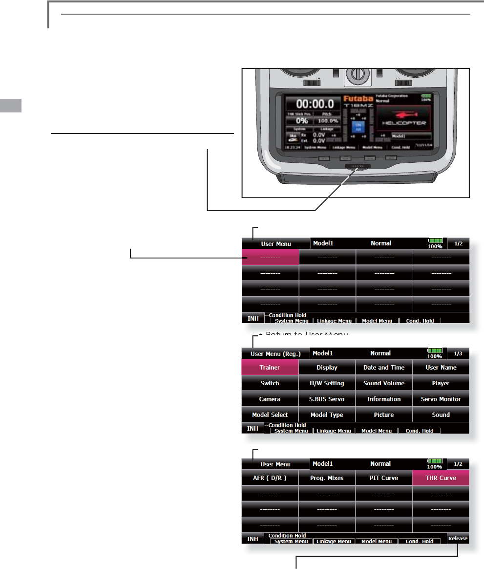
U
ser
M
enu
T
18MZ has each menu of a System
/
L
i
n
k
age
/
Mo
d
e
l
. User Menu can
b
e create
d
t
h
e
i
tem often use
d
by
i
tse
l
f for ot
h
ers can
b
e
chosen. Its own favorite original menu can be
GL
VS
O
D\H
G
L
I5RWDU\.H\
L
VSXV
K
H
G
H
ow to ma
k
e a
U
ser
M
enu
1. From a home screen, a Rotary key
i
s
pressed long t
i
me
.
2. The place to reg
i
ster
i
s pushed
.
3. S
i
nce all the
i
tems are d
i
splayed on all the
4 pages, an
i
tem to d
i
splay
i
s chosen
.
4. The User Menu o
f
all the 32
i
tems can be
created. From a home screen, a key
i
s
pressed
f
or a long t
i
me,
i
s called, and
i
s
use
d.
ŏ5
H
W
X
UQW
R
K
R
P
H
VF
U
HHQ
ŏ5HWXUQWR
K
RPHVFUHH
Q
ŏ
5HWXUQ
WR
8VHU
0HQX
ŏ,W
GH
O
H
W
HV
IU
R
P
D
XVH
UP
H
Q
X
It i
s
n
o
t
de
l
e
t
ed
fr
o
m th
e
m
e
n
u
o
f
a
bas
i
s.
*The item called from the user menu and the item called
I
URPWKHXVXDOPHQXDUHWKHVDPH&KDQ
J
HLVUHÀHFWHG
even
i
f ca
ll
e
d
from w
hi
c
h
.
39
<System Menu>
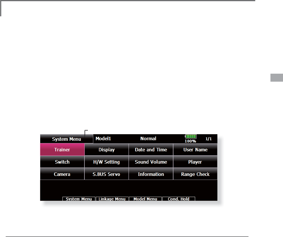
SYSTEM MENU
S
ystem Menu
f
unct
i
ons table
[
Trainer]: Starts and sets the trainer s
y
stem.
[
Displa
y
]: Displa
y
ad
j
ustment and auto power off settin
g
.
[
Date & T
i
me]: Sets t
h
e
d
ate an
d
t
i
me
(
s
y
stem c
l
oc
k
sett
i
n
g)
an
d
resets t
h
e t
i
mer.
[
User Name]: User name reg
i
strat
i
on an
d
ID P
i
n num
b
er.
[
Switch]: Toggle switch type setting (Set when the switch is replaced.)
[
H/W Settin
g
]: Hardware reverse / Stick settin
g
/ Calibration.
[
Sund Volume]: This volume is ad
j
usted. Ke
y
Operation/Error Warnin
g
/Trim&Center Click/Timer Event.
>
3
O
D\HU@5HSUR
G
XFW
L
RQRIPXV
L
F
¿O
H
[
Camera]: Funct
i
on t
h
at ta
k
es p
i
ctures w
i
t
h
a camera.
[
S.BUS Servo]: S.BUS servo setting.
[
Information]: Displa
y
s the pro
g
ram version, SD card information, and product ID.
[
Ran
g
e C
h
ec
k
]
:
T
h
e output of t
h
e transm
i
tter
i
s
l
owere
d
, an
d
t
h
e Ran
g
e c
h
ec
k
e
d
.
T
h
e S
y
stem Menu sets up funct
i
ons of t
h
e
t
ransmitter, this does not set up an
y
model data.
ŏ:KHQWKH6\VWHP0HQXEXWWRQ
L
VWRXFKHG
WKHPHQXVKRZQEHORZ
L
VFDOOHG&DOOWKH
VHWXSVFUHHQE\SUHVV
L
QJWKH
I
XQFW
L
RQ\RX
ZDQ
W
W
RVH
W
XS
ŏ5H
W
XUQ
W
R+RPHVFUHH
Q
40 <System Menu>
Trainer Trainer system startin
g
and settin
g
T18MZ trainer s
y
stem makes it possible for the
i
nstruct
i
on to c
h
ose w
hi
c
h
c
h
anne
l
s an
d
operat
i
on
m
o
d
es are to
b
e use
d
at t
h
e
i
nstructor's transm
i
tter.
B
ecause the switch and rate of each channel can
b
e set, t
h
e tra
i
n
i
ng met
h
o
d
can a
l
so
b
e matc
h
e
d
t
o t
h
e stu
d
ent's s
kill
l
eve
l
. Two transm
i
tters must
be connected b
y
an optional Trainer Cord, and the
Instructors’ transm
i
tter s
h
ou
ld
b
e programme
d
for
t
ra
i
ner operat
i
on, as
d
escr
ib
e
d
b
e
l
ow.
W
h
en t
h
e Instructor act
i
vates t
h
e tra
i
ner sw
i
tc
h,
t
he student has control of the aircraft (if MIX
/
FUNC/NORM mode is turned on, the Instructor
c
an ma
k
e correct
i
ons w
hil
e t
h
e stu
d
ent
h
as contro
l)
.
W
h
en t
h
e sw
i
tc
h
i
s re
l
ease
d
t
h
e Instructor re
g
a
i
ns
c
ontrol. This is very useful if the student gets the
ai
r
c
raft
i
nt
o
an
u
n
desi
ra
ble
si
t
u
at
io
n
.
ŏ6HWW
L
QJGDWDDUHVWRUHGWRPRGHOGDWD
ŏ6WXGHQWUDWHFDQEHDG
M
XVWHGDW0,;)81&
1
2
50PR
G
H
ŏ$FW
L
YDWHGVWXGHQWFKDQQHOVFDQEHVHOHFWHG
E\VZ
L
WFKHV
N
OTE: This trainer system can be used in the
f
ollowing manner
;
1
. In the T18MZ
(
including FX-40, T12Z and
T
12FG
)
transmitter and a conventional
t
ransmitter, if the channel order is different.
I
t is necessar
y
to match the channel order
i
n the Linka
g
e Menu when connectin
g
it
w
ith other than a T18MZ
.
2
. Be sure that all channels work correctl
y
in
E
RWKWUDQVPLWWHUVEHIRUHÁ\LQ
J
Corresponding types of transmitters and trainer mode settings:
7
\SHVRIWUDQVPLWWHU
V
,QVWUXFWRUVWUDQVPLWWHUVHWWLQ
JV
6WXGHQWVWUDQVPLWWHUVHWWLQ
JV
)
UHTVHWWLQ
J
7
UDLQHUVHWWLQ
J
)UHTVHWWLQ
J
7
UDLQHUVHWWLQ
J
7UDLQHU&RUGV
,
QVWUXFWR
U
6
WX
G
HQ
W
0
R
G
PR
G
H
&
+PR
GH
0R
G
PR
G
H
&
+PR
G
H
0
R
G
PR
GH
7
0= 7
0= $UELWUDU
\
&
+ $UELWUDU
\
&
+
-
)
*&
7U
DL
Q
H
U
&
RUGV
7
0=
70=
);
7=
7)*
);
$UE
L
WUDU
\
&
+3&0*
*
&+
330
7
0
=
7
)*
);
$
UE
L
WUDU
\
&
+
)
$
66
70/7
-
-
&+
)
$
66
708/7
7
0
=
7&7&
7
&7(;
7(;
$
UELWUDU
\
&
+
3
3
0
-
-
)*
7
UDLQHU
&
RUG
V
7
0=
7
&*
7
&*
$UE
L
WUDU
\
&
+ $UE
L
WUDU
\
-
-
)
*
7
UDLQHU&RUG
V
7
0= 7
-
7
-
$UE
L
WUDU
\
&
+ $UE
L
WUDU
\
-
-
)*
& 7UDLQHU
&
RU
G
V
70=
);
7
=
7)*
)
;
7
0
=
$
UE
L
WUDU
\
&+
$
UE
L
WUDU
\
&+
-
7
)
*
);
7
0
=
$UE
L
WUDU
\
&
+
$
UE
L
WUDU
\
&+
-
7
&
7
&*
7&
7
&
7
&*
7
-
7
0= $UE
L
WUDU
\
-
$UE
L
WUDU
\
&
+
-
*
It cannot
b
e use
d
by
t
h
e set of t
h
ose ot
h
er t
h
an a
di
a
g
ram.
(
As of Novem
b
er, 2011
)
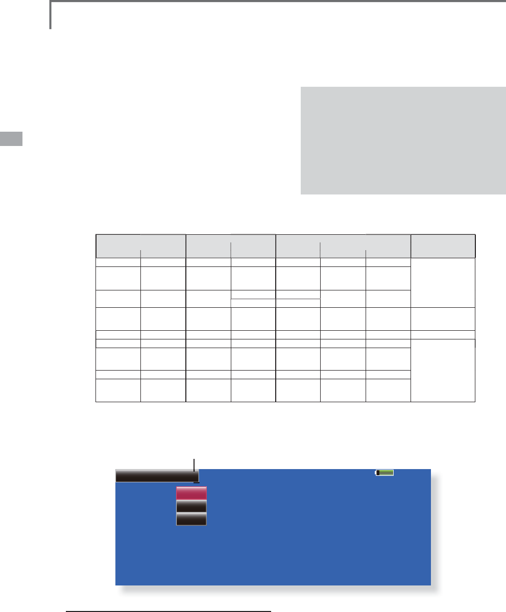
ŏ7RXFKWKH>7UD
L
QHU@EXWWRQDWWKH6\VWHP0HQXWR
FDOOWKHVHWXSVFUHHQ7KHVHWXSVFUHHQ
I
RUWKH
VWXGHQWPRGH
L
VVKRZQEHORZ
85%
Trainer
Student
INHACT/INH
8CHChannel
Teacher/Student
Model 1
S
tudent mode
6HW7HDFKHU
6WXGHQWEXWWRQWR6WXGHQW
&KDQJH$&7,1+EXWWRQ
I
URP,1+WR2))
RU
2
1
6
HWW
K
H
&
+PR
G
HWR
&
+
&
+
RU
&
+
VHHWKHDERYHFKDUW
I
RUWKHWUD
L
QHUPRGH
ŏ5HWXUQWR
6
\VWHP0HQ
X
VHWW
L
QJV
1RWH,Q
VWX
G
HQWPR
G
H
RQ
O
\W
K
HWHDF
K
H
U
V
L
GHFDQWXUQRQDQGR
II
WKHSRZHUR
I
WKH
VWXGHQWVWUDQVP
L
WWHU.HHSWKHSRZHUVZ
L
WFK
DOZD\VDWR
II
SRV
L
W
L
RQ
41
<System Menu>
T
e
a
c
h
e
r m
ode
6
HW
7HDF
K
HU
6
WX
G
HQW
E
XWWRQWR
7HDF
K
HU
&KDQJH$&7,1+EXWWRQ
I
URP,1+WR2))
RU
2
1
6
HWW
K
H
&
+PR
G
HWR
&
+
&
+
RU
&
+
VHHWKHDERYHPHQW
L
RQHGFKDUW
I
RUWKH
WUD
L
QHUPRGHVHWW
L
QJV
&DOOXSWKH6Z
L
WFK6HWW
L
QJVFUHHQE\WRXFK
L
QJ
6Z
L
WFK7KHQVHWWKHGHV
L
UHGVZ
L
WFKDQGRQ
R
II
G
L
UHFW
L
RQ
6HOHFWWKHVZ
L
WFKPRGH,
I
\RXVHOHFW1250
WKHWUD
L
QHU
I
XQFW
L
RQZ
L
OOEHWXUQHGRQRUR
II
E\DVZ
L
WFKSRV
L
W
L
RQ,
I
\RXVHOHFW$/721
DQG2))R
I
WKHWUD
L
QHU
I
XQFW
L
RQVZ
L
WFKHV
DOWHUQDW
L
YHO\HYHU\W
L
PHWKHVZ
L
WFK
L
VWXUQHG
RQ7K
L
VPHDQVWKHVWXGHQWV
L
GHFDQEH
RSHUDWHGZ
L
WKRXWKROG
L
QJWKHVZ
L
WFKOHYHU
7KH,QVWUXFWRUV
L
GHVHOHFWVWKHFKDQQHO
I
RUFRQWURO7KUHHRSHUDW
L
QJPRGHVDUH
DYD
L
ODEOH
"NORM" mode
(
Normal mode
);
6WXGHQWV
L
GHKDVQRFRQWUROR
I
P
L
[HVDQG
VHWW
L
QJV
L
Q7HDFKHUVUDG
L
R
"
MIX
"
mo
d
e
;
6WXGHQWKDV
I
XOODGYDQWDJHR
I
DOOVHWW
L
QJ
L
Q
7
HDFKHUVUDG
L
RSOXV7HDFKHUKDVWKHRSW
L
RQWR
FKDQJHDQ\VHWW
L
QJZK
L
OH6WXGHQWKDVFRQWURO
"
FUNC" mode
(
Function mode
);
6
WXGHQWKDVFRQWURORIPL[HVDQGUDWHVHWWLQ
J
V
R
I7
HDF
K
H
U
V
U
DG
L
R
6
HWWKHVZLWFKHVDQGUDWHVRIHDFKFKDQQHO
6
ZLWFKWRWKHGHWDLOVVHWX
S
VFUHHQE
\
WRXFKLQ
J
WKHSD
J
HVZLWFKLQ
J
EXWWRQ>@
DWWKHWRSUL
J
KWKDQGFRUQHURIWKHVFUHHQ
6
WXGHQWR
S
HUDWLRQIRUHDFKFKDQQHOFDQEH
VH
WK
H
U
H
>
6ZLWFK
@
7KHVZLWFKHVWKDWFDQEHR
S
HUDWHG
E\
WKHVWXGHQWFDQEHVHW6:$a6:+66
DQG
66
FDQEHVHOHFWHG
>
5DWH
@
6HUYRWUDYHOYHUVXVVWXGHQWR
S
HUDWLRQ
FDQEHVHW
7KLVFDQRQO\EHXVHGLQWKH
)
8
1
&
/
0,;1250PRGHV
1RWH,QWHDFKHUPRGH
WKHWUDLQHUIXQFWLRQ
ZR
Q·W
EH
W
X
UQ
HG
R
Q
X
QO
HVV
WK
H
,Q
V
WU
XF
W
R
U
V
WUDQVPLWWHUUHFHLYHVVL
J
QDOVIURPWKHVWXGHQWV
WU
D
Q
V
PLWW
H
U
%
H
VX
U
H
W
R
FR
QILUPWKL
V
D
IW
H
U
F
RQQHFWLQ
J
\RXUWUDLQHUFDEOH
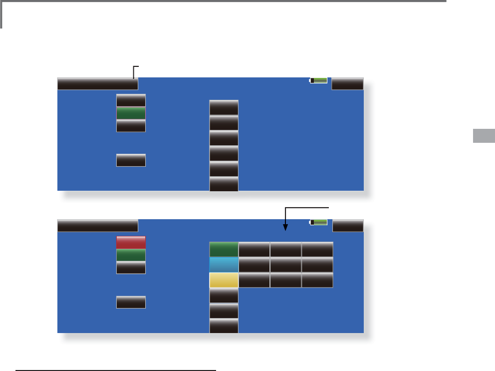
85%
Trainer 1/3
Teacher
INHACT/INH CH Function Mode Switch Rate Stu.CH
1 ELE
2 ELE2
3 RUD
4 AIL
5 AIL2
6 THR
8CHChannel
OFF
OFF
OFF
OFF
OFF
OFF
OFF
OFF
OFF
Master SW
Teacher/Student
Model 1
ŏ
5HWXUQWR6
\
VWHP0HQX
85%
Trainer 1/3
Teacher
INHACT/INH CH Function Mode Switch Rate Stu.CH
1 ELE
2 ELE2
3 RUD
4 AIL
5 AIL2
6 THR
8CHChannel
OFF
FUNC
MIX
OFF
OFF
NORM
OFF
OFF
OFF
Master SW
Teacher/Student
Model 1
NULL
NULL
NULL
+100
+100
+100
CH 2
NULL
CH 4
ŏ
6
WXGHQWUDWH
ŏ7KHVHWX
S
VFUHHQIRUWKHLQVWUXFWRUPRGHLV
V
K
R
ZQ
EH
O
R
Z
42 <System Menu>
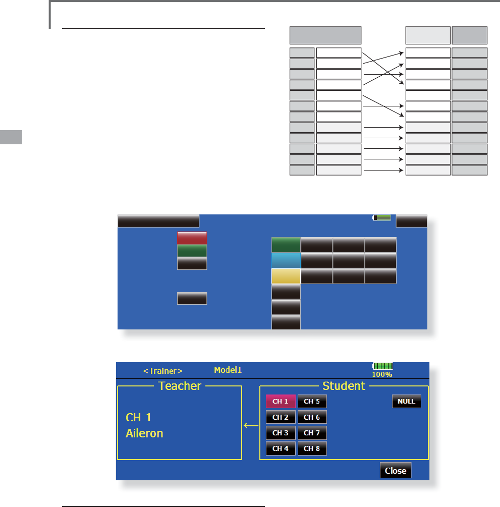
Student channel settin
g
2
S
HQWKH6
\
VWHP0HQXWUDLQHUVFUHHQ
6HOHFW
>
7HDFKHU
@
:KHQ
>
)81&
@>
0,;
@>
1250
@
LVVHOHFWHGDVWKH
PRGHRIWKHFKDQQHOWREHVHWWKH
>
6WXGHQW
&+@VHWWLQ
J
EXWWRQLVGLVSOD\HG
:KHQ
>2))@>6WXGHQW&+@VHWWLQ
J
LVQRWSHUIRUPHG
:KHQWKH
>
6WXGHQW&+
@
EXWWRQLV
S
UHVVHGWKH
&KDQQHO6HOHFWVFUHHQLVGLV
S
OD
\
HG6HOHFW
WK
H
F
K
D
QQ
H
O
Tra
i
ner student channel sett
i
ng
f
unct
i
on
W
hi
c
h
c
h
anne
l
of t
h
e s
i
gna
l
from t
h
e stu
d
ent
t
ransm
i
tter
i
s fetc
h
e
d
as t
h
e stu
d
ent funct
i
on
i
nput
s
i
g
nal when "FUNC""MIX""NORM" is set as the
t
ra
i
n
e
r f
u
n
c
t
io
n
s
t
ude
nt'
s
tran
s
m
i
tt
e
r m
ode
c
an
b
e set. T
hi
s ma
k
es tra
i
ner connect
i
on eas
y
even
when the instruction side and student side channel
ass
i
gnment
i
s
di
fferent.
85%
Trainer 1/3
Teacher
INHACT/INH CH Function Mode Switch Rate Stu.CH
1 ELE
2 ELE2
3 RUD
4 AIL
5 AIL2
6 THR
8CHChannel
OFF
FUNC
MIX
OFF
OFF
NORM
OFF
OFF
OFF
Master SW
Teacher/Student
Model 1
NULL
NULL
NULL
+100
+100
+100
CH 2
NULL
CH 4
Student side Student CH
CH1 Aileron
CH2 Elevator
CH3 Throttle
CH4 Rudder
CH5 Gear
CH6 Flap
CH7 Aileron2
CH8 Aux5
CH9 Aux4
CH10 Aux3
CH11 Aux2
CH12 Aux1
Instructor side
CH2Elevator CH4Rudder CH3Throttle CH1Aileron --Aileron2 CH6Flap CH5Gear CH8Aux5 CH9Aux4 CH10Aux3 CH11Aux2 CH12Aux1
([DPSOHRIVWXGHQW&+VHWWLQ
J
!

43
<System Menu>
Model 1
85%
Display
-+
-+
30Min.
1Min.
$XWR3RZHURíWLPH
Backlight decrease
Back color Touch screen
%DFNOLJKWGHFUHDVHWLPH
Backlight
TEXT TEXT TEXT TEXT TEXT Cal.
Auto power o
ff
t
i
me sett
i
n
g
$G
M
XVWWKHDXWRSRZHURIIWLPHZLWKWKHOHIW
D
QGUL
J
KWVLGHEXWWRQV
*W
hen the time the transmitter is inactive exceeds the se
t
time, the power is turned off automaticall
y
. This time can be
set u
p
to 1 hour in 10 minutes increments. The auto
p
ower
o
ff funct
i
on can a
l
so
b
e
d
eact
i
vate
d
.
*
An audible alarm is sounded and an alarm screen is
displayed from 3 minutes before auto power off and
t
h
e t
i
me rema
i
n
i
ng unt
il
auto power off
i
s
di
sp
l
aye
d
.
W
h
en a st
i
c
k
or sw
i
tc
h
i
s operate
d
w
hil
e t
h
e a
l
arm
screen is bein
g
displa
y
ed, the alarm is cleared and
the display is returned to the home screen.
Backli
g
htin
g
bri
g
htness ad
j
ustment
$G
M
XVWWKHEDFNOL
J
KWLQ
J
EUL
J
KWQHVVZLWKWKH
O
HIWDQGUL
J
KWVLGHEXWWRQV
*
W
h
en t
h
e r
igh
t s
id
e
b
utton
i
s touc
h
e
d
, t
h
e
b
ac
kligh
t
i
n
g
b
ecomes
b
r
igh
ter. W
h
en t
h
e
l
eft s
id
e
b
utton
i
s touc
h
e
d
, t
h
e
b
ac
kli
g
h
t
i
ng
b
ecomes
d
ar
k
er.
Backli
g
ht decrease bri
g
htness ad
j
ustment
$G
M
XVWWKHEDFNOL
J
KWGHFUHDVHEUL
J
KWQHVVZLWK
W
KHOHIWDQGUL
J
KWVLGHEXWWRQV
*
When the ri
g
ht side button is touched, the backli
g
htin
g
b
ecomes
b
r
igh
ter. W
h
en t
h
e
l
eft s
id
e
b
utton
i
s touc
h
e
d
, t
h
e
b
ac
kligh
t
i
n
g
b
ecomes
d
ar
k
er.
*
It cannot be made bri
g
hter than Backli
g
htin
g
bri
g
htness
adj
ustment.
Backli
g
ht decrease time
<
RXFDQVHWDWLPH
S
HULRGWRGHFUHDVHWKH/&'
E
DFNOL
J
KW7KLVIXQFWLRQFRXQWVWKHSHULRG
Display
/
&'VFUHHQDG
M
XVWPHQWDQGDXWRSRZHURIIVHWWLQ
J
T
h
e fo
ll
ow
i
n
g
LCD screen a
dj
ustments an
d
auto
power off settin
g
are possible:
ŏ
$XWRSRZHURIIWLPHVHWWLQ
J
ŏ
%DFNOL
J
KWLQ
J
EUL
J
KWQHVVDG
M
XVWPHQW
ŏ
%DFN
J
URXQGFRORUFKDQ
J
H
ŏ
7RXFK
S
DQHOVFUHHQ
S
RVLWLRQFRUUHFWLRQ
ŏ
7RXFKWKH
>
'LV
S
OD
\@
EXWWRQLQWKH6
\
VWHP0HQXWR
F
DOOWKHVHWX
S
VFUHHQVKRZQEHORZ
ŏ
5HWXUQWR6
\
VWHP0HQX
WK
DWW
K
HWRXF
K
SDQH
O
K
DV
E
HHQQRWRSHUDWH
G
7
K
L
VW
L
PHFDQEHVHWE\WHQVHFRQGVWHSV<RX
F
DQDOVRWXUQR
II
WKHEDFNO
L
JKWGHFUHDVHµ
LI
\
RXO
L
NH
*The backlight consumes a large amount of power. We
r
ecommend you to turn off the backlight by setting the
b
acklight power-off time to about one minute.
*Since the backlighting power consumption is extremely
h
igh, we recommend that the backlighting off time be made
short.
B
ackground color
7RXFKWKHEXWWRQRIWKHFRORU
\
RXZDQWWR
FKDQJH
7KHUHDUH¿YHEDFNJURXQGFRORUV
T
ouc
h
sc
r
ee
n
c
ali
b
rati
o
n
7K
L
V
I
XQFW
L
RQDG
M
XVWVWKHORFDW
L
RQR
I
WRXFK
SDQHO7RXFK&DO
L
EUDW
L
RQEXWWRQDQGWKHQ
SUHVV<HVWKHFDO
L
EUDW
L
RQVFUHHQZ
L
OOSRS
XS7RXFKWKHFHQWHUR
I
WKHFURVVKD
L
UFXUVR
U
RQWKHVFUHHQZ
L
WKWKHVW\OXVSHQ$VVRRQDV
WKHV\VWHPUHFRJQ
L
]HVWKHSRV
L
W
L
RQWKHFXUVR
U
Z
L
OOPRYHRQWRWKHQH[WSRV
L
W
L
RQ5HSHDW
WK
L
VSURFHGXUHDVORQJDVWKHFXUVRUPRYHV
WRQH[WSRV
L
W
L
RQ<RXZ
L
OOGRWK
L
V
IL
YHW
L
PHV
&DO
L
EUDW
L
RQZ
L
OOEHFDUU
L
HGRXWEDVHGRQWKH
IL
YHSRV
L
W
L
RQV'
L
VDSSHDUDQFHR
I
WKHFURVV
KD
L
UFXUVRUPHDQVWKHFDO
L
EUDW
L
RQKDVEHHQ
FRPSOHWHG7RXFKDQ\SR
L
QWRQWKHVFUHHQ
WRUHWXUQWRWKHSUHY
L
RXVVFUHHQ
*In ordinary operation, this calibration is not necessary. I
f
y
ou notice the touch panel is not functionin
g
correctl
y
after
lon
g
use, we recommend
y
ou to carr
y
out this calibration.
44 <System Menu>
Model 1 85%
Date and Time
System Timer
Date
2011 8 17
August 2011
SMTWTFS
31 123456
456
78910
78910
11 12 13
18 19 2014 15 16
24 25 26 2721 22 23
31 12 328 29 30
17
Time
16
Total 00:17:48
35 52
Date settin
g
7RXFKWKH<HDU0RQWKRU'D
\
EXWWRQ
DQGVHWWKHGDWHE\WRXFKLQ
J
WKH>@RU>@
EX
WW
R
Q
*
T
h
e
d
ate can a
l
so
b
e set
by
press
i
n
g
t
h
e
d
ate on t
h
e ca
l
en
d
ar
show
n at t
he
le
ft
.
T
i
me sett
i
n
g
7RXFKWKH+RXURU0LQXWHEXWWRQ
DQGVHW
WKHWLPHE\WRXFKLQ
J
WKH>@RU>@EXWWRQ
:KHQWKH6HFRQGEXWWRQLVWRXFKHG
WKH
WLPHULVVHWWR
VHFRQGV
Integrat
i
ng t
i
mer reset
7KHLQWHJUDWLQJWLPHUVKRZVWKHWRWDOWLPH
WKDWKDVHODSVHGVLQFHWKHODVWUHVHWWLQJ
:KHQWKH>6\VWHP7LPHU@EXWWRQLVWRXFKHG
WKHWLPHULVUHVHW
Date and Time
'
DWHDQGWLPHVHWWLQ
J
V\VWHPFORFNVHWWLQ
J
DQGLQWH
J
UDWLQ
J
WLPHUUHVHWWLQ
J
This function ad
j
usts the s
y
stem clock of the
T18MZ transm
i
tter. Perform t
hi
s sett
i
ng w
h
en you
purc
h
ase t
h
e set an
d
w
h
en a
dj
ustment
i
s necessar
y
.
ŏ
7RXFKWKH>'DWHDQG7
L
PH@EXWWRQ
L
QWKH6\VWHP
0
HQXWRFD
OO
W
K
HVHWXSVFUHHQV
K
RZQ
E
H
O
RZ
T
he inte
g
ratin
g
timer can also be reset.
*The inte
g
ratin
g
timer is displa
y
ed on the Home screen.
ŏ5HWXUQWR6\VWHP0HQ
X

45
<System Menu>
85%
User Name Model1
User Name
User ID
Secure Mode
Futaba Corporation
0000
System
User Name
8
VHUQDPHUH
J
LVWUDWLRQDQG3,1VHWWLQ
J
T
his function re
g
isters the T18MZ user name.
A PIN can a
l
so
b
e set to protect t
h
e set
d
ata o
r
user name.
ŏ7RXFKWKH
>
8VHU1DPH
@
EXWWRQDWWKH6\VWHP0HQX
WRFD
OO
W
K
HVHWXSVFUHHQV
K
RZQ
E
H
O
RZ
*
Set t
h
e PIN carefu
ll
y. W
h
en a system PIN
i
s set,
i
f you
forget the PIN, none of the settings can be changed. In this
case, the system must be reset by the Futaba Service Center.
ŏ5HWXUQWR
6
\VWHP0HQ
X
User name registration
:KHQWKH8VHU1DPHER[
L
VWRXFKHGD
N
H\
E
RDU
G
DSSHDUVRQW
K
HVFUHHQ
(QWHUWKHXVHUQDPH
I
URPWK
L
VNH\ERDUG
*
A user name of up to 32 c
h
aracters can
b
e entere
d
.
*
T
h
e set user name
i
s
di
sp
l
a
y
e
d
on t
h
e Home screen.
(For a detailed descri
p
tion of the in
p
ut method, see [Use
r
Name Re
g
istration/Character Input Method] in the Basic
O
perat
i
on sect
i
on.
)
User name or set data
p
rotection
7RXFKWKH6HFXU
L
W\0RGHEXWWRQDQGVHOHFW
W
KHPRGH7KHPRGH
L
VVZ
L
WFKHGHDFKW
L
PH
W
KHEXWWRQ
L
VWRXFKHG
*
User Name: Se
l
ect w
h
en you want to protect t
h
e user name
o
nly.
*
System: Se
l
ect w
h
en you want to protect a
ll
t
h
e set
d
ata.
:KHQWKHXVHU,'EXWWRQLVWRXFKHG
D3,1
L
Q
S
XWVFUHHQD
SS
HDUV,Q
S
XWD3,1RIX
S
WR
G
L
J
LWV
:KHQWKH5HWXUQNH
\
LVWRXFKHGWKH
G
LVSOD\UHWXUQVWRWKHSUHFHGLQ
J
VFUHHQ
:KHQWKHWUDQVPLWWHU
S
RZHULVWXUQHGRIIWKH
V
HWVHFXULW
\
PRGHEHFRPHVDFWLYH
*
W
h
en a PIN
i
s set at t
h
e user name
,
i
t must
b
e entere
d
t
h
e
n
ext t
i
me t
h
e User Name screen
i
s opene
d
.
Wh
en a S
y
stem PIN
i
s set, a
b
utton
di
sp
l
a
yi
n
g
a
k
e
y
i
con
appears on t
h
e Home screen.
Wh
en
y
ou want to c
h
an
g
e t
h
e sett
i
n
g
, touc
h
t
hi
s
b
utton an
d
enter t
h
e PIN.
,I
\
RXZDQWWRQXOOLI
\
\
RXUFXUUHQW
S
DVVZRUG
VHWWKHSDVVZRUGWR
GHIDXOWYDOXH
46 <System Menu>
85%
Switch Lock
Lever
SW Type Posi. Ait/Mom 3P Mom
3Posi. Alt.
Lever
SB 2Posi. Alt.
Lever
SC 3Posi. Alt.
Lever
SD 3Posi. Alt.
Lever
SE
SW Type Posi. Ait/Mom 3P Mom
3Posi. Alt.
Lever
SF 2Posi.
2Posi.
2Posi.
Alt.
Lever
SG Alt.
Lever
SH Mom.
SA
S
w
i
tch select
i
on
6HOHFWWKHVZ
L
WFKW\SHE\WRXFK
L
QJWKH>W\SH@
E
XWWRQFRUUHVSRQG
L
QJWRWKHVZ
L
WFKWREH
U
HS
O
DFH
G
>
/HYHU@7RJJOHVZ
L
WFK
>
%XWWRQ
@
3XV
KE
XWWRQ
>
'
L
DO@.QRE
ŏ
6HWW
L
QJ
I
RUWRJJOHVZ
L
WFK
L
VVKRZQDERYH
2/
3 pos
i
t
i
on select
i
on
7RXFKWKH3RV
L
EXWWRQFRUUHVSRQG
L
QJWRWKH
V
Z
L
WFKDQGVHOHFWWKHSRV
L
W
L
RQW\SH
>
3RV
L
@SRV
L
W
L
RQ
>
3RV
L
@SRV
L
W
L
RQ
Switch 7R
JJ
OHVZLWFKW\SHVHWWLQ
J
6HWWLQ
J
ZKHQWKHVZLWFKZDVUHSODFHG
I
f
y
ou modif
y
the location of the switches on the
r
i
g
h
t an
d
l
eft
(
top
)
of t
h
e transm
i
tter, you s
h
ou
ld
b
e sure to re-ass
ig
n funct
i
ons to t
h
e sw
i
tc
h
es fo
r
p
ro
p
er o
p
eration.
A
“Loc
k
”
i
s
i
nc
l
u
d
e
d
to prevent sett
i
n
g
s from
bein
g
modified b
y
mistake. When
y
ou need to
ch
ange sett
i
ngs, un
l
oc
k
t
hi
s
b
y press
i
ng “Loc
k
”
it
w
ill
t
h
en rea
d
”Un
l
oc
k
” an
d
y
ou can ma
k
e c
h
an
g
es
a
s re
q
uired.
ŏ7RXFKWKH
>
6ZLWFK
@
EXWWRQDWWKH6
\
VWHP
0HQXWRFDOOWKHVHWX
S
VFUHHQVKRZQEHORZ
ŏ5HWXUQWR6
\
VWHP0HQ
X
[
Alt
/
Mom
]
mode select
i
on
6HOHFWWKHRSHUDW
L
RQPRGHE\WRXFK
L
QJ
WKH>$OW0RP@EXWWRQFRUUHVSRQG
L
QJWRWKH
VZ
L
WFK
>
$
O
W
@
$
O
WHUQDWHW\S
H
>0RP@6HO
I
UHWXUQW\S
H
ŏ6HOHFW
L
RQR
I
WKH>0RP@PRGHZ
L
WKD
SRV
L
W
L
RQW\SHVZ
L
WFK
L
VVKRZQDERYH
"3
P Mom
"
mode select
i
on
6HOHFWWKHRSHUDW
L
RQPRGHE\WRXFK
L
QJ
WKH30RPEXWWRQFRUUHVSRQG
L
QJWRWKH
VZ
L
WFK
>6
L
QJOH@2QHV
L
GHVHO
I
UHWXUQW\S
H
>'XDO@%RWKG
L
UHFW
L
RQVVHO
I
UHWXUQW\S
H
47
<System Menu>
Op
eration direction reversal method
7RXFKWKHVHWW
L
QJEXWWRQFRUUHVSRQG
L
QJWR
WKH+:
+DUGZDUH
\RXZDQWWRUHYHUVH
5HYHUVHWKH+:E\WRXFK
L
QJ><HV@
:KHQ
\RXZDQWWRVWRSRSHUDW
L
RQWRXFK>1R@
>1RUPDO@1RUPDORSHUDW
L
RQG
L
UHFW
L
R
Q
>5HYHUVH@5HYHUVHVWKHRSHUDW
L
RQG
L
UHFW
L
RQ
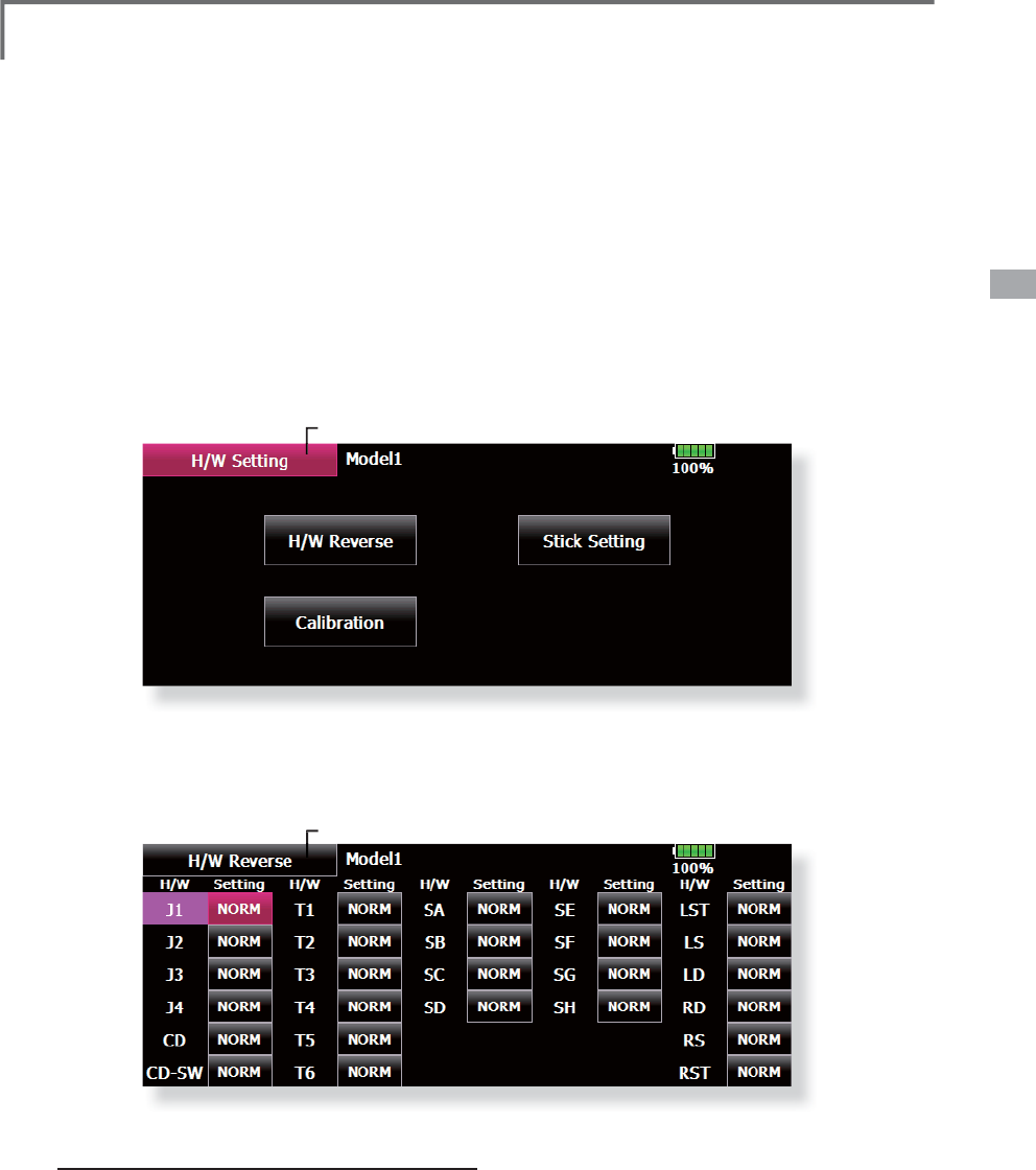
H/W Setting 6WLFNVZLWFKWULPOHYHUDQGNQRERSHUDWLRQGLUHFWLRQUHYHUVDO
+DUGZDUH
UHYHUVH
6WLFNUHVSRQVHDQGKLVWHULVLVDG
M
XVWPHQW
6WLFN6HWWLQ
J
&DOLEUDWLR
Q
T
his function is for ad
j
ustin
g
the sticks, switches,
an
d
tr
i
mm
e
r
s
ch
ara
c
t
e
r
is
t
ics.
It
is
n
o
t
used
wi
t
hou
t
n
ecess
i
t
y
.
H/W
Reverse
T
his function reverses the operation si
g
nal of the
s
ticks
,
switches
,
trimmer levers
,
and knobs.
Note: Th
i
s sett
i
ng reverses the actual operat
i
on
signal, but does not change the display of
the
i
nd
i
cators on the d
i
splay. Use the Normal
mode as long as there
i
s no spec
i
al reason to
use the Reverse mo
d
e
.
ŏ7RXFKWKH>+:6HWWLQJ@EXWWRQDWWKH6\VWHP
0HQXWRFD
OO
W
K
HVHWXSVFUHHQV
K
RZQ
E
H
O
RZ
ŏ5HWXUQWR6\VWHP0HQ
X
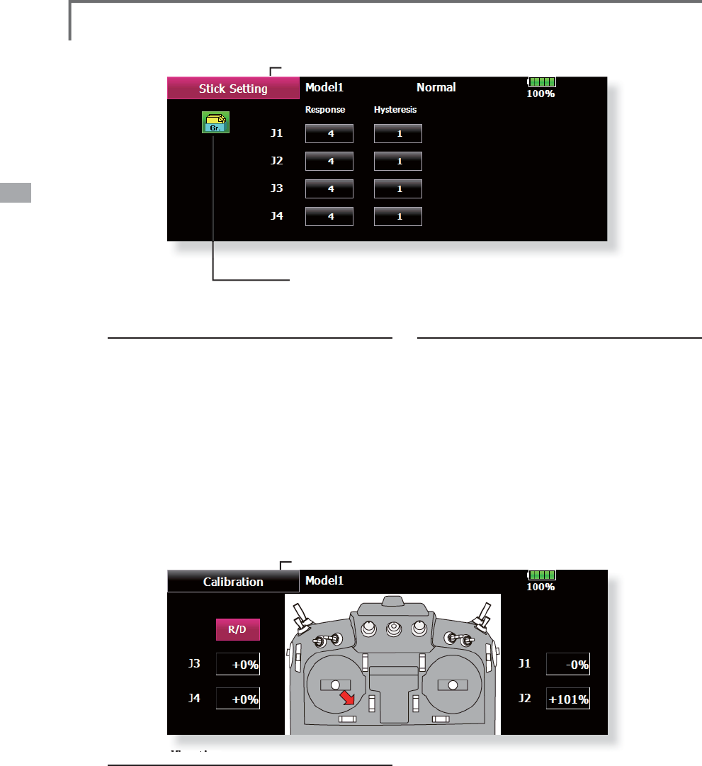
Stick Settin
g
This function sets the servo res
p
onse and
hysteresis for stick operation for each condition.
Th
e contro
l
fee
li
ng of t
h
e st
i
c
k
can
b
e a
dj
uste
d
to
match the aerobatics.
C
alibration
Usually, this calibration is unnecessary.
Please perform this calibration, if a
g
ap of a stick
should arise in prolonged use.
ŏ7RXF
K
W
K
H
>
+
:5HYHUVH
@
E
XWWRQDWW
K
H+
:
6HWW
L
QJ0HQXWRFDOOWKHVHWXSVFUHHQVKRZQ
E
H
O
RZ
ŏ5HWXUQWR+:6HWW
L
QJ0HQ
X
48 <System Menu>
Response ad
j
ustment
7RXFKWKHVHWWLQ
J
EXWWRQFRUUHVSRQGLQ
J
WR
W
KHVWLFNZKRVHUHVSRQVH\RXZDQWWRDGMXVW
$
G
M
XVWPHQWEXWWRQVDSSHDURQWKHULJKW
K
DQGVLGHRIWKHVWLFNVHWX
S
VFUHHQ
8VHWKHDG
M
XVWPHQWEXWWRQVWRDG
M
XVWWKH
U
HV
S
RQVH
,
QLWL
D
OY
D
O
XH
$
G
M
XVWPHQWUDQJHa
:KHQWKHDG
M
XVWPHQW
Y
DOXHLVODU
J
HWKHUHVSRQVHEHFRPHVVORZ
How to Calibration
$VW
L
FNWRFDUU\RXWDFDO
L
EUDW
L
RQE\U
L
JKWDQG
O
H
I
W
L
VFKRVHQ
7KHVW
L
FN
L
VPDGHQHXWUDODQGD>QHXWUDO@
E
XWWRQ
L
VSXVKHG
7KHVW
L
FN
L
VPDGH
I
XOOU
L
JKWDQG
I
XOOERWWRP
W
KH>5
L
JKW%RWWRP@EXWWRQ
L
VSXVKHG
(
7K
H
GL
UHFW
L
RQR
I
DQDUURZ
7KHVW
L
FN
L
VPDGH
I
XOOOH
I
WDQG
I
XOOWRSWKH>/H
I
W
7
RS@EXWWRQ
L
VSXVKHG
(
7
KHG
L
UHFW
L
RQR
I
DQ
D
UURZ
ŏ
7RXFKWKH>6W
L
FN6HWW
L
QJ@EXWWRQDWWKH+:6HWW
L
QJ
0
HQXWRFD
OO
W
K
HVHWXSVFUHHQV
K
RZQ
E
H
O
RZ
ŏ
7RXFKWKH>&DO
L
EUDW
L
RQ@EXWWRQDWWKH+:6HWW
L
QJ
0
HQXWRFD
OO
W
K
HVHWXSVFUHHQV
K
RZQ
E
H
O
RZ
ŏ
5HWXUQWR+:6HWW
L
QJ0HQX
ŏ
*URXSV
L
QJOHPRGHVZ
L
WFK
L
QJ
*U6QJO
(
For more information, see the descri
p
tion at the back of this manual.)
Hysteres
i
s ad
j
ustment
7RXFKWKHVHWWLQ
J
EXWWRQFRUUHVSRQGLQ
J
WR
W
KHVWLFNZKRVHK\VWHUHVLV\RXZDQWWRDGMXVW
$
G
M
XVWPHQWEXWWRQVDSSHDURQWKHULJKW
K
DQGVLGHRIWKHVWLFNVHWX
S
VFUHHQ
8VHWKHDG
M
XVWPHQWEXWWRQVWRDG
M
XVWWKH
K\
VWHUHVLV
,
QLWL
D
OY
D
O
XH
$
G
M
XVWPHQWUDQJHa
:KHQWKH
D
G
M
XVWPHQWYDOXHLVODU
J
HWKHK\VWHUHVLVYDOXH
E
HFRPHVODU
J
H
ŏ5HWXUQWR+:6HWW
L
QJ0HQ
X
*
P
l
ease
d
o not pus
h
a st
i
c
k
too muc
h
strong
l
y.
*
An after-en
d
s
h
ou
ld
c
h
ec
k
t
h
at t
h
e neutra
l
0
%
an
d
b
ottom
r
igh
t s
id
e w
ill
b
e +100%, an
d
t
h
e top
l
eft s
id
e
h
as
b
ecome
-100
%
.
49
<System Menu>
Model 1 85%
Sound Volume
-+
-+
-+
-+
Key Operation
Trim & Center Click
Error/Warning
Timer Event
Sound Volume 6RXQG9ROXPHVHWWLQ
J
T
his function can set the volume of "Ke
y
Operat
i
on" "Error
/
Warn
i
ng" "Tr
i
m&Center C
li
c
k
"
"T
i
mer Event" respect
i
ve
ly
.
*
Set t
h
e PIN carefu
ll
y. W
h
en a system PIN
i
s set,
i
f you
f
orget the PIN, none of the settings can be changed. In this
case, the system must be reset by the Futaba Service Center.
ŏ7RXFKWKH
>
6RXQG9ROXPH
@
EXWWRQDWWKH6\VWHP
0HQXWRFD
OO
W
K
HVHWXSVFUHHQV
K
RZQ
E
H
O
RZ
ŏ5HWXUQWR
6
\VWHP0HQ
X
Sound Volume Setting method
:KHQWKH6RXQG9ROXPHER[
L
VWRXFKHGD
N
H\
E
RDU
G
DSSHDUVRQW
K
HVFUHHQ
3
O
HDVHF
K
DQJHW
K
HVRXQ
G
YR
O
XPHWRW
K
H
I
DYRUWRXFK
L
QJWKHEXWWRQR
I
I
RXU
L
WHPV
*
If
i
t touc
h
es "+", t
h
e vo
l
ume of t
h
e
i
tem grows.
*
If
i
t touc
h
es "-", t
h
e vo
l
ume of t
h
e
i
tem
b
ecomes sma
ll
.
50 <System Menu>
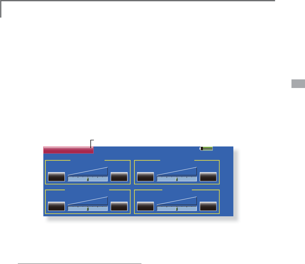
Music pla
y
back
7KH70=WUDQVPLWWHUFDQSOD\EDFNWKHZPDPXVLF¿OHVVWRUHGLQWKH6'FDUGDQG86%PHPRU\
You can
li
sten to t
h
em t
h
roug
h
t
h
e
b
u
il
t-
i
n spea
k
er or a
h
ea
d
p
h
one
b
y t
h
e earp
h
one p
l
ug.
[
Im
p
ortant notice]
%HIRUHGRZQORDGLQJ¿OHVIURP\RXU3&LQWRWKH
S
D car
d,
i
nsert t
h
e SD car
d
i
nto t
h
e transm
i
tter
a
nd turn on the power of the transmitter. Then
t
he following folders will be automatically
F
UHDWH
G
L
QW
K
H6'FDU
G
:
K
HQ\RX
G
RZQ
O
RD
G
¿O
HV
IURP
\
RX3&FRS
\
DQGSDVWHWKH¿OHVLQWRWKHL
U
F
RUUHVSRQGLQJ¿OHV
%03SLFWXUHÀOHV
:0$PXVLFÀOHV
:$9VRXQGÀOHV
0
2
'(/PRGHOGDWDÀOHV
3XVKWKH0XVLF3OD
\
EDFNEXWWRQRQWKHKRPH
VFUHHQWRFDOOWKHIROORZLQ
J
VHWXSVFUHHQ
5
H
W
X
UQW
R
WK
H
K
R
P
H
VF
U
HHQ
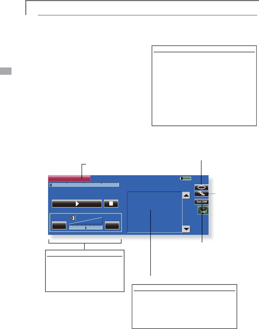
%XWWRQWRVHOHFWHLWKHU
2
QHWLPH
3OD
\
EDFNRU5H
S
HDW3OD
\
EDF
N
%
X
WW
R
QW
R
VH
O
HF
W
H
LWK
HU
2
QH0XVLF
3OD
\
EDFNR
U
0XOWL
S
OH0XVLF
3OD
\
EDF
N
6
:VHOHFWLRQEXWWR
Q
3XVKWKLVEXWWRQWRFDOOWKH
6
:
VH
O
HF
W
VF
U
HH
Q
D
Q
G
F
K
RRVH
WK
H
0XVLF
S
OD
\
EDFNVZLWFK
5HIHUWRWKHGHVFULSWLRQLQWKH
HQGRIWKLVPDQXDO
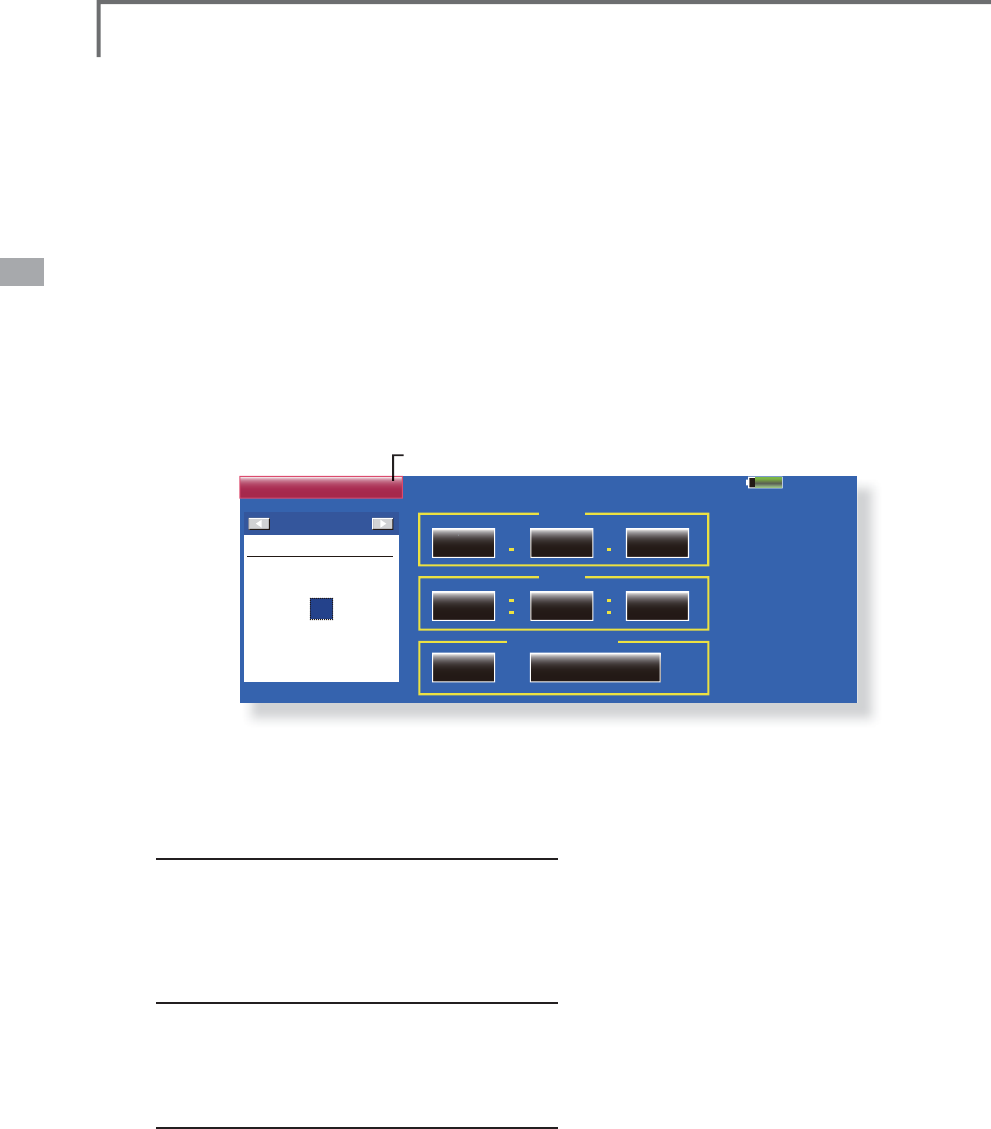
Buttons for music playback
<RXFDQSOD\EDFNDQ\PXV
L
F
IL
OHVO
L
VWHGRQWKHU
L
JKWV
L
GHR
I
W
K
HVFUHHQ
,
I
\RXDG
M
XVWWKHYROXPHKHUH
L
W
DG
M
XVWVQRWRQO\PXV
L
FSOD\EDFN
EXWDOVRRWKHUDSSO
L
FDW
L
RQV
T
o playback
$OOWKHPXV
L
F
À
OHVVDYHG
L
QWKH&)FDUGZ
L
OO
E
HV
K
RZQ
K
HUH
3XVKWKH
IL
OHQDPHWRVHOHFWWKHPXV
L
F
IL
OH
\RXZDQWWR
K
HDU
8VHWKHEXWWRQVRQWKHOH
I
WWRSOD\EDFNR
U
VWRSWKHPXV
L
F
3OD\EDFNÀOHOLVW
Playback File
File not found !
Model 1
85%
00:00:00 / 00:00:00
Sel.SW
Player
-+
Player
51
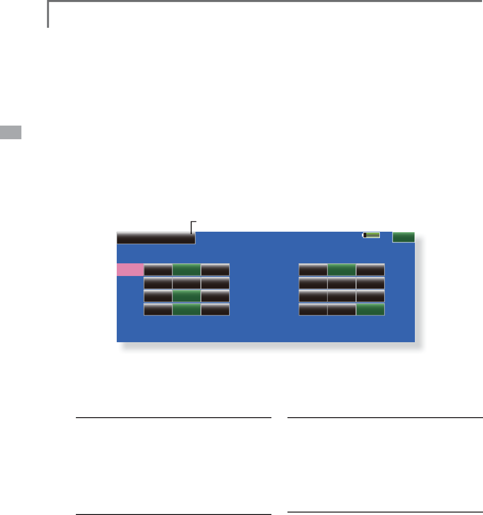
<System Menu>
85%
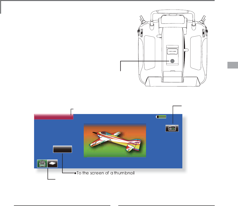
Camera
Thumbnail
Model1
Save to...
Shootin
g
method
7XUQRQWKHWUDQVPLWWHUDQGFDOO
>
&DPHUD
@
I
URPWKH6
\
VWHP0HQX
6HOHFWWKHSLFWXUHVDYHGHVWLQDWLRQ
70=
6
'FDUG86%PHPRU\
*
W
h
en an SD car
d
an
d
USB memor
y
are connecte
d
, an
i
con
i
s
di
sp
l
aye
d
an
d
can
b
e se
l
ecte
d
.
3R
L
QWWKHFDPHUDDWWKHEDFNR
I
WKH
W
UDQVP
L
WWHUWRZDUGWKHVXE
M
HFWDQGSUHVVWKH
VK
XWWHU
E
XWWRQ
7KHS
L
FWXUHFDQEHFKHFNHGZ
L
WKWKH
>
7KXPEQD
L
O@EXWWRQ$S
L
FWXUHFDQEHFRS
L
HG
D
QGGHOHWHGE\SUHVV
L
QJ
L
W
Displa
y
pictures at the model data
&DOO
>
&DPHUD
@
IURPWKH6
\
VWHP0HQX
0DNHWKHVDYHGHVWLQDWLRQWKHVDPH
S
ODFH
D
VPRGHOGDWD,IDQ6'FDUGRU86%PHPRU
\
L
VQRWFRQQHFWHG
WKH70=EHFRPHVWKH
L
QLWL
D
O
V
W
D
W
H
7DNHWKH
S
LFWXUH
\
RXZDQWWRGLV
S
OD
\
ZLWKWKH
7
0=
3RVLWLRQWKHSLFWXUHLQVLGHWKHIUDPH
6HOHFWWKHPRGHOZKRVH
S
LFWXUH
\
RXZDQWWR
S
DVWHEHIRUHKDQG
3UHVV
>
7KXPEQDLO
@
DQGWKHQ
S
UHVVWKH
S
LFWXUH
\
RXWRRNHDUOLHU
3UHVV
>
(QWU
\@
7KHPHVVD
J
H´6XUH"µLVGLVSOD\HG3UHVV><HV@
Camera &DPHUDSKRWR
J
UDSK\DQGSLFWXUHVWRUD
JH
Pictures can be easil
y
taken with the camera
i
n t
h
e T18MZ. T
h
e
pi
cture can
b
e save
d
to t
h
e
T
18MZ, SD car
d
, an
d
USB memor
y
. Your favor
i
te
model photo
g
raphed b
y
y
ou can be displa
y
ed on
th
e Home screen
,
Start screen
,
an
d
Mo
d
e
l
Se
l
ect
screen.
ŏ&DOOWKH
I
ROORZ
L
QJVHWW
L
QJVFUHHQE\SUHVV
L
QJWKH
>&DPHUD@EXWWRQ
L
QWKH6\VWHP0HQX
ŏ5HWXUQWR
6
\VWHP0HQ
X
ŏ3
L
FWXUHGDWDVDYHGHVW
L
QDW
L
RQ
70=6'FDUG86%PHPRU\
7R
WKH
VFUHHQ
RI
D
WKXPEQDLO
ŏVKX
WW
H
U
EX
WW
R
Q
Camera
52 <System Menu>
85%
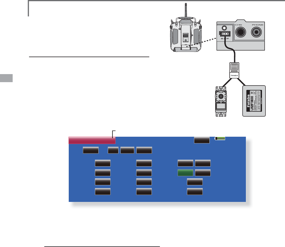
S.BUS Servo
Servo
Type
Soft
Start
Stop
Mode
NORM
Recall
Reverse
Neutral
2íVHW
Dead
Band
Boost
+0.00
0.03
0.0
Smoother
Speed
Control
Trave l
Adjust
Damper
Factor
Stretcher
Gain
100.0
ACT 12.00
0
0.00
1CH 0 0 INHID
Model 1
100.0
NORM
FREE
OFF
OFF
Procedure for chan
g
in
g
S.BUS servo settin
g
6HOHFW
>
6%866HUYR
@
RIWKH6
\
VWHP0HQX
:LUHWKHVHUYRDVVKRZQLQWKHÀ
J
XUHDERYH
3UHVV>5HFDOO@7KH,'DQGFXUUHQWVHWWLQ
J
RI
W
KDWVHUYRDUHGLV
S
OD
\
HG
:KHQPXOWLSOHVHUYRVDUHFRQQHFWHGFKDQ
J
H
>
,1+@DWWKHUL
J
KWVLGHRIWKH,'QXPEHURQWKH
V
FUHHQWR
>
$&7
@
DQGHQWHUWKH,'RIWKHVHUYR
\
RXZDQWWRVHW
6HWHDFKLWHP
3OHDVHVHHWKHQH[WSD
J
H
3UHVV>:ULWH@7KHVHWWLQ
J
VDUHFKDQ
J
HG
S.BUS Servo 6%86VHUYRVHWWLQ
J
An
S
.B
US
servo can memorize the channel
an
d
var
i
ous sett
i
ngs
i
tse
l
f. Servo sett
i
ng
can be
p
erformed on the T18MZ screen
b
y wiring the servo as shown in the figure.
ŏ
&DOOWKHIROORZLQ
J
VHWWLQ
J
VFUHHQE\SUHVVLQ
J
WKH
>
6%866HUYR
@
EXWWRQLQWKH6
\
VWHP0HQX
ŏ
5HWXUQWR6
\
VWHP0HQX
HUB
or Y-adapter
S.BUS servo Receiver Battery
Ɣ
6
HUYR,'QXPEH
U
I
n
di
v
id
ua
l
ID num
b
ers are memor
i
ze
d
at t
h
e
S
.B
US
servos. W
h
en one servo
i
s set as s
h
own at t
h
e r
igh
t,
t
he servo ID number is automaticall
y
read. However,
w
h
en you
d
o not want to c
h
ange one sett
i
ng of
m
u
l
t
i
p
l
e servos mounte
d
to t
h
e fuse
l
a
g
e, on
ly
t
h
e
desired servo in the multi-connection state can be set
b
y enter
i
ng t
h
e ID of t
h
at servo.

53
<System Menu>
S.BUS Servo Description of function of each parameter
,'
Displays the ID of the servo whose parameters are to be read. It cannot be changed.
&KDQQHO
Channel of the S.BUS system assigned to the servo. Always assign a channel before use.
5HYHUVH
The direction in which the servo rotates can be changed.
6HUYRW\SH
When “Retractable” is selected and the servo has been continuously stopped for 30 seconds, the dead band
expands and unnecessary hold current due to external force is eliminated. When a new control signal enters,
normal operation is resumed. When using the servo as a landing gear servo, select “Retractable”. Also adjust the
servo travel to match the landing gear movement range.
6RIW6WDUW
Restricts operation in the specified direction the instant the power is turned on. By making this setting, only the
first operation when the power is turned on slowly moves the servo to the specified position.
6WRS0RGH
The state of the servo when the servo input signal is lost can be specified. The "Hold" mode setting holds the
servo in its last commanded position even if using AM or FM system.
6PRRWKHU
This function changes smoothness of the servo operation relative to operation signal changes. Normally use at
Smooth setting. Especially, select the "OFF" mode when quick operation is necessary.
1HXWUDO2IIVHW
The neutral position can be changed. When the neutral offset is large value, the servo's range of travel is restricted
on one side.
6SHHG&RQWURO
Speeds can be matched by specifying the operating speed. The speed of multiple servos can be matched without
being affected by motor fluctuations. This is effective for load torques below the maximum torque.
However, note that the maximum speed will not be exceeded even if a speed over the maximum speed of the
servo at each operating voltage is set.
'HDGEDQG
The dead band angle at stopping can be specified.
[Relationship between dead band set value and servo operation]
Small ĺ Dead band angle is small and the servo is immediately operated by a small signal change.
Large ĺ Dead band angle is large and the servo does not operate at small signal changes.
(Note) If the dead band angle is too small, the servo will operate continuously and the current consumption will
increase and the life of the servo will be shortened.
7UDYHO$GMXVW
The left and right travels centered about the neutral position can be set independently.
%RRVW
The minimum current applied to the internal motor when starting the servo can be set. Since a small travel does
not start the motor, it essentially feels like the dead band was expanded. The motor can be immediately started by
adjusting the minimum current which can start the motor.
[Relationship between boost set value and servo operation]
Small ĺ Motor reacts to a minute current and operation becomes smooth.
Large ĺ Initial response improves and output torque increases. However, if the torque is too large, operation will
become rough.
'DPSHU
The characteristic when the servo is stopped can be set.
When smaller than the standard value, the characteristic becomes an overshoot characteristic. If the value is
larger than the standard value, the brake is applied before the stop position.

54 <System Menu>
Especially, when a large load is applied, overshoot, etc. are suppressed by inertia and hunting may occur,
depending on the conditions. If hunting (phenomena which cause the servo to oscillate) occurs even though the
Dead Band, Stretcher, Boost and other parameters are suitable, adjust this parameter to a value larger than the
initial value.
[Relationship between damper set value and servo operation]
Small ĺ When you want to overshoot. Set so that hunting does not occur.
Large ĺ When you want to operate so that braking is not applied. However, it will feel like the servo response has
worsened.
(Note) If used in the hunting state, not only will the current consumption increase, but the life of the servo will also
be shortened.
6WUHWFKHU
The servo hold characteristic can be set.
The torque which attempts to return the servo to the target position when the current
servo position has deviated from the target position can be adjusted.
This is used when stopping hunting, etc., but the holding characteristic changes as shown below.
[Relationship between stretcher and servo operation]
Small ĺ Servo holding force becomes weaker.
Large ĺ Servo holding force becomes stronger.
(Note) When this parameter is large, the current consumption increases.

55
<System Menu>
Model 1 85%
Information
Version
WindowsCE Ver. 6.0 (0)
Editor Ver. 0.1.0
Encoder
English
Ver. 0.1
Memory Size 0 MB
Free Space 0 MB
Model data 0 model
0 MB
0 MB
0 model
SD Card
Language
USB Memory
Product ID
Area
000000000
America
Information
7
KHSUR
J
UDPYHUVLRQ&)FDUG86%PHPRU\GDWDDQGSURGXFW,'DUHGLVSOD\HG
7
KHODQ
J
XD
J
HXVHGE\WKHV\VWHPFDQDOVREHFKDQ
J
HG
The Information screen displa
y
s the T18MZ
system program vers
i
on
i
nformat
i
on, T18MZ
,SD car
d
an
d
USB memor
y
(
memor
y
s
i
ze, vacant
capacit
y
, number of model data, and number of
PXV
L
F
¿O
HV
L
QIRUPDW
L
RQDQ
G
SUR
G
XFW,'
The language (Japanese, English) used on the
screen can a
l
so
b
e c
h
ange
d
.
ŏ7RXFKWKH
>
,QIRUPDWLRQ
@
EXWWRQDWWKH6
\
VWHP
0HQXWRFDOOWKHVHWX
S
VFUHHQVKRZQEHORZ
ŏ5HWXUQWR6
\
VWHP0HQ
X
*
When an SD card and USB memory are not inserted, thei
r
information is not displayed.
ŏ
6HOHFWDEOHIRU/DQ
J
XD
J
H
56 <System Menu>
Range Check %HIRUHDÁL
J
KW
J
URXQGUDQ
J
HFKHFN
T
he 'ran
g
e check mode' reduces the transmission
r
ange of t
h
e ra
di
o waves to a
ll
ow for a groun
d
r
an
g
e c
h
ec
k
.
*
T
h
e range c
h
ec
k
mo
d
e, w
h
en act
i
vate
d
, w
ill
cont
i
nue for
90 seconds unless the user exits this mode early. When the
progress bar reaches 90s, the RF transmission automatically
returns to the normal operatin
g
power.
ŏ
3XVKWKH
>
6
@
.H
\
→
7
XUQ
2
1WKHWUDQVPLWWHUV
S
RZHUVZLWFK
[
12@LVSXVKHG
ŏ
[
<HV@LVSXVKHG
W
arn
i
ng
Do not f
ly
i
n t
h
e ran
g
e c
h
ec
k
mo
d
e.
*
S
i
nce t
h
e range of t
h
e ra
di
o waves
i
s s
h
ort,
i
f t
h
e
mo
d
e
l
i
s too far from t
h
e transm
i
tter
,
contro
l
w
ill
be
l
os
t an
d
th
e
m
ode
l
w
ill
c
ra
s
h
.
Rotat
i
on Ran
g
e
C
heck method
3XVKWKH
>
6
@
.H
\
→
7XUQ
2
1WKHWUDQVPLWWHUV
S
RZHUVZLWFK6HOHFW
>
1R
@
*For safety, the RANGE CHECK mode can not be selected
while the RF transmission is active.
,QW
K
HV\VWHPPHQXF
K
RRVHW
K
H
5DQ
J
H
&
KHFNVHOHFW
L
RQ
I
URPWKHPHQXR
S
W
L
RQV
7KH5DQ
J
H&KHFNVFUHHQ
L
VG
L
VSOD\HG7R
D
FW
L
YDWHWKH5DQ
J
H&KHFNPRGHSUHVV
WKH><HV@EXWWRQ'XU
L
Q
J
WKH5DQ
J
H&KHFN
S
HU
L
RGWKH5)
S
RZHU
L
VUHGXFHGWRDOORZWKH
J
URXQGUDQ
J
HWHVWVWREHSHU
I
RUPHG
7KH5DQ
J
H&KHFN
I
XQFW
L
RQDXWRPDW
L
FDOO\
H[
L
WVD
I
WHUWKH
VHFRQGW
L
PHO
L
P
L
WKDV
H[S
L
UHG7KHSUR
J
UHVVEDU
L
VG
L
VSOD\HGRQWKH
WUDQVP
L
WWHUVVFUHHQ6KRXOG
\
RXFRP
S
OHWH
WKHUDQ
J
HFKHFNEH
I
RUHWKHVHFRQGVKDV
S
UHVVHG
S
UHVVWKH
>
([
L
W
@
EXWWRQ
*
W
h
en t
h
e [RESTART]
b
otton
i
s presse
d
, t
h
e range c
h
ec
k
mode
t
i
m
e
r
is
r
e
t
u
rn
ed
t
o
0
.
*
P
l
ease note, upon exp
i
rat
i
on of t
h
e 90 secon
d
s, or
when
[
Exit
]
is selected, the transmitter will
automatically return to the normal RF operation as
noted on the display.
*
Once t
h
e 18MZ
i
s transm
i
tt
i
ng at fu
ll
power,
i
t
i
s
not poss
ibl
e to enter t
h
e Ran
g
e C
h
ec
k
mo
d
e
ZLWKRXW¿UVWVZLWFKLQ
J
WKHWUDQVPLWWHU2IIDQG
back On. This has been designed to prevent a
P
R
G
H
O
HUIURP
L
QD
G
YHUWHQW
O
\
À
\
L
QJ
L
QW
K
H5DQJ
H
Ch
ec
k
mo
d
e.
:KHQWKH>([LW@EXWWRQLVSUHVVHGWKH5DQ
J
H
&
KHFNPRGHLVGLVDEOHGDQGWKH
0=ZLOO
E
H
J
LQ
WUDQVPLWWLQ
J
DWIXOOSRZHU
*
After ex
i
t
i
n
g
t
h
e Ran
g
e C
h
ec
k
mo
d
e, t
h
e
funct
i
on cannot
b
e se
l
ecte
d
a
g
a
i
n. To se
l
ect t
h
e
R
an
g
e Check mode a
g
ain
y
ou must c
y
cle the
transmitter
p
ower switch.
ŏ7RXFKWKH>5DQ
J
H&KHFN@EXWWRQDWWKH6\VWHP
0HQXWRFDOOWKHVHWX
S
VFUHHQVKRZQEHORZ
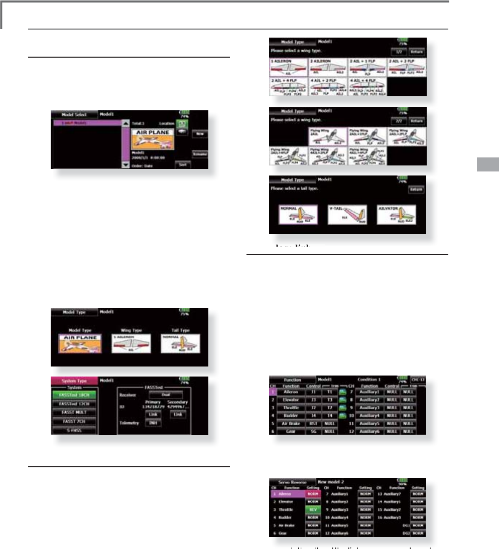
57
<Model Basic Setting Procedure>
MODEL BASIC SETTING PROCEDURE
1
. Model add
i
t
i
on and call
In
i
t
i
a
l
sett
i
ng ass
i
gns 1 mo
d
e
l
to t
h
e T18MZ
transmitter. The Model Select function of the
Linkage Menu is used to add models and to call
mo
d
e
l
s w
hi
c
h
are a
l
rea
d
y set.
T
his is convenient when callin
g
a model after its
name has been registered. (Data can also be saved to
t
h
e accessory SD car
d
an
d
USB memory
)
T
he currently called model name is displayed at the
top of t
h
e screen. Before f
l
y
i
ng an
d
b
efore c
h
ang
i
n
g
DQ
\
VHWWLQ
J
VDOZD
\
VFRQ¿UPWKHPRGHOQDPH
W
h
en a new mo
d
e
l
was a
dd
e
d
, t
h
e Mo
d
e
l
t
y
pe
s
elect screen/S
y
stem mode/Receiver link automaticall
y
appear. P
l
ease
b
e aware t
h
at t
h
e transm
i
tter w
ill
s
top transm
i
tt
i
n
g
w
h
en
y
ou c
h
an
g
e t
h
e mo
d
e
l
.
2
. Model t
y
pe selection
Select the model t
y
pe matched to the fusela
g
e wit
h
the Model Type select function of the Linkage Menu.
For an a
i
rp
l
ane, se
l
ect t
h
e mo
d
e
l
type from among t
h
e
3
t
y
pes: airplane,
g
lider, and motor
g
lider. When the
W
ing type select screen is displayed and the wing type
i
s se
l
ecte
d
w
h
en se
l
ect
i
ng t
h
e mo
d
e
l
type, t
h
e Ta
il
type
s
elect screen is displa
y
ed. Select the tail t
y
pe matched
to the fuselage.
T
here are 13 win
g
t
y
pes and 3 tail t
y
pes for airplane,
glid
er, an
d
motor g
lid
er
.
Airplane/
g
lider basic settin
g
procedure
3. Fuselage linkage
Li
n
k
t
h
e a
il
erons
,
e
l
evators
,
t
h
rott
l
e
,
ru
dd
er
,
etc.
i
n accor
d
ance w
i
t
h
t
h
e mo
d
e
l
's
i
nstruct
i
on manua
l
.
For a descri
p
tion of the connection method, see the
Rece
i
ver an
d
S
ervos
C
onnect
i
on.
Note: The channel assignment of the T18MZ is
d
ifferent from that of our existing systems. Note
t
hat even for the same "air
p
lane model", when the
win
g
type and tail type are different, the channel
a
ssignment may be different.
(
The channel assigned
t
o each
f
unct
i
on can be checked at the Funct
i
on
menu of the Linkage Menu.
)
ŏ:KHQWKHGLUHFWLRQRIWKHOLQND
J
HLVUHYHUVHG
DG
M
XVWWKHGLUHFWLRQZLWKWKH5HYHUVHIXQFWLRQRI
WKH/LQND
J
H0HQX
ŏ&RQQHFWWKHWKURWWOHOLQNDJHVRFDUEXUHWRULV
RSHQDW
I
XOOWU
L
PDQG
I
XOORSHQWKHQWKHWKURWWOH
FDQ
E
HFXW
ŏ$G
M
XVWWKHQHXWUDOSRV
L
W
L
RQDQGUXGGHUDQJOH
Z
L
WKWKHO
L
QNDJHDQG
IL
QHWXQHWKHPZ
L
WK
WKH6XE7U
L
PDQG(QG3R
L
QW
I
XQFW
L
RQV
UXGGH
U
DQJOHDG
M
XVWPHQW
7RSURWHFWWKHO
L
QNDJHD
O
L
P
L
WSRV
L
W
L
RQFDQDOVREHVHWZ
L
WKWKH(QG3R
L
QW
I
XQFW
L
RQ7KH(QG3R
L
QW
I
XQFW
L
RQFDQDG
M
XVWWKH
DPRXQWR
I
XSGRZQDQGOH
I
WU
L
JKWPRYHPHQW
O
L
P
L
WDQGVHUYRVSHHGR
I
HDFKFKDQQHO
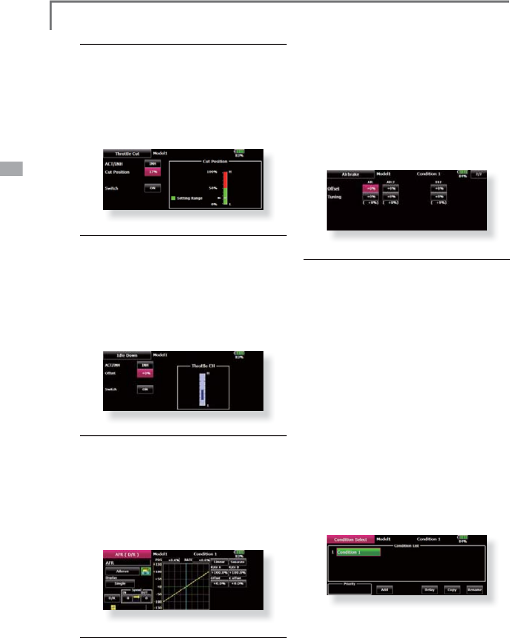
58 <Model Basic Setting Procedure>
4
. Throttle cut sett
i
n
g
Th
rott
l
e cut can
b
e performe
d
w
i
t
h
one touc
h
b
y
a
switch without chan
g
in
g
the throttle trim position.
Set throttle cut with the Throttle Cut function o
f
the Linka
g
e Menu. After activatin
g
the throttle cut
funct
i
on an
d
se
l
ect
i
ng t
h
e sw
i
tc
h
, a
dj
ust t
h
e t
h
rott
l
e
p
osition so that the carburetor becomes full open. Fo
r
safet
y
, the throttle cut function operates the throttle
st
i
c
k
i
n t
h
e s
l
ow pos
i
t
i
on
.
5
. Idle down setting
T
he idlin
g
speed can be lowered with one touch b
y
a sw
i
tc
h
w
i
t
h
out c
h
ang
i
ng t
h
e t
h
rott
l
e tr
i
m pos
i
t
i
on.
P
erform this settin
g
with the Idle Down function of th
e
Linka
g
e Menu. After activatin
g
the Idle Down function
an
d
se
l
ect
i
ng t
h
e sw
i
tc
h
, a
dj
ust t
h
e
idl
e
d
own spee
d
.
F
or safet
y
, the idle down function acts onl
y
when the
throttle stick is in the slow
p
osition
.
*
W
hil
e t
h
e T
h
rott
l
e Cut funct
i
on
i
s
i
n operat
i
on, t
h
e I
dl
e
D
ow
n f
u
n
c
ti
o
n
does
n
o
t
wo
rk
.
6. AFR
(
D
/
R
)
AFR funct
i
on
i
s use
d
to a
dj
ust t
h
e t
h
row an
d
operation curve of the stick, lever, and switch functions
for each flight condition. This is normally used afte
r
En
d
Po
i
nt
(
ATV
)
h
as
d
ef
i
ne
d
t
h
e max
i
mum t
h
row
d
irections (End Point acts on ALL fli
g
ht condition
settings). When mixing is applied from one channel to
anot
h
er c
h
anne
l
,
b
ot
h
c
h
anne
l
s can
b
e a
dj
uste
d
at t
h
e
same time b
y
ad
j
ustin
g
the operation rate throu
g
h th
e
AFR function
.
7
. A
i
rbrake
Thi
s funct
i
on
i
s use
d
w
h
en an a
i
r
b
ra
k
e
i
s necessary
w
hen takin
g
off or divin
g
, etc
.
T
he
p
reset elevators and fla
p
s (camber fla
p
, brake
À
DS
RIIVHWDPRXQWFDQ
E
HDFW
L
YDWH
G
E
\DVZ
L
WF
K
7
KHRIIVHWDPRXQWRIWKHDLOHURQHOHYDWRUDQGÀD
S
servos can
b
e a
dj
uste
d
as nee
d
e
d
. A
l
so t
h
e spee
d
of t
he
D
LO
HURQH
O
HYDWRUDQ
G
À
DSVHUYRVFDQ
E
HD
GM
XVWH
G
,1
side/OUT side) A delay can be set for each condition,
an
d
a Cut sw
i
tc
h
w
hi
c
h
w
ill
turn OFF t
h
e
d
e
l
ay can
E
HF
K
RVHQ7U
L
PDPRXQWVFDQ
E
H
¿
QHWXQH
G
E\
VHWW
L
Q
J
a VR You can also set the Auto Mode, which will lin
k
A
i
r
b
ra
k
e to a st
i
c
k
, sw
i
tc
h
, or
di
a
l
. A separate st
i
c
k
VZ
L
WF
K
RU
GL
D
O
FDQD
O
VR
E
HVHWDVW
K
H21
2))VZ
L
WF
K
$GGLWLRQRIÀL
J
KWFRQGLWLRQ
V
The transmitter can install up to ei
g
ht fli
g
ht
c
onditions per model. You can assign all switches
i
nc
l
u
di
ng st
i
c
k
s, sw
i
tc
h
es, tr
i
m
l
evers an
d
tr
im
VZLWFKHVDVÀL
J
KWFRQGLWLRQVHOHFWLRQVZLWFKHV<R
X
c
an also add delayed mixing to these functions in
o
r
d
er to avo
id
su
dd
en c
h
anges. Moreover, you ca
n
VHWSULRULW
\
RUGHUIRUÀL
J
KWFRQGLWLRQVZKHQ
\
RXVH
W
more than one condition. In addition, you can copy
c
on
di
t
i
ons an
d/
or c
h
ange names of con
di
t
i
ons. T
hi
s
F
RPPDQGPD
\
DOVREHXVHGWRGH¿QHZKDWVZLWFKHV
a
nd/or controls are used to activate each fligh
t
co
n
di
t
io
n
.
T
h
e Con
di
t
i
on Se
l
ect funct
i
on automat
i
ca
ll
y
all
ocates t
h
e Con
di
t
i
on 1 for eac
h
mo
d
e
l
t
y
pe.
Condition 1 is the default condition, also referred to
D
V1RUPD
O
DQ
G
L
VW
K
HRQ
O
\RQHDFW
L
YHZ
K
HQDQHZ
PR
G
H
O
W
\
SH
L
V
G
H
¿
QH
G
7
KL
VFRQ
GL
W
L
RQ
L
VD
O
ZD
\
VRQ
a
nd remains on until other conditions are activate
d
b
y sw
i
tc
h
es
.
The Condition Delay can be programmed for each
ch
anne
l
. T
h
e Con
di
t
i
on De
l
ay
i
s use
d
to c
h
ange t
h
e
servo throw smoothl
y
when switchin
g
conditions.
*When a new condition is added
,
"Condition1" data is
automatically copied.
*S
e
l
ect t
h
e con
di
t
i
on sw
i
tc
h
an
d
set t
h
e new con
di
t
i
on
d
ata
i
n t
he
VZLWFK21VWDWH+RZHYHULIWKHJURXSPRGH*UZDVVHOHFWHGL
Q
advance, the same data will be in
p
ut at all the conditions. Select the
sin
g
le mode (Sn
g
l) and ad
j
ust the condition
y
ou want to chan
g
e
.
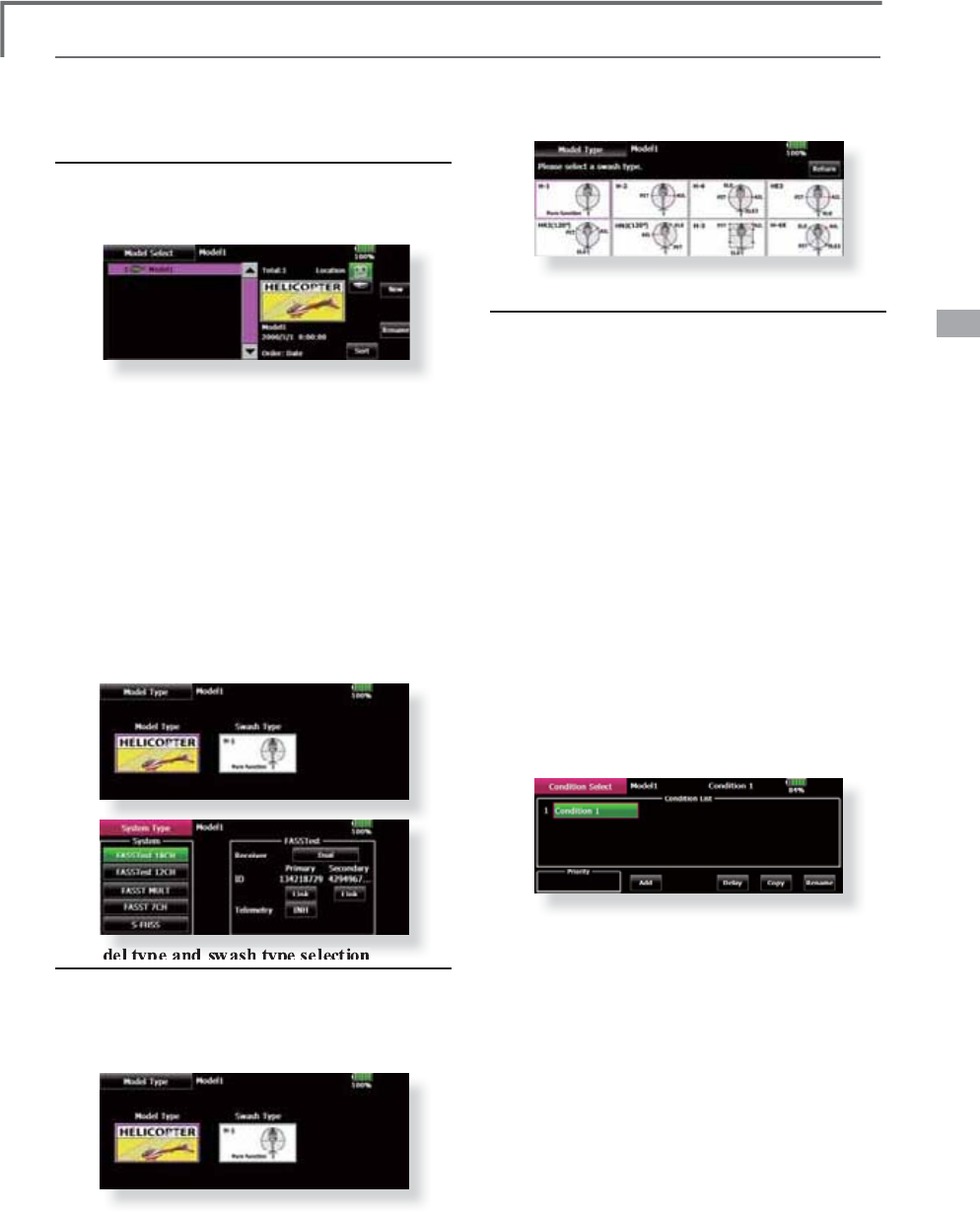
59
<Model Basic Setting Procedure>
1. Model addition and call
D
efault settin
g
assi
g
ns 1 model to the T18MZ. To
a
dd
new mo
d
e
l
s or to ca
ll
a mo
d
e
l
a
l
rea
d
y set, use t
h
e
Mo
d
e
l
Se
l
ect funct
i
on of t
h
e L
i
n
k
a
g
e Menu.
This is convenient when callin
g
a model after
reg
i
ster
i
ng t
h
e mo
d
e
l
names
i
n a
d
vance.
(
Data can a
l
so
b
e save
d
to t
h
e accessor
y
SD car
d
an
d
USB memor
y)
T
h
e current
l
y ca
ll
e
d
mo
d
e
l
i
s
di
sp
l
aye
d
at t
h
e top
R
IW
K
HVFUHHQ%HIRUH
À\L
Q
J
DQ
G
E
HIRUHF
K
DQ
JL
Q
J
DQ
\
VHWWLQJVDOZD\VFRQ¿UPWKHPRGHOQDPH
P
lease be aware that the transmitter will sto
p
t
ransmitting when you change the model.
W
hen a new model was added, the Model t
y
pe select
s
creen
/
System mo
d
e
/
Rece
i
ver
li
n
k
automat
i
ca
lly
appear. P
l
ease
b
e aware t
h
at t
h
e transm
i
tter w
ill
s
top transmittin
g
when
y
ou chan
g
e the model.
2. Model type and swash type selection
W
h
en a separate mo
d
e
l
type
i
s a
l
rea
d
y se
l
ecte
d
,
se
l
ect
h
e
li
copter w
i
t
h
t
h
e Mo
d
e
l
T
y
pe funct
i
on of t
h
e
L
inka
g
e Menu, and then select the swash t
y
pe matche
d
t
o t
h
e fuse
l
age.
H
elicopter basic settin
g
procedure
3. Flight condition addition
The transmitter can install up to eight fligh
t
co
n
di
t
i
ons per mo
d
e
l
. You can ass
i
gn a
ll
sw
i
tc
h
es
i
ncludin
g
sticks, switches, trim levers and trim switches
DVI
OLJK
WFRQ
GL
W
L
RQVH
O
HFW
L
RQVZ
L
WF
K
HV<RXFDQD
O
VR
a
dd
d
e
l
aye
d
m
i
x
i
ng to t
h
ese funct
i
ons
i
n or
d
er to
avoid sudden changes. Moreover, you can set priority
RUGHUIRUÀL
J
KWFRQGLWLRQVZKHQ
\
RXVHWPRUHWKDQRQH
con
di
t
i
on. In a
ddi
t
i
on,
y
ou can cop
y
con
di
t
i
ons an
d/
o
r
c
h
ange names of con
di
t
i
ons. T
hi
s comman
d
may a
l
so
be
used
t
o
de
f
i
n
e
wh
at
swi
t
ches
an
d/o
r
co
ntr
ols
ar
e
X
VHGWRDFWLYDWHHDFKÀLJKWFRQGLWLRQ
T
h
e Con
di
t
i
on Se
l
ect funct
i
on automat
i
ca
ll
y a
ll
ocates
t
he Condition 0 for each model type. Condition 0 is
W
KHGHIDXOWFRQGLWLRQDOVRUHIHUUHGWRDV1RUPDODQGLV
WK
HRQ
O\
RQHDFW
L
YHZ
K
HQDQHZPR
G
H
O
W
\
SH
L
V
G
H
¿
QH
G
Thi
s con
di
t
i
on
i
s a
l
ways on, an
d
rema
i
ns on unt
il
ot
h
e
r
conditions are activated by switches.
T
h
e Con
di
t
i
on De
l
ay can
b
e programme
d
for eac
h
channel. The Condition Delay is used to change th
e
s
ervo throw smoothl
y
when switchin
g
conditions
.
*
HQHUDO
ÀLJ
KWFRQG
L
W
L
RQVHWW
L
Q
J
H[DPSOH
ŏ1RUPDO
8VHLQLWLDOVHWWLQ
J
FRQGLWLRQVRSHUDWH
ZKHQVZLWFK2))
8VHIURPHQJLQHVWDUWLQJWRKRYHULQJ
ŏ,GOHXS
6ZLWFKVHWWLQ
J
H[DPSOH2SHUDWH
DW6:(FHQWHU
8VHLQVWDOOWXUQORRSUROOLQ
J
VWDOOWXUQDQGRWKH
U
PDQH
XY
HUV
ŏ,GOHXS
6Z
L
WFKVHWW
L
QJH[DPSOH2SHUDWH
DW6:(
I
RUZDUGV
L
GH
8VH
L
QUROOV
ŏ7KURWWOHKROG
6ZLWFKVHWWLQ
J
H[DPSOH
2SHUDWHDW6:*IRUZDUGVLGH
8VHLQDXWRURWDWLRQ
T
h
e pr
i
or
i
ty
i
s t
h
rott
l
e
h
o
ld/idl
e up 2
/idl
e up 1
/
norma
l
. T
h
rott
l
e
h
o
ld
h
as t
h
e
high
est pr
i
or
i
t
y
.
Add
ot
h
er con
di
t
i
ons, as re
q
u
i
re
d
.
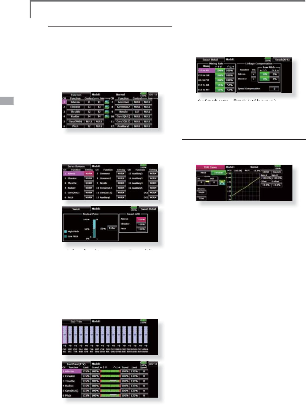
60 <Model Basic Setting Procedure>
ŏ6ZDVKSODWHFRUUHFWLRQ
([FHSW+PRGH
2
SHUDW
L
RQR
I
WKHVZDVKSODWHQHDUWKHKRYHU
L
QJ
S
RLQWFDQEHFRUUHFWHGE
\
VZDVK$)5IXQFWLRQ
FRUUHFWLRQPL[LQJ8VHWKLVZKHQSLWFKDLOHURQ
DQGHOHYDWRUR
S
HUDWLRQFDXVHVWKHVZDVK
S
ODWHWR
GHYLDWHIURPWKHQRUPDOGLUHFWLRQ
&DOOWKH6ZDVKVHWXSĺ6ZDVKGHWDLOVVFUHHQ
3
L
WFKVORZV
L
GHDQGK
L
JKV
L
GHO
L
QNDJHFRUUHFW
L
RQ
L
V
DOVRSRVV
L
EOH$G
M
XVWVRWKDWS
L
WFKRSHUDW
L
RQFDXVHV
WKHVZDVK
S
ODWHWRPRYHX
S
DQGGRZQLQWKH
K
RUL]RQWDOVWDWH
5
. Throttle curve setting
This function adjusts the pitch operation curve
i
n r
el
at
io
n t
o
t
he
m
ove
m
e
nt
o
f t
he
t
h
r
o
tt
le
s
t
ick
f
o
r
each condition.
(17
p
oints curve)
The pitch curve can be freel
y
selected from linea
r
o
perat
i
on curve to smoot
h
curve, an
d
a
dj
uste
d
to
matc
h
t
h
e curve
y
ou want
by
means of t
h
e T18MZ’s
powerful Curve Edit Function (6 t
y
pes of curves can
b
e se
l
ecte
d)
. Up to 17 po
i
nts can
b
e set for
li
nea
r
R
UFXUYHW
\
SHV+RZHYHUZ
K
HQXV
L
Q
J
W
K
HSR
L
QWV
R
U
S
RLQWVV
S
HFL¿HGWRFUHDWHDFXUYHDVLP
S
OHDQ
G
smoot
h
curve can
b
e create
d
b
y se
l
ect
i
ng t
h
e curve
t
y
pe an
d
re
d
uc
i
n
g
t
h
e num
b
er of
i
nput po
i
nts to 3
o
r 5, and then enterin
g
the specified value at the
c
orrespon
di
ng po
i
nts t
h
at you create
d.
6
HWW
L
Q
J
H[DPSOH!
Ca
ll
t
h
e t
h
rott
l
e curve of eac
h
con
di
t
i
on w
i
t
h
t
h
e
c
ondition select switch.
ŏ1RUPDOFXUYHDG
M
XVWPHQW
1RUPDOFXUYHXVHV1RUPDO/LQHDUW\SHDQGFUHDWHV
DEDVLFSLWFKFXUYHFHQWHUHGQHDUKRYHULQJ7KLV
FXUYHLVDG
M
XVWHGWR
J
HWKHUZLWKWKH7KURWWOH&XUYH
1RUPDO
VRWKDWWKHHQ
J
LQHVSHHGLVFRQVWDQWDQG
XSGRZQFRQWURO
L
VHDV
L
HVW
ŏ,GOHXSFXUYHDG
M
XVWPHQW
7KHK
LJ
KV
L
GHS
L
WFKFXUYHVHWVWKHPD[
L
PXPS
L
WFK
UHJDUGOHVVR
I
WKHHQJ
L
QHORDG7KHORZV
L
GHS
L
WFK
FX
UY
H
F
U
HD
W
HV
D
FX
UY
H
P
D
W
F
K
HG
IR
U
DH
U
RED
W
LFV
ORRSUROO'HWF
1RWH:
K
HQW
K
HFXUYHW\SH
L
VF
K
DQJH
G
W
K
H
G
DWD
L
VUHVHW
4
. Fusela
g
e linka
g
e
Connect the throttle rudder, ailerons, elevators,
p
itch, and other rudder linkages in accordance with
t
h
e
ki
t
i
nstruct
i
on manua
l
. For a
d
escr
i
pt
i
on of
the connection method, see "Receiver and Servos
C
onnection".
7KHFKDQQHODVVL
J
QPHQWRIWKH70=LV
GLIIHUHQWIURPWKDWRIRXUH[LVWLQJV\VWHPV7K
H
c
hannel assigned to each function can be checke
d
D
WWKH)XQFWLRQPHQXRIWKH/LQNDJH0HQX
ŏ:KHQWKHG
L
UHFW
L
RQR
I
RSHUDW
L
RQR
I
WKH
O
L
QNDJH
L
VUHYHUVHXVHWKH5HYHUVH
I
XQFW
L
RQ
R
I
WKH/
L
QNDJH0HQX$OVRXVHWKHVZDVK$)5
I
XQFW
L
RQ
L
QRWKHUWKDQWKH+PRGH
ŏ$GMXVWWKHGLUHFWLRQRIRSHUDWLRQRIWKHJ\UR
*\URVLGHIXQFWLRQ
ŏ&RQQHFWWKHWKURWWOHOLQND
J
HVRWKDWWKH
FDUEXUHWRUEHFRPHVIXOOR
S
HQDWIXOOWULP
WKURWWOHFXWLV
S
RVVLEOH
ŏ%DVLFDOO\DG
M
XVWWKHQHXWUDOSRVLWLRQDQG
UXGGHUDQ
J
OHDWWKHOLQND
J
HVLGHDQGILQH
WXQHZLWKWKH
6
XE7ULPIXQFWLRQDQG(QG
3RLQWIXQFWLRQ
UXGGHUDQ
J
OHDG
M
XVWPHQW
7R
SURWHFWWKHOLQND
J
HDOLPLWSRVLWLRQFDQDOVR
EH
VH
WZLWKWK
H
(Q
G
3
R
LQWI
X
Q
F
WL
R
Q

61
<Model Basic Setting Procedure>
&RQÀUPWKDWWKHUDWHRIWKHVORZHVWSRVLWLRQRI
W
KHVWLFNLVLQLWLDOVHWWLQJ
%
HVXUHWKDWZKHQVHWWRKLJKVLGHWKHFXUYH
RIDQ
\
FRQGLWLRQGRHVQRWH[FHHG
Example of pitch curve settin
g
:
&DOOWKH
S
LWFKFXUYHRIHDFKFRQGLWLRQZLWK
W
K
H
FR
Q
G
LWL
R
Q
VH
O
HF
W
V
ZLW
F
K
*
Pitch curve graph display can be switched to pitch angle
d
irect readin
g
displa
y
.
$
3LWFKFXUYH
1RUPDO
0DNHWKHSLWFKDWKRYHULQ
J
DSSUR[LPDWHO\
º
~
6
º
6
HWWKHSLWFKDWKRYHULQ
J
ZLWKWKHVWLFNSRVLWLRQDW
W
KH
SRLQWDVWKHVWDQGDUG
*
Stabilit
y
at hoverin
g
ma
y
be connected to the throttle curve.
Adj
ustment
i
s eas
y
by
us
i
n
g
t
h
e
h
over
i
n
g
t
h
rott
l
e funct
i
on
a
n
d
h
over
i
n
g
p
i
tc
h
funct
i
on to
g
et
h
er.
%
3LWFKFXUYH
,GOHXS
7
KHLGOHX
S
S
LWFKFXUYHIXQFWLRQFUHDWHVDFXUYH
P
DWFKHGWRDLUERUQHÁLJKW
6
HWWR
º
a
º
DVVWDQ
G
DU
G
&
3
L
WFKFXUYH
,GOHXS
7
KHKL
J
KVLGHSLWFKVHWWLQ
J
LVOHVVWKDQLGOHXS
7
KHVWDQGDUG
L
V
º
'
3
L
WFKFXUYH
+ROG
$
WDXWRURWDW
L
RQXVHWKHPD[
L
PXPS
L
WFKDWERWK
W
KHK
L
JKDQGORZV
L
GHV
>
3
L
WFKDQJOHVHWW
L
QJH[DPSOH
@
7K
URWW
O
H
K
R
OG
º
a
º
6
. Throttle hold sett
i
n
g
&
D
OO
W
K
H7
K
URWW
O
H+R
OG
IXQFW
L
RQIURPW
K
H0R
G
H
O
Menu and switch to the throttle hold condition with
t
he condition select switch.
1RWH$WLQLWLDOVHWWLQJWKHVHWWLQJPRGHLVWKH
JURXSPRGH6
L
QFHWK
L
V
I
XQFW
L
RQ
L
VQRWXVHGDWRWKH
U
FRQGLWLRQVVZLWFKWRWKHVLQJOHPRGHEHIRUHVHWWLQJ
ŏ
6HWWLQ
J
WRWKHVWDWHZKLFKDFWLYDWHVWKH
IX
Q
F
WL
R
Q
7
KHWKURWWOHKROGIXQFWLRQDOORZVVHWWLQ
J
IRUWKURWWOH
FXWDQGVZLWFKLQ
J
RIWKHIXQFWLRQÀ[HGDWWKHLGOH
SRV
L
W
L
RQE\VZ
L
WFK
I
RUWUD
L
Q
L
Q
J
(
L
WKHURQHRUERWK
I
XQFW
L
RQVFDQEHSHU
I
RUPHG
ŏ
+ROGSRVLWLRQVHWWLQJ
7
K
L
V
I
XQFW
L
RQVHWVWKHVHUYRR
S
HUDW
L
RQ
S
RV
L
W
L
RQDW
W
KURWWOHKROG
7KURWWOHFXWDQG
L
GOHSRV
L
W
L
RQV
ŏ
2WKHUVHWWLQ
J
V
:KHQ
\
RXZDQWWROLQNR
S
HUDWLRQZLWKVWLFN
P
DQLSXODWLRQWKH$XWRPRGHFDQEHVHW
:KHQ\RXZDQWWRDG
M
XVWWKHVHUYRVSHHGDG
M
XVW
>6SHHG@
3
L
WFKWR58'P
L
[
L
Q
J
VHWW
L
Q
J
Use t
hi
s funct
i
on w
h
en you want to suppress
t
he torque
g
enerated b
y
the chan
g
es in the pitch
and speed of the main rotor during pitch operation.
A
dj
ust
i
t so t
h
at t
h
e nose
d
oes not sw
i
ng
i
n t
h
e
UXGGHUGLUHFWLRQ+RZHYHUZKHQXVLQ
J
DKHDGLQ
J
hold gyro like those shown below, do not use Pitch
t
o RUD m
i
x
i
ng.
1
RWH:KHQXVLQ
J
D*<*<*<*<
R
URWKHUKHDG
L
Q
J
KROG
J
\URWK
L
V3
L
WFKWR58'
PL
[
L
Q
J
VKRXOGQRWEHXVHG7KHUHDFW
L
RQWRUTXH
L
V
F
RUUHFWHGDWWKHJ\URV
L
GH:KHQRSHUDW
L
QJWKH
J
\UR
L
QWKH$9&6PRGHWKHP
L
[HGV
L
JQDOZ
L
OOFDXVH
Q
HXWUDOGHY
L
DW
L
RQV\PSWRPVDQGWKHJ\URZ
L
OOQRW
RS
HUDWHQRUPD
OO\
Ca
ll
t
h
e P
i
tc
h
to RUD m
i
x
i
n
g
funct
i
on from t
h
e
Model Menu, and set the curve for each condition.
$W
L
Q
L
W
L
D
O
VHWW
L
QJW
KL
VIXQFW
L
RQ
L
V
L
QW
K
H,1+
VWDWH7RXVH
L
WVHW
L
WWRW
K
H21VWDWH
(
17 po
i
nts curve
)
Curve setting of up to 17 points is possible.
+RZHYHU
L
QW
K
HIR
OO
RZ
L
QJVHWW
L
QJH[DPS
O
HD
simple curve can be ad
j
usted b
y
usin
g
the [Linear]
curve
t
ype.
1
RWH$WLQLWLDOVHWWLQJWKHVHWWLQJPRGHLVWKHJURXS
P
RGH,QWKLVPRGHWKHVDPHFRQWHQWVDUHVHWDWLQ
D
OOFRQGLWLRQV:KHQ\RXZDQWWRVHWWKHVHOHFWHG
F
RQGLWLRQRQO\VZLWFKWRWKHVLQ
J
OHPRGH
6HWWLQ
J
H[DPSOH
!
C
all the mixin
g
curve of each condition with the
co
n
d
iti
o
n
se
l
ec
t
sw
it
c
h
.
ŏ
7KURWWOHKROGFXUYHDG
M
XVWPHQW
7
KHWKURWWOHKROGFXUYHLVXVHGZKHQSHUIRUPLQ
J
D
XWRURWDW
L
RQG
L
YHV
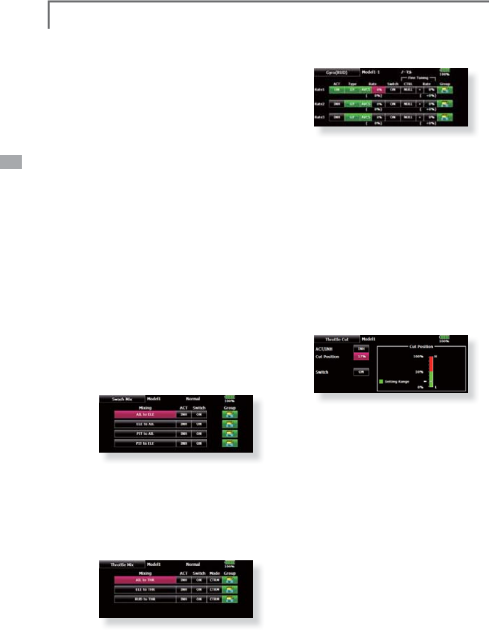
62 <Model Basic Setting Procedure>
$FXUYHVHWWLQ
J
H[DPSOHLVVKRZQEHORZ
$3LWFKWR58'PL[LQJFXUYH
1RUPDO
8
VHWKHKRYHU
L
QJV\VWHPDQGVHWWK
L
VFXUYHWR
PDWFKWDNHRIIDQGODQGLQJDQGYHUWLFDOFOLPEDW
DFRQVWDQWV
S
HH
G
*For this curve, use the initial setting [Linear] curve type and
adjust the left and right rates in the [Separate] mode.
%3
L
WFKWR58'P
L
[
L
QJ
,GOHXS
8
VHWK
L
VFXUYH
L
Q
º
VWDOOWXUQORRSDQGUROO
L
Q
J
V
WDOOWXUQDQGDG
M
XVW
L
WVRWKH
I
XVHOD
J
H
L
V
I
DF
L
Q
J
V
WUD
L
JKWDKHDGZKHQKHDG
L
QJ
L
QWRWKHZ
L
QG
*
For t
hi
s curve, [L
i
near] curve t
y
pe can
b
e use
d
an
d
t
h
e ent
i
re
curve can
b
e
l
owere
d
w
i
t
h
t
h
e [Offset]
b
utton.
&3LWFKWR58'PL[LQ
J
+ROG
7KLVIXQFWLRQLVVHWVRWKDWWKHIXVHODJHLVIDFLQJ
V
WUDL
J
KWDKHDGDWVWUDL
J
KWOLQHDXWRURWDWLRQ7KH
SLWFKRIWKHWDLOURWRUEHFRPHVQHDUO\
º
*For this curve, [Linear] curve t
y
pe can be used and the entire
curve can be lowered with the
[
Offset
]
button.
ŏ2WKHUVHWW
L
QJ
V
7KHP
L
[
L
Q
J
U
L
VHFKDUDFWHU
L
VW
L
FDWS
L
WFKRSHUDW
L
RQ
FDQEHDG
M
XVWHG$QDFFHOHUDW
L
RQ
$&/5
I
XQFW
L
RQ
ZK
L
FKWHP
S
RUDU
L
O
\
L
QFUHDVHDQGGHFUHDVHWKH
PL[LQJDPRXQWFDQEHVHW
6
ZDVK0
L
[FRUUHFWVD
L
OHURQHOHYDWRUDQG
p
itch interaction
T
he swash mix function is used to correct the
swas
h
p
l
ate
i
n t
h
e a
il
eron
(
ro
ll)
di
rect
i
on an
d
e
l
evator
(
c
y
c
li
c p
i
tc
h)
correspon
di
n
g
to eac
h
o
p
eration of each condition.
7KURWWOHP
L
[
L
Q
J
VHWW
L
Q
J
RPM
l
oss cause
d
b
y swas
h
operat
i
on at a
il
eron
or elevator o
p
eration can be corrected with the
7KU
R
WWO
H
0L[I
X
Q
F
WL
R
Q
R
IWK
H
0
RGH
O0
H
Q
X
+
RZ
c
l
oc
k
w
i
se an
d
counterc
l
oc
k
w
i
se torque
i
s app
li
e
d
w
hen pirouettin
g
can also be corrected.
*\URVHQVLWLYLW\DQGPRGHVZLWFKLQ
J
T
he
gy
ro sensitivit
y
and mode switchin
g
function is dedicated gyro mixing of the Model
Menu
,
an
d
can
b
e set for eac
h
con
di
t
i
on.
ŏ1RUPDOFRQGLWLRQ
KRYHULQ
J
*\URVHQVLWLYLW\
P
D
[LP
X
P
ŏ,GOHX
S
,GOHX
S
7KURWWOHKROG*
\
UR
V
HQVLWLYLW
\
PLQLPXP
ŏ+RZHYHU
DWDXWRURWDWLRQRIDWDLOGULYHQ
KHOLFR
S
WHUWKLVIXQFWLRQPD
\
QRWKDYHDQ
\
DIIHFWDWKL
J
K
J
\URVHQVLWLYLW\
11. Throttle cut setting
Throttle cut provides an eas
y
wa
y
to stop the
HQJ
L
QH
E
\
ÀL
SS
L
QJDVZ
L
WF
K
Z
L
W
K
W
K
HW
K
URWW
O
HVW
L
F
N
a
t
idl
e. T
h
e act
i
on
i
s not funct
i
ona
l
at
high
t
h
rott
l
e
to avoid accidental dead sticks. The switch’s
l
ocat
i
on an
d
di
rect
i
on must
b
e c
h
osen
,
as
i
t
d
efau
l
ts
WR18//
*
W
i
t
h
t
h
rott
l
e st
i
c
k
at
idl
e, a
dj
ust t
h
e cut pos
i
t
i
on
unt
il
t
h
e eng
i
ne cons
i
stent
l
y s
h
uts off,
b
ut t
h
rott
l
e
linka
g
e is not bindin
g
. When finished, touch the
“
T
h
rott
l
e
C
ut”
b
utton to ex
i
t.
2WKHUVSHFLDOPL[LQ
J
V
ŏ3LWFKWR1HHGOHPL[LQ
J
7KLVPL[LQJLVXVHGZLWKHQJLQHVZLWKDFRQVWUXFWLRQ
ZKLFKDOORZVQHHGOHFRQWUROGXULQ
J
ÁL
J
KW
IXHODLU
PL[WXUHDG
M
XVWPHQW
$QHHGOHFXUYHFDQEHVHW
7KHQHHGOHVHUYRU
L
VHFKDUDFWHU
L
VW
L
FVDWWKURWWOH
VW
L
FNDFFHOHUDW
L
RQGHFHOHUDW
L
RQRSHUDW
L
RQFDQEH
DG
M
XVWHG
$FFHOHUDW
L
RQ
I
XQFW
L
RQ
ŏ)
XH
OPL[W
X
U
H
I
X
Q
F
WL
R
Q
7KLVPL[LQJLVXVHGLQQHHGOHDGMXVWPHQWRIHQJLQHV
ZKL
F
K
XVH
D
I
XH
OPL[W
X
U
H
FR
QWU
R
O
FD
U
EX
U
H
W
R
U
ŏ*RYHUQRUPL[LQ
J
7KLVPL[LQJLVGHGLFDWHGJRYHUQRUPL[LQJZKHQD
J
RYHUQRULVXVHG8SWRUDWHV
VSHHGV
FDQEH
VZLWFKHGIRUHDFKFRQGLWLRQ
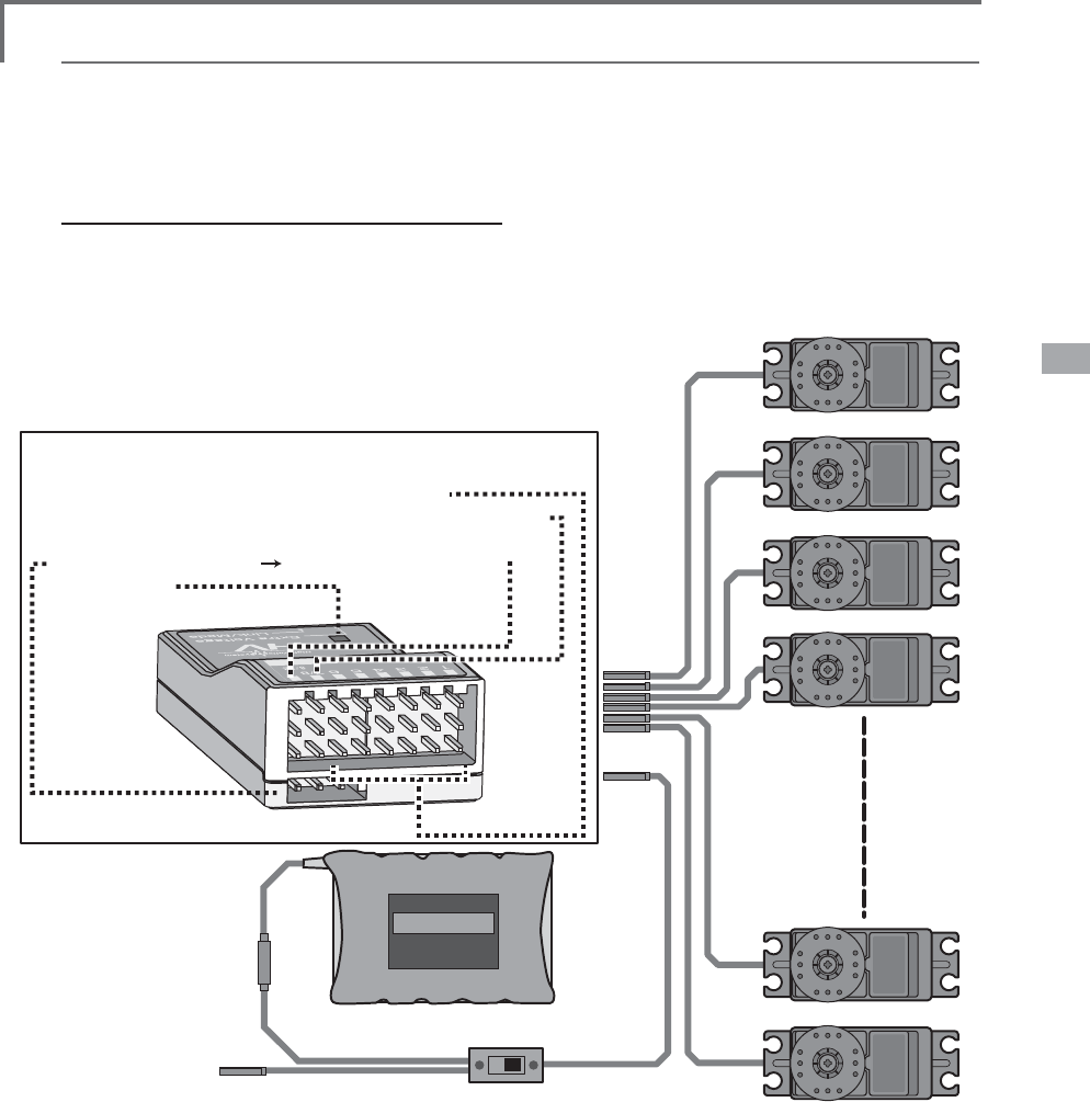
63
<Model Basic Setting Procedure>
Receiver switch
Receiver battery
Charging port/
DSC connector
In S.BUS
use
(8/SB)
S.BUS not
using it
(CH1-8)
(7/B)
Servos
Ɣ$OZD\VFRQQHFWWKHQHFHVVDU\QXPEHURIVHUYRV
Ɣ7KHUHFHLYHUFKDQQHODVVLJQPHQWGHSHQGVRQWKH
PRGHOW\SH6HHWKH6HUYRFRQQHFWLRQE\PRGHO
W\SHWDEOHV
56%RXWSXWFRQQHFWRUVHFWLRQ
5HFHLYHUFRQQHFWRUV
Ɣa2XWSXWIRUFRQYHQWLRQDOV\VWHP&+a
Ɣ%2XWSXWIRUFRQYHQWLRQDOV\VWHP&+3RZHUVXSSO\
Ɣ6%2XWSXWIRUFRQYHQWLRQDOV\VWHP&+RU6%86SRUW
Ɣ6%866%86SRUW
Ɣ0RQLWRU/('
7HOHPHWU\VHQVRUHWF
5HFHLYHUDQGVHUYRVFRQQHFWLRQGLDJUDP
Receiver and servos connection
Connect the receiver and servos in accordance with the connection diagram shown below. Always read
[Precautions when mounting the receiver and servos] of [Before using]. When mounting the receiver and
servos to the fuselage, connect the necessary points in accordance with the kit instruction manual.
Ɣ7KH6HUYRFRQQHFWLRQE\PRGHOW\SHWDEOHVDUHVKRZQRQWKHIROORZLQJSDJHV
Connect the servos to match the fuselage used.

64 <Model Basic Setting Procedure>
6HUYRFRQQHFWLRQE\PRGHOW\SH
The T18MZ transmitter channels are automatically assigned for optimal combination according to the
type selected with the Model Type function of the Linkage Menu. The channel assignment (initial setting)
for each model type is shown below. Connect the receiver and servos to match the type used.
*The set channels can be checked at the Function screen of the Linkage Menu. The channel assignments can also be changed. For
more information, read the description of the Function menu.
$LUSODQHJOLGHUPRWRUJOLGHU
Ɣ$LUSODQHDQG9WDLO
RX CH
1AIL 2AIL 2AIL+1FLAP 2AIL+2FLAP
Airplane Glider Airplane Glider Airplane Glider Airplane Glider
EP EP EP EP
1
2
3
4
5
6
7
8
9
10
11
12
13
14
15
16
DG1
DG2
RX CH
2AIL+4FLAP 4AIL+2FLAP 4AIL+4FLAP
Airplane Glider Airplane Glider Airplane Glider
EP EP EP
1
2
3
4
5
6
7
8
9
10
11
12
13
14
15
16
DG1
DG2

65
<Model Basic Setting Procedure>
RX CH
1AIL 2AIL 2AIL+1FLAP 2AIL+2FLAP
Airplane Glider Airplane Glider Airplane Glider Airplane Glider
EP EP EP EP
1
2
3
4
5
6
7
8
9
10
11
12
13
14
15
16
DG1
DG2
RX CH
2AIL+4FLAP 4AIL+2FLAP 4AIL+4FLAP
Airplane Glider Airplane Glider Airplane Glider
EP EP EP
1
2
3
4
5
6
7
8
9
10
11
12
13
14
15
16
DG1
DG2
Ɣ$LOHYDWRU

66 <Model Basic Setting Procedure>
Ɣ7DLOOHVVZLQJ
RX CH
2AIL 2AIL+1FLAP 2AIL+2FLAP
Airplane Glider Airplane Glider Airplane Glider
EP EP EP
1
2
3
4
5
6
7
8
9
10
11
12
13
14
15
16
DG1
DG2
RX CH
2AIL+4FLAP 4AIL+2FLAP 4AIL+4FLAP
Airplane Glider Airplane Glider Airplane Glider
EP EP EP
1
2
3
4
5
6
7
8
9
10
11
12
13
14
15
16
DG1
DG2

67
<Model Basic Setting Procedure>
Ɣ7DLOOHVVZLQJ:LQJOHW5XGGHU
RX CH
2AIL 2AIL+1FLAP 2AIL+2FLAP
Airplane Glider Airplane Glider Airplane Glider
EP EP EP
1
2
3
4
5
6
7
8
9
10
11
12
13
14
15
16
DG1
DG2
RX CH
2AIL+4FLAP 4AIL+2FLAP 4AIL+4FLAP
Airplane Glider Airplane Glider Airplane Glider
EP EP EP
1
2
3
4
5
6
7
8
9
10
11
12
13
14
15
16
DG1
DG2

68 <Model Basic Setting Procedure>
CH
H-4/H-4X Swash
All Other
1
2
3
4
5
6
7
8
9
10
11
12
13
14
15
16
DG1
DG2
CH
H-4/H-4X Swash
All Other
1
2
3
4
5
6
7
8
9
10
11
12
13
14
15
16
DG1
DG2
Helicopter
Ɣ)$667HVW&+)$66708/7,)$667&+6)+66
Ɣ)$667HVW&+
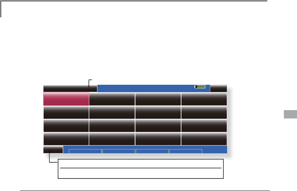
69
<Linkage Menu>
FUNCTIONS OF LINKAGE MENU
System Menu
--Condition Hold
Linkage Menu Model Menu Cond.Hold
Model 1 Normal 85%
Linkage Menu
Model Select Model Type Picture
System Type Function Sub-Trim
Fail Safe Throttle Cut
Timer
Swash Ring Swash
Sound
Servo Monitor
Servo Reverse
Idle Down
INH
End Point(ATV)
1/2
T
he Linka
g
e Menu is made up of functions
whi
c
h
perform mo
d
e
l
a
ddi
t
i
on, mo
d
e
l
type
s
e
l
ect
i
on, frequenc
y
sett
i
n
g
, en
d
po
i
nt sett
i
n
g
, an
d
other model basic settin
g
s.
ŏ5H
W
XUQ
W
R+RPHVFUHH
Q
ŏ:KHQDEXWWRQ
L
QWKH/
L
QNDJH0HQXR
I
WKH+RPHVFUHHQ
LVWRXFKHGWKHPHQXVKRZQEHORZLVFDOOHG7RXFKWKH
EXWWRQRIWKHIXQFWLRQ\RXZDQWWRVHW
T
he functions which can be selected de
p
end on
t
h
e mo
d
e
l
type. A typ
i
ca
l
menu screen
i
s s
h
own
b
e
l
ow.
Linka
g
e Menu functions table
[Servo Monitor]: Displa
y
s the servo test and operation position
[Mo
d
e
l
Se
l
ect]: Mo
d
e
l
a
ddi
t
i
on, ca
ll
,
d
e
l
et
i
on, cop
y
, mo
d
e
l
name sett
i
n
g
[Mo
d
e
l
Type]: Mo
d
e
l
type, w
i
ng type, sw
i
tc
h
type, etc. se
l
ect
i
on
[Picture]: Picture
p
aste for each model
[Sound]: Sound recordin
g
and pla
y
back
[S
y
stem T
y
pe]: S
y
stem selection, receiver link
[Funct
i
on]: C
h
anne
l
ass
ig
nment of eac
h
funct
i
on can
b
e c
h
an
g
e
d
[Su
b
-Tr
i
m]: A
dj
usts t
h
e neutra
l
pos
i
t
i
on of eac
h
servo
[Servo Reverse]: Servo direction reversal
[Fail Safe]: Fail safe function and batter
y
fail safe function settin
g
[En
d
Po
i
nt
(
ATV
)
]: Servo
b
as
i
c ru
dd
er a
dj
ustment an
d
li
m
i
t sett
i
n
g
[T
h
rott
l
e Cut]: Stops t
h
e eng
i
ne safe
l
y an
d
eas
il
y
(
a
i
rp
l
ane an
d
h
e
li
copter on
l
y
)
[Idle Down]: Lowers the idle speed of the engine (airplane and helicopter only)
[Swash Rin
g
]: Limits the decline of the swash plate to prevent linka
g
e dama
g
e (helicopter onl
y
)
[Swash]: Swash AFR and linka
g
e correction function (helicopter onl
y
)
[T
i
mer]: T
i
mer sett
i
ng an
d
l
ap t
i
me
di
sp
l
ay
[D
i
a
l
Mon
i
tor]: D
i
a
l
, s
lidi
ng
l
ever, an
d
di
g
i
ta
l
tr
i
m pos
i
t
i
on
di
sp
l
ay
[Function Name]: Function Name can be changed
[Telemetr
y
]: Displa
y
s various data sent from the receiver.
[Sensor]: Var
i
ous te
l
emetr
y
sensors sett
i
n
g
[Warn
i
ng]: Sett
i
ng of warn
i
ng soun
d
an
d
v
ib
rat
i
on
[Data Reset]: Model memory set data reset (by item)
C
ondition Hold function
ON/O
FF button
)
RUDGHWD
L
OHGGHVFU
L
SW
L
RQVHHS
&RQG
L
W
L
RQ+ROG
I
XQFW
L
RQ
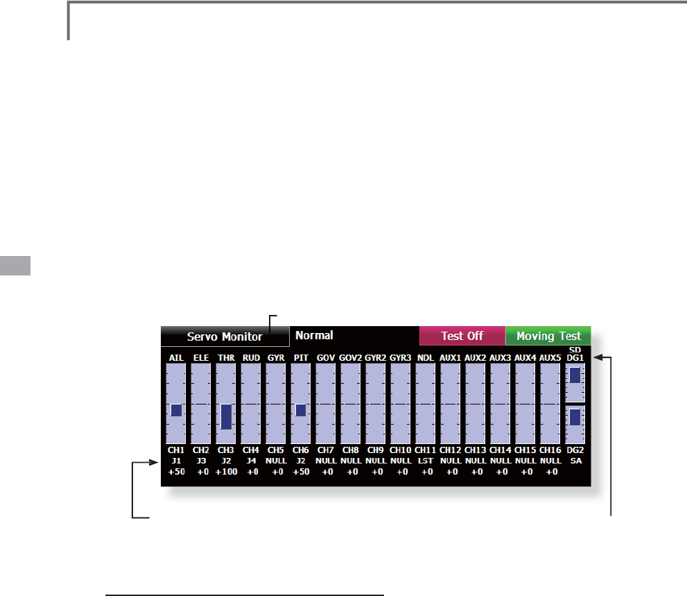
70 <Linkage Menu>
Servo Monitor 6HUYR7HVW*UD
S
K'LV
S
OD
\
'LV
S
OD
\
VVHUYR
S
RVLWLRQV
T
his is used for testin
g
servo movement. Touch
“Mov
i
ng Test”
(
repet
i
t
i
on mo
d
e
)
or “Neutra
l
T
est”
(
f
i
xe
d
pos
i
t
i
on mo
d
e
)
d
epen
di
n
g
on w
hi
c
h
one shows on the screen. To
g
et from one to the
ot
h
er, s
i
mp
l
y touc
h
t
h
e f
i
e
ld
aga
i
n, an
d
you w
ill
ŏ
5HWXUQWR/LQNDJH0HQX
ŏ
7RXFKWKH>6HUYR0RQLWRU@EXWWRQLQWKH/LQND
J
H0HQX
W
RFDOOWKHVHWX
S
VFUHHQVKRZQEHORZ
move from “Movin
g
Test” to “Neutral Test”
automat
i
ca
ll
y. Next touc
h
t
h
e “Test” on
/
off
b
utton
t
o start test
i
n
g
y
our servos. T
h
e “Neutra
l
test”
i
s
g
ood for findin
g
the neutral position of a servo
ho
rn
.
S
ervo test operat
i
on
6HOHFWDWHVWPRGH
>0RY
L
QJ@RU>1HXWUDO@
>
5H
S
HDW
@
(DFKVHUYRUH
S
HDWVR
S
HUDW
L
RQ
>
1HXWUDO
@
(DFKVHUYR
L
VORFNHG
L
QWKHQHXWUDO
S
RVLWLRQ
:KHQWKH>7HVW2II@EXWWRQLVWRXFKHGWHVWLQ
J
E
H
J
LQVLQWKHVHOHFWHGPRGH
&
RQWUROQDPH
)X
Q
F
WL
R
QQ
D
P
H
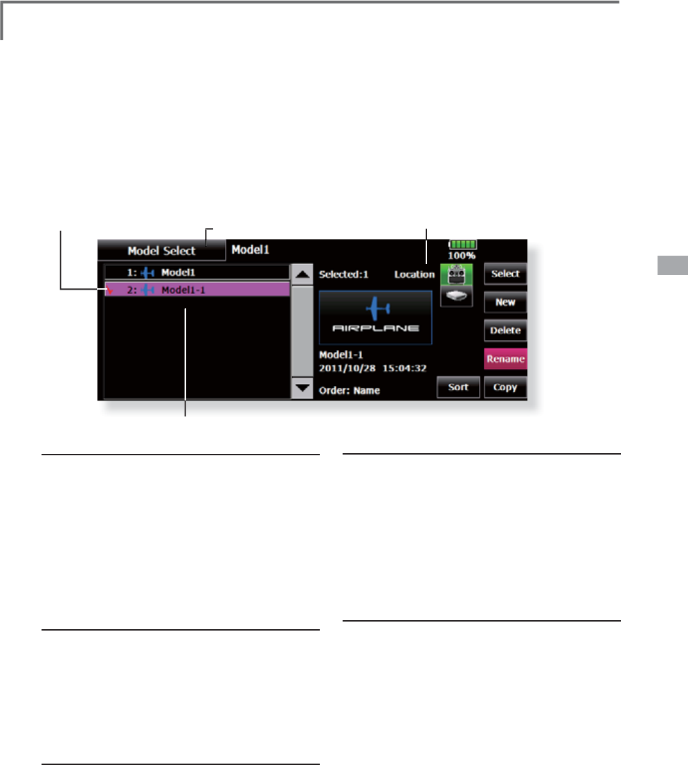
71
<Linkage Menu>
ŏ5HWXUQWR/LQND
J
H0HQ
X
ŏ
&
KHFNPDU
N
ŏ7RXFKWKH>0RGHO6HOHFW@EXWWRQLQWKH/LQND
J
H0HQXWRFDOOWKHVHWXSVFUHHQVKRZQEHORZ
Model Select
7
KH0RGHO6HOHFWLRQIXQFWLRQ
S
HUIRUPVPRGHODGGLWLRQFDOOGHOHWLRQFR
S\
DQGPRGHOQDPHVHWWLQ
J
T
hi
s funct
i
on
i
s use
d
to
l
oa
d
t
h
e sett
i
ngs of t
he
desired model into the T18MZ’s memor
y.
T
h
e sett
i
ngs may
b
e se
l
ecte
d
from e
i
t
h
er t
h
e
t
ransmitter’s built-in memor
y
or a SD card/USB
m
emory.
The name of the model stored in the transmitter and
th
e SD car
d/
USB memory may
b
e c
h
ange
d
. T
hi
s can
b
e ver
y
usefu
l
to te
ll
di
fferent mo
d
e
l
s sett
i
n
g
s apart.
Each model name can be as lon
g
as 32 characters, and
t
he model name always appears in the display screen.
The Cop
y
function is used to cop
y
one set of mode
l
d
ata
i
nto a secon
d
memory w
i
t
hi
n t
h
e transm
i
tter an
d
th
e SD car
d/
USB memor
y
. It ma
y
b
e use
d
for
g
ett
i
n
g
a
head-start on settin
g
up models with almost the same
VHWW
L
QJV
RQ
O
\
GL
IIHUHQFHVQHH
G
WR
E
HPR
GL¿
H
G
L
QVWHD
G
o
f enter
i
n
g
t
h
e comp
l
ete mo
d
e
l
from scratc
h)
. A
l
so,
t
his function ma
y
be used to make a backup cop
y
of
a
m
o
d
e
l
setup
b
efore any c
h
anges are ma
d
e
.
(The displa
y
screen is an example. The screen depends on the model t
y
pe.)
(
Mo
d
e
l
li
st
)
Model call
7RXFKWKH6DYHWRLFRQ
DQGVHOHFWWKH
O
RFD
WL
R
QW
R
ZKL
F
KWK
H
GHV
LU
HG
P
RGH
OL
V
W
R
EH
VD
Y
HG
7UDQVPLWWHULFRQ7UDQVPLWWHUPHPRU
\
6
'FDUGLFRQ
6
'FDU
G
86%PHPRU\LFRQ86%PHPRU
\
7RXFKWKHGHV
L
UHGPRGHO
L
QWKHPRGHOO
L
VW
7RXF
K
W
K
H
>6
H
O
HFW
@
E
XWWRQ
7RXFK><HV@WRFDOOWKHPRGHO
:KHQ\RX
ZDQWWRFDQFHOPRGHOFDOOSUHVV>1R@
Model addition
7RXFKWKH
>
1HZ
@
EXWWRQ
7RXFK><HV@WRDGGWKHPRGHO
:KHQ\RX
ZDQWWRFDQFHOPRGHODGGLWLRQWRXFK>1R@
*
W
h
en a new mo
d
e
l
i
s a
dd
e
d
, t
h
e Mo
d
e
l
T
y
pe screen are
automat
i
ca
lly
di
sp
l
a
y
e
d
. C
h
ec
k
or c
h
an
g
e t
h
e mo
d
e
l
. If
th
ere are no c
h
anges, touc
h
t
h
e Mo
d
e
l
Type
i
cons.
*
T
h
e a
dd
e
d
mo
d
e
l
i
s
di
sp
l
a
y
e
d
i
n t
h
e mo
d
e
l
li
st.
Model deletion
7RXFKWKH6DYHWRLFRQRUWKHPRGHO
\
RX
ZDQWWRGHOHWHLQWKHPRGHOOLVW
7KHPRGHO
FXUUHQWO\VHOHFWHGFDQQRWEHGHOHWHG
$
F
K
HF
NP
D
UNL
V
D
WW
DF
K
HG
W
R
WK
H
P
RGH
O
7RXFKWKH
>
'HOHWH
@
EXWWRQ
7RXFK><HV@
:KHQ\RXZDQWWRVWRSPRGHO
GHOHWLRQWRXFK>1R@
M
o
d
e
l
name c
h
ange
6HOHFWWKHPRGHOE\WRXFK
L
QJWKH6DYHWR
L
FRQRUWKHGHV
L
UHGPRGHO
L
QWKHPRGHOO
L
VW
:KHQ>&KDQJH1DPH@
L
VWRXFKHGD
N
H\
E
RDU
G
DSSHDUVRQW
K
HVFUHHQ
(QWHUWKHPRGHOQDPH
I
URPWK
L
VNH\ERDUG
*Up to 32 characters can be input at the model name.
Japanese language input is also possible.
(For a detailed descri
p
tion of the in
p
ut method, see "Use
r
Name Re
g
istration/Character Input Method" of the Basic
O
p
eration section.
M
o
d
e
l
cop
y
$PRGHOWRFR
S\
IURPDPRGHOOLVWLV
S
XVKHG
&
KHFNPDUNLVDWWDFKHGWRWKHPRGHODQGD
&RS\EXWWRQLVGLVSOD\HGRQWKHUL
J
KW
7RXFKWKH&R
S\
EXWWRQDQG7RXFKWKH
'HVWLQDWLRQEXWWRQDQGVHOHFWWKHFR
S\
VWRUD
J
HGHVWLQDWLRQ
7UDQVPLWWHURU6'FDUG
86%PHPRU\
7RXFKWKHFHQWHU
>
&R
S\@
EXWWRQ
:KHQ><HV@LVWRXFKHGFRS\LQ
J
LVH[HFXWHG
:KHQ\RXZDQWWRFDQFHOFRS\LQ
J
WRXFK
>1R@
*If there is no model of the same name at the copy
destination, the name of the cop
y
source is saved. If there
is a model of the same name, a number is a
pp
ended to the
e
n
d
of t
h
e mo
d
e
l
name an
d
t
h
e mo
d
e
l
i
s cop
i
e
d
. C
h
an
g
e t
h
e
name
l
ater.
*When the model data was co
p
ied, the model date
data is reset to the date the model was co
p
ied.
ŏ6DYHWR
ŏ
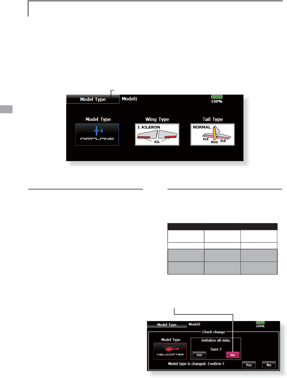
72 <Linkage Menu>
ŏ
5HWXUQWR/LQNDJH0HQX
ŏ
7RXFKWKH>0RGHO7\SH@EXWWRQLQWKH/LQND
J
H0HQXWR
F
DOOWKHVHWX
S
VFUHHQVKRZQEHORZ
ŏ
:KHQGDWDWDNLQ
J
RYHULVSRVVLEOHWKHFRQILUPDWLRQ
V
FUHHQRIGDWDLQLWLDOL]DWLRQLVGLV
S
OD
\
HG
$
S
XVKRQ
>\
HV
@
ZLOOLQLWLDOL]HGDWD
$
S
XVKRQ
>
QR
@
ZLOOVXFFHHGGDWD
Model Type
7
KLVIXQFWLRQVHOHFWVWKHPRGHOW\SHIURPDPRQ
J
DLUSODQHKHOLFRSWHUDQG
J
OLGHU
(
T
h
e
di
sp
l
ay screen
i
s an examp
l
e. T
h
e screen
d
epen
d
s on t
h
e mo
d
e
l
type.
)
Seven t
y
pes of main win
g
s and three t
y
pes
o
f ta
il
w
i
ngs are ava
il
a
bl
e for a
i
rp
l
anes. E
i
g
h
t
swas
h
t
y
pes are ava
il
a
bl
e for
h
e
li
copters. Seven
ty
pes of main win
g
s and three t
y
pes of tail win
g
s
a
re ava
il
a
bl
e for g
lid
ers. Funct
i
ons an
d
m
i
x
i
ng
funct
i
ons necessar
y
for eac
h
mo
d
e
l
t
y
pe are set
i
n
a
dvance at the factor
y
.
1RWH7KH0RGHO7\SH
I
XQFW
L
RQDXWRPDW
L
FDOO\
V
HOHFWVWKHD
SS
UR
S
U
L
DWHRXW
S
XWFKDQQHOVFRQWURO
IXQFWLRQVDQGPL[LQJIXQFWLRQVIRUWKHFKRVHQPRGHO
W\S
H:KHQWKH0RGHO 7
\S
H6HOHFWLRQFRPPDQGLV
D
FFHVVHGDOORIWKH GDWDLQWKHDFWLYHPHPRU
\
LV
FOHDUHG%HVXUHWKDW\RXGRQ·WPLQGORVLQ
J
WKLVGDWD
RUEDFNLWXS WRDQRWKHUPHPRU\XVLQ
J
WKHFRS\LQ
J
I
XQFW
L
RQV
Model type selection
&DOOWKH7\SHVHOHFWVFUHHQE\WRXFK
L
QJWKH
PRGHOW\SHZ
L
QJWD
L
OVZDVKW\SHRURWKHU
W\SH
E
XWWRQ
6
H
O
HFWW
K
HW\SH\RXZDQWWRVHWDQ
G
H[HFXWH
W\SHVHOHFW
L
RQE\WRXFK
L
QJ><HV@DWWKH
FRQ
IL
UPDW
L
RQVFUHHQ
:KHQ\RXZDQWWR
FDQFHOPRGHOW\SHVHOHFW
L
RQWRXFK>1R@
D
ata tak
i
ng over a
f
ter a swash type change
'DWDWDNLQ
J
RYHUPD\EHSRVVLEOHLQWKHVZDVK
W\SHRIDKHOLFRSWHUDWWKHWLPHRIDFKDQJH
5HIHUWRWKHIROORZLQJWDEOH(YHQZKHQLW
VXFFHHGVWKHGDWDRID>VZDVKVHWWLQJ@VFUHHQ
L
V
LQLWL
D
OL]
HG
Before After Data taking over
H
-1
,
H-2
,
HE3
,
H
R3
,
HN3
,
H-3
H
-1
,
H-2
,
HE3
,
H
R3
,
HN3
,
H-3
O
K
+
+;
+
+;
O
K
H
-1
,
H-2
,
HE3
,
H
R3
,
HN3
,
H-3
+
+;
NG
+
+;
H
-1
,
H-2
,
HE3
,
H
R3
,
HN3
,
H-3
NG
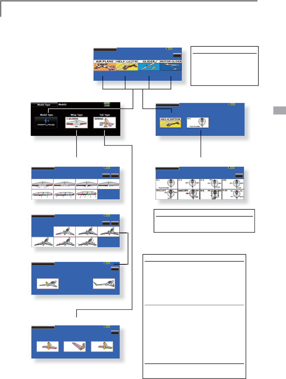
73
<Linkage Menu>
Model 1
Please select model type.
Airplane Helicopter Glider EP Glider
85%
Return
Model Type
Model 1 85%
Model Type
1 AILERON
AIL
2 AILERON
AIL AIL2
2 AIL + 1 FLP
AIL AIL2
FLP
2 AIL + 2 FLP
AIL AIL2
FLP FLP2
2 AIL + 4 FLP
AIL AIL2
FLP
FLP3
FLP4
FLP2
4 AIL + 2 FLP
AIL3
AIL
AIL2
AIL4
FLP
FLP2
4 AIL + 4 FLP
AIL3
AIL
AIL2
AIL4
FLP
FLP3
FLP4
FLP2
Please select a wing type.
Return1/2
Model 1 85%
Model Type
Please select a wing type.
Return2/2
Flying Wing
2AIL+4FLP
AIL AIL2
FLP
FLP3 FLP4
FLP2
Flying Wing
4AIL+2FLP
AIL AIL2
FLP
AIL3 AIL4
FLP2
Flying Wing
4AIL+4FLP
AIL3
AIL
AIL2
AIL4
FLP
FLP3 FLP4
FLP2
Flying Wing
AIL AIL2
2AIL
Flying Wing
AIL AIL2
FLP
2AIL+1FLP
Flying Wing
AIL AIL2
FLP FLP2
2AIL+2FLP
Model 1 85%
Model Type
Please select a Rudder type. Return
Normal Rudder
RUD
Winglet (2RUD)
RUD RUD2
Model 1 85%
Model Type
Please select a tail type. Return
NORMAL
ELE
ELE
RUD
AILVATOR
ELE2
ELE RUD
ELE
RUD
V-TAIL
Model 1 85%
Model Type
Swash TypeModel Type
Model 1 85%
Model Type
Please select a swash type.
Return
M
o
d
e
l
t
y
pe
S
elect the model t
y
pe
f
rom among airplane,
h
e
li
copter, g
lid
er, an
d
motor
g
lider.
ŏ
0RGHOW\SHVHOHFW
L
RQ
(
A
i
rplane, gl
i
der
)
(
Hel
i
copter
)
ŏ
:
L
Q
J
W\SHVHOHFW
L
RQ
ŏ
:
L
Q
J
W\SHVHOHFW
L
RQ
ŏ
5XGGHUW
\S
HVHOHFW
L
RQ
ŏ6ZDVKW
\S
HVHOHFW
L
RQ
ŏ
7D
L
OW
\S
HVHOHFW
L
RQ
W
i
n
g
t
y
pe
(
1
/
2
)
(
Normal
)
Se
l
ect from amon
g
:
D
LO
HURQD
LO
HURQVD
LO
HURQV
À
DS
DLOHURQVÀD
S
VDLOHURQVÀD
S
V
DLOHURQVÀD
S
VDLOHURQVÀD
S
V
Wing type (2/2) (Tailless wing)
S
election from among:
DLOHURQVDLOHURQVÀD
S
DLOHURQVÀDSVDLOHURQVÀDSV
D
LO
HURQV
À
DSVD
LO
HURQV
À
DSV
*
For ta
ill
ess w
i
ng, t
h
e ru
dd
er type can
b
e se
l
ecte
d
f
rom normal rudder and win
g
let.
T
a
i
l type
S
e
l
ect from norma
l,
V ta
il,
an
d
e
l
evator.
H
elicopter swash t
y
pe
6H
O
HFWIURPDPRQ
J
++++(
+5+1+DQG+;

74 <Linkage Menu>
File List
Current File
File not found !
File not found !
Model 1
85%
Thumbnail
Picture
IMG00001
Preview
ŏ7RXFKWKH>3LFWXUH@EXWWRQLQWKH/LQND
J
H0HQXWRFDOO
WKHVHWX
S
VFUHHQVKRZQEHORZ
Picture $SLFWXUHFDQEHSDVWHGIRUHDFKPRGHO
6LPSOLILHVLGHQWLILFDWLRQRIWKHPRGHOGDWD
GXULQ
J
VFUHHQRSHUDWLRQ
A
p
h
otograp
h
of t
h
e mo
d
e
l
ta
k
en w
i
t
h
a T18MZ
c
amera, di
g
ital camera or other file can be paste
d
a
s the screen display data for each model. This is
c
onven
i
ent
i
n
id
ent
i
fy
i
ng mo
d
e
l
s w
i
t
h
t
h
e same
m
odel name.
7KHSLFWXUH¿OHVZKLFKFDQEHGLVSOD\HGRQWKHVFUHHQDUH
size 168 x 80 pixels, file type .bmp (bit map picture)an
d
-3(*¿OHV,ID¿OHODU
J
HUWKDQWKLVLVSDVWHGWKH,WUHGXFHV
o
f the picture is displa
y
ed.
When a picture is pasted, it is displa
y
ed as the
f
ollowing screen image:
ŏ
0R
G
H
O
6
H
O
HFWVFUHHQ
ŏ
+RPHVFUHH
Q
ŏ
6WDUWXSVFUHH
Q
Past
i
ng o
f
p
i
cture
*
P
i
cture
d
ata
i
s paste
d
to t
h
e mo
d
e
l
memory current
l
y
i
n use.
*
T
h
e p
i
cture can c
h
oose on
ly
w
h
at
i
s save
d
i
n t
h
e p
l
ace
(
T18MZ, SD car
d
, USB memor
y)
same now as t
h
e mo
d
e
l
d
ata
u
n
de
r
selec
t
io
n
.
6HOHFWWKH
S
LFWXUHIURPWKH7KXPEQDLOE
\
W
RXFKLQ
J
WKHGHVLUHGSLFWXUHGDWD
*
Before selection, touch the scroll button at the to
p
or bottom
o
f t
h
e T
h
um
b
na
il
an
d
conf
i
rm t
h
e contents of t
h
e
pi
cture
¿O
HVVDYH
G
DWW
K
HSUHY
L
HZVFUHHQ
7RSDVWHWKHS
L
FWXUHWRXFK><HV@
:KHQ\RX
Z
DQWWRFDQFHOSDVW
L
QJWRXFK>1R@
[Important]
B
efore rea
di
ng
d
ata from t
h
e PC,
i
nsert t
h
e
SD card/USB memor
y
into the transmitter and
t
urn on the power. The following folders are
DXWRPDW
L
FD
OO
\ZU
L
WWHQ7RUHD
G
D
¿O
HIURPW
K
H3&
FRS
\
WKH¿OHWRDIROGHUE
\
¿OHW
\
SH
ŏ%033LFWXUHÀOH
ŏ
:$9$XGLRÀO
H
ŏ:0$0XV
L
F
À
O
H
ŏ
0
2
'(/0RGHOGDWD
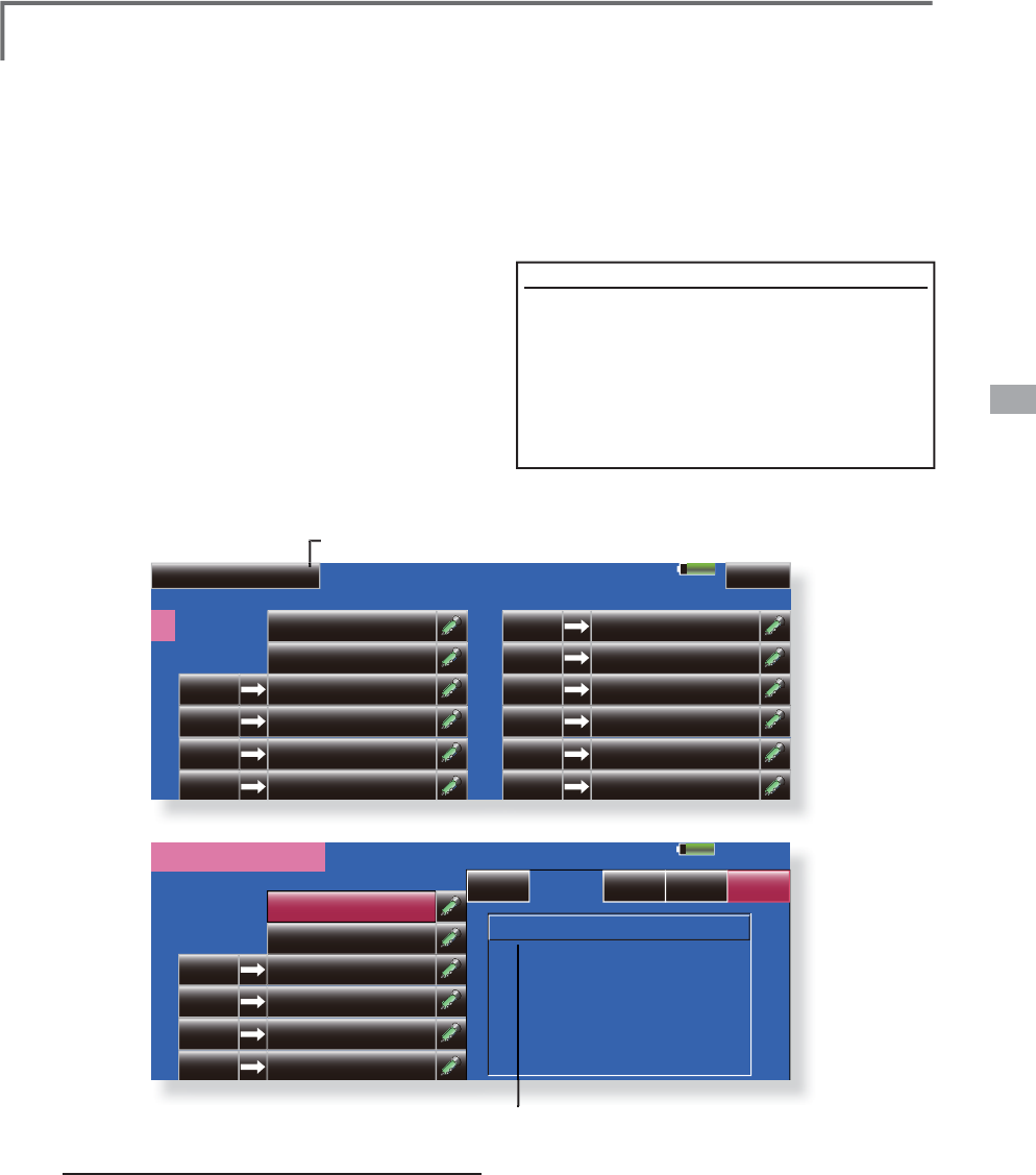
75
<Linkage Menu>
85%
Sound Model1
No Switch Mode
Start up
3RZHURí
2
3
4
5
6
File Rec
1
OFF
OFF
OFF
OFF
No Switch Mode
8
9
10
11
12
File Rec
7
OFF
OFF
OFF
OFF
OFF
OFF
1/2
85%
Model1
No Switch Mode
Start up
01 : test.wav
3RZHURí
2
3
4
5
6
File Rec
1
OFF
OFF
OFF
OFF
Entry CloseRenameDelete
<Sound>
ŏ
5HWXUQWR/
L
QNDJH0HQX
ŏ
7RXFKWKH>6RXQG@EXWWRQLQWKH/LQND
J
H0HQX
W
RFDOOWKHVHWX
S
VFUHHQVKRZQEHORZ
Sound 6RXQGUHFRUGLQ
J
DQGSOD\EDFN
6DYH
G
VRXQ
G
¿O
H
[I
mportant
]
Before rea
di
n
g
d
ata from a PC,
i
nsert t
h
e
S
D card/USB memor
y
into the transmitter an
d
t
urn on t
h
e power. T
h
e fo
ll
ow
i
ng fo
ld
ers are
a
utomat
i
ca
lly
wr
i
tten. W
h
en rea
di
n
g
a f
il
e from
W
KH3&FRS
\
LWWRDKROGHUE
\
¿OHW
\
SH
ŏ%033
L
FWXUH
À
O
H
ŏ:$9$XG
L
R
À
OH
ŏ:0$
0
XVLF
À
O
H
ŏ02'(/0RGHOGDWD
Sounds recorded with the micro
p
hone built into
W
K
HWUDQVP
L
WWHUDQ
G
DX
GL
R
¿O
HV
ZDY
FDQ
E
HS
O
D\H
G
b
ac
k
w
h
en t
h
e power sw
i
tc
h
i
s turne
d
on an
d
off or
by
preset switch.
*Onl
y
the voice file saved in the same place (T18MZ, SD
card, a USB memor
y
) as the model data under presen
t
selection can be chosen.
*The recording time from the microphone is up to 3 seconds/
UHFRUGLQ
J
7ZHQW
\
IRXUDXGLR¿OHVFDQEHVDYHG
*The only audio file type which can be recorded is .wav
.
Onl
y
the sounds recorded with the built-in microphone or an
DXGLR¿OHVDYHGIURP
\
RXU3&WRWKHGDWDSDFNFDQEHSOD
\
H
G
back.
6HWXSVFUHHQV1RWRFDQEHLQGLYLGXDOO
\
assi
g
ned to audio file switches, etc. The pla
y
bac
k
¿
OHVFDQEHVZLWFKHGHDFKWLPHWKHVDPHVZLWFKLV
operate
d
. T
hi
s can
b
e use
d
w
h
en p
l
ay
i
ng
b
ac
k
t
h
e
name of maneuvers, etc.
>6RXQGVWDUWLQJ@
1R:KHQWUDQVPLWWHU
S
RZHUVZLWFKWXUQHGR
Q
1R:KHQWUDQVPLWWHUSRZHUVZLWFKWXUQHGRII
1R
a
6
ZLWFKFDQEHVHW
Voice Recordin
g
7RXFKDQ
\
5(&EXWWRQWRFDOOX
S
WKH6281'
5(
&2
5'(5VFUHHQ
7RXFKWKH5(&EXWWRQWRVWDUWUHFRUGLQ
J
5HFRUGLQ
J
WLPHVHFRQGV
5HFRUG\RXUYRLFHDV\RXDUHIDFLQ
J
WKH
WUDQVPLWWHU·VPLFUR
S
KRQH
*
P
le
a
se
r
eco
r
d
t
o
a
loud
sou
n
d.
7RILQLVK
S
UHVV´&/26(µ$OVRVRXQGILOHV
FUHDWHGE
\
\
RXU3&PD
\
EH
S
OD
\
HGEDFNE
\
DVVL
J
QHGVZLWFKHV
)LOHW\SHVZDYÀOHRQO\
*A voice file is saved automatically in the same place (a
ma
i
n part, SD car
d
, a USB memor
y)
as t
h
e mo
d
e
l
d
ata
XQ
G
HUSUHVHQWVH
O
HFW
L
RQDQ
G
D
¿O
HQDPH
L
V
GL
VS
O
D\H
G
RQW
K
H
¿OHEXWWRQFRUUHVSRQGLQJWRDUHFRUGLQJEXWWRQ
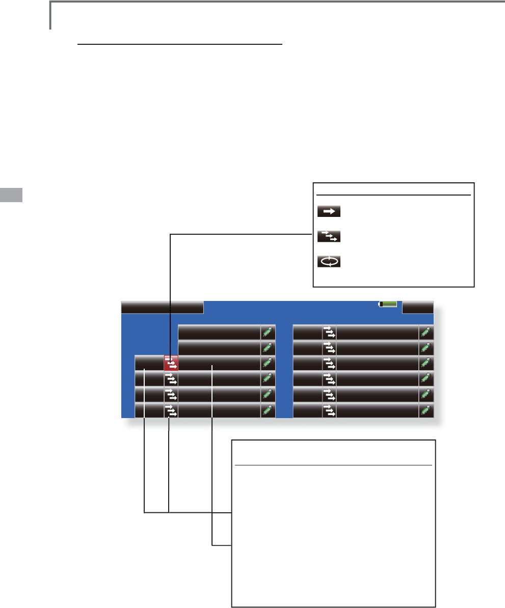
76 <Linkage Menu>
85%
Sound Model1
No Switch Mode
Start up
3RZHURí
2
3
4
5
6
File Rec
1
No Switch Mode
8
9
10
11
12
File Rec
7
1/2
SG
$VVL
J
QPHQWRIDXGLR¿OHVWRVZLWFKHV
$XGLR¿OHVFDQEHVDYHGWR
6
'FDUGEHIRUHKDQG
7RXFKWKHÀOHEXWWRQRIWKH1R
\
RXZDQWWR
V
HW$OLVWRIWKHÀOHVVWRUHGRQWKH
6
'FDUGLV
GL
V
S
OD
\
HG
6HOHFWWKHDXGLRÀOH
\
RXZDQWWR
S
OD
\
EDFN
I
U
R
PWK
H
O
LV
W
RI
DXGLR
À
O
HV
*
S
i
nce t
h
e au
di
o f
il
es are p
l
aye
d
b
ac
k
w
h
en t
h
e au
di
o f
il
e
n
ames in the list are touched
,
the file contents can be
c
hecked before assignment.
7RXFKWKH>)LOH@EXWWRQWRDVVL
J
QWKHÀOHV
6ZLWFKHVDUHDOVRVHOHFWHGIRU1Ra
7
RXFKWKH
>
18//
@
EXWWRQWRFDOOWKH6ZLWFKVHOHFW
VFUHHQ
6
HTXHQWLDOO\SOD\LQJEDFNUHJLVWHUHG¿OHHDFK
ti
me operated b
y
1 sw
i
tch
T
hi
s
i
s use
d
w
h
en ca
lli
ng t
h
e or
d
er of
m
aneuvers, etc.
>6HWW
L
QJPHWKRG
@
$
I
WHUVHOHFW
L
QJWKHVZ
L
WFKSUHVVWKH>ń@
EXWWRQ7KHEXWWRQG
L
VSOD\WKHUHD
I
WHU
L
V
VZ
L
WFKHGDVVKRZQ
L
QWKHVFUHHQDERYH
$VV
L
JQWKHDXG
L
R
À
OHV
L
QWKHRUGHU
L
QZK
L
FK
\RXZDQWWRS
O
D\W
K
HP
E
DF
N
7
K
HDX
GL
R
¿O
HVDUHS
O
D\H
G
E
DF
N
HDF
K
W
L
PHW
K
H
sw
i
tc
h
se
l
ecte
d
by
t
h
e a
b
ove sett
i
n
g
i
s turne
d
on.
6
HOHFWWKHVZLWFKDQGLWV
2
1GLUHFWLRQDWWKH
6
ZLWFKVHOHFWVFUHHQ
)RUDGHWDLOHGGHVFULSWLRQRIWKHVHOHFWLRQPHWKRG
V
HH6ZLWFKVHWWLQJPHWKRGDWWKHEDFNRIWKLV
PDQXDO
M
o
d
e
b
utton
3
OD\LQ
J
EDFNUH
J
LVWHUHGILOH
R
QO
\
RQFH
3
OD\LQ
J
EDFNUH
J
LVWHUHGILOH
U
H
S
HDWHGO
\
6
HTXHQWLDOO\SOD\LQ
J
EDFN
U
H
J
LVWHUHGILOHHDFKWLPH
RS
HUDWHGE
\
VZLWFK
o
í

77
<Linkage Menu>
System mode selection
7KH70=LVIRU*+]RQO\7KHV\VWHPFDQ
be selected from among the 5 systems FASSTest
18CH, FASSTest 12CH, FASST MULT, FASST
7CH, S-FHSS. Select the system matched to the
type of receiver used.
Receiver linking
The receiver can be controlled without being
affected by other transmitters by linking it with the
transmitter used. When using a receiver other than
that of the purchased set, linking is necessary.
Dual receiver function (only FASSTest 18CH
mode)
Two sets of receivers, and a function which can
be linked. Two sets of receivers are recognized
individually. For example, in R7008SB, CH output
setting function is used, by setting one set as "1-
8CH", and setting one more set as "9-16CH", two
sets of receivers can be carried in one set of the
model, and 1-16CH can be used now. If a Dual
receiver function is used, the following function
can set up individually.
䊶Battery fail-safe voltage setup
䊶Telemetry function ON/OFF
䊶Sensor setup
Telemetry function (FASSTest mode only)
To use the telemetry function, set “Telemetry” to
“ON”.
D/L Interval (FASSTest mode only)
When a telemetry function is enabled, the receiving
interval (down-link interval) of sensor data can be
changed.
ŏ5HWXUQWR/LQND
J
H0HQ
X
ŏ7RXFKWKH>6\VWHP7\SH@EXWWRQLQWKH/LQNDJH
0HQXWRFDOOWKHVHWX
S
VFUHHQVKRZQEHORZ
System Type
6
\VWHPPRGHVHWWLQ
J
5HFHLYHUOLQN
If a D/L interval is enlarged, although renewal of a
sensor data display becomes slow, a stick response
will improve.
Battery fail-safe voltage setup (only FASSTest
mode)
The voltage which battery fail-safe commits at the
WLPHRIDOLQNFDQEHVHWXS9$UHFHLYHU
memorizes at the time of a link.
Linkin
g
method
%ULQ
J
WKHUHFHLYHUWREHOLQNHGWRZLWKLQFP
R
IWK
H
WU
D
Q
V
PLWW
H
U
3UHVVWKH
>
/LQN
@
EXWWRQLQWKH
>
/LQN
@
ER[RI
>
6
\
VWHP7
\S
H
@
7KHWUDQVPLWWHUHPLWVDFKLPHVRXQGDQG
H
QW
H
U
V
WK
H
OLQNP
RGH
7KHUHFHLYHU
S
RZHULVLPPHGLDWHO
\
WXUQHGRQ
$ERXWVHFRQGVDIWHUWKH
S
RZHULVWXUQHG
R
QWK
H
U
HFH
LY
H
U
H
QW
H
U
V
WK
H
OLQNZ
D
LW
V
W
D
W
H
5HFHLYHUOLQNZDLWLVDERXWVHFRQG
,IOLQNLQ
J
LVVXFFHVVIXOWKHUHFHLYHU/('
FKDQ
J
HVIURPUHGWR
J
UHHQWKHOLQNPRGH
HQGVDQGWKHUHFHLYHU,'FRGHLVGLV
S
OD
\
HG
,IOLQNLQ
J
IDLOVDQHUURUPHVVD
J
HLVGLVSOD\HG
%ULQ
J
WKHWUDQVPLWWHUFORVHUWRWKHUHFHLYH
U
DQGUH
S
HDWWKH
S
URFHGXUHDERYHIURP6WH
S
*
Do not perform t
h
e
li
n
ki
n
g
operat
i
on w
h
en t
h
e
d
r
i
ve motor
i
s connecte
d
an
d
t
h
e en
gi
ne was starte
d
.
* When
y
ou use two sets of receivers, please be sure to use
i
t, after performin
g
a setup a "primar
y
" and "secondar
y
" in
the "dual" mode.
*Since two sets of receivers cannot be individually
r
ecogn
i
ze
d
w
h
en t
h
e setup a "pr
i
mary" an
d
"secon
d
ary"
i
s
n
ot carried out, it becomes impossible to receive telemetry
d
ata correctly, and makes it.
*
T
h
e
li
n
k
of two sets of rece
i
vers s
h
ou
ld
perform one
li
n
k
operat
i
on at a t
i
me. If two power supp
li
es of a rece
i
ver are
s
w
i
tc
h
e
d
on s
i
mu
l
taneous
ly
,
i
t
i
s correct
ly
unrece
i
va
bl
e
by
t
h
e transm
i
tter s
id
e.
* If a dual receiver function is used, in order to receive
s
ensor information b
y
turns from two sets of receivers,
r
enewal of telemetr
y
data becomes slow rather than a
s
in
g
le receiver's case.
* It
c
ann
o
t link
w
ith thr
ee
se
t
s
o
f r
ece
i
ve
r
s
.
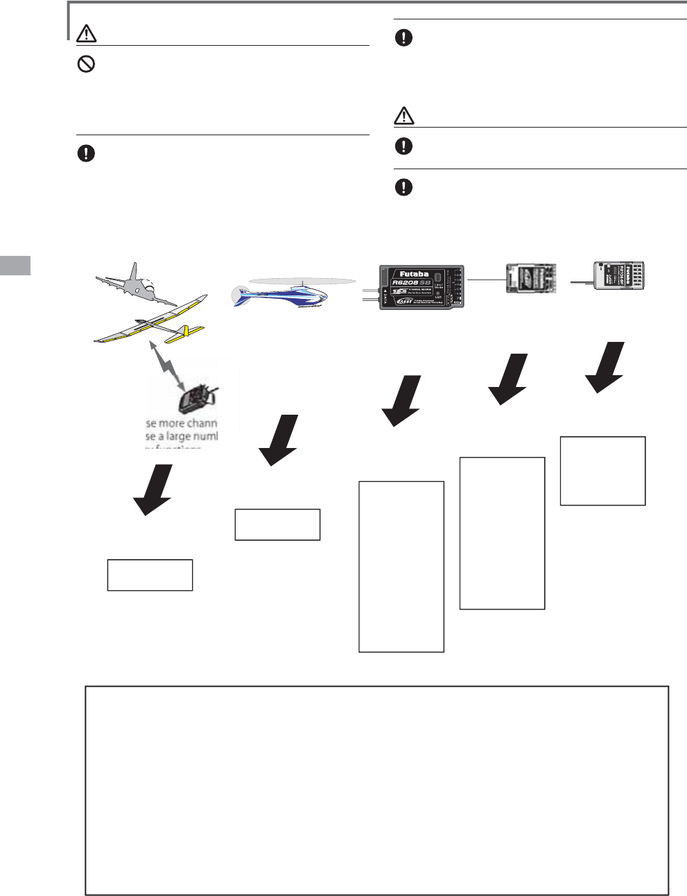
78 <Linkage Menu>
-Response speed has
priority over number
of channels
-Telemetry requires
only the remaining
receiver battery
-Want to use a
previously used
receiver as is
-Want to use a
miniature receiver
for indoor planes
-Want to use an
S-FHSS system
miniature receiver
FASSTest 18CH
FASSTest 12CH
FASST MULT FASST 7CH S-FHSS
R608FS
R6008HS
R6108SB
R6208SB
R6014HS
R6014FS
R6203SB
R6203SBE
R6202SBW
R7008SB
R617FS
R6004FF
R616FFM
R6106HF
R6106HFC
R6203SB
R6203SBE
R6202SBW
R2006GS
R2106GF
R2008SB
R7008SB
(Usable receivers)
-Want to use more channels
-Want to use a large number
of telemetry functions
(
The time of December
,
2011
)
W
ARNING
D
o not perform t
h
e
li
n
ki
ng operat
i
on w
h
en t
h
e
d
r
i
ve motor
i
s connecte
d
an
d
t
h
e eng
i
ne was
s
tarted
.
䂓
I
na
d
vertent rotat
i
on of t
h
e motor or acce
l
erat
i
on of t
h
e eng
i
ne
is extremely dangerous.
If link operation is completed, please check that a
r
eceiver is returned on and it can once be o
p
erated
wi
t
h
t
h
e
li
n
k
e
d
transm
i
tter.
C
h
ec
k
operat
i
on suff
i
c
i
ent
l
y
b
efore f
l
y
i
ng afte
r
li
n
ki
n
g
.
䂓
I
f the same receiver is sendin
g
in the vicinit
y
, there is the dan
g
er
t
h
at t
h
e transm
i
tter may
b
e
li
n
k
e
d
w
i
t
h
t
h
at rece
i
ver
.
C
A
U
TI
ONS
A
l
ways turn on t
h
e transm
i
tter power after
li
n
ki
ng
i
s comp
l
ete.
W
h
en pa
i
r
i
n
g
w
i
t
h
t
h
e transm
i
tter,
b
e sure t
h
at a
prev
i
ous
ly
li
n
k
e
d
transm
i
tter
i
s not transm
i
tt
i
n
g
System Type
䂓FA
SS
T
est
1
8C
H
-
-
-
䂓FA
SS
T
est
12
C
H
---
䂓FA
SS
T M
U
LT
-
-
-
䂓FA
SS
T 7
C
H
-
-- FASST-7CH s
y
stem receiver mo
d
e. Up to 7 c
h
anne
l
s can
b
e use
d.
䂓
S
-FH
SS
--- S-FHSS s
y
stem receiver mode. Up to 8 channels can be used
.
F
ASSTest s
y
stem receiver mode. Applicable with the telemetr
y
sensor unit. Up to
18 c
h
anne
l
s
(l
inear 16+ON/OFF2
)
can
b
e use
d.
F
ASSTest s
y
stem receiver mode. Applicable with receiver voltage displa
y
. Up to 12
c
h
anne
l
s (
l
inear10+ON/OFF2) can
b
e use
d
. Te
l
emetry Sensorcannot
b
e use
d
,
b
ut
the res
p
onse s
p
eed is a faster than that of the 18CH mode.
F
ASST-MULT system receiver mode. Up to 18 channels (linear 16+ON/OFF2) can
b
e used
.
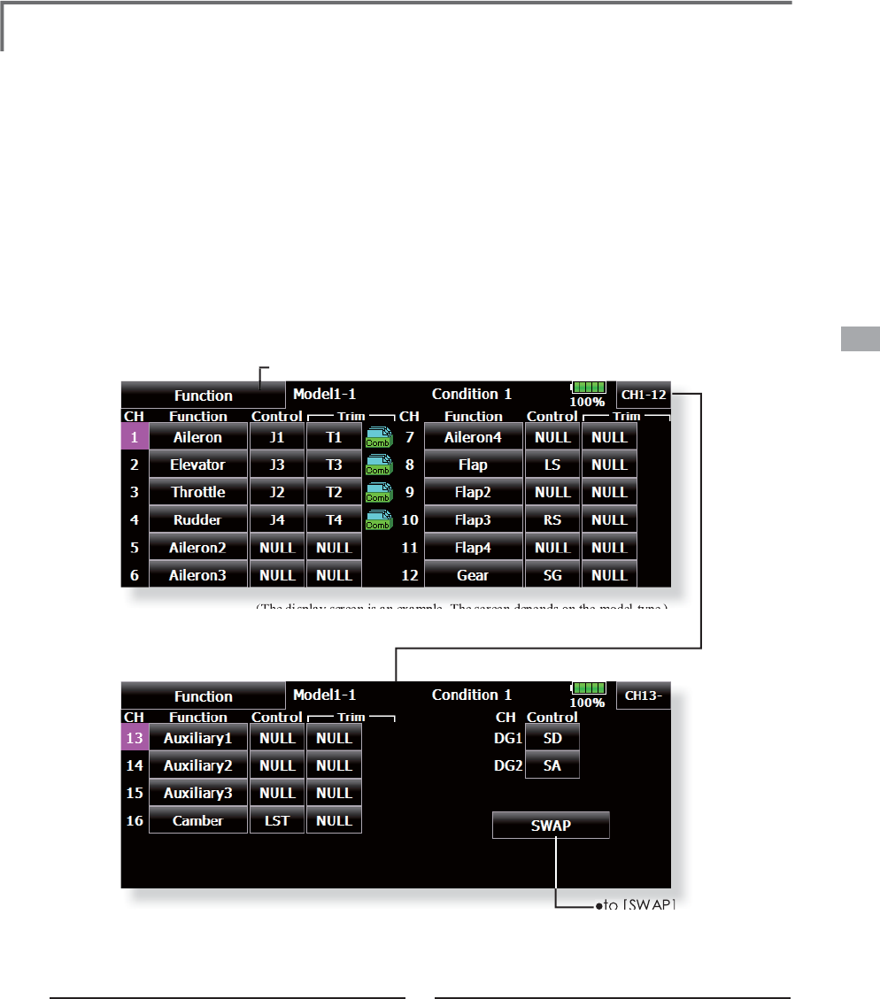
79
<Linkage Menu>
ŏ
5HWXUQWR/
L
QNDJH0HQX
ŏWR
>6:$3@
ŏ
7RXFKWKH>)XQFWLRQ@EXWWRQLQWKH/LQNDJH
0
HQXWRFD
OO
W
K
HVHWXSVFUHHQV
K
RZQ
E
H
O
RZ
Function &KDQQHODVVL
J
QPHQWRIHDFKIXQFWLRQFDQEHFKDQ
J
HG
W
h
en you se
l
ect mo
d
e
l
an
d
w
i
ng
(
swas
h)
types,
y
ou will find that the optimized combinations o
f
servo out
p
ut channels and functions have been
al
rea
d
y preset. If you wou
ld
lik
e, on t
h
e funct
i
on
-
settin
g
screen of the linka
g
e menu,
y
ou can freel
y
c
hange combinations of servo output channels,
funct
i
ons
(
a
il
eron, e
l
evator, etc
)
, an
d
i
npu
t
c
ontrollers (sticks, switches, trim levers and trim
switches). You can also assign the same function to
m
u
l
t
i
p
l
e servo output c
h
anne
l
s suc
h
as ass
i
gn
i
ng
e
levator function to CH2 and CH3.
(The
display
screen
is
an
example
.
The
screen
depends
on
the
model
type
.
)
Function chan
g
e
7
RXF
KWK
H
I
X
Q
F
WL
R
Q
EX
WW
R
Q
R
IWK
H
F
K
D
QQ
H
O
\
RXZDQWWRFKDQ
J
HWRFDOOWKHIXQFWLRQOLVW
6HOHFWWKHIXQFWLRQ\RXZDQWWRFKDQ
J
H
7RXFK><HV@7KHGLVSOD\UHWXUQVWRWKHRUL
J
LQDO
V
FUHHQ
:KHQ\RXZDQWWRFDQFHOIXQFWLRQ
F
KDQ
J
HWRXFK>1R@
*
Mu
l
t
i
p
l
e c
h
anne
l
s can
b
e ass
i
gne
d
to 1 funct
i
on.
D
G1, DG2 (switch channels)
These two channels can be used as switch
channels. You can freely change combinations
b
etween servo output c
h
anne
l
s an
d
i
nput contro
ll
ers
(sticks, switches, trim levers and trim switches).
O
peration control chan
g
e
7
RXF
KWK
H
FR
QWU
R
O
EX
WW
R
Q
R
IWK
H
F
K
D
QQ
H
O
\RXZDQWWRFKDQ
J
H$&RQWUROVHOHFW
VFUHHQ
VWLFNVZLWFKNQREWULPOHYHUHWF
LV
GLV
S
OD
\
HG
6HOHFWWKHFRQWURO
\
RXZDQWWRR
S
HUDWH
7RXFK
>
&ORVH
@
7KHGLV
S
OD
\
UHWXUQVWRWKH
SUHFHGLQ
J
VFUHHQ
*The same control can be assigned to multiple channels.
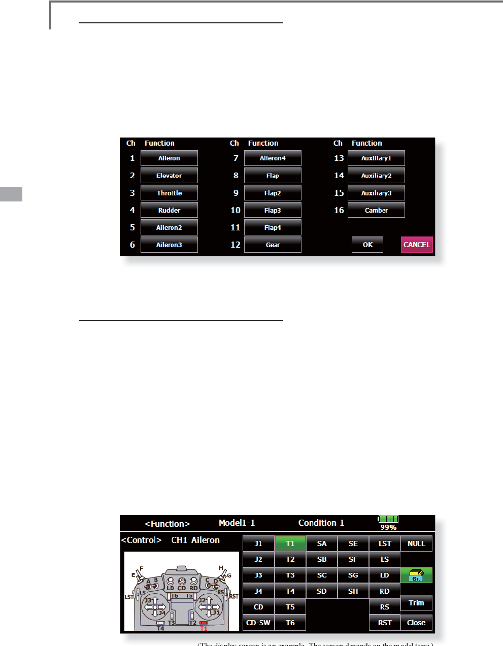
80 <Linkage Menu>
(The
display
screen
is
an
example
.
The
screen
depends
on
the
model
type
.
)
Trim chan
g
e
7RXFKWKH7U
L
PEXWWRQWRFDOOWKH7U
L
PVHWX
S
VFUHHQ
7KH
I
ROORZ
L
Q
J
L
WHPVFDQEHVHWDWWKH7U
L
P
VH
W
X
S
VFUHHQ
ŏ+DUGZDUHVHWW
L
Q
J
6HOHFW
L
RQR
I
VZ
L
WFKHWF
ZK
L
FKFRQWUROVWU
L
P
7KHVHOHFWVFUHHQ
L
V
FDOOHGE\WRXFK
L
Q
J
WKH>+:6HOHFW@EXWWRQ
ŏ5DWHVHWW
L
Q
J
ŏ2SHUDW
L
RQVWHSVHWW
L
Q
J
ŏ7U
L
PPRGHVHWW
L
Q
J
1RUPDOPRGH1RUPDOWULPSDUDOOHOVKLIWWULP
RSHUDWLR
Q
S
WAP
I
f [SWAP]
i
s pus
h
e
d
,
i
t can
b
ecome t
h
e fo
ll
ow
i
n
g
s
creen and can re
p
lace two functions with the
d
ata
se
t a
s
e
a
ch
ch
ann
el.
7
RXF
KWK
H
7ULP
EX
WW
R
QWZ
R
F
K
D
QQ
H
O
V
W
R
FKDQ
J
HLVSXVKHG
,I
>
2.
@
LV
S
XVKHGWZRFKDQQHOVZLOO
LQWHUFKDQ
J
H
,WFDQFKRRVHRQO
\
WRWZR
$7/PRGH$7/R
S
HUDW
L
RQPRGH5HYHUVH
L
VDOVR
S
RVVLEOH
&
750PRGH0D[LPXPFKDQJHQHDUFHQWHUE\
FHQWHUWULPR
S
HUDWLRQ
ŏ6H
S
DUDWHFRPE
L
QDW
L
RQPRGH7U
L
PGDWDDUH
V
HWWR
ÁLJ
KWFRQG
L
W
L
RQV
6HSDUDWHPRGH7U
L
PDG
M
XVWPHQW
I
RUHDFK
ÁLJ
KW
FRQG
L
W
L
R
Q
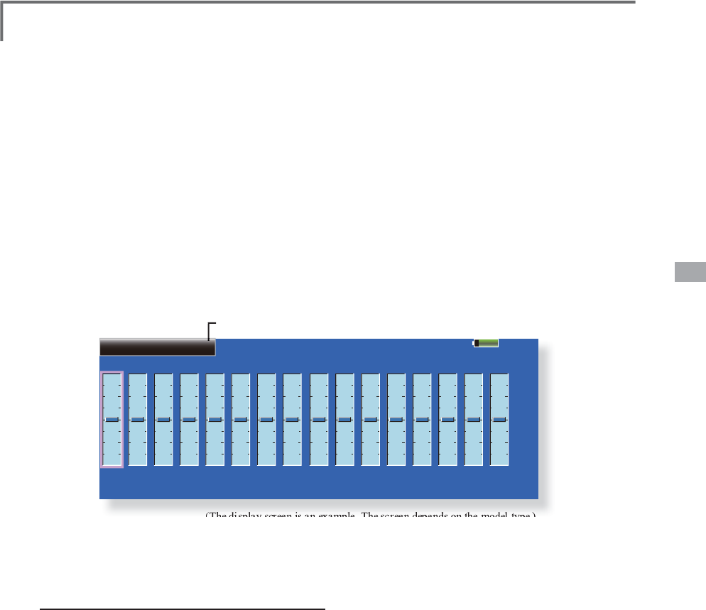
81
<Linkage Menu>
Model1
Sub-Trim
CH2
RUD
+0
CH1
ELE
+0
CH4
AIL
+0
CH3
THR
+0
CH6
ABK
+0
CH5
GEA
+0
CH8
AUX5
+0
CH7
AUX6
+0
CH10
AUX3
+0
CH9
AUX4
+0
CH12
AUX1
+0
CH11
AUX2
+0
CH14
AUX1
+0
CH13
AUX1
+0
CH16
AUX1
+0
CH15
AUX1
+0
85%
ŏ
5HWXUQWR/LQNDJH0HQX
ŏ
7RXFKWKH>6XE7ULP@EXWWRQLQWKH/LQND
J
H0HQX
W
RFDOOWKHVHWX
S
VFUHHQVKRZQEHORZ
Sub-Trim
6
HWWLQ
J
RIQHXWUDOSRVLWLRQRIHDFKVHUYR
(The
display
screen
is
an
example
.
The
screen
depends
on
the
model
type
.
)
The
S
ub-Trim function is used to set the servo
neutra
l
pos
i
t
i
on, an
d
may
b
e use
d
to ma
k
e f
i
ne
adj
ustments to t
h
e contro
l
surface after
li
n
k
a
g
es
a
nd pushrods are hooked up. When
y
ou be
g
in to set
u
p a mo
d
e
l
,
b
e sure t
h
at t
h
e
di
g
i
ta
l
tr
i
ms are set to
th
e
i
r center pos
i
t
i
on.
S
ub tr
i
m ad
j
ustment
7RXFKWKHWU
L
PG
L
VSOD\SDUWR
I
WKHFKDQQHO
\
RXZDQWWRDG
M
XVW
$
G
M
XVWPHQWEXWWRQVDSSHDUVRQWKH6XE7U
L
P
PHQ
X
VFUHHQ
8VHWKHDG
M
XVWPHQWEXWWRQVWRDG
M
XVWWKHVXE
W
U
L
P
ŏ
,Q
L
W
L
DOYDOXH
ŏ
$G
M
XVWPHQWUDQJHa
VWHSV
*
See a
b
ove
5HSHDWWK
L
VVWHS
I
RUHDFKFKDQQHO
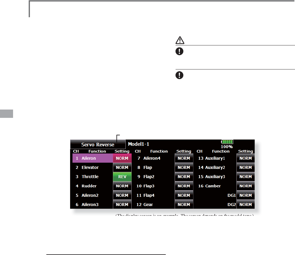
82 <Linkage Menu>
ŏ5HWXUQWR/LQNDJH0HQ
X
ŏ7RXFKWKH>6HUYR5HYHUVH@EXWWRQLQWKH/LQND
J
H
0HQXWRFDOOWKHVHWX
S
VFUHHQVKRZQEHORZ
Servo Reverse
8
VHWRUHYHUVHWKHWKURZGLUHFWLRQ
(The
display
screen
is
an
example
.
The
screen
depends
on
the
model
type
.
)
Servo Reverse chan
g
es the direction of an
i
n
di
v
id
ua
l
servo’s res
p
onse to a contro
l
st
i
c
k
m
ove
m
e
nt
.
For CCPM
h
e
li
copters,
b
e sure to rea
d
t
h
e
s
ect
i
on on Swas
h
AFR
b
efore revers
i
n
g
an
y
servos.
W
ith CCPM helicopters, alwa
y
s complete
y
our
s
ervo revers
i
ng pr
i
or to any ot
h
er programm
i
ng.
If
y
ou use pre-
b
u
il
t A
i
rp
l
ane
/
Sa
il
p
l
ane funct
i
ons
that control multiple servos, it ma
y
be confusin
g
t
o
t
ell
whe
t
he
r t
he
se
r
vo
n
eeds
t
o
be
r
eve
r
sed
o
r a
s
ett
i
n
g
i
n t
h
e funct
i
on nee
d
s to
b
e reverse
d
. See t
h
e
instructions for each s
p
ecialized function for furthe
r
d
eta
il
s. A
l
ways c
h
ec
k
servo
di
rect
i
on pr
i
or to every
S
ervo revers
i
ng procedure
After sett
i
ng up a new mo
d
e
l
,
b
e sure to
d
ef
i
ne a
ll
spec
i
a
l
menus. Be sure t
h
at a
ll
servos
are plu
gg
ed into the proper receiver channels.
N
ow,
d
eterm
i
ne w
h
et
h
er you nee
d
to reverse any
c
h
anne
l
s
by
mov
i
n
g
eac
h
st
i
c
k
an
d
o
b
serv
i
n
g
t
h
e
correspondin
g
movement in the model’s controls.
7RXFKWKHGHVLUHGFKDQQHO·V6HWWLQ
J
EXWWRQ
WRFKRRVHWKH
S
UR
S
HUGLUHFWLRQIRUWKHVHUYR
7
RXF
K´<
HV
µLQWK
H
Q
H
[W
VF
U
HH
Q
5HSHDWIRUHDFKVHUYRQHHGLQ
J
UHYHUVDO
:KHQGRQH
WRXFK´6HUYR5HYHUVHµWRUHWXUQWR
WKH/LQND
J
H0HQX
ÀL
J
KWDVDQDGGLWLRQDOSUHFDXWLRQWRFRQ¿UPSURSHU
mo
d
e
l
memory,
h
oo
k
ups, an
d
ra
di
o funct
i
on.
WARNIN
G
B
HIRUHDÀLJKWLWDOZD\VFHUWDLQO\FKHFNVWKDWD
selection model, servo o
p
eration, the direction
of
s
ervo operation, and a switch setup are ri
g
ht.
I
ni
t
i
a
l
sett
i
n
g
of a motor
ch
anne
l
i
s reverse.
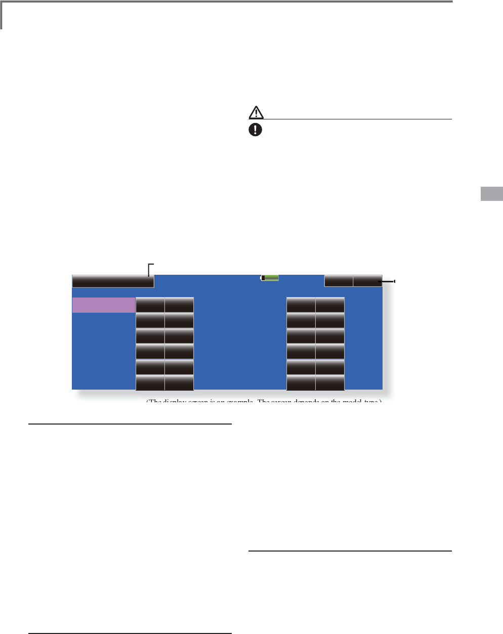
83
<Linkage Menu>
Fail Safe Model1 Batt. F/S
Release
CH Function Function
2
3
4
5
6
1
Gear
Air Brake
Throttle
Aileron
Elevator
Rudder 8
9
10
11
12
7Auxiliary6
Auxiliary5
Auxiliary4
Auxiliary3
Auxiliary2
Auxiliary1
85%
Mode
Hold
OFF
OFF
B.F/S F/S Posi. CH
OFF
OFF
OFF
Hold OFF
Hold OFF
Hold OFF
Hold OFF
Hold OFF
Mode
Hold
OFF
OFF
B.F/S F/S Posi.
OFF
OFF CH13-
OFF
OFF
Hold OFF
Hold OFF
Hold OFF
Hold OFF
Hold OFF
ŏ
5HWXUQWR/
L
QNDJH0HQX
ŏ
7RXFKWKH>)D
L
O6D
I
H@EXWWRQ
L
QWKH/
L
QNDJH
0
HQXWRFD
OO
W
K
HVHWXSVFUHHQV
K
RZQ
E
H
O
RZ
Fail Safe 6HWVWKHVHUYRVRSHUDWLQ
J
SRVLWLRQZKHQWUDQVPLWWHUVL
J
QDOVFDQQRORQ
J
HUEHUHFHLYHGRU
ZKHQWKHUHFHLYHUEDWWHU\YROWD
J
HGURSV
(The
display
screen
is
an
example
.
The
screen
depends
on
the
model
type
.
)
T
h
e Fa
il
safe funct
i
on may
b
e use
d
to set up pos
i
t
i
ons
t
hat the servos move to in the case of radio interference.
W
h
en t
h
e rece
i
ver
b
attery vo
l
tage
d
rops, t
h
e servo
c
an
b
e move
d
to a preset pos
i
t
i
on.
(
Batter
y
fa
il
saf
e
function) A batter
y
fail safe function reset switch can be
set. (Initial setting: Throttle stick maximum slow side)
You ma
y
set either of two positions for eac
h
c
hannel: Hold, where the servo maintains its las
t
c
ommanded
p
osition, or Failsafe, where each servo
m
oves to a pre
d
eterm
i
ne
d
pos
i
t
i
on. You may c
h
oose
ei
t
h
er mo
d
e for eac
h
c
h
anne
l.
T
h
e T18MZ system a
l
so prov
id
es you w
i
t
h
a
n a
d
vance
d
b
attery mon
i
tor
i
ng funct
i
on t
h
a
t
warns
y
ou when the receiver batter
y
has onl
y
a
little power remainin
g
. In this case, each servo is
P
RYHGWRWKHGH¿QHGIDLOVDIHSRVLWLRQ7KHEDWWHU\
ID
LO
VDIHPD\
E
HUH
O
HDVH
G
E
\RSHUDW
L
QJDSUH
G
H
¿
QH
G
c
ontro
l
on t
h
e transm
i
tter
(d
efau
l
t
i
s t
h
rott
l
e
)
,
Fail safe setting procedure
D
ecide which channels
y
ou want to
g
o to preset
pos
i
t
i
ons, an
d
w
hi
c
h
ones you want to ma
i
nta
i
n
th
e
i
r
l
ast comman
d
e
d
pos
i
t
i
on. To se
l
ect t
h
e fa
il
safe
m
ode
y
ou wish to set, use the F/S button. This
b
utton togg
l
es
b
etween t
h
e two mo
d
es.
(
Ho
ld
, F
/
S
)
F
/S mode settin
g:
7RXFKWKH)6EXWWRQRIWKHFKDQQHO
\
RX
Z
DQWWRVHWDQGVHWWKDWFKDQQHOWRWKH
>
)6
@
PRGH
+ROGWKHFRUUHVSRQGLQ
J
VWLFNFRQWUROVOLGHU
R
URWKHUFRQWUROLQWKH
S
RVLWLRQ
\
RXZDQW
W
K
H
VH
UY
R
W
R
P
R
Y
H
W
R
ZK
H
QWK
H
I
D
LO
VD
I
H
I
XQFWLRQLVDFWLYDWHGDQGWRXFKWKH)
6
S
RVLWLRQEXWWRQ7KDW
S
RVLWLRQLVGLV
S
OD
\
HGLQ
S
HUFHQWD
J
H
*
When you want to return that channel to the Hold mode,
touch the [F/S] button again.
Battery fail safe setting procedure
To select the B.F/S mode, touch the [B.F/S]
b
utton. Eac
h
t
i
me t
h
e
b
utton
i
s touc
h
e
d
,
i
t togg
l
es
d
o not continue to fly, land as soon as possible.
Remem
b
er,
i
f t
h
e pre
d
ef
i
ne
d
contro
l
su
dd
en
l
y
moves to a pos
i
t
i
on
y
ou
did
not comman
d
,
l
an
d
at
once and check
y
our receiver batter
y
.
'
H
¿
QHVVHUYRSRV
L
W
L
RQZ
K
HQV
LJ
QD
O
VDUH
O
RVWDQ
G
when receiver batter
y
volta
g
e becomes low.
W
AR
N
I
NG
For safet
y
, alwa
y
s set the fail safe functions.
Ɣ
(VSHF
L
D
OO\
VHWW
K
HW
K
URWW
O
HF
K
DQQH
O
ID
LO
VDIHIXQFW
L
RQVRW
K
D
W
t
h
e servo moves to t
h
e max
i
mum s
l
ow s
id
e for a
i
rp
l
anes an
d
to the slow side from the hovering position for helicopters.
Crashin
g
of the model at full hi
g
h when normal radio waves
cannot
b
e rece
i
ve
d
d
ue to
i
nterference, etc.,
i
s ver
y
d
an
g
erous
.
Ɣ
,IIDLOVDIHLVUHVHWE
\
WKURWWOHVWLFNLWPD
\
EHPLVWDNHQIRUD
Q
en
gi
ne ma
l
funct
i
on an
d
w
ill
b
e reset at t
h
rott
l
e s
l
ow an
d
t
h
e mo
d
e
l
ZLOO
FRQW
L
QXHWR
À
\,I\RX
K
DYHDQ\
G
RX
E
WV
L
PPH
GL
DWH
O
\
O
DQ
G
between [OFF] and [B.F/S].
B.F/S settin
g:
7RXFKWKH
>
%)6
@
EXWWRQRIWKHGHVLUHG
FKDQQHOWRVHWLWWRWKH%)
6PRGH
+ROGWKHFRUUHVSRQGLQ
J
VWLFN95VOLGHURURWKHU
FRQWUROLQWKH
S
RVLWLRQ
\
RXZDQWWKHVHUYRWR
PRYHWRZKHQWKHEDWWHU
\
IDLOVDIHIXQFWLRQLV
DFWLYDWHGDQGWRXFKWKH)6
S
RVLWLRQEXWWRQ
7KLVSRVLWLRQLVGLVSOD\HGLQSHUFHQWD
J
H
*When you want to return that channel to OFF, touch the [B.F/
S] button again
.
B
attery Failsafe Release Function
This function releases the
p
redefined control
f
rom
i
t's
h
e
ld
pos
i
t
i
on after
i
n
di
cat
i
ng t
h
at your
receiver batter
y
is low.
(QWHUWKHFRQWUROVHWW
L
QJVFUHHQE\WRXFK
L
QJ
W
K
H%DWWHU\)
6
5H
O
HDVH
E
XWWRQ1RZ\RXPD
\
FKRRVHWKDWPRY
L
QJWKHWKURWWOHUHVHWVWKH
FRQG
L
W
L
RQRUVHOHFWDQRWKHUVW
L
FNRUVZ
L
WFK
GHDFW
L
YDWHV
L
W7RVHWDGHV
L
UHGWKURWWOHUHOHDVH
SRV
L
W
L
RQPRYHWKHWKURWWOHVW
L
FNWRWKHSR
L
QWDW
ZK
L
FK\RXZ
L
VKWKH%)6WREHUHOHDVHG
ŏ
7R6Z
L
WFK
!
VFUHHQ
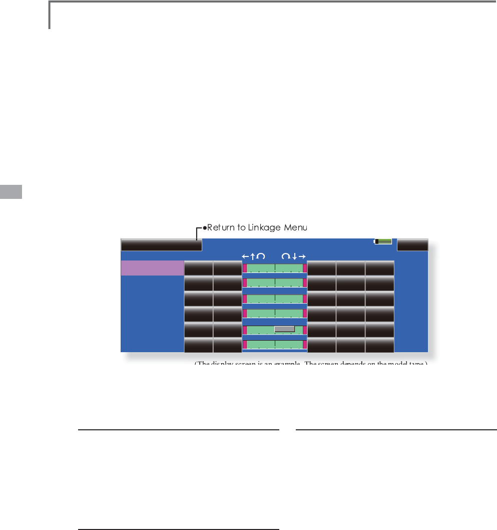
84 <Linkage Menu>
End Point(ATV) Model1
CH Function
2
3
4
5
6
1
Gear
Air Brake
Throttle
Aileron
Elevator
Rudder
85%
Limit
135%
OFF
OFF
135%
135%
135%
135%
135%
Limit
135%
OFF
OFF
135%
135%
135%
135%
135%
Speed
0
OFF
OFF
0
0
0
0
0
Tra vel
100%
OFF
OFF
100%
100%
100%
100%
100%
Tra vel
100%
OFF
OFF
100%
100%
100%
100%
100%
CH7-12
ŏ7RXFKWKH>(QG3RLQW
$79
@EXWWRQLQWKH/LQND
J
H
0HQXWRFDOOWKHVHWX
S
VFUHHQVKRZQEHORZ
End Point (ATV)
6
HWVWKHWUDYHOO
L
P
L
WSR
L
QWDQGVSHHGR
I
HDFKVHUYR
(The
display
screen
is
an
example
.
The
screen
depends
on
the
model
type
.
)
T
he End Point function ad
j
usts the left and ri
g
ht
s
ervo t
h
rows, generates
di
fferent
i
a
l
t
h
rows, an
d
will
correct
i
mproper
li
n
k
a
g
e sett
i
n
g
s.
7K
H7UDYH
O
UDWHFDQ
E
HYDU
L
H
G
IURPWR
i
n eac
h
di
rect
i
on on c
h
anne
l
s 1 to 16. A
l
so
,
t
h
e
Limit point where servo throw stops ma
y
be varied
f
rom 0% to 155%.
S
ervo travel ad
j
ustment
7RXFKWKH7UDYHOEXWWRQR
I
WKHFKDQQHO\RX
ZDQWWRVHW$G
M
XVWPHQWEXWWRQVDSSHDURQ
W
K
HVFUHHQ
8VHWKHVHEXWWRQVWRDG
M
XVWWKHUDWH
ŏ,QLWLDOYDOXH
ŏ$GMXVWPHQWUDQJH
a
5HSHDWWKHSURFHGXUHDERYH
I
RUHDFKUDWH
L
i
m
i
t po
i
nt ad
j
ustment
7RXFKWKH/
L
P
L
WEXWWRQR
I
WKHFKDQQHO\RX
ZDQ
W
W
RVH
W
8VHWKHDG
M
XVWPHQWEXWWRQVWRDG
M
XVWWKHO
L
P
L
W
SR
L
QW
ŏ,QLWLDOYDOXH
ŏ$GMXVWPHQWUDQJH
a
5HSHDWWK
L
VSURFHGXUH
I
RUHDFKO
L
P
L
WSR
L
QW
NOTE: T
h
e
i
n
di
cators on t
h
e screen
di
sp
l
ay actua
l
servo
t
hrow of the each channel. The center
p
osition of the
indicator is based on the Sub-Trim settings. Therefore the
Sub-Trim ad
j
ustment chan
g
es the Limit point displa
y
of the
indicator. The Servo Speed settin
g
is used to set the servo
d
e
l
a
y
for eac
h
c
h
anne
l
, from c
h
anne
l
l
to c
h
anne
l
16. T
h
e
s
y
stem uses t
h
e pro
g
ramme
d
spee
d
(d
e
l
a
y)
to s
l
ow
d
own
servo pos
i
t
i
on c
h
an
g
es. T
h
e Servo Spee
d
sett
i
n
g
can
b
e
v
ar
i
e
d
from 0 to 2
7
i
n eac
h
c
h
anne
l
.
S
ervo speed sett
i
ng
7RXFKWKH6SHHGEXWWRQR
I
WKHFKDQQHO\RX
ZDQ
W
W
RVH
W
8VHWKHDG
M
XVWPHQWEXWWRQVWRDG
M
XVWWKH
V
HUYRVSHH
G
ŏ,Q
L
W
L
DOYDOXH
ŏ$G
M
XVWPHQWUDQJHa
VWHSV
5HSHDWWK
L
VSURFHGXUH
I
RUHDFKFKDQQHO
7RFORVHWK
L
VVFUHHQWRXFKWKH>(QG3R
L
QW
$79
@EXWWRQ
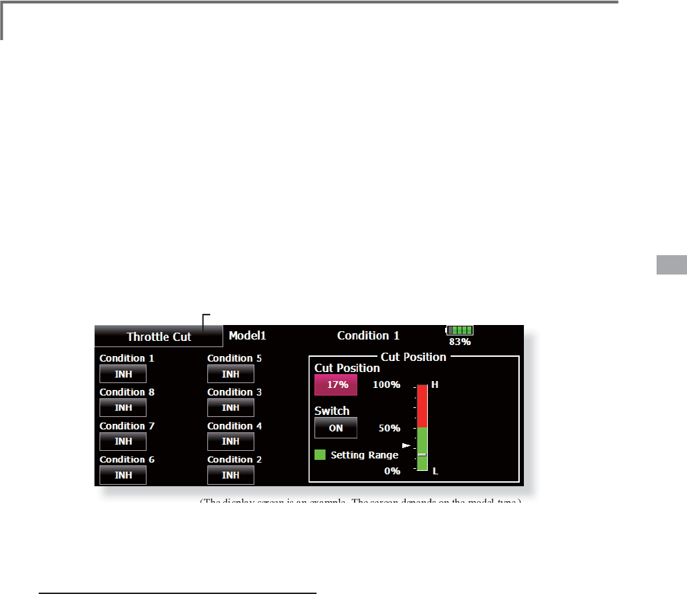
85
<Linkage Menu>
ŏ
5HWXUQWR/LQNDJH0HQX
ŏ
7RXFKWKH>7KURWWOH&XW@EXWWRQLQWKH/LQND
J
H0HQX
W
RFDOOWKHVHWX
S
VFUHHQVKRZQEHORZ
Throttle Cut 6WRSVWKHHQ
J
LQHVDIHO\DQGHDVLO\
DLUSODQHDQGKHOLFRSWHURQO\
(The
display
screen
is
an
example
.
The
screen
depends
on
the
model
type
.
)
Throttle cut provides an eas
y
wa
y
to stop the
H
QJ
L
QH
E
\
ÀL
SS
L
QJDVZ
L
WF
K
Z
L
W
K
W
K
HW
K
URWW
O
HVW
L
F
N
a
t
idl
e. T
h
e act
i
on
i
s not funct
i
ona
l
at
high
t
h
rott
l
e
t
o avoid accidental dead sticks. The switch’s
l
ocat
i
on an
d
di
rect
i
on must
b
e c
h
osen
,
as
i
t
d
efau
l
ts
t
o NULL.
T
hrottle cut sett
i
ng procedure
&RQG
L
W
L
RQWRVHWXSWRXFKWKH,1+EXWWRQWR
D
FW
L
YDWHWKH7KURWWOH&XW
I
XQFW
L
RQ
7KURWWOHFXW
I
XQFW
L
RQVZ
L
WFKVHWW
L
QJ
7
RXFKWKH18//EXWWRQWRFDOOWKH6Z
L
WFK!
V
FUHHQDQGWKHQVHOHFWWKHVZ
L
WFKDQG
L
WV21
GL
UHFW
L
RQ
)RUDGHWD
L
OHGGHVFU
L
SW
L
RQR
I
WKHVHOHFW
L
RQ
P
HWKRGVHH>6Z
L
WFK6HWW
L
QJ0HWKRG@DWWKH
E
DFNR
I
WK
L
VPDQXDO
7KURWWOHFXWSRV
L
W
L
RQVHWW
L
QJ
6
HWWKHWKURWWOHVW
L
FNWRPD[
L
PXPVORZDQG
W
RXFKWKH&XW3RV
L
W
L
RQEXWWRQ$G
M
XVWPHQW
E
XWWRQVDSSHDU$WWKHVDPHW
L
PHWKH
Q
XPHU
L
FDOYDOXHR
I
WKHFXUUHQWPD[
L
PXP
V
ORZV
L
GH
L
VG
L
VSOD\HGDW&XW3RV
L
W
L
RQ
8
VHWKHDG
M
XVWPHQWEXWWRQVWRDG
M
XVWWKH
V
HUYRWUDYHOZKHQWKHWKURWWOHFXW
I
XQFW
L
RQ
L
V
D
FW
L
YDWHG
ŏ
,QLWLDOYDOXH
ŏ
$GMXVWPHQWUDQJH
a
*
W
i
t
h
t
h
rott
l
e st
i
c
k
at
idl
e, a
dj
ust t
h
e rate unt
il
t
h
e eng
i
ne
consistently shuts off, but throttle linkage is not binding.
:
KHQ¿QLVKHG
WRXFKWKH³7KURWWOH&XW´EXWWRQWRH[LW
7
RH[LWWKHVHWWLQ
J
WRXFKWKH>7KURWWOH&XW@
EX
WW
R
Q
N
OTE: W
h
en con
di
t
i
on
i
s set up, a setup of ON
/
OFF can
b
e
p
erformed for every condition. Only as for the condition to
w
hich the throttle cut is an operating state (ON/OFF) from
INH, a throttle cut can turn ON. While the throttle cut has
b
een ON, when a throttle cut chan
g
es to the condition o
f
INH, a cut
i
s cance
l
e
d
by
t
h
e t
h
rott
l
e cut sw
i
tc
h
OFF w
i
t
h
ON, an
d
t
h
e t
h
rott
l
e cut cannot turn ON
i
n t
h
e con
di
t
i
on.
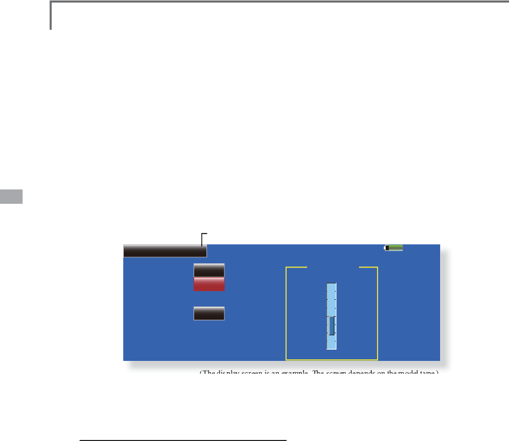
86 <Linkage Menu>
85%
Model 1
Throttle CH
OFF
Switch
ACT/INH
2íVHW H
L
INH
+0%
Idle Down
ŏ5HWXUQWR/LQNDJH0HQ
X
ŏ7RXFKWKH>,GOH'RZQ@EXWWRQLQWKH/LQND
J
H0HQX
WRFDOOWKHVHWX
S
VFUHHQVKRZQEHORZ
Idle Down /RZHUVWKHHQ
J
LQHLGOLQ
J
VSHHG
DLUSODQHDQGKHOLFRSWHURQO\
(The
display
screen
is
an
example
.
The
screen
depends
on
the
model
type
.
)
T
he Idle Down function lowers the en
g
ines idle
E
\
ÀL
SS
L
QJDVZ
L
WF
K
Z
L
W
K
W
K
HW
K
URWW
O
HVW
L
F
N
DW
LGO
H
Th
e act
i
on
i
s not funct
i
ona
l
at
high
t
h
rott
l
e to avo
id
accidental dead sticks. The switch’s location an
d
di
rect
i
on must
b
e c
h
osen
,
as
i
t
d
efau
l
ts to NULL.
Idle down sett
i
ng procedure
7RXFKWKH,1+EXWWRQWRDFW
L
YDWHWKH,GOH
'RZQ
I
XQFW
L
RQ
,GOH'RZQ
I
XQFW
L
RQVZ
L
WFKVHWW
L
QJ
7RXFKWKH18//EXWWRQWRFDOOWKH6Z
L
WFK!
VFUHHQDQGWKHQVHOHFWWKHVZ
L
WFKDQG
L
WV21
G
L
UHFW
L
RQ
)RUDGHWD
L
OHGGHVFU
L
SW
L
RQR
I
WKHVHOHFW
L
RQ
PHWKRGVHH>6Z
L
WFK6HWW
L
QJ0HWKRG@DWWKH
EDFNR
I
WK
L
VPDQXDO
2
II
VHWUDWHVHWW
L
QJ
7RXFKWKH2
II
VHW5DWHEXWWRQ$G
M
XVWPHQW
E
XWWRQVDSSHDURQW
K
HVFUHHQ
8VHWKHVHEXWWRQVWRDG
M
XVWWKHR
II
VHWUDWH
ŏ,QLWLDOYDOXH
ŏ$GMXVWPHQWUDQJH
a
EHFRPHVDQ
L
GOHXS
7RH[
L
WWKHVHWW
L
QJWRXFKWKH>,GOH'RZQ@
E
XWWRQ
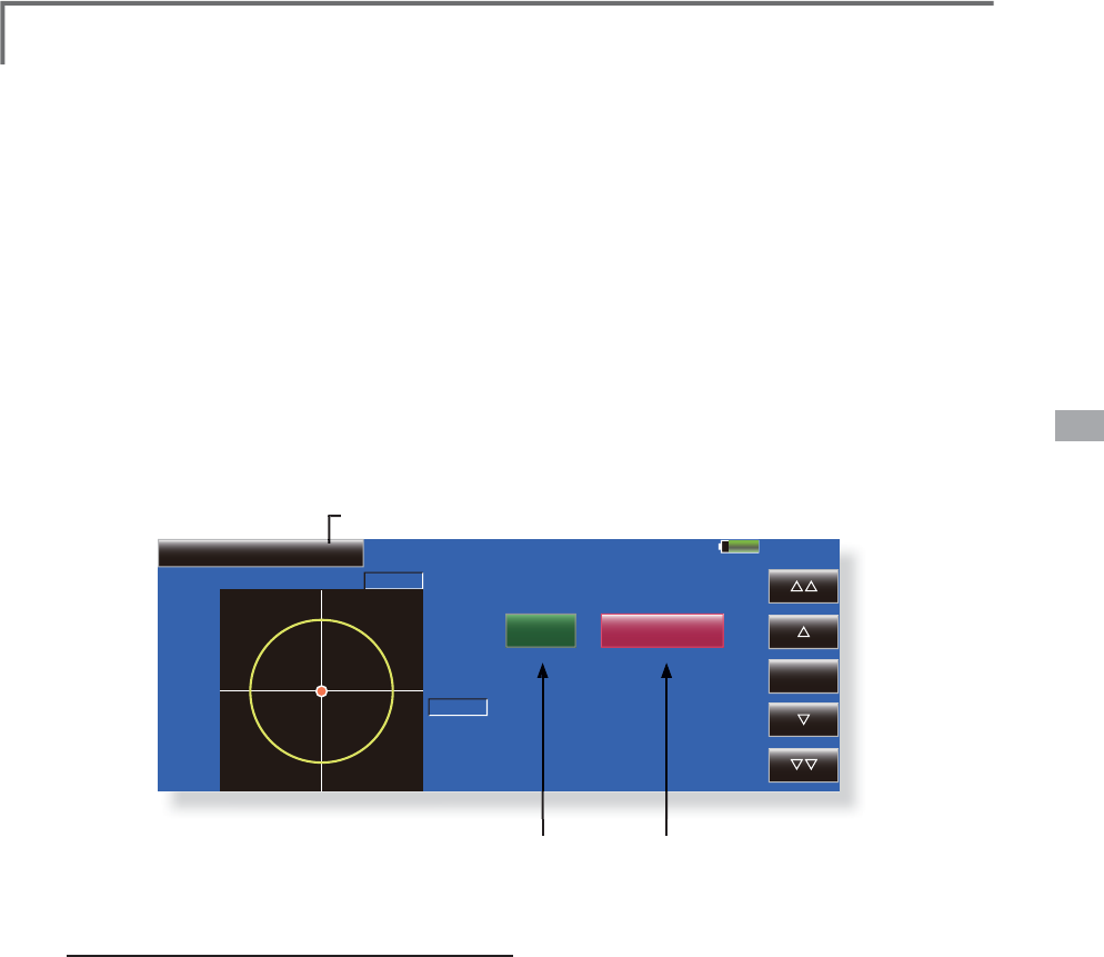
87
<Linkage Menu>
85%
Model 1
Elevator +0%
Swash Ring
ON
Aileron
Rate
+0%
100%
Reset
ŏ
5HWXUQWR/
L
QNDJH0HQX
ŏ7RXFKWKH>6ZDVKULQ
J
@EXWWRQLQWKH/LQND
J
H0HQX
WRFDOOWKHVHWX
S
VFUHHQVKRZQEHORZ
Swash Ring /LPLWVWKHGHFOLQHRIWKHVZDVKSODWHWRSUHYHQWOLQND
J
HGDPD
J
H
+HOLFRSWHURQO\
This function limits the decline of the swash
p
l
ate to prevent
li
n
k
age
d
amage as t
h
e a
il
eron an
d
el
evator operat
i
on
i
s a
dd
e
d
. It
i
s usefu
l
for 3D
h
e
li
s
ettin
g
.
Swash rin
g
settin
g
procedure
3XVKWKH6ZDVKULQ
J
EXWWRQRQWKHOLQND
J
H
PH
Q
X
3XVK$&7
,1+EXWWRQWRDFWLYDWH
*
T
h
e movement area mon
i
tor s
h
ows t
h
e current a
il
eron an
d
e
l
evator va
l
ues an
d
li
m
i
t ran
g
es
by
t
h
e
y
e
ll
ow c
i
rc
l
e.
$G
M
XVWWKHUDWHWRWKHPD[
L
PXPDPRXQWR
I
V
ZDVKSODWHGHFO
L
QH
*
T
he
sw
a
sh
m
ove
m
e
nt
is
li
m
i
t
ed
wi
t
hi
n t
he
ci
r
cle.
$
G
M
XVWPHQWUDQ
J
H
5
D
W
H
EX
WW
RQ
$F
WLY
D
W
H
EX
WW
R
Q
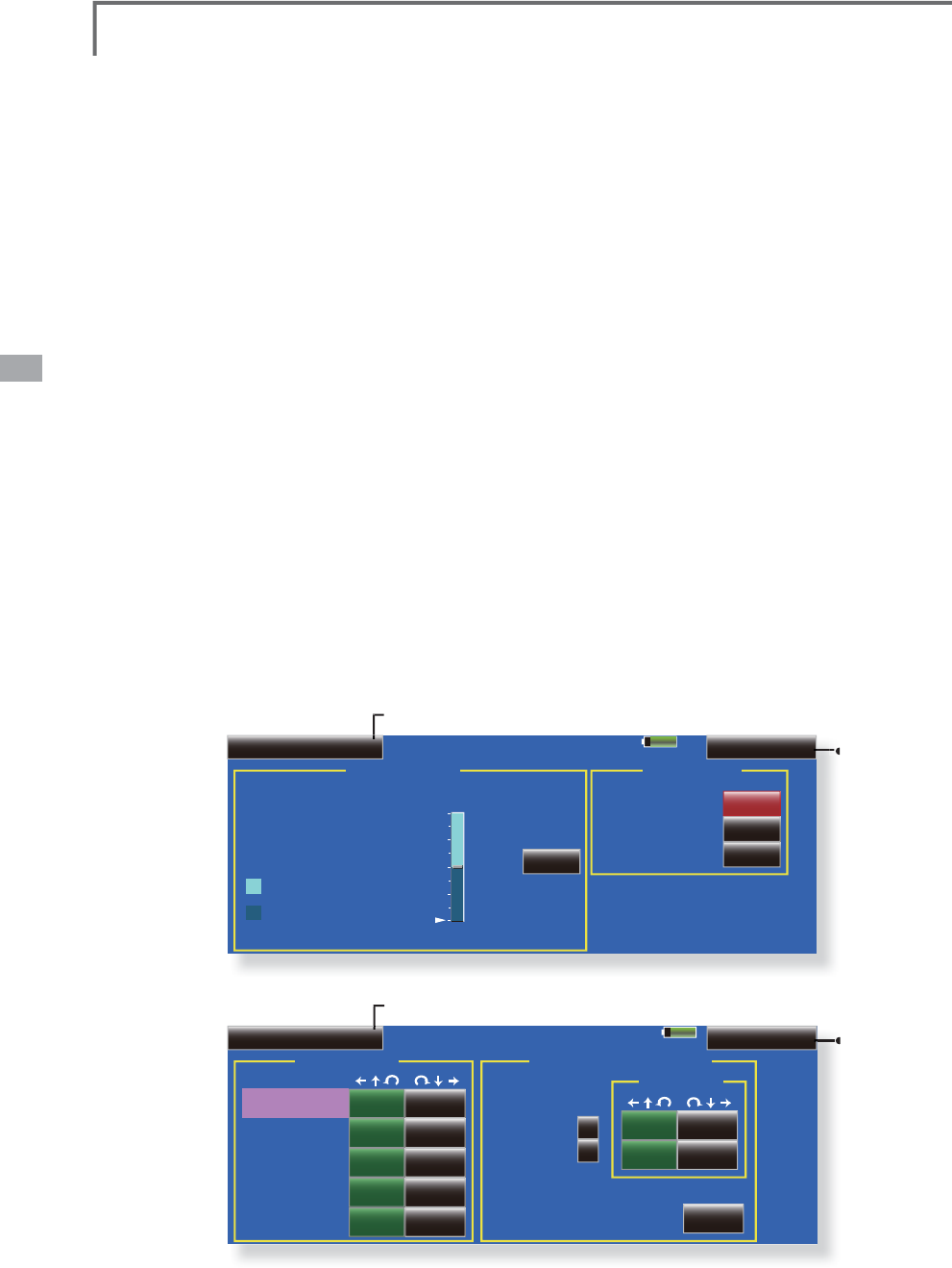
88 <Linkage Menu>
85%
Model 1
Mixing Rate
Swash Detail Swash(AFR)
PIT to ELE
AIL to PIT
ELE to AIL
ELE to PIT
100% 100%
100% 100%
100% 100%
50% 50%
50% 50%
PIT to AIL
Mixing
Linkage Compensation
Function Dir.
Aileron
Elevator
Speed Compensation
0% 0%
0% 0%
0%
Low Pitch
+
+
ŏ5HWXUQWR/LQND
J
H0HQ
X
ŏ
7R
6
ZDV
K
$)5
VFUHHQ
85%
Model 1
Neutral Point Swash AFR
Aileron
Elevator
H100%
50% 50%
0% L
Low Pitch
+50%
Enter Pitch
Swash Swash Detail
High Pitch
+50%
+50%
ŏ
5HWXUQWR/
L
QNDJH0HQX
ŏ
7RXFKWKH>6ZDVK@EXWWRQLQWKH/LQND
J
H0HQXWR
F
DOOWKHVHWX
S
VFUHHQVKRZQEHORZ
Swash
6
ZDVKRSHUDWLRQOLQND
J
HFRUUHFWLRQIXQFWLR
Q
7KLVVZDVKVHWXSVFUHHQGRHVQRWDSSHDUIRUVZDVKW\SH+
N
eutral Point
A
t
y
our linka
g
es, if the servo horn deviates from
t
he perpendicular position at neutral, the linkage
compensat
i
on funct
i
ons may not compensate
e
ffectivel
y
. This neutral point settin
g
reads the
linkage compensation neutral position. However,
thi
s a
dj
ustment on
l
y c
h
anges t
h
e
d
atum po
i
nt of t
h
e
com
p
ensation function on the swash details screen
and does not affect the neutral
p
osition of othe
r
fu
n
c
t
io
n
s.
*
Before usin
g
the compensation function, set the neutral
p
o
i
nt.
S
wash AFR
T
h
e swas
h
AFR funct
i
on a
dj
usts
(i
ncreases
/
decreases/reverse
)
the rate
(
travel
)
of the aileron,
e
levator, and
p
itch functions.
M
i
x
i
n
g
Rate
(
Norma
lly
, t
h
e
i
n
i
t
i
a
l
va
l
ue
i
s use
d
.
)
T
hi
s m
i
x
i
ng rate
i
s use
d
for correct
i
on so t
h
at
t
he swash plate moves in the correct direction fo
r
a
ileron, elevator, and
p
itch o
p
eration.
Compensation mixin
g
is shown below.
*
PIT->AIL
/
PIT->ELE
/
AIL->PIT
/
ELE->AIL
/
ELE->PIT
*
Use t
h
e correspon
di
n
g
compensat
i
on m
i
x
i
n
g
an
d
compensate so t
h
at t
h
e swas
h
p
l
ate moves
i
n t
h
e correc
t
di
r
ec
t
io
n
.
L
inkage Compensation
This compensation mixing is used to correct for
m
u
t
u
a
l
i
nt
e
rf
e
r
e
n
ce
whe
n t
he
a
ile
r
o
n
s
o
r
elev
at
o
r
s
were operated when the throttle stick was in the
s
low or high position.
S
peed
C
ompensat
i
on
T
hi
s spee
d
compensat
i
on funct
i
on compensates
th
e mutua
l
i
nterference w
h
en t
h
e trave
l
of eac
h
s
ervo is different at swash
p
late o
p
eration. Fo
r
HR-3,
i
t compensates t
h
e spee
d
b
y
d
ropp
i
ng t
h
e
operat
i
n
g
spee
d
of t
h
e a
il
eron an
d
p
i
tc
h
servos at
e
levator o
p
eration.
ŏ
7R
6
ZDV
K
'HWDLOVVFUHHQ

89
<Linkage Menu>
Neutral point setting procedure
*Becomes the compensation datum point.
*Adjusting the servo horn so that the neutral point position is
near the 50% position makes the mixing amount small.
+ROGWKHVHUYRKRUQDWDULJKWDQJOHWRWKH
OLQNDJHURGDQGWKHQWRXFKWKH>(QWHU@
EXWWRQDQGUHDGWKHDFWXDOQHXWUDOSRLQW
*The neutral point is displayed on the screen.
$IWHUUHDGLQJWKLVQHXWUDOSRLQWXVHRWKHU
FRPSHQVDWLRQIXQFWLRQVWRPDNHIXUWKHU
DGMXVWPHQWV
7RH[LWWKHVHWWLQJWRXFKWKH>6ZDVK@EXWWRQ
Swash AFR setting procedure
$GMXVWVRWKDWWKHVSHFLILHGRSHUDWLRQ
DPRXQWLVREWDLQHGE\DLOHURQHOHYDWRUDQG
SLWFKRSHUDWLRQ
7RXFKWKHEXWWRQRIWKH$)5UDWHWREH
DGMXVWHG$GMXVWPHQWEXWWRQVDSSHDURQWKH
VFUHHQ
8VHWKHDGMXVWPHQWEXWWRQVWRDGMXVWWKH$)5
UDWH
,QLWLDOYDOXH
$GMXVWPHQWUDQJHa
7RH[LWVHWWLQJWRXFKWKH>6ZDVK@EXWWRQ
Mixing rate setting procedure
+5LVGHVFULEHGDVDQH[DPSOH7KHPL[LQJ
DSSOLHGLQRWKHUVZDVKPRGHVLVGLIIHUHQWEXW
WKHVHWWLQJSURFHGXUHLVWKHVDPH
6HWWKHWKURWWOHVWLFNWRWKHVHWQHXWUDOSRLQW
$GMXVWWKHOHQJWKRIWKHOLQNDJHURGVRWKDW
WKHVZDVKSODWHLVKRUL]RQWDODWWKLVSRVLWLRQ
$OLWWOHDGMXVWPHQWXVLQJVXEWULPVKRXOGEH
2.
$GMXVWVRWKDWSLWFKRSHUDWLRQZKHQWKH
SLWFKFXUYHLVVWUDLJKWLVPD[LPXP
$GMXVWWKH$,/!3,7DPRXQWVRWKHUHLVQR
LQWHUIHUHQFHLQWKHHOHYDWRURUSLWFKGLUHFWLRQ
ZKHQWKHDLOHURQVWLFNLVPRYHGWRWKHOHIW
DQGULJKW
$GMXVWWKHOHIWDQGULJKWVLGHVVHSDUDWHO\
$GMXVWWKH(/(!$,/DQG(/(!3,7DPRXQWV
VRWKHUHLVQRWLQWHUIHUHQFHLQWKHDLOHURQRU
SLWFKGLUHFWLRQZKHQWKHHOHYDWRUVWLFNLV
PRYHGXSDQGGRZQ
$GMXVWWKHXSDQGGRZQVLGHVVHSDUDWHO\
$GMXVWWKH3,7!$,/DQG3,7!(/(DPRXQWV
VRWKDWWKHVZDVKSODWHLVKRUL]RQWDOZKHQWKH
WKURWWOHVWLFNLVVHWWRPD[LPXPVORZDQGIXOO
KLJK
$GMXVWWKHVORZDQGKLJKVLGHVVHSDUDWHO\
7RH[LWVHWWLQJWRXFKWKH>6ZDVK'HWDLOV@
EXWWRQ
Linkage correction setting procedure
6HWWKHOLQNDJHFRPSHQVDWLRQDIWHUVHWWLQJ
WKHPL[LQJUDWH
7KLVIXQFWLRQFRPSHQVDWHVIRUHOHYDWRU
LQWHUIHUHQFHE\DLOHURQRSHUDWLRQRUDLOHURQ
LQWHUIHUHQFHE\HOHYDWRURSHUDWLRQDW/RZ
SLWFKDQG+LSLWFKDWFROOHFWLYHSLWFK+5
HWFFRQWURO
6HWWKHWKURWWOHVWLFNWRWKHPD[LPXPVORZ
SRVLWLRQ0RYHWKHDLOHURQVWLFNWRWKHOHIWDQG
ULJKWDQGDGMXVWWKHDLOHURQFRPSHQVDWLRQ
DPRXQWVRWKDWLQWHUIHUHQFHLQWKHHOHYDWRU
RUSLWFKGLUHFWLRQDWWKDWWLPHLVPLQLPDO
7KHOHIWDQGULJKWVLGHVFDQEHDGMXVWHG
VHSDUDWHO\
,IWKHLQWHUIHUHQFHLQFUHDVHVZKHQWKH
FRPSHQVDWLRQDPRXQWLVLQFUHDVHGPDNH
WKHFRPSHQVDWLRQGLUHFWLRQ
$GMXVWWKHHOHYDWRUFRPSHQVDWLRQDPRXQW
VRWKDWWKHLQWHUIHUHQFHLQWKHDLOHURQRUSLWFK
GLUHFWLRQZKHQWKHHOHYDWRUVWLFNZDVPRYHG
XSDQGGRZQLVPLQLPDO
3HUIRUPDLOHURQDQGHOHYDWRU
FRPSHQVDWLRQVLPLODUO\IRUWKHWKURWWOHVWLFN
IXOOKLJKVLGH
7RH[LWVHWWLQJWRXFKWKH>6ZDVK'HWDLOV@
EXWWRQ
Speed compensation setting procedure
6HWWKHWKURWWOHVWLFNWRWKHQHXWUDOSRLQW
SRVLWLRQ0RYHWKHHOHYDWRUVWLFNTXLFNO\DQG
DGMXVWWKHVSHHGFRPSHQVDWLRQDPRXQWVR
WKDWWKHLQWHUIHUHQFHLQWKHSLWFKGLUHFWLRQLV
PLQLPDO
7RH[LWVHWWLQJWRXFKWKH>6ZDVK'HWDLOV@
EXWWRQ
Notes:
,IWKHOLQNDJHVWLFNVRXWRULVVWUHWFKHGWLJKW
FRUUHFWFRPSHQVDWLRQZLOOQRWEHDSSOLHG
3HUIRUPFRUUHFWLRQZLWKVXUSOXVOLQNDJH
7KHSLWFKDQJOHFKDQJHVDIWHUDGMXVWPHQW
5HVHWWKHSLWFKDQJOHZKHQDFWXDOO\IO\LQJ
DIWHUFRPSHQVDWLRQSURFHVVLQJ
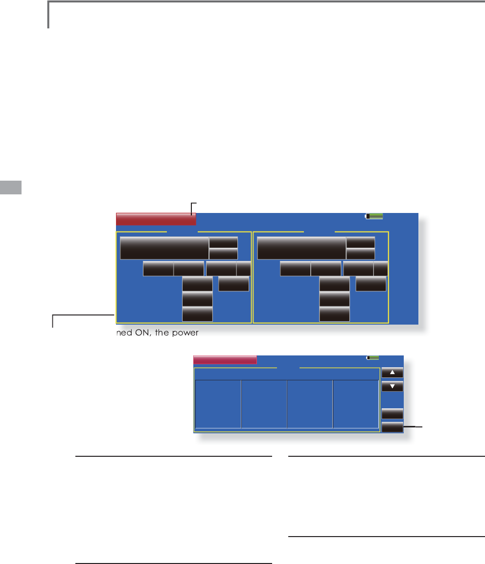
90 <Linkage Menu>
85%
Timer Model 1
Timer1
Mode
Start/Stop SW
Split Time SW
Memory
Up ؟
10
OFF OFF
OFF
OFF
00
Reset
OFF
00:00.0
ڂ
Timer2
Mode
Start/Stop SW
Split Time SW
Memory
Up ؟
10
OFF OFF
OFF
OFF
00
Reset
OFF
00:00.0
ڂ
85% 1 / 5
Model 1
Split Time
Return
Clear
Timer1
Lap# Split Time
1 00:00.0
2 00:00.0
3 00:00.0
4 00:00.0
5 00:00.0
6 00:00.0
Lap# Split Time
7 00:00.0
8 00:00.0
9 00:00.0
10 00:00.0
11 00:00.0
12 00:00.0
Lap# Split Time
13 00:00.0
14 00:00.0
15 00:00.0
16 00:00.0
17 00:00.0
18 00:00.0
Lap# Split Time
19 00:00.0
20 00:00.0
21 00:00.0
22 00:00.0
23 00:00.0
24 00:00.0
ŏ0HPRU\LVWXUQHG21WKHSRZHU
2))DQGDPRGHOFKDQ
J
HZLOOQRW
EHUHVHWWLPHU
HLWKHU
ŏ
7
RXFKWKH>7LPHU@EXWWRQLQWKH/LQND
J
H0HQXWR
F
DOOWKHVHWX
S
VFUHHQVKRZQEHORZ
Timer 7LPHUVHWWLQ
J
DQGODSWLPHGLVSOD\
T
h
e T
i
mer funct
i
on may
b
e set for any
d
es
i
re
d
t
i
me,
LHHQ
J
LQHUXQWLPHVSHFL¿HGWLPHVIRUFRPSHWLWLRQV
etc. Two independent timers are provided for your use.
T
h
e t
i
mers are store
d
i
n
d
epen
d
ent
l
y w
i
t
h
eac
h
mo
d
e
l
,
meanin
g
that when
y
ou switch between model setups,
the timer associated with the new model is brought up
a
utomat
i
ca
ll
y
.
T
h
e t
i
mers may
b
e set to start an
d
stop from t
he
mot
i
on of an
y
sw
i
tc
h
or st
i
c
k
. You ma
y
set t
h
e ON an
d
O
FF directions freel
y
. Each timer has a capacit
y
of up
to 5
9
m
i
nutes 5
9
secon
d
s
.
Up t
i
mer
/
Down t
i
mer select
i
on
7RXF
K
W
K
HPR
G
H
E
XWWRQDQ
G
VH
O
HFWW
K
HW\SH
RI
W
L
PHU
*
Each time this button is touched, it toggles between UP and
DOW
N.
7LPHUWLPHVHWWLQ
J
7RXF
KWK
H
0
RGH
PLQ
X
W
HV
R
U
VHFR
Q
GV
EX
WW
R
Q
$
G
M
XVWPHQWEXWWRQVDSSHDURQWKHVFUHHQ
8
VHWKHVHEXWWRQVWRVHWWKHWLPHUWLPH
S
tart
/S
Wtop sw
i
tch sett
i
ng
7RXF
K
W
K
H
6
WDUW
6
WRS
6
:
18//
E
XWWRQWRFD
OO
W
KH6Z
L
WFK!VFUHHQDQGWKHQVHOHFWWKH
V
Z
L
WFKDQG
L
WV21G
L
UHFW
L
RQ
)RUDGHWD
L
OHGGHVFU
L
SW
L
RQR
I
WKHVHOHFW
L
RQ
P
HWKRGVHH>6Z
L
WFK6HWW
L
QJ0HWKRG@DWWKH
E
DFNR
I
WK
L
VPDQXDO
Eac
h
t
i
mer may
b
e set for count-
d
own or count
up operation with a tar
g
et time. Also Split Time
m
ay be counted.
I
f a tar
g
et time is set and the timer reaches the se
t
ti
me, a
b
uzzer soun
d
for eac
h
count
i
s generate
d.
Countdown timers sound one short beep during the
l
ast twenty secon
d
s an
d
two s
h
ort
b
eeps
d
ur
i
ng t
h
e
l
ast ten secon
d
s
b
efore reac
hi
n
g
t
h
e tar
g
et, t
h
en a
l
on
g
t
one at the target time, and continue counting wit
h
di
sp
l
ay
i
ng a m
i
nus
(
-
)
s
i
gn. Count-up t
i
mers a
l
so
b
eep
th
e
l
ast twent
y
an
d
ten secon
d
s,
b
eep t
h
e tar
g
et t
i
me,
a
nd keep counting upwards until shut down
.
L
ap t
i
me sw
i
tch select
i
on
7RXF
K
W
K
H/DS
6
:
18//
E
XWWRQWRFD
OO
W
K
H
3
URJ0
L
[VFUHHQDQGWKHQVHOHFWWKHVZ
L
WFK
D
QG
L
WV21G
L
UHFW
L
RQ
)RUDGHWD
L
OHGGHVFU
L
SW
L
RQR
I
WKHVZ
L
WFK
V
HWW
L
QJPHWKRGVHH>6Z
L
WFK6HWW
L
QJ0HWKRG@
D
WWKHEDFNR
I
WK
L
VPDQXDO
T
imer operation
ŏ
7
L
PHUDQG7
L
PHUDUHVWDUWHGDQGVWRSSHG
E
\VWDUWVWRSVZ
L
WFKVHWEH
I
RUHKDQG
ŏ
7RFRXQWWKHODSW
L
PHRSHUDWHWKHODSW
L
PH
V
Z
L
WFKVHOHFWHGEH
I
RUHKDQG(DFKW
L
PHWK
L
V
V
Z
L
WFK
L
VRSHUDWHGWKHODSW
L
PH
L
VVWRUHG7R
GL
VSOD\WKHODSW
L
PHWRXFKWKHUHVSHFW
L
YH
>
/
L
VW@EXWWRQ
ŏ
7RUHVHWDW
L
PHUWRXFKWKHUHVSHFW
L
YH>5HVHW@
E
XWWRQ
7
RH[
L
WWKHVHWW
L
QJWRXFKWKH>7
L
PHU@EXWWRQ
ŏ5HWXUQWR7LPHU
VFUHHQ
<La
p
time list>
ŏ5HWXUQWR/
L
QNDJH0HQ
X
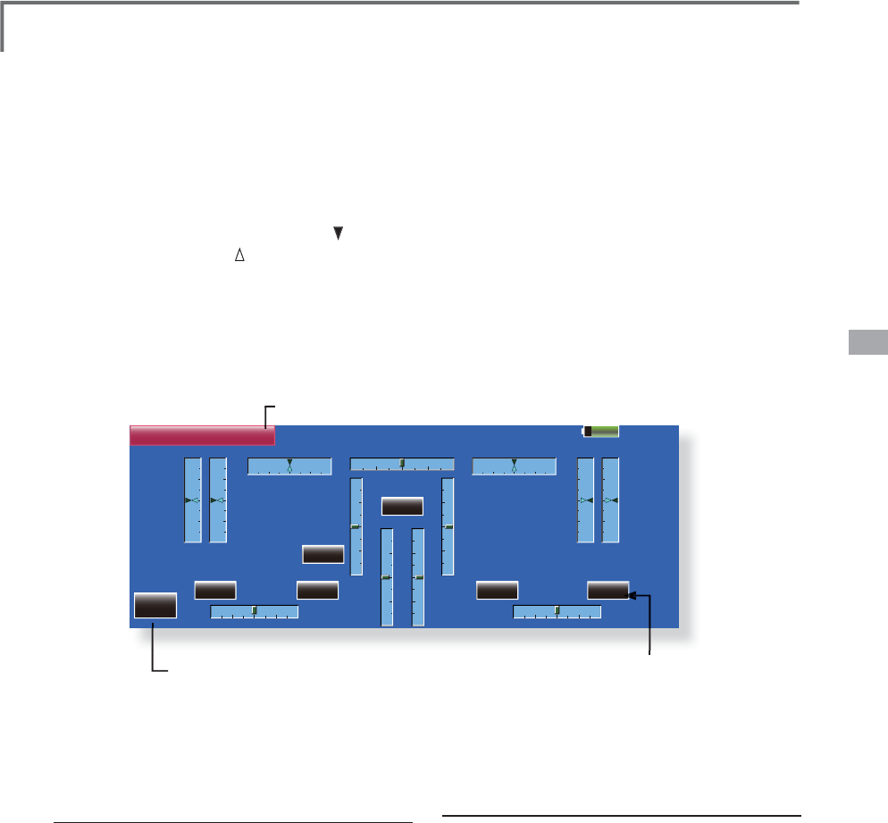
91
<Linkage Menu>
Model 1
Trim
Unit
LST
+0%
( +0%)
RST
+3%
( +3%)
LD
-11%
( -11%)
RD
-2%
( -2%)
LS
-2%
T6
+0
T5
+0
T4
+0
T1
+0
T3
+0
T2
+0
+2
( -2%)
RS
+0%
( +0%)
85%
Dial Monitor
Step
10
4 4 4 4
4
CD
Condition 1
ŏ5HWXUQWR/LQNDJH0HQ
X
ŏ7RXFKWKH>'LDO0RQLWRU@EXWWRQLQWKH/LQND
J
H
0HQXWRFDOOWKHVHWX
S
VFUHHQVKRZQEHORZ
ŏ7ULPFKDQ
J
HVIURPWKHVWHSWRGLVSOD\
Dial Monitor /'LVSOD\VWKHSRVLWLRQRIWKHGLDOVVOLGHUOHYHUVDQGGL
J
LWDOWULP
Di
g
ital trim position displa
y
(T1-T6, CD)
The Dial Monitor displays the current position
an
d
t
h
e operat
i
on step amount of eac
h
D
i
g
i
ta
l
Tr
i
m.
T
he trim step can be set directl
y
on the dial monitor
m
e
n
u.
V
R and sl
i
de lever pos
i
t
i
on d
i
splay
(
L
S
T, L
S
, LD,
RD, RS, RST)
Displa
y
s the current position (black ) and last
operating position (gree
n
)
of the VRs and slider
leve
r
s.
K
nob and Lever Pos
i
t
i
on d
i
spla
y
(
LD, RD, LS, LST, RS, RST)
T
he Dial Monitor displa
y
s the current position
an
d
l
ast operat
i
on pos
i
t
i
on of eac
h
k
no
b
an
d
l
ever.
A
l
t
h
ou
gh
ne
i
t
h
er
k
no
b
nor
l
ever can
h
o
ld
t
h
e
l
ast
operation position because of the
y
are “analo
g
”
type, t
h
e pos
i
t
i
on
d
ata
d
ur
i
ng t
h
e
l
ast operat
i
on
i
s
memor
i
ze
d
i
n t
h
e mo
d
e
l
memor
y
. B
y
mov
i
n
g
t
h
e
knob and lever to the position displa
y
ed on this
mon
i
tor, t
h
e
l
ast operat
i
on pos
i
t
i
on
i
s reca
ll
e
d
.
Recall
i
n
g
D
i
al Pos
i
t
i
on
(LST, LS, LD, RD, RS, RST)
T
he dial
p
osition data at the last o
p
eration is
di
sp
l
aye
d
for eac
h
k
no
b
an
d
l
ever
i
n t
hi
s mon
i
tor.
(Green arrow)
0RYHWKHEODFNDUURZ
FXUUHQWSRV
L
W
L
RQ
WRWKHJUHHQDUURZSRV
L
W
L
RQE\RSHUDW
L
QJ
WKHGHV
L
UHGNQRERUOHYHUWRUHFDOOWKHODVW
RSHUDW
L
QJSRV
L
W
L
RQ
D
i
g
ital trim step amount (T1-T6, CD)
Th
e tr
i
m step of t
h
e T1-T6 an
d
CD can
b
e set
di
rect
ly
on t
h
e
di
a
l
mon
i
tor menu.
ŏ
'L
J
LWDOWULPVWHSDPRXQW
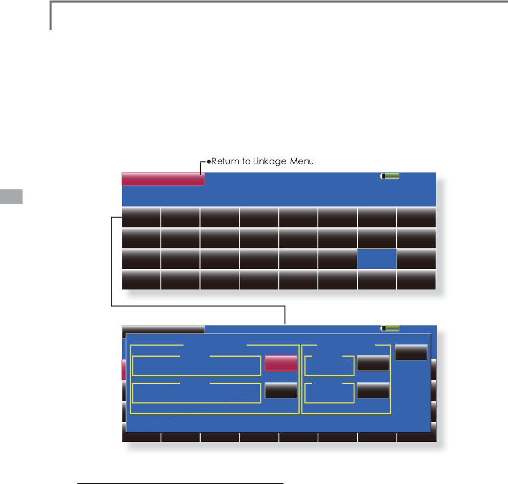
92 <Linkage Menu>
Please select a function.
85%
Function Name
Aileron Elevator Throttle Rudder Gear Flap Aileron2 Aileron3
Aileron4 Elevator2 Flap2 Air Brake Fuel-Mix Gyro Gyro2 Gyro3
Throttle2 Throttle3 Throttle4 Flap3 Flap4 Rudder2 Camber
Motor Auxiliary7 Auxiliary6 Auxiliary5 Auxiliary4 Auxiliary3 Auxiliary2 Auxiliary1
Close
Rename
Reset
Rename
Reset
10 Characters
Aileron
Current
Aileron
Default
AIL
Current
AIL
Default
4 Characters
ŏ7RXFKWKH>)XQFWLRQ1DPH@EXWWRQLQWKH/LQND
J
H
0HQXWRFDOOWKHVHWX
S
VFUHHQVKRZQEHORZ
Function Name )XQFW
L
RQ1DPHFDQEHFKDQJH
G
T
he setup screen can displa
y
functions names of up
WRF
K
DUDFWHUVDQ
G
X
S
WRF
K
DUDFWHUV
Procedure
f
or chang
i
ng the
f
unct
i
ons name
Select [Function Name] from the Linka
g
e Menu
.
Select the function whose name
y
ou want to
chan
g
e
.
Press the [Chan
g
e name] button and enter
the name in 1
0
characters and 4 characters
each from the displa
y
ed ke
y
board. After the
characters are entered, press the ke
y
board
[Return] ke
y
When the [Reset] ke
y
is pressed, the function
name is reset its ori
g
inal name
.
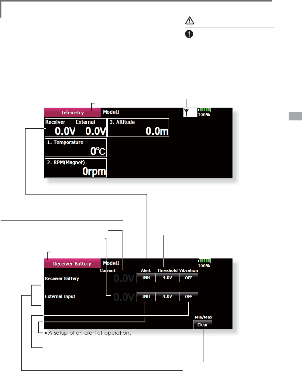
93
<Linkage Menu>
Telemetry
'
LVSOD\LQ
J
GDWDIURPWKHUHFHLYH
U
T
his screen displa
y
s the data from the receiver.
An a
l
arm can a
l
so
b
e generate
d
accor
di
ng to t
h
e
d
ata. For examp
l
e,
i
f t
h
e rece
i
ver vo
l
ta
g
e
d
rops, t
h
e
operator can be warned b
y
a transmitter alarm.
ŏ&DOOWKHIROORZLQ
J
VHWWLQ
J
VFUHHQE\SUHVVLQ
J
WKH
>7HOHPHWU\@EXWWRQRIWKH/LQND
J
H0HQX
ŏ,IYROWDJHIDOOVUDWKHUWKDQWKHYROWDJH
VHWX
S
KHUHWKHDODUPZLOOR
S
HUDWH
ŏ5HFHLYHU%DWWHU\YROWD
J
H
ŏ([WHUQDO,QSXWYROWD
J
H
(
([WUD9ROWD
J
HFRQQHFWRU
ŏ7KHGLV
S
OD
\
RIWKHPD[LPXP
D
Q
G
WK
H
PLQLP
X
P
>
&OHDU
@
LVUHVHWZLWKDPDOH
ŏ
,WR
S
HUDWHVE
\
,1+
→
21
2))
ŏ
$VHWX
S
RIYLEUDWLRQ
2
)
)
→
HDFKW
\S
HWKHYLEUDWLRQZLOOR
S
HUDWH
W
\S
HVWRVHOHFWLRQRIWKHNLQGRIYLEUDWLRQLV
S
RVVLEOH
ŏ5HWXUQWR/LQND
J
H0HQ
X
ŏ5HFHLYLQ
J
VWDWH
56%
→
70=
ŏ
5HWXUQWR7HOHPHWU
\
W
arning
Do not stare at the transmitte
r
V
FUHHQGXULQ
J
ÀL
J
KW
*You may loose sight of the aircraft during
À
L
J
KWDQGLVH[WUHPHO
\
GDQ
J
HURXV+DYH
t
he screen checked b
y
an assistant. The
p
il
ot s
h
ou
ld
not ta
k
e
hi
s e
y
es off t
h
e
a
i
r
c
raft
.
Receiver Battery Display
5.9V
5.0V - 6.4V
0.0V - 0.0V
0.0V
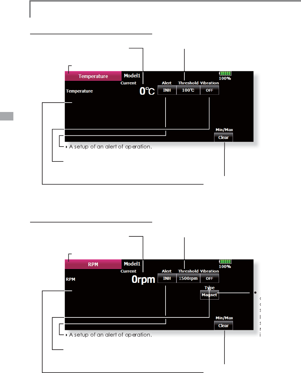
94 <Linkage Menu>
Temperature D
i
splay
RPM Display
ŏ7HPSHUDWXUHLVVHWXS:KHQLW
E
HFRPHVK
L
JKWHPSHUDWXUH
I
URPSUHVHW
W
HPSHUDWXUHW
K
HD
O
DUPRSHUDWHV
ŏ530LVVHWXS:KHQLWEHFRPHVKLJK
5
30
I
URPSUHVHW530WKHDODUP
R
SHUD
W
HV
ŏ
7HPSHUDWXUH'
L
VSOD\
ŏ
530'
L
VSOD\
ŏ
7KHG
L
VSOD\R
I
WKHPD[
L
PXP
D
QGWKHP
L
Q
L
PXP
>&OHDU@
L
VUHVHWZ
L
WKDPDOH
ŏ
7KHG
L
VSOD\R
I
WKHPD[
L
PXP
D
QGWKHP
L
Q
L
PXP
>&OHDU@
L
VUHVHWZ
L
WKDPDOH
6
H
O
HFWW
K
HW\SH
R
SW
L
FDOVHQVRU
R
UPDJQHW
L
F
VHQVRU
QRSW
L
FDO
V
HQVRUW
K
H
Q
XPEHUR
I
D
À
Q
LVLQSXWWHG
ŏ$VHWXSRIDQDOHUWRIRSHUDWLRQ
,WRSHUDWHV
E
\,1+
→
2
1
2
))
ŏ$VHWXSRIDQDOHUWRIRSHUDWLRQ
,WRSHUDWHV
E
\,1+
→
2
1
2
))
ŏ
$VHWXSR
I
Y
L
EUDW
L
RQ
2
))
→
HDFKW\SHWKHY
L
EUDW
L
RQZ
L
OORSHUDWH
W\SHVWRVHOHFW
L
RQR
I
WKHN
L
QGR
I
Y
L
EUDW
L
RQ
L
VSRVV
L
EOH
ŏ
$VHWXSR
I
Y
L
EUDW
L
RQ
2
))
→
HDFKW\SHWKHY
L
EUDW
L
RQZ
L
OORSHUDWH
W\SHVWRVHOHFW
L
RQR
I
WKHN
L
QGR
I
Y
L
EUDW
L
RQ
L
VSRVV
L
EOH
ŏ
5HWXUQWR7H
O
HPHWU\
ŏ5HWXUQWR7HOHPHWU\
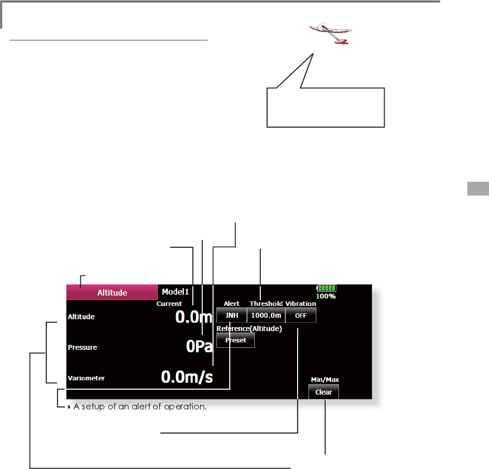
95
<Linkage Menu>
A
ltitude Display
ŏ$OWLWXGHLVVHWXS:KHQLWEHFRPHVKLJK
DOW
L
WXGH
I
URPSUHVHWDOW
L
WXGHWKHDODUP
RSHUD
W
HV
ŏ$OW
L
WXGH'
L
VSOD\
ŏ$WPRVSKHU
L
FSUHVVXUH'
L
VSOD\
ŏ9DU
L
RPHWHU'
L
VSOD
\
+RZPDQ\PHWHUU
L
VH
GHVFHQW
L
QVHFRQG
ŏ7KHG
L
VSOD\R
I
WKHPD[
L
PXP
DQGWKHP
L
Q
L
PXP
>&OHDU@
L
VUHVHWZ
L
WKDPDOH
ŏ$VHWXSRIDQDOHUWRIRSHUDWLRQ
,WRSHUDWHV
E
\,1+
→
2
1
2
))
ŏ
$VHWXSR
I
Y
L
EUDW
L
RQ
2
)
)
→
HDFKW\SHWKHY
L
EUDW
L
RQZ
L
OORSHUDWH
W\SHVWRVHOHFW
L
RQR
I
WKHN
L
QGR
I
Y
L
EUDW
L
RQ
L
VSRVV
L
EOH
ŏ5HWXUQWR7H
O
HPHWU\
Atmosp
h
er
i
c pressure
i
s measure
d
b
y a senso
r
a
n
d
an a
l
t
i
tu
d
e
i
s
j
u
dg
e
d
w
i
t
h
a
di
fference w
i
t
h
g
round atmospheric pressure.
Atmospheric pressure when the power suppl
y
o
f an altitude sensor is set to ON is displayed as a
stan
d
ar
d
(
0 m
)
.
[Preset] A
p
ush on a button will re-set u
p
a
s
tan
d
ar
d
a
l
t
i
t
ude.
Wh
at a
l
titu
d
e is it?
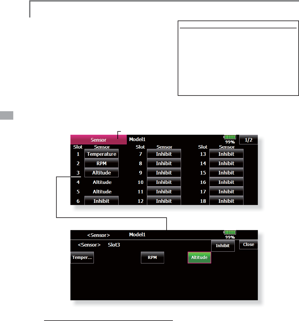
96 <Linkage Menu>
ŏ
5HWXUQWR/
L
QNDJH0HQX
ŏ7RXFKWKH>6HQVRU@EXWWRQLQWKH/LQND
J
H0HQXWR
FDOOWKHVHWX
S
VFUHHQVKRZQEHORZ
Sensor 9DU
L
RXVWHOHPHWU\VHQVRUVVHWW
L
QJ
P
rocedure for chan
g
in
g
the sensor of each slot No.
1
. Select [Sensor] from the Linka
g
e Menu.
2
. Select the sensor of the slot No. to be chan
g
ed.
3
. Select the t
y
pe of displa
y
ed sensor.
4
. When the [Yes] ke
y
is pressed, the t
y
pe of sensor is
c
han
g
ed.
*
In t
h
e case of t
h
e sensor w
hi
c
h
uses more s
l
ots,
i
t may
b
e una
bl
e
t
o ass
i
gn.
T
he telemetr
y
sensor slot No. and which sensor
i
s use
d
at eac
h
s
l
ot can
b
e c
h
ange
d
at t
hi
s screen.
S
ince the sensor at each slot is determined a
t
i
n
i
t
i
a
li
zat
io
n an
d
t
he
s
am
e
slo
t N
o.
is
m
e
m
o
r
i
z
ed
even for sensors sold separatel
y
, sensors can be
used by simply connecting them to S.BUS2. When
custom
i
z
i
ng t
h
e sensors yourse
l
f, perform sett
i
ng at
this screen.
[
What
i
s a slot
?]
S
ervos are c
l
ass
i
f
i
e
d
b
y CH,
b
ut sensors are
c
lassified in units called “slot”. There are slots
f
rom No. 1 to No. 31.
A
ltitude sensor and other voluminous data
sensor units use multi
p
le slots.
W
hen 2 or more of the same kind of sensor
a
re use
d,
t
h
e sensors t
h
emse
l
ves must a
ll
ocate
u
n
used
slo
t
s
an
d
m
e
m
o
r
i
z
ed
t
he
a
lloc
at
ed
slo
t
.
*
Three slots of altitude sensor are used.
S
lo
t
FDQQRWEHXVHGIRUDQDOWLWXGHVHQVRU
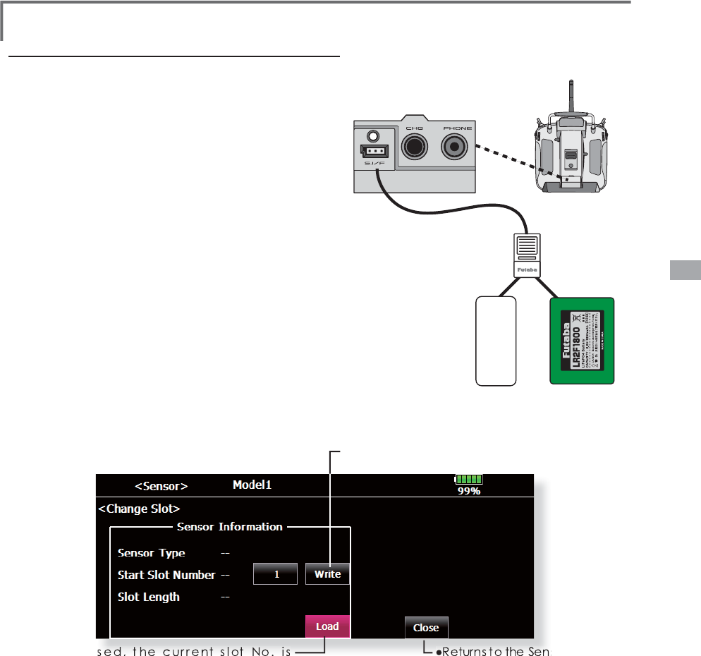
97
<Linkage Menu>
Procedure
f
or chang
i
ng the slot No. o
f
each sensor un
i
t
1
. Se
l
ect
[
Sensor
]
on pa
g
e 2 o
f
t
h
e Lin
k
a
g
e Menu
.
2. Ca
ll
pa
g
e 2
by
pressin
g
[
1
/
2
]
an
d
press
[
C
h
an
g
e S
l
ot
]
.
3. Connect t
h
e receiver
b
attery an
d
t
h
e sensor unit to t
h
e S.I
/
F
c
onnector
b
e
h
in
d
t
h
e rear cover o
f
t
h
e transmitter usin
g
a 3-wa
y
h
u
b
or 2-wa
y
cor
d.
4. Press t
h
e
[
Rea
d]
k
ey. T
h
e current s
l
ot No. is
d
isp
l
aye
d.
5. When a number is pressed, the [ 䂦], [ 䂰], [ 䂦䂦 ] and [ 䂰䂰 ]
k
eys appear. Now change the desired No.
6. When the [Write] key is pressed, the desired No. is written to the
sensor
ŏ&DOOWK
L
VVFUHHQE\VZ
L
WFK
L
QJWRSDJHE\
SUHVV
L
QJWKH>@EXWWRQRQWKH6HQVR
U
VFUHHQDQGWKHQSUHVV
L
QJ>&KDQJH6ORW@
ŏ:KHQSUHVVHGWKHFXUUHQWVORW1RLV
G
L
VSOD\HG
ŏ7KHVORW1R
L
VZU
L
WWHQWRWKHVHQVRU
V
RUVFUHHQ
Sensor
HUB
or Y-adapter
Receiver battery
T18MZ
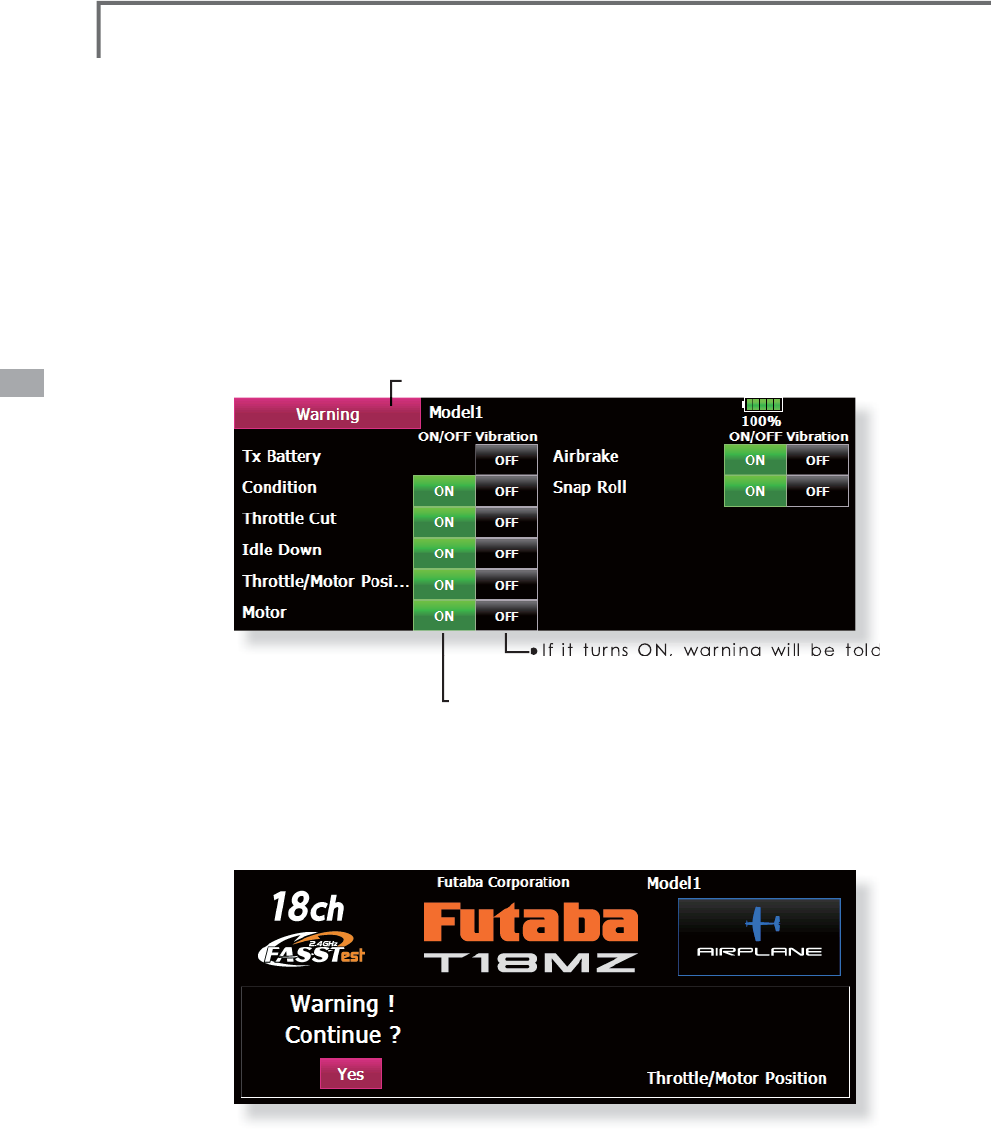
98 <Linkage Menu>
ŏ
5HWXUQWR/
L
QNDJH0HQX
ŏ,ILWWXUQV21ZDUQLQJZLOOEHWROGZLWK
YL
EUDW
L
RQ
ŏ,
I
L
WFKDQJHVDW2))DODUPVWRSVFRP
L
QJRXW
DWWKHW
L
PHR
I
WKHSRZHUVXSSO\21
ŏ
,
I
DWKURWWOHVW
L
FNXVHVWKHSRZHUVXSSO\21
L
QWKHVWDWHE\WKHV
L
GHR
I
D
KL
JKWKHQH[WVFUHHQZ
L
OOFRPHRXWDQGDODUPZ
L
OOVRXQG
7KHWKURWWOHVW
L
FNVKRXOGWXUQRQDSRZHUVXSSO\
L
QWKHVWDWHE\WKHV
L
GHR
I
D
O
RZDWDQ\FRVW
ŏ
,
I
DWKURWWOHVW
L
FN
L
VORZHUHGDODUPZ
L
OOVWRSDQG
L
WZ
L
OOEHFRPHD
FRQ
À
UPDW
L
RQVFUHHQ,WVWDUWVE\<(6
ŏ
7RXFKWKH>:DUQ
L
QJ@EXWWRQ
L
QWKH/
L
QNDJH0HQX
W
RFD
OO
W
K
HVHWXSVFUHHQV
K
RZQ
E
H
O
RZ
Warning 6HWWLQ
J
RIZDUQLQ
J
VRXQGDQGYLEUDWLRQ
*
If a t
h
rott
l
e st
i
c
k
turns on a power power supp
ly
in the hi
g
h state in case of the electric bod
y
, i
t
may
b
eg
i
n to turn to
hi
g
h
rotat
i
on su
dd
en
l
y, an
d
i
s ver
y
d
an
g
erous. We recommen
d
y
ou to use t
h
e
w
arnin
g
of a throttle position with ON. Please
b
e sure to turn on eac
h
power supp
l
y
i
n t
h
e state
wh
ere a t
h
rott
l
e st
i
c
k
i
s s
l
ow.
Warning when a power supply is turned on can
b
e set up for every funct
i
on. A
ll
i
n
i
t
i
a
l
sett
i
ng
i
s
ON. Please turn ON the function in which it seems
t
hat it is dangerous in accordance with the purpose
of use. A
l
arm
i
s stoppe
d
i
f t
h
e funct
i
on of eac
h
i
tem is o
p
erated at OFF.

99
<Linkage Menu>
Model 1 Condition 1 85%
Date Reset
Direct Key Model Menu Setting All Model SettingT1~T6, CD
Function Name
ŏ
5HWXUQWR/LQNDJH0HQX
ŏ7RXFKWKH>'DWD5HVHW@EXWWRQLQWKH/LQND
J
H0HQX
WRFDOOWKHVHWX
S
VFUHHQVKRZQEHORZ
Data Reset
0
RGHOPHPRU\VHWWLQ
J
GDWDUHVHW
E\LWHP
This function is desi
g
ned to allow
y
ou to reset
se
l
ecte
d
port
i
ons or a
ll
of t
h
e sett
i
ngs save
d
i
n
th
e act
i
ve mo
d
e
l
memor
y
. You ma
y
i
n
di
v
id
ua
lly
choose to reset the followin
g
sets of data;
T1~T6
,
CD:
R
eset the digital trim setting.
*
A
ll
t
h
e con
di
t
i
ons, or t
h
e con
di
t
i
on current
l
y
b
e
i
ng
di
sp
l
aye
d
(
t
h
e ent
i
re group for group sett
i
ng
)
, can
b
e se
l
ecte
d
.
D
irect ke
y
:
Resets direct ke
y
assi
g
nment.
D
ata Resett
i
ng
7RXFKWKHGHV
L
UHGEXWWRQWRUHVHWWKHVHWR
I
G
DWD
3HU
I
RUPWKHGDWDUHVHWW
L
QJDFFRUG
L
QJWRWKH
L
QVWUXFW
L
RQVG
L
VSOD\HGRQDVFUHHQ:KHQ
FRPS
O
HWHWRXF
K
W
K
H'DWD5HVHW
E
XWWRQWR
H[
L
W
M
odel menu settin
g
:
R
esets all the functions in the Model Menu
e
xce
p
t Condition Select.
All model sett
i
ng:
R
esets a
ll
L
i
n
k
age an
d
Mo
d
e
l
Menu funct
i
ons
e
xcept for S
y
atem T
y
pe, Mo
d
e
l
Se
l
ect, an
d
Mo
d
e
l
T
ype.
I
n
itial settin
g
of a motor channel is reverse.
A
ft
e
r r
ese
t
is
r
eve
r
se.

100 <Linkage Menu>
Condition Hold &RQGLWLRQKROGIXQFWLRQ+HOLFRSWHURQO\
7KLVIXQFWLRQPD\EHXVHGWR¿[WKHPD[LPXP
speed of the engine so that you may adjust flight
conditions when the engine is running. An alarm
indicates that the function is operating. It will
prevent the engine from racing dangerously when
adjusting the Idle-Up settings.
While this function is active, the throttle servo
position is fixed at the point where you operate
when the function is activated. You must deactivate
this function when you are through making
adjustments.
The system will not allow you to activate/
deactivate this function in either of the following
states:
:KHQDQ\RIWKHIOLJKWFRQGLWLRQVZLWFKHV
DUHRQ
:KHQWKHWKURWWOHVWLFNLVKLJKHUWKDQWKH
SRLQW
To activate/deactivate Condition hold:
(Home screen)
6HWWKHWKURWWOHVWLFNORZHUWKDQWKHSRLQW
3XVKWKHGLUHFWNH\6&RQG+ROGWR
DFWLYDWHWKHFRQGLWLRQKROGIXQFWLRQ
*When this function is active, "Condition Hold is active"
appears on the screen.
(LINKAGE menu/MODEL menu)
6HWWKHWKURWWOHVWLFNORZHUWKDQWKHSRLQW
3XVKWKH,1+RUWKHGLUHFWNH\6EXWWRQWR
DFWLYDWHWKHFRQGLWLRQKROGIXQFWLRQ
*Operation is displayed at the bottom of the menu.
Function ON: "ON" is displayed.
Function OFF: "INH" is displayed.