Contents
- 1. User manual-1(page 1-30)
- 2. User manual-2(Page 31-100)
- 3. User manual-3(Page 101-162)
User manual-3(Page 101-162)
101
<Model Menu (Common Functions)>
MODEL MENU (COMMON FUNCTIONS)
System Menu Linkage Menu Model Menu Return
Model 1 Condition 1 85%
Model Menu
Condition Select AFR ( D/R ) Prog. Mixes
Flap Setting AIL to CamberFLP
Airbrake to ELE ELE to Camber
RUD to AIL
$,/'LíHUHQWLDO
Servo Monitor
AIL to RUD
CamberFLP to ELE
Camber Mix
1/2
AIL to Brake FLP
RUD to ELE Snap Roll
T
his section describes the AFR, pro
g
ram mixin
g
,
an
d
ot
h
er funct
i
ons common to a
ll
mo
d
e
l
types.
Before setting the model data, use the Model
T
ype funct
i
on of t
h
e L
i
n
k
age Menu to se
l
ect t
h
e
mo
d
e
l
t
y
pe matc
h
e
d
to t
h
e fuse
l
a
g
e. W
h
en anot
h
er
model type is selected thereafter, the AFR, program
m
i
x
i
ng, an
d
ot
h
er sett
i
ng
d
ata are reset.
T
h
e
f
u
n
c
ti
o
n
s
in th
e
M
ode
l M
e
n
u
c
an
be
se
t f
o
r
eac
h
f
li
g
h
t con
di
t
i
on. W
h
en you want to use t
h
e
sy
stem b
y
switchin
g
the settin
g
s for each condition
b
y switch, stick position, etc., use the Condition
Se
l
ect funct
i
on to a
dd
f
li
g
h
t con
di
t
i
ons.
(
Up to 8
conditions can be used)
Note: The T18MZ
i
s des
i
gned so that the a
i
rplane
and gl
i
der
(i
nclud
i
ng EP gl
i
der
)
model types are
compatible with fuselages of similar type wings.
This section outlines the relationshi
p
between the
f
unctions common to airplanes and gliders, except
s
ome dedicated functions, and model type.
The settin
g
items depend on the number of servos
and other d
iff
erences accord
i
n
g
to the w
i
n
g
type
used, but reread them. The setup screens
i
n the
i
nstruct
i
on manual are typ
i
cal examples.
ŏ5H
W
XUQ
W
R+RPHVFUHH
Q
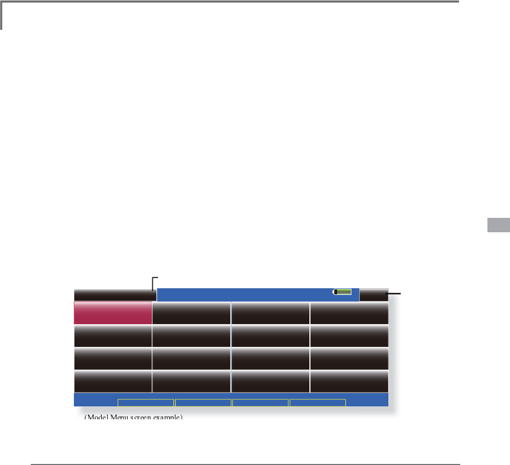
ŏ7RXFKWKH0RGHO0HQXEXWWRQR
I
WKH+RPHVFUHHQWRFDOOWKH
Mo
d
e
l
Menu
.
ŏ:KHQWKHEXWWRQR
I
WKH
I
XQFW
L
RQ\RXZDQWWRVHW
L
VWRXFKHGD
se
t
up screen appears
.
(Model
Menu
screen
example)
*The Model Menu screen depends on the model t
y
pe. This screen is for model t
y
pe 4AIL+4FLP.
ŏ7RQH[WSDJH
M
odel Menu functions (Common) list
Ɣ6
HUYR0RQLWRU
Servo test and servo position displa
y
(For a
d
escription of its functions, see the Linkage Menu
sect
i
on.
)
Ɣ&
RQGLWLRQ
6
HOHFW
Fli
g
ht conditions addition, deletion, cop
y
,
condition renaming, and condition delay can be set.
Ɣ
$)5
'
5
Sets t
h
e ru
dd
er ang
l
e an
d
curve of a
ll
t
h
e
operat
i
on funct
i
ons. A D
/
R curve w
hi
c
h
can
b
e
switched with a switch, etc. can also be added.
Ɣ
3UR
J
0L[H
V
Pro
g
ram mixin
g
which can be freel
y
customized.
U
p
to 10 mixes can be used for each condition.
Ɣ
)
XH
O0
L
[W
X
U
H
M
i
x
i
ng use
d
i
n nee
dl
e a
dj
ustment of eng
i
nes
w
hi
c
h
use a fue
l
m
i
xture contro
l
car
b
uretor.
[Air
p
lane, helico
p
ter]
102 <Model Menu (Common Functions)>
85%
Model 1 Condition 1
Condition Select
1
Condition List
Condition 1
Add Delay Copy Rename
Priority
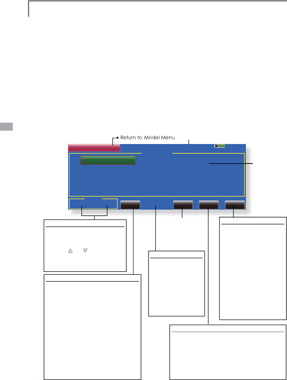
ŏ7RXFKWKH>&RQG
L
W
L
RQ6HOHFW@EXWWRQ
L
QWKH0RGHO
Menu to ca
ll
t
h
e setup screen s
h
own
b
e
l
ow
.
Condition Select Fli
g
ht conditions addition, deletion, copy, condition renamin
g
, and condition
GHOD
\
FDQEHVHW
>
$OOPRGHOW
\S
HV
@
The functions in the Model Menu can be used b
y
sw
i
tc
hi
ng t
h
e sett
i
ngs of up to 8 f
li
g
h
t con
di
t
i
ons
E\
XV
L
Q
J
W
K
H&RQ
GL
W
L
RQ6H
O
HFWIXQFW
L
RQWRD
GG
ÀLJKW
c
onditions. Add conditions, as re
q
uired.
W
h
en
y
ou
d
o not want to use t
h
e Con
di
t
i
on
S
elect function, this settin
g
is unnecessar
y
. In
thi
s case, use t
h
e f
li
g
h
t con
di
t
i
ons
(
Con
di
t
i
on 1
)
a
ss
ig
ne
d
at
i
n
i
t
i
a
l
sett
i
n
g
.
ŏ
6
L
QFHVZ
L
WFK
L
QJE\VW
L
FNDQGOHYHUSRV
L
W
L
RQ
L
Q
a
dd
i
t
i
on to ord
i
nary toggle sw
i
tch,
i
s poss
i
ble
a
s the
f
l
i
ght cond
i
t
i
on selector sw
i
tch, th
i
s
I
XQFW
L
RQFDQEHO
L
QNHGZ
L
WKRWKHURSHUDW
L
RQV
ŏ
$&RQG
L
W
L
RQ'HOD\
I
XQFW
L
RQFDQEHVHW
U
nnecessary
f
uselage mot
i
on generated
w
hen there are sudden changes
i
n the servo
p
os
i
t
i
ons and when there are var
i
at
i
ons
i
n
t
he operat
i
ng t
i
me between channels dur
i
ng
c
ond
i
t
i
on sw
i
tch
i
ng can be suppressed. The
d
elay can be set
f
or each channel
.
:
KHQVHWW
L
QJWKHGHOD\
I
XQFW
L
RQDWWKH
s
w
i
tch
i
ng dest
i
nat
i
on cond
i
t
i
on, the
r
elated
f
unct
i
on changes a
f
ter a delay
c
orrespond
i
ng to the set amount
.
ŏ
:KHQPXOW
L
SOHFRQG
L
W
L
RQVZHUHVHWWKH
L
U
o
perat
i
on pr
i
or
i
ty can be
f
reely changed
.
ŏ
7KHFRQG
L
W
L
RQQDPHFDQEHFKDQJHG7KH
s
elected cond
i
t
i
on name
i
s d
i
splayed on
W
KHVFUHHQ:KHQDFRQG
L
W
L
RQKDVEHHQ
a
dded, g
i
ve
i
t a name wh
i
ch can be eas
i
ly
F
RQ
À
UPHG
(Conditions List)
3U
L
RU
L
W
\
FKDQ
JH
1
. Touch the condition whose
p
riorit
y
\
RXZDQWWRFKDQJH
L
Q&RQG
L
W
L
RQV
L
is
t
.
&KDQ
J
HWKHSULRULW\ZLWKWKH
S
ULRULW
\
>
@
RU
>
@EXWWRQ
7KHODVW
cond
i
t
i
on has the h
ig
hest pr
i
or
i
ty.
)
*The initial setting condition cannot be
moved. It has the lowest priority.
&
RQGLWLRQ$GGLWLRQ
:KHQWKH>$GG@EXWWRQLV WRXFKHGWKH
&RQGLWLRQ6HOHFWVFUHHQD
SS
HDUV
*
On
l
y t
h
e num
b
er of
b
uttons correspon
di
ng to t
h
e
c
on
di
t
i
ons w
hi
c
h
can
b
e a
dd
e
d
are
di
sp
l
aye
d
.
6HOHFWWKHGHVLUHGFRQGLWLRQVE\ WRXFKLQ
J
th
e
b
uttons.
*
The selected conditions are added to
C
onditions
Li
s
t
.
7RXFKWKH>18//@EXWWRQWRFDOOWKH
6
ZLWFK!VFUHHQ
6HOHFWWKHVZLWFKWREHXVHGLQFRQGLWLRQ
sw
i
tch
i
ng
.
(
For a
d
escr
i
pt
i
on of t
h
e sw
i
tc
h
se
l
ect
i
on met
h
o
d
,
s
ee next pa
g
e.
)
7KH
&
RQGLWLRQGDWDIRUWKHDGGHG
c
onditions is co
p
ied
.
&
RQG
L
W
L
RQ5HVHW
6HOHFWWKHFRQGLWLRQ
by touch
i
ng the
c
ond
i
t
i
on you want to
U
HVHW
L
Q
&
RQG
L
W
L
RQV/
L
VW
7RXF
K
W
K
H
>
5HVHW
@
bu
tt
o
n
.
:KHQWKH><HV@EXWWRQ
i
s touched, the
c
ondition is reset.
(
To
a
bort resettin
g
, touch
W
KH>1R@EXWWRQ
&RQGLWLRQ5HQDPLQ
J
6HOHFWWKHFRQGLWLRQE
\
touching the condition
y
ou want to rename
i
n
&RQG
L
W
L
RQV/
L
VW
7RXF
K
W
K
H
>
5HQDPH
@
E
XWWRQ
3
. Enter the new name
f
rom
WKHNH
\
ERDUGZK
L
FK
appears on the screen.
(
For
a descr
i
pt
i
on o
f
the method
o
f
us
i
n
g
the Japanese
l
an
g
ua
g
e conversion
PR
G
HVHH
&K
DUDFWHUV
In
p
ut Method" of the Basic
O
peration section.)
:KHQWKHNH\ERDUG>5HWXUQ@
NH\
L
VWRXFKHGWKHQH
Z
name is re
g
istered.
(
To
abort re
g
istration, touch the
>(6&@NH\
&RQGLWLRQ&RS
\
7RXF
K
W
K
H
>&
R
S\@
E
XWWRQ7
K
H
&
R
S\
VFUHHQD
SS
HDUV
6HOHFWWKHFRQG
L
W
L
RQE\WRXFK
L
Q
J
WKHEXWWRQR
I
WKH
copy source cond
i
t
i
ons
.
3. Next, select the condition by touching the copy
des
t
i
n
a
t
io
n
co
n
di
t
io
n
.
7RXFKWKH>&23<@EXWWRQ
:KHQWKH
>
<HV
@
EXWWRQLVWRXFKHGWKHGDWDLV
FRS
L
HG
7RDERUWFRS\
L
QJWRXFKWKH>1R@EXWWRQ
(
Current
ly
se
l
ecte
d
con
di
t
i
on name
)
ŏ
&RQG
L
W
L
RQGHOD
\
s
ett
i
ng
(
For a
d
escr
i
pt
i
on of
th
e sett
i
ng met
h
o
d
,
see t
h
e next page.
)
103
<Model Menu (Common Functions)>
ŏ5HWXUQWR&RQG
L
W
L
RQ
6
H
O
HFWVFUHH
Q
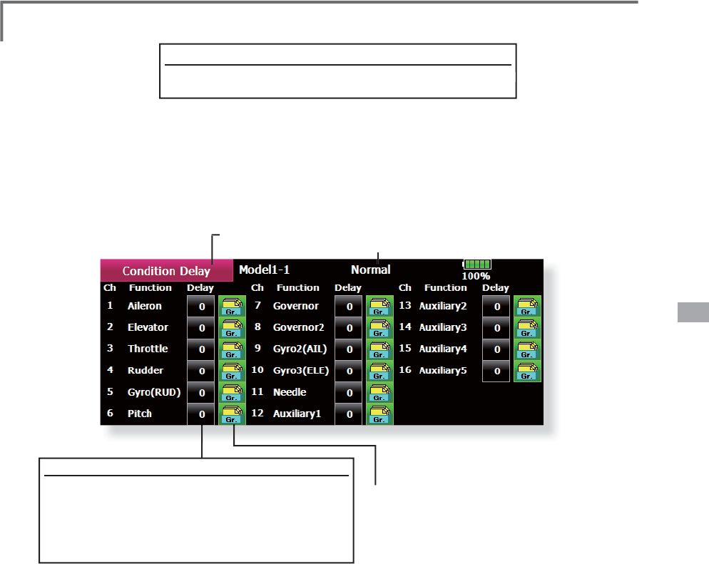
ŏ7RXFKWKH>'HOD\@EXWWRQRQWKH&RQG
L
W
L
RQ
6HOHFWVFUHHQWRFDOOWKH&RQG
L
W
L
RQ'HOD\
screen s
h
own
b
e
l
ow
.
(Currentl
y
selected condition name)
&RQGLWLRQGHOD
\
VHWWLQ
J
6ZLWFKWRWKHFRQGLWLRQ
\
RXZDQWWRVHW
7RXFKWKH'HOD\EXWWRQR
I
WKHFKDQQHO\RXZDQWWRVHW
3
. Use the adjustment buttons to set the delay
.
ŏ,Q
L
W
L
DOYDOXH
ŏ$G
M
XVWPHQWUDQ
J
Ha
PD[LPXPGHOD\
ŏ*URXSVLQJOHPRGHVZLWFKLQJ*U6QJO
(For a description of the operation method, see the
d
escr
i
pt
i
on at t
h
e
b
ac
k
of t
hi
s manua
l
.
)
&
RQG
L
W
L
RQVZ
L
WFKVHWW
L
QJDQG21
2))G
L
UHFW
L
RQVZ
L
WFK
L
QJ
*
For a
d
escr
i
pt
i
on of t
h
e se
l
ect
i
on met
h
o
d
, see [Sw
i
tc
h
Sett
i
ng Met
h
o
d
] a
t
th
e
b
a
c
k
o
f thi
s
man
u
al
.
t
104 <Model Menu (Common Functions)>
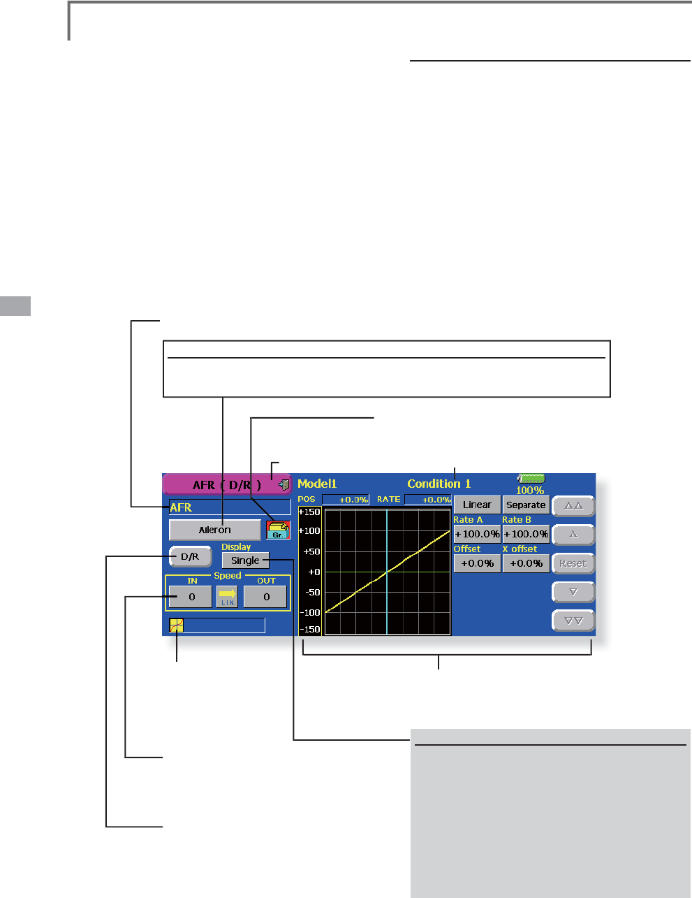
ŏ5HWXUQWR0R
G
H
O
0HQ
X
ŏ7RXFKWKH>$)5'5@EXWWRQLQWKH0RGHO0HQXWRFDOO
t
h
e setup screen s
h
own
b
e
l
ow
.
$)5'5
7
KHUXGGHUDQ
J
OHDQGFXUYHRIHDFKRSHUDWLRQIXQFWLRQFDQEHVHW$'5FXUYH
Z
KLFKFDQEHVZLWFKHGE
\
VZLWFKHWFFDQDOVREHDGGHG
>
$OOPRGHOW
\S
HV
@
A
FR funct
i
on
i
s use
d
to a
dj
ust t
h
e t
h
row an
d
op
eration curve of the stick, lever, and switch
IXQFWLRQV&+WR&+IRUHDFKÀLJKWFRQGLWLRQ
T
hi
s
i
s norma
ll
y use
d
after En
d
Po
i
nt
(
ATV
)
h
as
GH¿QHGWKHPD[LPXPWKURZGLUHFWLRQV(QG3RLQW
a
cts on ALL flight condition settings). When
mi
x
i
ng
i
s app
li
e
d
from one c
h
anne
l
to anot
h
e
r
c
hannel, both channels can be ad
j
usted at the same
t
ime by adjusting the operation rate through the
A
FR f
u
n
c
t
io
n
.
6HWWLQ
J
PHWKRG
ŏ2SHUDWLRQFXUYHDG
M
XVWPHQW6L[W\SHVRI
FXUYHV
OLQHDU(;3(;3975OLQHDQG
VSOLQH
FDQEHVHOHFWHG$PD[LPXP
p
oints curve can be used for the line and
spline curve types.
(
Initial settin
g
: 9 points
)
The number of
p
oints can also be increased
and decreased and curves from com
p
le
x
curves to sim
p
le curves can be used
.
ŏ2SHUDWLRQVSHHGDG
M
XVWPHQW7KHRSHUDWLRQ
s
p
eed of each function when the function
is operated
(
includin
g
at fli
g
ht condition
switchin
g)
can be ad
j
usted. The function
o
p
erates smoothl
y
at a constant s
p
eed
correspondin
g
to the set speed
.
(
Current
ly
se
l
ecte
d
con
di
t
i
on name
)
(
Current
ly
se
l
ecte
d
rate name: AFR, D
/
R1~6
)
F
u
n
c
t
io
n
se
l
ec
t
io
n
:KHQWKH
I
XQFW
L
RQVHOHFWEXWWRQ
L
VWRXFKHGDVHOHFW
L
RQVFUH
HQ
DSSHDUV
6HOHFWWKHIXQFWLRQ\RXZDQWWRVHWDWWKHVHOHFWLRQVFUHHQ
(
Total number of AFR
and D/R curves set at
t
he currentl
y
selecte
d
condition)
ŏ6HUYRVSHHGVHWWLQ
J
(
For a description of the settin
g
method,
s
ee the descri
p
tion at the back of this
manua
l
.
)
ŏ'5
I
XQFW
L
RQVHWW
L
Q
J
6
FUHHQPRGHVZ
L
WFK
L
QJ
W
h
en sett
i
ng t
h
e D
/
R funct
i
on, t
h
e screen
di
sp
l
a
y
mo
d
e can
b
e c
h
an
g
e
d
. Eac
h
t
i
me t
h
e
button is touched, the mode is switched.
>6QJO@
L
Q
L
W
L
DOVHWW
L
QJ
2QO\WKHFXUUHQWO\
operat
i
ng curve
i
s d
i
splayed
.
7
K
H$)5DQ
G
'
5FXUYHVVHWDWW
K
HFXUUHQW
O
\
operat
i
ng cond
i
t
i
on are d
i
splayed
.
>
$
OO
&
RQ
G
@
7
K
H$)5FXUYHVHWDWD
OO
cond
i
t
i
ons
i
s d
i
splayed
.
ŏ*URXSV
L
QJOHPRGHVZ
L
WFK
*U6QJO
(For more information, see the descri
p
tion at the back of this manual.)
ŏ2SHUDWLRQFXUYHVHWWLQ
J
(For a description of the setting method, see the description at the
back of this manual.
)
105
<Model Menu (Common Functions)>
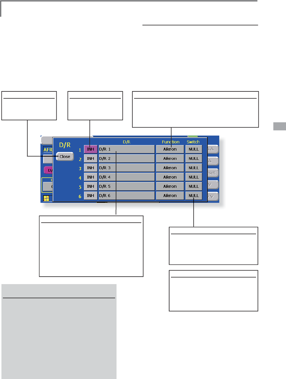
'XDO5DWHVHWW
L
Q
J
U
p to 6
d
ua
l
rates can
b
e set for eac
h
con
di
t
i
on.
*D/R
(
Dual Rate
)
is set for each condition, and is no
t
UHÀHFWHGDWRWKHUFRQGLWLRQV
*D/R (Dual Rate) at the top of the D/R list has priority.
6
HWWLQJPHWKR
G
ŏ7RXFKWKH>'5@EXWWRQ
I
URPWKH$)5
'5
screen o
f
the
f
unct
i
on
(
a
i
lerons, elevators,
etc.
)
whose dual rate you want to set. The
'5O
L
VWVFUHHQVKRZQEHORZ
L
VG
L
VSOD\HG
Touch the
(f
unct
i
on
)
button o
f
the dual
rate number to be ass
i
gned. That rate
i
s
automat
i
cally ass
i
gned to that
f
unct
i
on
.
ŏ1H[WVHOHFWWKHVZ
L
WFKDQG
L
WV212))
d
i
rect
i
ons
.
C
lose
ŏ$WWK
H
H
Q
G
R
I
HDF
K
settin
g
, touch the
>
&ORVH
@
EXWWRQ
6
WDUW'
5
ŏ
7RVWDUW'
5WRXFK
W
KH
>
,1+
@
EXWWRQ
)XQFW
L
RQFKDQ
J
H
ŏ
:KHQWKHDLOHURQEXWWRQLVWRXFKHGWKHV
\
VWHP
D
VNVIRUD><HV@RU>1R@7RFKDQ
J
HWKHIXQFWLRQ
V
ZLW
F
KW
R
WK
H
I
X
Q
F
WL
R
Q
VH
O
HF
W
HG
D
WWK
H
$)5
V
FUHHQE\DQVZHULQ
J
><HV@
1DPLQJ'5
7RQDPH'
5WRXF
K
W
K
H
>
'
5
@
E
XWWRQ$
N
H\
E
RDU
G
DSSHDUVRQW
K
H
screen.
2. Enter the des
i
red name
f
rom th
i
s
NH\ERDUGDQGUHJ
L
VWHU
L
WE\WRXFK
L
QJ
W
K
H
N
H\
E
RDU
G
>
5HWXUQ
@
N
H\7RFDQFH
O
i
nput and close the screen, touch the
>
(
6&@
N
H\
6
Z
L
WFKVHWW
L
Q
J
7RXFKWKH
>
18//
@
EXWWRQ7KH
6ZLWFK!VFUHHQD
SS
HDUV
6HOHFW
FRQÀUP
WKHVZLWFKDQG
its
O
N direction
.
6HWWLQJH[DPSOH
ŏ5XGGHU212))E\VZ
L
WFK
:KHQ'5
L
VXVHGE\XV
L
QJWKH
cond
i
t
i
on w
i
th the same sw
i
tch,
anot
h
er ru
dd
er ang
l
e can
b
e set
.
6
LQFHWKHIXQFWLRQVKRZQEHORZLVXVHGE\DQ
H[FOXV
L
YH
I
XQFW
L
RQ$)5
'
5
FDQQRWEHFKRVHQ
$
LOHURQ
$LOHURQ
$LOHURQ
F
la
p
2,Fla
p4
5XGGH
U
T
hrottle
(
Only helicopter
)
P
it
ch
&
DPEHU
*
\UR
58'
*\UR
$,/
*\UR
(/(
*
RYHUQRU
M
ixt
u
r
e
E
l
e
v
a
t
o
r
2
%
XWWHUÁ
\
106 <Model Menu (Common Functions)>
ŏ
5HWXUQWR0R
G
H
O
0HQX
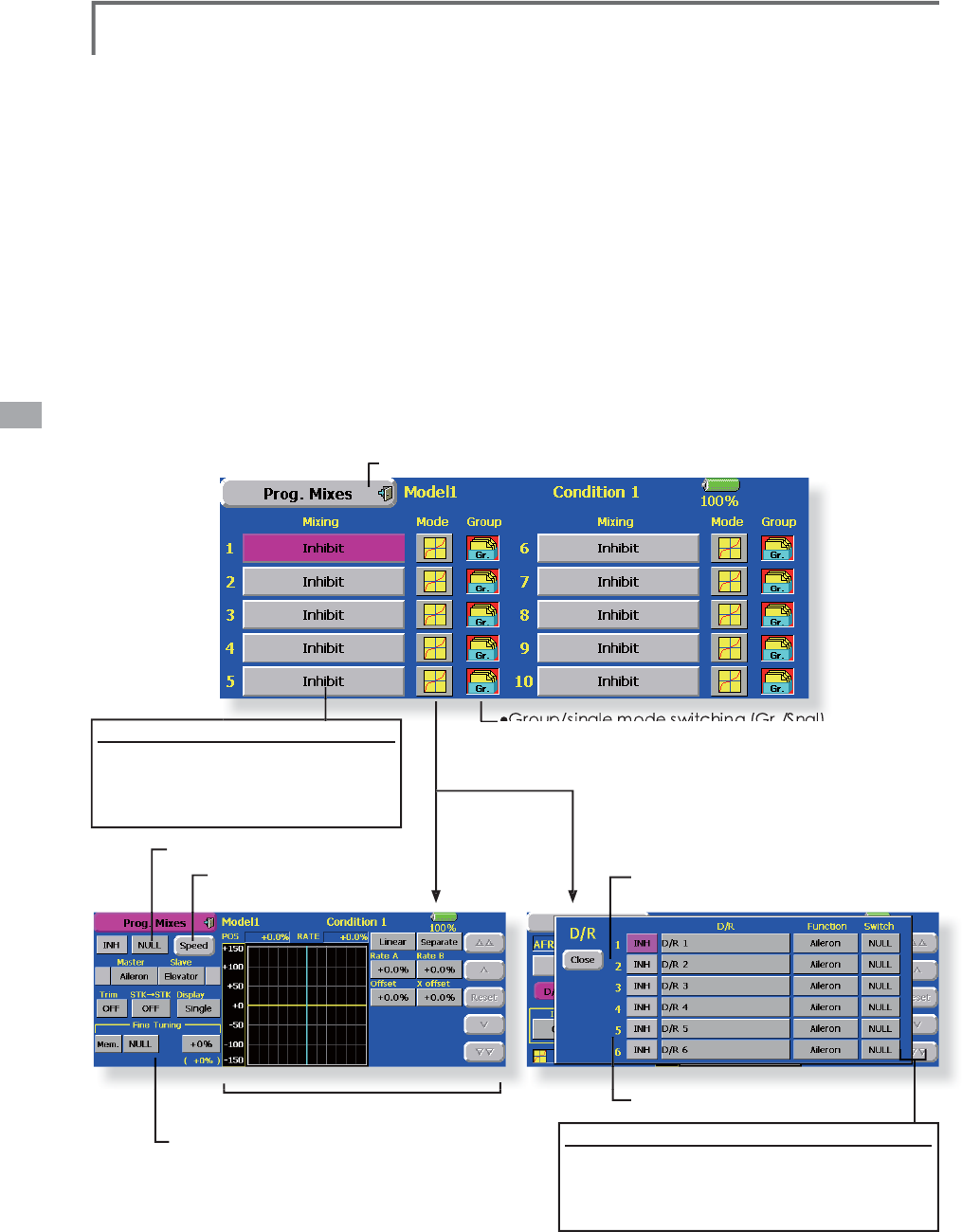
ŏ7RXFKWKH>3UR
J
0L[HV@EXWWRQLQWKH0RGHO0HQXWR
call the setu
p
screen shown below
.
3URJ0L[HV
3
UR
J
UDPPL[LQ
J
ZKLFKFDQEHIUHHO\FXVWRPL]HG8SWRPL[LQ
J
VFDQEHXVHGIR
U
H
DFKFRQGLWLRQ
>
$OOPRGHOW
\S
HV
@
P
rogramma
bl
e m
i
x
i
ng may
b
e use
d
to correc
t
u
ndesired tendencies of the aircraft, and it ma
y
also b
e
X
VHGIRUXQXVXDOFRQWUROFRQ¿JXUDWLRQV0L[LQJPHDQV
th
at t
h
e mot
i
on of a comman
d
c
h
anne
l,
ca
ll
e
d
t
h
e
"master," is added to the motion of the mixed channel,
c
all
ed
"
s
la
ve."
You ma
y
choose to have the Masters trim adde
d
t
o the Slave channel response, if you desire ("Trim"
sett
i
ng
)
. T
h
e m
i
x
i
ng curve can
b
e c
h
ange
d
so t
h
at t
h
e
u
ndesired tendencies can be corrected effectivel
y
b
y
setting the LINEAR1/LINEAR2/EXP1/EXP2/VTR
/
LINE
/
SPLINE mo
d
es. T
h
e De
l
ay funct
i
on can
b
e
pro
g
rammed for each rate. The Dela
y
is used to chan
g
e
t
he rate smoothly when switching. You may define
M
i
x
i
ng ON
/
OFF sw
i
tc
h
, contro
l
or you may c
h
oose to
h
ave mixing remaining on all the time
.
Offset-t
y
pe mixin
g
applies a fixed offset or preset
to t
h
e programme
d
c
h
anne
l
servo operat
i
on an
d
ma
y
c
ontro
l
up to four c
i
rcu
i
ts s
i
mu
l
taneous
ly
.
T
h
e Programma
bl
e m
i
x
i
ng
i
nc
l
u
d
es a powerfu
l
li
n
k
function, which allows Pro
g
rammable mixin
g
to b
e
linked with the special mixing functions, or with other
programma
bl
e m
i
x
i
ng funct
i
ons. T
h
e
li
n
k
funct
i
on ca
n
b
e set up for Master and Slave channel individuall
y
.
T
h
e s
l
ave c
h
anne
l
AFR mo
d
e
(
STK-STK mo
d
e
)
ma
y
be selected, where the slave channel AFR an
d
D
/R settings are observed when Link function is set.
7
K
H
N
QR
E
IRU
¿
QHWXQ
L
QJFDQ
E
HVHWXSIRUHYHU\P
L
[
L
Q
J
c
ircuit. (Fine tune function)
0
L
[
L
Q
J
EXWWRQV
After t
hi
s funct
i
on was act
i
vate
d,
t
h
e
master and slave function names (or
o
ffset mixing) are displayed.
ŏ0L[LQ
J
PRGHFKDQ
J
HEXWWRQ
ŏ*URXSVLQJOH
PRGH
VZLWFKLQJ
*U
6QJO
(For more information, see the descri
p
tion at the back of this manual.)
ŏ2SHUDWLRQFXUYHVHWWLQ
J
ŏ6HUYRVSHHGVHWWLQ
J
ŏ6Z
L
WFKVHOHFW
L
RQ
ŏ)
L
QHWXQ
L
QJWU
L
PVHWW
L
Q
J
(
Timer mode
)
(
Normal mode
)
7
L
P
H
UP
RGH
T
h
e on t
i
me
(
start
/
stop t
i
me
)
can
b
e set up to
9
seconds. It is useful for landin
g
g
ear control of
t
he jet or scale plane, etc.
(
Offset-type mixin
g)
&XUYHW\SH
mixin
g)

107
<Model Menu (Common Functions)>
6HWWLQJPHWKRGV
ŏ*URXSVLQJOHPRGHVHOHFWLRQ
$FWLYDWLQJIXQFWLRQVIRURQO\WKHVHOHFWHG
conditions:
7RXFKWKH*URXSEXWWRQDQGVZLWFKWRWKH
6QJOPRGH
*Each time the button is touched, it toggles between the Gr.
and Sngl modes.
ŏ0L[LQJPRGHVHOHFWLRQ
Using the offset mode:
1. Touch the Mode button and switch to the
Offset mode.
*Each time the button is touched, it toggles between the Mix
and Offset modes.
ŏ0L[LQJVHWXSVFUHHQVHOHFWLRQ
1. Touch the button of the mixing you want
to set. The mixing setup screen is displayed.
$FWLYDWHWKHIXQFWLRQ
$FWLYDWHWKHIXQFWLRQE\WRXFKLQJWKH>,1+@
button.
*Each time this button is touched, it toggles between [INH]
and [ON/OFF].
ŏ0L[LQJ212))VZLWFKVHWWLQJDQG212))
direction switching
*An ON/OFF switch is not set even when the function is
activated.
:KHQ\RXZDQWWRWXUQPL[LQJ212))E\
VZLWFKWRXFKWKH>18//@EXWWRQWRFDOOWKH
6ZLWFK!VFUHHQDQGWKHQVHOHFWWKHVZLWFK
and its ON direction.
*For a description of the selection method, see [Switch
Setting Method] at the back of this manual.
ŏ0DVWHUFKDQQHOVHWWLQJH[FHSWRIIVHWW\SH
mixing)
1. Touch the Master button to call the Function
menu and select the master channel.
7ROLQNWKLVPL[LQJZLWKRWKHUPL[LQJWRXFKWKH
button at the left of the master channel and
VHOHFWOLQN
*Each time the button is touched, it toggles between mixing
direction + and - and "No display" (no link).
*Master channel control can be set to stick, VR, and other
simple travels which do not include ATV, AFR, D/R, mixing
setting, etc. In this case, display the <Switch> screen by
touching the [H/W] button and then select master channel
side control.
ŏ6ODYHFKDQQHOVHWWLQJ
7RXFKWKH6ODYHEXWWRQWRFDOOWKH)XQFWLRQ
menu and select the slave channel.
7ROLQNWKLVPL[LQJZLWKRWKHUPL[LQJWRXFK
the button at the right-hand side of the slave
FKDQQHODQGVHOHFWOLQN
*Each time the button is pressed, it toggles between mixing
direction + and - and "No display" (no link).
ŏ7ULPPRGH212))VHWWLQJ
7RWXUQWKHWULPPRGH212))WRXFKWKH7ULP
button on the screen.
*When mixing includes master side trim, set the Trim button
to [ON]. When mixing does not include master side trim, set
the Trim button to [OFF].
*Each time this button is pressed, it toggles between [ON]
and [OFF].
*This is effective when the master channel is set by Function.
ŏ6ODYHFKDQQHO$)5PRGH67.ń67.
:KHQ/LQNLVVHWDWWKHVODYHVLGHDQG\RX
ZDQWWRDGG$)5'5WRWKHPL[LQJUDWH
VHOHFW>21@:KHQ\RXGRQRWZDQWWRDGG
$)5'5WRWKHPL[LQJUDWHVHOHFW>2))@
*Each time this button is pressed, it toggles between [ON]
and [OFF].
*This is effective when making corrections when the fuselage
is the same but the rudder angles are substantially different.
ŏ0L[LQJFXUYHW\SHVHOHFWLRQ
1. Touch the curve type selection button of the
curve type you want to use to display the
selection screen and then select the curve
you want to use.
*For a description of the curve setting method, see the
description at the back of this manual.
ŏ)LQHWXQLQJWULPVHWWLQJ
:KHQXVLQJWKHFXUYHILQHWXQLQJIXQFWLRQ
WRXFKWKH>18//@EXWWRQRIWKH)LQH7XQLQJ
LWHPWRFDOOWKH6ZLWFK!VFUHHQDQGWKHQ
VHOHFWWKHOHYHU95HWF\RXZDQWWRXVH
)RUDGHVFULSWLRQRIWKH¿QHWXQLQJWULPVHWWLQJPHWKRGVHH
the description at the back of this manual.
ŏ6HUYRVSHHGVHWWLQJ
:KHQVHWWLQJWKHVHUYRVSHHGWRXFKWKH
6SHHGEXWWRQ7KH6HUYR6SHHGVHWXSVFUHHQ
is displayed.
*For a description of the servo speed setting method, see the
description at the back of this manual.
*Offset mixing changes the speed. Use the Speed In and
Speed Out buttons to readjust the speed..
The mixing switch can set a delay with a different rate at
starting and stopping.
*This function is inactive when a mixing switch is not set.
ŏ7KHSURJUDPPDEOHPL[LQJLQPL[LQJPRGH
67.WR67.PL[LQJIXQFWLRQFDQEHXVHGHYHQ
ZKHQWKH0DVWHULVDVWLFNRURWKHUKDUGZDUH
108 <Model Menu (Common Functions)>
6
HWW
L
Q
J
PHWKR
G
&
750PRGH Max
i
mum amount of c
h
an
g
e
near center b
y
center trim operation. When the
adjustment range (Range) value is made small, trim
i
s act
i
ve on
ly
near t
h
e center.
12
50PRGH Norma
l
tr
i
m
(
para
ll
e
l
movement
t
r
i
m
)
operat
i
on. W
h
en t
h
e a
dj
ustment ran
g
e
(
Ran
g
e
)
v
alue is made small, trim is active onl
y
near the
center. Nee
dl
e
hi
g
h
tr
i
m wor
k
s as
hi
g
h
tr
i
m
b
ase
d
on t
h
e center. T
hi
s operat
i
on
i
s s
i
m
il
ar to reverse
ATL trim.
$Q
DFFH
O
H
U
D
WL
R
QI
X
Q
F
WL
R
Q
FD
Q
EH
VH
W
7KL
V
f
unction is used when there are s
y
m
p
toms
o
f the mixture bein
g
either too rich o
r
t
oo lean, which would be
g
enerated by
V
XGGHQR
S
HUDWLRQRIWKHWKURWWOHVWLFN
$
QDFFHOHUDWLRQ
$&/5
IXQFWLRQDQG
G
HFHOHUDWLRQ
'&/5
IXQFWLRQZKLFK
t
em
p
oraril
y
increase and decrease the fuel
s
u
pp
l
y
at acceleration and deceleration,
ca
n
be
se
t
.
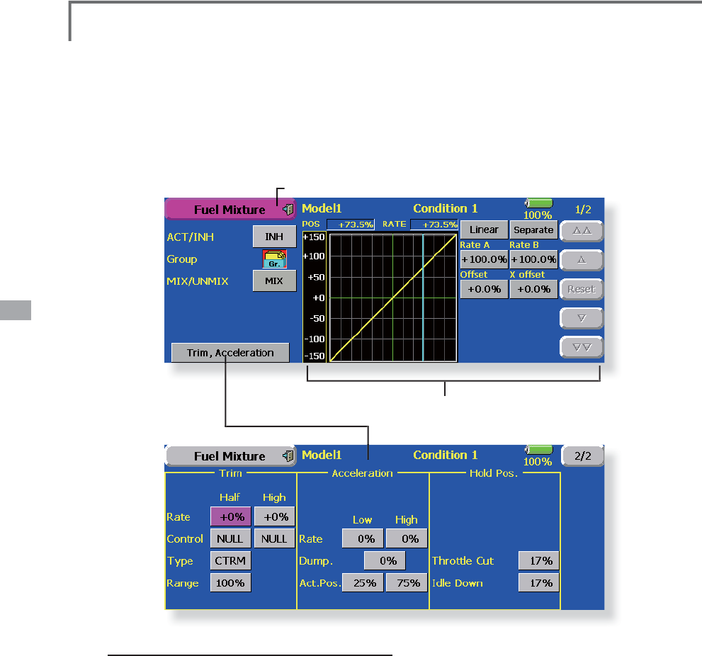
7KHUHWXUQWLPHDIWHURSHUDWLRQ
'XPS
FDQ
E
HVHWIRUERWKVHWWLQ
J
DWDFFHOHUDWLRQ
+L
J
K
a
nd settin
g
at deceleration
(
Low
).
$QHHGOHWKURWWOHFXWIXQFWLRQFDQEHVHW
2
S
HUDWLRQOLQNHGZLWKWKHWKURWWOHKROG
I
XQFWLRQV
&XWDQG,GOH
7KURWWOH&XWIXQFWLRQ
D
QG,GOH'RZQIXQFWLRQLV
S
RVVLEOH
7KHQHHGOHVLGHFXW
S
RVLWLRQFDQEHVHW6HWLW
t
o the fuel side full o
p
en
p
osition
.
:
K
H
QWK
H
MIX
mode is selected
,
the throttle
c
urve set data becomes the mixin
g
master.
I
n th
e
U
NMIX PRGHWKHWKURWWOHVWLFN
S
RVLWLRQ
b
ecomes the mixin
g
master
.
ŏ
5
H
W
X
UQW
R
0
RGH
O0
H
Q
X
ŏ7RXFKWKH
>
)XHO0L[WXUH
@
EXWWRQLQWKH0RGHO0HQXWR
call the setu
p
screen shown below
.
)XHO0L[WXUH 'HGLFDWHGPL[LQ
J
XVHGLQQHHGOHDG
M
XVWPHQWRIHQ
J
LQHVZKLFKXVHDIXHOPL[WXUH
FRQWUROFDUEXUHWRU
>
$LU
S
ODQHKHOLFR
S
WHU
@
This function is dedicated mixin
g
used in needle
adj
ustment of an eng
i
ne t
h
at uses a fue
l
m
i
xture
c
ontro
l
car
b
uretor.
*
T
h
e nee
dl
e c
h
anne
l
i
s ass
i
gne
d
to CH9 as a
d
efau
l
t.
ŏ2SHUDWLRQFXUYHVHWWLQ
J
(For a description of the settin
g
method, see the description at the
b
ac
k
of t
hi
s manua
l
.
)
109
<Model Menu (Airplane/Glider Functions)>
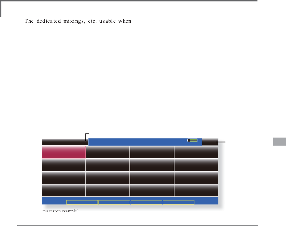
MODEL MENU (AIRPLANE/GLIDER FUNCTIONS)
System Menu Linkage Menu Model Menu Return
Model 1 Condition 1 85%
Model Menu
Condition Select AFR ( D/R ) Prog. Mixes
Flap Setting AIL to CamberFLP
Airbrake to ELE ELE to Camber
RUD to AIL
$,/'LíHUHQWLDO
Servo Monitor
AIL to RUD
CamberFLP to ELE
Camber Mix
1/2
AIL to Brake FLP
RUD to ELE Snap Roll
a
i
rp
l
ane, g
lid
er, or EP g
lid
er mo
d
e
l
type
i
s
s
e
l
ecte
d
are
di
sp
l
a
y
e
d
i
n t
hi
s Mo
d
e
l
Menu
functions section. First use the Model T
y
pe
funct
i
on of t
h
e L
i
n
k
age Menu to preset t
h
e mo
d
e
l
t
y
pe, w
i
n
g
t
y
pe, an
d
ta
il
t
y
pe matc
h
e
d
to t
h
e
fusela
g
e used. Later settin
g
resets the data set b
y
m
i
x
i
ng funct
i
on, etc.
T
hese dedicated mixings can be set for each
f
li
g
h
t con
di
t
i
on, as requ
i
re
d
. W
h
en you want to
use t
h
e s
y
stem
by
sw
i
tc
hi
n
g
t
h
e sett
i
n
g
s for eac
h
condition b
y
switch or stick position, use the
&RQ
GL
W
L
RQ6H
O
HFWIXQFW
L
RQWRD
GG
ÀL
J
K
WFRQ
GL
W
L
RQV
(
Up to 8 con
di
t
i
ons can
b
e use
d)
Note: The T18MZ
i
s des
i
gned so that the a
i
rplane
and gl
i
der
(i
nclud
i
ng EP gl
i
der
)
model types can
handle fuselages of the same wing type.
The functions common to airplanes and gliders,
exce
p
t some dedicated functions, are summarized
without re
g
ard to the model type.
The settin
g
items are different, dependin
g
on the
number o
f
servos, etc. accord
i
n
g
to the w
i
n
g
type
used. However, reread them. The setup screens
i
n
the
i
nstruct
i
on manual are typ
i
cal examples.
ŏ5HWXUQWR+RPHVFUHH
Q
ŏ7RXFKWKH0RGHO0HQXEXWWRQR
I
WKH+RPHVFUHHQWR
call th
i
s Model Menu
.
ŏ:KHQWKHEXWWRQR
I
WKH
I
XQFW
L
RQ\RXZDQWWRVHW
L
V
touc
h
e
d
, a setup screen appears
.
(Model Menu screen example)
*
T
h
e Mo
d
e
l
Menu screen
d
epen
d
s on t
h
e mo
d
e
l
t
y
pe. T
hi
s screen
i
s for mo
d
e
l
t
y
pe A
i
rp
l
ane W
i
n
g
T
y
pe 4AIL+4FLP.
ŏ
7RQH[WSD
JH
Mode
l M
e
n
u
fu
n
c
t
io
n
s
l
is
t
Ɣ
$,/'LIIHUHQWLDO
This function ad
j
usts the left and ri
g
ht ailerons.
5ROOD[LVFRUUHFWLRQDQG¿QHWXQLQJZLWKD95DUH
a
l
so poss
ibl
e. T
hi
s
i
s conven
i
ent w
h
en ma
ki
ng
VHWWLQ
J
VGXULQ
J
ÀL
J
KW
[A
i
rp
l
ane
/
g
lid
er, 2 a
il
erons or more]
Ɣ
)ODS
6
HWW
L
Q
J
7KHÀDSVFDQEHDG
M
XVWHGLQGHSHQGHQWO
\
)RUD
ÀD
S
VPRGHOWKHFDPEHUÀD
S
VFDQEHPL[HGZLWK
WK
H
E
UD
N
H
À
DSV>$
L
US
O
DQH
J
OLG
HU
À
DSVRUPRUH@
Ɣ
$,/WR
&
DPEHU)/3
T
hi
s m
i
x
i
n
g
operates t
h
e cam
b
er f
l
aps
i
n
t
he aileron mode. It im
p
roves the o
p
eration
ch
aracter
i
st
i
c of t
h
e ro
ll
ax
i
s. [A
i
rp
l
ane
/
g
lid
er, 2
DLO
HURQV
À
DSVRUPRUH
@
Ɣ$,/WR%UDNH)/
3
This mixin
g
operates the brake flaps in
t
h
e a
il
eron mo
d
e. It
i
mproves t
h
e operat
i
on
c
haracteristic of the roll axis. [Airplane/
g
lider, 4
À
DSVRUPRUH
@
Ɣ$,/WR58
'
Thi
s m
i
x
i
ng
i
s use
d
w
h
en you want to operate
the rudder at aileron operation. Bankin
g
at a
s
hallow bank angle is possible. [Airplane/glider, 2
D
LO
HURQV
À
DSVRUPRUH@
Ɣ$LUEUDNHWR(/(
T
his mixin
g
is used to correct operation of
the airbrakes (spoilers) when landing. [Airplane/
glid
er, genera
l
]
Ɣ58'WR$,
/
T
hi
s m
i
x
i
n
g
i
s use
d
to correct ro
ll
maneuvers,
knife ed
g
e, etc. of stunt planes. [Airplane/
g
lider,
g
enera
l
]
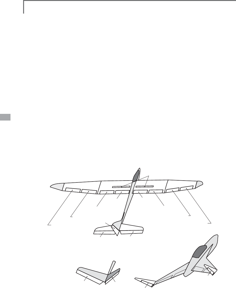
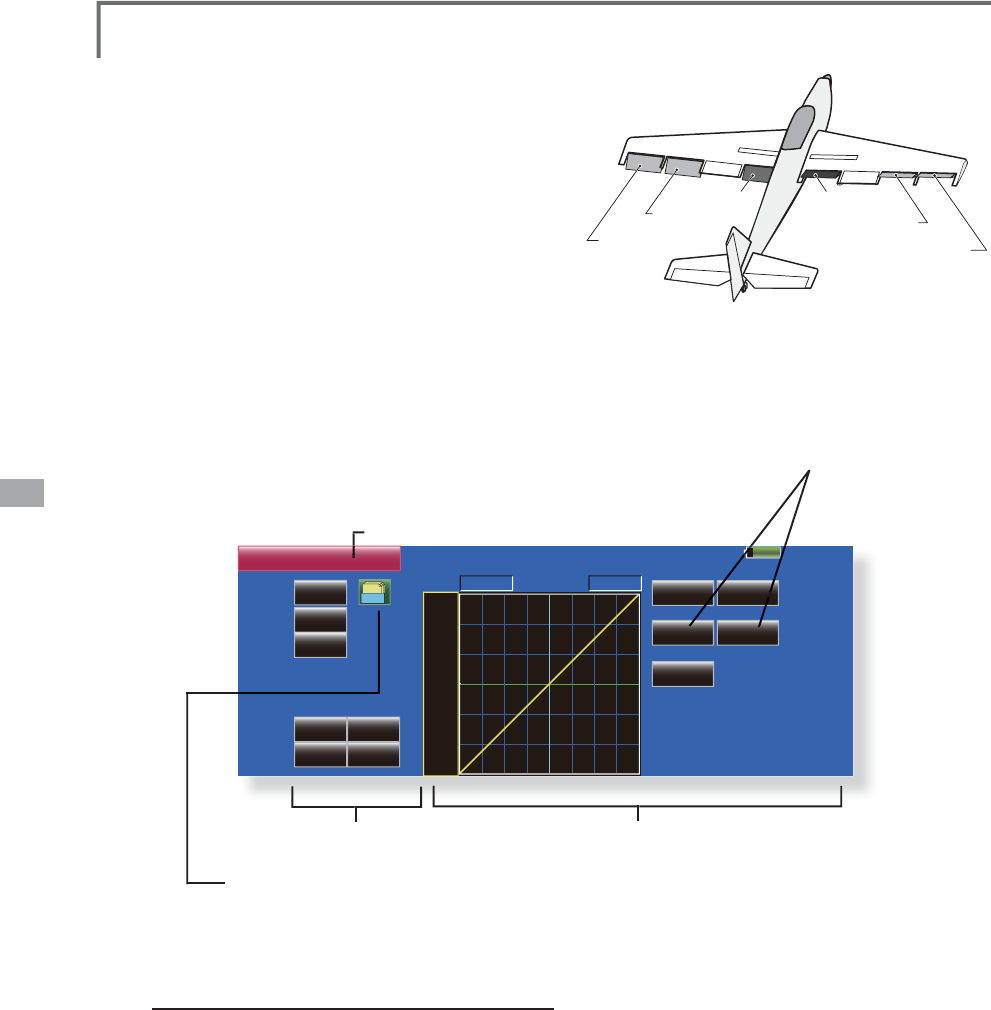
110 <Model Menu (Airplane/Glider Functions)>
AIR BRAKE
AIL 3
(Chip Aileron)
AIL 4
(Chip Aileron)
AIL1
(Main Aileron) AIL 2
(Main Aileron)
FLP 2
(Camber Flap)
FLP 1
(Camber Flap)
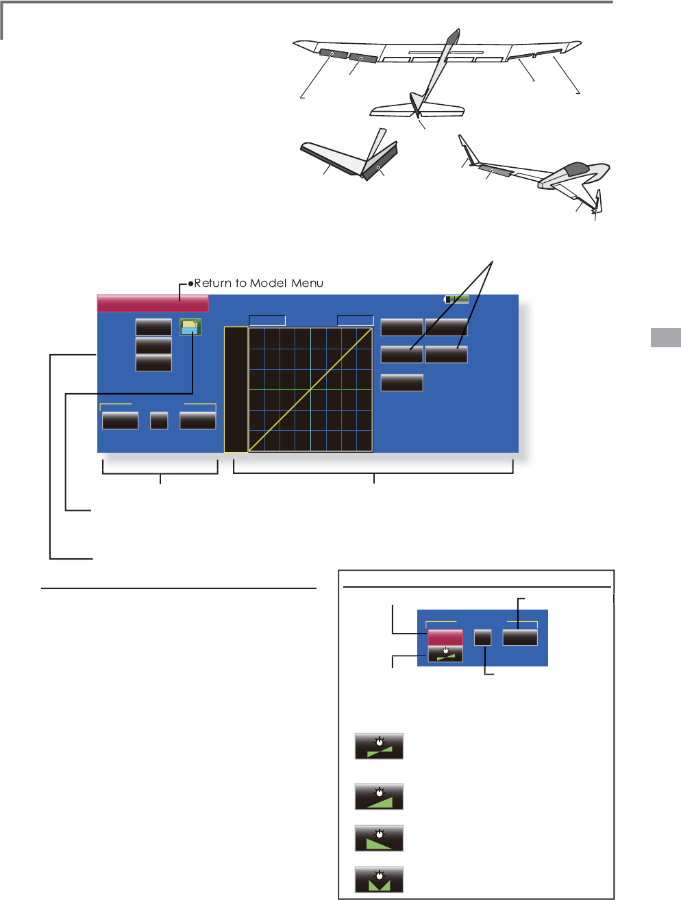
V-TAIL
at AILEVATOR
FLP 3
(Brake Flap)
FLP 4
(Brake Flap)
RUDDER 2
Winglet
RUDDER 1
(ELEVATOR 2)
RUDDER
RUDDER
ELEVATOR
(RUDDER 2)
Winglet
at Flying wing
at Flying wing
at Flying wing
( )
( )
ELEVATOR
(AILERON 5)
ELEVATOR 2
(AILERON 6)
Ɣ&DPEHU0L[
This mixing adjusts the camber and corrects the
elevators. [Airplane/glider, 2 ailerons or more]
Ɣ(/(WR&DPEHU
This mixing is used when you want to the mix
FDPEHUÁDSVZLWKHOHYDWRURSHUDWLRQ/LIWLQJIRUFH
can be increased at elevators up. [Airplane/glider,
2 ailerons or more]
Ɣ&DPEHU)/3WR(/(
This mixing is used to correct for attitude changes
ZKHQWKHFDPEHUÁDSVDUHEHLQJXVHG>$LUSODQH
JOLGHUDLOHURQVÁDSRUPRUH@
Ɣ%XWWHUÀ\&URZ
This function is used when powerful brake operation
is necessary. [Glider, 2 ailerons or more]
Ɣ7ULP0L[
7KHDLOHURQVHOHYDWRUVDQGÁDSVWULPRIIVHWUDWHFDQ
be called by switch or condition selection. [Glider, 2
ailerons or more]
Ɣ$LUEUDNH
This function is used when airbrakes are necessary
ZKHQODQGLQJRUZKHQGLYLQJHWFGXULQJÁLJKW
(Airplane, general)
Ɣ*\UR
This is dedicated mixing when a GYA Series gyro is
used. [Airplane/glider, general]
Ɣ9WDLO
This function adjusts the elevators and rudder of
9WDLOPRGHOV>$LUSODQHJOLGHU9WDLOVSHFLÀFDWLRQV@
Ɣ$LOHYDWRU
This function adjusts the elevators and ailerons of
PRGHOVZLWKHOHYDWRUVSHFLÀFDWLRQV>$LUSODQH
JOLGHUHOHYDWRUVSHFLÀFDWLRQV@
Ɣ:LQJOHW
This function adjusts the left and right rudders
of winglet models. [Airplane/glider, winglet
VSHFLÀFDWLRQV@
Ɣ0RWRU
The operation speed when the motor of F5B and
other EP gliders is started by switch can be set. [EP
glider, general]
Ɣ58'WR(/(
This function is used to correct roll maneuvers, knife
edge, etc. of stunt planes. [Airplane, general]
Ɣ6QDSUROO
This function selects the snap roll switch and adjusts
the steering angle of each rudder. Servo speed can
also be adjusted. [Airplane general]
Ɣ0XOWL(QJLQH
This function adjusts the throttles independently
when using a multi engine model. (Maximum 4
engines) [Airplane, general]
111
<Model Menu (Airplane/Glider Functions)>
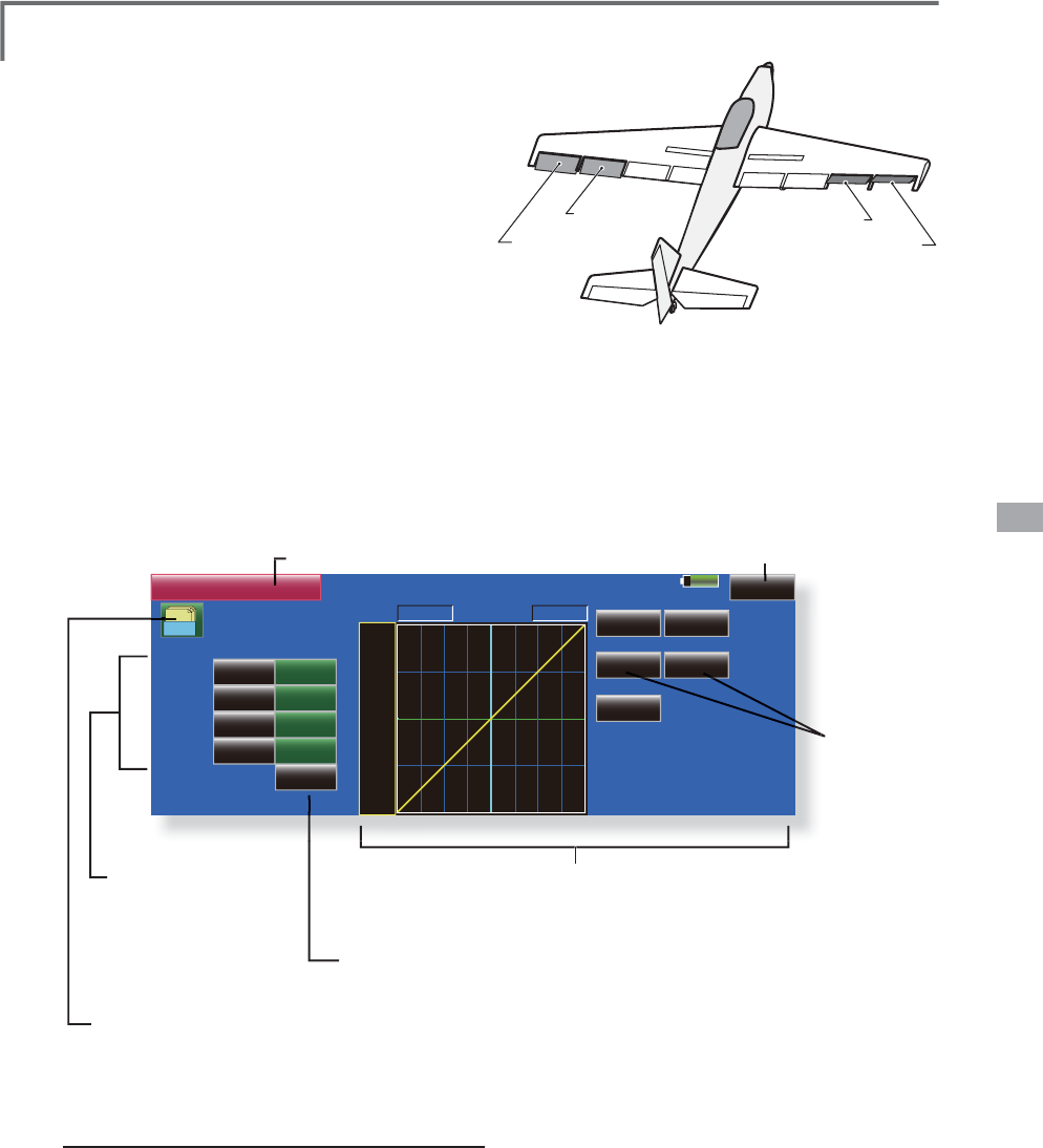
AIL 3
(Chip Aileron) AIL 4
(Chip Aileron)
AIL1
(Main Aileron) AIL 2
(Main Aileron)
85%
$,/'LíHUHQWLDO
100%
/HIW 5LJKW
POS +0.0%
100%
100%
AIL2 100%
100%
AIL3 100%
100%
NULL
AIL4
)LQH7XQLQJ
)LQH7XQLQJ&XUYH
100%
AIL
0DVWHU
/LQHDU 6HSDUDWH
+100.0% +100.0%
0RGHO &RQGLWLRQ
*U +100
+50
+0
5$7(
5DWH$
+0.0%
2íVHW
5DWH%
+0.0%
ŏ5
H
W
X
UQW
R
0
RGH
O0
H
Q
X
ŏ7RXFKWKH>$,/'LIIHUHQWLDO@EXWWRQLQWKH0RGHO0HQXWR
ca
ll
t
h
e setup screen s
h
own
b
e
l
ow
.
AIL Differential [Airplane/
g
lider, 2 ailerons or mor
e
T
he left and ri
g
ht ailerons differential can be
a
dj
uste
d
i
n
d
epen
d
ent
l
y. T
h
e
di
fferent
i
a
l
rate can
a
l
so
b
e a
dj
uste
d
accor
di
n
g
to t
h
e f
lyi
n
g
state
by
V
HWWLQ
J
D¿QHWXQLQ
J
95
ŏ$ÀQHWXQLQJFXUYHFDQEHVHW
N
ote: Aileron up/down settin
g
(%)
reset is +100
%
when reset when settin
g
is +, and -100
%
when reset
ZKHQVHWW
L
QJ
L
V/H
I
WDQGU
L
JKWP
L
[
L
QJFDXVHVDQG
WRFKDQJH%H
I
RUH
Á
\
L
QJFRQ
À
UPWKHG
L
UHFW
L
RQR
I
o
p
eration.
ŏ&DOOVWKH$)5VFUHHQG
L
UHFWO\
when ad
j
ust
i
ng a
i
leron
RSHUDW
L
RQ$)5
ŏ)LQHWXQLQJ95VHWWLQ
J
7KHJUDSKLVRSHUDWHGE\VHWWLQJD95HWF
ŏ*URXSV
L
QJOHPRGHVZ
L
WFK
L
QJ
*U6QJO
(
For more
i
nformat
i
on, refer to t
h
e
d
escr
i
pt
i
on at t
h
e
b
ac
k
of t
hi
s manua
l
.
)
ŏ
$
L
OHURQOH
I
WU
L
JKW
a
d
j
ustmen
t
:LQJW\SHDLOHURQVVFUHHQ
!
*
T
h
e
di
sp
l
a
y
screen
i
s an examp
l
e. T
h
e actua
l
screen
d
epen
d
s on t
h
e
Mo
d
e
l
T
y
pe.
ŏ
2
YHUD
OO
a
d
j
ustmen
t
E\
5DWH$
D
Q
G
5
D
W
H
%
*The displa
y
is reversed b
y
m
i
x
i
n
g
w
i
t
h
a
il
eron operat
i
o
n
ŏ
)LQHWXQLQJFXUYHVHWWLQJ
(For a description of the setting
m
ethod, see the descri
p
tion at the
e
nd the manual.
)
6
HWW
L
Q
J
PHWKRG
ŏ7RXFKWKHDLOHURQ$,/aOHIWRUULJKWEXWWRQ
and adjust the aileron angles when the stick is
moved to the left (or right) end.
*The aileron AFR screen can be directly called from the AIL
Differential setu
p
screen. ([Master] button)
ŏ:KHQVHWWLQJWKHÀQHWXQLQJ95WRXFKWKH18//
button to call the <Switch> screen, and then
VHOHFWWKHÀQHWXQLQ
J
95
ŏ7KH
À
QHWXQ
L
Q
J
UDWHFDQEHVHWE\FXUYH
X
112 <Model Menu (Airplane/Glider Functions)>
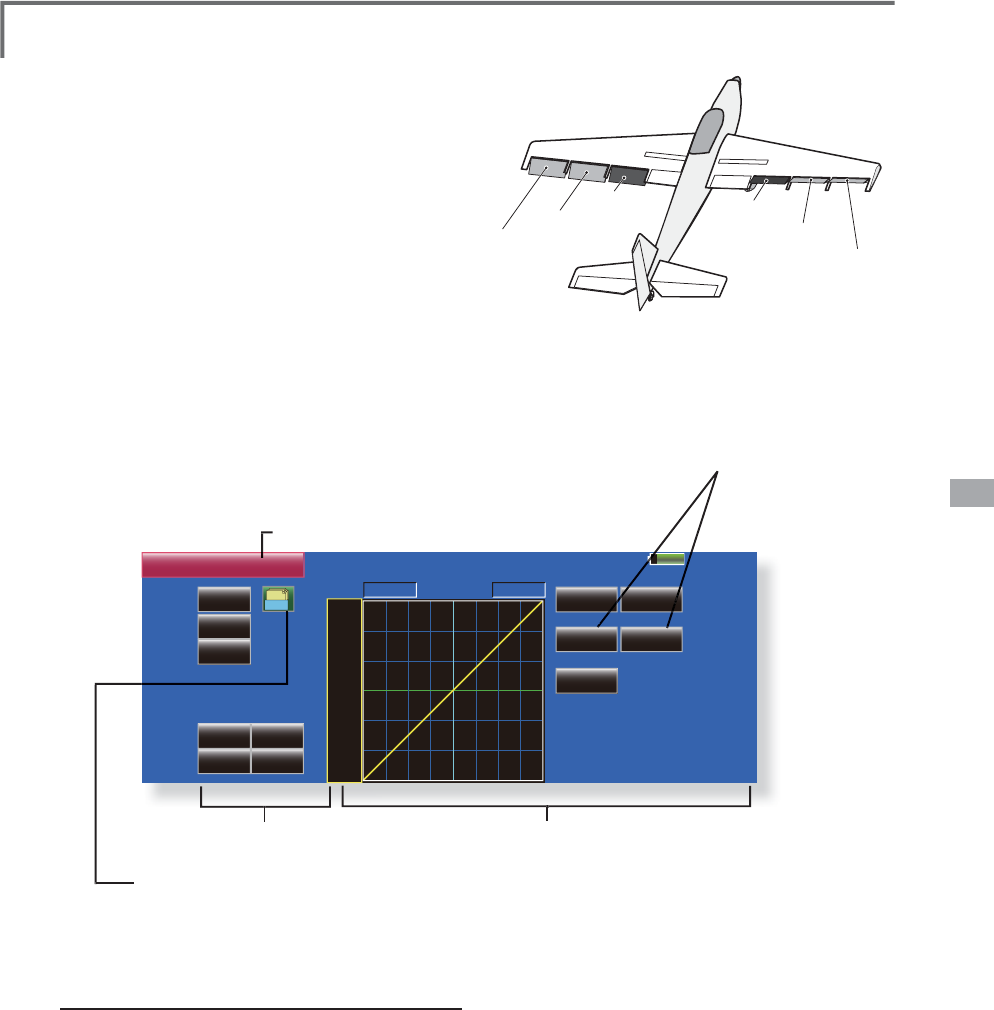
FLP 2
(Camber Flap)
FLP 1
(Camber Flap)
FLP 3
(Brake Flap) FLP 4
(Brake Flap)
85%
Flap Setting Model 1 Condition 1
Group
FLP FLP2
+100%
+100%
Down +100%
+0%
2íVHW +0%
UP +100%
Camber Flap
Group
FLP3 FLP4
+100%
+100%
Down +100%
+0%
2íVHW +0%
UP +100%
+100%
Down
+0%
2íVHW
UP +100%
Group
OFF
Switch
ACT INH
Brake Flap B.Flap to C.Flap
Gr.
Gr. Gr.
ŏ
5
H
W
X
UQW
R
0
RGH
O0
H
Q
X
ŏ
7RXFKWKH>)ODS6HWWLQ
J
@EXWWRQLQWKH0RGHO0HQXWR
c
all the setu
p
screen shown below
.
)ODS6HWWLQJ >&RUUHVSRQGLQ
J
PRGHOW\SH@$LUSODQH
J
OLGHUÁDSVRUPRU
H
7KHX
S
GRZQWUDYHORIHDFKÀD
S
FDPEHUÀD
S
V
)/3
E
UD
N
HI
O
DSV)/3
FDQ
E
HD
GM
XVWH
G
i
n
d
epen
d
ent
ly
at eac
h
servo accor
di
n
g
to t
h
e w
i
n
g
ty
pe.
ŏ
7KHR
S
HUDWLRQUHIHUHQFH
S
RLQWRIHDFKÁD
S
FDQEH
o
ffset
T
h
e cam
b
er f
l
aps of a 4-f
l
ap mo
d
e
l
can
b
e
P
L[HGZLWKWKHEUDNHÀDSV%UDNH)/3WRFDPEHU
FLP
)
ŏ
$Q21
2))VZLWFKFDQEHVHW
ŏ
*URXSVLQJOHPRGHVZLWFKLQJ
(
Gr./Sngl
)
(For more information, see the descri
p
tion
a
t the back of this manual.
)
:LQJW\SHÀDSVVFUHHQ
!
*
T
h
e
di
sp
l
a
y
screen
i
s an examp
l
e. T
h
e actua
l
screen
d
epen
d
s on t
h
e
mo
d
e
l
t
y
pe.
6HWWLQJPHWKR
G
ŏ
7RXFKWKH
Á
DS
)/3
a8SRU'RZQEXWWRQ
a
ccord
i
n
g
to the w
i
n
g
type and ad
j
ust the travel
i
ndependently.
ŏ
7RR
II
VHWWKHR
S
HUDW
L
RQUH
I
HUHQFH
S
R
L
QWR
I
HDFK
ÁDSWRXFKWKHFRUUHVSRQGLQJ2IIVHWEXWWRQ8VH
t
he adjustment buttons displayed on the screen to
o
ffset the reference
p
oint.
ŏ
:KHQXVLQ
J
%UDNH)/3WR&DPEHU)/3PL[LQ
J
WRXFK
W
KH$&7EXWWRQDQGVHWWKHIXQFWLRQWR$&7
21
:KHQVHWW
L
Q
J
DVZ
L
WFKWRXFKWKH>18//@EXWWRQR
I
t
he sw
i
tch to call the <Sw
i
tch> screen
,
and then
VHOHFWWKHVZ
L
WFKDQGVHW
L
WV21G
L
UHFW
L
RQ
$OZD\V
21DW18//VHWW
L
QJ
(
For a description of the switch selection method,
see the description at the back of this manual.)
ŏ
2
SHUD
WL
RQUH
I
HUHQFHSR
L
Q
W
R
II
VH
W
ŏ8SV
L
GH'RZQV
L
GHDG
M
XVWPHQW
113
<Model Menu (Airplane/Glider Functions)>
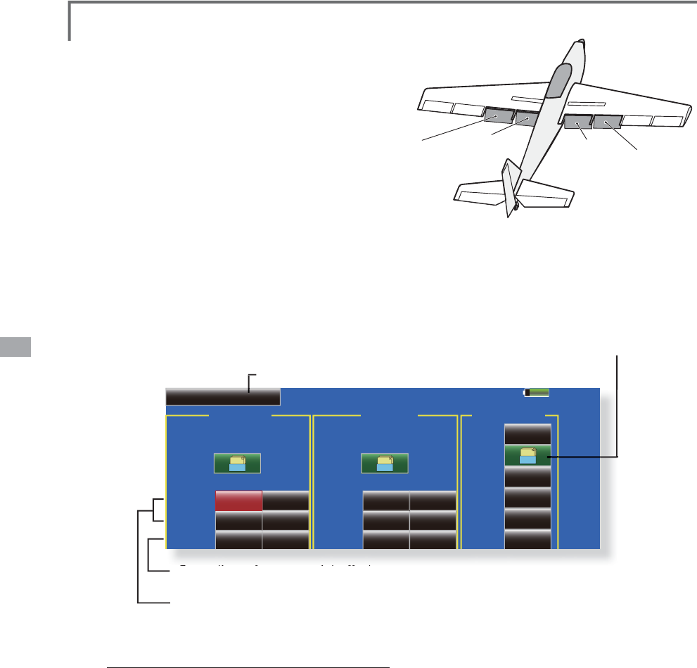
AIL 3
(Chip Aileron) AIL 4
(Chip Aileron)
AIL1
(Main Aileron) AIL 2
(Main Aileron)
FLP 2
(Camber Flap)
FLP 1
(Camber Flap)
85%
AIL to CamberFLP
INH POS +0.0%
Switch
Link
ACT
Left Right
Linear Separate
+100.0% +100.0%
Model 1 Condition 1
Gr. +150
+100
+50
+0
-50
-150
-100
RATE
Rate A
+0.0%
2íVHW
Rate B
+0.0%
INH
OFF
FLP
FLP2
+0% +0%
+0% +0%
ŏ5
H
W
X
UQW
R
0
RGH
O0
H
Q
X
$,/WR&DPEHU)/3
>
&RUUHVSRQGLQ
J
PRGHOW\SH@$LUSODQH
J
OLGHUDLOHURQVÁDSV
o
r m
o
r
e
7KL
VP
L
[
L
QJRSHUDWHVW
K
HFDP
E
HU
À
DSV
)/3
in the aileron mode. When the aileron stic
k
is mani
p
ulated, the ailerons and camber fla
p
s
p
erform a
il
eron operat
i
on s
i
mu
l
taneous
l
y an
d
the o
p
eration characteristic of the roll axis is
im
p
roved.
ŏ7KHDLOHURQOHIWUL
J
KWPL[LQ
J
UDWHRIHDFKÁDSVHUYR
FDQEHÀQHWXQHG
ŏ$P
L
[
L
Q
J
FXUYHFDQEHVHW
ŏ$Q21
2))VZ
L
WFKFDQEHVHW
ŏ/
L
QN
L
Q
J
L
VSRVV
L
EOH/
L
QNVWK
L
VP
L
[
L
Q
J
WRRWKHUP
L
[
L
Q
J
V
ŏ
7RXFKWKH>$,/WR&DPEHU)/3@EXWWRQ
L
QWKH0RGH
M
enu to ca
ll
t
h
e setup screen s
h
own
b
e
l
ow
.
*
T
h
e
di
sp
l
a
y
screen
i
s an examp
l
e. T
h
e actua
l
screen
d
epen
d
s on t
h
e
m
o
d
e
l
type.
ŏ0
L
[
L
QJFXUYHVHWW
L
Q
J
(
For a
d
escr
i
pt
i
on of t
h
e curve sett
i
n
g
met
h
o
d
, see t
h
e
d
escr
i
pt
i
on at t
h
e
b
ac
k
of t
hi
s manua
l
.
)
ŏ$G
M
XVWPHQWRIHDFKÁDS
se
rv
o
ŏ*URXSVLQ
J
OHPRGHVHWWLQ
J
*U6Q
J
O
(For more information, see the descri
p
tion at the back
of this manual.
)
ŏ/HIWULJKWRYHUDOO
adjustment at
5
D
W
H
$
D
Q
G
5
D
W
H
%
6
HWWLQ
J
PHWKRG
ŏ7RXFKWKH$&7EXWWRQDQGVHWWKHIXQFWLRQWR$&7
21
ŏ:KHQVHWWLQ
J
DVZLWFKWRXFKWKH>18//@EXWWRQRI
the switch to call the <Switch> screen, and then
VHOHFWWKHVZ
L
WFKDQGVHW
L
WV21G
L
UHFW
L
RQ
$OZD\V
2
1DW18//VHWW
L
Q
J
(
For a descr
i
pt
i
on o
f
the sw
i
tch select
i
on method,
see the descr
i
pt
i
on at the back o
f
th
i
s manual.
)
ŏ7RXFKWKHOHIWRUULJKWEXWWRQRIHDFKÁDSVHUYR
and adjust the mixing rate with the adjustment
b
uttons.
*When the mixing direction is reversed by the linkage,
ad
j
ustments can be made b
y
chan
g
in
g
the mixin
g
rate
p
olarit
y
.
ŏ$P
L
[
L
Q
J
FXUYHFDQEHVHW
(
For a descr
i
pt
i
on o
f
the m
i
x
i
ng curve sett
i
ng
method, see the descr
ip
t
i
on at the back o
f
th
i
s
manual.)
ŏ7RVHWOLQNLQJWRXFKWKH/LQNEXWWRQDQGVHWLWWR
2
1
A
114 <Model Menu (Airplane/Glider Functions)>
AIL 3
(Chip Aileron) AIL 4
(Chip Aileron)
AIL1
(Main Aileron) AIL 2
(Main Aileron)
FLP 3
(Brake Flap) FLP 4
(Brake Flap)
85%
AIL to Brake FLP
INH POS +0.0%
Switch
Link
ACT
Left Right
Linear Separate
+100.0% +100.0%
Model 1 Condition 1
Gr. +150
+100
+50
+0
-50
-150
-100
RATE
Rate A
+0.0%
2íVHW
Rate B
+0.0%
INH
OFF
FLP3
FLP4
+0% +0%
+0% +0%
ŏ
5
H
W
X
UQW
R
0
RGH
O0
H
Q
X
$,/WR%UDNH)/3 >&RUUHVSRQGLQ
J
PRGHOW\SH@$LUSODQH
J
OLGHUÁDSVRUPRUH
7
KL
VP
L
[
L
QJRSHUDWHVW
K
H
E
UD
N
H
À
DSV
)/3
i
n the aileron mode. When the aileron stick
i
s mani
p
ulated, the aileron and brake fla
p
s
perform t
h
e a
il
eron operat
i
on s
i
mu
l
taneous
l
y
a
nd the o
p
eration characteristic of the roll axis is
i
m
p
roved.
ŏ
7KHDLOHURQOHIWDQGUL
J
KWPL[LQ
J
UDWHVFDQEH
D
G
M
XVWHGIRUHDFKÁDSVHUYR
ŏ
$P
L
[
L
Q
J
FXUYHFDQEHVHW
ŏ
0
L
[
L
Q
J
GXU
L
Q
J
ÁLJ
KWFDQEHWXUQHG212))E\
VHWW
L
Q
J
DVW
L
FN
$OZD\V21DW18//VHWW
L
Q
J
ŏ
/
L
QN
L
QJFDQEHVHW/
L
QNVWK
L
VP
L
[
L
QJWRRWKHUP
L
[
L
QJV
ŏ7RXFKWKH>$,/WR%UDNH)/3@EXWWRQ
L
QWKH0RGHO
Menu to ca
ll
t
h
e setup screen s
h
own
b
e
l
ow
.
*
T
h
e
di
sp
l
a
y
screen
i
s an examp
l
e. T
h
e actua
l
screen
d
epen
d
s on t
h
e
mo
d
e
l
type.
ŏ0
L
[
L
QJFXUYHVHWW
L
Q
J
(
For a
d
escr
i
pt
i
on of t
h
e curve sett
i
ng met
h
o
d
, see t
h
e
description at the back of this manual.)
ŏ
$G
M
XVWPHQWRIHDFKÁDS
se
rv
o
ŏ
*URXSVLQ
J
OHPRGHVHWWLQ
J
*U6Q
J
O
(
For more information, see the descri
p
tion at the back
of this manual.
)
ŏ
/HIWULJKWRYHUDOO
a
djustment by
5D
W
H
$
D
Q
G
5
D
W
H
%
Ɣ6HWWLQ
J
PHWKR
G
ŏ
7RXFKWKH$&7EXWWRQDQGVHWWKHIXQFWLRQWR$&7
21
ŏ
:KHQVHWWLQ
J
DVZLWFKWRXFKWKH>18//@EXWWRQRI
t
he switch to call the <Switch> screen, and then
VHOHFWWKHVZ
L
WFKDQGVHW
L
WV21G
L
UHFW
L
RQ
$OZD\V
21DW18//VHWW
L
Q
J
(
For a descr
i
pt
i
on o
f
the sw
i
tch select
i
on method,
see the descr
i
pt
i
on at the back o
f
th
i
s manual.
)
ŏ
7RXFKWKHOHIWRUULJKWEXWWRQRIHDFKÁDSVHUYR
a
nd adjust the mixing rate with the adjustment
b
uttons.
*
When the mixing direction is reversed by the linkage,
a
d
j
ustments can be made b
y
reversin
g
the mixin
g
rate
polarit
y
.
ŏ
$PL[LQ
J
FXUYHFDQEHVHW
(
For a descr
i
pt
i
on o
f
the curve sett
i
n
g
method, see
the descr
i
pt
i
on at the back o
f
th
i
s manual.
)
ŏ
7RVHWO
L
QN
L
QJWRXFKWKH/
L
QNEXWWRQDQGVHW
L
WWR
2
1
A
115
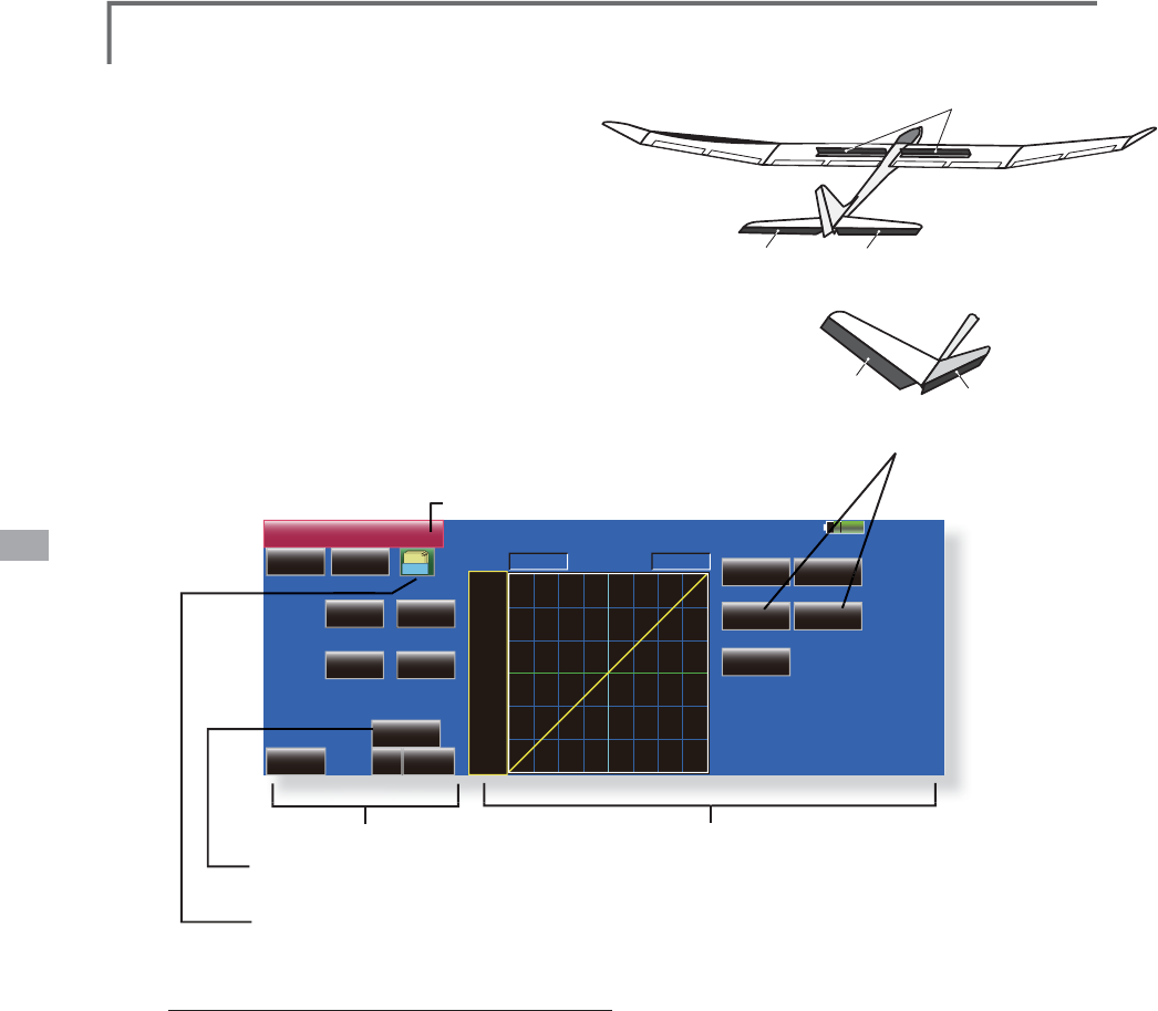
<Model Menu (Airplane/Glider Functions)>
RUDDER 2 RUDDER
RUDDER
at V-TAIL
RUDDER 2
RUDDER 1
at Flying wing
AIL 3
(Chip Aileron)
AIL 4
(Chip Aileron)
AIL1
(Main Aileron)
AIL1
AIL2
AIL 2
(Main Aileron)
85%
AIL to RUD
INH POS +0.0%
Switch
Display
ACT
Fine Tuning
Linear Separate
+100.0% +100.0%
Model 1 Condition 1
Gr. +150
+100
+50
+0
-50
-150
-100
RATE
Rate A
+0.0%
2íVHW
Rate B
+0.0%
Single
OFF
NULL 0%
+
( +0%)
AIL to RUD >&RUUHVSRQGLQ
J
PRGHOW\SH@$LUSODQH
J
OLGHU
J
HQHUD
O
U
se this mixin
g
when
y
ou want to mix the
r
u
dd
ers w
i
t
h
a
il
eron operat
i
on.
ŏ$PL[LQ
J
FXUYHFDQEHVHW
ŏ0
L
[
L
Q
J
GXU
L
Q
J
ÁLJ
KWFDQEHWXUQHG212))E\
V
HWW
L
Q
J
DVZ
L
WFK
$OZD\V21DW18//VHWW
L
Q
J
ŏ7KHP
L
[
L
QJUDWHFDQEH
À
QHWXQHGE\VHWW
L
QJD95
ŏ7RXFKWKH
>
$,/WR58'
@
EXWWRQLQWKH0RGHO
Menu to call the setu
p
screen shown below
.
*The displa
y
screen is an example. The actual screen depends
on t
h
e mo
d
e
l
.
ŏ
0
L
[
L
QJFXUYHVHWW
L
QJ
(
For a
d
escr
i
pt
i
on of t
h
e curve sett
i
n
g
met
h
o
d
, see t
h
e
d
escr
i
pt
i
on at t
h
e
b
ac
k
of t
hi
s manua
l
.
)
ŏ)
L
QHWXQ
L
QJ95VHWW
L
Q
J
ŏ*URXSVLQJOHPRGHVHWWLQJ*U6QJO
(
For more
i
nformat
i
on, see t
h
e
d
escr
i
pt
i
on at t
h
e
b
ack of this manual.
)
ŏ/H
I
WU
L
JKWRYHUDOO
adjustment by
5DWH$DQ
G
5DWH
%
6
HWWLQ
J
PHWKRG
ŏ7RXFKWKH$&7EXWWRQDQGVHWWKHIXQFWLRQWR$&7
21
ŏ:KHQVHWWLQ
J
DVZLWFKWRXFKWKH>18//@EXWWRQRI
the sw
i
tch to call the <Sw
i
tch> screen, and then
VHOHFWWKHVZ
L
WFKDQGVHW
L
WV21G
L
UHFW
L
RQ
$OZD\V
2
1DW18//VHWW
L
QJ
(
For a descr
i
pt
i
on o
f
the sw
i
tch select
i
on method,
see the description at the back of this manual.)
ŏ:KHQVHWWLQJD95WRXFKWKH)LQH7XQLQJ18//
button to call the <Switch> screen, and then
VHOHFWWKH957KHDG
M
XVWPHQWUDWHDQGGLUHFWLRQ
FDQEHVHW7KH95RSHUDWLRQPRGHFDQDOVREH
selected.
ŏ$P
L
[
L
Q
J
FXUYHFDQEHVHW
(
For a descr
i
pt
i
on o
f
the curve sett
i
ng method, see
the descr
i
pt
i
on at the back o
f
th
i
s manual.
)
ŏ7KHFXUYHGLVSOD\PRGHFDQEHFKDQJHG
6LQJOH'LVSOD\VWKHPL[LQJFXUYHRQO
\
)LQHWXQLQJ'LVSOD\VWKHPL[LQJUDWHRIWKHÀQH
WXQLQ
J
9
5
$OO&RQG'LVSOD\VWKHPL[LQ
J
FXUYHRIDOOWKH
FRQG
L
W
L
RQV
:KHQFRQG
L
W
L
RQVDUHVHW
ŏ
&XUYHG
L
VSOD\PRGHVHOHFW
L
RQ(Sin
g
le/Fine tunin
g
/All Cond.)
Fine Tuning
LD 0%
+
( +0%)
)LQHWXQLQ
J
95VHWWLQ
J
0L[LQ
J
UDWH
DWFHQWHURI9
5
:KHQWKH95LVWXUQHGFRXQWHUFORFNZLVH
a
nd clockwise, the mixing rate increases
a
nd decreases, res
p
ectivel
y.
0L[LQJUDWHDWOHIWHQGRI9
5
:KHQWKH95
L
VWXUQHGWKHP
L
[
L
QJUDWH
i
n
c
r
eases.
0L[LQJUDWHDWULJKWHQGRI95
:KHQWKH95
L
VWXUQHGWKHP
L
[
L
QJUDWH
i
ncreases
.
:KHQWKH95LVWXUQHGWRWKHOHIWRUULJKW
of
the neutral pos
i
t
i
on, the m
i
x
i
ng rate
i
n
c
r
eases.
ŏ95VHOHFW
L
RQ
ŏ5DWHDGMXVWPHQW
W
ŏ2
S
HUDWLRQPRGHVHOHFWLR
Q
'
L
VS
O
D\H
G
DW95VHWW
L
QJ
ŏ$GMXVWPHQWGLUHFWLRQ
settin
g
>
2
S
HUDWLRQPRGHV
@
r.
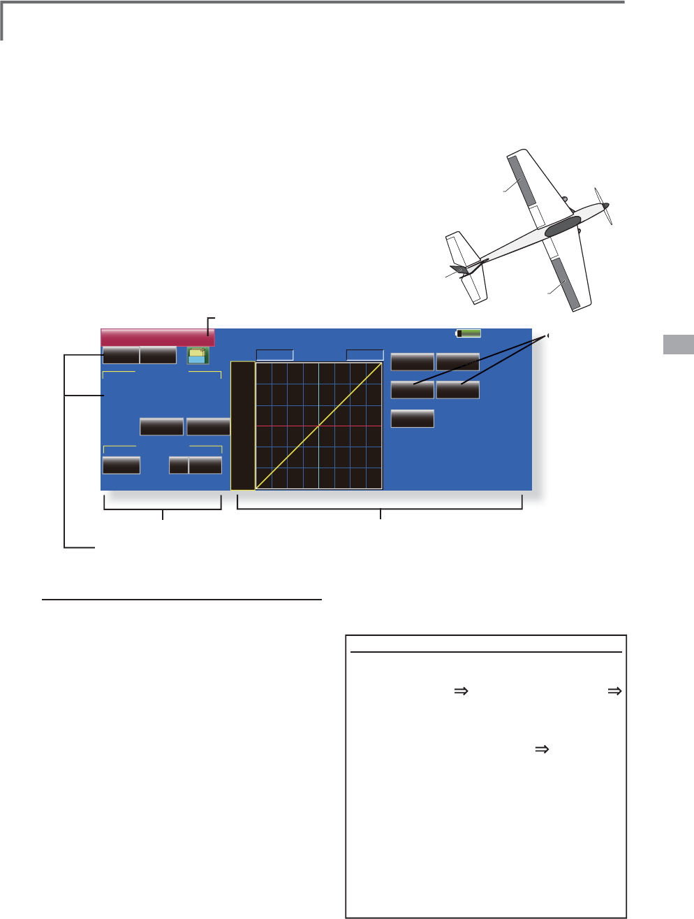
116 <Model Menu (Airplane/Glider Functions)>
AIRBRAKE
ELEVATOR ELEVATOR 2
V-TAIL
ELEVATOR ELEVATOR 2
85%
Airbrake to ELE
INH OFF POS +0.0%
( +0%) ( +0%)
( +0%) ( +0%)
Linear Separate
+100.0% +100.0%
Model 1 Condition 1
Gr.
+150
+100
+50
+0
-50
-150
-100
RATE
Rate A
+0.0%
2íVHW
Rate B
+0.0%
Fine Tuning Single
NULL +0%
Rate 1 Rate 2
ELE
ELE2
+0% +0%
+0% +0%
ŏ
5
H
W
X
UQW
R
0
RGH
O0
H
Q
X
$LUEUDNHWR(/( >&RUUHVSRQGLQ
J
PRGHOW\SH@$LUSODQH
J
OLGHU
J
HQHUD
O
T
his mixin
g
is used when
y
ou want to mix
t
h
e e
l
evators w
i
t
h
a
i
r
b
ra
k
e
(
spo
il
er
)
operat
i
on. It
r
a
i
ses t
h
e e
l
evators to correct for
d
roop
i
n
g
of t
h
e
n
ose durin
g
airbrake operation.
*
This function does not operate when airbrake is not assi
g
ned
at the Function menu in the Linka
g
e Menu.
ŏ7KH5DWHVLGH5DWHVLGHPL[LQ
J
UDWHZLWKWKH
elevator servos can be ad
j
usted.
ŏ$P
L
[
L
Q
J
FXUYHFDQEHVHW
ŏ0
L
[
L
Q
J
GXU
L
Q
J
ÁLJ
KWFDQEHWXUQHG212))E\
V
HWW
L
QJDVZ
L
WFK
$OZD\V21DW18//VHWW
L
QJ
ŏ7KHP
L
[
L
QJUDWHFDQEH
À
QHWXQHGE\VHWW
L
QJD95
ŏ
7RXFKWKH>$
L
UEUDNHWR(/(@EXWWRQ
L
QWKH0RGHO0HQX
t
o ca
ll
t
h
e setup screen s
h
own
b
e
l
ow
.
ŏ
0
L
[
L
QJFXUYHVHWW
L
QJ
(For a description of the curve setting method, see the
descri
p
tion at the back of this manual.)
ŏ
)LQHWXQLQ
J
95VHWWLQ
J
ŏ
&XUYHGLVSOD\PRGHVZLWFKLQ
J
(
S
i
n
gl
e
/
F
i
ne tun
i
n
g/
A
ll
Con
d
.
)
ŏ
/H
I
WU
L
JKWRYHUDOO
a
d
j
ustment by
5
DWH$DQ
G
5DWH%
6HWWLQ
J
PHWKRG
ŏ7RXFKWKH,1+EXWWRQDQGVHWWKHIXQFWLRQWR$&7
21
ŏ:KHQVHWWLQ
J
DVZLWFKWRXFKWKH>18//@EXWWRQ
to call the <Switch> screen, and then select the
VZ
L
WFKDQGVHW
L
WV21G
L
UHFW
L
RQ
$OZD\V21DW
18//VHWW
L
Q
J
(
For a descr
i
pt
i
on o
f
the sw
i
tch select
i
on method,
see the descr
i
pt
i
on at the back o
f
th
i
s manual.
)
ŏ:KHQVHWWLQJD95WRXFKWKH)LQHWXQLQJ18//
button to call the <Switch> screen, and then
VHOHFWWKH957KHDGMXVWPHQWUDWHDQGGLUHFWLRQ
FDQEHVHW7KH95RSHUDWLRQPRGHFDQDOVREH
set.
)RUDGHVFU
L
SW
L
RQR
I
WKH
À
QHWXQ
L
Q
J
95VHWW
L
Q
J
m
ethod, see the descr
i
pt
i
on at the back o
f
th
i
s
m
anual.
)
ŏ$P
L
[
L
QJFXUYHFDQEHVHW
(For a description of the curve setting method,
see the description at the back of this manual.)
ŏ7KHFXUYHGLV
S
OD
\
PRGHFDQEHVHW
ŏ*URXSV
L
QJOHPRGHVZ
L
WFK
*U6QJO
(
For more
i
nformat
i
on, see t
h
e
d
escr
i
pt
i
on at t
h
e
b
ac
k
of t
hi
s manua
l
.
)
R
6
LQ
J
OH'LVSOD\VWKHPL[LQ
J
FXUYHRQO\
)
LQHWXQLQ
J
'LVSOD\VWKHDG
M
XVWPHQWUDWHRIWKH
À
QHWXQ
L
Q
J
95
$
OO&RQG'
L
VSOD\VWKHP
L
[
L
Q
J
FXUYHR
I
DOOWKH
F
RQG
L
W
L
RQV
:KHQFRQG
L
W
L
RQVDUHVHW
Rate
1
117
<Model Menu (Airplane/Glider Functions)>
RUDDER
AIL1
AIL 2
85%
RUD to AIL
INH OFF POS +0.0%
( +0%)
Linear Separate
+100.0% +100.0%
Model 1 Condition 1
Gr.
+150
+100
+50
+0
-50
-150
-100
RATE
Rate A
+0.0%
2íVHW
Rate B
+0.0%
'LVSOD\
Single
Link
INH
NULL +0%
0HPRU\
0HPRU\Recall
Fine Tuning
ŏ5
H
W
X
UQW
R
0
RGH
O0
H
Q
X
RUD to AIL
>
&RUUHVSRQGLQ
J
PRGHOW\SH@$LUSODQH
J
OLGHU
J
HQHUD
O
T
his function is used when
y
ou want to mix
t
h
e a
il
erons w
i
t
h
ru
dd
er operat
i
on. It
i
s use
d
wh
en ru
dd
er
i
s app
li
e
d
d
ur
i
n
g
ro
ll
maneuvers,
knife ed
g
e, etc. of stunt planes. It can be used to
b
an
k
sca
l
e mo
d
e
l
s,
l
arge mo
d
e
l
s, etc.
lik
e a fu
ll
si
ze p
l
ane.
ŏ$P
L
[
L
QJFXUYHFDQEHVHW
ŏ0
L
[
L
QJGXU
L
QJ
ÁL
JKWFDQEHWXUQHG212))E\
VHWWLQJDVZLWFK$OZD\V21DW>18//@VHWWLQJ
ŏ7KHUDWHRIFRUUHFWLRQUXGGHUFDQEHPHPRUL]HG
by usin
g
the memory function. This is convenient
ZKHQVHWWLQ
J
DPL[LQ
J
FXUYH:KHQPHPRU\
operat
i
on
(
sw
i
tch operat
i
on
)
i
s per
f
ormed
i
n the
memory mode w
i
th correct
i
on rudder appl
i
ed, the
sw
i
tch operat
i
on pos
i
t
i
on at that t
i
me
i
s d
i
splayed
ŏ7RXFKWKH>58'WR$,/@EXWWRQ
L
QWKH0RGHO0HQXWR
ca
ll
t
h
e setup screen s
h
own
b
e
l
ow.
ŏ0
L
[
L
QJFXUYHVHWW
L
Q
J
(
For a description of the curve settin
g
method, see the
d
escri
p
tion at the back of this manual.)
ŏ)LQHWXQLQ
J
95VHWWLQ
J
ŏ
:KHQVHWWR21E\WRXFKLQ
J
>,1+@WKH
m
emor
y
items are dis
p
la
y
ed
.
ŏ2YHUDOO
ad
j
ustment by
5
D
W
H
$
D
Q
G
5
D
W
H
%
RQWKHP
L
[
L
QJFXUYH:KHQWKHPHPRU\PRGH
L
V
exited, the memorized
p
oints are automaticall
y
UHÁHFWHGRQWKHFXUYH:KHQWKHPHPRU\
IXQFWLRQLVXVHG/LQHW
\S
HFXUYHLVDXWRPDWLFDOO
\
s
elected.
)
ŏ/LQNLQ
J
FDQEHVHW/LQNVWKLVPL[LQ
J
WRRWKHU
m
i
x
i
n
g
s.
ŏ7KHP
L
[
L
Q
J
UDWHFDQEH
À
QHWXQHE\VHWW
L
Q
J
D95
6
HWW
L
QJPHWKR
G
ŏ7RXFKWKH,1+EXWWRQDQGVHWWKH
I
XQFW
L
RQWR$
&
7
21
ŏ:KHQVHWW
L
QJDVZ
L
WFKWRXFKWKH>18//@EXWWRQ
t
o call the <Switch> screen
,
and then select the
V
ZLWFKDQGVHWLWV21GLUHFWLRQ$OZD\V21DW
18//VHWWLQJ
(
For a description of the switch selection method,
s
ee the description at the back of this manual.
)
ŏ:KHQVHWW
L
Q
J
D95WRXFKWKH)
L
QHWXQ
L
Q
J
18//
b
utton to call the <
S
w
i
tch> screen and then select
W
KH957KHDG
M
XVWPHQWUDWHDQGDG
M
XVWPHQW
di
rect
i
on can be set
,
.
7KH95R
S
HUDWLRQPRGHFDQDOVREHVHW
)RUDGHVFULSWLRQRIWKHÀQHWXQLQJ95VHWWLQJ
method, see the descri
p
tion at the back of this
manual.
)
ŏ$PL[LQ
J
FXUYHFDQEHVHW
(
For a descr
i
pt
i
on o
f
the curve sett
i
n
g
method,
s
ee the descr
i
pt
i
on at the back o
f
th
i
s manual.
)
ŏ7KHFXUYHG
L
VSOD\PRGHFDQEHFKDQJHG
6
L
QJOH'
L
VSOD\VWKHP
L
[
L
QJFXUYHRQO\
)LQHWXQLQJ'LVSOD\VWKHDGMXVWPHQWUDWHRIWKH
À
QHWXQLQJ95
$OO&RQG'LVSOD\VWKHPL[LQJFXUYHRIDOOWKH
F
RQGLWLRQV
:KHQFRQGLWLRQVDUHVHW
ŏ
:KHQOLQNLQ
J
7RXFKWKH/LQNEXWWRQDQGVHWLWWR
2
1
0
HPRU
\
IXQFWLRQXVD
J
HPHWKRG
([DPSOH8VLQJWKHPHPRU\IXQFWLRQZLWKDQ)$
a
irplane
(
knife ed
g
e correction
)
*
W
hen call switch
[
SW-A] an
d
memor
y
sw
i
tc
h
[S
W-H
]
were set
[Memory
f
unct
i
on operat
i
on
]
1. Memor
y
f
unct
i
on mode:
[
Manual
]
[
Memor
y]
:KHQWKHPHPRU\VZ
L
WFK
6:+
ZDVVHWWR21
w
hile performing aileron correction when rudde
r
w
as applied at knife edge, the point position at
t
hat time is memorized. Perform memorization while
c
han
g
in
g
the left and ri
g
ht stick positions
.
7RUHFDOOWKHPHPRUL]HGSRVLWLRQVVHW>6:$@WR21
7KHPHPRU
L
]HGFRUUHFW
L
RQUDWH
L
VUH
Á
HFWHGRQWKH
c
urve, and operat
i
on
i
s s
i
multaneously set
.
1
RWH:
K
HQPHPRU
L
]H
G
IURPPDQXD
O
E
HIRUH
ÀLJK
W
E
HVXUHW
K
D
W
t
h
e memor
y
SW
i
s not acc
id
enta
lly
set to ON an
d
i
ncorrec
t
m
i
x
i
n
g
sett
i
n
g
i
s not app
li
e
d
w
h
en tax
ii
n
g
, start
i
n
g
t
h
e en
gi
ne,
e
t
c
.
Ra
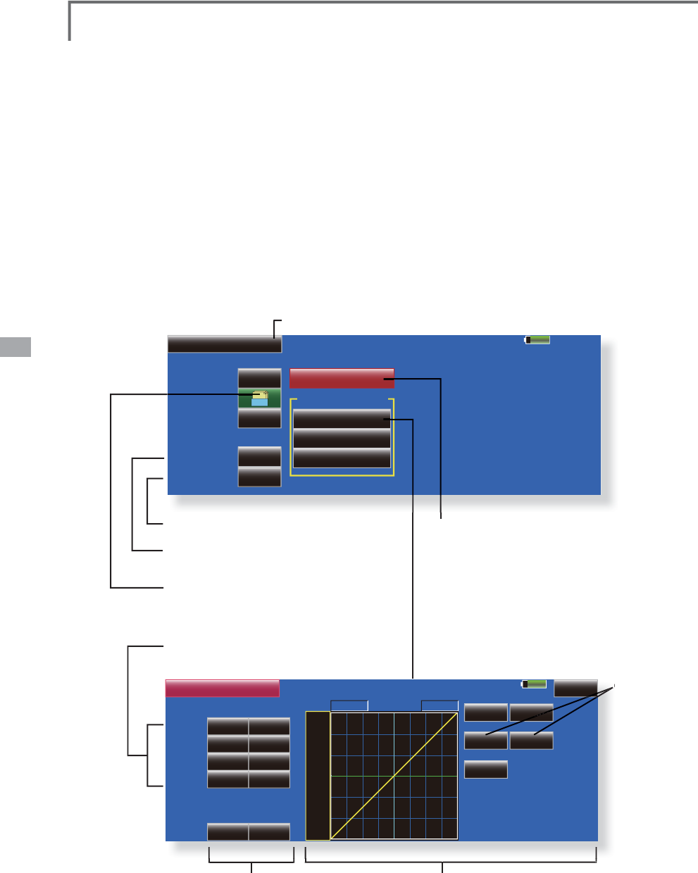
118 <Model Menu (Airplane/Glider Functions)>
85%
Camber Mix Model 1 Condition 1
Camber AFR
Aileron
Flap
Elevator
Group
ON
Switch
ACT/INH INH
Curve and Rate
Gr.
Cond. Delay
OFF
Cut SW
0
85%
+0%
Rate 1 Rate 2
IN Out
POS +0.0%
AIL2
AIL3
AIL4
AIL
Master
Linear Separate
+100.0% +100.0%
Model 1 Condition 1
RATE
Rate A
+0.0%
2íVHW
Rate B
+0.0%
+150
+100
+50
+0
-50
-150
-100
Camber (AIL)
+0%
+0%
+0%
+0%
+0%
+0%
+0%
Speed 00
ŏ
5
H
W
X
UQW
R
0
RGH
O0
H
Q
X
&DPEHU0L[
>
&RUUHVSRQGLQ
J
PRGHOW\SH@$LUSODQH
J
OLGHUDLOHURQVRUPRUH
This function ad
j
usts the AFR (D/R) rate
o
f cam
b
er operat
i
on w
hi
c
h
operates t
h
e w
i
ng
c
am
b
er
(
a
il
erons, cam
b
er f
l
aps,
b
ra
k
e f
l
aps
)
i
n
t
he ne
g
ative and positive directions. The aileron,
fl
ap, an
d
e
l
evator rates can a
l
so
b
e a
dj
uste
d
i
n
d
epen
d
ent
ly
by
curve, an
d
att
i
tu
d
e c
h
an
g
es
c
aused b
y
camber operation can be corrected.
*
Initial setting assigns camber operation to side leve
r
R
ST
(
Mode2
)
LST
(
Mode1
)
.
ŏ
7KHXSGRZQVLGHUDWHVRIWKHDLOHURQÁDSDQG
H
OHYDWRUVHUYRVFDQEHDG
M
XVWHGE\FXUYH:KHQ
the m
i
x
i
n
g
d
i
rect
i
on
i
s reversed by the l
i
nka
g
e,
ad
j
ustments can be made by chan
gi
n
g
the
ŏ7RXFKWKH>&DPEHU0
L
[@EXWWRQ
L
QWKH0RGHO0HQXWRFDOOWKHVHWXS
screen s
h
own
b
e
l
ow
.
*
T
h
e
di
sp
l
ay screen
i
s an examp
l
e. T
h
e actua
l
screen
d
epen
d
s on t
h
e mo
d
e
l
type.
)
m
i
x
i
ng rate polar
i
ty.
ŏ0L[LQJGXULQJÁLJKWFDQEHWXUQHG212))E\
V
HWWLQJDVZLWFK$OZD\V21DW18//VHWWLQJ
ŏ$GHOD\FDQEHVHWIRUHDFKFRQGLWLRQ$FXW
V
ZLWFKZKLFKFDQWXUQ2))WKHGHOD\IXQFWLRQFDQ
b
e set.
ŏ7KHVSHHGR
I
WKHD
L
OHURQ
Á
DSDQGHOHYDWRUVHUYRV
FDQEHVHW
,1V
L
GH287V
L
GH
ŏ&RQGLWLRQGHOD
\
FXWVZLWFK
ŏ&RQGLWLRQGHOD\VHWWLQ
J
ŏ*URXSVLQ
J
OHPRGHVZLWFK
*U6Q
J
O
(For more information, see the descri
p
tion at the
back of this manual.)
ŏ&DPEHU$)5'5VHWXSVFUHHQFDOO
(
For a description of the setting method, refer to the
AFR function.
)
&XUYHUDWHVHWXSVFUHHQ
ŏ0L[LQ
J
FXUYHVHWWLQ
J
(For a description of the curve settin
g
method, see the
d
escr
ip
t
i
on at t
h
e
b
ac
k
of t
hi
s manua
l
.
)
ŏ6HUYRVSHHGVHWW
L
Q
J
(
For a
d
escr
i
pt
i
on of t
h
e sett
i
ng met
h
o
d
, see t
h
e
description at the back of this manual.)
ŏ2YHUDOO
ad
j
ustmen
t
E
\
5DWH$
D
Q
G
5
D
W
H
%
Ra
ŏ$LOHURQUDWHDGMXVWPHQW
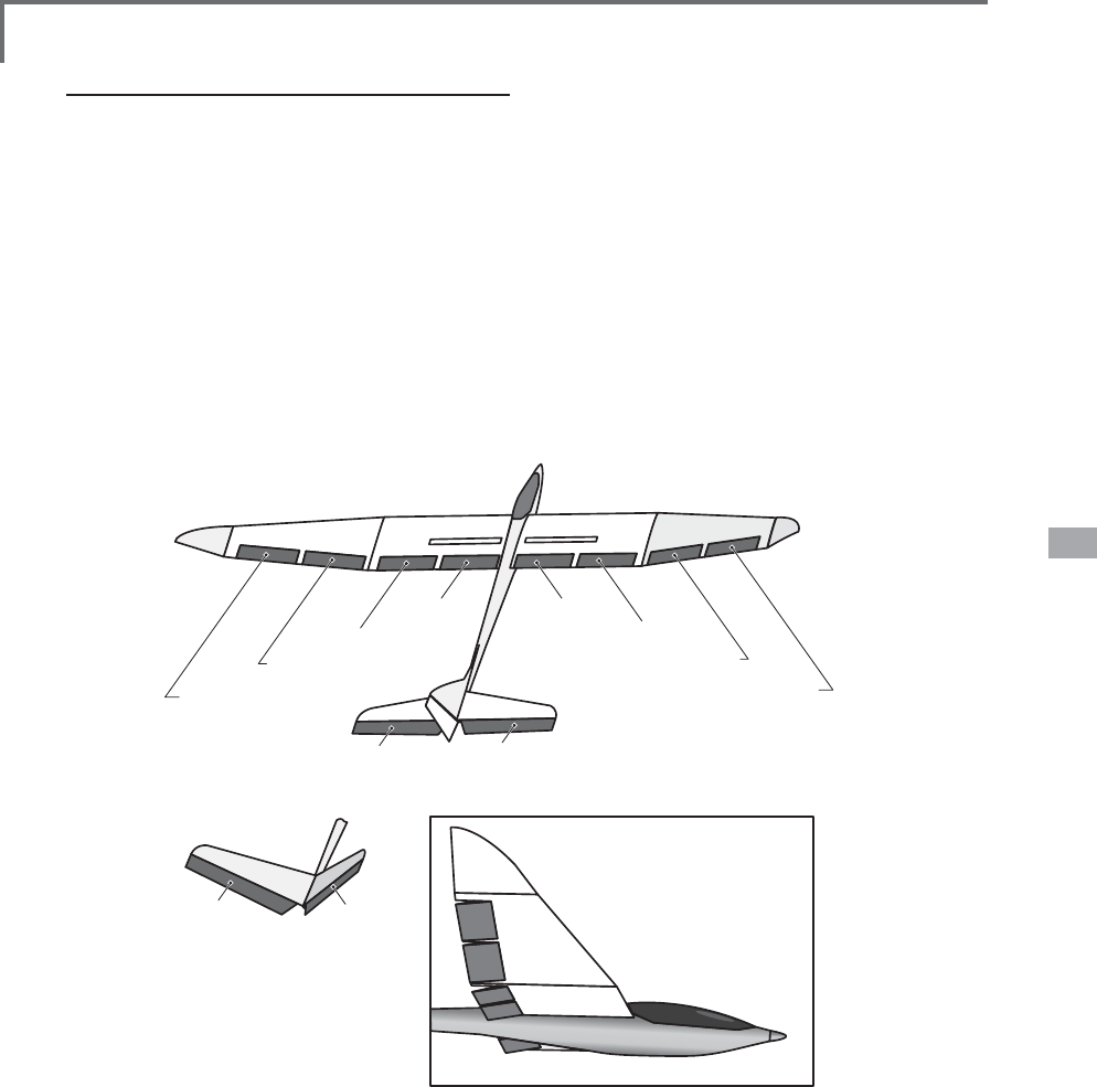
119
<Model Menu (Airplane/Glider Functions)>
AIL 3
(Chip Aileron)
AIL 4
(Chip Aileron)
AIL1
(Main Aileron)
AIL 2
(Main Aileron)
FLP 2
(Camber Flap)
FLP 1
(Camber Flap)
ELEVATOR ELEVATOR 2
at V-TAIL
ELEVATOR ELEVATOR 2
(at AILEVATOR)
FLP 3
(Brake Flap)
FLP 4
(Brake Flap)
6HWWLQJPHWKRG
ŏ7RXFKWKH,1+EXWWRQDQGVHWWKHIXQFWLRQWR$&7
21
ŏ:KHQVHWWLQJDVZLWFKWRXFKWKH>18//@EXWWRQ
to call the <Switch> screen, and then select the
VZLWFKDQGVHWLWV21GLUHFWLRQ$OZD\V21DW
18//VHWWLQJ
(For a description of the switch selection method,
see the description at the back of this manual.)
ŏ:KHQVHWWLQJDFRQGLWLRQGHOD\WRXFKWKH
&RQGLWLRQ'HOD\EXWWRQDQGVHWWKHGHOD\ZLWKWKH
adjustment buttons which appear on the screen.
7KH95RSHUDWLRQPRGHFDQDOVREHVHW
(For a description of condition delay, see the
description at the back of this manual.)
ŏ&DPEHU$)5'5VFUHHQFDOO
7RXFKWKH&DPEHU$)5EXWWRQWRFDOOWKHVHWXS
screen. (For a description of the setup method,
see the description at the back of this manual.)
&XUYHUDWHVHWXSVFUHHQ
ŏ7KHFXUYHDQGUDWHDUHDGMXVWHGE\FDOOLQJWKH
DLOHURQÁDSDQGHOHYDWRUFXUYHUDWHVFUHHQV
The rate and curve of each servo can be set by
calling each screen. (For a description of the
curve setting method, see the description at the
back of this manual.)
The servo speed can also be adjusted.
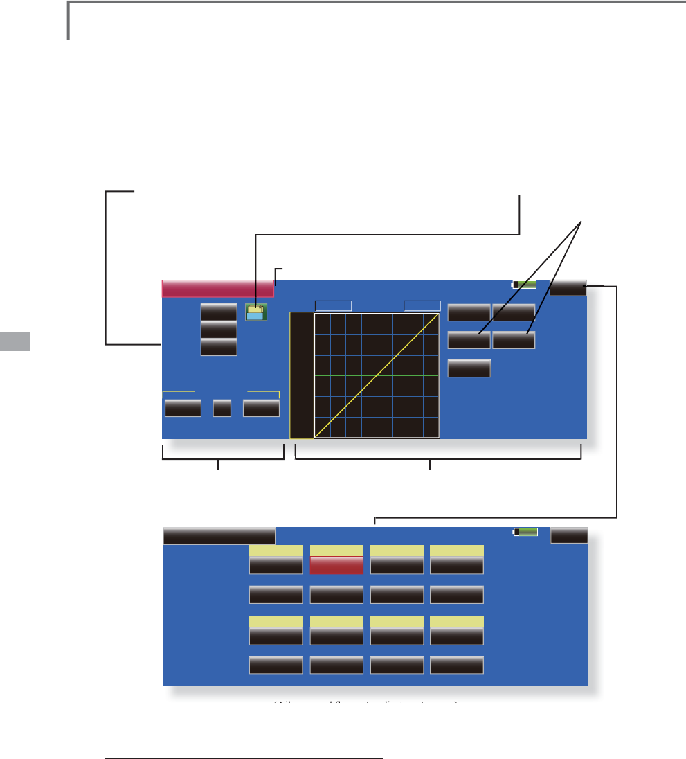
120 <Model Menu (Airplane/Glider Functions)>
85%
ELE to Camber
INH POS +0.0%
Switch
Display
ACT Linear Separate
+100.0% +100.0%
Model 1 Condition 1
Gr. +150
+100
+50
+0
-50
-150
-100
RATE
Rate A
+0.0%
2íVHW
Rate B
+0.0%
Single
OFF
Fine Tuning
NULL 0%
+
( +0%)
1/2
85%
ELE to Camber Model 1 Condition 1 2/2
+0%
( +0% )
AIL3
+0%
( +0% )
AIL
+0%
( +0% )
AIL2
+0%
( +0% )
+0%
( +0% )
+0%
( +0% )
+0%
( +0% )
+0%
( +0% )
+0%
( +0% )
+0%
( +0% )
+0%
( +0% )
+0%
( +0% )
AIL4
+0%
( +0% )
FLP3
+0%
( +0% )
FLP
+0%
( +0% )
FLP2
+0%
( +0% )
FLP4
Rate 1
Rate 2
Rate 1
Rate 2
ŏ
5
H
W
X
UQW
R
0
RGHO
0
H
Q
X
(/(WR&DPEHU >&RUUHVSRQGLQ
J
PRGHOW\SH@$LUSODQH
J
OLGHUDLOHURQVRUPRU
H
T
his function is used when
y
ou want to mix
t
h
e cam
b
er f
l
aps w
i
t
h
e
l
evator operat
i
on. W
h
en
P
L
[
L
Q
J
L
VXVH
G
VRW
K
DWW
K
H
À
DSVDUH
O
RZHUH
G
E\
XS
elevator , lift can be increased.
ŏ
7RXFKWKH
>
(/(WR&DPEHU
@
EXWWRQLQWKH0RGHO
M
enu to call the setu
p
screen shown below.
ŏ$P
L
[
L
QJFXUYHFDQEHVHW
ŏ0
L
[
L
QJGXU
L
QJ
ÁL
JKWFDQEHWXUQHG212))E\
VHWWLQJDVZLWFK$OZD\V21DW18//VHWWLQJ
ŏ7KHPL[LQJUDWHFDQEHÀQHWXQHGE\VHWWLQJD95
ŏ
&XUYHGLVSOD\PRGHVZLWFKLQJ
(Single/Fine tuning/All Cond.)
ŏ
*URXSV
L
QJOHPRGHVZ
L
WFK
L
QJ
(
Gr./Sngl
)
(
For more
i
nformat
i
on, see t
h
e
d
escr
i
pt
i
on
a
t t
h
e
b
ac
k
of t
hi
s manua
l
.
)
ŏ
0
L
[
L
QJFXUYHVHWW
L
QJ
(
For a
d
escr
i
pt
i
on of t
h
e curve sett
i
ng met
h
o
d
, see t
h
e
descri
p
tion at the back of this manual.)
ŏ)LQHWXQLQ
J
95VHWWLQ
J
ŏ
2
YHUDOO
ad
j
ustment by
5
D
W
H
$
D
Q
G
5
D
W
H
%
$LO
HURQVDQ
G
À
DSVUD
W
HD
GM
XV
W
PHQ
W
VFUHHQ
6
HWW
L
Q
J
PHWKR
G
ŏ7RXFKWKH$&7EXWWRQDQGVHWWKHIXQFWLRQWR
$
&721
ŏ:KHQVHWWLQJDVZLWFKWRXFKWKH>18//@EXWWRQRI
the switch to call the <Switch> screen, and then
V
HOHFWWKHVZLWFKDQGVHWLWV21GLUHFWLRQ
$OZD\V
21DW18//VHWW
L
Q
J
ŏ:KHQVHWW
L
Q
J
D95WRXFKWKH)
L
QHWXQ
L
Q
J
18//
b
utton to call the <Sw
i
tch> screen
,
and then
V
HOHFWWKH957KHDG
M
XVWPHQWUDWHDQGDG
M
XVWPHQW
di
r
ec
t
io
n
ca
n
be
se
t
.
7
KH95R
S
HUDWLRQPRGHFDQDOVREHVHOHFWHG
ŏ$P
L
[
L
Q
J
FXUYHFDQDOVREHVHW
(
For a descr
i
pt
i
on o
f
the curve sett
i
n
g
method, see
the descr
i
pt
i
on at the back o
f
th
i
s manual.
)
ŏ7KHFXUYHG
L
VSOD\PRGHFDQEHFKDQJHG
6
L
QJOH'
L
VSOD\VWKHP
L
[
L
QJFXUYHRQO
\
)LQHWXQLQJ'LVSOD\VWKHÀQHWXQLQJ95DGMXVWPHQW
rate
$OO&RQG'LVSOD\VWKHPL[LQ
J
FXUYHRIDOOWKH
FRQGLWLRQV
:KHQFRQGLWLRQVDUHVHW
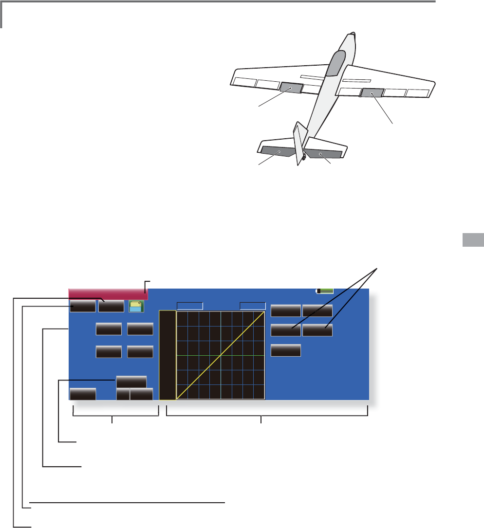
121
<Model Menu (Airplane/Glider Functions)>
ELEVATOR ELEVATOR 2
FLP 2
(Camber Flap)
FLP 1
(Camber Flap)
85%
CamberFLP to ELE
INH OFF POS +0.0%
( +0%) ( +0%)
( +0%) ( +0%)
Linear Separate
+100.0% +100.0%
Model 1 Condition 1
Gr.
+150
+100
+50
+0
-50
-150
-100
RATE
Rate A
+0.0%
2íVHW
Rate B
+0.0%
Fine Tuning Single
NULL +0%
Rate 1 Rate 2
ELE
ELE2
+0% +0%
+0% +0%
ŏ
0L[LQ
J
FXUYHVHWWLQ
J
(For a description of the curve settin
g
method, see the
d
escri
p
tion at the back of this manual.)
ŏ)
L
QHWXQ
L
QJ95VHWW
L
Q
J
ŏ5HWXUQWR0R
G
H
O
0HQ
X
&DPEHU)/3WR(/( >&RUUHVSRQGLQ
J
PRGHOW\SH@$LUSODQH
J
OLGHUDLOHURQVIODSR
U
m
o
r
e
This mixin
g
is used to correct chan
g
es (elevator
GL
UHFW
L
RQ
JHQHUDWH
G
Z
K
HQW
K
HFDP
E
HU
À
DSV
VSHH
G
À
DSV
DUHXVH
G
ŏ
7KHHOHYDWRUVHUYRVXSV
L
GHGRZQV
L
GHUDWHFDQEH
D
G
M
XVWHG:KHQWKHP
L
[
L
QJG
L
UHFW
L
RQ
L
VUHYHUVHG
by the linkage, adjustments can be made by
c
hanging the mixing rate polarity.
ŏ
$PL[LQ
J
FXUYHFDQEHVHW
ŏ
0L[LQ
J
GXULQ
J
ÁL
J
KWFDQEHWXUQHG212))E\
VHWWLQ
J
DVZLWFK
$OZD\V21DW18//VHWWLQ
J
ŏ
7KHP
L
[
L
Q
J
UDWHFDQEH
À
QHWXQHGE\VHWW
L
Q
J
D95
ŏ7RXFKWKH>&DPEHU)/3WR(/(@EXWWRQ
L
Q
t
h
e Mo
d
e
l
Menu to ca
ll
t
h
e setup screen
s
h
own
b
e
l
ow
.
*The display screen is an example. The actual screen
d
epends on the model t
y
pe.
ŏ&XUYHGLVSOD\PRGHVZLWFKLQ
J
(
Single/Fine tuning/All Cond.)
ŏ(OHYDWRUUDWHDG
M
XVWPHQ
W
ŏ*URXSVLQ
J
OHPRGHVZLWFKLQ
J
(
Gr./Sn
g
l
)
(
For more
i
nformat
i
on, see t
h
e
d
escr
i
pt
i
on
at the back of this manual.
)
ŏ
2
YHUDOO
ad
j
ustmen
t
E
\
5DWH$
D
Q
G
5
D
W
H
%
6
HWW
L
Q
J
PHWKR
G
ŏ7RXFKWKH$&7EXWWRQDQGVHWWKH
I
XQFW
L
RQWR
$&721
ŏ:KHQVHWWLQJDVZLWFKWRXFKWKHVZLWFKEXWWRQ
to call the <Switch> screen, and then select the
V
ZLWFKDQGVHWLWV21GLUHFWLRQ
$OZD\V21DW
18//VHWW
L
Q
J
(
For a descr
i
pt
i
on o
f
the sw
i
tch sett
i
n
g
method,
s
ee the descr
i
pt
i
on at the back o
f
the manual.
)
ŏ7RXFKWKHHOHYDWRUVHUYRVOH
I
WDQGU
L
JKWEXWWRQV
a
nd adjust the mixing rate with the adjustment
b
uttons dis
p
la
y
ed on the screen.
*
W
h
en t
h
e m
i
x
i
ng
di
rect
i
on
i
s reverse
d
b
y t
h
e
li
n
k
age,
adjustments can be made by changing the mixing rate
polarity.
ŏ:KHQVHWW
L
Q
J
D95WRXFKWKH)
L
QHWXQ
L
Q
J
18//
b
utton to call the <Sw
i
tch> screen
,
and then
VH
O
HF
WWK
H
95
7KH95R
S
HUDWLRQPRGHFDQEHVHOHFWHG
ŏ$PL[LQJFXUYHFDQEHVHW
(For a description of the curve setting method, see
the description at the back of this manual.
)
ŏ7KHFXUYHRSHUDWLRQPRGHFDQEHFKDQ
J
HG
6
L
Q
J
OH'
L
VSOD\VRQO\WKHP
L
[
L
Q
J
FXUYH
)
L
QH7XQ
L
Q
J
'
L
VSOD\VWKHDG
M
XVWPHQWUDWHR
I
WKH
À
QHWXQ
L
Q
J
9
5
$OO&RQG'
L
VSOD\VWKHP
L
[
L
QJFXUYHR
I
DOOWKH
cond
i
t
i
ons
(
when cond
i
t
i
ons are set
)
R
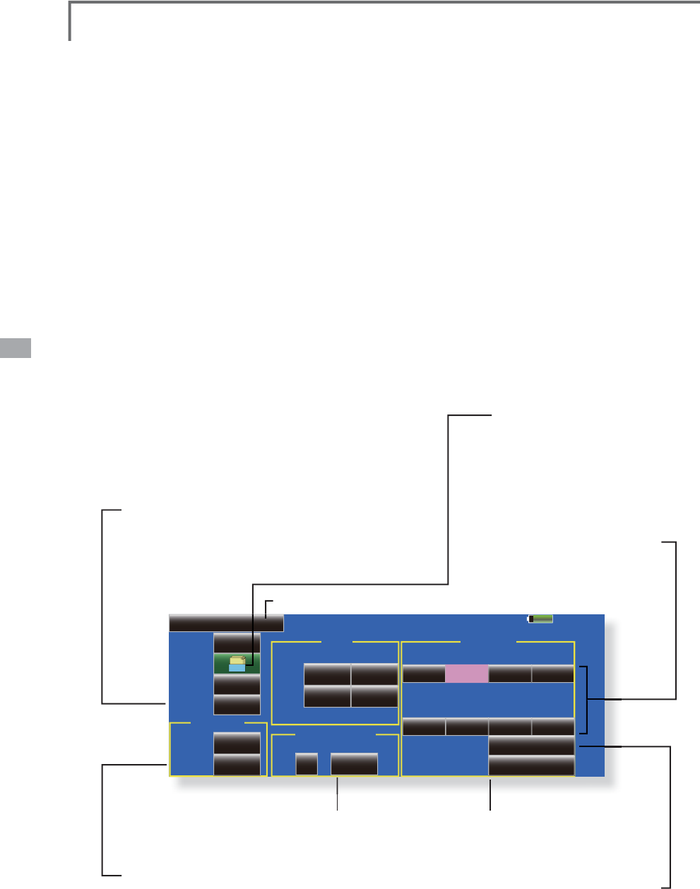
122 <Model Menu (Airplane/Glider Functions)>
85%
%XWWHUs\ Model 1 Normal
+0% +0% +0% +0%
Mixing Rate
Speed
'LíHUHQWLDO5DWH
&RQG'HOD\
2íVHW 15%
Group
OFF
Switch
Cut SW OFF
0
00
00
0%+
'HOD\
ACT
AIL
In Out AIL3 AIL2 AIL4AIL
+0% +0% +0% +0%
FLP3 FLP2 FLP4FLP
FLP
INH
Gr.
%XWWHUs\$)5
ELE Setting
%XWWHUÀ\ >&RUUHVSRQGLQ
J
PRGHOW\SH@*OLGHUDLOHURQVRUPRU
H
T
his function allows
p
owerful brake o
p
eration
b
y s
i
mu
l
taneous
l
y ra
i
s
i
ng t
h
e
l
eft an
d
r
i
g
h
t
a
il
erons an
d
l
ower
i
n
g
t
h
e f
l
aps
(
cam
b
er f
l
ap,
E
UDNHÀD
S
Thi
s sett
i
n
g
w
ill
a
ll
ow t
h
e a
il
erons to
b
e ra
i
se
d
w
hile the flaps are simultaneously lowered.
%XWWHU
À
\
&URZ
SUR
G
XFHVDQH[WUHPH
O
\HI
¿
F
L
HQW
l
an
di
n
g
conf
ig
urat
i
on
by
accomp
li
s
hi
n
g
t
h
e
IROORZLQJ
1.
Slow the a
i
rcra
f
t’s veloc
i
ty.
2
. Prov
i
de washout at the w
i
ng t
i
ps to reduce
the tendency to t
i
p stall
.
&UHDWHPRUHO
LI
WWRZDUGWKHFHQWHUR
I
WKH
Z
L
QJDOORZ
L
QJ
L
WWR
Á
\DWDVORZHUVSHH
G
ŏ0L[LQ
J
GXULQ
J
ÁL
J
KWFDQEHWXUQHG212))E\
VHWW
L
Q
J
DVZ
L
WFK
$OZD\V21DW18//VHWW
L
Q
J
ŏ7KHEXWWHU
Á
\RSHUDW
L
RQUH
I
HUHQFHSR
L
QWFDQEH
R
II
VHW:KHQWKH2
II
VHWEXWWRQ
L
VWRXFKHGZKHQ
operated to the pos
i
t
i
on to be changed, the
UHIHUHQFH
S
RLQWLVRIIVHW,IWKHUHIHUHQFH
S
RLQWLV
offset too much, unex
p
ected o
p
eration ma
y
be
p
erformed.
ŏ7KHDLOHURQVÁDSVDQGHOHYDWRUVRSHUDWLRQVSHHG
FDQEHDG
M
XVWHG
,1VLGH287VLGH
ŏ$GHOD\FDQEHVHW
I
RUHDFKFRQG
L
W
L
RQ$FXW
VZ
L
WFKZK
L
FKFDQWXUQ2))WKHGHOD\
I
XQFW
L
RQFDQ
a
l
so
be
se
t
.
ŏ7KHG
LII
HUHQW
L
DOUDWHFDQEHDG
M
XVWHG
*
W
h
en servo
bi
n
di
ng occurs w
h
en sett
i
ng t
h
e a
il
erons an
d
À
DSV
L
Q
E
XWWHU
À
\P
L
[
L
QJXVHW
K
H$)5IXQFW
L
RQWRD
GM
XVWW
K
H
r
udder angle.
ŏ5HWXUQWR0R
G
H
O
0HQ
X
ŏ
:KHQR
II
VHWW
L
QJWKHEXWWHU
I
O\RSHUDW
L
RQ
r
e
f
erence po
i
nt, operate to the po
i
nt you
Z
DQWWRFKDQJHDQGWKHQWRXFKWKH2
II
VHW
b
utton. The reference point displays 0
%
.
:
KHQ><HV@
L
VWRXFKHGWKHUH
I
HUHQFHSR
L
QW
L
V
F
KDQJHG7KHQ
L
V,Q
L
W
L
DO
L
]HGHOHYDWRUFXUYH"
i
s heard,
i
t chooses
i
n wh
i
ch
.
ŏ'LIIHUHQWLDOUDWH
a
d
j
ustmen
t
ŏ7RHOHYDWRUFRUUHFWLRQ
s
e
t
up scree
n
ŏ
&DOOVWKH%XWWHU
Á
\$)5
'5
VHWXSVFUHHQ
(
For a
d
escr
i
pt
i
on of t
h
e sett
i
n
g
met
h
o
d
, see t
h
e
d
escr
i
pt
i
on at
th
e
b
ac
k
of t
hi
s manua
l
.
)
ŏ
$
L
OHURQDQG
Á
DSVHUYRVVSHHG
s
ett
i
n
g
(
For a
d
escr
i
pt
i
on of t
h
e sett
i
ng met
h
o
d
,
see t
h
e
d
escr
i
pt
i
on at t
h
e
b
ac
k
of t
hi
s
m
anua
l
.
)
ŏ
&RQGLWLRQGHOD\VHWWLQ
J
DQGFXW
s
witch settin
g
(
For a
d
escr
i
pt
i
on of t
h
e sett
i
n
g
met
h
o
d
, see t
h
e
d
escr
i
pt
i
on at t
h
e
b
ac
k
of t
hi
s manua
l
.
)
ŏ
*URXSVLQJOHPRGHVZLWFKLQJ
(
Gr./Sn
g
l
)
(For more information, see the descri
p
tion
a
t the back of this manual.
)
ŏ7RXFKWKH0
L
[
L
QJ5DWH$,/DQG
)/3EXWWRQVDQGDG
M
XVWWKH
m
i
x
i
ng rates
.
ŏ7RXFKWKH>%XWWHU
Á
\@EXWWRQ
L
QWKH0RGHO0HQX
to ca
ll
t
h
e setup screen s
h
own
b
e
l
ow.
(The display screen is an example. The actual screen depends
o
n the model type. The screen shown below is for 4 ailerons
D
QGÀD
S
V
ŏ
7RXFKWKH$
&
7EXWWRQDQGVHWWKHIXQFWLRQWR
$
&7
21
ŏ
:KHQVHWWLQ
J
DVZLWFKWRXFKWKH6:,7&+
>
18//
@
EXWWRQWRFDOOWKH6ZLWFK!VFUHHQDQG
W
KHQVHOHFWWKHVZLWFKDQGVHWLWV
2
1GLUHFWLRQ
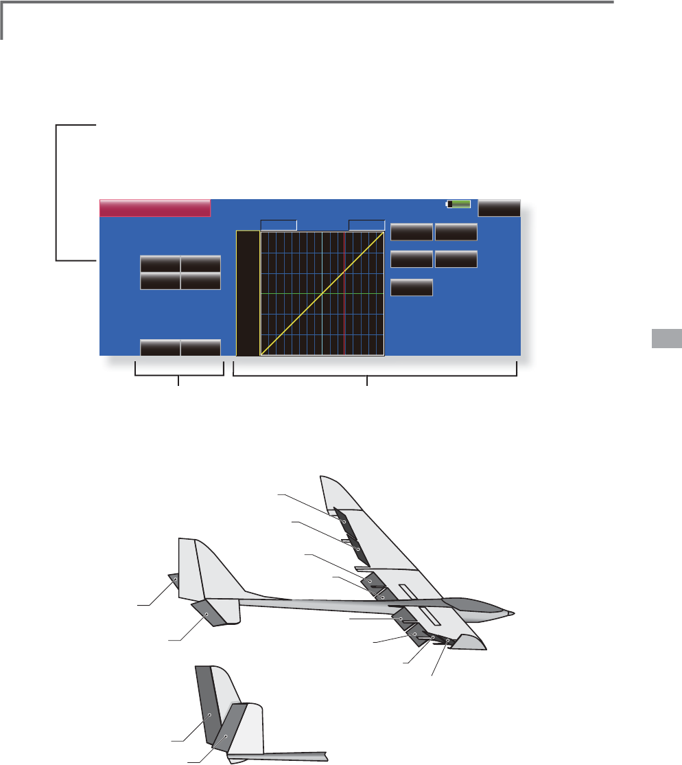
123
<Model Menu (Airplane/Glider Functions)>
AIL 3
(Chip Aileron)
AIL 4
(Chip Aileron)
AIL1
(Main Aileron)
AIL 2
(Main Aileron)
FLP 2
(Camber Flap)
FLP 1
(Camber Flap)
ELEVATOR
ELEVATOR 2
at V-TAIL
ELEVATOR
ELEVATOR 2
(at AILEVATOR)
FLP 3
(Brake Flap)
FLP 4
(Brake Flap)
85%
+0%
Rate 1 Rate 2
IN Out
POS +0.0%
ELE2
ELE
Return
Linear Separate
+100.0% +100.0%
Model 1 Normal
RATE
Rate A
+0.0%
2íVHW
Rate B
+0.0%
+150
+100
+50
+0
-50
-150
-100
%XWWHUs\
+0%
+0%
+0%
Speed 00
ELE Setting
(
[ELE Setup] screen
)
ŏ
7RXFKWKH(/(FRUUHFWLRQUDWHEXWWRQVDQG
a
d
j
ust the rates w
i
th the ad
j
ustment buttons
di
splayed on the screen
.
ŏ0L[LQ
J
FXUYHVHWWLQ
J
(
For a description of the curve settin
g
method, see the
descri
p
tion at the back of this manual.)
ŏ6HUYRVSHHGVHWWLQ
J
(
For a description of the setting method, see the
descri
p
tion at the back of this manual.)
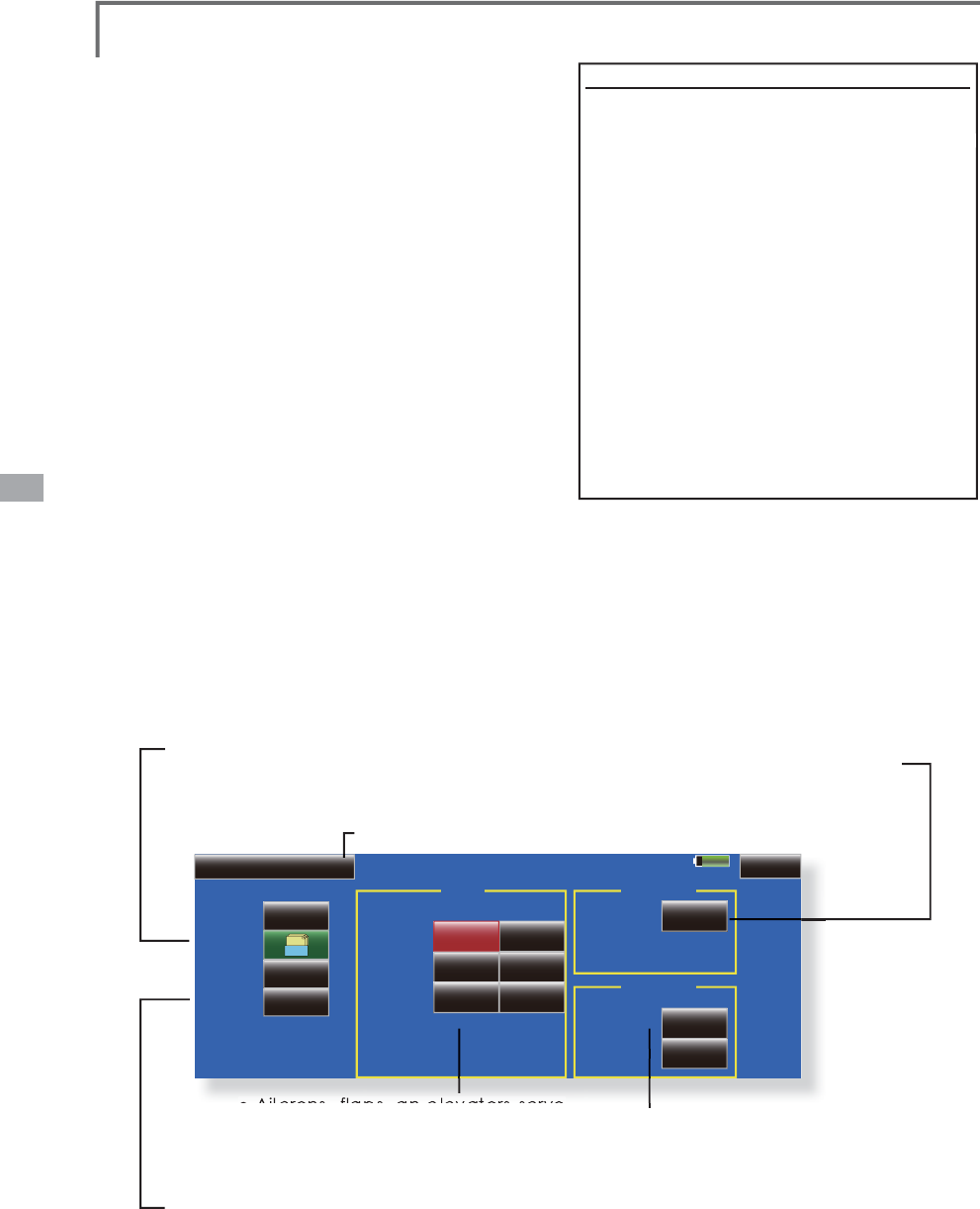
124 <Model Menu (Airplane/Glider Functions)>
85%
Model 1 Normal
Speed
Cond. Delay
Mode Manual
Group
ON
Switch
Cut Switch OFF
0
00
00
Delay
Fine Tuning
NULL
Control
ACT/INH
AIL
In Out
FLP
00
ELE
INH
Gr.
1/2
Trim Mix 1
ŏ
5
H
W
X
UQW
R
0
RGH
O0
H
Q
X
ŏ*URXSVLQ
J
OHPRGHVZLWFKLQ
J
(
Gr./Sn
g
l
)
(
For more information, see the
descri
p
tion at the back of this manual.)
ŏ
:KHQXVLQ
J
DILQHWXQLQ
J
95WRXFKWKLV
b
utton to call the <
S
witch> screen
.
ŏ
&RQGLWLRQGHOD\VHWWLQ
J
IRUD
d
escription of the settin
g
method,
s
ee the descri
p
tion at the back of
t
his manual
)
and cut switch settin
g.
ŏ
$LOHURQV
IODSV
DQ
HOHYDWRUV
VHUYR
s
peed settin
g
(
For a
d
escr
i
pt
i
on of t
h
e sett
i
n
g
met
h
o
d
, see t
h
e
d
escr
i
pt
i
on at t
h
e
b
ac
k
of t
hi
s manua
l
.
)
ŏ0DQXDO
$XWRPRGHVHOHFWLR
Q
0
DQXDO6ZLWFKHVWKHIXQFWLRQ212))E
\
VZLWF
K
Auto: Trim mix function call can be linked to a stick,
etc. A stick switch, etc. se
p
arate from the function
2
1
2))VZLWFKLVVHW
(
Trim mix setup pa
g
e 1/2
)
h
7ULP0L[ >&RUUHVSRQGLQ
J
PRGHOW\SH@*OLGHUDLOHURQVRUPRUH
T
hese functions call the ailerons, elevators, and
À
DSV
FDP
E
HU
À
DSV
E
UD
N
H
À
DSV
WU
L
PRIIVHWUDWHV
S
UHVHWDFFRU
GL
Q
J
WRW
K
H
ÀLJK
WVWDWH
Th
e amount of a
il
erons, e
l
evator, an
d
f
l
aps
FDP
E
HU
À
DS
E
UD
N
H
À
DS
WU
L
PRIIVHWFDQ
E
HVHWWR
a switch.
As an exam
p
le
7ULP 0L[
can be set u
p
for
O
DXQFKLQJZLWKVSHHGÀDSVDQGDLOHURQVGURSSHG
an
d
a s
li
g
h
t amount of up e
l
evator.
7
U
L
PP
L
[
can be used for hi
g
h speed fl
y
in
g
, with both
DLOHURQVDQGVSHHGÀDSVUHÀH[HGVOLJKWO\DQGDELW
o
f
dow
n
elev
at
o
r
.
Th
e tr
i
m funct
i
ons can
b
e act
i
vate
d
d
ur
i
ng
ÀLJK
W
E\
VHWW
L
Q
J
DVZ
L
WF
K
7RSUHYHQWVX
GG
HQWU
L
P
FKDQ
J
HVZKHQVZLWFKLQ
J
ÀL
J
KWFRQGLWLRQVDGHOD
\
can
b
e set to prov
id
e a smoot
h
trans
i
t
i
on
b
etween
t
h
e two. Tr
i
m M
i
x 2 w
ill
h
ave pr
i
or
i
t
y
over Tr
i
m
M
ix 1.
ŏ7RXFKWKH
>
7ULP0L[
@
EXWWRQLQWKH0RGHO0HQXWRFDOOWKHVHWX
S
VFUHHQVKRZQ
be
l
o
w
.
(
The displa
y
screen is an example. The actual screen depends on the model t
y
pe. The screen shown below is for 4
DLOHURQVDQGÀD
S
V
(
Touch the [1/2] button to sw
i
tch to pa
g
e 2.
)
ŏ7RXFKWKH$&7EXWWRQDQGVHWWKH
I
XQFW
L
RQWR$&7
21
ŏ:KHQVHWW
L
Q
J
DVZ
L
WFKWRXFKWKH6Z
L
WFKEXWWRQWRFDOOWKH6Z
L
WFK!VFUHHQDQGWKHQ
VHOHFWWKHVZ
L
WFKDQGVHW
L
WV21G
L
UHFW
L
RQ
$OZD\V21DW18//VHWW
L
Q
J
(
For a
d
escr
i
pt
i
on of t
h
e sw
i
tc
h
se
l
ect
i
on met
h
o
d
, see t
h
e
d
escr
i
pt
i
on at t
h
e
b
ac
k
of t
hi
s manua
l
.
)
(
[DP
SOH
7RXFKWKH$
&
7EXWWRQDQGVHWWKHWULPPL[IXQFWLRQ
W
R
>2
1
@
*
W
h
en separat
i
ng t
h
e sett
i
ngs for eac
h
con
di
t
i
on, touc
h
t
h
e
group mode button and set it to [Sngl].
6HOHFWWKH212))VZ
L
WFK
6
H
O
HFWW
K
H
>
0DQXD
O@
RU
>
$XWR
@
PR
G
H
,QWKH>$XWR@PRGHDOVRVHOHFWDQDXWR6:7K
L
V
s
w
i
tch can be l
i
nked to a st
i
ck
,
etc
.
<Sp
ee
d>
,Q7KHRSHUDW
L
RQVSHHGDWVZ
L
WFK21FDQEHVHW
2XW7KHUHWXUQVSHHGDWVZLWFK2))FDQEHVHW
<
F
i
ne Tun
i
ng
>
T
he offset rate can be varied in the Fine Tunin
g
QXPHULFUDQ
J
HVHWDWVFUHHQ>@E\95HWF
s
election
.
&RQG
L
W
L
RQ'HOD\!
:KHQÁL
J
KWFRQGLWLRQVDUHVHWWKHRSHUDWLRQVSHHG
FDQEHVHWIRUHDFKFRQGLWLRQ&RQGLWLRQGHOD
\
o
p
eration can be interru
p
ted and each rudde
r
q
uickly returned to its original position by selecting a
cu
t
s
w
i
t
c
h
.
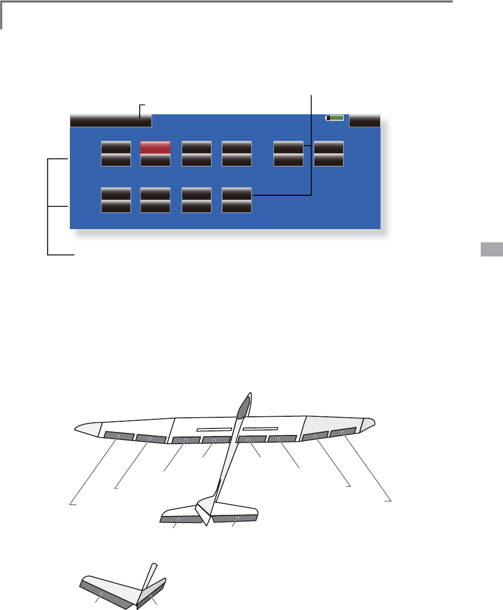
125
<Model Menu (Airplane/Glider Functions)>
AIL 3
(Chip Aileron)
AIL 4
(Chip Aileron)
AIL1
(Main Aileron)
AIL 2
(Main Aileron)
FLP 2
(Camber Flap)
FLP 1
(Camber Flap)
ELEVATOR ELEVATOR 2
at V-TAIL
ELEVATOR ELEVATOR 2
(at AILEVATOR)
FLP 3
(Brake Flap)
FLP 4
(Brake Flap)
85%
+0%
AIL 3
Tuning
2íVHW
2/2
0RGHO 1RUPDO
7ULP0L[
+0%
( +0%)
+0%
AIL
+0%
( +0%)
+0%
AIL 2
+0%
( +0%)
+0%
AIL 4
+0%
( +0%)
+0%
FLP 3
Tuning
2íVHW
+0%
( +0%)
+0%
FLP
+0%
( +0%)
+0%
FLP 2
+0%
( +0%)
+0%
FLP 4
+0%
( +0%)
+0%
ELE
+0%
( +0%)
+0%
ELE 2
+0%
( +0%)
ŏ5
H
W
X
UQW
R
0
RGH
O0
H
Q
X
ŏ
:KHQDÀQHWXQLQ
J
95LVVHWRQWKHQH[WSD
J
H
WKHDLOHURQV
D
QGÁDSVWULPUDWHVFDQEHDG
M
XVWHG
T
ouch the correspondin
g
button and ad
j
ust the rate with the
a
d
j
ustment buttons displayed on the screen
.
ŏ
7KHDLOHURQVIOD
S
VDQGHOHYDWRUV
o
ffset rate can be ad
j
usted
.
T
ouch the correspondin
g
button
a
nd ad
j
ust the rate with the
a
d
j
ustment buttons displayed on
t
h
e
sc
r
ee
n
.
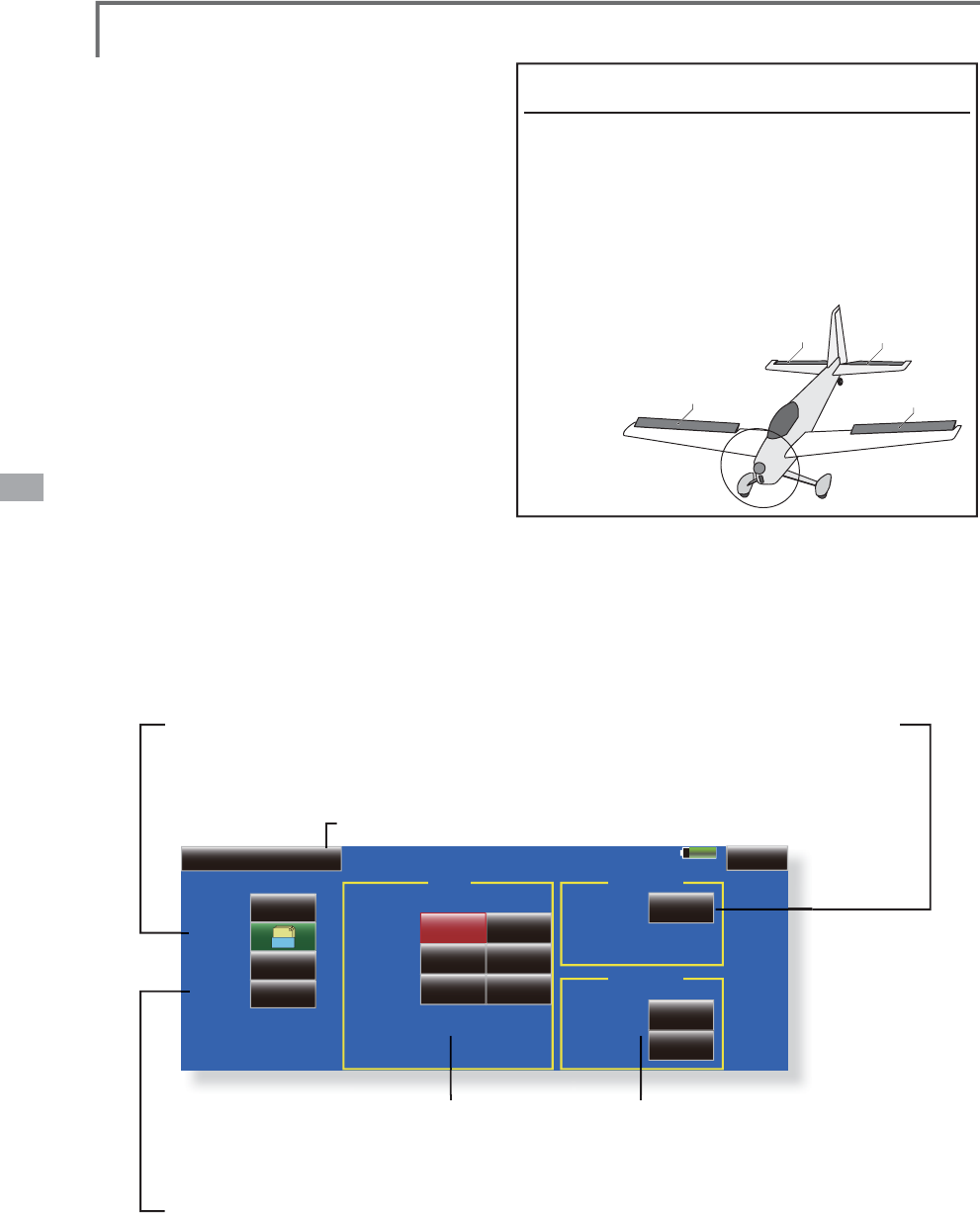
126 <Model Menu (Airplane/Glider Functions)>
85%
Model 1 Normal
Speed
Cond. Delay
Mode Manual
Group
ON
Switch
Cut Switch OFF
0
00
00
Delay
Fine Tuning
NULL
Control
ACT/INH
AIL
In Out
FLP
00
ELE
INH
Gr.
1/2
Airbrake
ŏ
5
H
W
X
UQW
R
0
RGH
O0
H
Q
X
ŏ
*URXSVLQ
J
OHPRGHVZLWFKLQ
J
(
Gr./Sn
g
l
)
(
For more information, see the
descri
p
tion at the back of this manual.)
ŏ:KHQXVLQ
J
DILQHWXQLQ
J
95WRXFKWKLV
button to call the <
S
witch> screen
.
ŏ&RQGLWLRQGHOD\VHWWLQ
J
IRUD
description of the settin
g
method,
see the descri
p
tion at the back of
this manual
)
and cut switch settin
g.
ŏ$LOHURQVIOD
S
VDQHOHYDWRUVVHUYR
speed settin
g
(
For a
d
escr
i
pt
i
on of t
h
e sett
i
n
g
met
h
o
d
, see t
h
e
d
escr
i
pt
i
on at t
h
e
b
ac
k
of t
hi
s manua
l
.
)
ŏ0DQXDO$XWRPRGHVHOHFW
L
R
Q
0
DQXDO6Z
L
WFKHVWKH
I
XQFW
L
RQ212))E\VZ
L
WF
K
Auto: Tr
i
m m
i
x
f
unct
i
on call can be l
i
nked to a st
i
ck
,
etc. A st
i
ck sw
i
tch, etc. se
p
arate
f
rom the
f
unct
i
on
2
12))VZ
L
WFK
L
VVHW
(
Airbrake setup screen 1/2
)
G
M
h
$LUEUDNH >&RUUHVSRQGLQ
J
PRGHOW\SH@$LUSODQH
J
HQHUD
O
T
his function is used when an air brake is
n
ecessary w
h
en
l
an
di
ng or
di
v
i
ng, etc.
T
he
p
reset elevators and fla
p
s (camber fla
p
,
b
ra
k
e f
l
ap
)
offset amount can
b
e act
i
vate
d
b
y a
s
w
i
tc
h
.
Th
e offset amount of t
h
e a
il
eron
,
e
l
evator
,
an
d
flap servos can be ad
j
usted as needed. Also the
VS
HHGRIWKHDLOHURQHOHYDWRUDQGÀD
S
VHUYRVFDQ
b
e a
dj
uste
d
.
(
IN s
id
e
/
OUT s
id
e
)
A
d
e
l
ay can
b
e se
t
for each condition, and a Cut switch which will
turn OFF the delay can be chosen. Trim amounts
FDQ
E
HI
L
QHWXQH
G
E
\VHWW
L
QJD95<RXFDQD
O
VR
s
et the Auto Mode, which will link Airbrake to a
s
tick, switch, or dial. A se
p
arate stick switch o
r
di
a
l
can a
l
so
b
e set as t
h
e ON
/
OFF sw
i
tc
h
.
ŏ
7RXFKWKH>$
L
UEUDNH@EXWWRQ
L
QWKH0RGHO0HQXWRFDOOWKHVHWXSVFUHHQVKRZQ
b
elow.
(
The d
i
splay screen
i
s an example. The actual screen depends on the
P
RGHOW\SH7KHVFUHHQVKRZQEHORZ
L
V
I
RUD
L
OHURQVDQG
Á
DSV
ŏ
7RXFKWKH$&7EXWWRQDQGVHWWKH
I
XQFW
L
RQWR$&7
21
ŏ
:KHQVHWW
L
QJDVZ
L
WFKWRXFKWKH6Z
L
WFKEXWWRQWRFDOOWKH6Z
L
WFK!VFUHHQDQG
W
KHQVHOHFWWKHVZ
L
WFKDQGVHW
L
WV21G
L
UHFW
L
RQ
$OZD\V21DW18//VHWW
L
QJ
(For a descri
p
tion of the switch selection method, see the descri
p
tion at the back of this manual.)
6
HWWLQJH[DPSOHIRU)$DQGRWKHUÀDSHURQ
VSHF
L¿
FDW
L
RQV
:KHQDLOHURQVPRGHOW\SHVHOHFWHG
(
Page 2/2
)
2II
VHWUDWH
$,/>a
@$,/>a
@(/(>a
@
1RWH7
K
H
L
QSXWQXPHU
L
FVDUHH[DPS
O
HV$
GM
XVWW
K
HWUDYH
O
WRPDWF
K
W
K
H
f
uselage.
(
Pa
g
e 1/2
)
$
&
7
>2
1
@
G
roup: [Sn
g
l]
6ZLWFK
>
6&&
@
M
ode: [Manual]
AIL1
FLP 2
ELEVATOR
ELEVATOR 2
(at AILEVATOR)
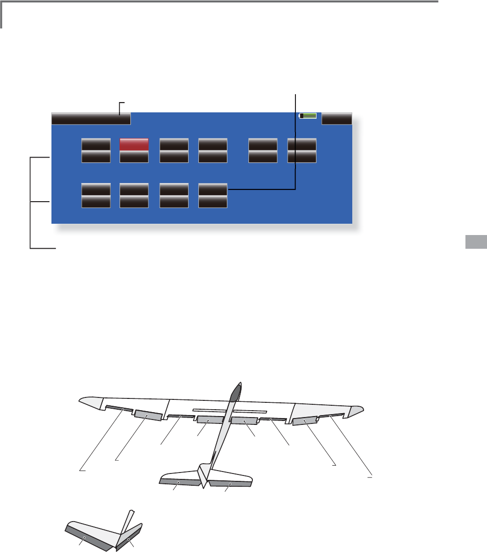
127
<Model Menu (Airplane/Glider Functions)>
AIL 3
(Chip Aileron) AIL 4
(Chip Aileron)
AIL1
(Main Aileron) AIL 2
(Main Aileron)
FLP 2
(Camber Flap)
FLP 1
(Camber Flap)
ELEVATOR ELEVATOR 2
at V-TAIL
ELEVATOR ELEVATOR 2
(at AILEVATOR)
FLP 3
(Brake Flap)
FLP 4
(Brake Flap)
85%
+0%
AIL 3
Tuning
2íVHW
2/2
0RGHO 1RUPDO
+0%
( +0%)
+0%
AIL
+0%
( +0%)
+0%
AIL 2
+0%
( +0%)
+0%
AIL 4
+0%
( +0%)
+0%
FLP 3
Tuning
2íVHW
+0%
( +0%)
+0%
FLP
+0%
( +0%)
+0%
FLP 2
+0%
( +0%)
+0%
FLP 4
+0%
( +0%)
+0%
ELE
+0%
( +0%)
+0%
ELE 2
+0%
( +0%)
$LUEUDNH
ŏ
5
H
W
X
UQW
R
0
RGH
O0
H
Q
X
ŏ
:KHQDÀQHWXQLQ
J
95LVVHWRQWKHQH[WVFUHHQ
WKHDLOHURQ
D
QGÁDSWULPUDWHVFDQEHDG
M
XVWHG7RXFKWKHFRUUHVSRQGLQ
J
b
utton and ad
j
ust the rates with the ad
j
ustment buttons
d
is
p
la
y
ed on the screen
.
ŏ
7KHDLOHURQÁD
S
DQGHOHYDWRURIIVHW
r
ates can be ad
j
usted
.
T
ouch the correspondin
g
button
a
nd ad
j
ust the rate with the
a
d
j
ustment buttons displayed on
t
h
e
sc
r
ee
n
.
E
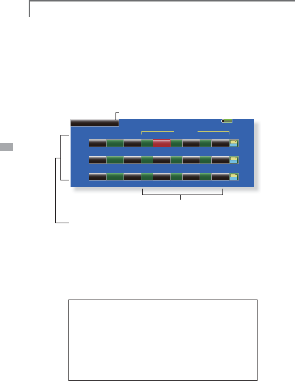
128 <Model Menu (Airplane/Glider Functions)>
85%
INH GY AVCS AVCS
ACT Type
OFF
Switch
Rate1
Model 1
Gyro
0%
Gyro Gyro2 Gyro3
0% AVCS 0%
Condition 1
Gr.
INH GY AVCS AVCS
ACT Type
OFF
Switch
Rate2 0%
Gyro Gyro2 Gyro3
0% AVCS 0%
Gr.
INH GY AVCS AVCS
ACT Type
OFF
Switch
Rate3 0%
Gyro Gyro2 Gyro3
0% AVCS 0%
Gr.
Gyro Rate
ŏ
5
H
W
X
UQW
R
0
RGH
O0
H
Q
X
*\UR >&RUUHVSRQGLQ
J
PRGHOW\SH@$LUSODQH
J
OLGHU
J
HQHUDO
7
KLVIXQFWLRQLVXVHGZKHQD*<$6HULHV
J\
UR
i
s use
d
to sta
bili
ze t
h
e fuse
l
age att
i
tu
d
e. T
h
e
VHQV
L
W
L
Y
L
W
\
DQ
G
RSHUDW
L
RQPR
G
H
1RUPD
O
PR
G
H
*<
mode
)
can be switched with a switch.
ŏ7KUHHUDWHV5DWH5DWH5DWHFDQEH
s
witched.
ŏ8SWRD[HV
*\UR*\UR*\UR
FDQEH
s
imultaneously controlled.
*Initial settin
g
does not assi
g
n a sensitivit
y
channel. Use the
ŏ7RXFKWKH
>
*
\
UR
@
EXWWRQLQWKH0RGHO0HQX
to ca
ll
t
h
e setu
p
screen s
h
own
b
e
l
ow
.
Funct
i
on menu of t
h
e L
i
n
k
age Menu to ass
i
gn t
h
e sens
i
t
i
v
i
ty
FKDQQHO*\UR*\UR*\URXVHGWRDYDFDQWFKDQQHO
be
f
o
r
e
han
d.
Set [ACT] an
d
[Tr
i
m] ot
h
er t
h
an Funct
i
on to [NULL].
ŏ7KHRSHUDWLRQPRGH
$9&6125
DQGVHQVLWLYLW\RI
WKHD[HV*
\
UR*
\
UR*
\
URFDQEHVHW
ŏ*URXSVLQ
J
OHPRGHVZLWFKLQ
J
(
Gr./Sn
g
l
)
(
For more
i
nformat
i
on, see t
h
e
d
escr
i
pt
i
on
at t
h
e
b
ac
k
of t
hi
s manua
l
.
)
ŏ7KUHHUDWHV
5DWH5DWH5DWH
FDQEHXVHG
ŏ7RXFKWKH$&7EXWWRQR
I
WKHUDWHWREHXVHGDQGVHWWKH
I
XQFW
L
RQWR
$&7
>21@RU>2))@
ŏ:KHQD)XWDED*<$J\URLVXVHGZKHQ>*<@W\SHLVVHOHFWHGWKH
VHQV
L
W
L
Y
L
W\VHWYDOXH
L
VG
L
UHFWO\UHDG
L
QERWKWKH$9&6DQG125PRGHV
ŏ:KHQVHWWLQJDVZLWFKWRXFKWKHVZLWFKEXWWRQWRFDOOWKH6ZLWFK!
VFUHHQDQGWKHQVHOHFWWKHVZ
L
WFKDQGVHW
L
WV21G
L
UHFW
L
RQ
(
For a descr
i
pt
i
on o
f
the sw
i
tch select
i
on method, see the descr
i
pt
i
on at
the end o
f
th
i
s manual.
)
([DPSOH
6
HWW
L
QJD[HVXV
L
QJD
*
<$DQG
*
<$
D[HVJ\UR
ŏ
:
L
QJW\SH$
L
OHURQVHUYRVPRXQWHG
I
XVHODJHVHOHFWH
G
ŏ
6HW*\UR
*<$
&+*\UR
*<$
&+*\UR
*<$
&+DWWKH
)XQFWLRQPHQXRIWKH/LQNDJH0HQX
ŏ
5DWH>2))@>*<@>6:(@>125@>
@>125@>
@>125@>@>*U@
5
DWH>,1+@>*<@>18//@>$9&6@>@>$9&6@>@>$9&6@>@>*U@
5
DWH
>
2))
@>
*<
@>
6((
@>
$9&6
@>
@>
$9&6
@>
@>
$9&6
@>
@>
*U
@
*
W
h
en separat
i
n
g
t
h
e con
di
t
i
ons, set to [Sn
gl
].
6HWVRWKDW5DWHLVWXUQHGRQDWWKHEDFN
S
RVLWLRQRIVZLWFK(DQG5DWHLVWXUQHG21DWWKH
front
p
osition.
S
ince switch E is turned OFF at the center, Rate 2 remains
[
INH
]
.
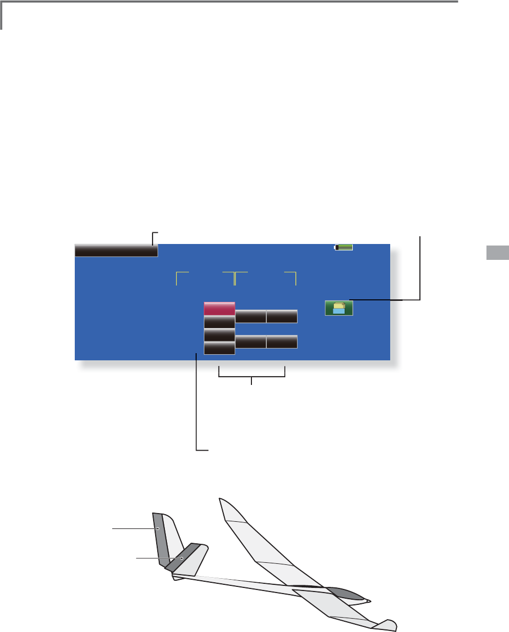
129
<Model Menu (Airplane/Glider Functions)>
85%
V-Tail Model 1
+50%
+50% +50%
+50% +50%
+50%
+50%
+50%
Group
Elevator
Elevator
Function
Rudder
Left Right
Function
Down
Up
Down
Up
(RUD2)
Rudder (ELE2)
Gr.
Condition 1
ŏ
5
H
W
X
UQW
R
0
RGH
O0
H
Q
X
9WDLO >&RUUHVSRQGLQ
J
PRGHOW\SH@$LUSODQH
J
OLGHU9WDL
O
This function let’s
y
ou ad
j
ust for left and ri
g
ht
ru
dd
er ang
l
e c
h
anges at e
l
evator an
d
ru
dd
e
r
R
SHUDW
L
RQRID9WD
LO
D
L
US
O
DQH
9WD
LO
L
VZ
K
HQVHUYRVDUHXVH
G
WRJHW
K
HUWR
c
ontro
l
ru
dd
er movement as E
l
evators. In a
ddi
t
i
on
t
o each rudder side moving up and down together,
e
ac
h
s
id
e moves
i
n oppos
i
te
di
rect
i
ons w
h
en
P
RY
L
Q
J
DV(
O
HYDWRUV2QD9WD
LO
W
KL
V
L
VD
O
VR
N
QRZQ
a
s a Ruddervator, as they can serve the same
p
u
rpose
.
ŏ
7RXFKWKH
>
9WDLO
@
EXWWRQLQWKH0RGHO0HQX
t
o call the setu
p
screen shown below
.
5XGGHUIXQFWLRQ
/
HIWDQGUL
J
KWWUDYHODG
M
XVWPHQWDW&+DQG&+
r
udder o
p
eratio
n
ŏ
*URXSVLQ
J
OHPRGHVZLWFKLQ
J
(
Gr./Sn
g
l
)
(
For more
i
nformat
i
on, see t
h
e
d
escr
i
pt
i
on
at the back of this manual.
)
(
Elevator
f
unct
i
on
)
8
SDQGGRZQWUDYHODG
M
XVWPHQWDW&+DQG&+
e
levator operat
i
o
n
ELEVATOR
(RUDDER 2)
RUDDER
(ELEVATOR 2)
V-TAIL
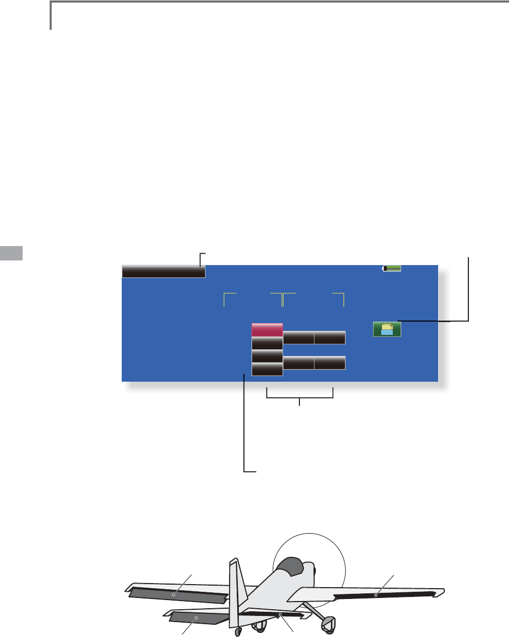
130 <Model Menu (Airplane/Glider Functions)>
85%
Ailevator Model 1
+100%
+0% +0%
+0% +0%
+100%
+100%
+100%
Group
Elevator
Elevator
Function
Aileron
Left Right
Function
Down
Up
Down
Up
(Aileron5)
Elevator2 (Aileron6)
Gr.
Condition 1
ŏ5
H
W
X
UQW
R
0
RGHO
0
H
Q
X
$LOHYDWRU >&RUUHVSRQGLQ
J
PRGHOW\SH@$LUSODQH
J
OLGHU97DL
O
(Effective onl
y
when 2 servos used at the elevators)
This function improves the operatin
g
performance of
th
e ro
ll
ax
i
s
b
y operat
i
ng t
h
e e
l
evators as a
il
erons.
A
ilevator is where each elevator in a standar
d
(
convent
i
ona
l)
or v-ta
il
moves
i
n
d
epen
d
ent
l
y,
lik
e
ail
erons on a w
i
n
g
. In a
ddi
t
i
on to eac
h
e
l
evator s
id
e
m
oving up and down together, each side moves in
o
ppos
i
te
di
rect
i
ons w
h
en mov
i
ng as an A
il
evator. On
D
9WD
LO
W
KL
V
L
VD
O
VR
N
QRZQDVD5X
GG
HUYDWRUDVW
K
H
\
c
an serve the same purpose. Typically, both Ailevato
r
a
n
d
a
il
erons are coup
l
e
d
toget
h
er to max
i
m
i
ze ro
ll
performance, espec
i
a
lly
on
l
ar
g
er w
i
n
g
span p
l
anes..
N
ote: Select A
i
levator as the Model Type at the Model
7
\SHVFUHHQ7K
L
VFKDQ
J
HVWKHRXWSXWFKDQQHO&KHF
N
t
h
e
F
u
n
c
t
io
n m
e
n
u.
ŏ7RXFKWKH
>
$,/
@
EXWWRQLQWKH0RGHO0HQXWR
call the setu
p
screen shown below
.
(
Aileron function
)
ŏ:KHQWKHHOHYDWRUVDUHXVHGDVDLOHURQV
DLOHURQWUDYHO
of the left and ri
g
ht elevators can be ad
j
usted
.
ŏ*URXSVLQ
J
OHPRGHVZLWFKLQ
J
(
Gr./Sn
g
l
)
(For more information, see the descri
p
tion
a
t the back of this manual.
)
(
Elevator
f
unct
i
on
)
ŏ7KHXSDQGGRZQUDWHRIWKHOHIWDQGULJKWHOHYDWRUV
when the elevator st
i
ck
i
s man
i
pulated can be
i
nd
i
v
i
dually ad
j
usted
.
ELEVATOR ELEVATOR 2
AILERON 1 AILERON 2
(AILERON 6)
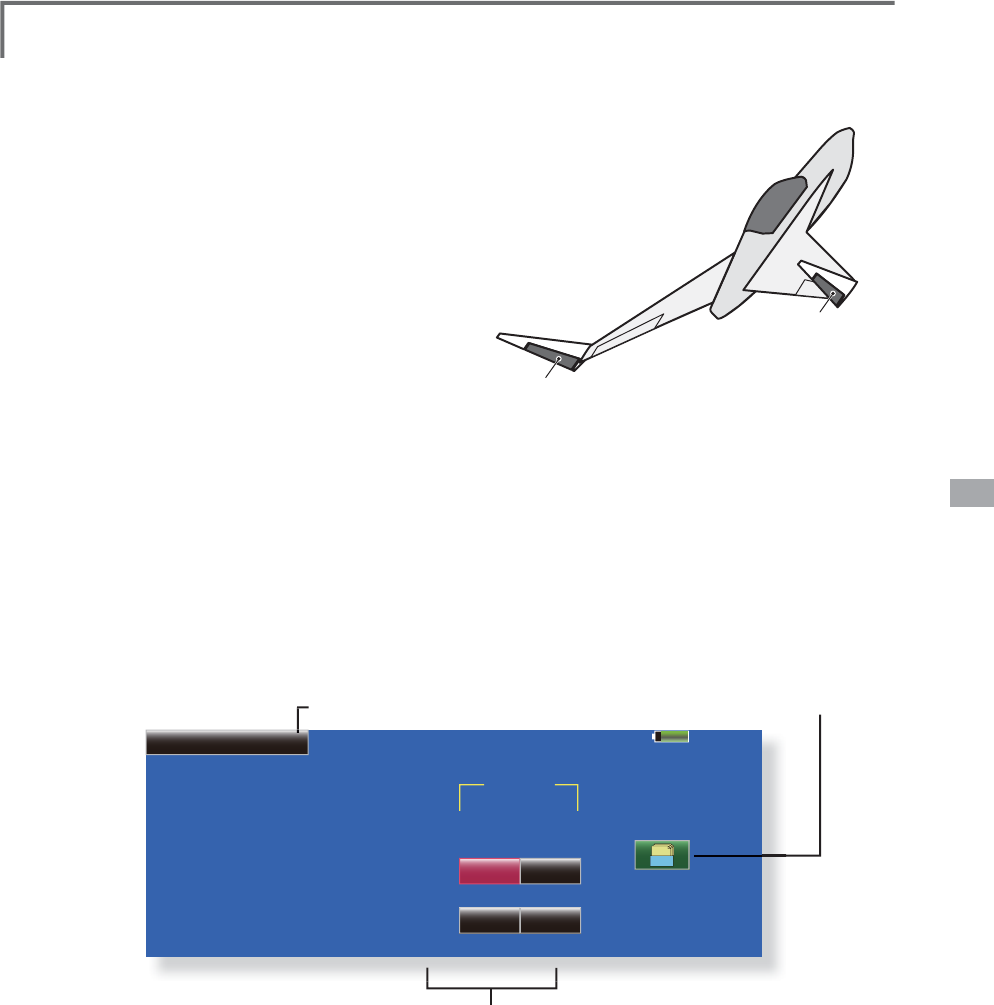
131
<Model Menu (Airplane/Glider Functions)>
RUDDER 1
Winglet
at Flying wing
( )
RUDDER 2
Winglet
at Flying wing
( )
85%
Winglet Model 1
+100% +0%
+0% +0%
Group
Rudder
Rudder
Rudder2
Left Right
Gr.
Condition 1
ŏ
5HWXUQWR0R
G
H
O
0HQX
:LQJOHW >&RUUHVSRQGLQ
J
PRGHOW\SH@$LUSODQH
J
OLGHUZLQ
J
OH
W
T
his function ad
j
usts the rubber left and ri
g
h
t
UX
GG
HUDQJ
O
HRIZ
L
QJ
O
HWVSHF
L¿
FDW
L
RQVIXVH
O
DJHV
Winglets are used to improve the efficiency o
f
a
i
rcraft
l
ower
i
ng t
h
e
li
ft-
i
n
d
uce
d
d
rag cause
d
b
y
wi
n
g
t
i
p vort
i
ces. T
h
e w
i
n
gl
et
i
s a vert
i
ca
l
or an
gl
e
d
extension at the tips of each wing.
Win
g
lets work b
y
increasin
g
the effective aspect
ratio wing without adding greatly to the structural
s
tress an
d
h
ence necessary we
i
g
h
t of
i
ts structure
-
an extension of win
g
span would also permit
l
owering of induced drag, though it would cause
p
aras
i
t
i
c
d
rag an
d
wou
ld
requ
i
re
b
oost
i
ng t
h
e
s
tren
g
th of the win
g
and hence its wei
g
ht - there
w
ould come a
p
oint at which no overall useful
s
av
i
ng wou
ld
b
e ma
d
e. A w
i
ng
l
et
h
e
l
ps to so
l
ve t
hi
s
by
effectivel
y
increasin
g
the aspect ratio without
adding to the span of the wing.
ŏ
7RXFKWKH>:
L
QJOHW@EXWWRQ
L
QWKH0RGHO
M
enu to ca
ll
t
h
e setup screen s
h
own
b
e
l
ow
.
5XGGHU
ŏ
7KHWUDYHODWUXGGHUVW
L
FNOH
I
WDQGU
L
JKWRSHUDW
L
RQFDQ
b
e
i
nd
i
v
i
dually set
.
ŏ
*URXSV
L
QJOHPRGHVZ
L
WFK
L
QJ
(
Gr./Sngl
)
(
For more information, see the descri
p
tion
at the back of this manual.)
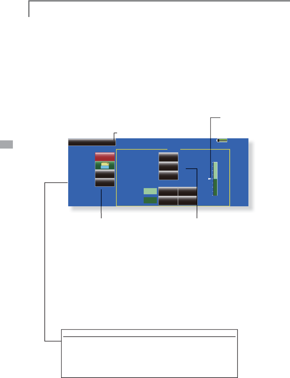
132 <Model Menu (Airplane/Glider Functions)>
85%
Model 1 Condition 1
Speed
0RWRU2í +0
Group
ON
Switch
INH
ACT/INH ACT/INH ON
OFF
One time mode
+0
Speed 1 to 2
Speed1
Speed2
INH
Gr.
Motor
INH
00
00
In Out
ŏ5
H
W
X
UQW
R
0
RGH
O0
H
Q
X
Motor
>
&RUUHVSRQGLQ
J
PRGHOW\SH@(3
J
OLGHU$LUSODQH
J
HQHUDO
This function lets
y
ou set the operation spee
d
wh
en t
h
e motor of a F5B or ot
h
er EP g
lid
er
i
s
starte
d
by
sw
i
tc
h
. T
h
e operat
i
on spee
d
can
b
e set
in 2 ran
g
es of slow speed fli
g
ht and hi
g
h spee
d
ÀL
J
K
W
6SHH
G
6SHH
G
7
KL
VIXQFW
L
RQFDQD
O
VR
E
H
o
perate
d
as a safet
y
funct
i
on
by
sett
i
n
g
2 sw
i
tc
h
es.
ŏ7KH,QV
L
GHDQG2XWV
L
GHRSHUDW
L
QJVSHHGVFDQ
b
e ad
j
usted
i
ndependently
i
n 2 ranges
(
Speed
1
/Speed 2).
ŏ7
K
H
E
RXQ
G
DU\
E
HWZHHQW
K
H
UDQJHVFDQ
E
HVHW
(From Speed 1 to Speed 2)
ŏ7KHVHWRSHUDWLRQVSHHGRSHUDWLRQFDQEH
a
ctivated at initial operation only.
(
1 time
operat
i
on
)
However, operat
i
on can be repeated
ŏ7RXFKWKH
>
0RWRU
@
EXWWRQLQWKH0RGHO0HQX
to call the setu
p
screen shown below
.
ŏ0RYHWKHFXUVRUE
\
VHW
V
ZLW
F
K
R
U95
E\VHWW
L
QJWKHVZ
L
WFKWR2))EH
I
RUHRSHUDW
L
RQ
L
V
À
Q
L
VKHG:KHQ
\
RXZDQWWRUHVHWW
L
PHR
S
HUDW
L
RQ
VHWWKH$&7EXWWRQWR
>
,1+
@
DQGWKHQUHVHWLWWR
>2
1
@
ŏ
7KHPRWRU&+LVFRQWUROOHGE\6:*>0RGH
@
6
:(>0RGH@
,QLWLDOVHWWLQ
J
:KHQFKDQ
J
LQ
J
W
KHVZLWFKRUVWLFNZKLFKFRQWUROVWKHPRWRUÀUVW
F
KDQ
J
H)XQFW
L
RQR
I
WKH/
L
QND
J
H0HQX
1RWH:KHQXVLQ
J
WKLVIXQFWLRQDOZD
\
VFKHFNLQLWLDO
R
S
HUDW
L
RQZ
L
WKWKH
S
UR
S
HOOHUUHPRYHG
1RWH7KHZDUQLQJPHVVDJHLVDSSHDUVZKHQWKHPL[LQJLV
RQVWDWXVDWWKHSRZHURQIRUVDIHW
\
ŏ2SHUDW
L
R
Q
7RXFKWKHEXWWRQDQGVHWWKHIXQFWLRQWR21
ŏ:KHQ\RXZDQWWRVHWWKH2QHW
L
PHPRGH
WRXFKWKHEXWWRQDQGVHWWKHPRGHWR
>
21
@
ŏ6SHHGWR
The Speed 1 and Speed 2 reg
i
on boundary
can be changed
,
ŏ2SHUDW
L
RQVSHHGDG
M
XVWPHQ
W
The speed when Speed 1 and Speed 2 are
21,QDQG2))2XWFDQEHDGMXVWHG
ŏ2SHUDW
L
R
Q
Touch the button and set the
f
unct
i
on to
21
ŏ*URXSV
L
QJOHPRGHVZ
L
WFK
L
QJ
*U6QJO
(For more information, see the description
at the back o
f
th
i
s manual.
)
ŏ6Z
L
WF
K
A switch that turns the function itself
2
1
2
))FDQ
E
HVH
O
HFWH
G
ŏ0RWRURI
I
[Yes] and [No] are displayed by touching
WKH0RWRU2IIEXWWRQZKHQ>6:*0RGH@
>6:(0RGH@LVLQWKHPRWRU2))SRVLWLRQ
:KHQ><HV@
L
VWRXFKHGWKHG
L
UHFW
L
RQR
I
the motor sw
i
tch
i
s memor
i
zed. The screen
JUDSKGLVSOD\21GLUHFWLRQDOVRFKDQJHV
N
otes
ŏ)LUVWGHFLGHWKHPRWRU2))
S
RLQWDQGWKHQVHWWKHV
S
HHG:KHQ
\
RXZDQWWR
UHVHWWKHPRWRU2))SRLQWDOVRUHVHWWKHVSHHG
ŏ:HUHFRPPHQGWKDW0RWRU2))EHVHWLQFRPELQDWLRQZLWK)
6
ŏ6HWWKHEDV
L
FRSHUDW
L
RQG
L
UHFW
L
RQZ
L
WKWKH5HYHUVH
I
XQFW
L
RQWRPDWFKWKH
a
mp used.
ŏ$OZD\VVHWWKH0RWRU2))SRV
L
W
L
RQ
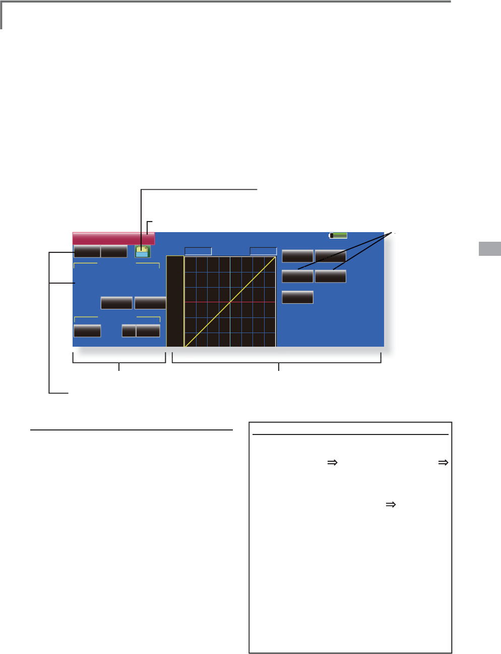
133
<Model Menu (Airplane/Glider Functions)>
85%
RUD to ELE
INH OFF POS +0.0%
( +0%)
Linear Separate
+100.0% +100.0%
Model 1 Condition 1
Gr.
+150
+100
+50
+0
-50
-
150
-100
RATE
Rate A
+0.0%
2íVHW
Rate B
+0.0%
'LVSOD\
Single
Link
INH
NULL +0%
0HPRU\
0HPRU\Recall
Fine Tuning
ŏ5
H
W
X
UQW
R
0
RGH
O0
H
Q
X
RUD to ELE >&RUUHVSRQGLQ
J
PRGHOW\SH@$LUSODQH
J
HQHUD
O
T
his function is used when
y
ou want to mix
e
l
evator operat
i
on w
i
t
h
ru
dd
er operat
i
on. It
i
s use
d
to correct un
d
es
i
ra
bl
e ten
d
enc
i
es w
h
en ru
dd
er
i
s
applied in roll maneuvers, knife ed
g
e, etc. of stunt
pl
anes.
ŏ$PL[LQ
J
FXUYHFDQEHVHW
ŏ0
L
[
L
Q
J
GXU
L
Q
J
ÁLJ
KWFDQEHWXUQHG212))E\
VHWW
L
Q
J
DVZ
L
WFK
$OZD\V21DW18//VHWW
L
Q
J
ŏ7K
H
D
P
RX
QW
RI
FR
UU
HF
W
LR
QU
XGGH
U
FD
Q
EH
memor
i
zed by us
i
ng the Memory
f
unct
i
on. Th
i
s
i
s
ŏ7RXFKWKH
>
58'WR(/(
@
EXWWRQLQWKH0RGHO0HQXWR
call the setu
p
screen shown below
.
ŏ0L[LQJFXUYHVHWWLQJ
(
For a
d
escr
i
pt
i
on of t
h
e curve sett
i
n
g
met
h
o
d
, see
t
h
e
d
escr
i
pt
i
on at t
h
e
b
ac
k
of t
hi
s manua
l
.
)
ŏ)LQHWXQLQJ95VHWWLQJ
ŏ:KHQ
>
,1+
@
LVWRXFKHGWKHPHPRU
\
items are dis
p
la
y
ed
.
FRQYHQ
L
HQWDWP
L
[
L
QJFXUYHVHWW
L
QJ:KHQPHPRU\
operat
i
on
(
sw
i
tch operat
i
on
)
i
s per
f
ormed w
i
th
correction rudder a
pp
lied in the Memor
y
Mode,
the stick
p
osition at that time is dis
p
la
y
ed on the
PL[LQJFXUYH7KHSRLQWLVDXWRPDWLFDOO\UHÁHFWHG
LQWKHFXUYH
:KHQWKH0HPRU\IXQFWLRQLVXVHG
/LQHLVDXWRPDWLFDOO\VHOHFWHGDVWKHFXUYHW\SH
ŏ/
L
QNFDQEHVHW/
L
QNVWK
L
VP
L
[
L
Q
J
WRRWKHUP
L
[
L
Q
J
V
ŏ7KHP
L
[
L
Q
J
UDWHFDQEH
À
QHWXQHGE\VHWW
L
Q
J
D95
(
F
i
ne tun
i
ng
)
ŏ2YHUDOO
a
d
j
ustmen
t
E\
5DWH$
D
Q
G
5
D
W
H
%
ŏ
*URXSVLQ
J
OHPRGHVZLWFKLQ
J
*U6Q
J
O
(
For more
i
nformat
i
on, see t
h
e
d
escr
ip
t
i
on at t
h
e
b
ac
k
of
thi
s manua
l
.
)
6
HWW
L
QJPHWKRG
ŏ7RXFKWKH,1+EXWWRQ
DQGVHWWKH
I
XQFW
L
RQWR
$&7
21
ŏ:KHQVHWWLQJDVZLWFKWRXFKWKH18//EXWWRQ
to call the <Switch> screen, and then select the
VZLWFKDQGVHWLWV21GLUHFWLRQ$OZD\V21DW
18//VHWWLQ
J
(
For a description of the switch settin
g
method,
see the descr
i
pt
i
on at the back o
f
th
i
s manual.
)
ŏ:KHQVHWW
L
Q
J
D95WRXFKWKH)
L
QH7XQ
L
Q
J
18//
button to call the <Sw
i
tch> screen
,
and then
VHOHFWWKH957KH
À
QHWXQ
L
QJUDWHDQGDG
M
XVWPHQW
di
r
ec
t
io
n
ca
n
be
se
t
.
7KH95R
S
HUDWLRQPRGHFDQDOVREHVHW
)RUDGHVFULSWLRQRIWKHÀQHWXQLQJ95VHWWLQJ
method, see the description at the back of this
manual.
)
ŏ7KHFXUYHG
L
VSOD\PRGHFDQEHFKDQ
J
HG
6
L
Q
J
OH'
L
VSOD\VWKHP
L
[
L
Q
J
FXUYHRQO
\
)
L
QH7XQ
L
QJ'
L
VSOD\VWKH
À
QHWXQ
L
QJUDWHR
I
WKH
À
QHWXQ
L
QJ9
5
$OO&RQG'
L
VSOD\VWKHP
L
[
L
QJFXUYHR
I
DOOWKH
FRQGLWLRQV:KHQFRQGLWLRQVDUHVHW
ŏ:KHQVHWWLQJ/LQNWRXFKWKH/LQNEXWWRQDQGVHWLW
WR
2
1
0HPRU\
I
XQFW
L
RQXVDJHPHWKR
G
([DPSOH
8V
L
QJWKHPHPRU\
I
XQFW
L
RQZ
L
WKDQ)$
a
i
rplane
(
kn
if
e edge correct
i
on
)
*
W
h
en ca
ll
sw
i
tc
h
[SW-A] and memory switc
h
[
SW-H
]
were set
[
Memor
y
function o
p
eration
]
1. Memory function mode: [Manual] [Memory]
:KHQWKHPHPRU\VZ
L
WFK
6:+
L
VVHWWR21
wh
i
le per
f
orm
i
n
g
elevator correct
i
on when
rudder was appl
i
ed at kn
if
e ed
g
e, the po
i
nt
p
os
i
t
i
on at that t
i
me
i
s memor
i
zed. Memor
i
zat
i
on
i
s per
f
ormed wh
i
le chang
i
ng the le
f
t and r
i
ght
s
tick
p
ositions.
7RUHFDOOWKHPHPRUL]HG
S
RVLWLRQVVHW
>
6:$
@
WR21
7
KHPHPRUL]HGFRUUHFWLRQUDWHLVUHÁHFWHGRQWKH
curve, and operation is simultaneously set.
1RWH:
K
HQPHPRU
L
]H
G
IURPPDQXD
O
E
HIRUH
ÀL
J
K
W
E
HVXUHW
K
DW
th
e memory SW
i
s not acc
id
enta
ll
y set to ON an
d
i
ncorrec
t
mi
x
i
ng sett
i
ng
i
s not app
li
e
d
w
h
en tax
ii
ng, start
i
ng t
h
e eng
i
ne,
etc.
A
B
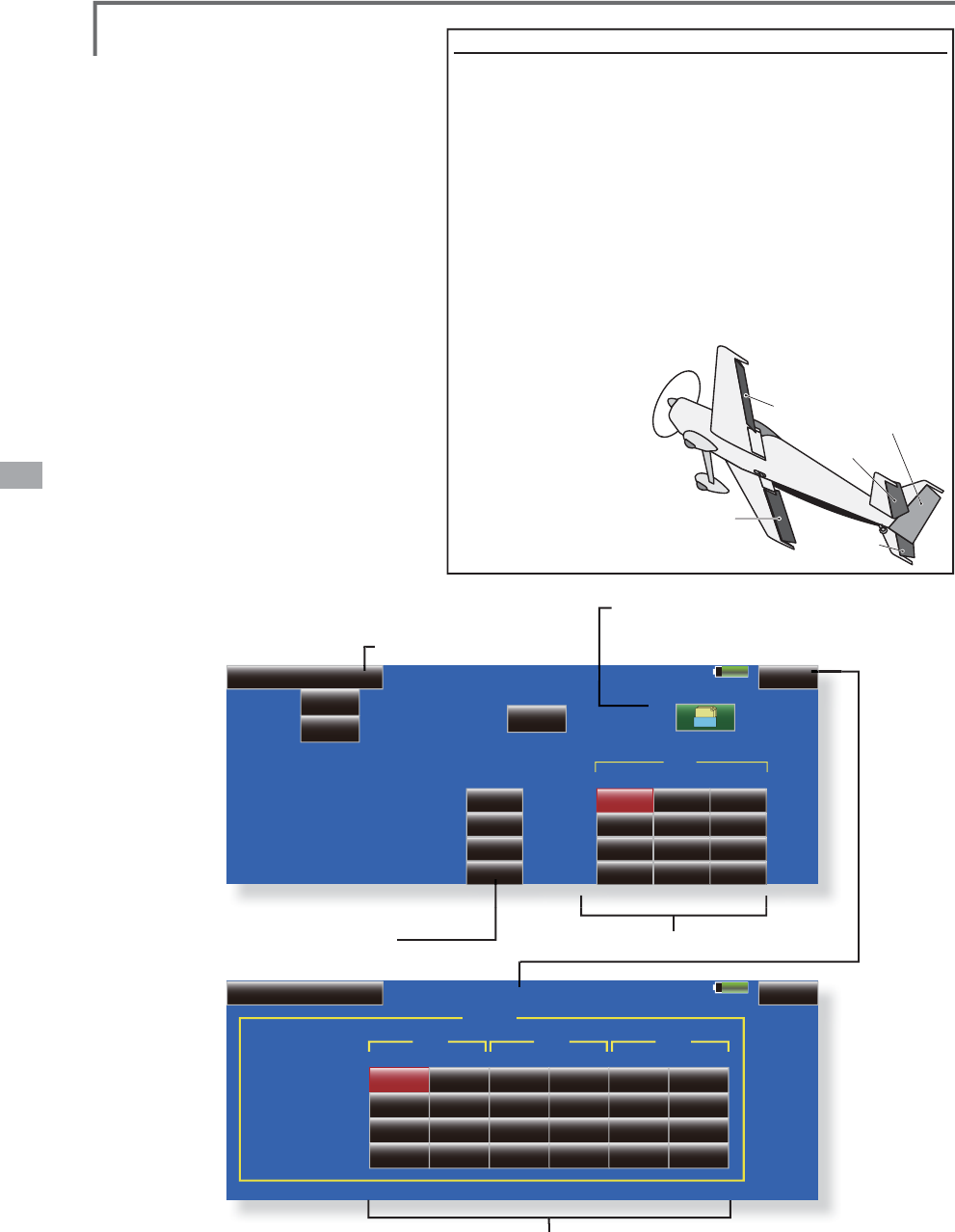
134 <Model Menu (Airplane/Glider Functions)>
85%
+100%
RUDELE
1/2
Model 1 Condition 1
Snap Roll
-100%
+100%
-100%
OFF
Switch
OFF
OFF
OFF
OFF
ACT
OFF
OFF
OFF
Right / UP
Right / Down
Left / UP
Left / Down
+100%
AIL
+100%
-100%
-100%
+100%
-100%
-100%
+100%
Rate
Group Gr.
ON
Safety SW
Master
Mode
OFF
Master SW
85% 2/2
Model 1 Condition 1
Snap Roll
Right / UP
Right / Down
Left / UP
Left / Down
AIL ELE RUD
IN Out
00
00
00
00
IN Out
00
00
00
00
IN Out
00
00
00
00
Speed
Snap Roll >&RUUHVSRQGLQ
J
PRGHOW\SH@$LUSODQH
J
HQHUD
O
This
f
u
n
c
t
io
n
selec
t
s
t
he
swi
t
ch
an
d
r
ate a
dj
ustment of eac
h
ru
dd
er,
(
a
il
erons,
elevators, or fla
p
s) when a sna
p
roll is
p
erforme
d
.
ŏ)RXUVQDSUROOGLUHFWLRQVFDQEHVHW
5L
J
KW
up, r
ig
ht/down, le
f
t/up, le
f
t/down
)
ŏ2SHUDW
L
RQPRGH:KHQ>0DVWHU@PRGH
L
VVHOHFWHGWKH6QDS5ROO
I
XQFW
L
RQ
L
V
WXUQHG212))E
\
PDVWHUVZ
L
WFK
L
QWKH
s
t
a
t
e
in whi
c
h th
e
d
ir
ec
ti
o
n
s
wit
c
h w
as
s
witched to the direction in which
y
ou
ZDQWWRVQDSUROO:KHQ>6LQJOH@PRGHLV
s
elected, snap roll in each direction can
b
e executed by means of independent
s
w
i
tches.
ŏ$VD
I
HW\VZ
L
WFKFDQEHVHW$VD
s
a
f
ety measure, the sw
i
tch can be
s
et so that sna
p
roll
i
s not executed
when, for instance, the landing gear
i
s lowered, even if the switch is turned
on accidentall
y
. The sna
p
roll switch is
a
ctivated only when the safety switch is
2
1
ŏ7KHRSHUDW
L
RQVSHHGR
I
WKHD
L
OHURQ
HOHYDWRUDQG
Á
DSVHUYRVFDQEHDG
M
XVWHG
I
RUHDFKVQDSUROOG
L
UHFW
L
RQ
,QV
L
GH2XW
si
de
)
(
Page 2/2
)
([DPSOH
6
HWW
L
Q
J
H[DPSOH
I
RU)$
ŏ0RGH
>
0DVWHU
@
ŏ6DIHW\6:>6:*@
6DIHW\PHDVXUH
ŏ0DVWHU6:>6:+@
0DLQVZLWFKIRUH[HFXWLQ
J
VQDSUROO
ŏ'LU
HF
WL
R
Q
V
ZLW
F
K
HV
*
The snap roll up side left and ri
g
ht and down side left and ri
g
ht direction switches
are selected here.
5
LJKW8S2))>6:'@5LJKW'RZQ2))>6:'@/HIW8S2))
>6
:$
@
/H
I
W'RZQ2))>6:$
@
ŏ6SHHGDG
M
XVWPHQW
6FUHHQ
The o
p
eration s
p
eed of each control surface when
WKHVQDSVZLWFKLV21FDQEHFKDQ
J
HGDQGVQDSUROO
executed b
y
stick while there is switch o
p
eration can be
p
erformed
.
ŏ7RXFKWKH
>
6QD
S
5ROO
@
EXWWRQ
in th
e
M
ode
l M
e
n
u
to call the setu
p
sc
r
ee
n
s
h
o
wn
be
l
o
w
.
ŏ5
H
W
X
UQW
R
0
RGH
O0
H
Q
X
ŏ
&XUYHG
L
VSOD\PRGHVZ
L
WFK
L
QJ
(
S
i
ng
l
e
/
F
i
ne tun
i
ng
/
A
ll
Con
d
.
)
ŏ*URXSV
L
QJOHPRGHVZ
L
WFK
L
QJ
*U6QJO
(
For more
i
nformat
i
on, see t
h
e
d
escr
i
pt
i
on at t
h
e
b
ac
k
of t
hi
s manua
l
.
)
ŏ5DWHDGMXVWPHQWRIHDFKUXGGHU
ŏ'LU
HF
WL
R
Q
V
ZLW
F
K
HV
ŏ$GMXVWPHQWRIWKHVHUYRVSHHGRIHDFKUXGGHU
(
For a
d
escr
i
pt
i
on of t
h
e sett
i
ng met
h
o
d
, see t
h
e
d
escr
i
pt
i
on at t
h
e
b
ac
k
of t
hi
s manua
l
.
)
AIL1
AIL2
ELEVATOR
ELEVATOR 2
RUDDER
(at AILEVATOR)
Co
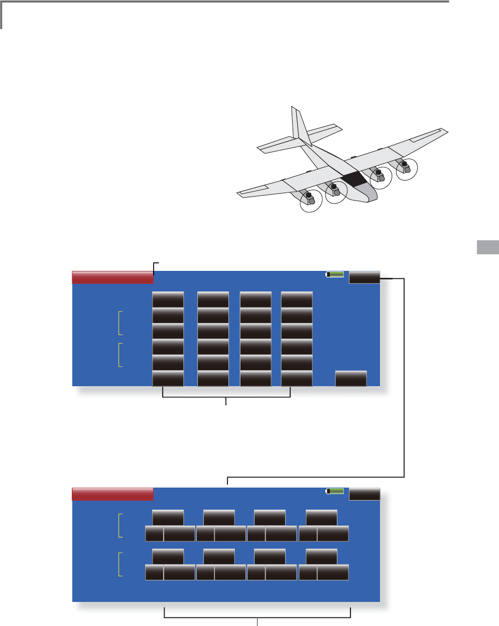
135
<Model Menu (Airplane/Glider Functions)>
85% 1/2
Model 1 Condition 1
Multi Engine
ACT / INH
ACT
Posi.
Throttle Cut
Throttle Hold
Idole Down
THR
INH
17%
ACT
Rate
INH
INH
INH
17%
THR2
INH
17%
INH
INH
INH
17%
THR3
INH
17%
INH
INH
INH
17%
THR4
INH
Hold Pos.
17%
17%
INH
INH
INH
17%
85% 2/2
Model 1 Condition 1
Multi Engine
Control
( +0% )
Rate
High Trim
THR
0%+
INH
Control
( +0% )
Rate
Idle Trim
0%+
INH
THR2
( +0% )
0%+
INH
( +0% )
0%+
INH
( +0% )
0%+
INH
( +0% )
0%+
INH
( +0% )
0%+
INH
( +0% )
0%+
INH
THR3 THR4
0XOWL(QJLQH
>
&RUUHVSRQGLQ
J
PRGHOW\SH@$LUSODQH
J
HQHUDO
Thi
s funct
i
on
l
ets you a
dj
ust t
h
e t
h
rott
l
e w
h
en
usin
g
a multi en
g
ine airplane with up to 4 en
g
ines.
T
he Throttle Cut function
,
Idle Down function
,
Th
rott
l
e Ho
ld
funct
i
on, H
igh
Tr
i
m, an
d
I
dl
e Tr
i
m
can be ad
j
usted b
y
throttle channel (THR, THR2,
7
+57+5
*
In
i
t
i
a
l
sett
i
n
g
ass
ig
ns on
ly
one t
h
rott
l
e c
h
anne
l
(
THR
)
.
W
h
en us
i
n
g
t
hi
s funct
i
on, t
h
e num
b
er of t
h
rott
l
e c
h
anne
l
s
must
b
e ass
i
gne
d
b
efore
h
an
d
at t
h
e Funct
i
on menu of t
h
e
Li
n
k
age Menu.
ŏ7KHWKURWWOHFXW
S
RV
L
W
L
RQFDQEHVHW
I
RUHDFK
throttle channel. Throttle cut o
p
eration is linked to
WKHVZLWFKVHWZLWKWKH7KURWWOH&XWIXQFWLRQRIWKH
/LQNDJH0HQX
*The throttle cut
p
osition set at this screen is effective.
ŏ7K
H
WKU
R
WWO
H
GR
ZQ
R
II
VH
WU
D
W
H
FD
Q
EH
VH
WI
R
U
HDF
K
WKURWWOHFKDQQHO,GOHGRZQR
S
HUDWLRQLVOLQNHGWR
WKHVZLWFKVHWZLWKWKH,GOH'RZQIXQFWLRQRIWKH
/LQND
J
H0HQX
ŏ5
H
W
X
UQW
R
0
RGH
O0
H
Q
X
ŏ
7RXFKWKH>0XOWL(Q
J
LQH@EXWWRQLQWKH0RGHO
M
enu to call the setu
p
screen shown below
.
*
T
h
e num
b
er of en
gi
nes
(
1~4
)
ass
ig
ne
d
by
Funct
i
on
menu
i
n t
h
e L
i
n
k
a
g
e Menu setup screen
i
s
di
sp
l
a
y
e
d
.
*
The idle down offset rate set at this screen is effective.
ŏ
2SHUDWLRQFDQEHÀ[HGDWWKHHQ
J
LQHVSHHG
(
carburetor open
i
n
g
an
g
le
)
f
or each throttle
c
hannel w
i
th the Hold Pos
i
t
i
on
f
unct
i
on. The hold
p
os
i
t
i
on can be chan
g
ed.
ŏ
+
L
JKV
L
GHWU
L
PDQG
L
GOHWU
L
PFDQEHVHW
I
RUHDFK
F
KDQQHO2SHUDW
L
RQDFWVDVK
L
JKWU
L
PRU
L
GOHWU
L
P
based
o
n t
he
ce
nt
e
r
.
ŏ7KURWWOHFXWSRVLWLRQVHWWLQJ
IRUHDFK
e
n
g
ine
)
ŏ,GOHGRZQRIIVHWUDWHVHWWLQJ
IRUHDFK
e
ngine
)
ŏ7KURWWOHKROGSRVLWLRQVHWWLQ
J
ŏ+L
J
K7ULPVHWWLQ
J
IRUHDFKHQ
J
LQH
ŏ,GOH7ULPVHWWLQ
J
IRUHDFKHQ
J
LQH
THR1
THR2
THR3
THR4
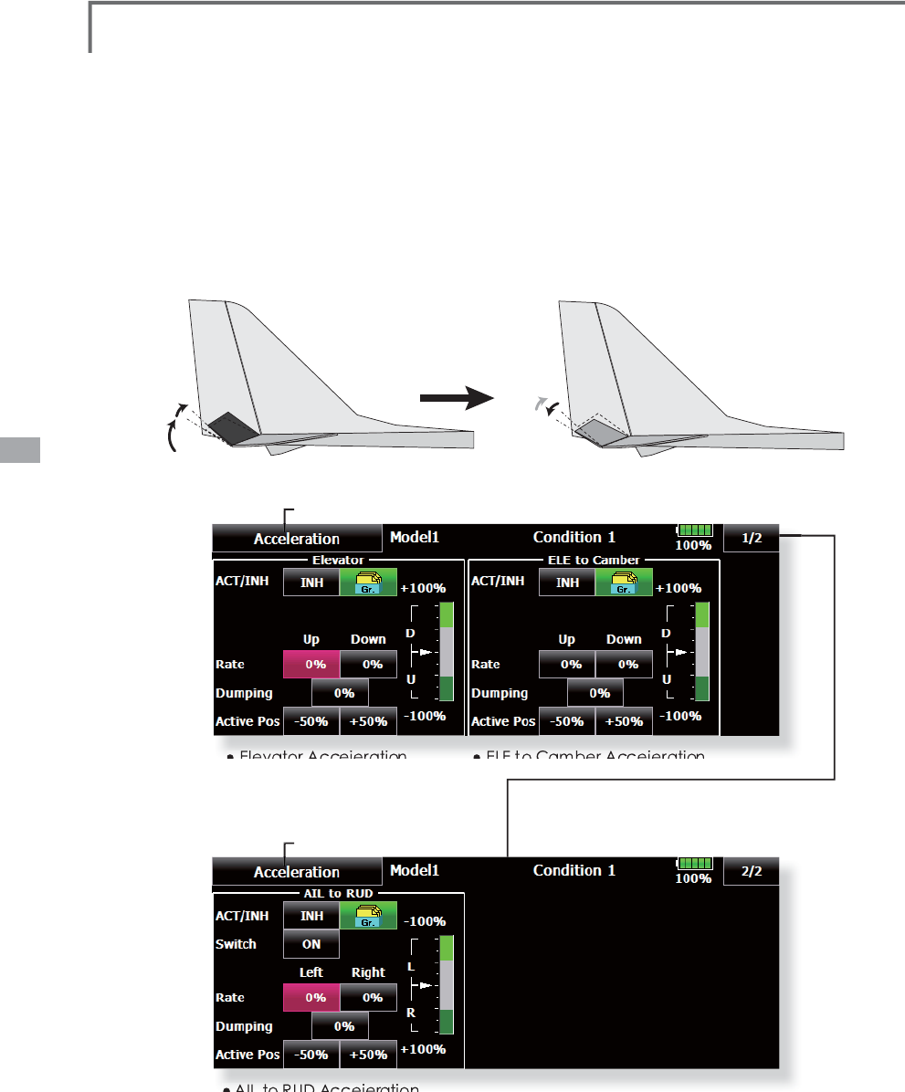
136 <Model Menu (Airplane/Glider Functions)>
Accelerration >&RUUHVSRQG
L
QJPRGHOW\SH@(3JO
L
GHUJO
L
GH
U
Acceleration settin
g
can be performed at elevator,
ELE to
C
AMBER an
d
AILER
O
N to R
U
DDER.
(
G
lid
er an
d
EP
glid
er on
ly)
ŏ7KLVVHWWLQJLVGLYLGHGLQWRHOHYDWRUVHWWLQJ
andcamber setting. The setting method is the same.
ŏ&DPEHUVHWWLQ
J
VHWVWKHDFFHOHUDWLRQIXQFWLRQIRU(/(
WR&$0%(5PL[LQ
J
6HWWLQ
J
LVQRWSHUIRUPHGZKHQ
(/(WR&$0%(5P
L
[
L
Q
J
L
V,1+
ŏ7KHDFFHOHUDW
L
RQ
I
XQFW
L
RQFDQEHVHW
I
RUERWKWKH
8
3
V
L
GHDQG'2:1V
L
GH
ŏ)XQFWLRQ212))VZLWFKVHWWLQJLV
S
HUIRUPHGIRU$,/(521WR58''(5VHWWLQJRQO\
ŏ$,/(521WR58''(5VHWWLQ
J
LVDFFHOHUDWLR
Q
IXQFWLRQVHWWLQ
J
IRUDLOHURQWRUXGGHUPL[LQ
J
,WLVQRW
S
HU
I
RUPHGZKHQ$,/(521WR58''(5P
L
[
L
Q
J
L
V,1+
ŏ5
H
W
X
UQW
R
0
RGH
O0
H
Q
X
ŏ5HWXUQWR0R
G
H
O
0HQ
X
ŏ
(OHYDWRU
$FFHLHUDWLRQ
ŏ
(/(
WR
&DPEHU
$FFHLHUDWLRQ
ŏ
$,/
WR
58'
$FFHLHUDWLRQ
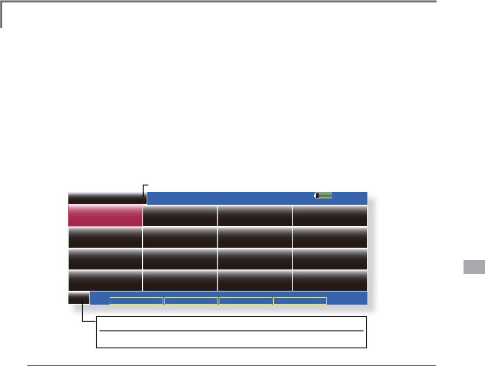
137
<Model Menu (Helicopter Functions)>
MODEL MENU (HELICOPTER)
System Menu
--Condition Hold
Linkage Menu Model Menu Cond.Hold
Model 1 Normal 85%
Model Menu
INH
Condition Select AFR ( D/R ) Prog. Mixes
THR Curve Acceleration
Throttle Mix PIT to RUD
Gyro
PIT Curve
Servo Monitor
Swash Mix
Fuel Mixture
Pit to Needle
1/1
Throttle Hold
Governor THR Limiter
This section contains information on the
c
omman
d
s t
h
at app
l
y to
h
e
li
copters on
l
y. Fo
r
i
nstruct
i
ons on A
i
rp
l
anes an
d
Sa
il
p
l
anes, refe
r
t
o the sections pertainin
g
to those aircraft. Each
o
f t
h
ese funct
i
ons can
b
e set
i
n
d
epen
d
ent
l
y fo
r
GL
IIHUHQW
ÀLJK
WFRQ
GL
W
L
RQV7R
J
HWWRW
K
HVHVHWW
L
Q
J
V
t
ouch the desired function button to be entered.
U
se t
h
e Mo
d
e
l
T
y
pe funct
i
on
i
n t
h
e L
i
n
k
a
g
e
Menu to select the swash type matched to the
fusela
g
e beforehand. If
y
ou later chan
g
e model
types, a
ll
sett
i
ngs w
ill
b
e
l
ost.
Also, add flight conditions at the Condition
S
e
l
ect screen
b
efore sett
i
ng t
h
e mo
d
e
l
d
ata at eac
h
funct
i
on.
(
Up to 8 con
di
t
i
ons can
b
e use
d)
Th
e AFR funct
i
on
,
fue
l
m
i
xture an
d
ot
h
e
r
functions common to all model t
y
pes, are described
in a se
p
arate section.
ŏ
5
H
W
X
UQW
R
+
R
P
H
VF
U
HH
Q
ŏ
7RXFKWKH0RGHO0HQXEXWWRQR
I
WKH+RPHVFUHHQWR
F
DOOWKHPHQXVKRZQEHORZ7RXFKWKHEXWWRQR
I
WKH
I
XQFW
L
RQ\RXZDQWWRVHWWRFDOOWKHVHWXSVFUHHQ
Model Menu functions (helico
p
ter) list
C
ondition Hold function
ON/O
FF button
)RUDGHWD
L
OHGGHVFU
L
SW
L
RQVHHS
&RQG
L
W
L
RQ+ROG
I
XQFW
L
RQ
PIT
C
urve:$
GM
XVWVUHVSRQVH
L
Q
GL
IIHUHQW
ÀL
J
K
WFRQ
GL
W
L
RQ
V
THR
C
urve: Throttle curve and hovering trim adjustment
Acceleration: Counteracts tor
q
ue due to sudden throttle and
p
itch commands
Th
rott
l
e
H
o
ld
:Moves the throttle to idle durin
g
autorotation
S
wash M
i
x: Compensates for eac
h
contro
l
response
Thr
o
ttl
e
Mix
:
Compensates for power
l
oss w
h
en cyc
li
c app
li
e
d
Pit to
N
eedle: $GMXVWVUHVSRQVHFXUYHLQGLIIHUHQWÀLJKWFRQGLWLRQV
Pit to RUD: Handles torque chan
g
es from pitch an
g
le inputs
F
uel M
i
xture: Comman
d
s a secon
d
servo to a
dj
ust t
h
e fue
l
m
i
xture at t
h
e car
b
uretor
G
yro: Use
d
to sw
i
tc
h
Futa
b
a GY ser
i
es gyro sens
i
t
i
v
i
ty
G
overnor: Used to switch RPM of the helico
p
ter’s head
Throttle Limiter: Limits the hi
g
h ran
g
e of the throttle movement b
y
an
y
slider or trimmer
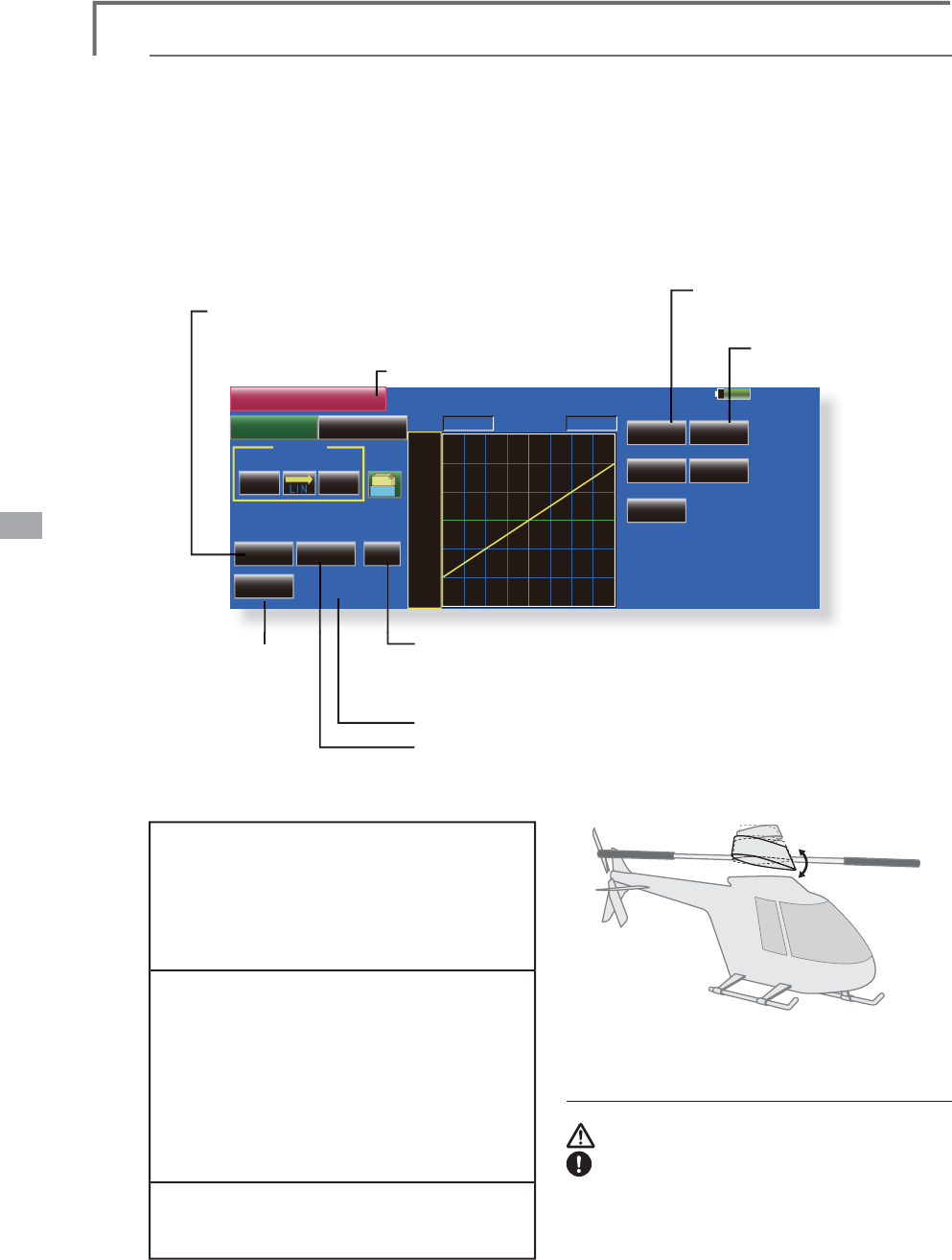
138 <Model Menu (Helicopter Functions)>
85%
POS -100%
Linear Separate
+100.0% +100.0%
Model 1 Normal
Gr.
+150
+100
+50
+0
-50
-150
-100
RATE
Rate A
Single
Tri m
Angle %
Display Unit
+0.0%
2íVHW
Rate B
-100%
IN
ThrottlePitch
0 0
PIT Curve
Speed
OUT
PIT Curve/Pitch Trim
P
IT
C
urve
T
his function adjusts the pitch operation curve
IRUHDF
K
ÀLJK
WFRQ
GL
W
L
RQIRUW
K
HRSW
L
PD
O
ÀLJK
WVWDWH
relative to movement of the throttle stick.
T
he pitch curve can be freely selected from linear operation
curve to smooth curve, and ad
j
usted to match the curve
y
ou want b
y
means of the T18MZ’s powerful Curve Edit
Funct
i
on
(
6 t
y
pes of curves can
b
e se
l
ecte
d)
. Up to 17 po
i
nts
can
b
e set for
li
near or curve t
y
pes. However, w
h
en us
i
n
g
W
KH
S
RLQWVRU
S
RLQWVV
S
HFL¿HGWRFUHDWHDFXUYHDVLP
S
OH
a
nd smooth curve can be created by selecting the curve type
a
nd reducin
g
the number of input points to 3 or 5, and then
e
nterin
g
the specified value at the correspondin
g
points
th
at
y
ou create
d
.a curve, a s
i
mp
l
e an
d
smoot
h
curve can
b
e
c
reate
d
by
se
l
ect
i
n
g
t
h
e curve t
y
pe an
d
re
d
uc
i
n
g
t
h
e num
b
er
o
f
i
nput po
i
nts to 3 or 5, an
d
t
h
en enter
i
ng t
h
e spec
i
f
i
e
d
v
a
l
ue at t
h
e correspon
di
ng po
i
nts t
h
at you create
d
.
ŏ5HWXUQWR0R
G
H
O
0HQ
X
ŏ
7RXFKWKH
>
3,7&XUYH
@
EXWWRQLQWKH0RGHO0HQXWR
F
DOOWKHVHWXSVFUHHQVKRZQEHORZ
ŏ
7KHUHDUHW
\S
HVRIGLV
S
OD
\
7KHFXUYHRIDOOWKH
F
RQGLWLRQVRUWKHSLWFKDQGWKURWWOHFXUYHVFDQEH
G
LV
S
OD
\
HGRQRQHVFUHHQ
ŏ
/LQHDUW\SHLVSRLQWVEXWIR
U
V
LP
S
OHXVHa
S
RLQWVDUH
V
XIÀFLHQW
ŏ
1RUPDOO
\
XVH6H
S
DUDWH
ŏ
7ULP
FD
Q
EH
XVHG
D
VKRYHULQJSLWFK
D
QGSLWFKWULP
7
KHKLJKDQGORZ
V
LGHSLWFKFDQ
EH
ÀQ
H
W
X
Q
HG
ŏ
8QLWVFDQEHVHOHFWHGIURP>@DQG>'HJ@:KHQ>'HJ@LV
V
HOHFWHGWKHURWRUSLWFKDQ
J
OHLVGLVSOD\HGDQGEHFRPHVWKH
V
HWWLQJVWDQGDUG:KHQ>'HJ@ZDVVHOHFWHGWKHKLJKFHQWHU
D
QGORZSLWFKDQ
J
OHVDUHHQWHUG
ŏ
&DQEHFRSLHGWRWKHSLWFKWULPDG
M
XVWPHQWSRVLWLRQ
ŏ
:KHQWKH>$QJOH@EXWWRQLVWRXFKHGWKHSLWFKDQJOHLQSXW
V
FUHHQLVGLVSOD\HG,QSXWWKHPD[LPXPSLWFKFHQWHUDQGORZ
S
LWFK
Normal curve adjustment
ŏ)RUQRUPDOFXUYHXVXDOO\XVH>/
L
QH@W\SHDQG
FUHDWHDEDV
L
FS
L
WFKFXUYHFHQWHUHGDERXW
KRYHU
L
QJ8VHWK
L
V
I
XQFW
L
RQWRJHWKHUZ
L
WKWKH
7+5&XUYH
1RUPDO
I
XQFW
L
RQDQGDG
M
XVWWKH
FXUYHVRWKDWXSGRZQFRQWURO
L
VEHVWDWD
FRQVWDQWHQJ
L
QHVSHHG
Idle up curve adjustment
ŏ)RUWKHK
L
JKV
L
GHS
L
WFKFXUYHVHWWKH
PD[
L
PXPS
L
WFKZK
L
FKGRHVQRWDSSO\D
ORDGWRWKHHQJ
L
QH)RUWKHORZV
L
GHS
L
WFK
FXUYHFUHDWHFXUYHVPDWF
K
H
G
WR
O
RRSUR
OO
'DQGRWKHUSXUSRVHVDQGXVHWKH
L
GOHXS
FXUYHVDFFRUG
L
QJWRWKHSHU
I
RUPDQFH
1RWH:KHQWKHFXUYHW\SHLVFKDQJHGWKHGDWDLV
UHVHW
Throttle hold curve ad
j
ustment
ŏ7KHWKURWWOHKROGFXUYHLVXVHGZKHQ
H[HFXWLQJDXWRURWDWLRQGLYHV
Operat
i
on precaut
i
ons
WARNING
:KHQDFWXDOO\VWDUWLQ
J
WKHHQ
J
LQHDQG
IO\LQ
J
DOZD\VVHWWKHLGOHXSFRQGLWLRQ
VZLWFKWR>2))@DQGVWDUWWKHHQ
J
LQHLQWKH
LGOLQ
J
VWDWH
85
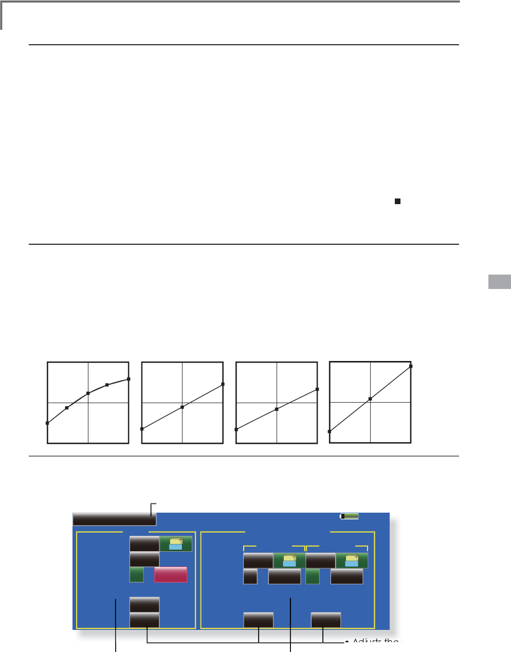
139
<Model Menu (Helicopter Functions)>
85%
Model 1
Hover
Pitch Trim
INHACT/INH
ACT/INH
Mode
Rate Rate
Range
Control
( +0%)
Low Pitch
Normal
Gr.
INH Gr.
- 30%
( +0%)
+0%
INH Gr.
( +0%)
-0%
100%
NULL Control NULL NULL
Low Pitch / High Pitch
CTRM
High Pitch
Normal Curve Idle-up 1 Curve Idle-up 2 Curve Hold Curve
Ɣ3LWFK&XUYH([DPSOH
ŏ
*URXSEXWWRQ:KHQ\RXDOVRZDQWWR
L
QSXWWKH
V
DPHVHWW
L
Q
J
FRQWHQWVDWRWKHUFRQG
L
W
L
RQVSHU
I
RUP
V
HWW
L
QJ
L
QWKHJURXSPRGH
L
Q
L
W
L
DOVHWW
L
QJ
,QWK
L
V
F
DVHWKHVDPHFRQWHQWVDUH
L
Q
S
XWWRWKHRWKHU
F
RQGLWLRQVVHWLQWKHJURXSPRGH:KHQ\RX
ZDQWWRVHWHDFKFRQGLWLRQLQGH
S
HQGHQWO
\
VHOHFW
W
KHVLQJOHPRGH2WKHUFRQGLWLRQVFDQEHVHW
L
QGHSHQGHQWO\
ŏ
1RUPDO
LQSXWRUDQ
J
OHLQSXWFDQEHVHOHFWHGDW
U
DWHDG
M
XVWPHQWDWFXUYHVHWW
L
Q
J
)RUDQ
J
OH
L
QSXW
LI
WKHK
LJ
KV
L
GHORZV
L
GHDQGFHQWHUDQ
J
OHVDUH
L
QSXWEH
I
RUHKDQGWKHUDWHFDQEHVHWE\UHDG
L
QJ
W
KHDQJOHG
L
UHFWO\
VWDQGDUG
ŏ
7KHFXUYHJUDSKGLVSOD\PRGHFDQEHVHOHFWHG
7
KLVLVFRQYHQLHQWZKHQFKHFNLQJFXUYHVRWKHU
W
KDQWKHFXUYHFXUUHQWO\EHLQ
J
VHW
>
6Q
J
O@'LVSOD\VRQO\WKHFXUYHFXUUHQWO\EHLQ
J
VH
W
Settin
g
method
>
)
L
QH7XQ
L
Q
J
@:KHQS
L
WFKWU
L
P
L
VXVHGDFXUYHZ
L
WK
SL
WFKWU
L
PDG
M
XVWPHQWDGGHG
L
VDOVRG
L
VSOD\HG
>
$OO&RQG@'
L
VSOD\VWKHS
L
WFKFXUYHR
I
DOOWKH
F
RQG
L
W
L
RQV7KHFXUYHR
I
WKHFRQG
L
W
L
RQFXUUHQWO
\
L
Q
X
VHLVLQGLFDWHGE
\
DEROGOLQH
3
,77+57KHWKURWWOHKROGFXUYHRIWKHFRQGLWLRQ
F
XUUHQWO
\
LQXVHLVDOVRGLV
S
OD
\
HG
ŏ
7
K
H7
K
URWW
O
H
&
XUYHVHWXSVFUHHQFDQ
E
HFD
OO
H
G
Z
LWKRQHWRXFKZKLFKLVFRQYHQLHQWZKHQPDNLQ
J
D
G
M
XVWPHQWVDOWHUQDWHO\Z
L
WKWKHWKURWWOHFXUYH
ŏ
7KHVHUYRRSHUDW
L
RQVSHHGFDQEHVHW:KHQ
D
G
M
XVWHGZKHQWKHS
L
WFK
L
VWRRVHQV
L
W
L
YHWKHS
L
WFK
R
SHUDW
L
RQ
I
HHO
L
QJFDQEHFKDQJHG
ŏ
:KHQLQFUHDVLQJWKHQXPEHURISRLQWVXVHWKH
F
XUVRUNH
\
V
>
@>
!
@
WRPRYHWKHFXUVRUWRWKH
S
RLQW
Z
KHUH\RXZDQWWRHQWHUDSR
L
QW
DQGWRXFK
W
KH5DWHEXWWRQ7KHSRLQWLVFUHDWHG
The screens shown below are curves created by
e
nter
i
ng t
h
e p
i
tc
h
ang
l
e at
l
ow, center, an
d
hi
g
h
s
id
e
3 points or 5 points at each condition. The
y
were
c
reated by reducing the number of points to the
3 po
i
nts of
l
ow s
id
e, center, an
d
hi
g
h
s
id
e. W
h
en
D
FWXDOO
\
FUHDWLQ
J
DFXUYHLQSXWWKHDQ
J
OHVSHFL¿H
G
a
t t
h
e fuse
l
age
(
or t
h
e reference va
l
ue
)
.
*
For a
d
escr
i
pt
i
on of t
h
e curve sett
i
ng met
h
o
d
, see t
h
e
d
escr
i
pt
i
on at t
h
e
b
ac
k
of t
hi
s manua
l
.
C
urve sett
i
n
g
examples
P
i
tch Tr
i
m
(
Hover
i
ng p
i
tch, h
i
gh p
i
tch, low p
i
tch
)
The hovering pitch, low pitch, and high pitch trim setup screen can be called from the PIT Curve setup
screen.
ŏ5HWXUQWR0R
G
H
O
0HQX
ŏ+RYHU
L
QJS
L
WFK
WU
L
PVHWW
L
Q
J
ŏ/RZ+
L
JKS
L
WFKWU
LP
ŏ$GMXVWVWKHDGMXVWLQJGLDO
(
Cont
i
nue
d
on next pa
g
e
)

140 <Model Menu (Helicopter Functions)>
Hovering pitch trim
The Hovering Pitch function trims the pitch near
the hovering point. Normally, it is used with the
KRYHULQJFRQGLWLRQ7KHKRYHULQJSLWFKFDQEH¿QH
tuned for changes in rotor speed accompanying
FKDQJHVLQWHPSHUDWXUHKXPLGLW\DQGRWKHUÀLJKW
conditions. Adjust the hovering pitch so that
rotor speed is constant. This function can be used
together with the Hovering Throttle Trim function
for more delicate operation.
Setting method
ŏ:KHQXVLQJRQO\WKHKRYHULQJQRUPDO
FRQGLWLRQVZLWFKWKHJURXSEXWWRQWRWKH
VLQJOHPRGHEHIRUHVHWWLQJ
ŏ6HWWKHIXQFWLRQWR$&7>21@
ŏ6HOHFWWKHDGMXVWPHQWNQRE6HOHFWLRQ
H[DPSOH/'RU7
ŏ7KHWULPRSHUDWLRQPRGH0RGH&750
1250FDQEHVHOHFWHG
CTRM mode:0D[LPXPDPRXQWRIFKDQJH
QHDUFHQWHUE\FHQWHUWULPRSHUDWLRQ
NORM mode:1RUPDOWULPSDUDOOHO
PRYHPHQWWULPRSHUDWLRQ7KHDGYDQWDJH
RIXVLQJWKLVPRGHLVWKDWWKHKRYHULQJSLWFK
FDQEHDGMXVWHGZLWKRXWFKDQJLQJWKH
FXUYH
ŏ7ULPDGMXVWPHQWUDQJH5DQJHVHWWLQJ
:KHQWKLVYDOXHLVPDGHVPDOOWULPFDQRQO\EH
XVHGQHDUWKHFHQWHU
ŏ7KHWULPUDWHFDQEHDGMXVWHGDQGWKH
RSHUDWLRQGLUHFWLRQFDQEHFKDQJHG
High Pitch/Low Pitch Trim
High Pitch/Low Pitch Trim is the pitch servo
high side and low side trim function.
Setting method
ŏ:KHQVHWWLQJWKHDGMXVWPHQWNQREVFRPPRQ
WRDOOWKHFRQGLWLRQVVHWWKHPLQWKHJURXS
PRGH
ŏ6HWWKHIXQFWLRQWR$&721
ŏ6HOHFWWKHDGMXVWPHQWNQREV6HOHFWLRQ
H[DPSOH/67KLJKVLGH567ORZVLGH
ŏ7KHWULPUDWHFDQEHDGMXVWHGDQGWKH
RSHUDWLRQGLUHFWLRQFDQEHFKDQJHG
ŏ7ULPDFWVDVKLJKVLGHRUORZVLGHWULPZLWKWKH
FHQWHUDVWKHVWDQGDUG
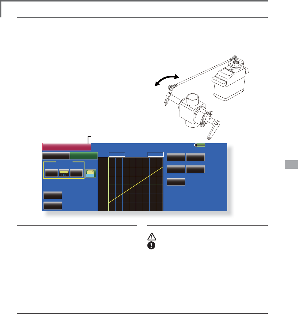
141
<Model Menu (Helicopter Functions)>
85%
POS -100.0%
Linear Separate
+100.0% +100.0%
Model 1 Normal
Gr.
+125
+100
+75
+50
+25
-
25
+0
RATE
Rate A
Single
Tri m
Display
+0.0%
2íVHW
Rate B
+0.0%
IN
ThrottlePitch
0 0
THR Curve
Speed
OUT
THR Curve/Throttle Hover trim
THR
C
urve
T
hi
s funct
i
on a
dj
usts t
h
e t
h
rott
l
e operat
i
on curve
for each condition for optimum the en
g
ine speed to
th
r
o
tt
le
s
t
ick
m
ove
m
e
nt
.
A throttle curve from linear o
p
eration curve to
smoot
h
curve can
b
e set. A
dj
ustment to t
h
e curve
y
ou want to use
i
s poss
ibl
e
by
us
i
n
g
t
h
e 18MZ's
p
owerful Curve Edit Function. U
p
to 17 curve
po
i
nts can
b
e set,
h
owever, w
h
en t
h
e 5 po
i
nts an
d
o
t
h
er po
i
nt
d
ata
i
s use
d
, a smoot
h
curve can
b
e
eas
ily
create
d
by
re
d
uc
i
n
g
t
h
e num
b
er of
i
npu
t
S
RLQWVRIWKHFXUYHWRDQGHQWHULQ
J
WKHVSHFL¿H
G
va
l
ue at t
h
e correspon
di
ng po
i
nts.
ŏ
5HWXUQWR0R
G
H
O
0HQX
ŏ7RXFKWKH>7+5&XUYH@EXWWRQ
L
QWKH0RGHO
0HQXWRFD
OO
W
K
HVHWXSVFUHHQV
K
RZQ
E
H
O
RZ
Normal curve ad
j
ustment
ŏ
1
R
UP
D
O
FX
UY
H
F
U
HD
W
HV
D
EDVLF
FX
UY
H
FH
QW
H
U
HG
D
URXQGKRYHULQJ8VHLWDORQJZLWKWKHQRUPDO
S
LWFKFXUYHDQGDGMXVWVRWKDWXSGRZQFRQWURODW
D
FRQVWDQWHQ
J
LQHVSHHGLVHDVLHVW
I
dle up curve ad
j
ustment
ŏ
6HWDQRUPDOXSFXUYHWKDWPD
L
QWD
L
QVDFRQVWDQW
VS
HHGDWDOOW
L
PHVHYHQZKHQR
S
HUDW
L
RQZK
L
FK
U
HGXFHVWKHS
L
WFKZDVSHU
I
RUPHG
L
Q
ÁL
JKW&UHDWH
D
FXUYHPDWF
K
H
G
WR
O
RR
S
UR
OO
'RURW
K
H
U
S
XUSRVHVDQGWKHLGOHXSFXUYHDFFRUGLQJWRWKH
S
HUIRUPDQFH
O
perat
i
on precaut
i
ons
W
AR
N
I
NG
:
KHQDFWXDOO\VWDUW
L
QJWKHHQJ
L
QHDQG
I
O\
L
QJDOZD\VVHWWKH
L
GOHXSFRQG
L
W
L
RQ
V
Z
L
WFKWR>2))@DQGVWDUWWKHHQJ
L
QH
L
QWKH
L
GO
L
QJPRGH
Setting method
ŏ
*URXSEXWWRQ:KHQ\RXZDQWWRV
L
PXOWDQHRXVO\
H
QWHUWKHVDPHVHWW
L
QJVWRRWKHU
I
XQFW
L
RQVPDNH
W
KHVHWW
L
QJV
L
QWKHJURXSPRGH
,Q
L
W
L
DOVHWW
L
QJ
,Q
W
KLVFDVHWKHVDPHVHWWLQJFRQWHQWVDUHHQWHUHG
W
RWKHRWKHUFRQGLWLRQVLQWKHJURXSPRGH:KHQ
\
RXZDQWWRVHWHDFKFRQGLWLRQLQGH
S
HQGHQWO
\
P
DNHWKHVHWWLQ
J
VDIWHUVHOHFWLQ
J
WKHVLQ
J
OHPRGH
ŏ
7KHFXUYH
J
UDSKG
L
VSOD\PRGHFDQEHVHOHFWHG
7
K
L
V
L
VFRQYHQ
L
HQWZKHQFKHFN
L
Q
J
FXUYHVRWKHU
W
KDQWKHRQHEH
L
Q
J
VHW
>
6QJO@'
L
VSOD\VRQO\WKHFXUYHEH
L
QJVHW
>
)
L
QH7XQ
L
QJ@:KHQ7KURWWOH+RYHUWU
L
P
L
VXVHG
D
FXUYHZLWKWULPDGMXVWPHQWDGGHGLVDOVR
G
L
VSOD\HG
>
$OO&RQG
@
'
L
V
S
OD
\
VWKHWKURWWOHFXUYHR
I
DOOWKH
F
RQG
L
W
L
RQV7KHFXUYHR
I
WKHFRQG
L
W
L
RQFXUUHQWO
\
L
Q
X
VHLVLQGLFDWHGE
\
DEROGOLQH
>
3,77+5
@
7KH
S
LWFKFXUYHRIWKHFRQGLWLRQ
F
XUUHQWO
\
LQXVHLVDOVRGLV
S
OD
\
HG
ŏ
7KHSLWFKFXUYHVHWXSVFUHHQFDQEHFDOOHGZLWK
R
QHWRXFK7K
L
V
L
VFRQYHQ
L
HQWZKHQDOWHUQDWHO\
DG
M
XVW
L
Q
J
WKHVHFXUYHVZ
L
WKWKHS
L
WFKFXUYH
ŏ
7KHVHUYRVSHHGFDQEHVHW$G
M
XVWWKHWKURWWOH
V
S
HHGZKHQWKHWKURWWOH
L
VWRRVHQV
L
W
L
YH
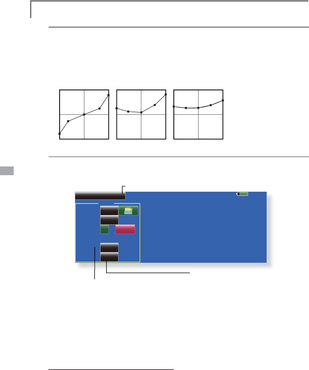
142 <Model Menu (Helicopter Functions)>
Normal Curve Idle-up 1 Curve Idle-up 2 Curve
Ɣ7KURWWOH&XUYH([DPSOH
85%
Model 1
Hover
Throttle Hover
INH
ACT/INH
Mode
Rate
Range
Control
( +0%)
Normal
Gr.
- 30%
100%
NULL
CTRM
Th
e curves s
h
own
b
e
l
ow were create
d
b
y us
i
ng
the Line mode and inputtin
g
the data of the 5 points
0%
(
low side
)
, 25%, 50%
(
center
)
, 75%, 100%
(hi
g
h)
s
id
e at eac
h
con
di
t
i
on. T
h
ey were create
d
b
y
reducin
g
the number points of the line to 5. When
actua
lly
creat
i
n
g
a curve, enter t
h
e
d
ata spec
i
f
i
e
d
per the fusela
g
e (or the reference value).
*For a descri
p
tion of the curve creation method, see the
descri
p
tion at the back of this manual.
Curve settin
g
examples
ŏ5
H
W
X
UQW
R
0
RGH
O0
H
Q
X
Throttle Hover trim
T
he Throttle Hover trim setu
p
screen can be called from the THR Curve setu
p
screen.
ŏ6HWV7KURWWOH+RYHUWULP
ŏ6HWVWKHG
L
DOXVHG
T
h
e
Thr
o
ttl
e
H
ove
r f
u
n
c
ti
o
n trim
s
th
e
thr
o
ttl
e
n
ear t
h
e
h
over
i
ng po
i
nt. Norma
ll
y, use
i
t w
i
t
h
hoverin
g
conditions. Chan
g
es in rotor speed
accompanying changes in the temperature,
h
um
idi
ty, an
d
ot
h
er f
li
g
h
t con
di
t
i
ons can
b
e
trimmed. Ad
j
ust the throttle so that rotor rotation is
most stable. More delicate trimming is also possible
b
y us
i
ng t
hi
s funct
i
on a
l
ong w
i
t
h
t
h
e Hover P
i
tc
h
function.
Setting method
ŏ:KHQXVLQ
J
WKHKRYHULQ
J
QRUPDO
FRQGLWLRQ
RQO\VZLWFKWKH>*U@
J
URXSEXWWRQ
PRGHWRWKH
>6Q
J
O@
V
L
Q
J
OH
PRGHDQGPDNHWKHVHWW
L
Q
J
V
ŏ6HWWKH
I
XQFW
L
RQWR$&7
>21@
ŏ6HOHFWWKHDG
M
XVWPHQWNQRE6HOHFW
L
RQH[DPSOH5
'
ŏ7KHWU
L
PRSHUDW
L
RQPRGH
0RGH&7501250
FD
Q
EH
VH
O
HF
W
HG
C
TRM mode: 0D[
L
PXPUDWHR
I
FKDQJHQHDU
FHQWHUE
\
FHQWHUWU
L
PR
S
HUDW
L
R
Q
N
O
RM mo
d
e:
1
RUPDOWULPKRUL]RQWDOPRYHPHQW
W
ULPRSHUDWLRQ7KHDGYDQWDJHRIXVLQJWKLVPRGH
L
VWKDWKRYHULQJWKURWWOHFDQEHDGMXVWHGZLWKRXW
FKDQ
J
LQ
J
WKHFXUYH
ŏ7ULPDG
M
XVWPHQWUDQ
J
H
5DQ
J
H
VHWWLQ
J
:KHQWKHYDOXH
L
VPDGHVPDOOWU
L
PDFWVRQO\QHDU
W
K
H
FH
QW
H
U
ŏ7KHWU
L
PUDWHFDQEHDG
M
XVWHGDQGWKHRSHUDW
L
RQ
GL
U
HF
W
LR
Q
FD
Q
EH
VH
W
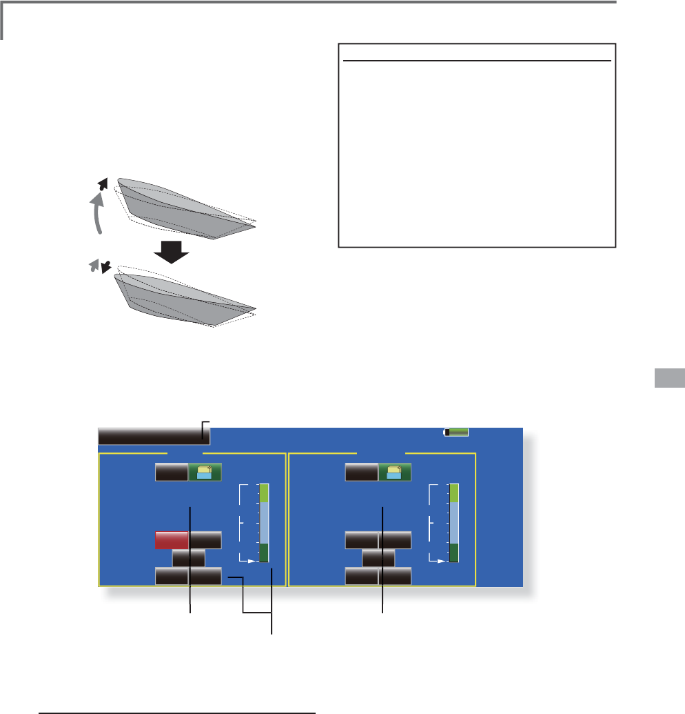
143
<Model Menu (Helicopter Functions)>
85%
Model 1
Pitch
H
100%
0%
L
Acceleration
INH
ACT/INH Gr.
25%
0%
0% 0%
75%
Active POS
Dumping
Rate
Low High
Throttle
H
100%
0%
L
INH
ACT/INH Gr.
25%
0%
0% 0%
75%
Active POS
Dumping
Rate
Close Open
Acceleration Mixing
This function is used to ad
j
ust the pitch an
d
the
t
h
r
o
tt
le
r
ise
ch
ara
c
t
e
r
is
t
ic
at a
ccele
rat
io
n
/
d
ece
l
erat
i
on operat
i
on. An acce
l
erat
i
on funct
i
on
which temporaril
y
increases the pitch and throttle
o
perat
i
ons at t
h
rott
l
e st
i
c
k
acce
l
erat
i
on
/d
ece
l
erat
i
on
o
perat
i
on can
b
e set.
Example o
f
accelerat
i
on
f
unct
i
on use
ŏ
:KHQXVHGDWSLWFKWKH$FFHOHUDWLRQ
I
XQFW
L
RQ
L
VH
II
HFW
L
YHZKHQ\RXZDQWWR
T
XLFNHQWKHUHVSRQVHRIWKHIXVHODJHDW'
Á
LJKWÁLSHWF
:
KHQXVHGKLJKSLWFKWHPSRUDULO\H[FHHGV
P
D[
L
PXPS
L
WFKEXW
L
PPHG
L
DWHO\UHWXUQVWR
P
D[LPXPSLWFK
8V
L
Q
J
$FFHOHUDW
L
RQZ
L
WK3
L
WFK
L
VH
II
HFW
L
YHZKHQ
\
RXZDQWWRPD[
L
P
L
]HVSHHG
I
RU'DHUREDW
L
FV
DQGRWKHUD
L
UFUD
I
WUHVSRQVHV$VDQH[DPSOH´+
L
JK
SL
WFKµWHP
S
RUDU
L
O
\
RYHUU
L
GHV´PD[
L
PXP
SL
WFKµDQG
LPPHGLDWHO
\
UHWXUQVWRWKHPD[LPXP
S
LWFK
S
RVLWLRQ
ŏ
5
H
W
X
UQW
R
0
RGH
O0
H
Q
X
ŏ
7RXFKWKH>$FFHOHUDW
L
RQ@EXWWRQ
L
QWKH0RGHO
0
HQXWRFD
OO
W
K
HVHWXSVFUHHQV
K
RZQ
E
H
O
RZ
ŏ
3
L
WFKVHWW
L
QJ
ŏ
2SHUDW
L
RQSR
L
QWVHWW
L
QJ
ŏ
7KURWWOHVHWW
L
QJ
Setting method
ŏ
$FFHOHUDWLRQFDQEHVHWDWERWKVHWWLQ
J
DW
D
FFHOHUDW
L
RQ
K
LJ
K
DQGVHWW
L
Q
J
DWGHFHOHUDW
L
RQ
ORZ
7KHRSHUDW
L
RQSR
L
QW
L
VG
L
VSOD\HGRQDJUDSK
ŏ
$FFHOHUDW
L
RQUDWHVHWW
L
QJ
5DWH
ŏ
7KHUHWXUQWLPHDIWHURSHUDWLRQ'XPSLQJFDQEH
VHW
ŏ
7KHR
S
HUDWLRQ
S
RLQWDWDFFHOHUDWLRQDQG
G
HFHOHUDWLRQFDQEHVHW:KHQDQRSHUDWLRQSRLQW
L
VH[FHHGHGDFFHOHUDWLRQLVSHUIRUPHG
Note: When usin
g
the Acceleration funtion, since the pitch
stroke
i
s lar
g
e, make
y
our sett
i
n
g
s so there
i
s no b
i
nd
i
n
g
of
y
our l
i
nka
g
e.
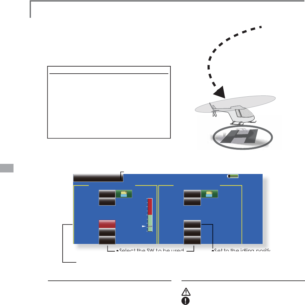
144 <Model Menu (Helicopter Functions)>
85%
Model 1 Normal
Throttle Hold (Cut)
100%
0%
Throttle Hold
INHACT/INH
ManualMode
Gr.
ON
0
17%
Switch
Speed
Hold Pos.
Auto Pos.
Throttle Hold (Idle)
INHACT/INH
ManualMode
Gr.
ON
0
+0%
Switch
Speed
,GOH2íVHW
Auto Pos.
Throttle Hold
T
his function sets the throttle cut
p
osition at
auto rotat
i
on
di
ve. T
h
e t
h
rott
l
e pos
i
t
i
on can a
l
so
b
e
s
et to an
idli
n
g
pos
i
t
i
on separate from t
h
e t
h
rott
l
e
cut position. Settin
g
of these 2 positions can be
s
e
l
ecte
d
b
y sw
i
tc
h
. T
hi
s a
ll
ows use for sw
i
tc
hi
ng
d
ur
i
n
g
tra
i
n
i
n
g
.
E
xample o
f
use
ŏ
6LQFH7KURWWOH+ROGKDVPRGHV&XWDQG
,GOH
XV
L
QJ
L
W
L
QWKH,GO
L
QJPRGHGXU
L
QJ
W
UDLQLQJDQGLQWKH&XWPRGHZKHQ
V
WRSS
L
QJWKHHQJ
L
QHDWPHHWVHWF
L
V
F
RQYHQLHQW
1RWH:KHQWKURWWOHKROGLVVHWWR
2
1LQWKHQRUPDO
FRQG
L
W
L
RQWKURWWOHKROGDFWVDQGWKHWKURWWOHVHUYR
L
VGHDFW
L
YDWHG$OZD\VVHWWKURWWOHKROGWR21
L
QWKH
K
R
O
G
FR
Q
GL
W
LR
Q
ŏ5HWXUQWR0R
G
H
O
0HQ
X
ŏ7RXFKWKH
>
7KURWWOH+ROG
@
EXWWRQLQWKH0RGHO
0HQXWRFDOOWKHVHWX
S
VFUHHQVKRZQEHORZ
ŏ6HWWRWKHHQJLQHVWRSSRVLWLRQ
ŏ6HOHFW
WKH
6:
WR
EH
XVHG
ŏ6HWWRWKHLGOLQJSRVLWLRQ
S
ett
i
n
g
method
ŏ2
S
HUDWLRQPRGHVHOHFWLR
Q
Ma
n
ual
m
ode:
7K
H
WKU
R
WWO
H
K
R
O
G
I
X
Q
F
WL
R
QL
V
R
S
HUDWHGE
\
VZLWFKR
S
HUDWLRQRQO
\
Auto mo
d
e:7KHWKURWWOHKROGIXQFWLRQRSHUDWLRQLV
OL
QNHGWRWKHWKURWWOHVW
L
FNSRV
L
W
L
RQ
Auto pos
i
t
i
on sett
i
n
g
::KHQWKH$XWRPRGHZDV
V
HOHFWHGWKHWKURWWOHSRV
L
W
L
RQ
DXWRSRV
L
W
L
RQ
FDQ
E
HVHOHFWHG0RYHWKHWKURWWOHVW
L
FNWRWKHSRV
L
W
L
RQ
\
RXZDQWWRVHWDQGWRXFKWKH
DXWRSRV
L
W
L
RQ
EX
WW
R
Q
ŏ+ROGSRVLWLRQDGMXVWPHQW
T
hrottle Hold (Cut) VHWVWKHWKURWWOHFXW
S
RVLWLRQ
$G
M
XVWLWVRWKDWWKHFDUEXUHWRULVIXOORSHQ
T
hrottle Hold
(
Idle
)
:0DNHWK
L
VDG
M
XVWPHQWWR
PD
L
QWD
L
Q
L
GO
L
Q
J
I
RUWUD
L
Q
L
Q
J
$G
M
XVWPHQWVFDQEH
PDGHEDVHGRQWKHWKURWWOHFXUYH
L
GOHSRV
L
W
L
RQ
ŏ7KHWKURWWOHVHUYRRSHUDW
L
QJVSHHGFDQEH
DG
M
XVWHG
6SHHG
ŏ7KURWWOHFXWRUWUDLQLQJIXQFWLRQFDQEHVZLWFKHG
E\
KROGIXQFWLRQVHOHFWRUVZLWFK
O
p
erat
i
on
p
recaut
i
ons
W
AR
N
I
NG
:KHQVWDUW
L
QJWKHHQJ
L
QHFRQ
IL
UPWKDW
WKH
L
GOHXSFRQG
L
W
L
RQDQGWKURWWOHKROG
FRQG
L
W
L
RQDUH>2))@
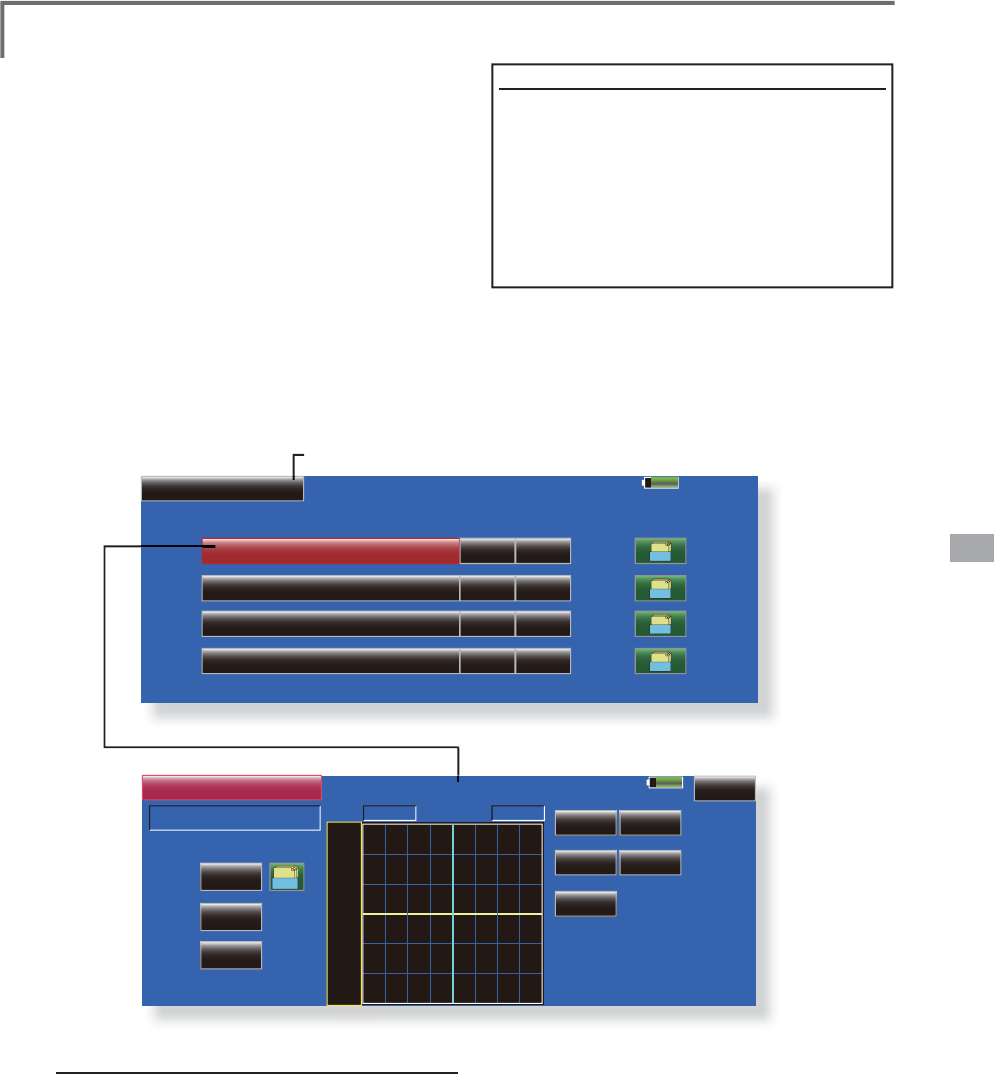
145
<Model Menu (Helicopter Functions)>
85%
Model 1 Normal
Mixing ACT Switch Group
Swash Mix
AIL to ELE INH Gr.
ON
ELE to AIL INH Gr.
ON
PIT to AIL INH Gr.
ON
PIT to ELE INH Gr.
ON
100%
POS +0.0%
Linear
Return
Separate
+100.0% +100.0%
Model 1 Normal
Gr.
+150
+100
+50
+0
-50
-150
-100
RATE
Rate A
INH
ACT
ON
Switch
OFF
Tri m
+0.0%
2íVHW
Rate B
+0.0%
6ZDVK0L[
AIL to ELE
Swash Mixing
The swash mix function is used to correct the
swas
h
p
l
ate
i
n t
h
e a
il
eron
(
ro
ll)
di
rect
i
on an
d
el
evator
(
c
y
c
li
c p
i
tc
h)
correspon
di
n
g
to eac
h
op
eration of each condition.
Adj
ustment
by
i
n
d
epen
d
ent curve for a
il
eron,
e
levator, and
p
itch o
p
erations is
p
ossible. The
o
perat
i
on can
b
e smoot
hl
y a
dj
uste
d
b
y ca
lli
ng up
th
e “Curve setup” screen
by
touc
hi
n
g
t
h
e
b
utton
t
hat corresponds to the mixing and direction which
n
eeds
co
rr
ec
t
io
n
.
E
xam
p
le of use
ŏ
$VDQH[DPSOHXVHVZDVKP
L
[
L
QJWRFRUUHFW
X
QGHV
L
UDEOHWHQGHQF
L
HV
L
QWKHUROOG
L
UHFW
L
R
Q
ŏ
)RUDFRQG
L
W
L
RQZK
L
FKXVHV$,/WR(/(VHWWK
L
V
I
XQFW
L
RQWR21:KHQUD
L
V
L
QJWKHQRVHDWD
UL
JKWUROOZKHQWKH5DWH%V
L
GH
L
V
L
QSXWDQG
W
KHU
L
JKWD
L
OHURQ
L
VRSHUDWHGWKHHOHYDWRU
P
RYHVWRWKHGRZQV
L
GH7XQHE\DG
M
XVW
L
QJ
W
KH5DWH)RUU
L
JKWUROODG
M
XVWWRWKH5DWH$
VL
GH
ŏ
5HWXUQWR0RGHO0HQX
ŏ
7RXFKWKH
>
6ZDVK0L[
@
EXWWRQLQWKH0RGHO
0
HQXWRFDOOWKHVHWX
S
VFUHHQVKRZQEHORZ
S
ett
i
ng method
ŏ
:KHQXV
L
Q
J
WK
L
V
I
XQFW
L
RQWRXFKWKH>,1+@EXWWRQ
D
QGG
L
VSOD\>21@RU>2))@
ŏ
:KHQ
\
RXZDQWWRVHWWKHVDPHFRQWHQWVDWRWKHU
F
RQGLWLRQVVHOHFWWKHJURXSPRGH*U:KHQ
\
RXZDQWWRVHWWKHVHOHFWHGFRQGLWLRQRQO
\
VHOHFW
W
KHVLQJOHPRGH6QJO
ŏ
7KHFRUUHFWLRQUDWHFDQEHVHWE\FXUYH
ŏ
$VZLWFKFDQEHVHW
:KHQ>18//@
L
VVHWWKHVZDVKP
L
[
L
Q
J
I
XQFW
L
RQ
L
V
R
SHUDWHGE\PHUHO\VHOHFW
L
Q
J
WKHFRQG
L
W
L
RQ
:KHQVHWWLQJDQ>21@>2))@VZLWFKWRXFKWKH
>18//@EXWWRQDQGVHWWKHVZLWFKDQGLWV21
S
RVLWLRQDWWKH6ZLWFK!VFUHHQ
ŏ
7U
L
PRQR
II
VHWW
L
Q
J
<
RXFDQVHOHFWP
L
[
L
Q
J
FKDUDFWHU
L
VW
L
FVH
L
WKHUZ
L
WK
W
U
L
P
R
UZ
L
WK
RX
WWU
L
P
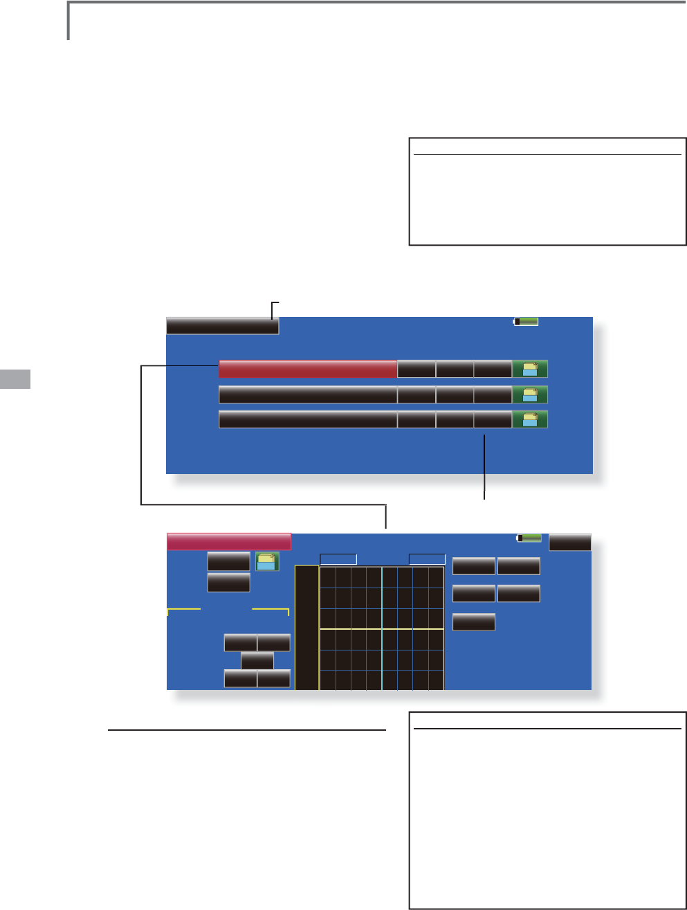
146 <Model Menu (Helicopter Functions)>
85%
Model 1 Normal
Mixing ACT Switch Group
Throttle Mix
AIL to THR INH Gr.
ON
ELE to THR INH Gr.
ON
RUD to THR INH Gr.
ON
Mode
CTRM
CTRM
CTRM
85%
POS +0.0%
Linear
Return
Separate
+100.0% +100.0%
Model 1 Normal
Gr. +150
+100
+50
+0
-50
-
150
-100
RATE
Rate A
INH
ACT
ON
Switch
+0.0%
2íVHW
Rate B
+0.0%
AIL to THR
-50%
0%
0% 0%
+50%
Act.POS.
Dump.
Rate
Acceleration
Left Right
Throttle Mixing
T
his function corrects slowin
g
of en
g
ine
s
pee
d
cause
d
b
y swas
h
p
l
ate operat
i
on at a
il
eron
or e
l
evator operat
i
on. T
h
e met
h
o
d
of app
lyi
n
g
clockwise or counterclockwise tor
q
ue when
pi
rouett
i
ng can a
l
so
b
e correcte
d
.
An acceleration function which temporaril
y
i
n
c
r
e
a
ses
t
he
t
h
r
o
tt
le
side
co
rr
ec
t
io
n rat
e
r
el
at
ive
t
o
rap
id
st
i
c
k
operat
i
on can a
l
so
b
e set.
W
h
en correct
i
on
i
s necessary, touc
h
t
h
e m
i
x
i
ng
correspondin
g
to the mixin
g
that needs correction
to call the curve setu
p
screen, and then correct the
sl
ow
i
ng.
S
ett
i
ng example
ŏ
$,/WR7+5DSSOLHVDORDGWRWKHHQ
J
LQHDQG
F
RUUHFWVVLQNLQ
J
RIWKHHQ
J
LQHVSHHGZKHQ
W
KHWKURWWOHVWLFNZDVRSHUDWHG(Q
J
LQH
U
DFLQ
J
FDQEHDG
M
XVWHGLQGHSHQGHQWO\DW
W
KHUL
J
KWDLOHURQDQGOHIWDLOHURQE\5DWHV$
D
Q
G
%
ŏ5HWXUQWR0R
G
H
O
0HQ
X
ŏ7RXFKWKH
>
7KURWWOH0L[
@
EXWWRQLQWKH0RGHO
0HQXWRFDOOWKHVHWX
S
VFUHHQVKRZQEHORZ
S
etting method
ŏ:KHQXV
L
Q
J
WK
L
V
I
XQFW
L
RQWRXFKWKH>,1+@EXWWRQ
DQGG
L
VSOD\>21@RU>2))@
ŏ:KHQ\RXZDQWWRVHWWKHVDPHFRQWHQWVDWRWKH
U
FRQG
L
W
L
RQVVHOHFWWKHJURXSPRGHO
*U
:KHQ
\
RXZDQWWRVHWWKHVHOHFWHGFRQGLWLRQRQO
\
VHOHFW
WKHVLQJOHPRGH6QJO
ŏ7KHFRUUHFWLRQUDWHFDQEHVHWE
\
FXUYH
ŏ$VZLWFKFDQEHVHW
:
KHQ>18//@LVVHWWKHIXQFWLRQLVRSHUDWHGE\
PHUHO\VHOHFW
L
Q
J
WKHFRQG
L
W
L
RQ
:
KHQVHWW
L
Q
J
DQ>21@>2))@VZ
L
WFKWRXFKWKH
>18//@EXWWRQDQGWKHQVHWWKHVZ
L
WFKDQG
L
WV21
GL
UHFW
L
RQDWWKH6Z
L
WFK!VFUHHQ
ŏ&750PRGH7KHPL[LQ
J
UDWHLVUHGXFHGE\
WKHWKURWWOHVWLFNKLJKDQGORZSRVLWLRQ
ŏ/,1($5PRGH&RQVWDQWPL[LQJUDWHWRDOOWKH
WKURWWOHVWLFNUDQ
J
HV
<Accelerat
i
on
f
unct
i
on sett
i
n
g
>
ŏ
$FFHOHUDWLRQFDQEHVHWIRUERWKVHWWLQ
J
V
+L
J
K
DQG
/RZ
DWPD[LPXPFRUUHFWLRQ
UD
W
H
ŏ
$FFHOHUDWLRQUDWHVHWWLQ
J
5DWH
ŏ
7KHUHWXUQWLPH
'XPS
DIWHURSHUDWLRQFDQ
EH
VH
W
ŏ
7KHR
S
HUDWLRQ
S
RLQWZKHQWKHFRUUHFWLRQ
UD
W
H
L
V
LQ
F
U
HDVHG
D
Q
G
GHF
U
HDVHG
FD
Q
EH
V
HWLQGH
S
HQGHQWO
\
:KHQDQR
S
HUDWLRQ
S
RLQWLVH[FHHGHGDFFHOHUDWLRQR
S
HUDWLRQ
LV
S
HUIRUPHG
ŏ0RGHVHOHFW
L
R
Q
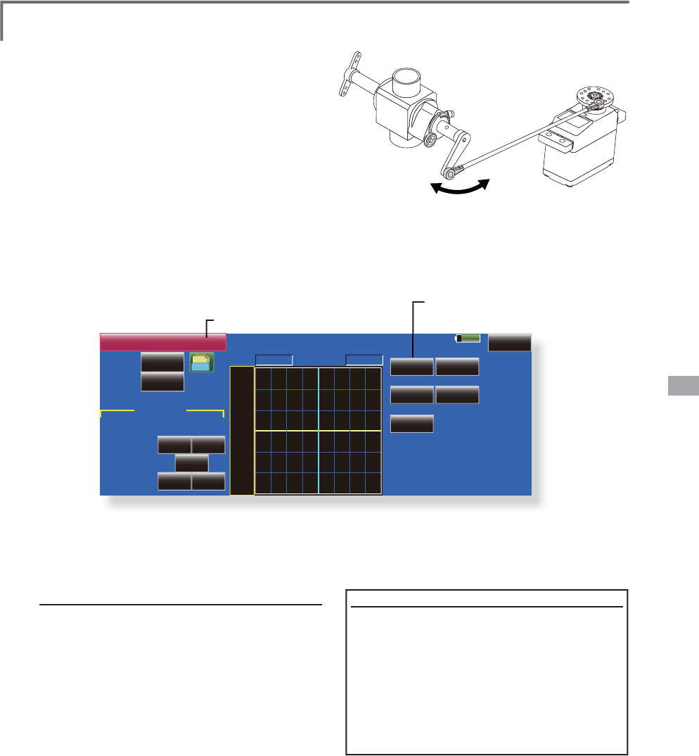
147
<Model Menu (Helicopter Functions)>
100%
POS +0.0%
Linear
Return
Separate
+100.0% +100.0%
Model 1 Normal
Gr. +150
+100
+50
+0
-50
-150
-100
RATE
Rate A
INH
ACT
ON
Switch
+0.0%
2íVHW
Rate B
+0.0%
PIT to Needle
25%
0%
0% 0%
75%
Act.POS.
Dump.
Rate
Acceleration
Low High
PIT to Needle Mixing
This mixin
g
is used when the en
g
ine is equipped
wi
t
h
n
eedle
co
ntr
ol
o
r
o
t
he
r f
uel
-a
i
r m
i
xt
u
r
e
adj
ustment. A nee
dl
e curve can
b
e set.
A
n acce
l
erat
i
on funct
i
on w
hi
c
h
temporar
il
y
i
ncreases nee
dl
e operat
i
on at t
h
rott
l
e st
i
c
k
a
cceleration/deceleration o
p
eration can be set.
T
he
r
ise
ch
ara
c
t
e
r
is
t
ic
o
f t
he
n
eedle
se
r
vo
at
a
cce
l
erat
i
on an
d
d
ece
l
erat
i
on operat
i
on can
b
e
a
d
j
usted.
ŏ
5HWXUQWR0RGHO0HQX
ŏ
7RXFKWKH
>
3,7WR1HHGOH
@
EXWWRQLQWKH0RGHO
0
HQXWRFDOOWKHVHWX
S
VFUHHQVKRZQEHORZ
S
ett
i
n
g
method
ŏ
:KHQXVLQJWKLVIXQFWLRQWRXFKWKH>,1+@EXWWRQ
D
QGGLV
S
OD
\
>
21
@
RU
>
2))
@
ŏ
:
K
HQ
\
RXZDQWWRVHWW
K
HVDPHFRQWHQWVDWRW
K
H
U
F
RQGLWLRQVVHOHFWWKH
J
URXSPRGH
*U
:KHQ
\RXZDQWWRVHWWKHVHOHFWHGFRQGLWLRQRQO\VHOHFW
W
KHV
L
Q
J
OHPRGH
6Q
J
O
ŏ
$QHHGOHFXUYHFDQEHVHW
ŏ
$
V
Z
L
W
F
K
FD
Q
EH
VH
W
:KHQ
>
18//
@
L
VVHWWKH
I
XQFW
L
RQ
L
VR
S
HUDWHGE
\
P
HUHO\VHOHFW
L
QJWKHFRQG
L
W
L
RQ
:KHQVHWWLQJDQG>21@>2))@VZLWFKWRXFKWKH
>
18//
@
EXWWRQDQGVHWWKHVZLWFKDQGLWV21
G
LUHFWLRQDWWKH
6
ZLWFK!VFUHHQ
<
Acceleration function settin
g
>
ŏ
$FFHOHUDWLRQFDQEHVHWDWERWKVHWWLQ
J
D
WDFFHOHUDWLRQ
+L
J
K
DQGVHWWLQ
J
DW
G
HFHOHUDWLRQ
/RZ
ŏ
7KHDFFHOHUDWLRQUDWH
5DWH
DQGWKHUHWXUQ
W
LPHDIWHURSHUDWLRQ
'XPS
FDQEHVHW
ŏ
$QRSHUDWLRQSRLQW
2SHUDWLRQ3RLQW
DW
DFFH
O
H
U
D
WL
R
Q
D
Q
G
GHFH
O
H
U
D
WL
R
Q
FD
Q
EH
VH
W
:
KHQDQR
S
HUDWLRQ
S
RLQWZDVH[FHHGHG
D
FFHOHUDWLRQR
S
HUDWLRQLV
S
HUIRUPHG
ŏ1RUPDOO\XVH>/LQH@W\SH
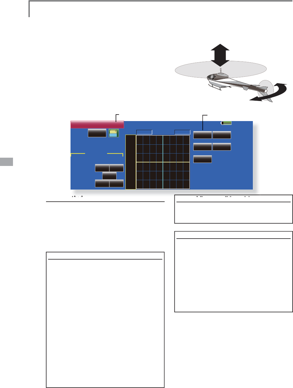
148 <Model Menu (Helicopter Functions)>
100%
POS +0.0%
Linear Separate
Model 1 Normal
Gr. +150
+100
+50
+0
-50
-150
-100
RATE
Rate A
INH
ACT
+0.0%
+0.0% +0.0%
2íVHW
Rate B
+0.0%
PIT to RUD
25%
0%
0% 0%
75%
Act.POS.
Dump.
Rate
Acceleration
Low High
PIT to RUD Mixing (Revolution Mixing)
Use this mixin
g
when
y
ou want to suppress the
react
i
on torque generate
d
b
y ma
i
n rotor p
i
tc
h
an
d
s
pee
d
c
h
an
g
es at p
i
tc
h
operat
i
on. A
dj
ust so t
h
at t
h
e
n
ose does not move in the rudder direction.
An acce
l
erat
i
on funct
i
on w
hi
c
h
temporar
ily
increases the correction rate at throttle stic
k
acce
l
erat
i
on
/d
ece
l
erat
i
on operat
i
on can
b
e set. T
h
e
m
i
x
i
n
g
rate at acce
l
erat
i
on
/d
ece
l
erat
i
on can
b
e set.
However, w
h
en a GY Ser
i
es or ot
h
er
h
ea
di
ng
hold
gy
ro is used, since correction is performed b
y
ŏ5HWXUQWR0R
G
H
O
0HQ
X
ŏ7RXFKWKH>3,7WR58'@EXWWRQ
L
QWKH0RGHO
0HQXWRFDOOWKHVHWXSVFUHHQVKRZQEHORZ
Setting method
ŏ:KHQXV
L
QJWK
L
V
I
XQFW
L
RQWRXFKWKH>,1+@EXWWRQ
DQGGLV
S
OD
\
>
21
@
RU
>
2))
@
ŏ:
K
HQ
\
RXZDQWWRVHWW
K
HVDPHFRQWHQWVDWRW
K
H
U
FRQGLWLRQVVHOHFWWKHJURXSPRGH*U:KHQ
\
RXZDQWWRVHWWKHVHOHFWHGFRQGLWLRQRQO\VHOHFW
WKHVLQ
J
OHPRGH
6Q
J
O
ŏ$P
L
[
L
Q
J
FXUYH
L
VVHW
<
Normal condition mixing curve>
7KHP
L
[
L
QJFXUYHUDWHVWDUWV
I
URPDVPDOO
YD
O
XH
)RUDURWRUZ
L
WKDFORFNZ
L
VHRSHUDW
L
RQ
G
L
UHFW
L
RQ
SRODU
L
W\
ZKHQS
L
WFKZDV
RSHUDWHGDWWKHSOXVV
L
GHVHWVRWKDWP
L
[
L
QJ
L
V
L
QWKHFORFNZ
L
VHG
L
UHFW
L
RQ)
L
UVWWU
L
PDW
KRYHU
L
QJDQGWKHQDG
M
XVWWKHQHXWUDO
SRV
L
W
L
RQ
$G
M
XVWPHQWEHWZHHQVORZDQGKRYHU
L
Q
J
5HSHDWHGO\KRYHU
I
URPWDNHR
II
DQGODQG
I
URPKRYHU
L
QJDWDFRQVWDQWUDWHPDWFKHG
WR\RXURZQUK\WKPDQGDG
M
XVWWKHS
L
WFKVR
WKHQRVHGRHVQRWGH
Á
HFWZKHQWKHWKURWWOH
L
VUD
L
VHGDQGORZHUHG
7KURWWOHK
L
JKV
L
GH
XSWRFO
L
PE
L
QJ
I
URP
KRYHU
L
QJDQGG
L
Y
L
QJKRYHU
L
QJ
*Repeat climbin
g
and divin
g
from hoverin
g
at a constan
t
rate matched to
y
our own rh
y
thm and ad
j
ust the pitch so
th
at t
h
e nose
d
oes not
d
ef
l
ect w
h
en t
h
e t
h
rott
l
e
i
s ra
i
se
d
an
d
l
owere
d
.
ŏ
1RUPDOO
\
XVH
>
/LQH
@
W
\S
H
the
gy
ro, this mixin
g
is not used. If this function is
use
d
w
h
en t
h
e gyro operat
i
on mo
d
e
i
s t
h
e AVCS
mo
d
e, t
h
e neutra
l
pos
i
t
i
on w
ill
c
h
an
g
e.
<Idle up condition mixing curve>
6
HWWKHP
L
[
L
Q
J
UDWHVRWKDWWKHUXGGHUG
L
UHFW
L
RQDW
K
L
J
KVSHHGÁL
J
KWLVVWUDL
J
KWDKHDG$G
M
XVWIRUHDFK
F
RQGLWLRQXVHG
<Accelerat
i
on
f
unct
i
on sett
i
ng>
ŏ
$FFHOHUDW
L
RQRSHUDW
L
RQFDQEHSHU
I
RUPHG
I
RUERWKVHWW
L
QJDWDFFHOHUDW
L
RQ
+
L
JK
DQG
V
HWWLQJDWGHFHOHUDWLRQ/RZ
ŏ
$FFHOHUDW
L
RQUDWHVHWW
L
QJ
5DWH
ŏ
7KHUHWXUQW
L
PHD
I
WHURSHUDW
L
RQ
'XPS
FDQ
E
HVHW
ŏ
$QRSHUDW
L
RQSR
L
QW
2SHUDW
L
RQ3R
L
QW
DW
D
FFHOHUDWLRQDQGGHFHOHUDWLRQFDQEHVHW
LQGHSHQGHQWO\:KHQDQRSHUDWLRQSRLQW
Z
DVH[FHHGHGDFFHOHUDW
L
RQRSHUDW
L
RQ
L
V
S
HU
I
RUPHG
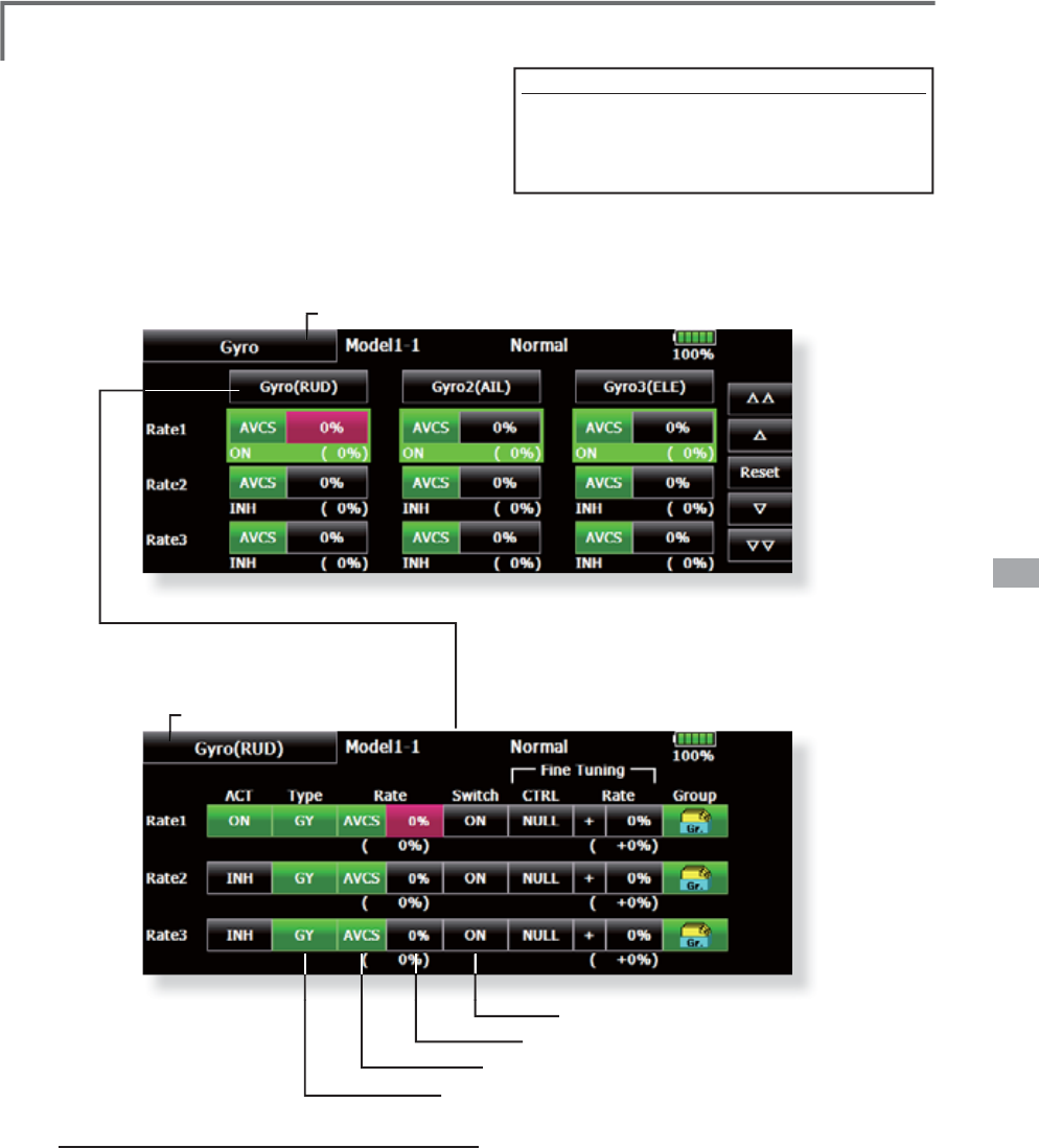
149
<Model Menu (Helicopter Functions)>
Gyro Mixing
I
t is mixin
g
onl
y
for a G
y
ro in the case of usin
g
a
Futa
b
a GY ser
i
es Gyro.
S
ensitivit
y
and operational mode (Normal mode
/
GY mo
d
e
)
can
b
e set up for t
h
ree Gyro for every
c
on
di
t
i
on, respect
i
ve
ly
.
1
RWH$OZD\VVHWERWK
$&7
DQG
7ULP
IRUWKH>*\UR@
I
XQFW
L
RQ
ŏ5HWXUQWR*
\
UR0HQ
X
ŏ5
H
W
X
UQW
R
0
RGH
O0
H
Q
X
ŏ7RXFKWKH>*\UR@EXWWRQLQWKH0RGHO0HQX
WRFDOOWKHVHWX
S
VFUHHQVKRZQEHORZ
ŏ$VHWX
S
RIWKHPRGHRI*
\
URVDQG5HWH
FDQEHSHUIRUPHGRQWKLVVFUHHQ
ŏ$GHWDLOHGVHWX
S
RIHDFK*
\
URFDQEH
SHUIRUPHGRQWKLVVFUHHQ
Setting method
ŏ
7RXFKWKH>,1+@EXWWRQR
I
WKHUDWHWREHXVHGDQG
GL
VSOD\>21@
ŏ
:KHQ\RXZDQWWRVHWWKHVDPHFRQWHQWVDWRWKHU
F
RQG
L
W
L
RQVVHOHFWWKHJURXSPRGH
*U
:KHQ
\
RXZDQWWRVHWWKHVHOHFWHGFRQG
L
W
L
RQRQO
\
VHOHFW
W
KHVLQJOHPRGH6QJO
ŏ
7KU
HH
U
D
W
HV
FD
Q
EH
V
ZLW
F
K
HG
I
R
U
HDF
K
FR
Q
G
LWL
R
Q
5DWH5DWH5DWH
ŏ
$ÀQHWXQLQ
J
95FDQEHVHW
S
ett
i
ng example
ŏ
1
RUPDOO\LWLVFRQYHQLHQWWRSUHVHWKL
J
K
V
HQVLWLYLW\5DWHDQGORZVHQVLWLYLW\5DWH
ZKHQHLWKHUWKH$9&6PRGHRU1RUPDO
PRGH
L
V
XVHG
ŏ6HOHFWVWKHVHOHFWRUVZ
L
WFK
ŏ$G
M
XVWVWKHJ\URVHQV
L
W
L
Y
L
W\E\UDWH
ŏ
6
H
O
HFWV
>
$9
&6@
RU
>
1RU
@
ŏ6HOHFWWKHW\SHR
I
J\URXVHG
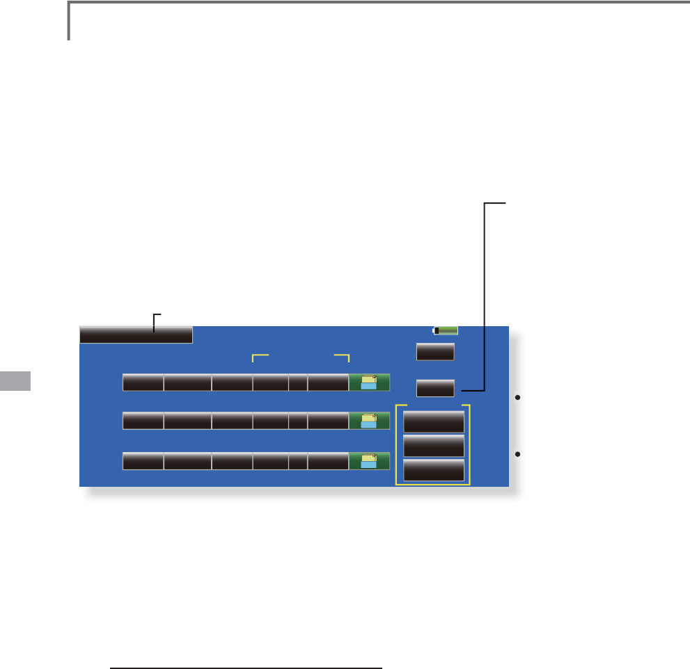
150 <Model Menu (Helicopter Functions)>
85%
NULL
ACT
OFF
Switch
Rate1
Model 1
Governor
50.0%
Rate CTRL Rate Group Mode
+ 0%
%
2000
2000rpm
1500rpm
1000rpm
Normal
( 50.0%) ( + 0.0%)
Rate2
Rate3
Fine Tuning
NULLOFF50.0% + 0%
( 50.0%) ( + 0.0%)
OFF50.0% + 0%
( 50.0%) ( + 0.0%)
INH
INH
INH NULL
Gr.
Gr.
Gr.
Set GOV
Governor Mixing
T
his is used to switch the RPM of the helico
p
ters
h
ea
d
. U
p
to 3 rates can
b
e set for eac
h
con
di
t
i
on.
*
T
h
e
g
overnor
i
s use
d
by
connect
i
n
g
t
h
e
g
overnor spee
d
sett
i
n
g
c
h
anne
l
to CH7
(i
n
i
t
i
a
l
sett
i
n
g)
.
*When usin
g
an independent
g
overnor [ON]/[OFF] switch,
connect t
h
e AUX
(
[ON]
/
[OFF]
)
connector of t
h
e
g
overnor to
C
H8
(i
n
i
t
i
a
l
sett
i
n
g)
an
d
set t
h
e sw
i
tc
h
to Governor2 at t
h
e
Funct
i
on menu of t
h
e L
i
n
k
age Menu.
ŏ
5HWXUQWR0R
G
H
O
0HQ
X
ŏ7RXFKWKH
>
*RYHUQRU
@
EXWWRQRIWKH0RGHO
0HQXWRFDOOWKHVHWX
S
VFUHHQVKRZQEHORZ
ŏ:K
H
QWK
H
´0
RGH
µ
EX
WW
R
Q
R
Q
WKH
*
RYHUQRUVFUHHQLV
S
UHVVHGWKHGLV
S
OD
\
PRGHLV
V
ZLW
F
K
HG
U
S
PPRG
H
U
S
PPRGH
ŏ7KHU
S
PPRGHDQG
U
S
PPRGHDUHGLIIHUHQW
ZKHQWKHUDWHLV
USP
RU
J
UHDWHU$W
UDWHVEHORZWKHU
S
P
GLV
S
OD
\
LVWKHVDPHIRUERWK
P
RGHV
:KHQWKHU
S
PPRGH
LVVHW U
S
P
7K
H
P
D
[LP
X
PY
D
O
XH
L
V
U
S
P
:KHQWKHU
S
PPRGH
LVVHW U
S
P
7K
H
P
D
[LP
X
PY
D
O
XH
LV U
S
P
&RQYHQWLRQDO
VSHFLÀFDWLRQV
ŏ7KHUHLVQRFKDQ
J
HLQWKH
WUDQVPLWWHURXW
S
XWHYHQ
ZKHQWKHU
S
PPRGH
DQGU
S
PPRGHDUH
VZLWFKHG
&
DOLEUDWLRQ
PXVWEH
S
HUIRUPHGDWWKH
J
RYHUQRUVLGH
S
etting method
ŏ
7RXFKWKH>,1+@EXWWRQRIWKHUDWHWREHXVHGDQG
G
L
VSOD\>21@
ŏ
:KHQ\RXZDQWWRVHWWKHVDPHFRQWHQWVDWRWKHU
I
XQFW
L
RQVVHOHFWWKHJURXSPRGH
*U
:KHQ\RX
Z
DQWWRVHWWKHVHOHFWHGFRQG
L
W
L
RQRQO
\
VHOHFWWKH
VLQJOHPRGH6QJO
ŏ
7KUHHVSHHGVUDWHVFDQEHVHWIRUHDFKFRQGLWLRQ
5DWH5DWH5DWH
ŏ
(QGSRLQWLQLWLDOL]DWLR
Q
7KH
J
RYHUQRURXWSXWFKDQQHOHQGSRLQW
$79
´WUDYHOµDQG´O
L
P
L
WµDUHQRZ
L
Q
L
W
L
DO
L
]HGZKHQWKH
J
RYHUQRUVHWW
L
Q
J
´2SHUDWHµEXWWRQZDVSUHVVHG
ŏ:KHQVZ
L
WFKHG
I
URP,1+WR21RU2))
´WUDYHOµ
L
V
L
Q
L
W
L
DO
L
]HGWRDQG´O
L
P
L
Wµ
L
V
L
Q
L
W
L
DO
L
]HGWR
ŏ:KHQ´2
S
HUDWHµRIUDWHVDQGLVVZLWFKHG
WR,1+XQGHUDOOFRQGLWLRQV´WUDYHOµLVLQLWLDOL]HGWR
DQG´OLPLWµLVLQLWLDOL]HGWR
*When usin
g
the Fuel Mixture function, the mixture servo is
contro
ll
e
d
from t
h
e
g
overnor. W
h
en transm
i
tt
i
n
g
t
h
e m
i
xture
curve
d
ata from t
h
e transm
i
tter to t
h
e
g
overnor, t
h
e
g
overnor
A
UX
(
m.trm
)
connector must
b
e connecte
d
to Governor2
f
unct
i
on an
d
governor s
id
e sett
i
ng performe
d
. See t
h
e
governor instruction manual.
1RWH$OZD\VVHW$FWDQG7ULPWR>18//@IR
U
>
*RYHUQRU
@
DQG
>
*RYHUQRU
@
RIWKH)XQFWLRQPHQX
7KHVXEWULPRI>*RYHUQRU@LVPDGH
0DNHWKHUHYHUVHGLUHFWLRQQRUPDO
$OVRWK
L
VP
L
[
L
QJDQGWKHJRYHUQRUV
L
GHVSHHG
VHWW
L
QJPXVWEHPDWFKHGEH
I
RUHKDQGE\WKH
I
ROORZLQJPHWKRG
ŏ
6HWVRWKDWZKHQWKHJRYHUQRUVLGHLVSODFHGLQ
WKHVSHHGVHWWLQJLWHPVWDWHDQG>USP@RI
6
HW*29RIWKHVFUHHQDERYHLVWRXFKHGWKH
J
RYHUQRUVSHHGLVVHWWRZKHQWKH>USP@
EXWWRQ
L
VWRXFKHGWKH
J
RYHUQRUVSHHG
L
VVHWWR
DQGZKHQWKH>USP@EXWWRQ
L
VWRXFKHG
WKHJRYHUQRUVSHHG
L
VVHWWR
ŏ
:KHQ
\
RXZDQWWRUHDGWKHV
S
HHGG
L
UHFWO
\
S
UHVV
WKH
>
@
EXWWRQDQGGLV
S
OD
\
>
U
S
P
@
ŏ
7KHVSHHGFDQEHZLWFKHGE\VHWWLQJDVZLWFK
$OVRZKHQ>2))@LVVHWLQVWHDGRIVSHHGVHWWLQJ
WKH
J
RYHUQRUFDQEHWXUQHG>21@>2))@ZLWKRXW
VHWWLQ
J
DVHSDUDWH>21@>2))@VZLWFK
ŏ
$VSHHG
À
QHWXQ
L
Q
J
95FDQEHVHW
*
VR selection, ad
j
ustment width, and ad
j
ustment direction
c
an
b
e set.
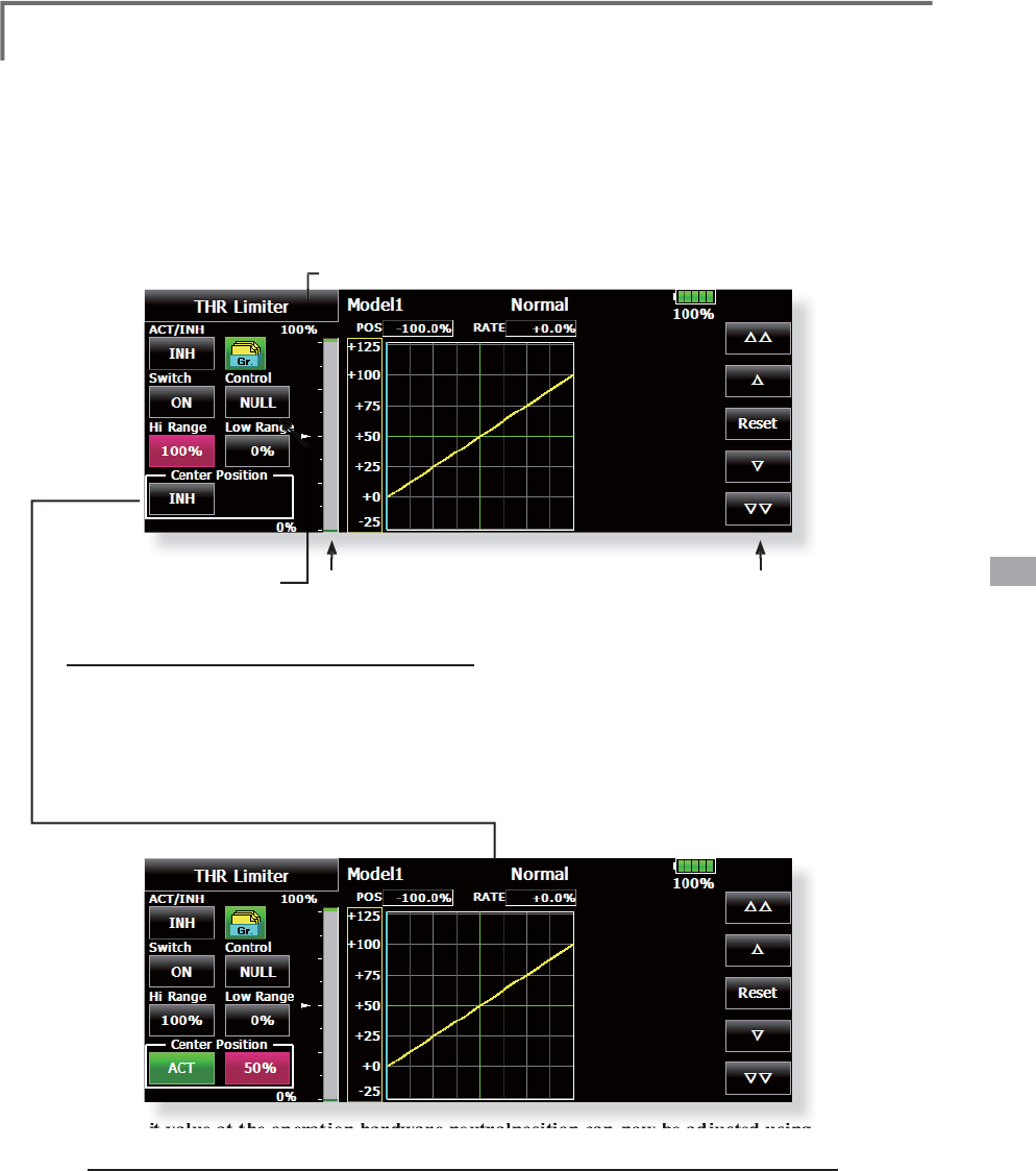
151
<Model Menu (Helicopter Functions)>
Throttle Limiter
This function limits the hi
g
h ran
g
e of the
t
h
rott
l
e movement
b
y any s
lid
er or tr
i
mmer. T
h
e
adj
ustment ran
g
e of t
h
e
high
an
d
l
ow en
d
can
b
e
set.
ŏ5HWXUQWR0R
G
H
O
0HQ
X
ŏ
7RXFKWKH
>
7KURWWOH/LPLWHU
@
EXWWRQRIWKH
0
RGHO0HQXWRFDOOWKHVHWX
S
VFUHHQVKRZQ
EH
O
R
Z
S
ett
i
ng method
ŏ$FW
L
YDWHWKHP
L
[
L
QJDQGVHOHFWWKHRQR
II
VZ
L
WFK
ŏ6HOHFWWKHFRQWURO
I
RUDG
M
XVWPHQWR
I
WKHK
L
JKO
L
P
L
W
ŏ6HWWKHKLJKUDQJH7KHUDQJHJDXJHVKRZVWKH
V
HWWLQJSRVLWLRQ
ŏ6HWWKHORZUDQJHVDPHDVKLJKUDQJHVHWWLQJ
The limit value at the operation hardware neutralposition can now be adjusted using the
t
hrottlel
i
m
i
ter.
6HW´&HQWHU
S
RV
L
W
L
RQµRQWKHWKURWWOHO
L
P
L
WHUVFUHHQWR2
S
HUDWH
:KHQWKH´&HQWHUSRV
L
W
L
RQµUDWH
L
VFKDQ
J
HGWKHO
L
P
L
WYDOXHDWWKHRSHUDW
L
RQKDUGZDUH
QHXWUDOSRV
L
W
L
RQFDQEHDG
M
XVWHG
ŏ
7KHO
L
P
L
WYDOXHDWWKHR
S
HUDW
L
RQKDUGZDUHQHXWUDO
S
RV
L
W
L
RQZKHQ´&HQWHU
S
RV
L
W
L
RQµZDV
F
KDQJHGWR,1+DWFRQYHQWLRQDORSHUDWLRQLVWKHFHQWHUYDOXHEHWZHHQ´+LJKVLGHUDQJHµ
DQG´/RZVLGHUDQJHµ
ŏ
:KHQ´&HQWHU
S
RVLWLRQµZDVVZLWFKHGIURP,1+WR2
S
HUDWHWKH´&HQWHU
S
RVLWLRQµUDWHLVUHVHW
W
RWKHFHQWHUYDOXHEHWZHHQ´+L
J
KVLGHUDQ
J
HµDQG´/RZVLGHUDQ
J
H
µ
ŏ
7KH´&HQWHUSRVLWLRQµUDWHFDQEHVHWEHWZHHQ´+L
J
KVLGHUDQ
J
HµDQG´/RZVLGHUDQ
J
Hµ
5
DQ
J
H
J
DX
J
H
5
DWHDG
M
XVWEXWWRQ
&
RQWUROVHOHFWLRQ
EX
WW
R
Q
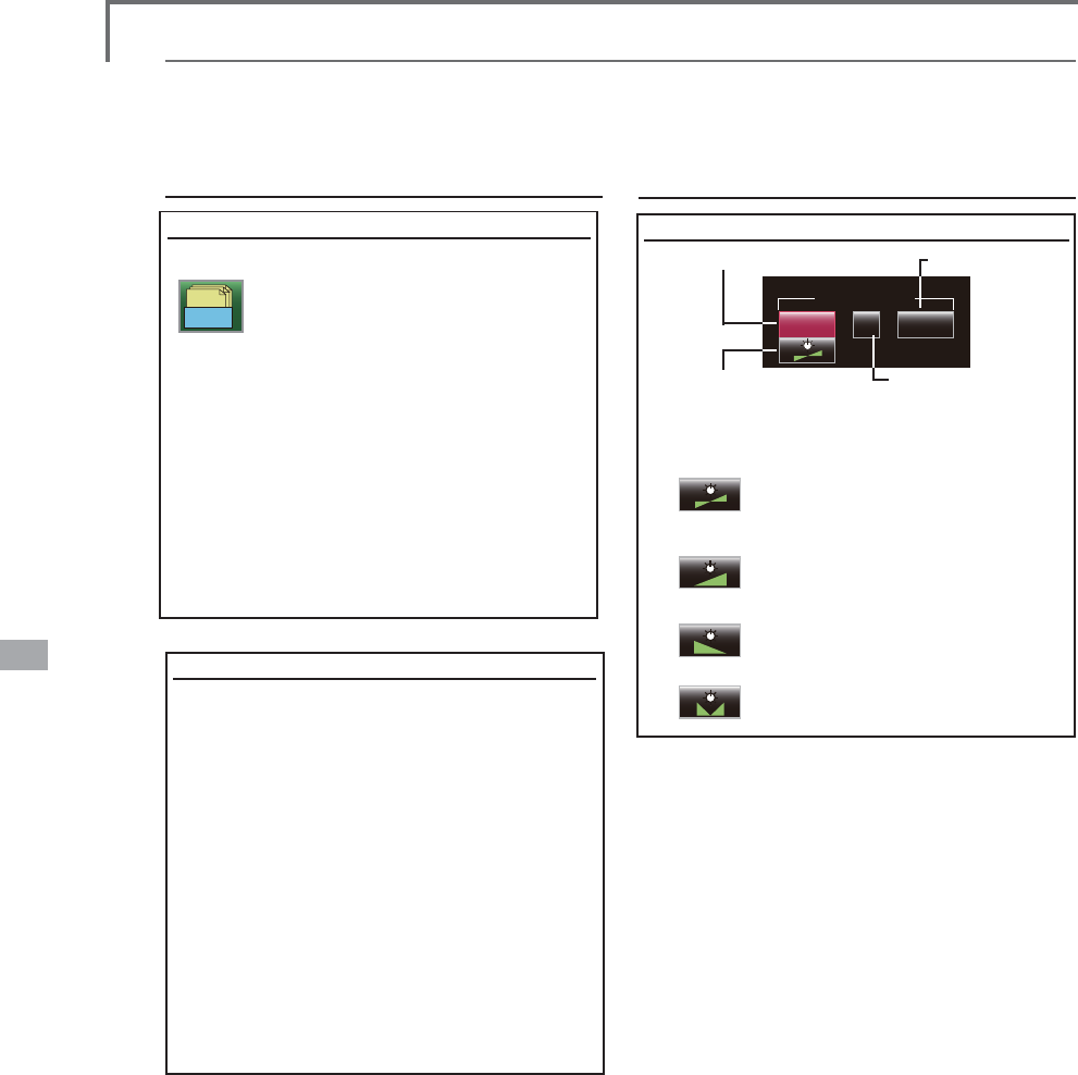
152 <Data>
Fine Tuning
LD 0%
+
( +0%)
Fine tuning VR setting
Mixing rate 0% at center of VR
When the VR is turned counterclockwise
and clockwise, the mixing rate increases
and decreases, respectively.
Mixing rate 0% at left end of VR
When the VR is turned, the mixing rate
increases.
Mixing rate 0% at right end of VR.
When the VR is turned, the mixing rate
increases.
When the VR is turned to the left or right
of the neutral position, the mixing rate
increases.
ŏ95VHOHFWLRQ ŏ5DWHDGMXVWPHQW
ŏ2SHUDWLRQPRGHVHOHFWLRQ
*Displayed at VR setting.
ŏ$GMXVWPHQWGLUHFWLRQ
setting
>2SHUDWLRQPRGHV@
Common operations used in function setup screen
This section describes the functions often used at the function setup screen. Refer to it when setting each
function.
Gr.
Group/single mode switching (Gr./Sngl)
When setting multiple flight
conditions, linking the setting contents
with other conditions (Gr.) or setting
independently (Sngl) can be selected.
When the button is touched, it toggles
between Gr. and Sngl.
*Group mode (Gr.) (initial setting): The same
setting contents are set to all the flight
conditions in the group mode.
*Single mode (Sngl): Select this mode when
the setting contents are not linked with
other conditions.
*Selecting the single (Sngl) mode at each
condition after presetting in the group
mode (Gr.) is convenient.
Condition delay setting
Unnecessary fuselage motion generated when
there are sudden changes in the servo position and
variations in the operating time between channels
at condition switching can be suppressed.
When the delay function is set at the switching
destination condition, a delay corresponding to
that amount is applied and the related functions
change smoothly.
>6HWWLQJPHWKRG@
1. Switch to the condition you want to set.
2. Touch the Delay button.
8VHWKHDGMXVWPHQWEXWWRQVWRVHWWKHGHOD\
*Initial value: 0
$GMXVWPHQWUDQJHaPD[LPXPGHOD\
Operations related to VR tuning
2SHUDWLRQVUHODWHGWRÀLJKWFRQGLWLRQV
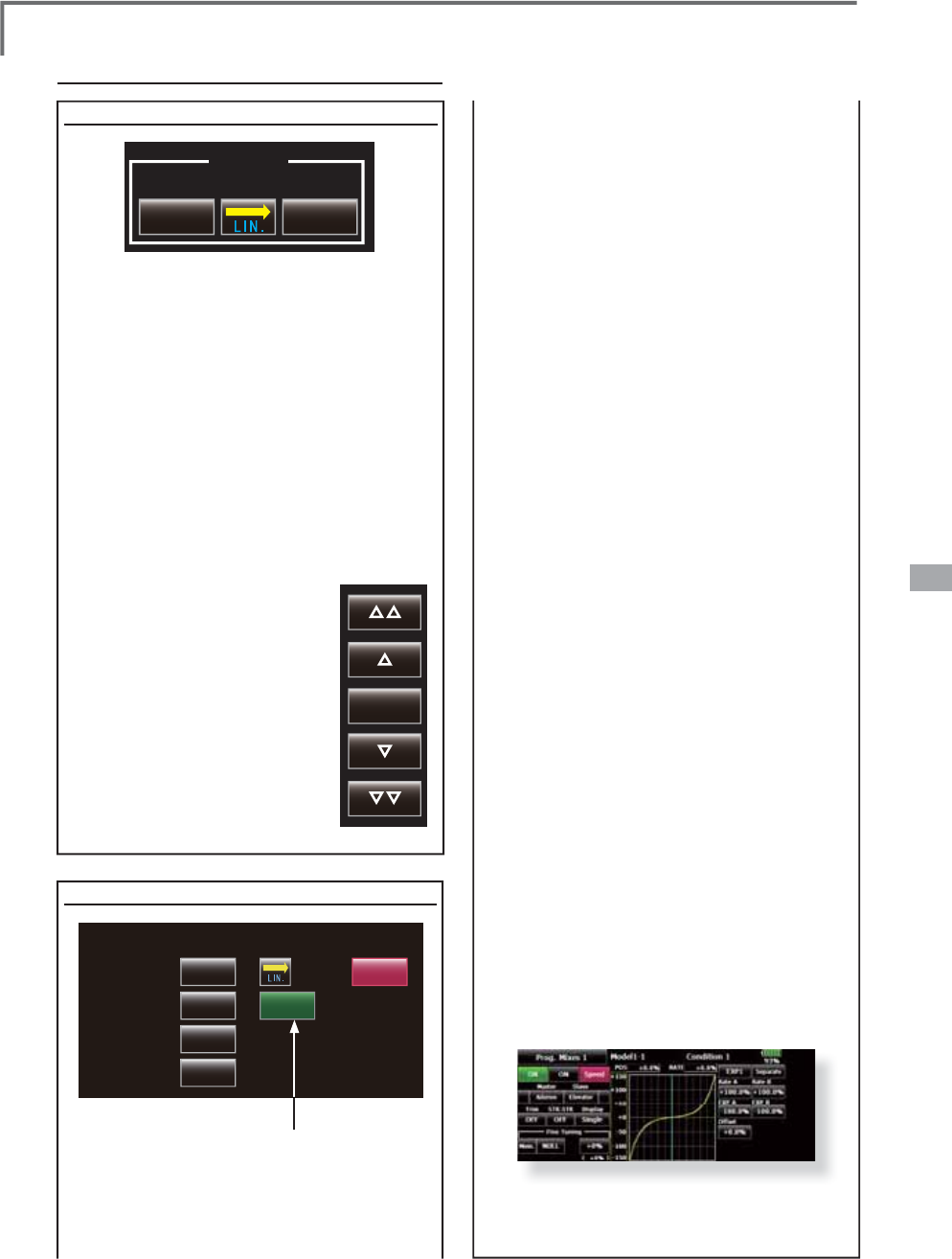
153
<Data>
Servo speed setting (1)
IN
0 0
Speed
OUT
The speed at each operation (includin
g
fli
g
ht
c
on
di
t
i
on sw
i
tc
hi
ng
)
can
b
e a
dj
uste
d
. T
h
e
servos operate smoot
hly
at a constant spee
d
c
orrespondin
g
to the set speed. The operation
spee
d
(
In Spee
d)
an
d
t
h
e return spee
d
(
Out Spee
d)
c
an
b
e set
i
n
di
v
id
ua
lly
.
S
w
i
tc
h
t
h
e operat
i
on mo
d
e accor
di
ng to t
h
e set
function. When the button is touched, it to
gg
les
between [LIN] and [SYM].
"S
YM" mode: Mode used w
i
th a
i
lerons and
o
ther sel
f
-neutral
f
unct
i
on
s
"
LIN" mode
:
Mode used w
i
th
f
unct
i
ons wh
i
ch
h
old the operat
i
on pos
i
t
i
on o
f
the throttle
a
nd sw
i
tch channel, etc
.
>
6HWWLQJPHWKRG@
6HOHFWWKH
I
XQFW
L
RQ
>/,1@R
U
>
6<0@
PDWFKHGWRWKHPDVWH
U
c
hannel. Each t
i
me the
b
utton
i
s touched,
i
t toggles
E
HWZHHQ
>
/,1
@
DQG
>
6<0
@
7RXFKWKH,QRU2XW6SHHG
b
utton an
d
set the servo
s
peed
.
I
nitial value:
0
6
HWWLQJUDQJHa
O
p
erations related to servo s
p
eed
speed correspond
i
ng to the set speed
.
Master mode: The servo movement
i
s
traced by the sett
i
ng curve. The trace
VSHHG
L
VDG
M
XVWHGE\
L
QDQGRXWVSHHG
>6HWW
L
QJPHWKRG
@
1. When sett
i
ng the servo speed, touch the
S
pee
d
b
utton. T
h
e
S
ervo
S
pee
d
setup
screen shown above
i
s d
i
splayed
.
6HOHFWWKH
I
XQFW
L
RQ
>/,1@RU>6<0@
PDWFKHG
to the master channel. Each t
i
me the
EXWWRQ
L
VWRXFKHG
L
WWRJJOHVEHWZHHQ>/,1@
DQ
G
>6
<0
@
"SYM" mode: Mode used w
i
th a
i
lerons and
other sel
f
-neutral
f
unct
i
ons
.
"LIN" mode: Mode used w
i
th
f
unct
i
ons
wh
i
ch hold the operat
i
ng pos
i
t
i
on o
f
the
throttle and sw
i
tch channel, etc
.
3
. Touc
h
t
h
e In
S
pee
d
b
utton an
d
set t
h
e
servo spee
d.
In
i
t
i
al value:
0
6HWW
L
QJUDQJHa
7RXF
K
W
K
H
2
XW
6
SHH
G
E
XWWRQDQ
G
VHWW
K
H
servo spee
d.
In
i
t
i
al sett
i
ng:
0
6HWW
L
QJUDQJHa
5. Touc
h
t
h
e
S
tart De
l
ay
b
utton an
d
set t
h
e
GHOD\W
L
PH
I
URPVZ
L
WFK21WRWKHVWDUWR
I
f
unct
i
on operat
i
on
.
In
i
t
i
al sett
i
ng: 0.0 se
c
6HWW
L
QJUDQJHaVHF
V
6
. Touc
h
t
h
e
S
top De
l
ay
b
utton an
d
set t
h
e
GHOD\W
L
PH
I
URPVZ
L
WFK2))WRWKHVWDUWR
I
f
unct
i
on operat
i
on
.
In
i
t
i
al sett
i
ng:
0
6HWW
L
QJUDQJHaVHF
V
$WPDVWHUPR
G
H
1. Set des
i
red
i
n and out speed
.
2
.
S
e
l
ect t
h
e master c
h
anne
l
to any togg
l
e
sw
i
tch
.
3. The slave channel's servo traces the sett
i
ng
curve as the master toggle sw
i
tch
i
s moved.
%H
O
RZW
K
HFDVH$8;VHUYRWUDFHVDQ(;3
FXUYHDVWKH6:)
L
VRSHUDWHG
Reset
Servo speed settin
g
(2) (Pro
g
. Mix onl
y
)
Servo Speed
In Speed
Out Speed
Start Delay
Stop Delay
0Close
0Slave
ۢ
ۢ
S
pee
d
mo
d
e:
Sl
ave
/
Maste
r
The speed mode can be selected.
Slave mode: The speed at pro
g
rammable
PL[LQ
J
VZLWFKLQ
J
FDQEHDG
M
XVWHG7KH
servos o
p
erate smoothl
y
at a constant
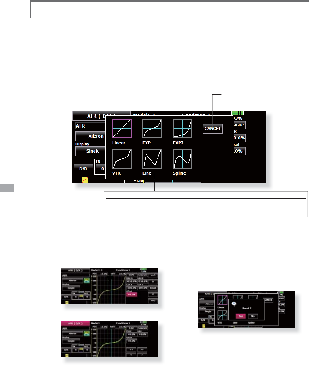
154 <Data>
C
urve settin
g
operation
T
hi
s sect
i
on
d
escr
ib
es t
h
e sett
i
ng proce
d
ure of curves w
hi
c
h
are use
d
w
i
t
h
t
h
e AFR funct
i
on an
d
eac
h
m
ixin
g
function.
Curve type selection
When the curve type select button on the mixing function screen or other screen is touched, the setup
sc
r
ee
n
show
n
below
is
c
a
lled.
ŏ
5HWXUQWRRU
L
J
L
QDOVHWXSVFUHHQ
of
or
i
g
i
nal
f
unct
i
o
n
C
urve t
y
pe select
i
on
1
. Touch the button of the curve t
yp
e
y
ou want to use
.
*The curve type chan
g
es and the display returns to the ori
g
inal screen.
retr
i
eve
d
from t
h
e prev
i
ous sett
i
ng
d
ata w
h
en
ch
an
gi
n
g
t
h
e curve t
y
pe.
A
t t
h
e curve type c
h
anges, t
h
e
di
a
l
ogue
b
ox as
k
s w
h
et
h
er t
h
e current curve
i
s reset or
inherited. The default curve is used when selecting
WK
H<HV
E
XWWRQRQW
K
HFRQ
¿
UPDW
L
RQ
GL
D
O
RJXH
W
hen curve type
i
s changed:
Th
e curve s
h
ape
i
s
i
n
h
er
i
te
d
w
h
en t
h
e curve
t
y
pe
i
s c
h
an
g
e
d
.
([DPSOH&KDQ
J
HVIURP(;3WR/LQHFXUYHW\SH
Changed to line or spline mode, the curve is
r
etr
i
eve
d
as 17 po
i
nts curve.
Th
e
Rat
e
A an
d
Rat
e
B ar
e
inh
e
rit
ed
o
n th
e
li
near
,
EXP1
,
EXP2 an
d
VTR.
Ot
h
er
d
ata except Rate A an
d
Rate B are
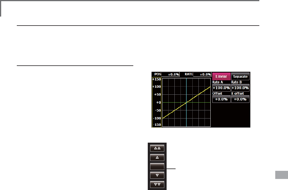
155
<Data>
Reset
Linear curve adjustment
Rate A and Rate B can be adjusted separately or
simultaneously.
>6HWWLQJPRGHV@
*[Separate] mode:5DWHVDUHDGMXVWHG
separately.
*[Combined] mode:5DWHVDUHDGMXVWHG
simultaneously.
>6HWWLQJPHWKRG@
1. Select the setting mode.
7RXFKWKH5DWH$RU5DWH%EXWWRQ
8VHWKHDGMXVWPHQWEXWWRQVWRVHWWKHUDWH
*Initial value: +100.0%
$GMXVWPHQWUDQJHa
The curve can also be offset horizontally in the
vertical direction and the rate reference point can
be offset to the left or right.
>2IIVHWWLQJWKHFXUYHKRUL]RQWDOO\LQWKHYHUWLFDO
GLUHFWLRQ@
7RXFKWKH2IIVHWEXWWRQ
8VHWKHDGMXVWPHQWEXWWRQVWRPRYHWKH
FXUYHKRUL]RQWDOO\XSDQGGRZQ
*Initial value: +0.0%
>2IIVHWWLQJWKHUDWHUHIHUHQFH
SRLQWWRWKHOHIWRUULJKW@
7RXFKWKH;2IIVHWEXWWRQ
8VHWKHDGMXVWPHQWEXWWRQVWR
move the reference point to the
left or right.
*Initial value: +0.0%
Setting by curve type
When the curve type is selected as described above, adjustment buttons corresponding to the curve type
appear on the original screen. Adjust each curve as described below.
(Linear curve)
5DWHDGMXVWPHQWEXWWRQV
ŏ5HWXUQWRLQLWLDOYDOXH
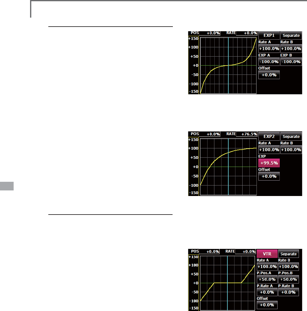
156 <Data>
EXP1 curve adjustment
Rate A and Rate B can be adjusted separately
or simultaneously. The EXP curves rate (EXP
A, EXP B) can also be adjusted separately or
simultaneously.
>6HWWLQJPRGHV@
*[Separate] mode:5DWHVDUHDGMXVWHG
separately.
*[Combined] mode:5DWHVDUHDGMXVWHG
simultaneously.
>6HWWLQJPHWKRG@
1. Select the setting mode.
7RXFKWKHEXWWRQRIWKHUDWHRU(;3FXUYH
rate your want to set.
8VHWKHDGMXVWPHQWEXWWRQVWRVHWWKHUDWH
,QLWLDOYDOXHUDWH(;3UDWH
The curve can also be horizontally offset in the
vertical direction.
>2IIVHWWLQJWKHFXUYHKRUL]RQWDOO\LQWKHYHUWLFDO
GLUHFWLRQ@
7RXFKWKH2IIVHWEXWWRQ
8VHWKHDGMXVWPHQWEXWWRQVWRPRYHWKH
FXUYHKRUL]RQWDOO\XSRUGRZQ
*Initial value: +0.0
(;3FXUYH
ŏ8VLQJWKH(;3FXUYHLVKHOSIXOLQ
smoothening starting of the ailerons,
elevators, rudder, etc.
(;3FXUYH
ŏ8VLQJWKH(;3FXUYHLVKHOSIXOLQHQJLQH
rise and other engine control.
VTR curve adjustment
Rate A and Rate B can be adjusted separately or
simultaneously. The VTR curve point positions (P.
Pos. A, P. Pos. B) and rates (P. Rate A, P. Rate B)
can also be adjusted separately or simultaneously.
>6HWWLQJPRGHV@
*[Separate] mode:3RVLWLRQVDQG UDWHVDUH
DGMXVWHGVHSDUDWHO\
*[Combined] mode:3RVLWLRQVDQGUDWHVDUH
DGMXVWHGVLPXOWDQHRXVO\
>6HWWLQJPHWKRG@
1. Select the setting mode.
2. Touch the button of the rate or VTR curve
point position (or rate) you want to set.
8VHWKHDGMXVWPHQWEXWWRQVWRVHWWKH975
curve point position (or rate).
,QLWLDOYDOXHV5DWH33RV$
33RV%35DWH
The curve can also be offset horizontally in the
vertical direction.
>2IIVHWWLQJWKHFXUYHKRUL]RQWDOO\LQWKHYHUWLFDO
GLUHFWLRQ@
7RXFKWKH2IIVHWEXWWRQ
8VHWKHDGMXVWPHQWEXWWRQVWRPRYHWKH
FXUYHKRUL]RQWDOO\XSDQGGRZQZLWKWKH
DGMXVWPHQWEXWWRQV
*Initial value: +0.0%
(VTR curve)
ŏ6HWWLQJLVIDVWLIOHIWULJKWXSDQGGRZQ
DUHÀUVWGHFLGHGLQWKH&RPELQHGPRGH
and the mode is then switched to the
Separate mode.
When this curve is used when the
operating rudder angle is large such as
with acrobatic models, switching from
QRUPDOÁLJKWWRDFUREDWLFUXGGHUDQJOHLV
performed without switch operation.
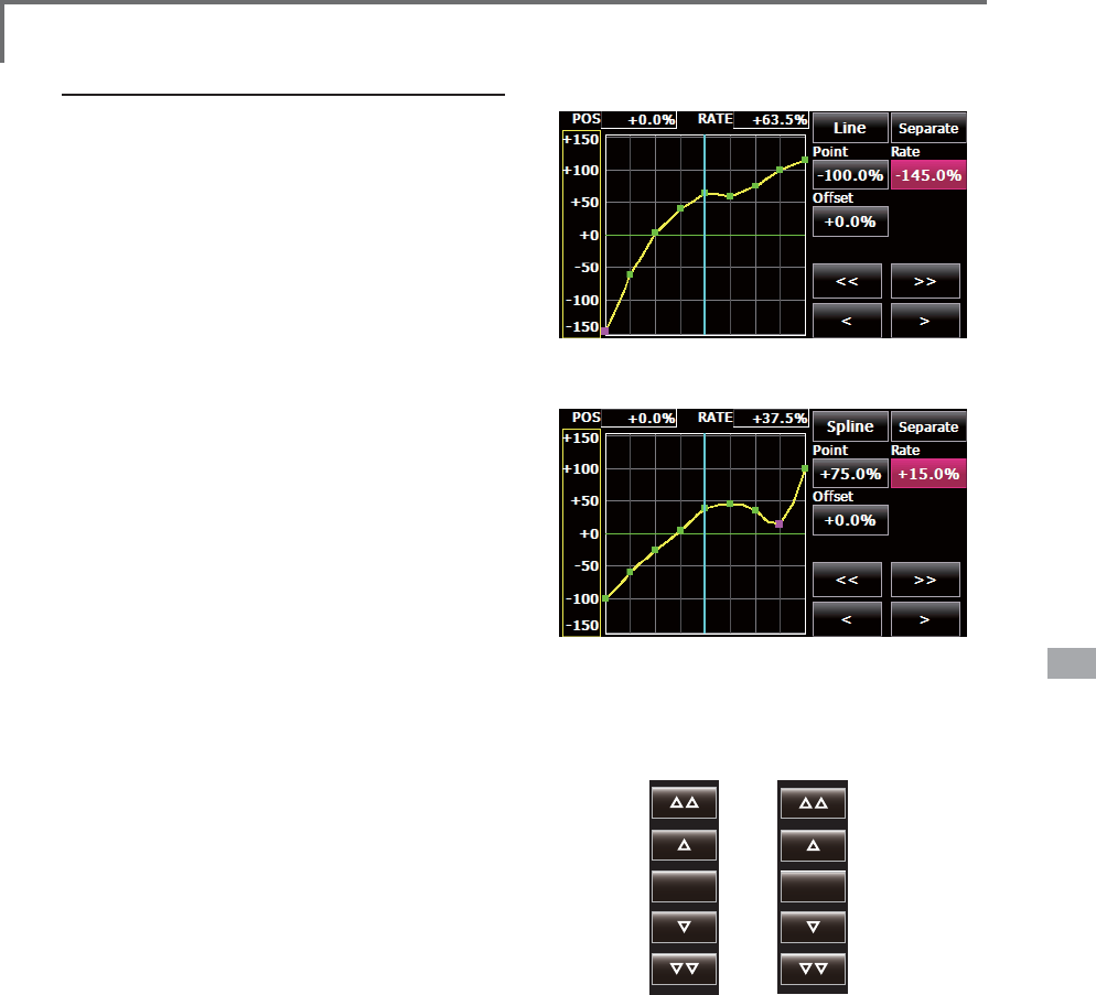
157
<Data>
Move Delete
Line and spline curve adjustment
Line curves or spline curves of up to 17 points
can be used. (Initial value: 7/9 points) The set
points can be freely increased, decreased, and
offset. Curves which are symmetrical to the left and
right of center can also be set.
>6HWWLQJPRGHV@
*[Separate] mode: Normal setting
*[Combined] mode: Creates a left and right
symmetrical curve.
>$GMXVWLQJWKHUDWHRIHDFKSRLQW@
8VHWKHPRYHEHWZHHQSRLQWVEXWWRQV>@
RU>!!@WRVHOHFWWKHSRLQW7KHSLQNSRLQWLV
the selected point.)
2. Touch the Rate button.
8VHWKHDGMXVWPHQWEXWWRQVWRDGMXVWWKH
rate.
[Point addition method]
$IWHUWRXFKLQJWKHSRLQWEXWWRQPRYHWKH
stick, etc. to the point you want to add and
SUHVVWKH>0RYH@EXWWRQ$QRXWOLQHGSRLQW
appears on the graph.)
2UPRYHWKHVWLFNHWFWRWKHSRVLWLRQ\RXZDQW
WRDGGDQGSUHVVWKH>0RYH@EXWWRQ$Q
outlined point appears on the graph.)
8VHWKHPRYHEXWWRQV>@RU>!@WRILQH
DGMXVWWKHSRVLWLRQ
3. Touch the Insert button.
$QHZSRLQWLVFUHDWHG
[Point deletion]
8VHWKHPRYHEHWZHHQSRLQWVEXWWRQ>@
RU>!!@DQGVHOHFWWKHSRLQW7KHSLQNSRLQW
is the selected point.)
7RXFKWKH>'HOHWH@EXWWRQ7KHVHOHFWHG
point becomes an outlined point.)
7RXFKWKHPRYHEHWZHHQSRLQWEXWWRQ>@
RU>!!@
*The point is deleted.
The curve can also be offset horizontally in the
vertical direction.
>2IIVHWWLQJWKHFXUYHKRUL]RQWDOO\LQWKHYHUWLFDO
GLUHFWLRQ@
7RXFKWKH2IIVHWEXWWRQ
8VHWKHDGMXVWPHQWEXWWRQVWRPRYHWKH
FXUYHKRUL]RQWDOO\XSDQGGRZQ
*Initial value: +0.0%
(Line curve)
(Spline curve)
5DWHDGMXVWPHQWEXWWRQV
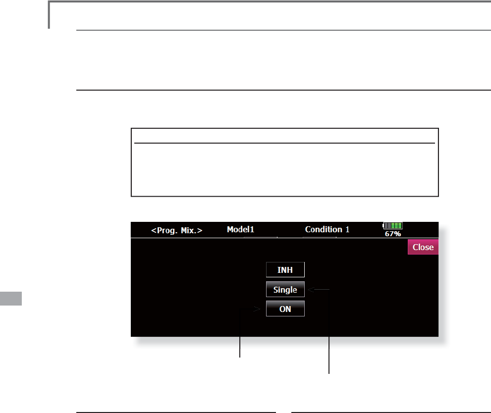
158 <Data>
S
w
i
tch select
i
on method
The various functions used in the T14MZ can be selected b
y
switch. The switch (includin
g
when stick,
tr
i
m
l
ever, or VR are use
d
as a sw
i
tc
h)
sett
i
ng met
h
o
d
i
s common to a
ll
funct
i
ons.
S
w
i
tch mode select
i
on
(Si
n
g
le sw
i
tch
/
Lo
gi
c sw
i
tch
)
Wh
en t
h
e sw
i
tc
h
se
l
ect
b
utton at a m
i
x
i
n
g
funct
i
on screen or ot
h
er screen
i
s touc
h
e
d
, t
h
e sw
i
tc
h
mo
d
e
selection screen shown below is called. Sin
g
le switch mode or lo
g
ic switch mode can be selected.
(
Sw
i
tch mode select
i
on screen example
)
Log
i
c sw
i
tch
T
h
e Log
i
c sw
i
tc
h
can act
i
vate funct
i
ons
b
y some sw
i
tc
h
es com
bi
nat
i
on.
Can be set up to 4 switch combinations. The Lo
g
ic switch can be assi
g
ned to
W
KHPL[LQJIXQFWLRQDVZHOODVWKHÀLJKWFRQGLWLRQVHOHFWH[FHSWIRU6QDSUROO
funct
i
on on a
i
rp
l
ane mo
d
e
)
.
ŏ
0RGHVHOHFWLRQEXWWRQ
ŏ
6Z
L
WFKVHOHFW
L
RQEXWWRQ
,QFDVHRIW
K
H
ÀL
J
K
WFRQ
GL
W
L
RQVH
O
HFWW
K
HWRSRI
t
h
e sw
i
tc
h
on
/
off status
di
sp
l
ay
i
s not s
h
own
.
If using the single switch:
3XVKWKHVZ
L
WFKVHOHFW
L
RQEXWWRQ
*
T
h
e sw
i
tc
h
se
l
ect
i
on screen appears.
*For a descri
p
tion of the switch selection method, see the sectio
n
"
S
witch selection" below.
If using the logic switch:
1.The sw
i
tch mode d
i
splay
i
s changed by
SXVK
L
QJWKHPRGHVHOHFW
L
RQEXWWRQ$QGWKHQ
SXV
K
W
K
H
>
<HV
@
E
XWWRQ
*
T
h
e
l
og
i
c mo
d
e sett
i
ng screen appears
.
*For a description of the lo
g
ic mode settin
g
method, see the
s
ection "Lo
g
ic switch" below.
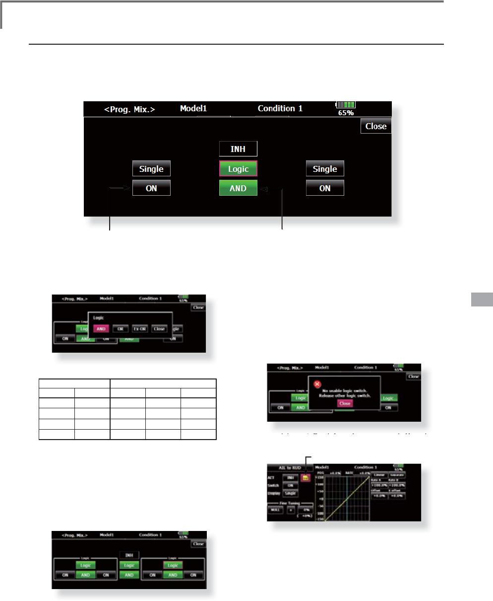
159
<Data>
Log
i
c sw
i
tch
A
t t
h
e
l
og
i
c sw
i
tc
h
mo
d
e, t
h
e sw
i
tc
h
se
l
ect
i
on
b
uttons appear on
b
ot
h
t
h
e
l
eft an
d
r
i
g
h
t s
id
e of t
h
e
di
sp
l
a
y
.
(
Log
i
c sw
i
tch sett
i
ng screen
)
ŏ/RJ
L
FPRGHEXWWR
Q
1.The log
i
c select
i
on d
i
alogue appears when
you push the log
i
c mode button. The 3 types
R
I
ORJ
L
FH
L
WKHU$1'25RU(;25FDQEH
se
l
ecte
d.
L
og
i
c comb
i
nat
i
on table
:
SWITC
H
/2*,
&
S
W
1
SW
2
$1' 2
5
([2
5
o
f
f
o
ff
o
ff
o
ff
o
f
f
off
on
off
on
on
o
n
o
ff
o
ff
o
n
o
n
on
on
on
on
off
2
. The le
f
t and r
i
ght s
i
de o
f
the sw
i
tch mode
c
an be set to the log
i
c sw
i
tch mode as well.
I
n th
i
s case, a max
i
mum o
f
4 sw
i
tches can
b
e ass
i
gned to the log
i
c sw
i
tch. The le
f
t and
UL
JKWORJ
L
FDUHFDOXODWHG
À
UVWWKHQWKHFHQWHU
RI
WKHORJ
L
F
L
VFDOFXODWHG)
L
QDOO\VZ
L
WFKRQ
off
status determ
i
ned by the 4 sw
i
tches'
c
omb
i
nat
i
on
.
I
n the above case, the two sw
i
tches
i
n the
O
H
I
WDUHFDOFXODWHGE\$1'OR
JL
F1H[WWKH
t
wo sw
i
tches
i
n the r
ig
ht are calculated as
V
DPHZD
\
)
L
QDOO
\
WKH
À
UVWFDVHDQGQGFDVH
D
UHFDOFXODWHGE\25OR
JL
F
C
aut
i
on
:
7KHPD[LPXPQXPEHURIWKHOR
J
LFVZLWFKLVIRUWKHÀL
J
K
W
condition select and 8 for the mixin
g
on/off selection on eac
h
fli
g
ht condition. The error messa
g
e will appear when the
exceeded lo
g
ic switch is
g
oin
g
to be selected. In this case,
G
HOHWHWKHXQXVHGOR
J
LFVZLWFK¿UVWWKHQVHOHFWWKHQHZOR
J
LF
s
witch.
2. The mixing on/off switch modes are automatically assigned
by
s
i
n
gl
e mo
d
e, not supporte
d
t
h
e
g
roup mo
d
e.
Assigned to single mode
ŏ
6
ZLWFKVHOHFWLRQEXWWR
Q
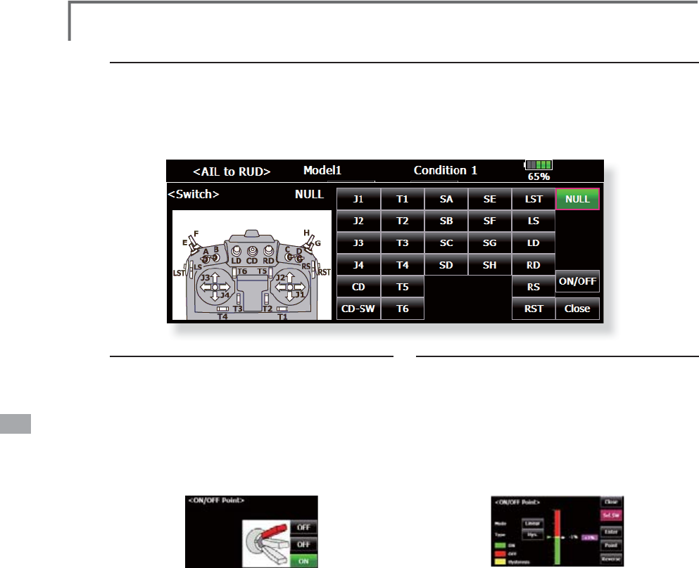
160 <Data>
S
w
i
tch select
i
on
Wh
en t
h
e sw
i
tc
h
se
l
ect
i
on
b
utton at t
h
e sw
i
tc
h
mo
d
e se
l
ect
i
on screen or t
h
e
l
og
i
c sw
i
tc
h
sett
i
ng screen
i
s
touc
h
e
d
, t
h
e se
l
ect
i
on screen s
h
own
b
e
l
ow
i
s ca
ll
e
d
.
(
Sw
i
tch select
i
on screen example
)
W
hen switch is selected
Switch ON/OFF settin
g
is possible at each
p
osition.
ŏ
Alt
e
rn
a
t
e:
$OWHUQDWHVZLWFKLQ
J
PRGHLV
available dependin
g
on mixin
g
function
.
:KHQWKH21
S
RVLWLRQVZLWFKLVWRXFKHGDIWHU
the switch was selected
,
the screen shown
below a
pp
ears
.
*When the button o
f
each pos
i
t
i
on
i
s touched,
LWWRJJOHVEHWZHHQ21DQG2))
7RXFKWKHEXWWRQDQGVHWWRWKH21SRV
L
W
L
RQ
&ORVHWKHVFUHHQE\WRXFK
L
QJ>&ORVH@
When stick, trim lever, or VR is selected.
W
hen a stick, trim lever, or VR is used as a
switch, the following 4 modes can be selected.
ŏ
M
ode:
Lin/S
ym
ŏ
T
yp
e
:
Hysteresis
(
Hys.
)
/box
(
Box
)
:KHQWKH21
S
RVLWLRQEXWWRQLVWRXFKHGDIWHU
s
tick
,
etc. was selected
,
the screen shown
below a
pp
ears
.
2
. Select the mode you want to use, and set it
as descr
i
bed below
.
&ORVHWKHVFUHHQE\WRXFKLQJ>&ORVH@
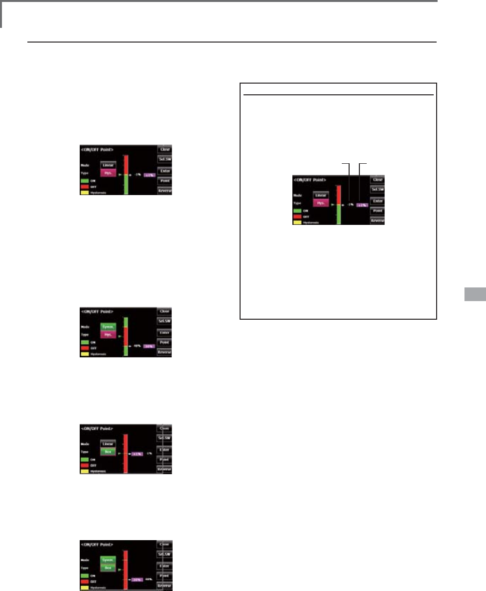
161
<Data>
Operation modes
The operation modes when stick, trim lever or VR are selected are described below. Change the
operation mode by touching the Mode and Type buttons.
Linear hysteresis mode
This setting method selects function ON/OFF
based on the set point. Hysteresis (dead band) can
be set between ON and OFF. The ON and OFF
positions can be reversed with the Reverse button.
Symmetrical hysteresis mode
Operation is the same as the linear hysteresis
mode, but left and right (up and down) operations
are symmetrical about the neutral position. For
example, when you want to switch DR1 with the
aileron stick, when the stick is moved to the left or
right, DR1 can be turned ON at the same left and
right position.
Linear box mode
This mode turns on the switch within a range of
2 points. Each point can be set. The ON and OFF
positions can be reversed with the Reverse switch.
Symmetrical box mode
Operation is the same as the linear box mode,
but left and right (up and down) operation is
symmetrical about the neutral position.
When shifting the ON/OFF point
The ON/OFF and hysteresis (dead band)
boundary point (there are 2 points: top and
bottom) position can be shifted. ON/OFF is
possible at a free position.
>6HWWLQJPHWKRG@
1. Select the top and bottom boundary points
ZLWKWKH>3RLQW@EXWWRQ
2. Move the stick, etc. to the point you want
WRVKLIWDQGWRXFKWKH>(QWHU@EXWWRQ7KH
boundary points change.
$OVRVKLIWRWKHUSRLQWVDVUHTXLUHG
Top point Bottom point
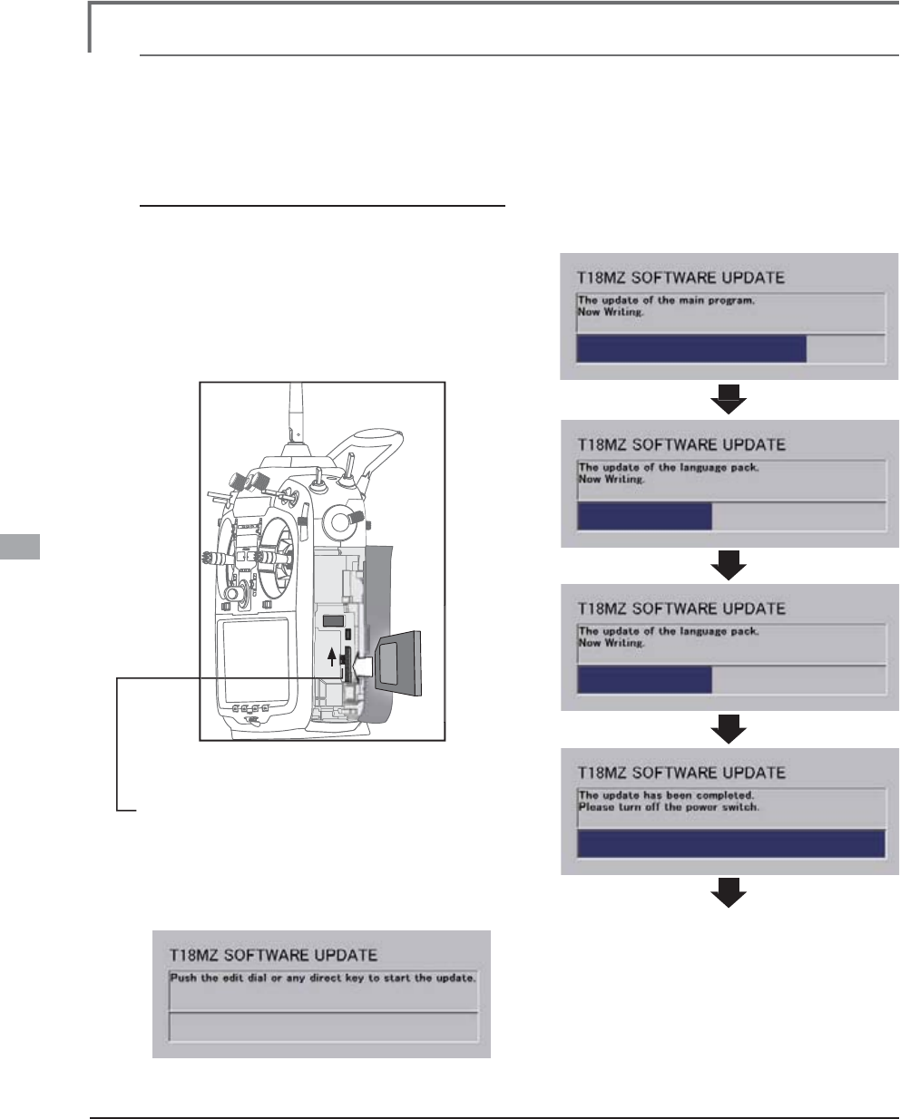
162 <Data>
Updat
i
ng
70=WUDQVPLWWHUSUR
J
UDPFDQEHXSGDWHG:KHQIXQFWLRQVDUHDGGHGRULPSURYHGWKHXSGDWH¿OHFDQ
E
H
G
RZQ
O
RD
G
H
G
IURPRXUZH
E
V
L
WH&RS\W
K
HXS
G
DWH
¿O
HVWRW
K
H6'FDU
G
DQ
G
W
K
HQXVHW
K
HIR
OO
RZ
L
QJSURFH
G
XUH
to update the pro
g
ram.
Updat
i
ng procedure
N
ote: I
f
the battery
f
ully d
i
scharges dur
i
ng
p
rogram updat
i
ng, updat
i
ng w
i
ll
f
a
i
l. When
t
he remaining battery capacity is 50
%
or
l
ess, always recharge the battery be
f
ore
u
pdat
i
ng
.
N
ote: The model data
i
n the transm
i
tter can
b
e used unchanged a
f
ter updat
i
ng, but to
b
e sa
f
e, back up the model data be
f
ore
u
pdat
i
ng
.
,QVHUWWKH6'FDUGFRQWDLQLQ
J
WKHXSGDWHÀOH
i
nt
o
th
e
ca
r
d
s
l
o
t
.
8
VHWZHH]HUVWRVZLWFKWKHVOLGHVZLWFK
(
update switch
)
at the side of the card slot in
t
he u
p
direction
.
7XUQRQWKHWUDQVPLWWHU
S
RZHU$QX
S
GDWH
s
creen is dis
p
la
y
ed. Rotar
y
ke
y
or the
a
rbitrar
y
direct ke
y
s are
p
ressed
.
4
. When updatin
g
is complete, the screen
s
hown below a
pp
ears
.
7XUQRIIWKH
S
RZHUVZLWFK$IWHUWKHPRQLWRU
L
ED
g
oes off, switch the update switch in the
do
wn
d
ir
ec
ti
o
n
.
If fault happens, an error messa
g
e can come
o
ut and cannot u
p
date
.
$
IWHUWKHXSGDWLQ
J
DERYHKDVEHHQ
c
om
p
leted, turn on the
p
ower and then
c
heck the system pro
g
ram version at the
sy
stem menu information screen
.
FUT
A
B
A
CO
RP
O
R
A
TI
ON
1
080 Yabutsuka, Chosei-mura, Chosei-gun, Chiba-ken, 299-4395, Japa
n
P
h
one: +81 475 32 6982
,
Facs
i
m
il
e: +81 475 32 698
3
2
011, 12
(
1
)