Futaba T18MZ-24G Radio Control User Manual
Futaba Corporation Radio Control
UserManual.wiki
>
Futaba
>
T18MZ-24G User Manual
>
User manual-3(Page 101-162)
Contents
1.
User manual-1(page 1-30)
2.
User manual-2(Page 31-100)
3.
User manual-3(Page 101-162)
User manual-3(Page 101-162)
Navigation menu
Upload a User Manual
Namespaces
Wiki Guide
HTML
PDF
Info
Views
User Manual
Discussion / Help
Navigation
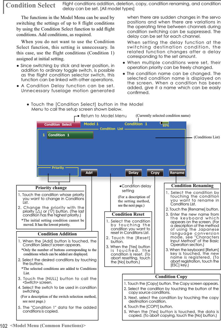
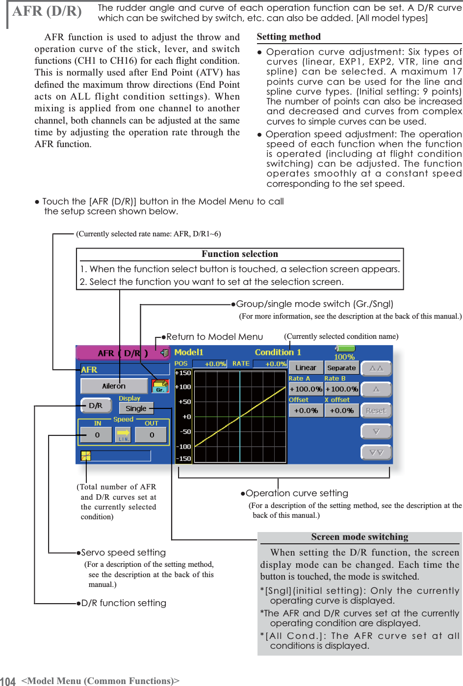
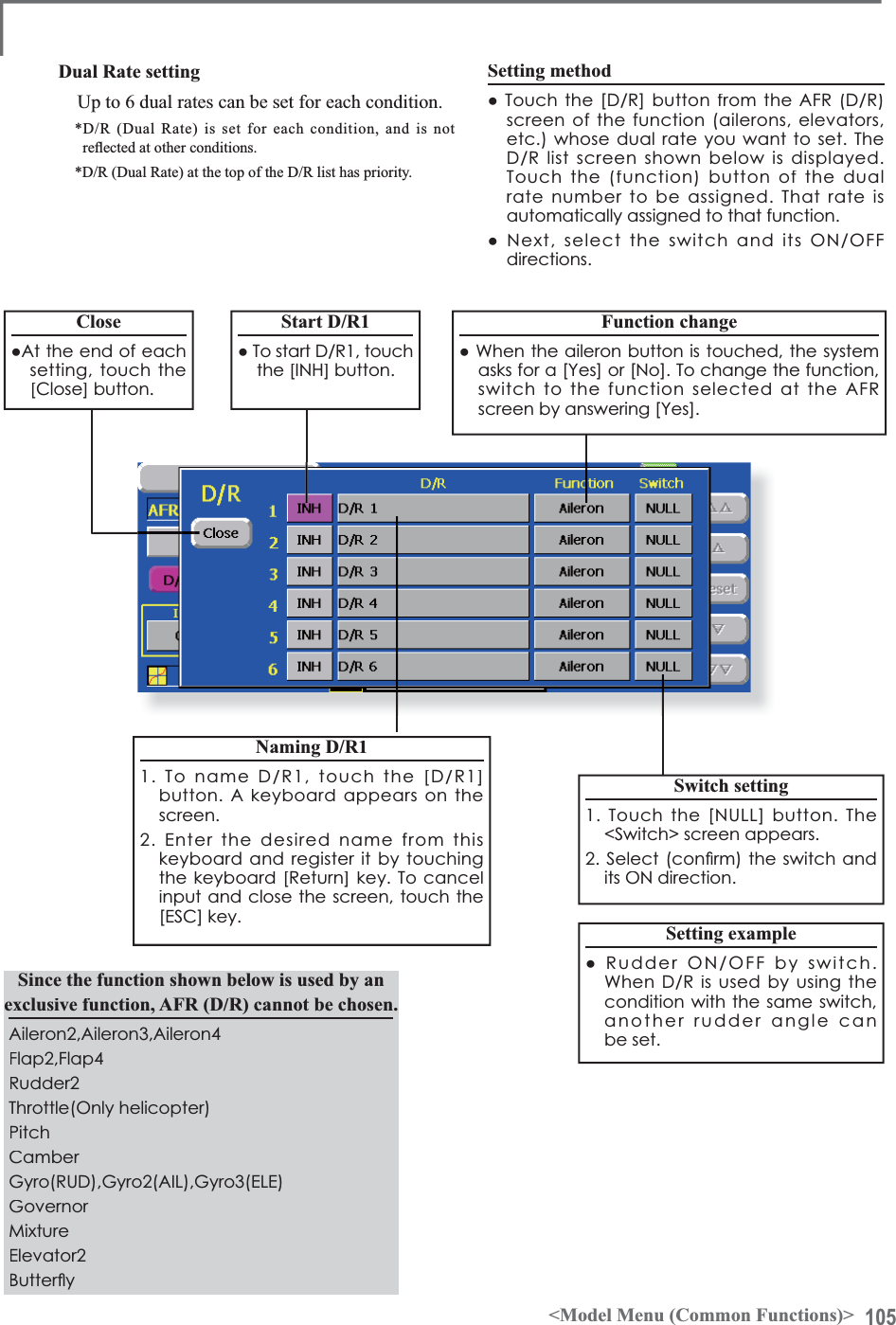
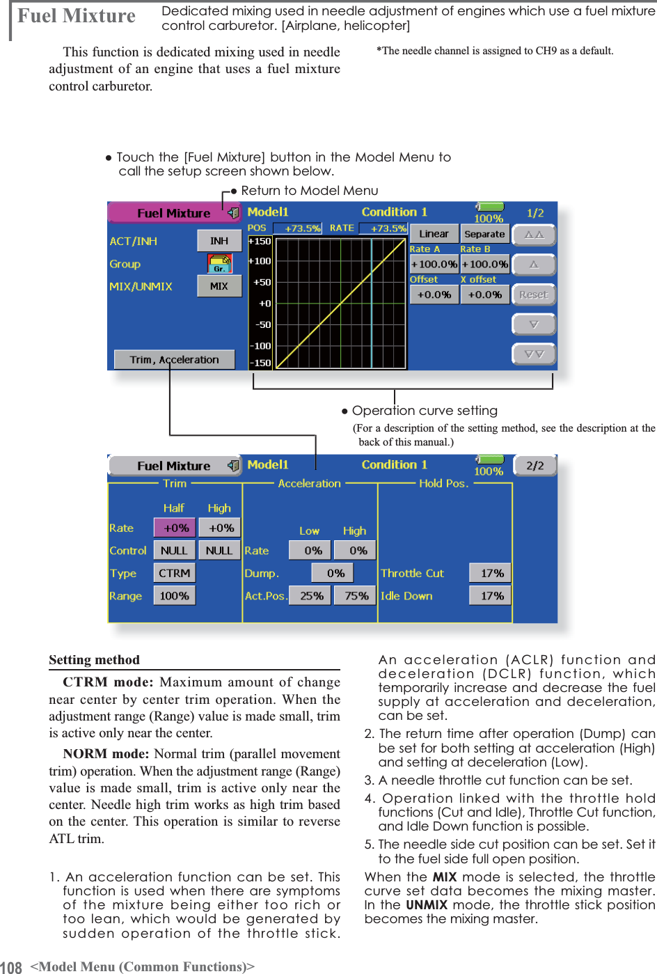
![101<Model Menu (Common Functions)>MODEL MENU (COMMON FUNCTIONS)System Menu Linkage Menu Model Menu ReturnModel 1 Condition 1 85%Model MenuCondition Select AFR ( D/R ) Prog. MixesFlap Setting AIL to CamberFLPAirbrake to ELE ELE to CamberRUD to AIL$,/'LíHUHQWLDOServo MonitorAIL to RUDCamberFLP to ELECamber Mix1/2AIL to Brake FLPRUD to ELE Snap RollThis section describes the AFR, program mixing, and other functions common to all model types.Before setting the model data, use the ModelType function of the Linkage Menu to select the model type matched to the fuselage. When another model type is selected thereafter, the AFR, program mixing, and other setting data are reset.The functions in the Model Menu can be set for each flight condition. When you want to use the system by switching the settings for each condition by switch, stick position, etc., use the Condition Select function to add flight conditions. (Up to 8 conditions can be used)Note: The T18MZ is designed so that the airplane and glider (including EP glider) model types are compatible with fuselages of similar type wings.This section outlines the relationship between the functions common to airplanes and gliders, except some dedicated functions, and model type.The setting items depend on the number of servos and other differences according to the wing type used, but reread them. The setup screens in the instruction manual are typical examples.ŏ5HWXUQWR+RPHVFUHHQŏ7RXFKWKH0RGHO0HQXEXWWRQRIWKH+RPHVFUHHQWRFDOOWKHModel Menu.ŏ:KHQWKHEXWWRQRIWKHIXQFWLRQ\RXZDQWWRVHWLVWRXFKHGDsetup screen appears.(Model Menu screen example)*The Model Menu screen depends on the model type. This screen is for model type 4AIL+4FLP.ŏ7RQH[WSDJHModel Menu functions (Common) listƔ6HUYR0RQLWRUServo test and servo position display (For a description of its functions, see the Linkage Menu section.)Ɣ&RQGLWLRQ6HOHFWFlight conditions addition, deletion, copy,condition renaming, and condition delay can be set. Ɣ$)5'5Sets the rudder angle and curve of all the operation functions. A D/R curve which can be switched with a switch, etc. can also be added.Ɣ3URJ0L[HVProgram mixing which can be freely customized. Up to 10 mixes can be used for each condition.Ɣ)XHO0L[WXUHMixing used in needle adjustment of engines which use a fuel mixture control carburetor. [Airplane, helicopter]](https://usermanual.wiki/Futaba/T18MZ-24G.User-manual-3-Page-101-162/User-Guide-1596944-Page-1.png)
![103<Model Menu (Common Functions)>ŏ5HWXUQWR&RQGLWLRQ6HOHFWVFUHHQŏ7RXFKWKH>'HOD\@EXWWRQRQWKH&RQGLWLRQ6HOHFWVFUHHQWRFDOOWKH&RQGLWLRQ'HOD\screen shown below.(Currently selected condition name)&RQGLWLRQGHOD\VHWWLQJ6ZLWFKWRWKHFRQGLWLRQ\RXZDQWWRVHW7RXFKWKH'HOD\EXWWRQRIWKHFKDQQHO\RXZDQWWRVHW3. Use the adjustment buttons to set the delay.ŏ,QLWLDOYDOXHŏ$GMXVWPHQWUDQJHaPD[LPXPGHOD\ŏ*URXSVLQJOHPRGHVZLWFKLQJ*U6QJO(For a description of the operation method, see thedescription at the back of this manual.)&RQGLWLRQVZLWFKVHWWLQJDQG212))GLUHFWLRQVZLWFKLQJ*For a description of the selection method, see [Switch Setting Method] atthe back of this manual.t](https://usermanual.wiki/Futaba/T18MZ-24G.User-manual-3-Page-101-162/User-Guide-1596944-Page-3.png)
![106 <Model Menu (Common Functions)>ŏ5HWXUQWR0RGHO0HQXŏ7RXFKWKH>3URJ0L[HV@EXWWRQLQWKH0RGHO0HQXWRcall the setup screen shown below.3URJ0L[HV3URJUDPPL[LQJZKLFKFDQEHIUHHO\FXVWRPL]HG8SWRPL[LQJVFDQEHXVHGIRUHDFKFRQGLWLRQ>$OOPRGHOW\SHV@Programmable mixing may be used to correct undesired tendencies of the aircraft, and it may also be XVHGIRUXQXVXDOFRQWUROFRQ¿JXUDWLRQV0L[LQJPHDQVthat the motion of a command channel, called the "master," is added to the motion of the mixed channel, called "slave."You may choose to have the Masters trim added to the Slave channel response, if you desire ("Trim"setting). The mixing curve can be changed so that the undesired tendencies can be corrected effectively by setting the LINEAR1/LINEAR2/EXP1/EXP2/VTR/LINE/SPLINE modes. The Delay function can be programmed for each rate. The Delay is used to change the rate smoothly when switching. You may define Mixing ON/OFF switch, control or you may choose to have mixing remaining on all the time.Offset-type mixing applies a fixed offset or preset to the programmed channel servo operation and may control up to four circuits simultaneously. The Programmable mixing includes a powerful link function, which allows Programmable mixing to be linked with the special mixing functions, or with other programmable mixing functions. The link function can be set up for Master and Slave channel individually.The slave channel AFR mode (STK-STK mode)may be selected, where the slave channel AFR and D/R settings are observed when Link function is set.7KHNQREIRU¿QHWXQLQJFDQEHVHWXSIRUHYHU\PL[LQJcircuit. (Fine tune function)0L[LQJEXWWRQVAfter this function was activated, the master and slave function names (or offset mixing) are displayed.ŏ0L[LQJPRGHFKDQJHEXWWRQŏ*URXSVLQJOHPRGHVZLWFKLQJ*U6QJO(For more information, see the description at the back of this manual.)ŏ2SHUDWLRQFXUYHVHWWLQJŏ6HUYRVSHHGVHWWLQJŏ6ZLWFKVHOHFWLRQŏ)LQHWXQLQJWULPVHWWLQJ(Timer mode)(Normal mode )7LPHUPRGHThe on time (start/stop time) can be set up to 9 seconds. It is useful for landing gear control of the jet or scale plane, etc.(Offset-type mixing) &XUYHW\SHmixing)](https://usermanual.wiki/Futaba/T18MZ-24G.User-manual-3-Page-101-162/User-Guide-1596944-Page-6.png)
![107<Model Menu (Common Functions)>6HWWLQJPHWKRGVŏ*URXSVLQJOHPRGHVHOHFWLRQ$FWLYDWLQJIXQFWLRQVIRURQO\WKHVHOHFWHGconditions:7RXFKWKH*URXSEXWWRQDQGVZLWFKWRWKH6QJOPRGH*Each time the button is touched, it toggles between the Gr. and Sngl modes.ŏ0L[LQJPRGHVHOHFWLRQUsing the offset mode:1. Touch the Mode button and switch to the Offset mode.*Each time the button is touched, it toggles between the Mix and Offset modes.ŏ0L[LQJVHWXSVFUHHQVHOHFWLRQ1. Touch the button of the mixing you want to set. The mixing setup screen is displayed. $FWLYDWHWKHIXQFWLRQ$FWLYDWHWKHIXQFWLRQE\WRXFKLQJWKH>,1+@button.*Each time this button is touched, it toggles between [INH] and [ON/OFF].ŏ0L[LQJ212))VZLWFKVHWWLQJDQG212))direction switching*An ON/OFF switch is not set even when the function is activated.:KHQ\RXZDQWWRWXUQPL[LQJ212))E\VZLWFKWRXFKWKH>18//@EXWWRQWRFDOOWKH6ZLWFK!VFUHHQDQGWKHQVHOHFWWKHVZLWFKand its ON direction.*For a description of the selection method, see [Switch Setting Method] at the back of this manual.ŏ0DVWHUFKDQQHOVHWWLQJH[FHSWRIIVHWW\SHmixing)1. Touch the Master button to call the Function menu and select the master channel.7ROLQNWKLVPL[LQJZLWKRWKHUPL[LQJWRXFKWKHbutton at the left of the master channel and VHOHFWOLQN*Each time the button is touched, it toggles between mixing direction + and - and "No display" (no link).*Master channel control can be set to stick, VR, and other simple travels which do not include ATV, AFR, D/R, mixing setting, etc. In this case, display the <Switch> screen by touching the [H/W] button and then select master channel side control.ŏ6ODYHFKDQQHOVHWWLQJ7RXFKWKH6ODYHEXWWRQWRFDOOWKH)XQFWLRQmenu and select the slave channel.7ROLQNWKLVPL[LQJZLWKRWKHUPL[LQJWRXFKthe button at the right-hand side of the slave FKDQQHODQGVHOHFWOLQN*Each time the button is pressed, it toggles between mixing direction + and - and "No display" (no link).ŏ7ULPPRGH212))VHWWLQJ7RWXUQWKHWULPPRGH212))WRXFKWKH7ULPbutton on the screen.*When mixing includes master side trim, set the Trim button to [ON]. When mixing does not include master side trim, set the Trim button to [OFF].*Each time this button is pressed, it toggles between [ON] and [OFF].*This is effective when the master channel is set by Function.ŏ6ODYHFKDQQHO$)5PRGH67.ń67.:KHQ/LQNLVVHWDWWKHVODYHVLGHDQG\RXZDQWWRDGG$)5'5WRWKHPL[LQJUDWHVHOHFW>21@:KHQ\RXGRQRWZDQWWRDGG$)5'5WRWKHPL[LQJUDWHVHOHFW>2))@*Each time this button is pressed, it toggles between [ON] and [OFF].*This is effective when making corrections when the fuselage is the same but the rudder angles are substantially different.ŏ0L[LQJFXUYHW\SHVHOHFWLRQ1. Touch the curve type selection button of the curve type you want to use to display the selection screen and then select the curve you want to use.*For a description of the curve setting method, see the description at the back of this manual.ŏ)LQHWXQLQJWULPVHWWLQJ:KHQXVLQJWKHFXUYHILQHWXQLQJIXQFWLRQWRXFKWKH>18//@EXWWRQRIWKH)LQH7XQLQJLWHPWRFDOOWKH6ZLWFK!VFUHHQDQGWKHQVHOHFWWKHOHYHU95HWF\RXZDQWWRXVH)RUDGHVFULSWLRQRIWKH¿QHWXQLQJWULPVHWWLQJPHWKRGVHHthe description at the back of this manual.ŏ6HUYRVSHHGVHWWLQJ:KHQVHWWLQJWKHVHUYRVSHHGWRXFKWKH6SHHGEXWWRQ7KH6HUYR6SHHGVHWXSVFUHHQis displayed.*For a description of the servo speed setting method, see the description at the back of this manual.*Offset mixing changes the speed. Use the Speed In and Speed Out buttons to readjust the speed.. The mixing switch can set a delay with a different rate at starting and stopping.*This function is inactive when a mixing switch is not set.ŏ7KHSURJUDPPDEOHPL[LQJLQPL[LQJPRGH67.WR67.PL[LQJIXQFWLRQFDQEHXVHGHYHQZKHQWKH0DVWHULVDVWLFNRURWKHUKDUGZDUH](https://usermanual.wiki/Futaba/T18MZ-24G.User-manual-3-Page-101-162/User-Guide-1596944-Page-7.png)
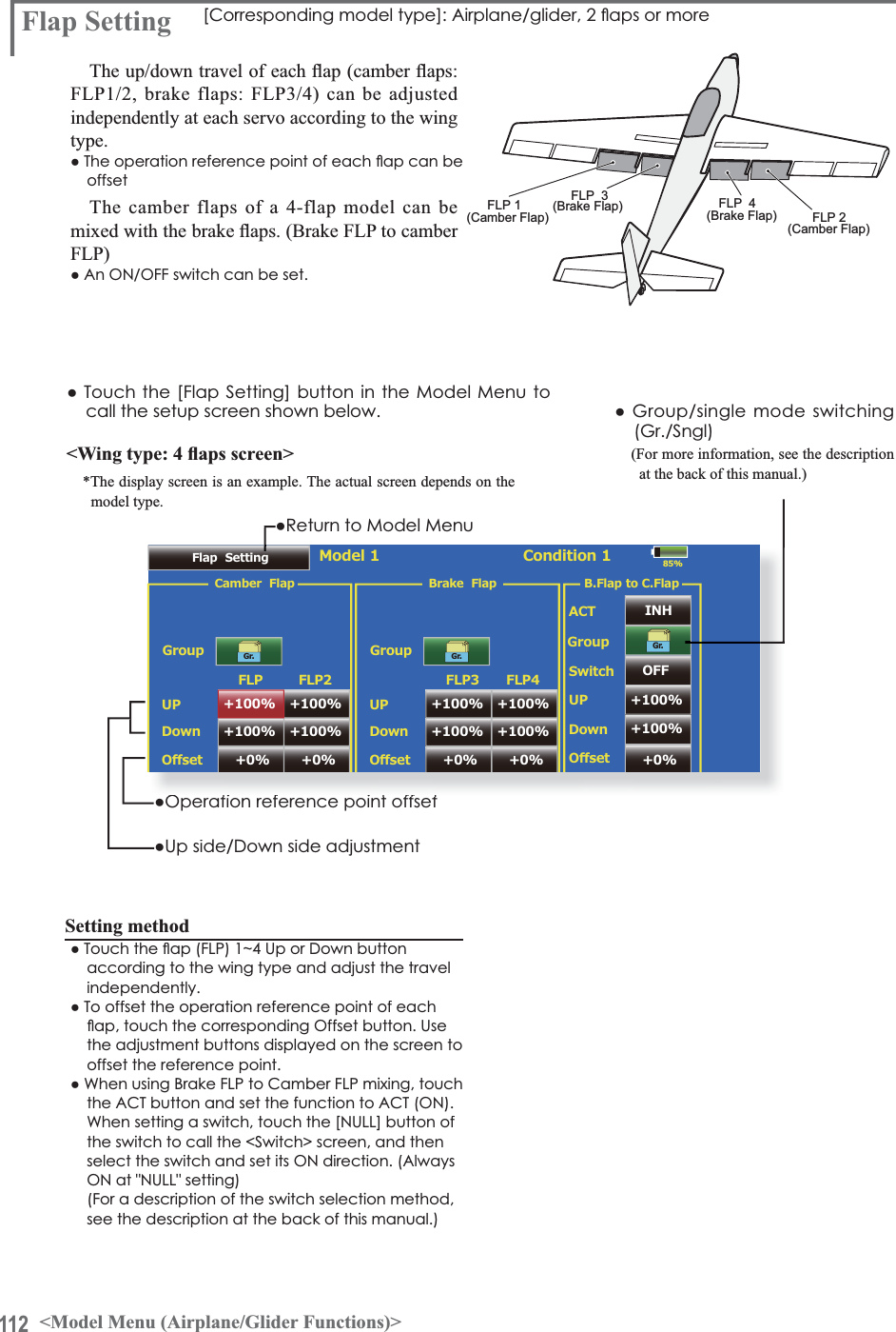
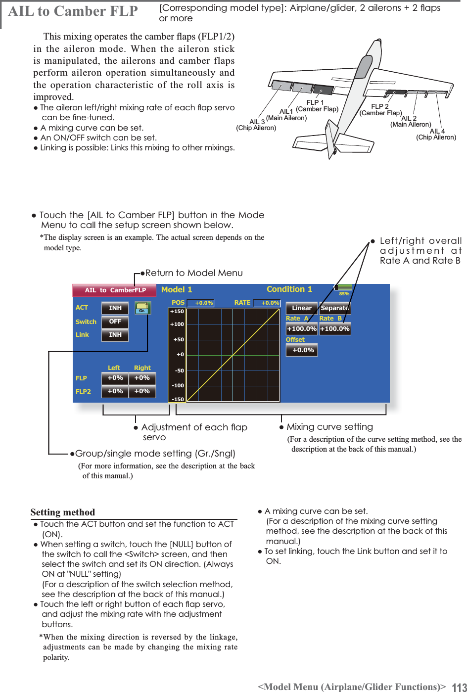
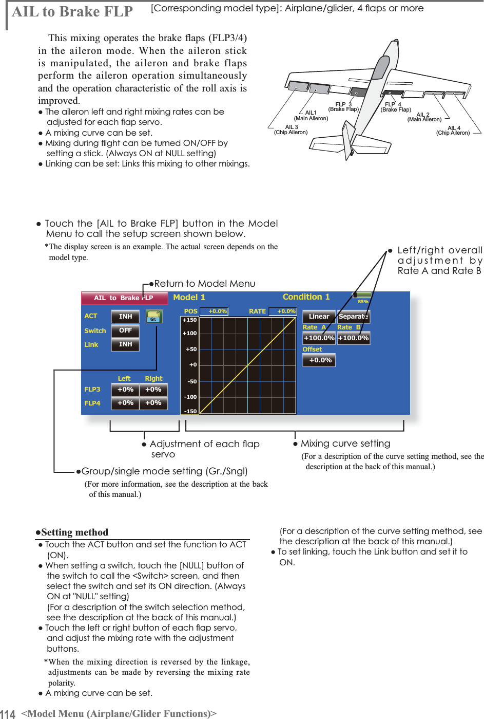
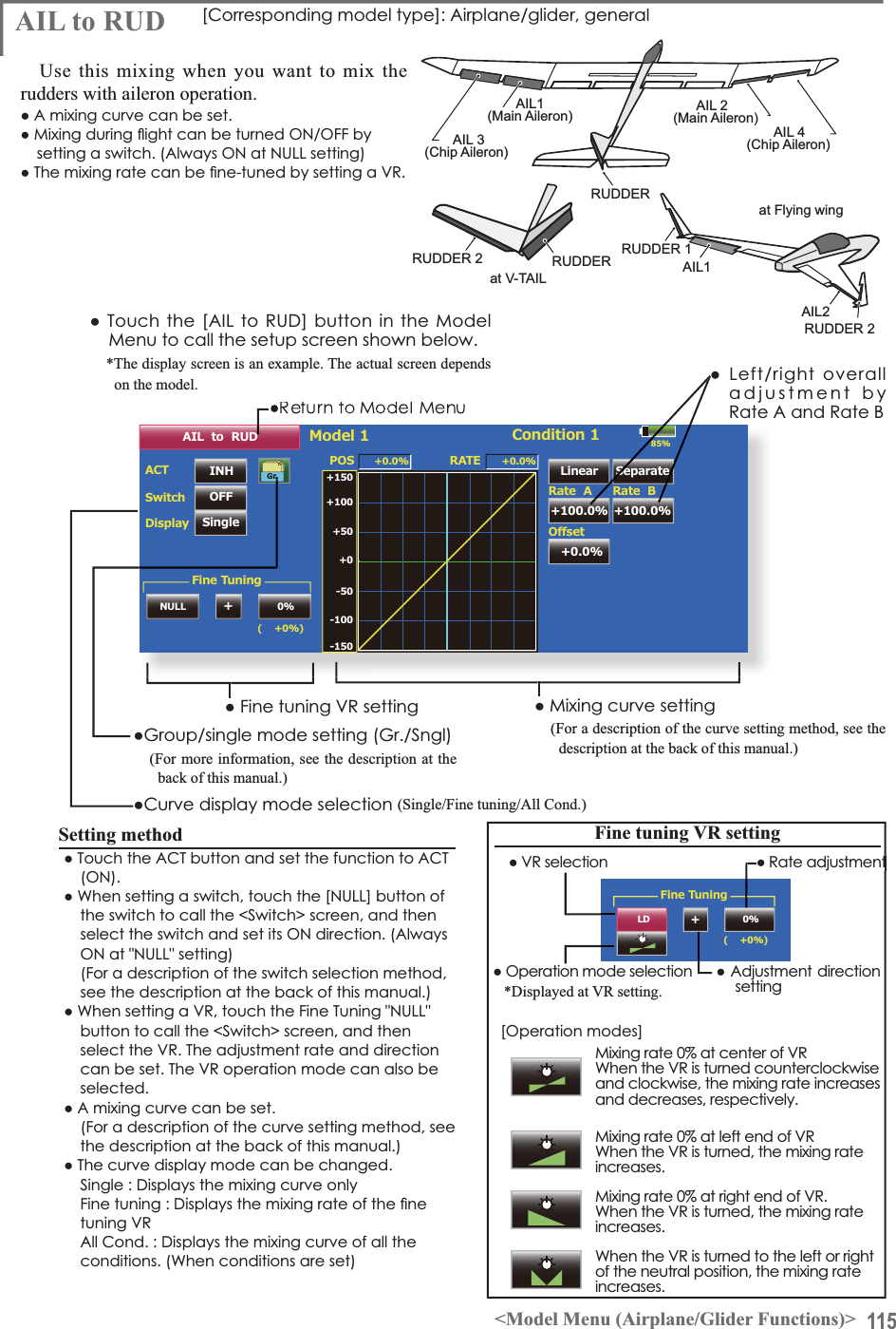
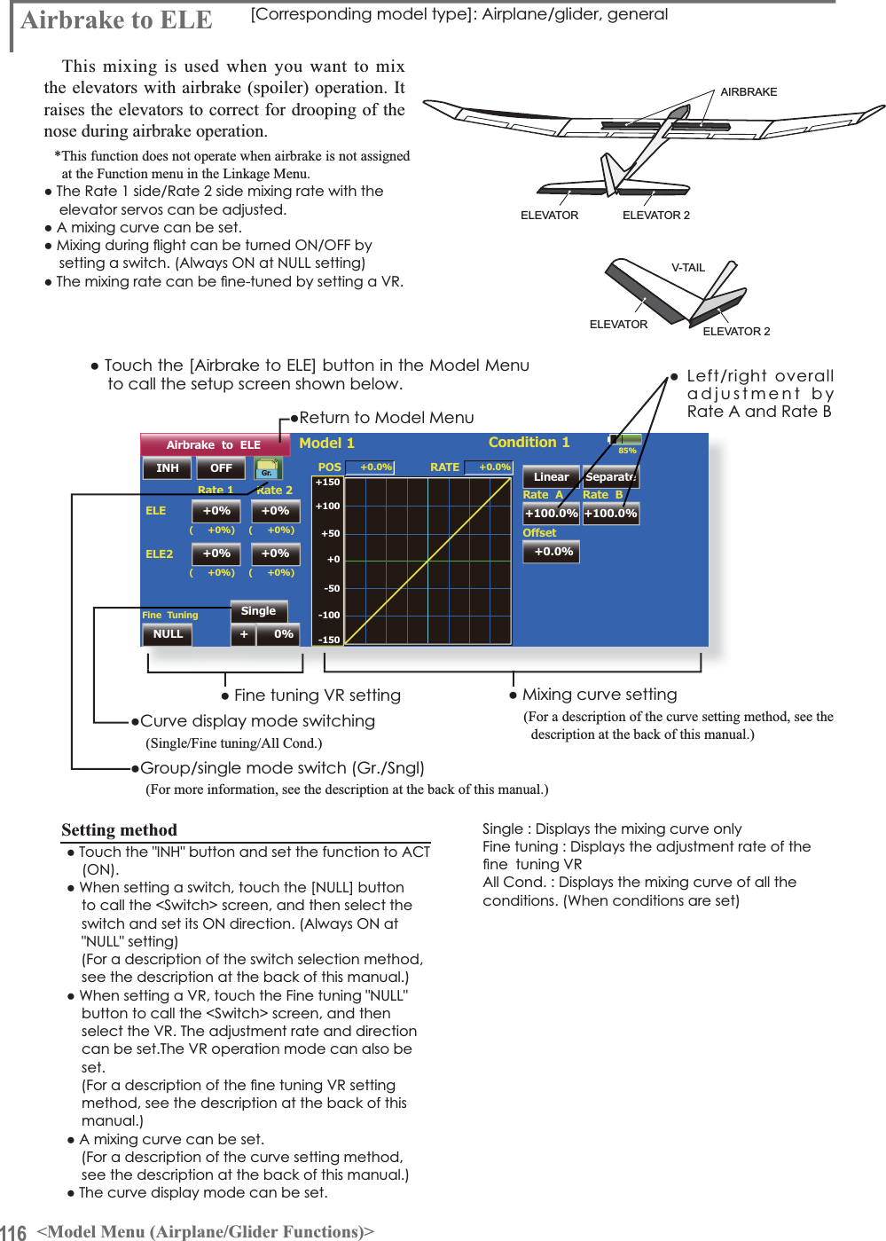
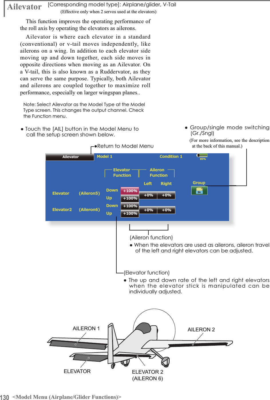
![109<Model Menu (Airplane/Glider Functions)>MODEL MENU (AIRPLANE/GLIDER FUNCTIONS)System Menu Linkage Menu Model Menu ReturnModel 1 Condition 1 85%Model MenuCondition Select AFR ( D/R ) Prog. MixesFlap Setting AIL to CamberFLPAirbrake to ELE ELE to CamberRUD to AIL$,/'LíHUHQWLDOServo MonitorAIL to RUDCamberFLP to ELECamber Mix1/2AIL to Brake FLPRUD to ELE Snap Rollairplane, glider, or EP glider model type is selected are displayed in this Model Menu functions section. First use the Model Type function of the Linkage Menu to preset the model type, wing type, and tail type matched to the fuselage used. Later setting resets the data set by mixing function, etc.These dedicated mixings can be set for eachflight condition, as required. When you want touse the system by switching the settings for each condition by switch or stick position, use the &RQGLWLRQ6HOHFWIXQFWLRQWRDGGÀLJKWFRQGLWLRQV(Up to 8 conditions can be used)Note: The T18MZ is designed so that the airplane and glider (including EP glider) model types can handle fuselages of the same wing type.The functions common to airplanes and gliders, except some dedicated functions, are summarized without regard to the model type.The setting items are different, depending on the number of servos, etc. according to the wing type used. However, reread them. The setup screens in the instruction manual are typical examples.ŏ5HWXUQWR+RPHVFUHHQŏ7RXFKWKH0RGHO0HQXEXWWRQRIWKH+RPHVFUHHQWRcall this Model Menu.ŏ:KHQWKHEXWWRQRIWKHIXQFWLRQ\RXZDQWWRVHWLVtouched, a setup screen appears.(Model Menu screen example)*The Model Menu screen depends on the model type. This screen is for model type Airplane Wing Type 4AIL+4FLP.ŏ7RQH[WSDJHModel Menu functions listƔ$,/'LIIHUHQWLDOThis function adjusts the left and right ailerons. 5ROOD[LVFRUUHFWLRQDQG¿QHWXQLQJZLWKD95DUHalso possible. This is convenient when making VHWWLQJVGXULQJÀLJKW[Airplane/glider, 2 ailerons or more]Ɣ)ODS6HWWLQJ7KHÀDSVFDQEHDGMXVWHGLQGHSHQGHQWO\)RUDÀDSVPRGHOWKHFDPEHUÀDSVFDQEHPL[HGZLWKWKHEUDNHÀDSV>$LUSODQHJOLGHUÀDSVRUPRUH@Ɣ$,/WR&DPEHU)/3This mixing operates the camber flaps inthe aileron mode. It improves the operationcharacteristic of the roll axis. [Airplane/glider, 2 DLOHURQVÀDSVRUPRUH@Ɣ$,/WR%UDNH)/3This mixing operates the brake flaps in the aileron mode. It improves the operation characteristic of the roll axis. [Airplane/glider, 4 ÀDSVRUPRUH@Ɣ$,/WR58'This mixing is used when you want to operate the rudder at aileron operation. Banking at a shallow bank angle is possible. [Airplane/glider, 2 DLOHURQVÀDSVRUPRUH@Ɣ$LUEUDNHWR(/(This mixing is used to correct operation of the airbrakes (spoilers) when landing. [Airplane/glider, general]Ɣ58'WR$,/This mixing is used to correct roll maneuvers,knife edge, etc. of stunt planes. [Airplane/glider, general]](https://usermanual.wiki/Futaba/T18MZ-24G.User-manual-3-Page-101-162/User-Guide-1596944-Page-9.png)
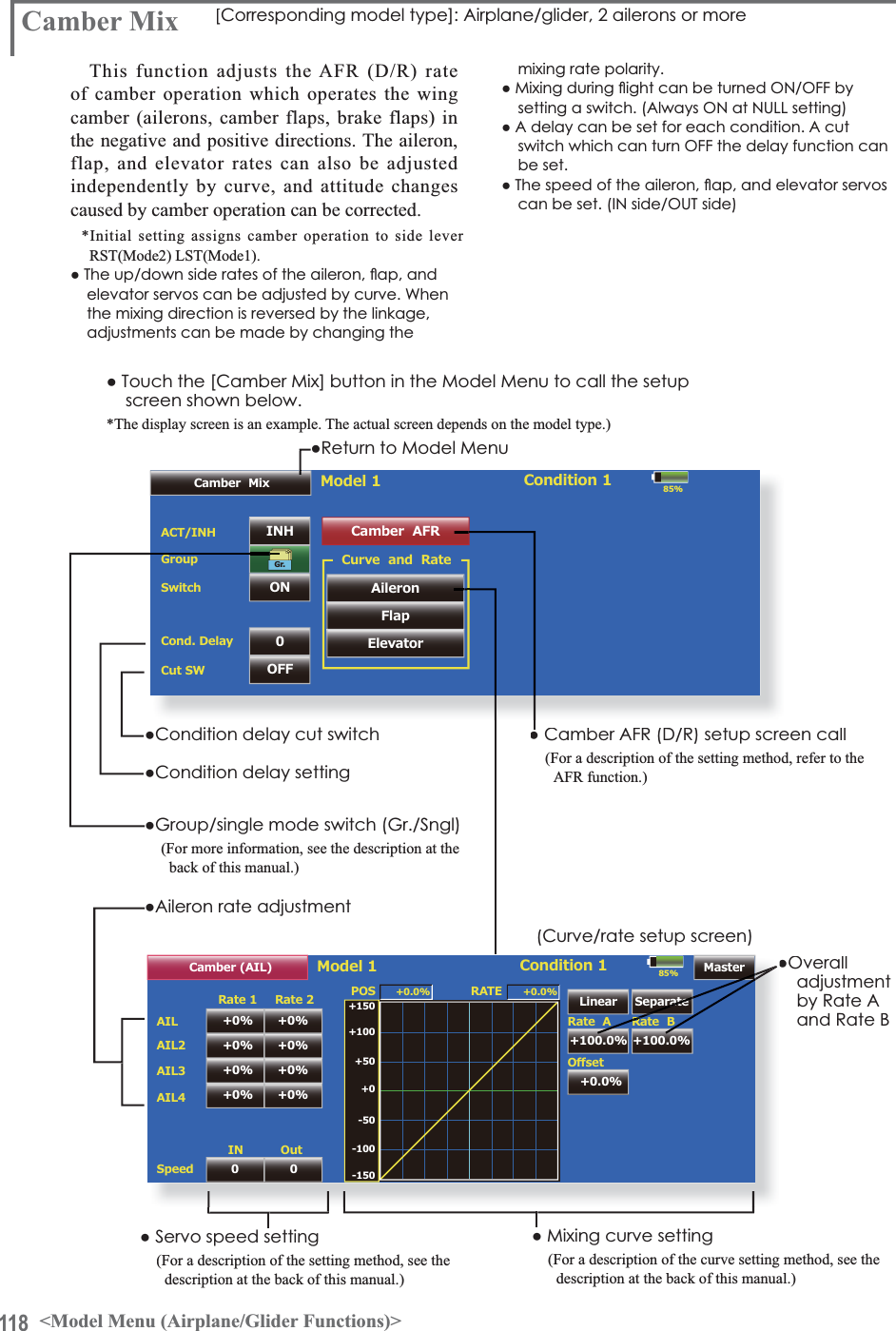
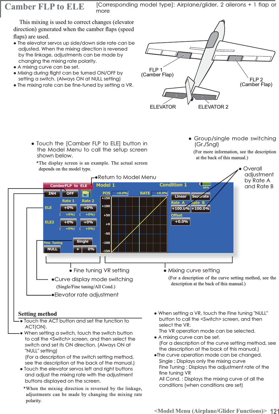
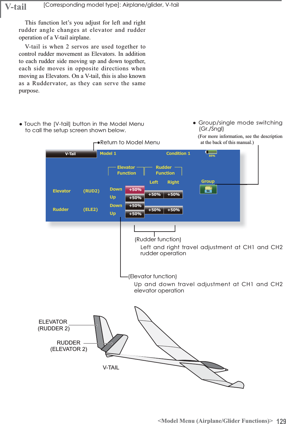
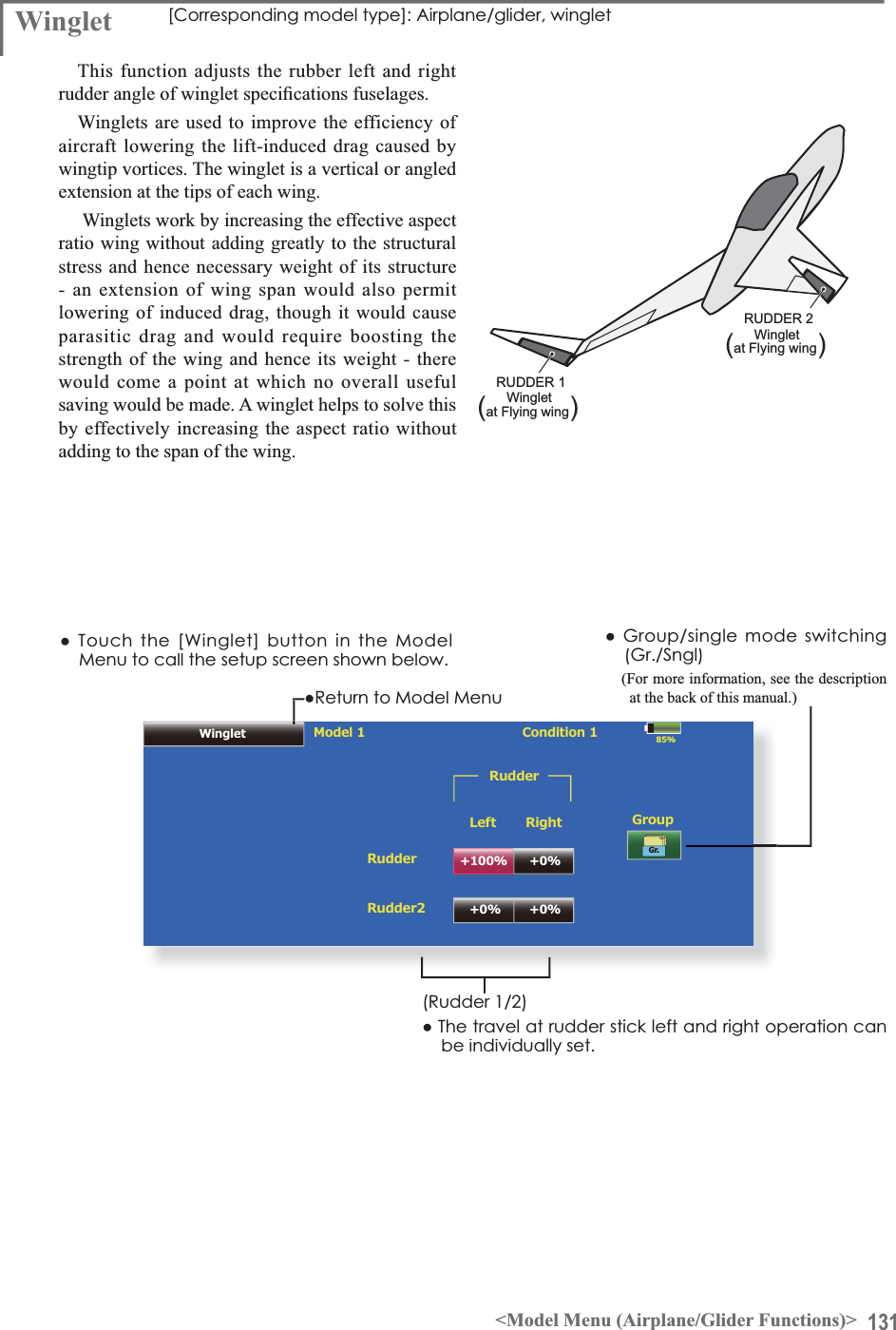
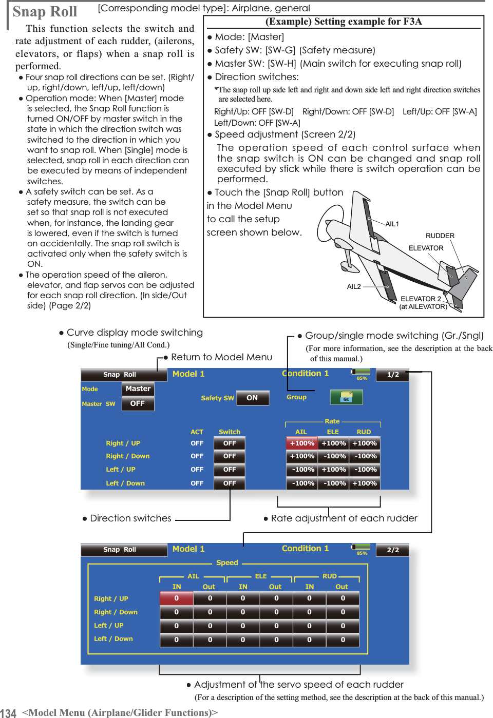
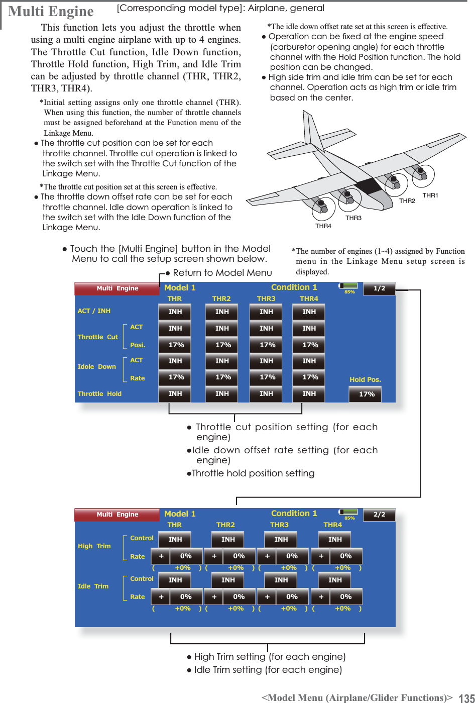
![110 <Model Menu (Airplane/Glider Functions)>AIR BRAKEAIL 3(Chip Aileron)AIL 4(Chip Aileron)AIL1(Main Aileron) AIL 2(Main Aileron)FLP 2(Camber Flap)FLP 1(Camber Flap)V-TAILat AILEVATORFLP 3(Brake Flap)FLP 4(Brake Flap)RUDDER 2 WingletRUDDER 1(ELEVATOR 2)RUDDERRUDDERELEVATOR(RUDDER 2) Wingletat Flying wingat Flying wingat Flying wing( )( )ELEVATOR(AILERON 5)ELEVATOR 2(AILERON 6)Ɣ&DPEHU0L[This mixing adjusts the camber and corrects the elevators. [Airplane/glider, 2 ailerons or more]Ɣ(/(WR&DPEHUThis mixing is used when you want to the mix FDPEHUÁDSVZLWKHOHYDWRURSHUDWLRQ/LIWLQJIRUFHcan be increased at elevators up. [Airplane/glider, 2 ailerons or more]Ɣ&DPEHU)/3WR(/(This mixing is used to correct for attitude changes ZKHQWKHFDPEHUÁDSVDUHEHLQJXVHG>$LUSODQHJOLGHUDLOHURQVÁDSRUPRUH@Ɣ%XWWHUÀ\&URZThis function is used when powerful brake operation is necessary. [Glider, 2 ailerons or more]Ɣ7ULP0L[7KHDLOHURQVHOHYDWRUVDQGÁDSVWULPRIIVHWUDWHFDQbe called by switch or condition selection. [Glider, 2 ailerons or more]Ɣ$LUEUDNHThis function is used when airbrakes are necessary ZKHQODQGLQJRUZKHQGLYLQJHWFGXULQJÁLJKW(Airplane, general)Ɣ*\URThis is dedicated mixing when a GYA Series gyro is used. [Airplane/glider, general]Ɣ9WDLOThis function adjusts the elevators and rudder of 9WDLOPRGHOV>$LUSODQHJOLGHU9WDLOVSHFLÀFDWLRQV@Ɣ$LOHYDWRUThis function adjusts the elevators and ailerons of PRGHOVZLWKHOHYDWRUVSHFLÀFDWLRQV>$LUSODQHJOLGHUHOHYDWRUVSHFLÀFDWLRQV@Ɣ:LQJOHWThis function adjusts the left and right rudders of winglet models. [Airplane/glider, winglet VSHFLÀFDWLRQV@Ɣ0RWRUThe operation speed when the motor of F5B and other EP gliders is started by switch can be set. [EP glider, general]Ɣ58'WR(/(This function is used to correct roll maneuvers, knife edge, etc. of stunt planes. [Airplane, general]Ɣ6QDSUROOThis function selects the snap roll switch and adjusts the steering angle of each rudder. Servo speed can also be adjusted. [Airplane general]Ɣ0XOWL(QJLQHThis function adjusts the throttles independently when using a multi engine model. (Maximum 4 engines) [Airplane, general]](https://usermanual.wiki/Futaba/T18MZ-24G.User-manual-3-Page-101-162/User-Guide-1596944-Page-10.png)
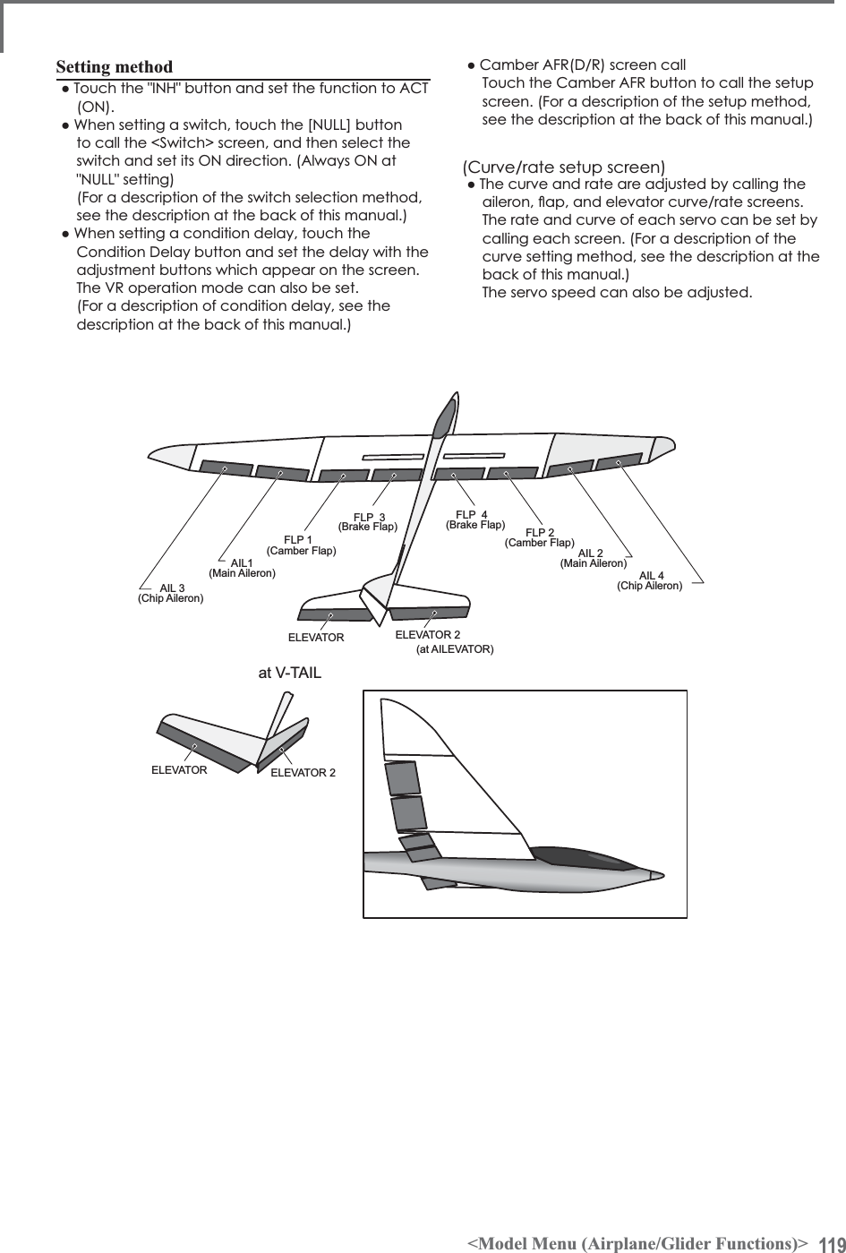
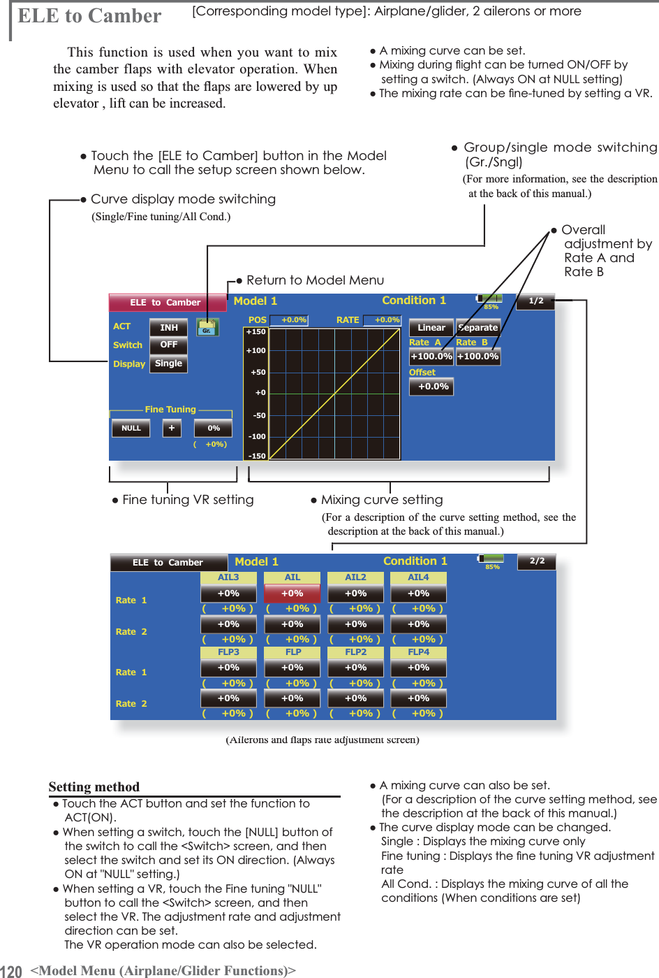
![111<Model Menu (Airplane/Glider Functions)>AIL 3(Chip Aileron) AIL 4(Chip Aileron)AIL1(Main Aileron) AIL 2(Main Aileron)85%$,/'LíHUHQWLDO100%/HIW 5LJKWPOS +0.0%100%100%AIL2 100%100%AIL3 100%100%NULLAIL4)LQH7XQLQJ)LQH7XQLQJ&XUYH100%AIL0DVWHU/LQHDU 6HSDUDWH+100.0% +100.0%0RGHO &RQGLWLRQ*U +100+50+05$7(5DWH$+0.0%2íVHW5DWH%+0.0%ŏ5HWXUQWR0RGHO0HQXŏ7RXFKWKH>$,/'LIIHUHQWLDO@EXWWRQLQWKH0RGHO0HQXWRcall the setup screen shown below.AIL Differential [Airplane/glider, 2 ailerons or moreThe left and right ailerons differential can beadjusted independently. The differential rate canalso be adjusted according to the flying state by VHWWLQJD¿QHWXQLQJ95ŏ$ÀQHWXQLQJFXUYHFDQEHVHWNote: Aileron up/down setting (%) reset is +100% when reset when setting is +, and -100% when reset ZKHQVHWWLQJLV/HIWDQGULJKWPL[LQJFDXVHVDQGWRFKDQJH%HIRUHÁ\LQJFRQÀUPWKHGLUHFWLRQRIoperation.ŏ&DOOVWKH$)5VFUHHQGLUHFWO\when adjusting aileronRSHUDWLRQ$)5ŏ)LQHWXQLQJ95VHWWLQJ7KHJUDSKLVRSHUDWHGE\VHWWLQJD95HWFŏ*URXSVLQJOHPRGHVZLWFKLQJ*U6QJO(For more information, refer to the description at the back of this manual.)ŏ$LOHURQOHIWULJKWadjustment:LQJW\SHDLOHURQVVFUHHQ!*The display screen is an example. The actual screen depends on the Model Type.ŏ2YHUDOOadjustmentE\5DWH$DQG5DWH%*The display is reversed by mixing with aileron operationŏ)LQHWXQLQJFXUYHVHWWLQJ(For a description of the settingmethod, see the description at the end the manual.)6HWWLQJPHWKRGŏ7RXFKWKHDLOHURQ$,/aOHIWRUULJKWEXWWRQand adjust the aileron angles when the stick is moved to the left (or right) end.*The aileron AFR screen can be directly called from the AIL Differential setup screen. ([Master] button)ŏ:KHQVHWWLQJWKHÀQHWXQLQJ95WRXFKWKH18//button to call the <Switch> screen, and then VHOHFWWKHÀQHWXQLQJ95ŏ7KHÀQHWXQLQJUDWHFDQEHVHWE\FXUYHX](https://usermanual.wiki/Futaba/T18MZ-24G.User-manual-3-Page-101-162/User-Guide-1596944-Page-11.png)
![117<Model Menu (Airplane/Glider Functions)>RUDDERAIL1AIL 285%RUD to AILINH OFF POS +0.0%( +0%)Linear Separate+100.0% +100.0%Model 1 Condition 1Gr.+150+100+50+0-50-150-100RATERate A+0.0%2íVHWRate B+0.0%'LVSOD\SingleLinkINHNULL +0%0HPRU\0HPRU\RecallFine Tuningŏ5HWXUQWR0RGHO0HQXRUD to AIL>&RUUHVSRQGLQJPRGHOW\SH@$LUSODQHJOLGHUJHQHUDOThis function is used when you want to mixthe ailerons with rudder operation. It is used when rudder is applied during roll maneuvers, knife edge, etc. of stunt planes. It can be used tobank scale models, large models, etc. like a fullsize plane.ŏ$PL[LQJFXUYHFDQEHVHWŏ0L[LQJGXULQJÁLJKWFDQEHWXUQHG212))E\VHWWLQJDVZLWFK$OZD\V21DW>18//@VHWWLQJŏ7KHUDWHRIFRUUHFWLRQUXGGHUFDQEHPHPRUL]HGby using the memory function. This is convenient ZKHQVHWWLQJDPL[LQJFXUYH:KHQPHPRU\operation (switch operation) is performed in the memory mode with correction rudder applied, the switch operation position at that time is displayed ŏ7RXFKWKH>58'WR$,/@EXWWRQLQWKH0RGHO0HQXWRcall the setup screen shown below.ŏ0L[LQJFXUYHVHWWLQJ(For a description of the curve setting method, see the description at the back of this manual.)ŏ)LQHWXQLQJ95VHWWLQJŏ:KHQVHWWR21E\WRXFKLQJ>,1+@WKHmemory items are displayed.ŏ2YHUDOOadjustment by5DWH$DQG5DWH%RQWKHPL[LQJFXUYH:KHQWKHPHPRU\PRGHLVexited, the memorized points are automatically UHÁHFWHGRQWKHFXUYH:KHQWKHPHPRU\IXQFWLRQLVXVHG/LQHW\SHFXUYHLVDXWRPDWLFDOO\selected.)ŏ/LQNLQJFDQEHVHW/LQNVWKLVPL[LQJWRRWKHUmixings.ŏ7KHPL[LQJUDWHFDQEHÀQHWXQHE\VHWWLQJD956HWWLQJPHWKRGŏ7RXFKWKH,1+EXWWRQDQGVHWWKHIXQFWLRQWR$&721ŏ:KHQVHWWLQJDVZLWFKWRXFKWKH>18//@EXWWRQto call the <Switch> screen, and then select the VZLWFKDQGVHWLWV21GLUHFWLRQ$OZD\V21DW18//VHWWLQJ(For a description of the switch selection method, see the description at the back of this manual.)ŏ:KHQVHWWLQJD95WRXFKWKH)LQHWXQLQJ18//button to call the <Switch> screen and then select WKH957KHDGMXVWPHQWUDWHDQGDGMXVWPHQWdirection can be set,.7KH95RSHUDWLRQPRGHFDQDOVREHVHW)RUDGHVFULSWLRQRIWKHÀQHWXQLQJ95VHWWLQJmethod, see the description at the back of this manual.)ŏ$PL[LQJFXUYHFDQEHVHW(For a description of the curve setting method, see the description at the back of this manual.)ŏ7KHFXUYHGLVSOD\PRGHFDQEHFKDQJHG6LQJOH'LVSOD\VWKHPL[LQJFXUYHRQO\)LQHWXQLQJ'LVSOD\VWKHDGMXVWPHQWUDWHRIWKHÀQHWXQLQJ95$OO&RQG'LVSOD\VWKHPL[LQJFXUYHRIDOOWKHFRQGLWLRQV:KHQFRQGLWLRQVDUHVHWŏ:KHQOLQNLQJ7RXFKWKH/LQNEXWWRQDQGVHWLWWR210HPRU\IXQFWLRQXVDJHPHWKRG([DPSOH8VLQJWKHPHPRU\IXQFWLRQZLWKDQ)$airplane (knife edge correction)*When call switch[SW-A] and memory switch[SW-H] were set[Memory function operation]1. Memory function mode: [Manual][Memory]:KHQWKHPHPRU\VZLWFK6:+ZDVVHWWR21while performing aileron correction when rudder was applied at knife edge, the point position atthat time is memorized. Perform memorization whilechanging the left and right stick positions.7RUHFDOOWKHPHPRUL]HGSRVLWLRQVVHW>6:$@WR217KHPHPRUL]HGFRUUHFWLRQUDWHLVUHÁHFWHGRQWKHcurve, and operation is simultaneously set.1RWH:KHQPHPRUL]HGIURPPDQXDOEHIRUHÀLJKWEHVXUHWKDWthe memory SW is not accidentally set to ON and incorrect mixing setting is not applied when taxiing, starting the engine, etc.Ra](https://usermanual.wiki/Futaba/T18MZ-24G.User-manual-3-Page-101-162/User-Guide-1596944-Page-17.png)
![122 <Model Menu (Airplane/Glider Functions)>85%%XWWHUs\ Model 1 Normal+0% +0% +0% +0%Mixing RateSpeed'LíHUHQWLDO5DWH&RQG'HOD\2íVHW 15%GroupOFFSwitchCut SW OFF000000%+'HOD\ACTAILIn Out AIL3 AIL2 AIL4AIL+0% +0% +0% +0%FLP3 FLP2 FLP4FLPFLPINHGr.%XWWHUs\$)5ELE Setting%XWWHUÀ\ >&RUUHVSRQGLQJPRGHOW\SH@*OLGHUDLOHURQVRUPRUHThis function allows powerful brake operation by simultaneously raising the left and right ailerons and lowering the flaps (camber flap,EUDNHÀDSThis setting will allow the ailerons to be raised while the flaps are simultaneously lowered. %XWWHUÀ\&URZSURGXFHVDQH[WUHPHO\HI¿FLHQWlanding configuration by accomplishing the IROORZLQJ1.Slow the aircraft’s velocity.2. Provide washout at the wing tips to reducethe tendency to tip stall. &UHDWHPRUHOLIWWRZDUGWKHFHQWHURIWKHZLQJDOORZLQJLWWRÁ\DWDVORZHUVSHHGŏ0L[LQJGXULQJÁLJKWFDQEHWXUQHG212))E\VHWWLQJDVZLWFK$OZD\V21DW18//VHWWLQJŏ7KHEXWWHUÁ\RSHUDWLRQUHIHUHQFHSRLQWFDQEHRIIVHW:KHQWKH2IIVHWEXWWRQLVWRXFKHGZKHQoperated to the position to be changed, the UHIHUHQFHSRLQWLVRIIVHW,IWKHUHIHUHQFHSRLQWLVoffset too much, unexpected operation may be performed.ŏ7KHDLOHURQVÁDSVDQGHOHYDWRUVRSHUDWLRQVSHHGFDQEHDGMXVWHG,1VLGH287VLGHŏ$GHOD\FDQEHVHWIRUHDFKFRQGLWLRQ$FXWVZLWFKZKLFKFDQWXUQ2))WKHGHOD\IXQFWLRQFDQalso be set.ŏ7KHGLIIHUHQWLDOUDWHFDQEHDGMXVWHG*When servo binding occurs when setting the ailerons and ÀDSVLQEXWWHUÀ\PL[LQJXVHWKH$)5IXQFWLRQWRDGMXVWWKHrudder angle.ŏ5HWXUQWR0RGHO0HQXŏ:KHQRIIVHWWLQJWKHEXWWHUIO\RSHUDWLRQreference point, operate to the point you ZDQWWRFKDQJHDQGWKHQWRXFKWKH2IIVHWbutton. The reference point displays 0%. :KHQ><HV@LVWRXFKHGWKHUHIHUHQFHSRLQWLVFKDQJHG7KHQLV,QLWLDOL]HGHOHYDWRUFXUYH"is heard, it chooses in which.ŏ'LIIHUHQWLDOUDWHadjustmentŏ7RHOHYDWRUFRUUHFWLRQsetup screenŏ&DOOVWKH%XWWHUÁ\$)5'5VHWXSVFUHHQ(For a description of the setting method, see the description at the back of this manual.)ŏ$LOHURQDQGÁDSVHUYRVVSHHGsetting(For a description of the setting method, see the description at the back of this manual.)ŏ&RQGLWLRQGHOD\VHWWLQJDQGFXWswitch setting(For a description of the setting method, see the description at the back of this manual.)ŏ*URXSVLQJOHPRGHVZLWFKLQJ(Gr./Sngl)(For more information, see the description at the back of this manual.)ŏ7RXFKWKH0L[LQJ5DWH$,/DQG)/3EXWWRQVDQGDGMXVWWKHmixing rates.ŏ7RXFKWKH>%XWWHUÁ\@EXWWRQLQWKH0RGHO0HQXto call the setup screen shown below.(The display screen is an example. The actual screen depends on the model type. The screen shown below is for 4 ailerons DQGÀDSVŏ7RXFKWKH$&7EXWWRQDQGVHWWKHIXQFWLRQWR$&721ŏ:KHQVHWWLQJDVZLWFKWRXFKWKH6:,7&+>18//@EXWWRQWRFDOOWKH6ZLWFK!VFUHHQDQGWKHQVHOHFWWKHVZLWFKDQGVHWLWV21GLUHFWLRQ](https://usermanual.wiki/Futaba/T18MZ-24G.User-manual-3-Page-101-162/User-Guide-1596944-Page-22.png)
![123<Model Menu (Airplane/Glider Functions)>AIL 3(Chip Aileron)AIL 4(Chip Aileron)AIL1(Main Aileron)AIL 2(Main Aileron)FLP 2(Camber Flap)FLP 1(Camber Flap)ELEVATORELEVATOR 2at V-TAILELEVATORELEVATOR 2(at AILEVATOR)FLP 3(Brake Flap)FLP 4(Brake Flap)85%+0%Rate 1 Rate 2IN OutPOS +0.0%ELE2ELEReturnLinear Separate+100.0% +100.0%Model 1 NormalRATERate A+0.0%2íVHWRate B+0.0%+150+100+50+0-50-150-100%XWWHUs\+0%+0%+0%Speed 00ELE Setting([ELE Setup] screen)ŏ7RXFKWKH(/(FRUUHFWLRQUDWHEXWWRQVDQGadjust the rates with the adjustment buttons displayed on the screen.ŏ0L[LQJFXUYHVHWWLQJ(For a description of the curve setting method, see the description at the back of this manual.)ŏ6HUYRVSHHGVHWWLQJ(For a description of the setting method, see thedescription at the back of this manual.)](https://usermanual.wiki/Futaba/T18MZ-24G.User-manual-3-Page-101-162/User-Guide-1596944-Page-23.png)
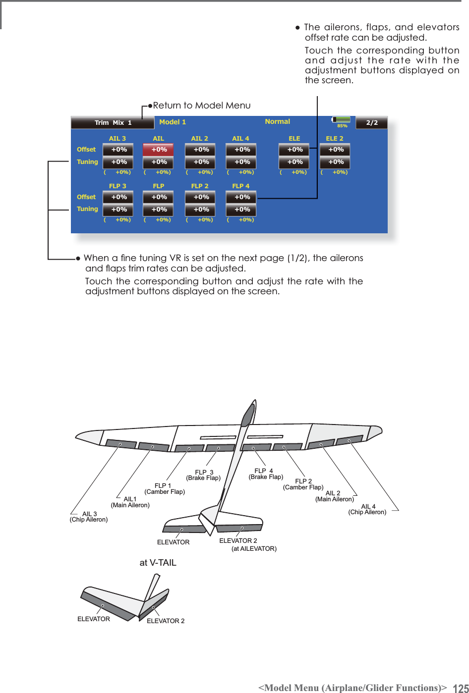
![124 <Model Menu (Airplane/Glider Functions)>85%Model 1 NormalSpeedCond. DelayMode ManualGroupONSwitchCut Switch OFF00000DelayFine TuningNULLControlACT/INHAILIn OutFLP00ELEINHGr.1/2Trim Mix 1ŏ5HWXUQWR0RGHO0HQXŏ*URXSVLQJOHPRGHVZLWFKLQJ(Gr./Sngl)(For more information, see thedescription at the back of this manual.)ŏ:KHQXVLQJDILQHWXQLQJ95WRXFKWKLVbutton to call the <Switch> screen.ŏ&RQGLWLRQGHOD\VHWWLQJIRUDdescription of the setting method, see the description at the back of this manual) and cut switch setting.ŏ$LOHURQVIODSVDQHOHYDWRUVVHUYRspeed setting(For a description of the setting method, see thedescription at the back of this manual.)ŏ0DQXDO$XWRPRGHVHOHFWLRQ0DQXDO6ZLWFKHVWKHIXQFWLRQ212))E\VZLWFKAuto: Trim mix function call can be linked to a stick, etc. A stick switch, etc. separate from the function 212))VZLWFKLVVHW(Trim mix setup page 1/2)h7ULP0L[ >&RUUHVSRQGLQJPRGHOW\SH@*OLGHUDLOHURQVRUPRUHThese functions call the ailerons, elevators, and ÀDSVFDPEHUÀDSVEUDNHÀDSVWULPRIIVHWUDWHVSUHVHWDFFRUGLQJWRWKHÀLJKWVWDWHThe amount of ailerons, elevator, and flapsFDPEHUÀDSEUDNHÀDSWULPRIIVHWFDQEHVHWWRa switch.As an example7ULP 0L[ can be set up for ODXQFKLQJZLWKVSHHGÀDSVDQGDLOHURQVGURSSHGand a slight amount of up elevator.7ULPPL[ can be used for high speed flying, with both DLOHURQVDQGVSHHGÀDSVUHÀH[HGVOLJKWO\DQGDELWof down elevator. The trim functions can be activated during ÀLJKWE\VHWWLQJDVZLWFK7RSUHYHQWVXGGHQWULPFKDQJHVZKHQVZLWFKLQJÀLJKWFRQGLWLRQVDGHOD\can be set to provide a smooth transition between the two. Trim Mix 2 will have priority over Trim Mix 1.ŏ7RXFKWKH>7ULP0L[@EXWWRQLQWKH0RGHO0HQXWRFDOOWKHVHWXSVFUHHQVKRZQbelow.(The display screen is an example. The actual screen depends on the model type. The screen shown below is for 4 DLOHURQVDQGÀDSV(Touch the [1/2] button to switch to page 2.)ŏ7RXFKWKH$&7EXWWRQDQGVHWWKHIXQFWLRQWR$&721ŏ:KHQVHWWLQJDVZLWFKWRXFKWKH6ZLWFKEXWWRQWRFDOOWKH6ZLWFK!VFUHHQDQGWKHQVHOHFWWKHVZLWFKDQGVHWLWV21GLUHFWLRQ$OZD\V21DW18//VHWWLQJ(For a description of the switch selection method, see the description at the back of this manual.)([DPSOH7RXFKWKH$&7EXWWRQDQGVHWWKHWULPPL[IXQFWLRQWR>21@*When separating the settings for each condition, touch thegroup mode button and set it to [Sngl].6HOHFWWKH212))VZLWFK6HOHFWWKH>0DQXDO@RU>$XWR@PRGH,QWKH>$XWR@PRGHDOVRVHOHFWDQDXWR6:7KLVswitch can be linked to a stick, etc.<Speed>,Q7KHRSHUDWLRQVSHHGDWVZLWFK21FDQEHVHW2XW7KHUHWXUQVSHHGDWVZLWFK2))FDQEHVHW<Fine Tuning>The offset rate can be varied in the Fine TuningQXPHULFUDQJHVHWDWVFUHHQ>@E\95HWFselection.&RQGLWLRQ'HOD\!:KHQÁLJKWFRQGLWLRQVDUHVHWWKHRSHUDWLRQVSHHGFDQEHVHWIRUHDFKFRQGLWLRQ&RQGLWLRQGHOD\operation can be interrupted and each rudder quickly returned to its original position by selecting acut switch.](https://usermanual.wiki/Futaba/T18MZ-24G.User-manual-3-Page-101-162/User-Guide-1596944-Page-24.png)
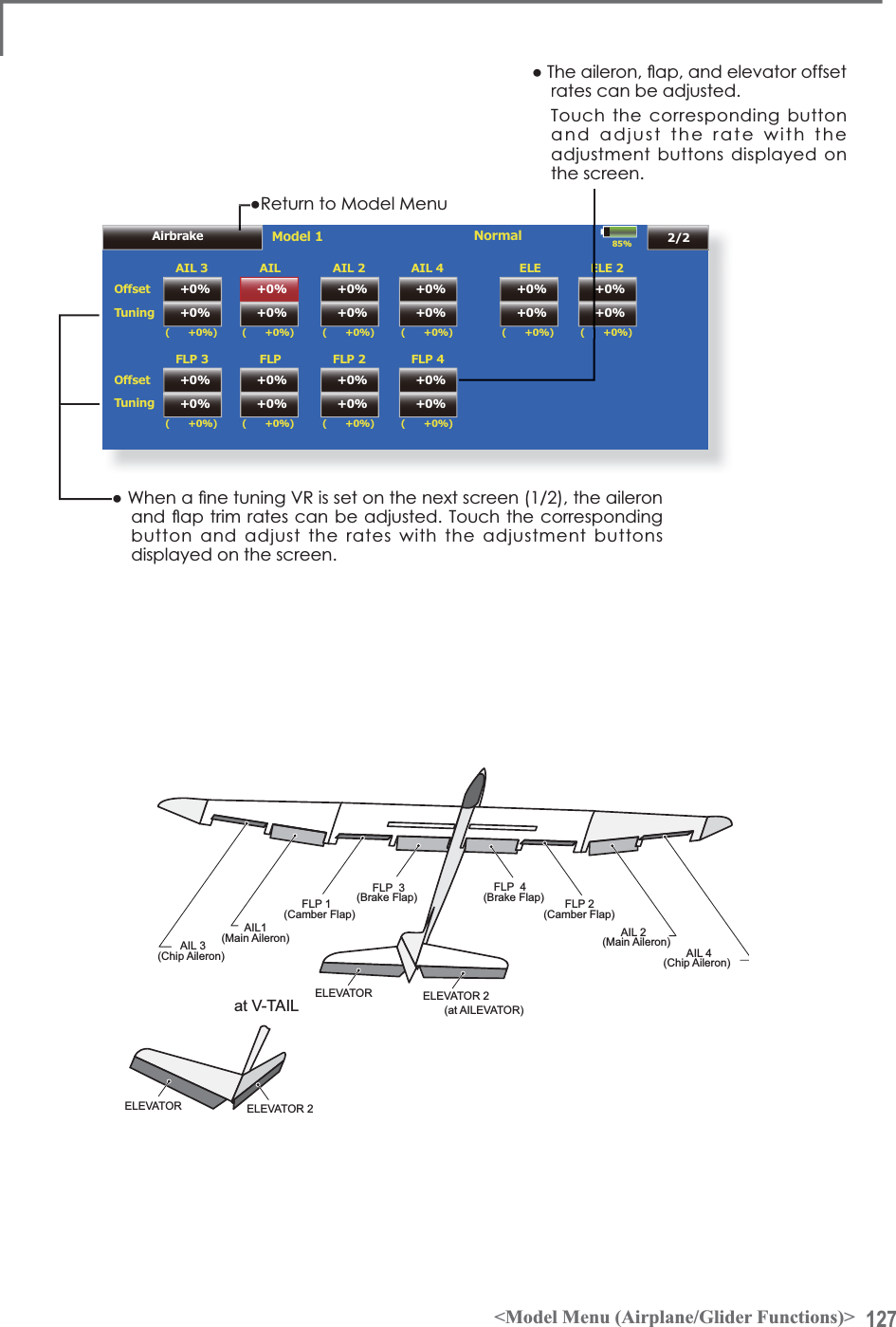
![126 <Model Menu (Airplane/Glider Functions)>85%Model 1 NormalSpeedCond. DelayMode ManualGroupONSwitchCut Switch OFF00000DelayFine TuningNULLControlACT/INHAILIn OutFLP00ELEINHGr.1/2Airbrakeŏ5HWXUQWR0RGHO0HQXŏ*URXSVLQJOHPRGHVZLWFKLQJ(Gr./Sngl)(For more information, see the description at the back of this manual.)ŏ:KHQXVLQJDILQHWXQLQJ95WRXFKWKLVbutton to call the <Switch> screen.ŏ&RQGLWLRQGHOD\VHWWLQJIRUDdescription of the setting method,see the description at the back ofthis manual) and cut switch setting.ŏ$LOHURQVIODSVDQHOHYDWRUVVHUYRspeed setting(For a description of the setting method, see thedescription at the back of this manual.)ŏ0DQXDO$XWRPRGHVHOHFWLRQ0DQXDO6ZLWFKHVWKHIXQFWLRQ212))E\VZLWFKAuto: Trim mix function call can be linked to a stick, etc. A stick switch, etc. separate from the function 212))VZLWFKLVVHW(Airbrake setup screen 1/2)GMh$LUEUDNH >&RUUHVSRQGLQJPRGHOW\SH@$LUSODQHJHQHUDOThis function is used when an air brake is necessary when landing or diving, etc.The preset elevators and flaps (camber flap,brake flap) offset amount can be activated by aswitch.The offset amount of the aileron, elevator, and flap servos can be adjusted as needed. Also the VSHHGRIWKHDLOHURQHOHYDWRUDQGÀDSVHUYRVFDQbe adjusted. (IN side/OUT side) A delay can be set for each condition, and a Cut switch which will turn OFF the delay can be chosen. Trim amounts FDQEHILQHWXQHGE\VHWWLQJD95<RXFDQDOVRset the Auto Mode, which will link Airbrake to a stick, switch, or dial. A separate stick switch or dial can also be set as the ON/OFF switch.ŏ7RXFKWKH>$LUEUDNH@EXWWRQLQWKH0RGHO0HQXWRFDOOWKHVHWXSVFUHHQVKRZQbelow. (The display screen is an example. The actual screen depends on the PRGHOW\SH7KHVFUHHQVKRZQEHORZLVIRUDLOHURQVDQGÁDSVŏ7RXFKWKH$&7EXWWRQDQGVHWWKHIXQFWLRQWR$&721ŏ:KHQVHWWLQJDVZLWFKWRXFKWKH6ZLWFKEXWWRQWRFDOOWKH6ZLWFK!VFUHHQDQGWKHQVHOHFWWKHVZLWFKDQGVHWLWV21GLUHFWLRQ$OZD\V21DW18//VHWWLQJ(For a description of the switch selection method, see the description at the back of this manual.)6HWWLQJH[DPSOHIRU)$DQGRWKHUÀDSHURQVSHFL¿FDWLRQV:KHQDLOHURQVPRGHOW\SHVHOHFWHG(Page 2/2)2IIVHWUDWH$,/>a@$,/>a@(/(>a@1RWH7KHLQSXWQXPHULFVDUHH[DPSOHV$GMXVWWKHWUDYHOWRPDWFKWKHfuselage.(Page 1/2)$&7>21@Group: [Sngl]6ZLWFK>6&&@Mode: [Manual]AIL1FLP 2ELEVATORELEVATOR 2(at AILEVATOR)](https://usermanual.wiki/Futaba/T18MZ-24G.User-manual-3-Page-101-162/User-Guide-1596944-Page-26.png)
![128 <Model Menu (Airplane/Glider Functions)>85%INH GY AVCS AVCSACT TypeOFFSwitchRate1Model 1Gyro0%Gyro Gyro2 Gyro30% AVCS 0%Condition 1Gr.INH GY AVCS AVCSACT TypeOFFSwitchRate2 0%Gyro Gyro2 Gyro30% AVCS 0%Gr.INH GY AVCS AVCSACT TypeOFFSwitchRate3 0%Gyro Gyro2 Gyro30% AVCS 0%Gr.Gyro Rateŏ5HWXUQWR0RGHO0HQX*\UR >&RUUHVSRQGLQJPRGHOW\SH@$LUSODQHJOLGHUJHQHUDO7KLVIXQFWLRQLVXVHGZKHQD*<$6HULHVJ\URis used to stabilize the fuselage attitude. The VHQVLWLYLW\DQGRSHUDWLRQPRGH1RUPDOPRGH*<mode) can be switched with a switch.ŏ7KUHHUDWHV5DWH5DWH5DWHFDQEHswitched.ŏ8SWRD[HV*\UR*\UR*\URFDQEHsimultaneously controlled.*Initial setting does not assign a sensitivity channel. Use the ŏ7RXFKWKH>*\UR@EXWWRQLQWKH0RGHO0HQXto call the setup screen shown below.Function menu of the Linkage Menu to assign the sensitivityFKDQQHO*\UR*\UR*\URXVHGWRDYDFDQWFKDQQHObeforehand. Set [ACT] and [Trim] other than Function to [NULL].ŏ7KHRSHUDWLRQPRGH$9&6125DQGVHQVLWLYLW\RIWKHD[HV*\UR*\UR*\URFDQEHVHWŏ*URXSVLQJOHPRGHVZLWFKLQJ(Gr./Sngl)(For more information, see the description at the back of this manual.)ŏ7KUHHUDWHV5DWH5DWH5DWHFDQEHXVHGŏ7RXFKWKH$&7EXWWRQRIWKHUDWHWREHXVHGDQGVHWWKHIXQFWLRQWR$&7>21@RU>2))@ŏ:KHQD)XWDED*<$J\URLVXVHGZKHQ>*<@W\SHLVVHOHFWHGWKHVHQVLWLYLW\VHWYDOXHLVGLUHFWO\UHDGLQERWKWKH$9&6DQG125PRGHVŏ:KHQVHWWLQJDVZLWFKWRXFKWKHVZLWFKEXWWRQWRFDOOWKH6ZLWFK!VFUHHQDQGWKHQVHOHFWWKHVZLWFKDQGVHWLWV21GLUHFWLRQ(For a description of the switch selection method, see the description atthe end of this manual.)([DPSOH6HWWLQJD[HVXVLQJD*<$DQG*<$D[HVJ\URŏ:LQJW\SH$LOHURQVHUYRVPRXQWHGIXVHODJHVHOHFWHGŏ6HW*\UR*<$&+*\UR*<$&+*\UR*<$&+DWWKH)XQFWLRQPHQXRIWKH/LQNDJH0HQXŏ5DWH>2))@>*<@>6:(@>125@>@>125@>@>125@>@>*U@5DWH>,1+@>*<@>18//@>$9&6@>@>$9&6@>@>$9&6@>@>*U@5DWH>2))@>*<@>6((@>$9&6@>@>$9&6@>@>$9&6@>@>*U@*When separating the conditions, set to [Sngl].6HWVRWKDW5DWHLVWXUQHGRQDWWKHEDFNSRVLWLRQRIVZLWFK(DQG5DWHLVWXUQHG21DWWKHfront position.Since switch E is turned OFF at the center, Rate 2 remains [INH].](https://usermanual.wiki/Futaba/T18MZ-24G.User-manual-3-Page-101-162/User-Guide-1596944-Page-28.png)
![132 <Model Menu (Airplane/Glider Functions)>85%Model 1 Condition 1Speed0RWRU2í +0GroupONSwitchINHACT/INH ACT/INH ONOFFOne time mode+0Speed 1 to 2Speed1Speed2INHGr.MotorINH0000In Outŏ5HWXUQWR0RGHO0HQXMotor>&RUUHVSRQGLQJPRGHOW\SH@(3JOLGHU$LUSODQHJHQHUDOThis function lets you set the operation speed when the motor of a F5B or other EP glider is started by switch. The operation speed can be set in 2 ranges of slow speed flight and high speed ÀLJKW6SHHG6SHHG7KLVIXQFWLRQFDQDOVREHoperated as a safety function by setting 2 switches.ŏ7KH,QVLGHDQG2XWVLGHRSHUDWLQJVSHHGVFDQbe adjusted independently in 2 ranges (Speed 1/Speed 2).ŏ7KHERXQGDU\EHWZHHQWKHUDQJHVFDQEHVHW(From Speed 1 to Speed 2)ŏ7KHVHWRSHUDWLRQVSHHGRSHUDWLRQFDQEHactivated at initial operation only. (1 time operation) However, operation can be repeated ŏ7RXFKWKH>0RWRU@EXWWRQLQWKH0RGHO0HQXto call the setup screen shown below.ŏ0RYHWKHFXUVRUE\VHWVZLWFKRU95E\VHWWLQJWKHVZLWFKWR2))EHIRUHRSHUDWLRQLVÀQLVKHG:KHQ\RXZDQWWRUHVHWWLPHRSHUDWLRQVHWWKH$&7EXWWRQWR>,1+@DQGWKHQUHVHWLWWR>21@ŏ7KHPRWRU&+LVFRQWUROOHGE\6:*>0RGH@6:(>0RGH@,QLWLDOVHWWLQJ:KHQFKDQJLQJWKHVZLWFKRUVWLFNZKLFKFRQWUROVWKHPRWRUÀUVWFKDQJH)XQFWLRQRIWKH/LQNDJH0HQX1RWH:KHQXVLQJWKLVIXQFWLRQDOZD\VFKHFNLQLWLDORSHUDWLRQZLWKWKHSURSHOOHUUHPRYHG1RWH7KHZDUQLQJPHVVDJHLVDSSHDUVZKHQWKHPL[LQJLVRQVWDWXVDWWKHSRZHURQIRUVDIHW\ŏ2SHUDWLRQ7RXFKWKHEXWWRQDQGVHWWKHIXQFWLRQWR21ŏ:KHQ\RXZDQWWRVHWWKH2QHWLPHPRGHWRXFKWKHEXWWRQDQGVHWWKHPRGHWR>21@ŏ6SHHGWRThe Speed 1 and Speed 2 region boundarycan be changed,ŏ2SHUDWLRQVSHHGDGMXVWPHQWThe speed when Speed 1 and Speed 2 are21,QDQG2))2XWFDQEHDGMXVWHGŏ2SHUDWLRQTouch the button and set the function to21ŏ*URXSVLQJOHPRGHVZLWFKLQJ*U6QJO(For more information, see the descriptionat the back of this manual.)ŏ6ZLWFKA switch that turns the function itself212))FDQEHVHOHFWHGŏ0RWRURII[Yes] and [No] are displayed by touchingWKH0RWRU2IIEXWWRQZKHQ>6:*0RGH@>6:(0RGH@LVLQWKHPRWRU2))SRVLWLRQ:KHQ><HV@LVWRXFKHGWKHGLUHFWLRQRIthe motor switch is memorized. The screenJUDSKGLVSOD\21GLUHFWLRQDOVRFKDQJHVNotesŏ)LUVWGHFLGHWKHPRWRU2))SRLQWDQGWKHQVHWWKHVSHHG:KHQ\RXZDQWWRUHVHWWKHPRWRU2))SRLQWDOVRUHVHWWKHVSHHGŏ:HUHFRPPHQGWKDW0RWRU2))EHVHWLQFRPELQDWLRQZLWK)6ŏ6HWWKHEDVLFRSHUDWLRQGLUHFWLRQZLWKWKH5HYHUVHIXQFWLRQWRPDWFKWKHamp used.ŏ$OZD\VVHWWKH0RWRU2))SRVLWLRQ](https://usermanual.wiki/Futaba/T18MZ-24G.User-manual-3-Page-101-162/User-Guide-1596944-Page-32.png)
![133<Model Menu (Airplane/Glider Functions)>85%RUD to ELEINH OFF POS +0.0%( +0%)Linear Separate+100.0% +100.0%Model 1 Condition 1Gr.+150+100+50+0-50-150-100RATERate A+0.0%2íVHWRate B+0.0%'LVSOD\SingleLinkINHNULL +0%0HPRU\0HPRU\RecallFine Tuningŏ5HWXUQWR0RGHO0HQXRUD to ELE >&RUUHVSRQGLQJPRGHOW\SH@$LUSODQHJHQHUDOThis function is used when you want to mix elevator operation with rudder operation. It is used to correct undesirable tendencies when rudder is applied in roll maneuvers, knife edge, etc. of stunt planes.ŏ$PL[LQJFXUYHFDQEHVHWŏ0L[LQJGXULQJÁLJKWFDQEHWXUQHG212))E\VHWWLQJDVZLWFK$OZD\V21DW18//VHWWLQJŏ7KHDPRXQWRIFRUUHFWLRQUXGGHUFDQEHmemorized by using the Memory function. This is ŏ7RXFKWKH>58'WR(/(@EXWWRQLQWKH0RGHO0HQXWRcall the setup screen shown below.ŏ0L[LQJFXUYHVHWWLQJ(For a description of the curve setting method, see the description at the back of this manual.)ŏ)LQHWXQLQJ95VHWWLQJŏ:KHQ>,1+@LVWRXFKHGWKHPHPRU\items are displayed.FRQYHQLHQWDWPL[LQJFXUYHVHWWLQJ:KHQPHPRU\operation (switch operation) is performed with correction rudder applied in the Memory Mode, the stick position at that time is displayed on the PL[LQJFXUYH7KHSRLQWLVDXWRPDWLFDOO\UHÁHFWHGLQWKHFXUYH:KHQWKH0HPRU\IXQFWLRQLVXVHG/LQHLVDXWRPDWLFDOO\VHOHFWHGDVWKHFXUYHW\SHŏ/LQNFDQEHVHW/LQNVWKLVPL[LQJWRRWKHUPL[LQJVŏ7KHPL[LQJUDWHFDQEHÀQHWXQHGE\VHWWLQJD95(Fine tuning)ŏ2YHUDOOadjustmentE\5DWH$DQG5DWH%ŏ*URXSVLQJOHPRGHVZLWFKLQJ*U6QJO(For more information, see the description at the back of this manual.)6HWWLQJPHWKRGŏ7RXFKWKH,1+EXWWRQDQGVHWWKHIXQFWLRQWR$&721ŏ:KHQVHWWLQJDVZLWFKWRXFKWKH18//EXWWRQto call the <Switch> screen, and then select the VZLWFKDQGVHWLWV21GLUHFWLRQ$OZD\V21DW18//VHWWLQJ(For a description of the switch setting method, see the description at the back of this manual.)ŏ:KHQVHWWLQJD95WRXFKWKH)LQH7XQLQJ18//button to call the <Switch> screen, and then VHOHFWWKH957KHÀQHWXQLQJUDWHDQGDGMXVWPHQWdirection can be set.7KH95RSHUDWLRQPRGHFDQDOVREHVHW)RUDGHVFULSWLRQRIWKHÀQHWXQLQJ95VHWWLQJmethod, see the description at the back of this manual.)ŏ7KHFXUYHGLVSOD\PRGHFDQEHFKDQJHG6LQJOH'LVSOD\VWKHPL[LQJFXUYHRQO\)LQH7XQLQJ'LVSOD\VWKHÀQHWXQLQJUDWHRIWKHÀQHWXQLQJ95$OO&RQG'LVSOD\VWKHPL[LQJFXUYHRIDOOWKHFRQGLWLRQV:KHQFRQGLWLRQVDUHVHWŏ:KHQVHWWLQJ/LQNWRXFKWKH/LQNEXWWRQDQGVHWLWWR210HPRU\IXQFWLRQXVDJHPHWKRG([DPSOH8VLQJWKHPHPRU\IXQFWLRQZLWKDQ)$airplane (knife edge correction)*When call switch [SW-A] and memory switch[SW-H] were set[Memory function operation]1. Memory function mode: [Manual] [Memory]:KHQWKHPHPRU\VZLWFK6:+LVVHWWR21while performing elevator correction when rudder was applied at knife edge, the point position at that time is memorized. Memorization is performed while changing the left and right stick positions.7RUHFDOOWKHPHPRUL]HGSRVLWLRQVVHW>6:$@WR217KHPHPRUL]HGFRUUHFWLRQUDWHLVUHÁHFWHGRQWKHcurve, and operation is simultaneously set.1RWH:KHQPHPRUL]HGIURPPDQXDOEHIRUHÀLJKWEHVXUHWKDWthe memory SW is not accidentally set to ON and incorrect mixing setting is not applied when taxiing, starting the engine, etc.AB](https://usermanual.wiki/Futaba/T18MZ-24G.User-manual-3-Page-101-162/User-Guide-1596944-Page-33.png)
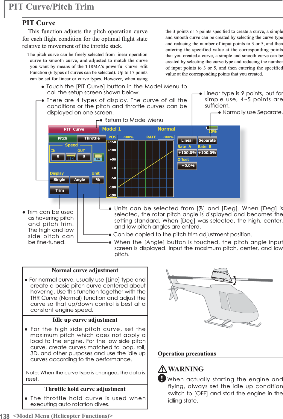
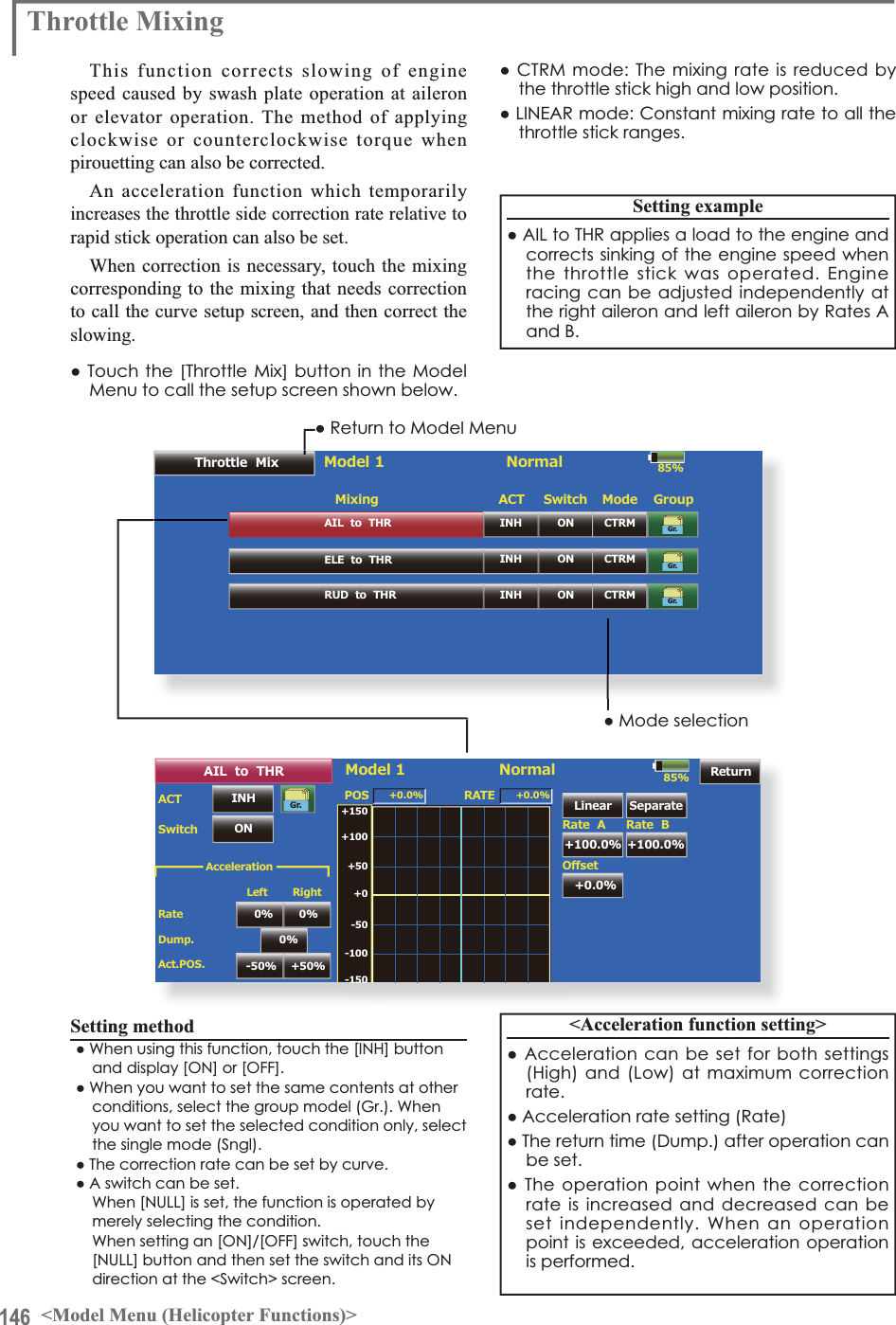
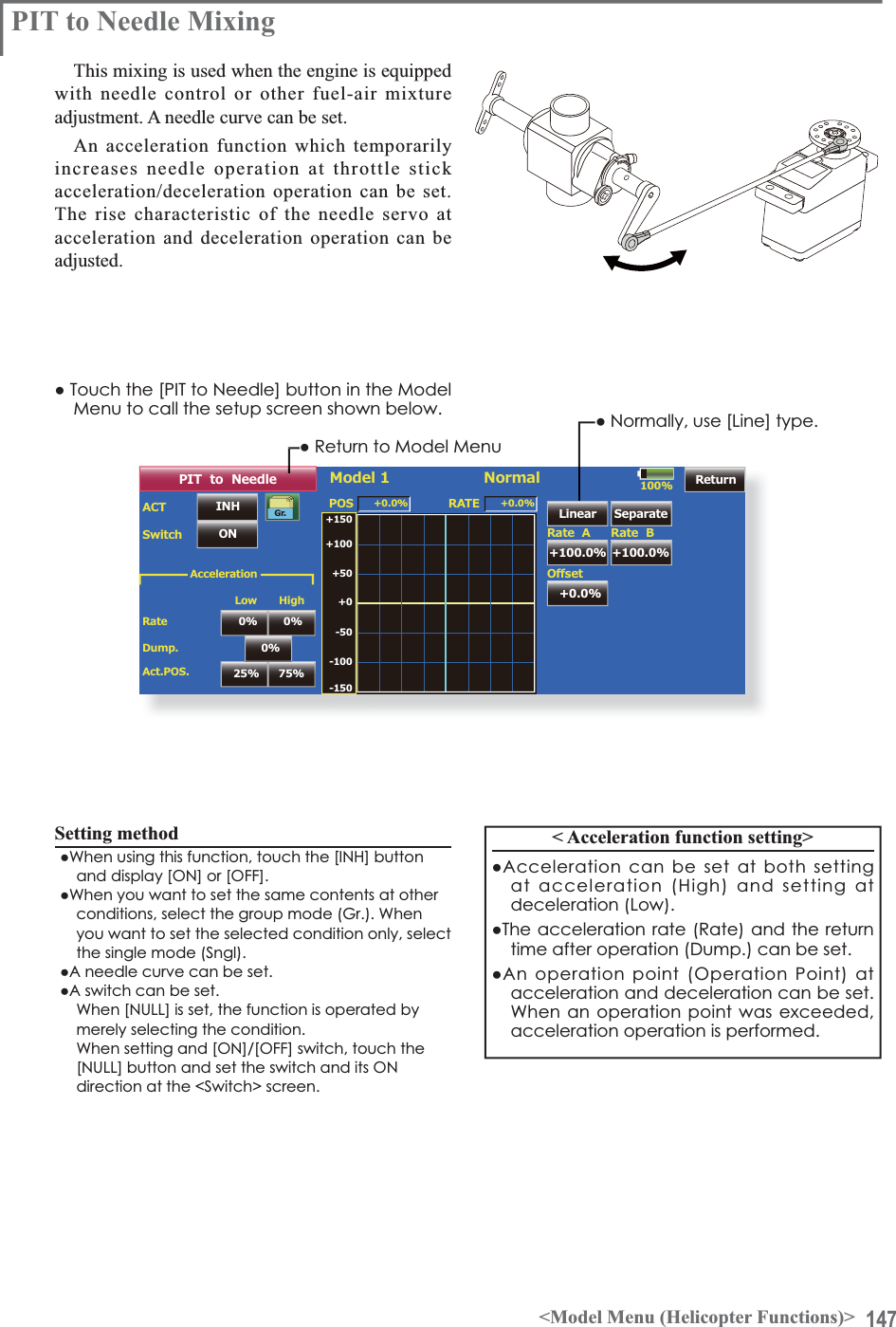
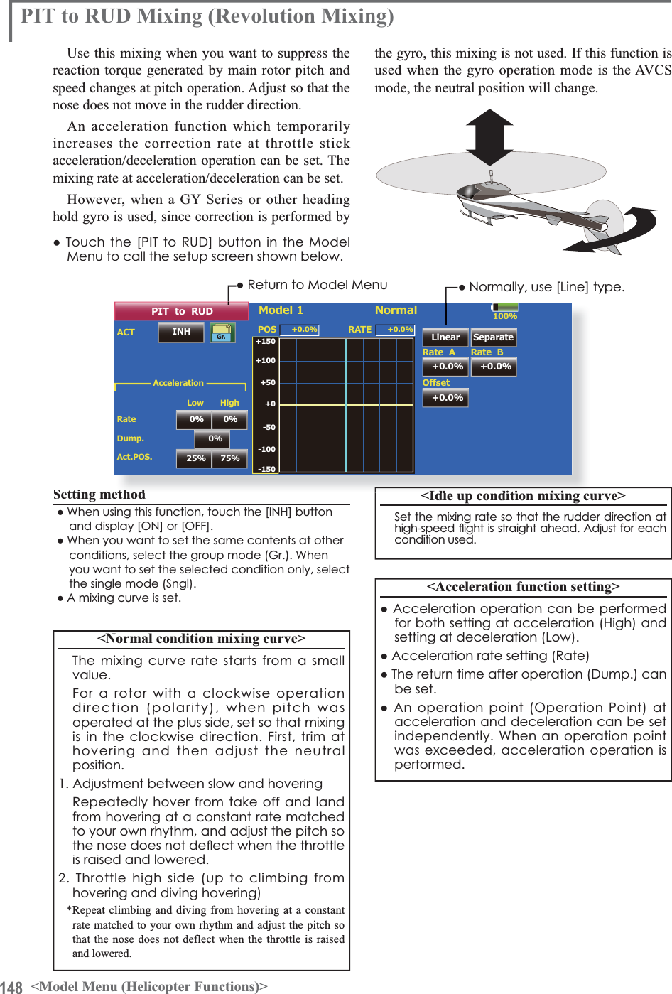
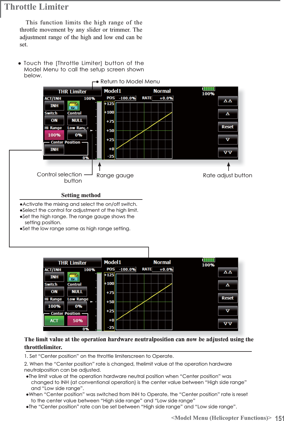
![142 <Model Menu (Helicopter Functions)>Normal Curve Idle-up 1 Curve Idle-up 2 CurveƔ7KURWWOH&XUYH([DPSOH85%Model 1HoverThrottle HoverINHACT/INHModeRateRangeControl( +0%)NormalGr.- 30%100%NULLCTRMThe curves shown below were created by using the Line mode and inputting the data of the 5 points 0% (low side), 25%, 50% (center), 75%, 100% (high) side at each condition. They were created by reducing the number points of the line to 5. When actually creating a curve, enter the data specified per the fuselage (or the reference value).*For a description of the curve creation method, see the description at the back of this manual.Curve setting examplesŏ5HWXUQWR0RGHO0HQXThrottle Hover trimThe Throttle Hover trim setup screen can be called from the THR Curve setup screen.ŏ6HWV7KURWWOH+RYHUWULPŏ6HWVWKHGLDOXVHGThe Throttle Hover function trims the throttlenear the hovering point. Normally, use it with hovering conditions. Changes in rotor speed accompanying changes in the temperature, humidity, and other flight conditions can betrimmed. Adjust the throttle so that rotor rotation is most stable. More delicate trimming is also possible by using this function along with the Hover Pitch function.Setting methodŏ:KHQXVLQJWKHKRYHULQJQRUPDOFRQGLWLRQRQO\VZLWFKWKH>*U@JURXSEXWWRQPRGHWRWKH>6QJO@VLQJOHPRGHDQGPDNHWKHVHWWLQJVŏ6HWWKHIXQFWLRQWR$&7>21@ŏ6HOHFWWKHDGMXVWPHQWNQRE6HOHFWLRQH[DPSOH5'ŏ7KHWULPRSHUDWLRQPRGH0RGH&7501250FDQEHVHOHFWHGCTRM mode: 0D[LPXPUDWHRIFKDQJHQHDUFHQWHUE\FHQWHUWULPRSHUDWLRQNORM mode: 1RUPDOWULPKRUL]RQWDOPRYHPHQWWULPRSHUDWLRQ7KHDGYDQWDJHRIXVLQJWKLVPRGHLVWKDWKRYHULQJWKURWWOHFDQEHDGMXVWHGZLWKRXWFKDQJLQJWKHFXUYHŏ7ULPDGMXVWPHQWUDQJH5DQJHVHWWLQJ:KHQWKHYDOXHLVPDGHVPDOOWULPDFWVRQO\QHDUWKHFHQWHUŏ7KHWULPUDWHFDQEHDGMXVWHGDQGWKHRSHUDWLRQGLUHFWLRQFDQEHVHW](https://usermanual.wiki/Futaba/T18MZ-24G.User-manual-3-Page-101-162/User-Guide-1596944-Page-42.png)
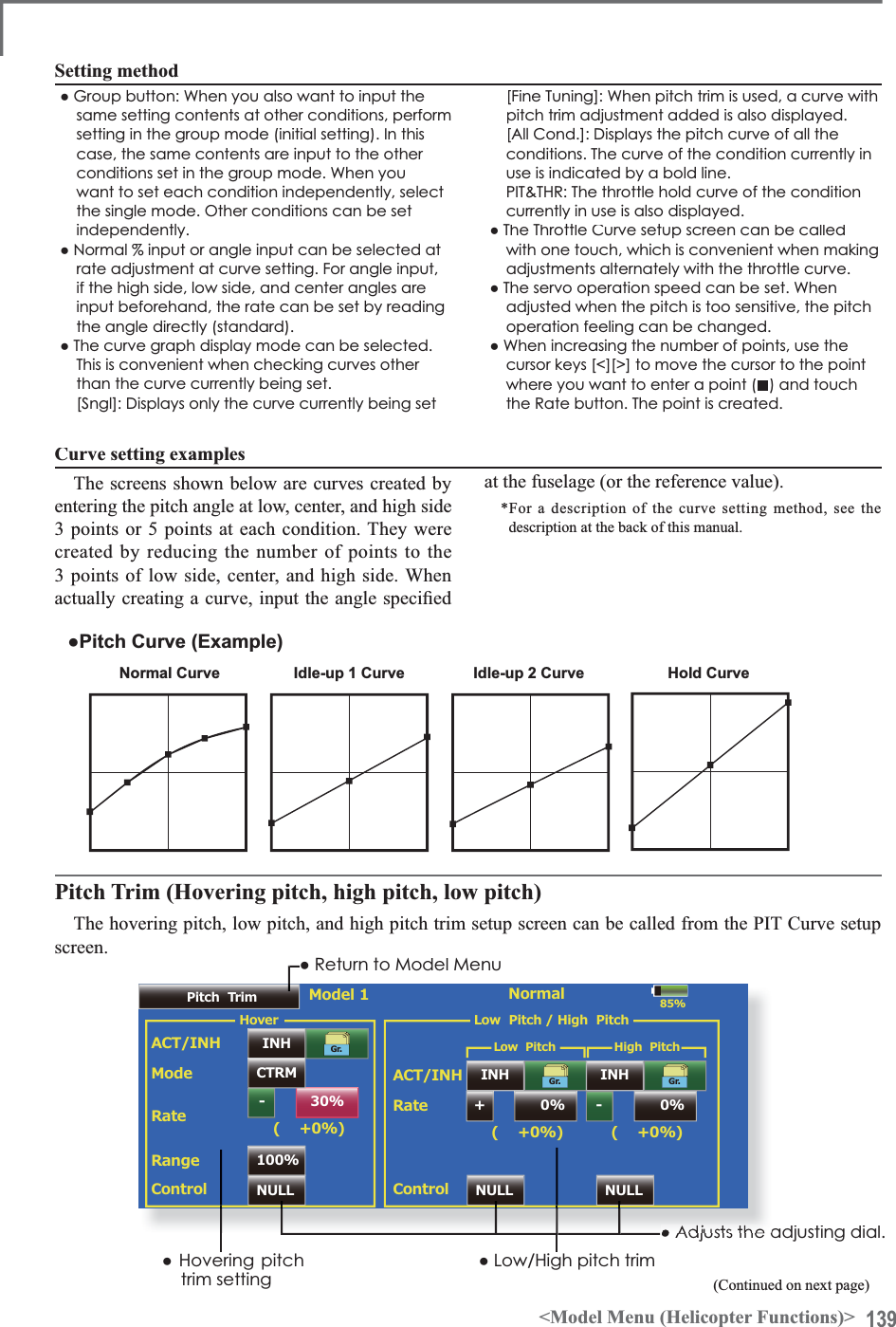
![143<Model Menu (Helicopter Functions)>85%Model 1PitchH100%0%LAccelerationINHACT/INH Gr.25%0%0% 0%75%Active POSDumpingRateLow HighThrottleH100%0%LINHACT/INH Gr.25%0%0% 0%75%Active POSDumpingRateClose OpenAcceleration MixingThis function is used to adjust the pitch and the throttle rise characteristic at acceleration/deceleration operation. An acceleration function which temporarily increases the pitch and throttle operations at throttle stick acceleration/deceleration operation can be set.Example of acceleration function useŏ:KHQXVHGDWSLWFKWKH$FFHOHUDWLRQIXQFWLRQLVHIIHFWLYHZKHQ\RXZDQWWRTXLFNHQWKHUHVSRQVHRIWKHIXVHODJHDW'ÁLJKWÁLSHWF:KHQXVHGKLJKSLWFKWHPSRUDULO\H[FHHGVPD[LPXPSLWFKEXWLPPHGLDWHO\UHWXUQVWRPD[LPXPSLWFK8VLQJ$FFHOHUDWLRQZLWK3LWFKLVHIIHFWLYHZKHQ\RXZDQWWRPD[LPL]HVSHHGIRU'DHUREDWLFVDQGRWKHUDLUFUDIWUHVSRQVHV$VDQH[DPSOH´+LJKSLWFKµWHPSRUDULO\RYHUULGHV´PD[LPXPSLWFKµDQGLPPHGLDWHO\UHWXUQVWRWKHPD[LPXPSLWFKSRVLWLRQŏ5HWXUQWR0RGHO0HQXŏ7RXFKWKH>$FFHOHUDWLRQ@EXWWRQLQWKH0RGHO0HQXWRFDOOWKHVHWXSVFUHHQVKRZQEHORZŏ3LWFKVHWWLQJŏ2SHUDWLRQSRLQWVHWWLQJŏ7KURWWOHVHWWLQJSetting methodŏ$FFHOHUDWLRQFDQEHVHWDWERWKVHWWLQJDWDFFHOHUDWLRQKLJKDQGVHWWLQJDWGHFHOHUDWLRQORZ7KHRSHUDWLRQSRLQWLVGLVSOD\HGRQDJUDSKŏ$FFHOHUDWLRQUDWHVHWWLQJ5DWHŏ7KHUHWXUQWLPHDIWHURSHUDWLRQ'XPSLQJFDQEHVHWŏ7KHRSHUDWLRQSRLQWDWDFFHOHUDWLRQDQGGHFHOHUDWLRQFDQEHVHW:KHQDQRSHUDWLRQSRLQWLVH[FHHGHGDFFHOHUDWLRQLVSHUIRUPHGNote: When using the Acceleration funtion, since the pitch stroke is large, make your settings so there is no binding of your linkage.](https://usermanual.wiki/Futaba/T18MZ-24G.User-manual-3-Page-101-162/User-Guide-1596944-Page-43.png)
![150 <Model Menu (Helicopter Functions)>85%NULLACTOFFSwitchRate1Model 1Governor50.0%Rate CTRL Rate Group Mode+ 0%%20002000rpm1500rpm1000rpmNormal( 50.0%) ( + 0.0%)Rate2Rate3Fine TuningNULLOFF50.0% + 0%( 50.0%) ( + 0.0%)OFF50.0% + 0%( 50.0%) ( + 0.0%)INHINHINH NULLGr.Gr.Gr.Set GOVGovernor MixingThis is used to switch the RPM of the helicopters head. Up to 3 rates can be set for each condition.*The governor is used by connecting the governor speed setting channel to CH7 (initial setting).*When using an independent governor [ON]/[OFF] switch, connect the AUX([ON]/[OFF]) connector of the governor to CH8 (initial setting) and set the switch to Governor2 at the Function menu of the Linkage Menu.ŏ5HWXUQWR0RGHO0HQXŏ7RXFKWKH>*RYHUQRU@EXWWRQRIWKH0RGHO0HQXWRFDOOWKHVHWXSVFUHHQVKRZQEHORZŏ:KHQWKH´0RGHµEXWWRQRQWKH*RYHUQRUVFUHHQLVSUHVVHGWKHGLVSOD\PRGHLVVZLWFKHGUSPPRGHUSPPRGHŏ7KHUSPPRGHDQGUSPPRGHDUHGLIIHUHQWZKHQWKHUDWHLV USPRUJUHDWHU$WUDWHVEHORZWKHUSPGLVSOD\LVWKHVDPHIRUERWKPRGHV:KHQWKHUSPPRGHLVVHW USP7KHPD[LPXPYDOXHLV USP:KHQWKHUSPPRGHLVVHW USP7KHPD[LPXPYDOXHLV USP&RQYHQWLRQDOVSHFLÀFDWLRQVŏ7KHUHLVQRFKDQJHLQWKHWUDQVPLWWHURXWSXWHYHQZKHQWKHUSPPRGHDQGUSPPRGHDUHVZLWFKHG&DOLEUDWLRQPXVWEHSHUIRUPHGDWWKHJRYHUQRUVLGHSetting methodŏ7RXFKWKH>,1+@EXWWRQRIWKHUDWHWREHXVHGDQGGLVSOD\>21@ŏ:KHQ\RXZDQWWRVHWWKHVDPHFRQWHQWVDWRWKHUIXQFWLRQVVHOHFWWKHJURXSPRGH*U:KHQ\RXZDQWWRVHWWKHVHOHFWHGFRQGLWLRQRQO\VHOHFWWKHVLQJOHPRGH6QJOŏ7KUHHVSHHGVUDWHVFDQEHVHWIRUHDFKFRQGLWLRQ5DWH5DWH5DWHŏ(QGSRLQWLQLWLDOL]DWLRQ7KHJRYHUQRURXWSXWFKDQQHOHQGSRLQW$79´WUDYHOµDQG´OLPLWµDUHQRZLQLWLDOL]HGZKHQWKHJRYHUQRUVHWWLQJ´2SHUDWHµEXWWRQZDVSUHVVHGŏ:KHQVZLWFKHGIURP,1+WR21RU2))´WUDYHOµLVLQLWLDOL]HGWRDQG´OLPLWµLVLQLWLDOL]HGWRŏ:KHQ´2SHUDWHµRIUDWHVDQGLVVZLWFKHGWR,1+XQGHUDOOFRQGLWLRQV´WUDYHOµLVLQLWLDOL]HGWRDQG´OLPLWµLVLQLWLDOL]HGWR*When using the Fuel Mixture function, the mixture servo is controlled from the governor. When transmitting the mixture curve data from the transmitter to the governor, the governor AUX (m.trm) connector must be connected to Governor2 function and governor side setting performed. See the governor instruction manual.1RWH$OZD\VVHW$FWDQG7ULPWR>18//@IRU>*RYHUQRU@DQG>*RYHUQRU@RIWKH)XQFWLRQPHQX7KHVXEWULPRI>*RYHUQRU@LVPDGH0DNHWKHUHYHUVHGLUHFWLRQQRUPDO$OVRWKLVPL[LQJDQGWKHJRYHUQRUVLGHVSHHGVHWWLQJPXVWEHPDWFKHGEHIRUHKDQGE\WKHIROORZLQJPHWKRGŏ6HWVRWKDWZKHQWKHJRYHUQRUVLGHLVSODFHGLQWKHVSHHGVHWWLQJLWHPVWDWHDQG>USP@RI6HW*29RIWKHVFUHHQDERYHLVWRXFKHGWKHJRYHUQRUVSHHGLVVHWWRZKHQWKH>USP@EXWWRQLVWRXFKHGWKHJRYHUQRUVSHHGLVVHWWRDQGZKHQWKH>USP@EXWWRQLVWRXFKHGWKHJRYHUQRUVSHHGLVVHWWRŏ:KHQ\RXZDQWWRUHDGWKHVSHHGGLUHFWO\SUHVVWKH>@EXWWRQDQGGLVSOD\>USP@ŏ7KHVSHHGFDQEHZLWFKHGE\VHWWLQJDVZLWFK$OVRZKHQ>2))@LVVHWLQVWHDGRIVSHHGVHWWLQJWKHJRYHUQRUFDQEHWXUQHG>21@>2))@ZLWKRXWVHWWLQJDVHSDUDWH>21@>2))@VZLWFKŏ$VSHHGÀQHWXQLQJ95FDQEHVHW*VR selection, adjustment width, and adjustment directioncan be set.](https://usermanual.wiki/Futaba/T18MZ-24G.User-manual-3-Page-101-162/User-Guide-1596944-Page-50.png)
![153<Data>Servo speed setting (1)IN0 0SpeedOUTThe speed at each operation (including flight condition switching) can be adjusted. Theservos operate smoothly at a constant speed corresponding to the set speed. The operationspeed (In Speed) and the return speed (Out Speed) can be set individually.Switch the operation mode according to the set function. When the button is touched, it toggles between [LIN] and [SYM]."SYM" mode: Mode used with ailerons andother self-neutral functions"LIN" mode:Mode used with functions whichhold the operation position of the throttle and switch channel, etc.>6HWWLQJPHWKRG@6HOHFWWKHIXQFWLRQ>/,1@RU>6<0@PDWFKHGWRWKHPDVWHUchannel. Each time the button is touched, it toggles EHWZHHQ>/,1@DQG>6<0@7RXFKWKH,QRU2XW6SHHGbutton and set the servo speed.Initial value: 06HWWLQJUDQJHaOperations related to servo speedspeed corresponding to the set speed.Master mode: The servo movement istraced by the setting curve. The traceVSHHGLVDGMXVWHGE\LQDQGRXWVSHHG>6HWWLQJPHWKRG@1. When setting the servo speed, touch theSpeed button. The Servo Speed setupscreen shown above is displayed.6HOHFWWKHIXQFWLRQ>/,1@RU>6<0@PDWFKHGto the master channel. Each time theEXWWRQLVWRXFKHGLWWRJJOHVEHWZHHQ>/,1@DQG>6<0@"SYM" mode: Mode used with ailerons andother self-neutral functions."LIN" mode: Mode used with functionswhich hold the operating position of thethrottle and switch channel, etc.3. Touch the In Speed button and set theservo speed.Initial value: 06HWWLQJUDQJHa7RXFKWKH2XW6SHHGEXWWRQDQGVHWWKHservo speed.Initial setting: 06HWWLQJUDQJHa5. Touch the Start Delay button and set theGHOD\WLPHIURPVZLWFK21WRWKHVWDUWRIfunction operation.Initial setting: 0.0 sec6HWWLQJUDQJHaVHFV6. Touch the Stop Delay button and set theGHOD\WLPHIURPVZLWFK2))WRWKHVWDUWRIfunction operation.Initial setting: 06HWWLQJUDQJHaVHFV$WPDVWHUPRGH1. Set desired in and out speed.2. Select the master channel to any toggleswitch.3. The slave channel's servo traces the settingcurve as the master toggle switch is moved.%HORZWKHFDVH$8;VHUYRWUDFHVDQ(;3FXUYHDVWKH6:)LVRSHUDWHGResetServo speed setting (2) (Prog. Mix only)Servo SpeedIn SpeedOut SpeedStart DelayStop Delay0Close0SlaveۢۢSpeed mode: Slave/MasterThe speed mode can be selected. Slave mode: The speed at programmablePL[LQJVZLWFKLQJFDQEHDGMXVWHG7KHservos operate smoothly at a constant](https://usermanual.wiki/Futaba/T18MZ-24G.User-manual-3-Page-101-162/User-Guide-1596944-Page-53.png)
![155<Data>ResetLinear curve adjustmentRate A and Rate B can be adjusted separately or simultaneously.>6HWWLQJPRGHV@ *[Separate] mode:5DWHVDUHDGMXVWHGseparately. *[Combined] mode:5DWHVDUHDGMXVWHGsimultaneously.>6HWWLQJPHWKRG@1. Select the setting mode.7RXFKWKH5DWH$RU5DWH%EXWWRQ8VHWKHDGMXVWPHQWEXWWRQVWRVHWWKHUDWH *Initial value: +100.0%$GMXVWPHQWUDQJHaThe curve can also be offset horizontally in the vertical direction and the rate reference point can be offset to the left or right.>2IIVHWWLQJWKHFXUYHKRUL]RQWDOO\LQWKHYHUWLFDOGLUHFWLRQ@7RXFKWKH2IIVHWEXWWRQ8VHWKHDGMXVWPHQWEXWWRQVWRPRYHWKHFXUYHKRUL]RQWDOO\XSDQGGRZQ *Initial value: +0.0%>2IIVHWWLQJWKHUDWHUHIHUHQFHSRLQWWRWKHOHIWRUULJKW@7RXFKWKH;2IIVHWEXWWRQ8VHWKHDGMXVWPHQWEXWWRQVWRmove the reference point to the left or right. *Initial value: +0.0%Setting by curve typeWhen the curve type is selected as described above, adjustment buttons corresponding to the curve type appear on the original screen. Adjust each curve as described below.(Linear curve)5DWHDGMXVWPHQWEXWWRQVŏ5HWXUQWRLQLWLDOYDOXH](https://usermanual.wiki/Futaba/T18MZ-24G.User-manual-3-Page-101-162/User-Guide-1596944-Page-55.png)
![156 <Data>EXP1 curve adjustmentRate A and Rate B can be adjusted separately or simultaneously. The EXP curves rate (EXP A, EXP B) can also be adjusted separately or simultaneously.>6HWWLQJPRGHV@ *[Separate] mode:5DWHVDUHDGMXVWHGseparately. *[Combined] mode:5DWHVDUHDGMXVWHGsimultaneously.>6HWWLQJPHWKRG@1. Select the setting mode.7RXFKWKHEXWWRQRIWKHUDWHRU(;3FXUYHrate your want to set.8VHWKHDGMXVWPHQWEXWWRQVWRVHWWKHUDWH,QLWLDOYDOXHUDWH(;3UDWHThe curve can also be horizontally offset in the vertical direction.>2IIVHWWLQJWKHFXUYHKRUL]RQWDOO\LQWKHYHUWLFDOGLUHFWLRQ@7RXFKWKH2IIVHWEXWWRQ8VHWKHDGMXVWPHQWEXWWRQVWRPRYHWKHFXUYHKRUL]RQWDOO\XSRUGRZQ *Initial value: +0.0(;3FXUYHŏ8VLQJWKH(;3FXUYHLVKHOSIXOLQsmoothening starting of the ailerons, elevators, rudder, etc.(;3FXUYHŏ8VLQJWKH(;3FXUYHLVKHOSIXOLQHQJLQHrise and other engine control.VTR curve adjustmentRate A and Rate B can be adjusted separately or simultaneously. The VTR curve point positions (P. Pos. A, P. Pos. B) and rates (P. Rate A, P. Rate B) can also be adjusted separately or simultaneously.>6HWWLQJPRGHV@ *[Separate] mode:3RVLWLRQVDQG UDWHVDUHDGMXVWHGVHSDUDWHO\ *[Combined] mode:3RVLWLRQVDQGUDWHVDUHDGMXVWHGVLPXOWDQHRXVO\>6HWWLQJPHWKRG@1. Select the setting mode.2. Touch the button of the rate or VTR curve point position (or rate) you want to set.8VHWKHDGMXVWPHQWEXWWRQVWRVHWWKH975curve point position (or rate).,QLWLDOYDOXHV5DWH33RV$33RV%35DWHThe curve can also be offset horizontally in the vertical direction.>2IIVHWWLQJWKHFXUYHKRUL]RQWDOO\LQWKHYHUWLFDOGLUHFWLRQ@7RXFKWKH2IIVHWEXWWRQ8VHWKHDGMXVWPHQWEXWWRQVWRPRYHWKHFXUYHKRUL]RQWDOO\XSDQGGRZQZLWKWKHDGMXVWPHQWEXWWRQV *Initial value: +0.0%(VTR curve)ŏ6HWWLQJLVIDVWLIOHIWULJKWXSDQGGRZQDUHÀUVWGHFLGHGLQWKH&RPELQHGPRGHand the mode is then switched to the Separate mode.When this curve is used when the operating rudder angle is large such as with acrobatic models, switching from QRUPDOÁLJKWWRDFUREDWLFUXGGHUDQJOHLVperformed without switch operation.](https://usermanual.wiki/Futaba/T18MZ-24G.User-manual-3-Page-101-162/User-Guide-1596944-Page-56.png)
![157<Data>Move DeleteLine and spline curve adjustmentLine curves or spline curves of up to 17 points can be used. (Initial value: 7/9 points) The set points can be freely increased, decreased, and offset. Curves which are symmetrical to the left and right of center can also be set.>6HWWLQJPRGHV@ *[Separate] mode: Normal setting *[Combined] mode: Creates a left and right symmetrical curve.>$GMXVWLQJWKHUDWHRIHDFKSRLQW@8VHWKHPRYHEHWZHHQSRLQWVEXWWRQV>@RU>!!@WRVHOHFWWKHSRLQW7KHSLQNSRLQWLVthe selected point.)2. Touch the Rate button.8VHWKHDGMXVWPHQWEXWWRQVWRDGMXVWWKHrate.[Point addition method]$IWHUWRXFKLQJWKHSRLQWEXWWRQPRYHWKHstick, etc. to the point you want to add and SUHVVWKH>0RYH@EXWWRQ$QRXWOLQHGSRLQWappears on the graph.)2UPRYHWKHVWLFNHWFWRWKHSRVLWLRQ\RXZDQWWRDGGDQGSUHVVWKH>0RYH@EXWWRQ$Qoutlined point appears on the graph.)8VHWKHPRYHEXWWRQV>@RU>!@WRILQHDGMXVWWKHSRVLWLRQ3. Touch the Insert button.$QHZSRLQWLVFUHDWHG[Point deletion]8VHWKHPRYHEHWZHHQSRLQWVEXWWRQ>@RU>!!@DQGVHOHFWWKHSRLQW7KHSLQNSRLQWis the selected point.)7RXFKWKH>'HOHWH@EXWWRQ7KHVHOHFWHGpoint becomes an outlined point.)7RXFKWKHPRYHEHWZHHQSRLQWEXWWRQ>@RU>!!@ *The point is deleted.The curve can also be offset horizontally in the vertical direction.>2IIVHWWLQJWKHFXUYHKRUL]RQWDOO\LQWKHYHUWLFDOGLUHFWLRQ@7RXFKWKH2IIVHWEXWWRQ8VHWKHDGMXVWPHQWEXWWRQVWRPRYHWKHFXUYHKRUL]RQWDOO\XSDQGGRZQ *Initial value: +0.0%(Line curve)(Spline curve)5DWHDGMXVWPHQWEXWWRQV](https://usermanual.wiki/Futaba/T18MZ-24G.User-manual-3-Page-101-162/User-Guide-1596944-Page-57.png)
![162 <Data>Updating70=WUDQVPLWWHUSURJUDPFDQEHXSGDWHG:KHQIXQFWLRQVDUHDGGHGRULPSURYHGWKHXSGDWH¿OHFDQEHGRZQORDGHGIURPRXUZHEVLWH&RS\WKHXSGDWH¿OHVWRWKH6'FDUGDQGWKHQXVHWKHIROORZLQJSURFHGXUHto update the program.Updating procedureNote: If the battery fully discharges during program updating, updating will fail. When the remaining battery capacity is 50% or less, always recharge the battery before updating.Note: The model data in the transmitter can be used unchanged after updating, but to be safe, back up the model data before updating.,QVHUWWKH6'FDUGFRQWDLQLQJWKHXSGDWHÀOHinto the card slot.8VHWZHH]HUVWRVZLWFKWKHVOLGHVZLWFK(update switch) at the side of the card slot inthe up direction.7XUQRQWKHWUDQVPLWWHUSRZHU$QXSGDWHscreen is displayed. Rotary key or the arbitrary direct keys are pressed.4. When updating is complete, the screen shown below appears.7XUQRIIWKHSRZHUVZLWFK$IWHUWKHPRQLWRULED goes off, switch the update switch in thedown direction. If fault happens, an error message can comeout and cannot update.$IWHUWKHXSGDWLQJDERYHKDVEHHQcompleted, turn on the power and then check the system program version at the system menu information screen.FUTABA CORPORATION1080 Yabutsuka, Chosei-mura, Chosei-gun, Chiba-ken, 299-4395, JapanPhone: +81 475 32 6982, Facsimile: +81 475 32 69832011, 12 (1)](https://usermanual.wiki/Futaba/T18MZ-24G.User-manual-3-Page-101-162/User-Guide-1596944-Page-62.png)