Futaba T4PX-24G Radio Control User Manual
Futaba Corporation Radio Control
UserManual.wiki
>
Futaba
>
T4PX-24G User Manual
>
User Manual-Part 1 (Page 1-51)
Contents
1.
User Manual-Part 1 (Page 1-51)
2.
User Manual-Part 2 (Page 52-111)
3.
User Manual-Part 3 (Page 112-163)
User Manual-Part 1 (Page 1-51)
Navigation menu
Upload a User Manual
Namespaces
Wiki Guide
HTML
PDF
Info
Views
User Manual
Discussion / Help
Navigation
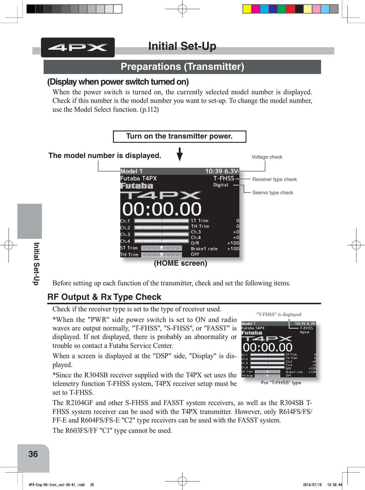
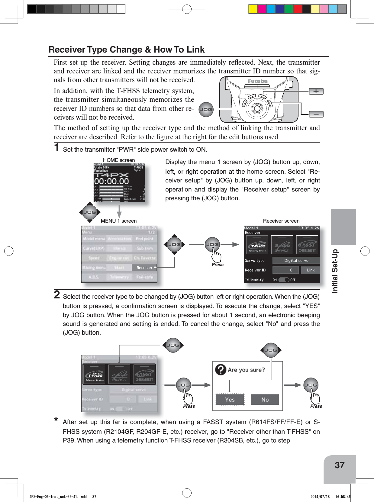
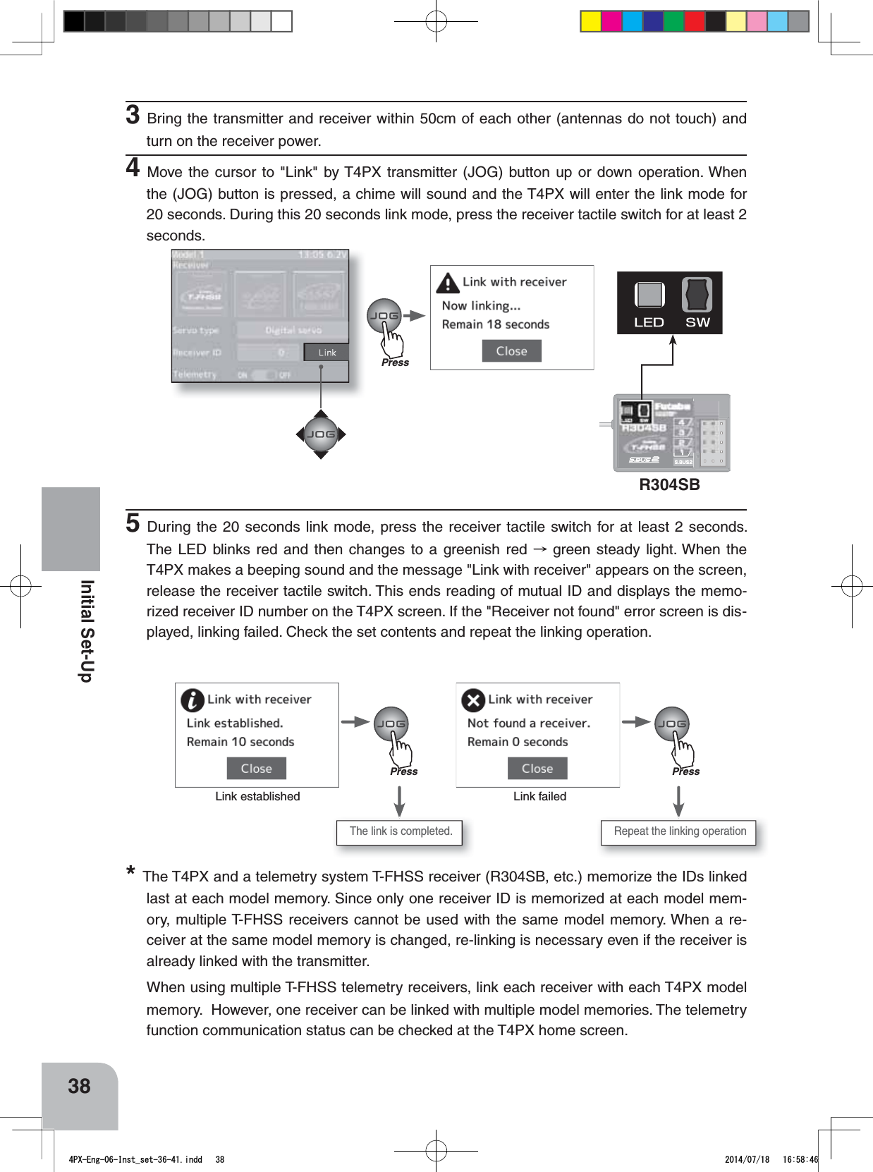
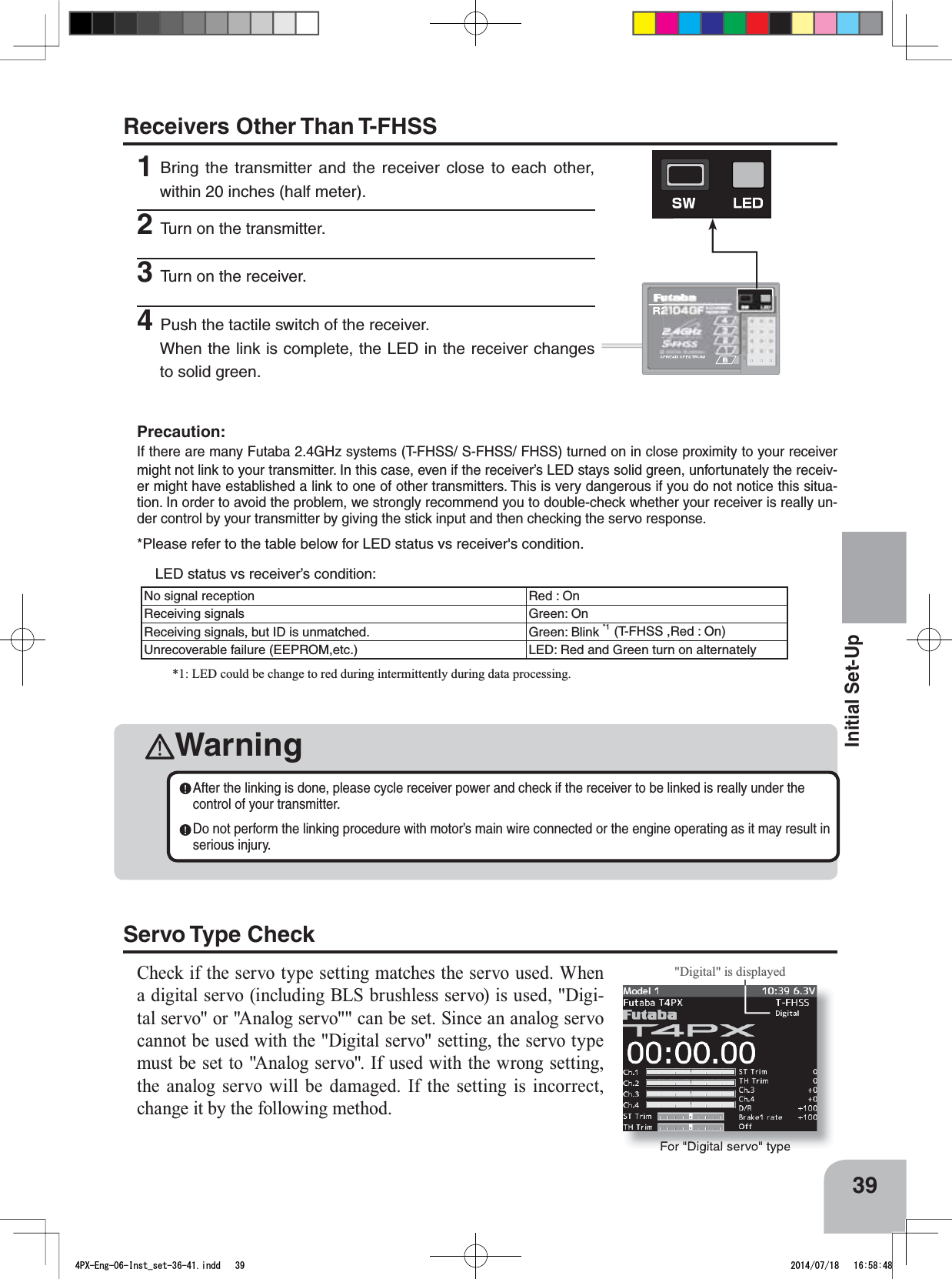
![3• No part of this manual may be reproduced in any form without prior permission.• The contents of this manual are subject to change without prior notice.7KLVPDQXDOKDVEHHQFDUHIXOO\ZULWWHQ3OHDVHZULWHWR)XWDEDLI\RXIHHOWKDWDQ\FRUUHFWLRQVRUFODUL¿FDWLRQVVKRXOGbe made.• Futaba is not responsible for the use of this product.Battery Recycling (for U.S.A.)The RBRC. SEAL on the nickel-cadmium battery contained in Futaba products indicates that Futaba Corporation is voluntarily participating in an industry-wide program to collect and recycle these batteries at the end of their useful lives, when taken out of service within the United States. The RBRC. program provides a convenient alternative to placing used nickel-cadmium batteries into the trash or municipal waste system, which is illegal in some areas. (for USA) You may contact your local recycling center for information on where to return the spent battery. Please call 1-800-8BATTERY for information on NiCd battery recycling in your area. Futaba Corporation involvement in this program is part of its commitment to protect-ing our environment and conserving natural resources. RBRC™ is a trademark of the Rechargeable Battery Recycling Corporation.$SSOLFDWLRQ([SRUWDQG0RGL¿FDWLRQ1. This product may be used for models only. It is not intended for use in any application other than the control of models for hobby and recreational purposes.2. Exportation precautions:(a) When this product is exported from the country of manufacture, its use is to be approved by the laws governing the country of destination for devices that emit radio frequencies. If this product is then re-exported to other countries, it may be subject to restrictions on such export. Prior approval of the appropriate government authorities may be required. If you have purchased this product from an exporter outside your country, and not the authorized Futaba distributor in your country, please contact the seller immediately to determine if such export regulations have been met.(b) Use of this product with other than models may be restricted by Export and Trade Con-trol Regulations, and an application for export approval must be submitted.3. Modification, adjustment, and replacement of parts: Futaba is not responsible for un-DXWKRUL]HG PRGL¿FDWLRQ DGMXVWPHQW DQG UHSODFHPHQW RI SDUWV RQWKLVSURGXFW$Q\VXFKchanges may void the warranty.4PX-Eng-01-P2-3.indd 3 2014/07/18 12:56:04](https://usermanual.wiki/Futaba/T4PX-24G.User-Manual-Part-1-Page-1-51/User-Guide-2346279-Page-2.png)