Futaba T4PX-24G Radio Control User Manual
Futaba Corporation Radio Control
UserManual.wiki
>
Futaba
>
T4PX-24G User Manual
>
User Manual-Part 3 (Page 112-163)
Contents
1.
User Manual-Part 1 (Page 1-51)
2.
User Manual-Part 2 (Page 52-111)
3.
User Manual-Part 3 (Page 112-163)
User Manual-Part 3 (Page 112-163)
Navigation menu
Upload a User Manual
Namespaces
Wiki Guide
HTML
PDF
Info
Views
User Manual
Discussion / Help
Navigation
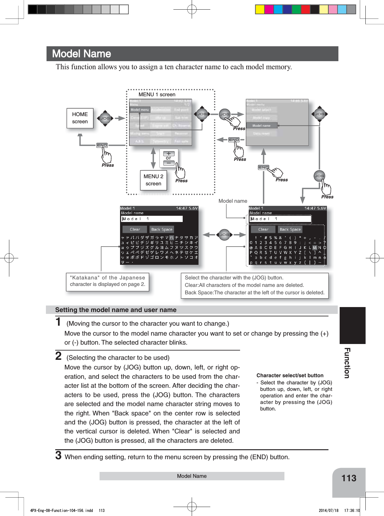
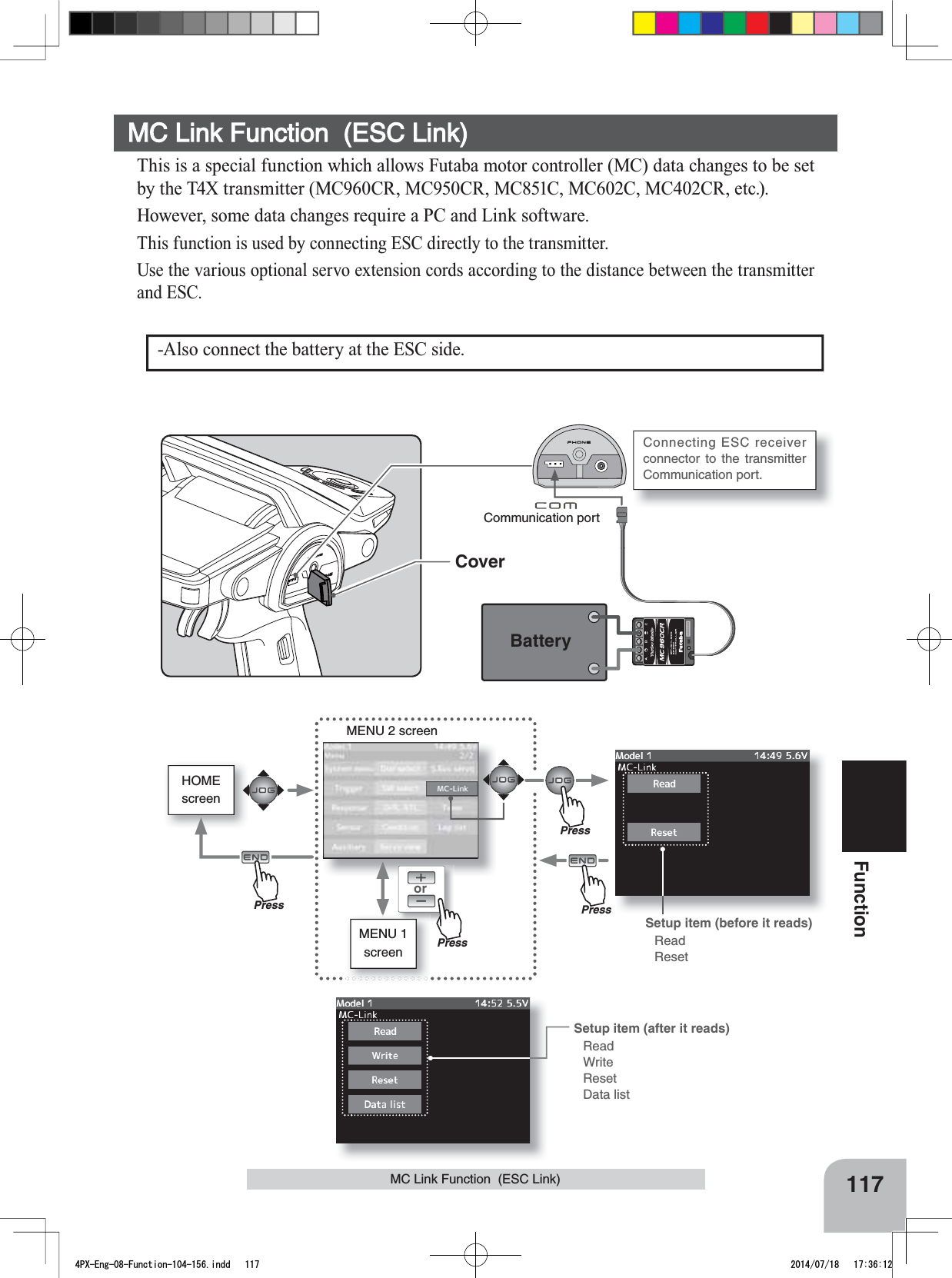
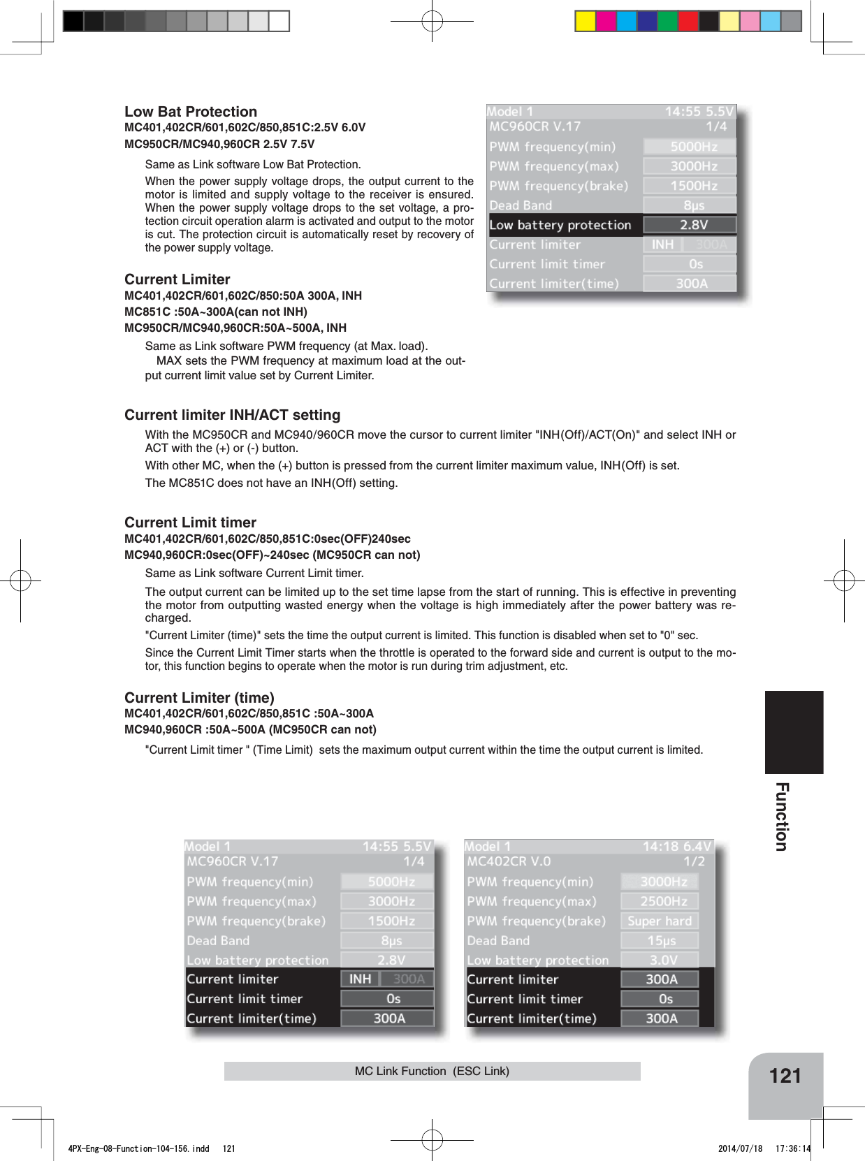
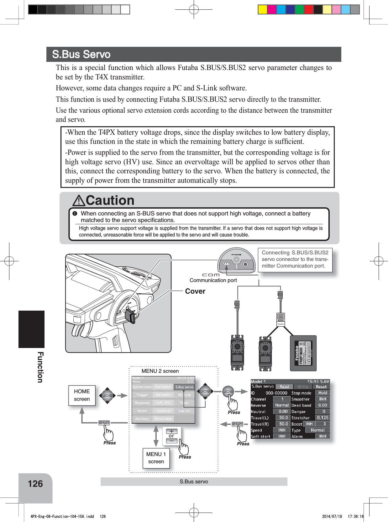
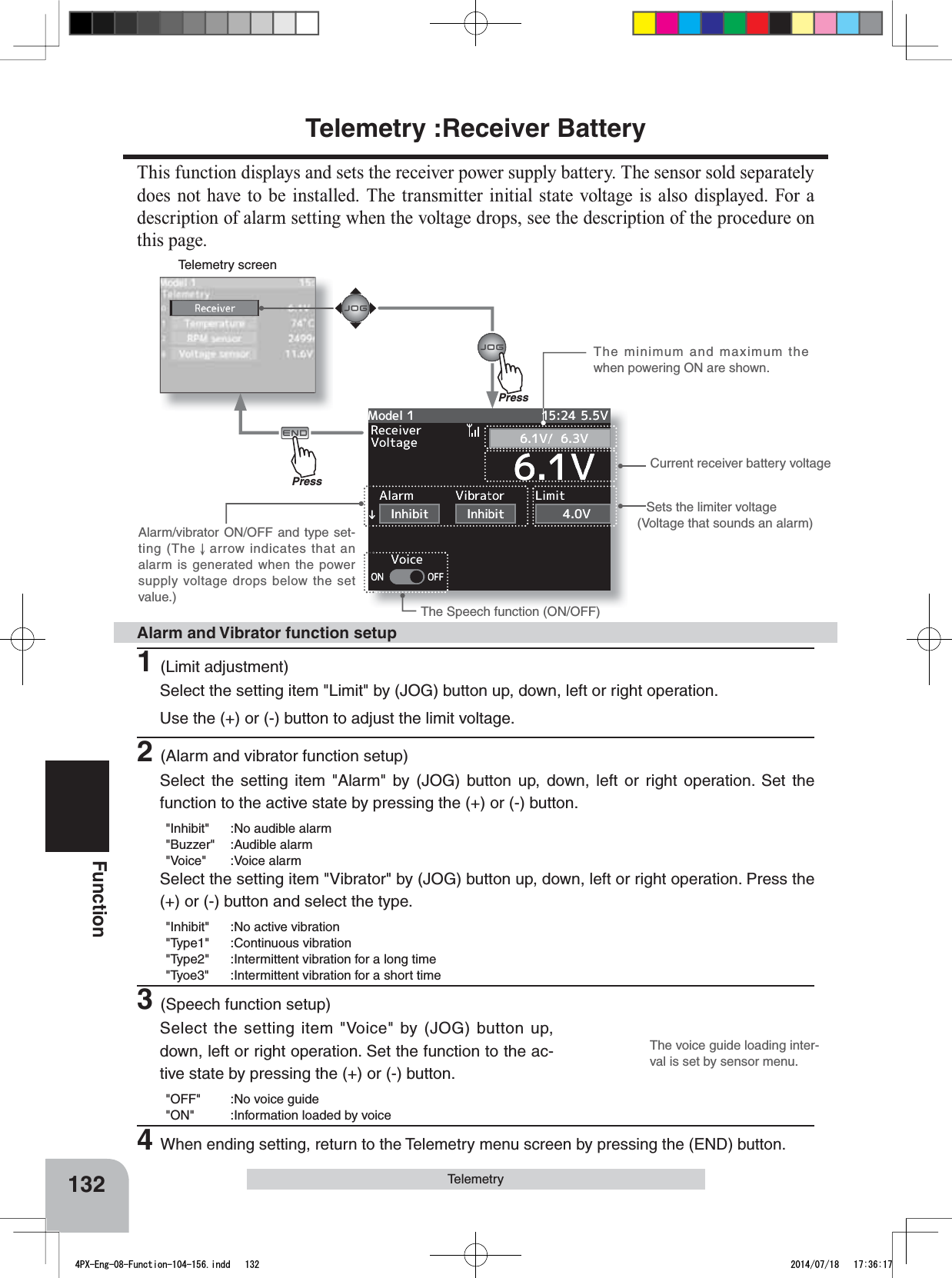
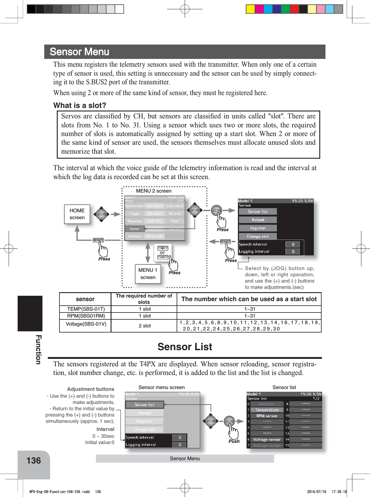
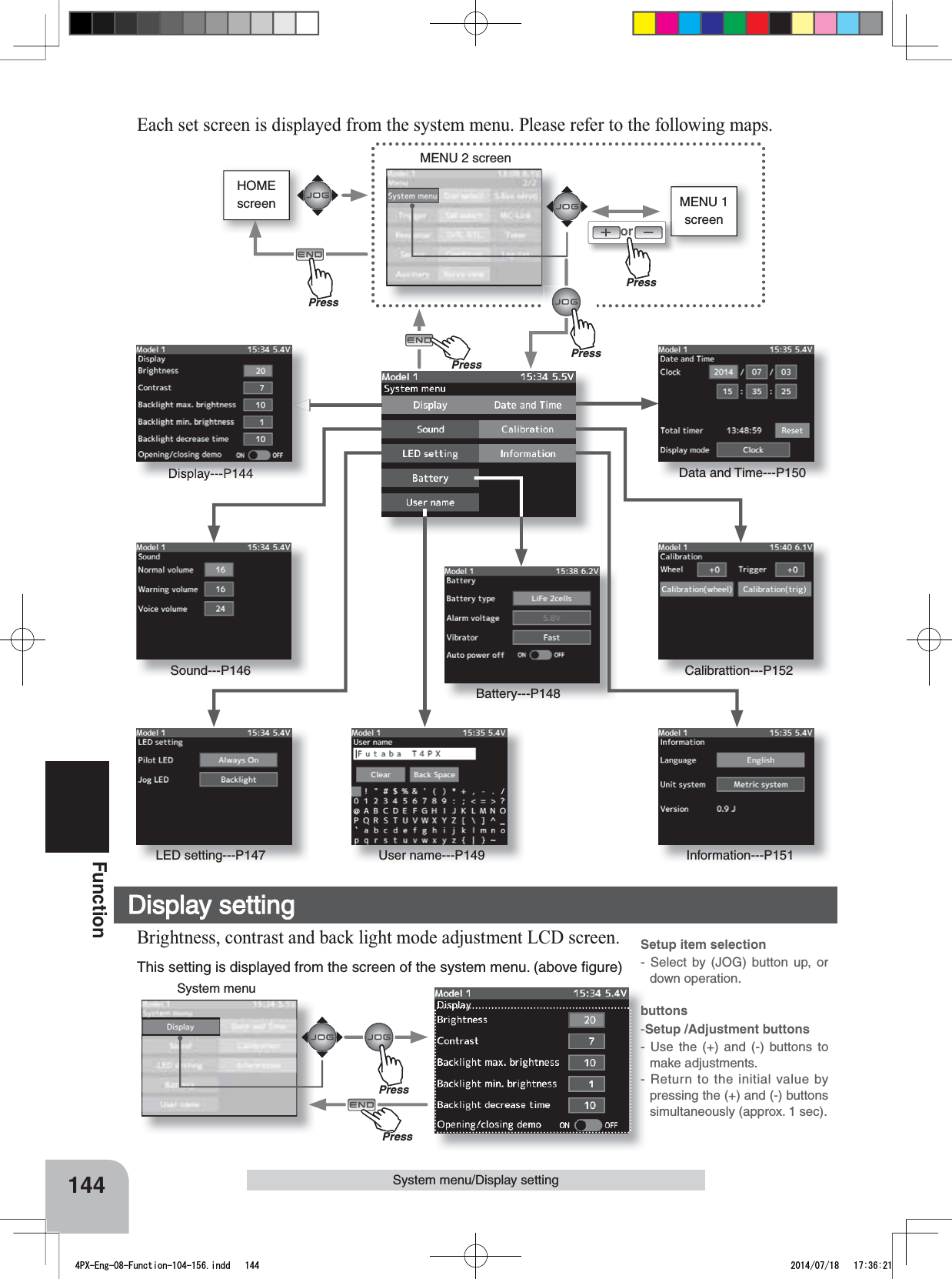
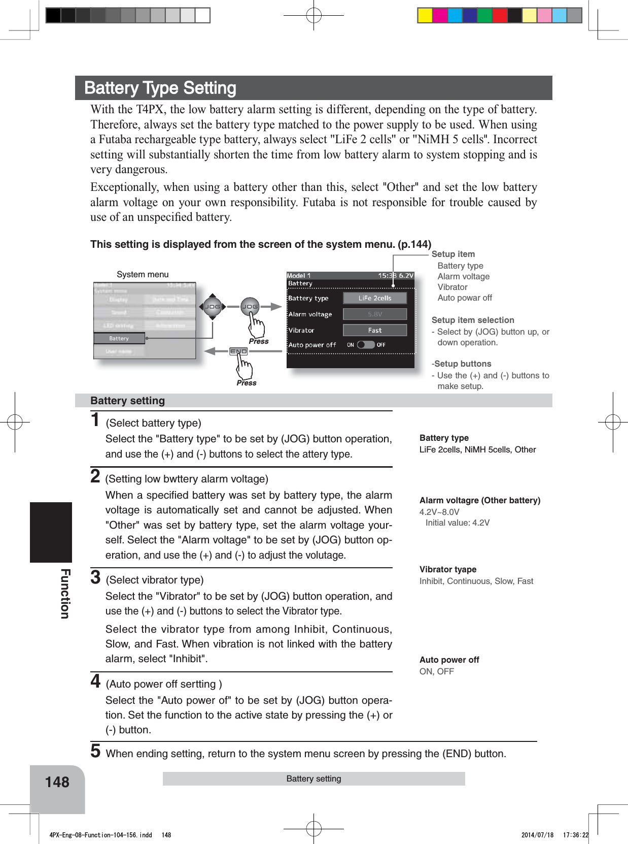
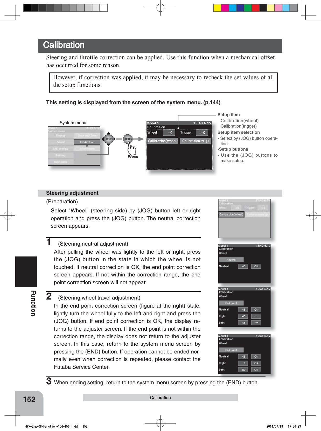
![When using in races in which the lead angle setting function is inhibited by the ESC, set "Lead angle use" to "INH". The "Lead angle use" setting has priority over "Turbo mode". If "Lead angle use" is set to "INH", the lead angle setting function can be turned off even if "Turbo mode" is set to "Turbo1" or "Turbo2".The MC940,960CR shows that the lead angle setting function is OFF ("0" timing) by blinking a LED.The "Lead angle" and "Point A, B, C, D, E Lead angle" relationship is shown on the graphs below. Graph [1] shows the relationship when the same value is set at "Points A, B, C, D, E Lead angle" of [1] and [2] and the "Lead angle" was set to "0" and graph [2] shows the relationship when a value other than "0" was set at "Lead angle". As shown in the graphs, [2] is added to the "Points A, B, C, D, E Lead angle" set lead angle and [1] is added to the "Lead angle" set lead angle. For example, if "3" is set at Point A and "Lead angle" of [2] is set to "2", the actual Point A becomes 3+2=5 (deg). Since "Lead angle" of [A] is "0", the actual Point A also becomes 3+0=3 (deg).A B C D EABCDE1 (Lead angle ="0") Lead Angle(deg)rpmTurn on "Lead angle use"A B C D EA基準進角BCDE2 (Lead angle >"0") Lead Angle(deg)rpmLeadangle125FunctionMC Link Function (ESC Link)Lead angle useMC940,960CR :ACT/INHSame as Link software Lead Angle Use.This function is effective when Turbo Mode is Turbo1 or Turbo2 and sets whether or not lead angle is used. This setting has priority over the Turbo Mode setting. When using in races in which the lead angle function is inhib-ited by the ESC set this function to INH.INH : Lead angle function not used.ACT : Lead angle usedLead angleMC940,960CR :0deg~59degSame as Link software Lead Angle.When "Lead Angle Use" is turned on the motor lead angle can be set at the MC960CR. The lead angle can be set up to 59 degrees in 1 degree incre-ments.Point A,B,C,D,E Lead angleMC940,960CR :0deg~59degSame as Link software Boost Angle.Point A,B,C,D,E RotationMC940,960CR :0rpm~99990rpmSame as Link software Boost Angle rpm.When "Lead Angle Use" is turned on the lead angle versus motor speed of the 5 points A to E can be set. The lead angle can be set up to 59 degrees in 1 degree increments.4PX-Eng-08-Function-104-156.indd 125 2014/07/18 17:36:15](https://usermanual.wiki/Futaba/T4PX-24G.User-Manual-Part-3-Page-112-163/User-Guide-2346281-Page-14.png)
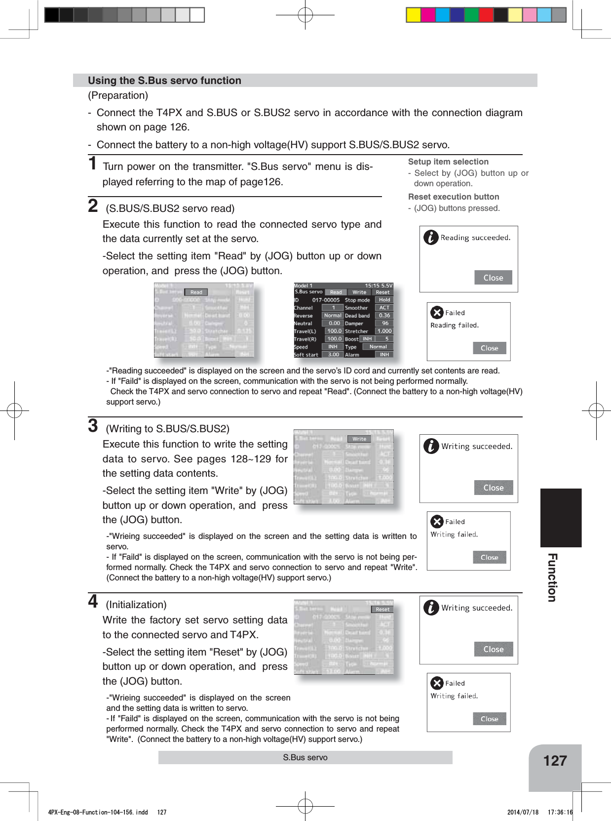
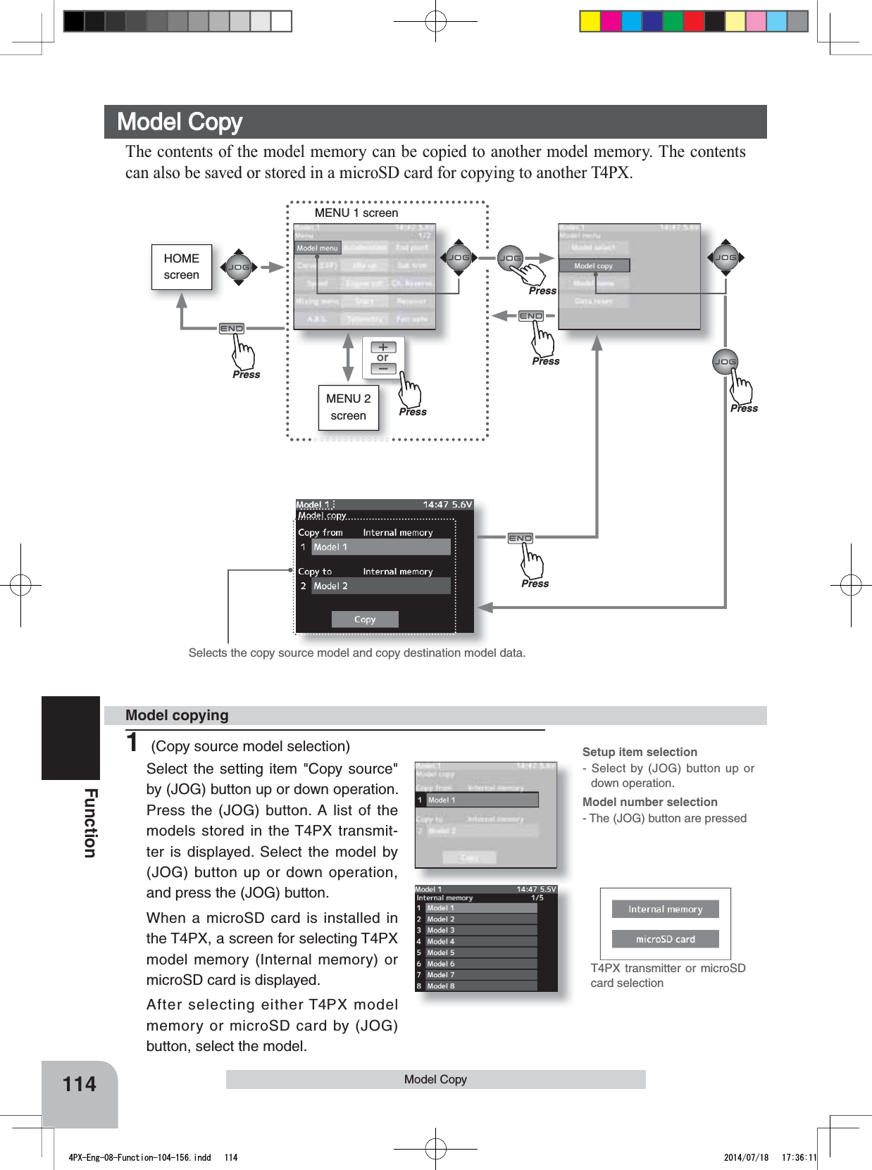
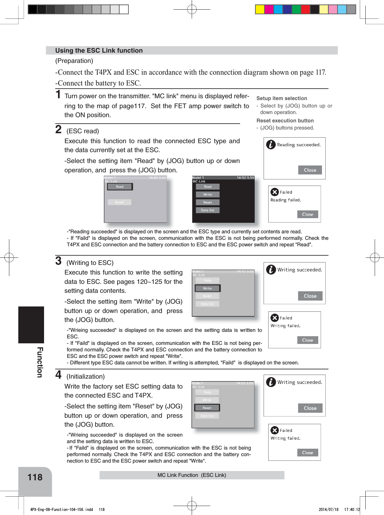
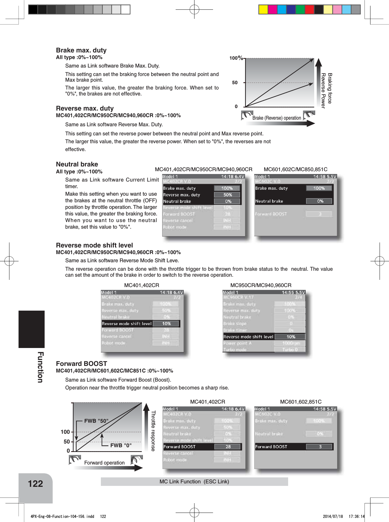
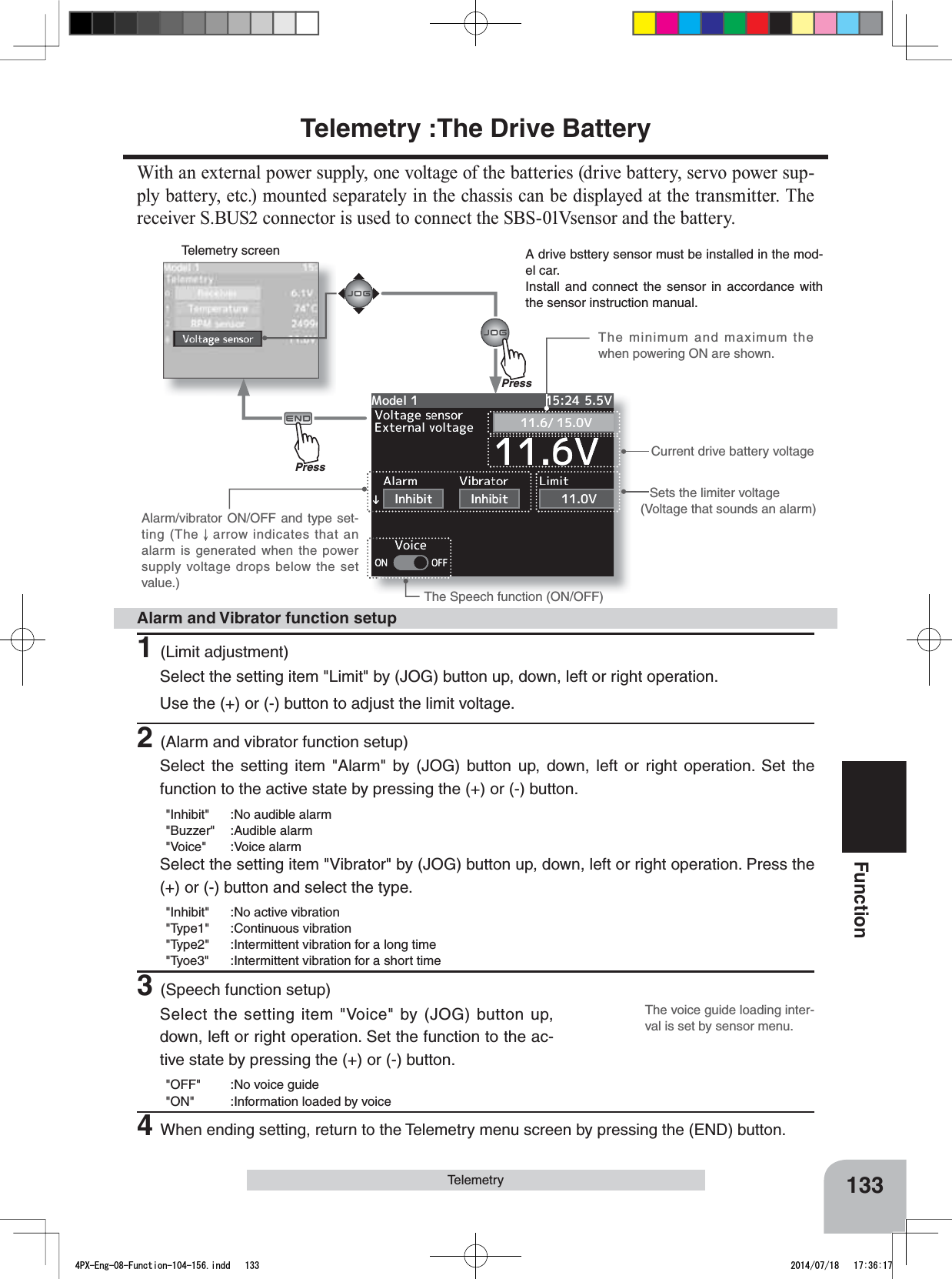
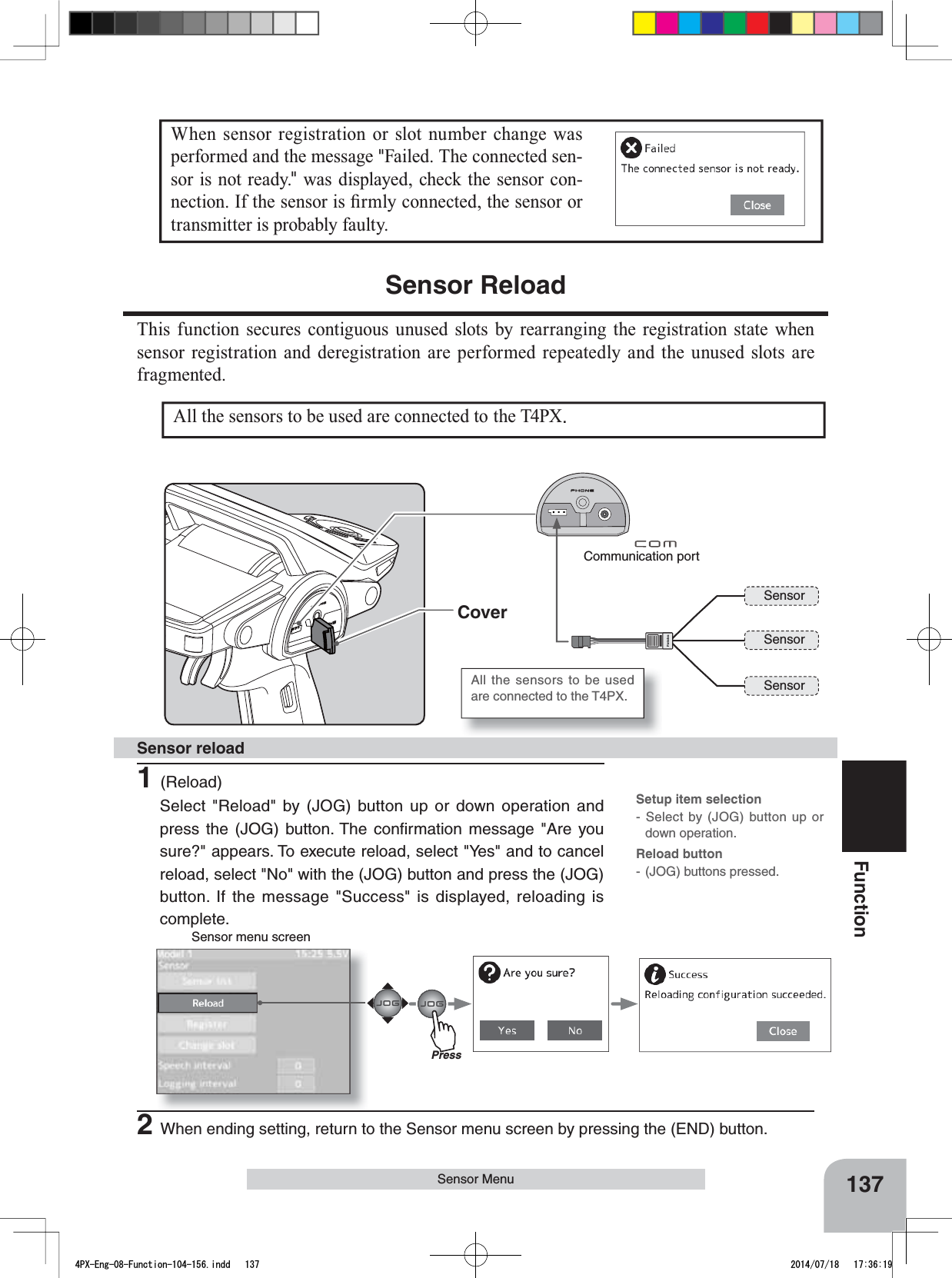
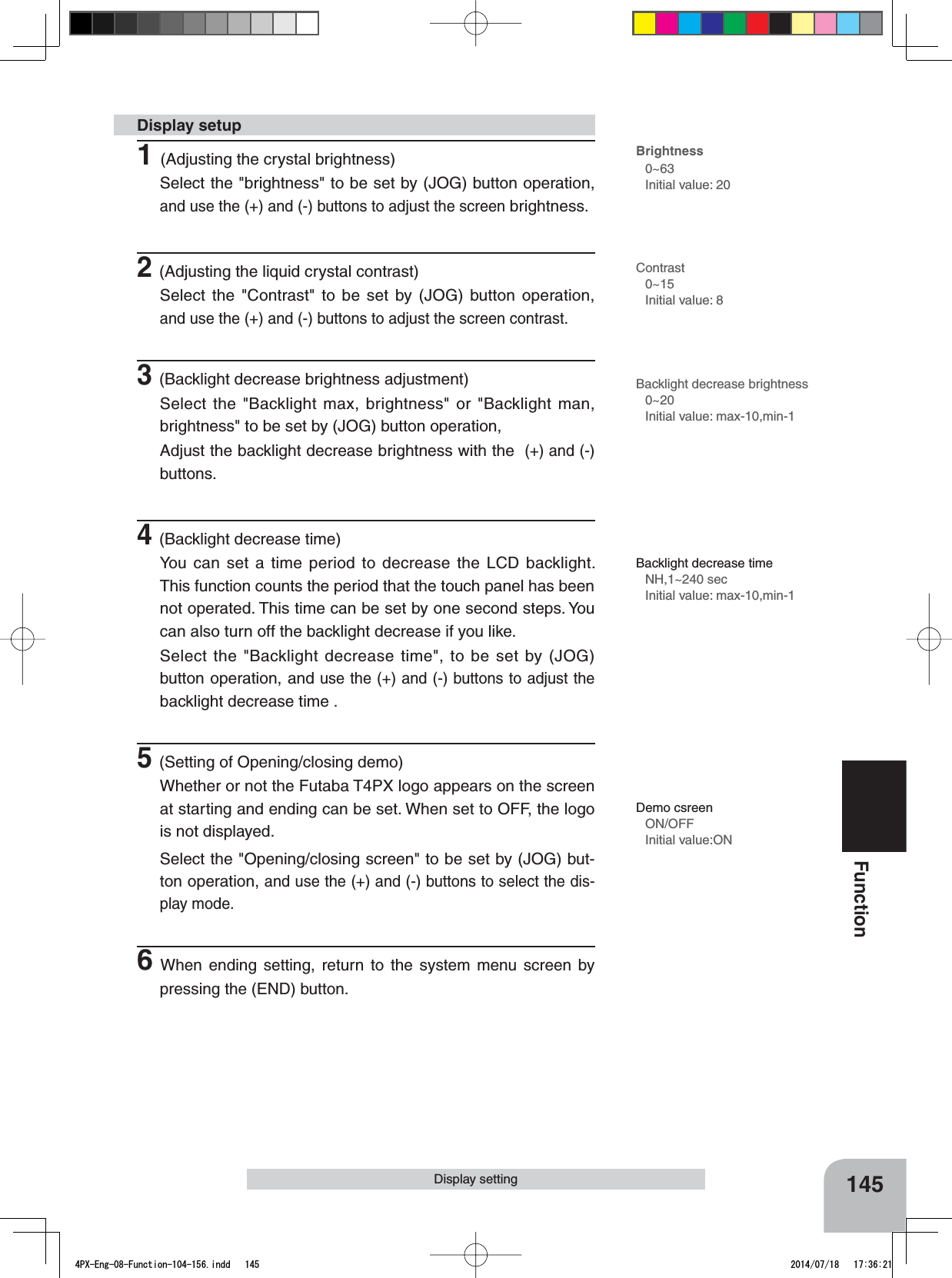
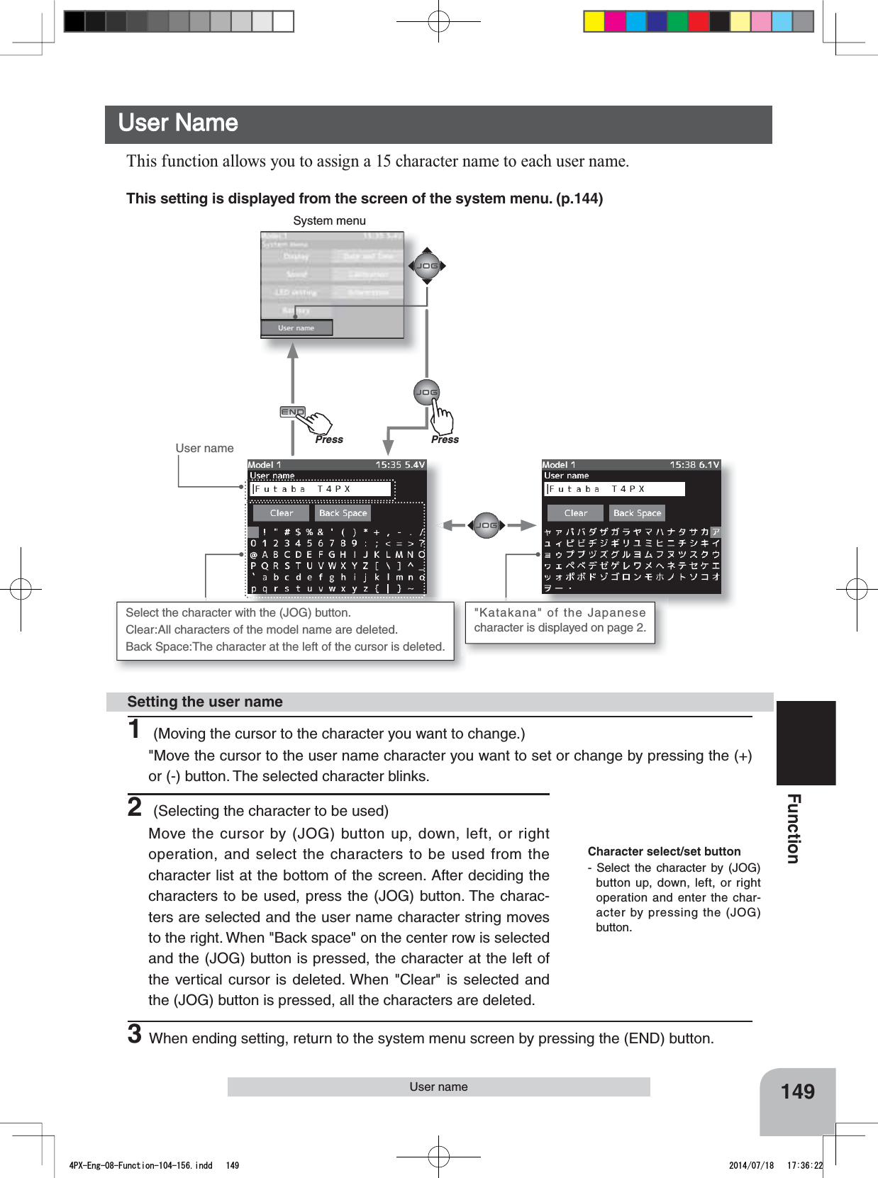
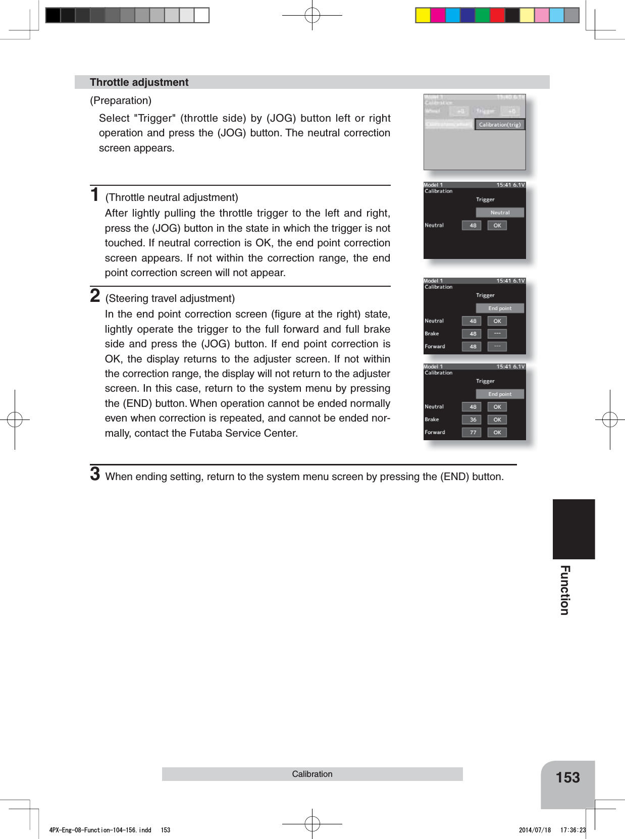
![128FunctionS.Bus ServoS.BUS function setup(Preparation)6%866%86VHUYRLVUHDGUHIHUULQJWRWKHH[SODQDWLRQRISDJH1Select the setting item by (JOG) button up, down, left, or right operation.Set the value by (+) and (-) button.IDDisplays the ID of the servo whose parameters are to be read. It cannot be changed.ChannelThis is the S.BUS system channel assigned to the servo. When connected to the receiver S-BUS2 connector as an S.BUS sys-tem, the channel used by the transmitter is assigned. When the normal receiver channel is used, channel setting is unneces-sary.ReverseThe direction in which the servo rotates can be changed.NeutralThe neutral position can be changed. When the eutral offset is large value, the servo’s range of travel is restricted on one side.Travel(L)The maximum left travels centered about the neutral position can be set independently.Travel(R)The maximum right travels centered about the neutral position can be set independently.SpeedSpeeds can be matched by specifying the operating speed. The speed of multiple servos can be matched without be-ing affected by motor fluctuations. This is effective for load torques below the maximum torque.However, note that the maximum speed will not be exceed what the servo is capable of even if the servos operating voltage is increased.Soft StartRestricts operation in the specified direction the instant the power is turned on. By using this setting, the first initial movement when the power is turned on slowly moves the servo to the specified position.Stop ModeThe state of the servo when the servo input signal is lost can be specified. The "Hold" mode setting holds the servo in its last commanded position even if using AM or FM system.SmootherThis function makes servo operation smooth. Set it according to your taste. Normally set it to "ACT". Set it to "INH" when want especially quick operation. When the smoother function was set to "ACT" and the servo was operated the distance up to the target position is hanged in steps so movement is smooth.Dead bandThe dead band angle at stopping can be specified.[Relationship between dead band set value and servo operation]Small - Dead band angle is small and the servo is immediately operated by a small signal change.Large - Dead band angle is large and the servo does not operate at small signal changes.(Note) If the dead band angle is too small, the servo will operate continuously and the current consumption will in-crease and the life of the servo will be shortened.4PX-Eng-08-Function-104-156.indd 128 2014/07/18 17:36:16](https://usermanual.wiki/Futaba/T4PX-24G.User-Manual-Part-3-Page-112-163/User-Guide-2346281-Page-17.png)
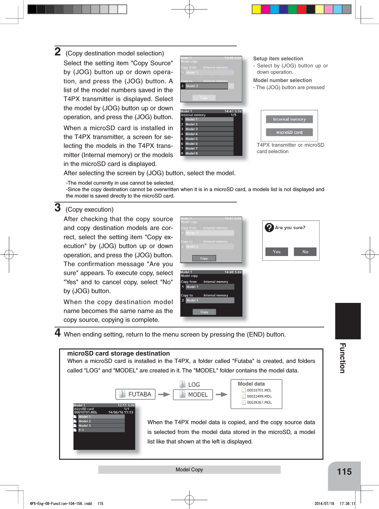
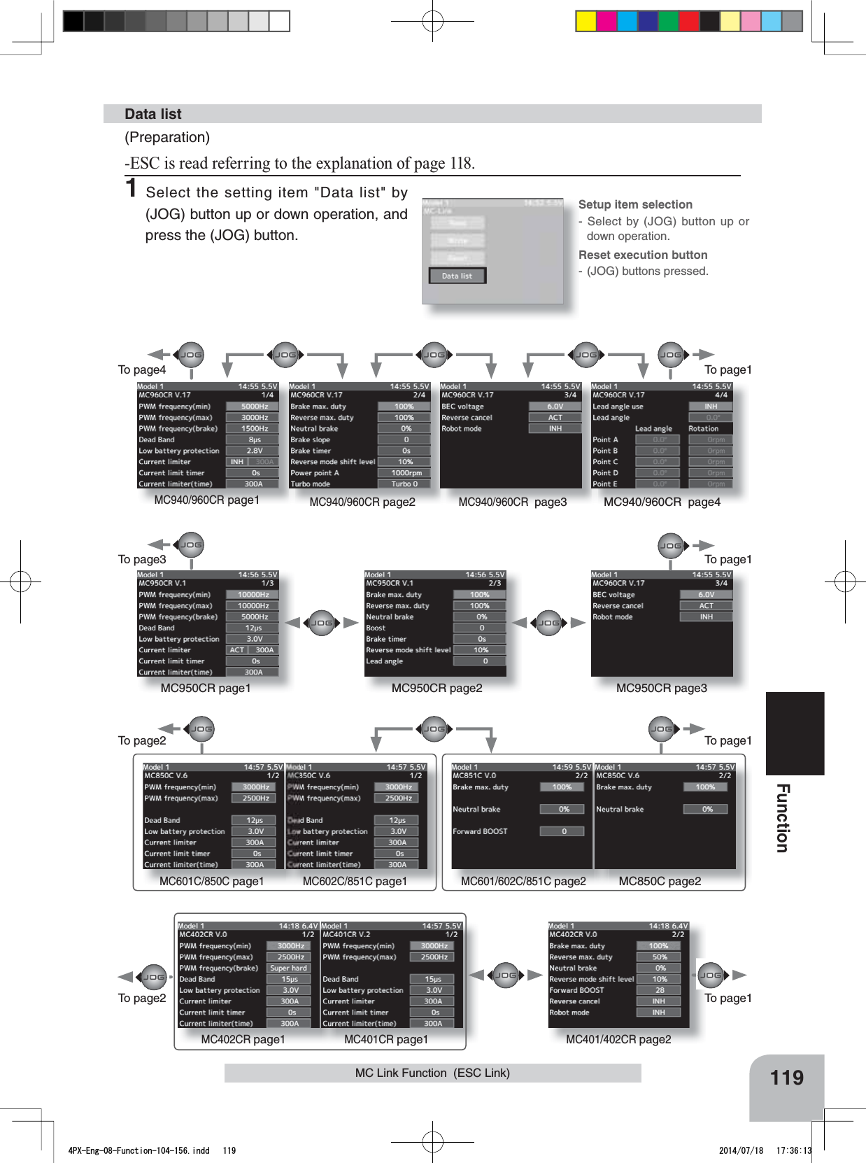
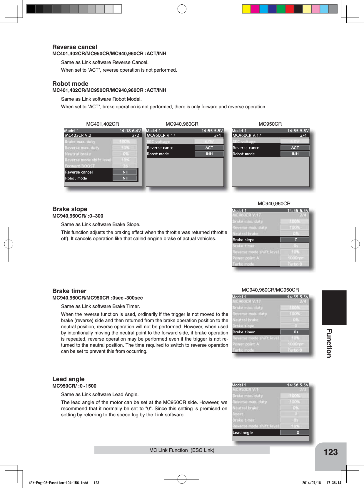
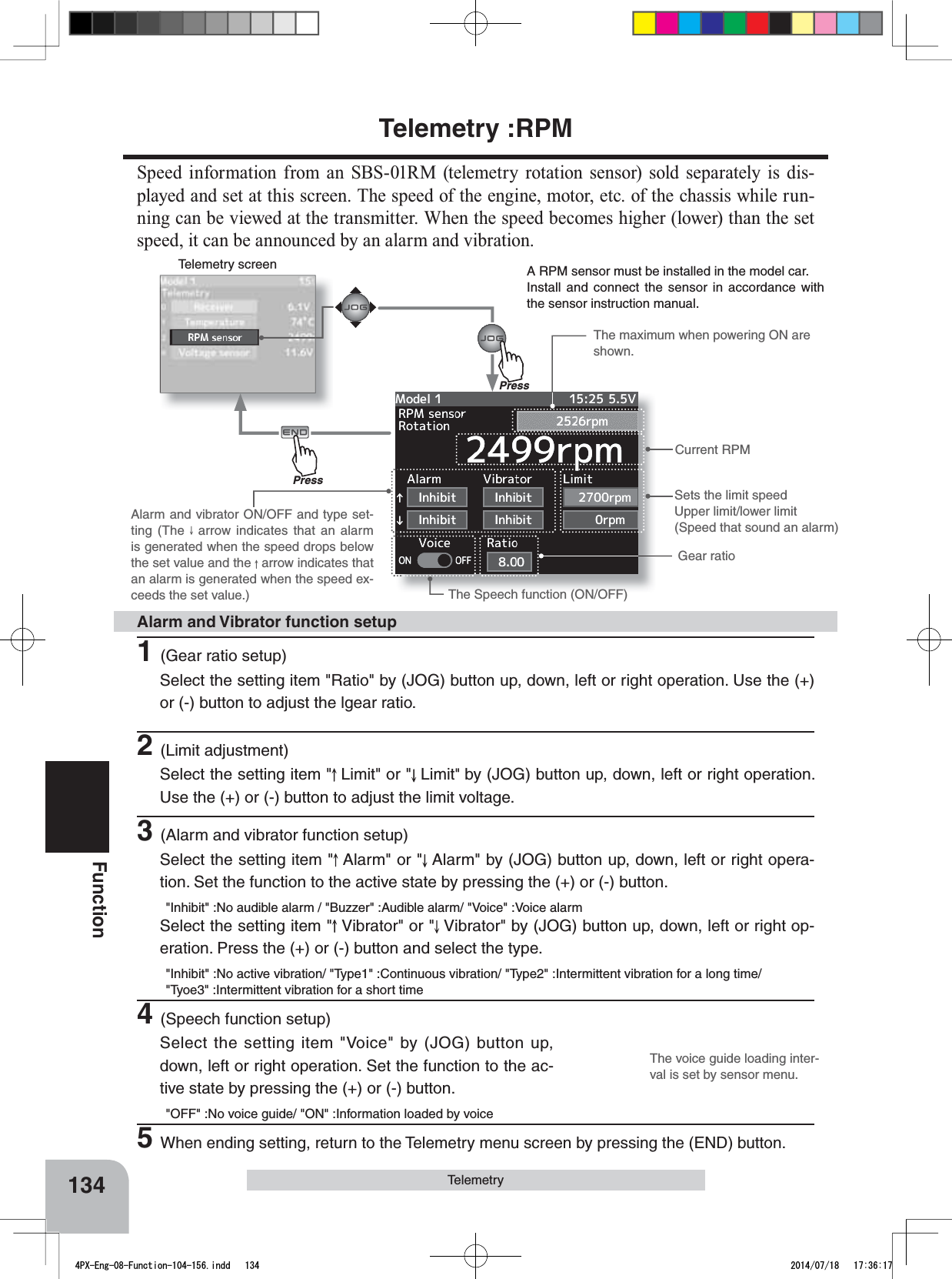
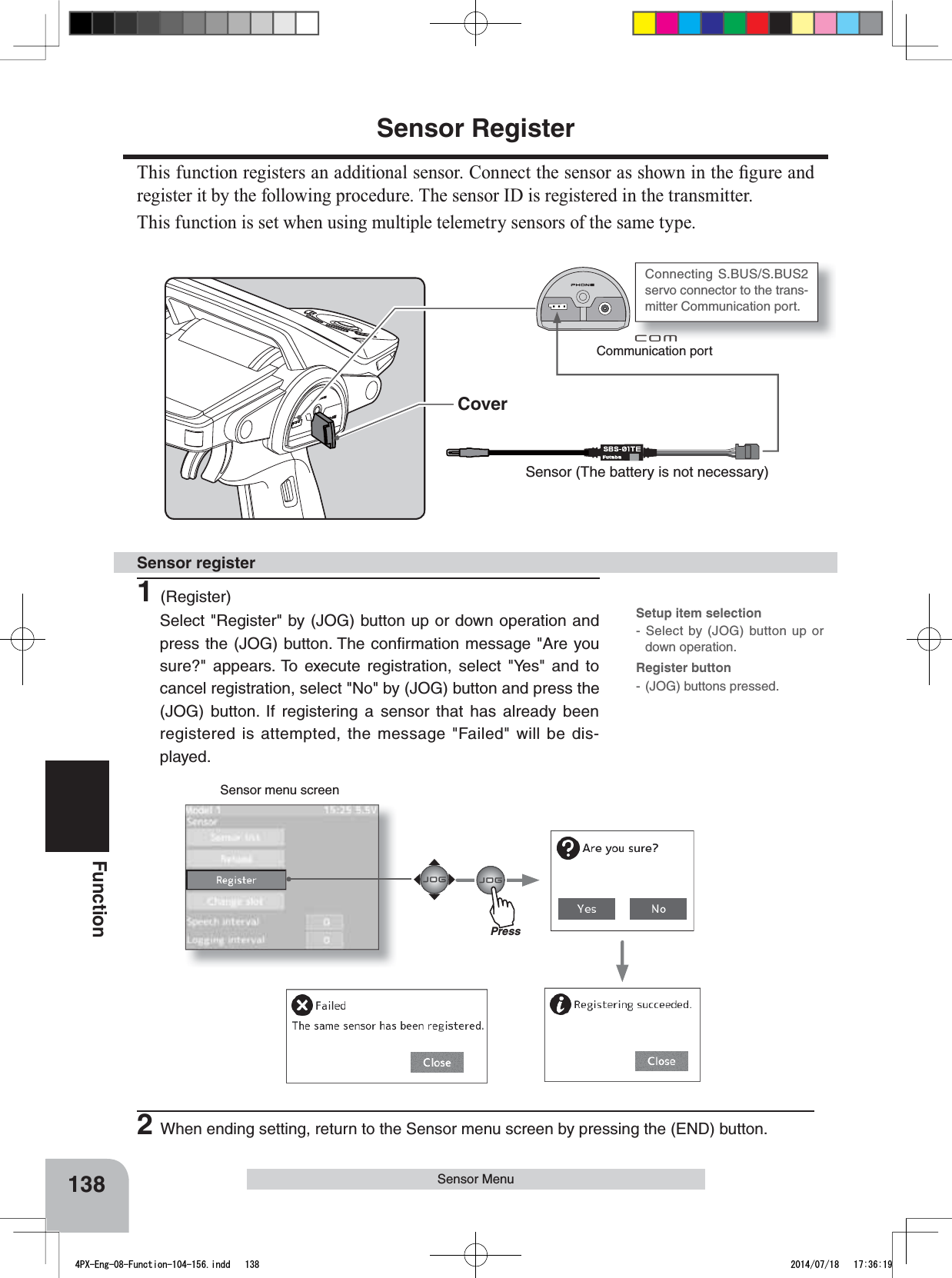
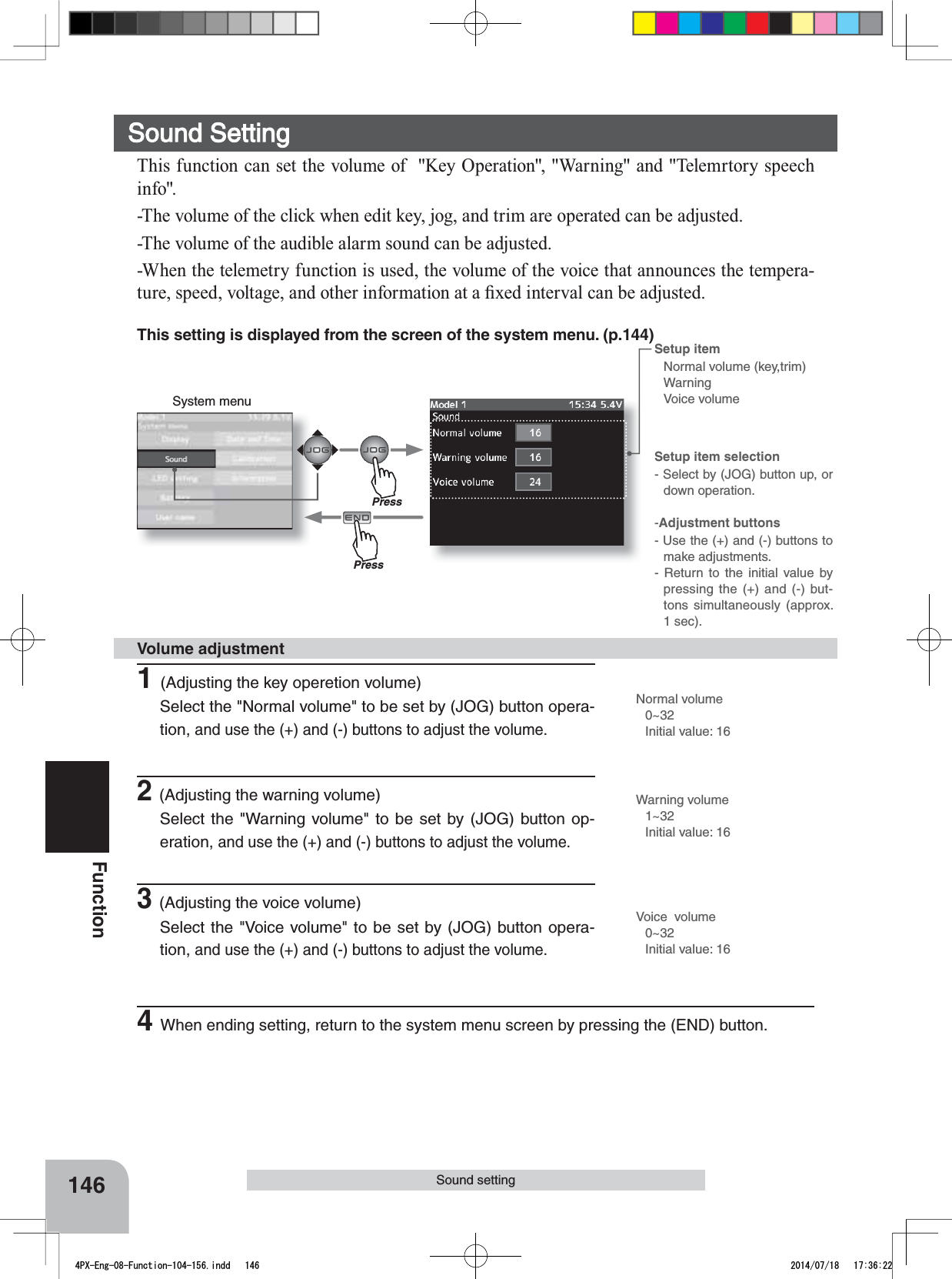
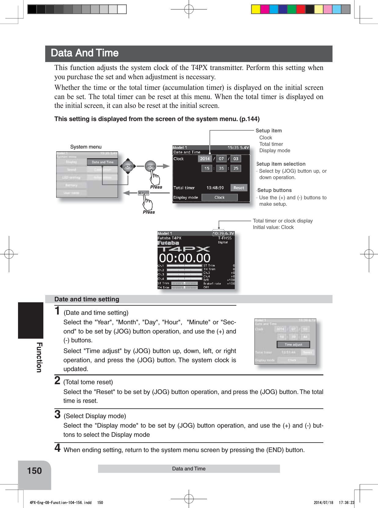
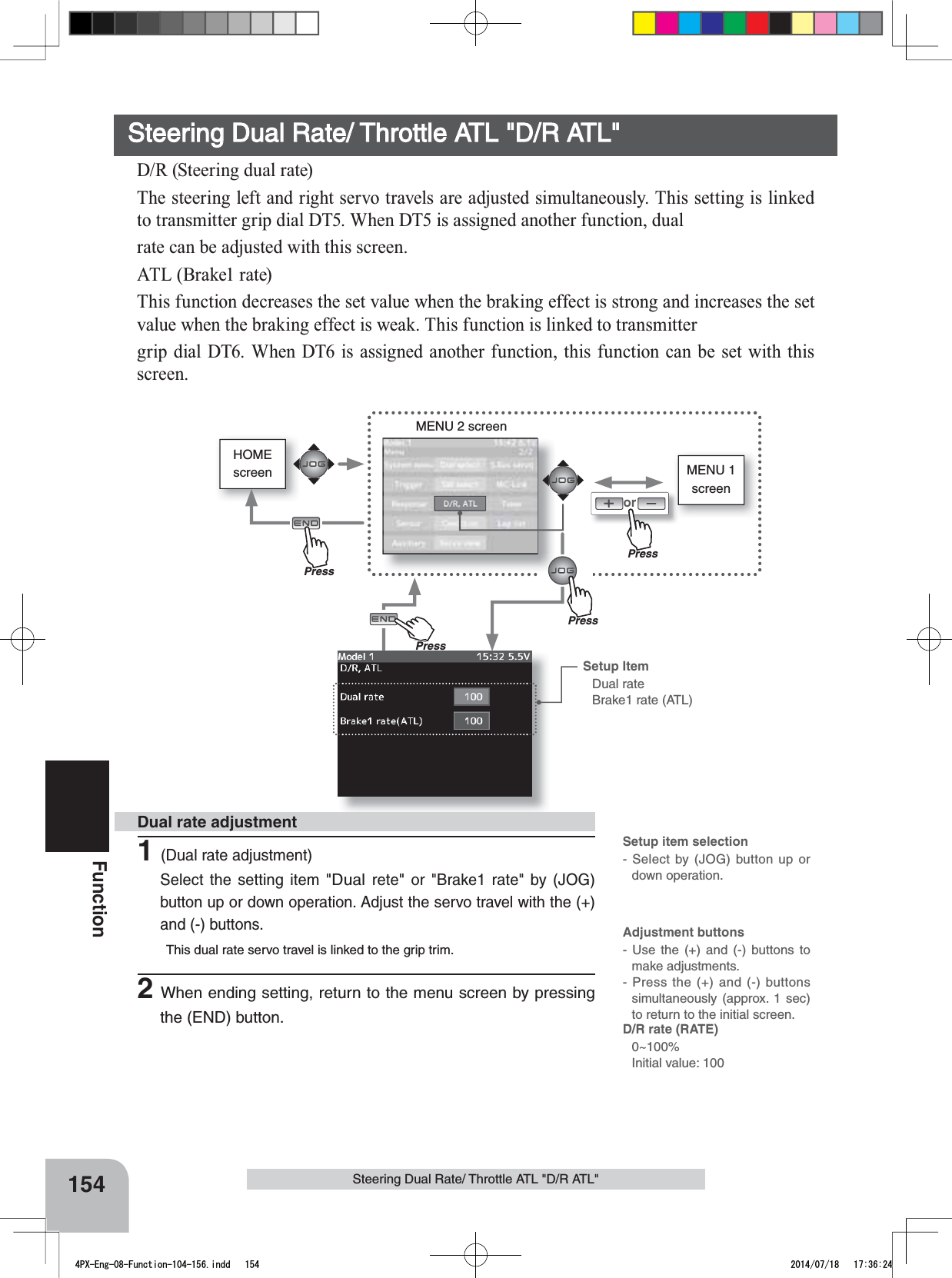
![129FunctionS.Bus ServoDamperThe characteristic when the servo is stopped can be set.When smaller than the standard value, the characteristic becomes an overshoot characteristic. If the value is larger than the standard value, the brake is applied before the stop position.Especially, when a large load is applied, overshoot, etc. are suppressed by inertia and hunting may occur, depend-ing on the conditions. If hunting (phenomena which cause the servo to oscillate) occurs even though the Dead Band, Stretcher, Boost and other parameters are suitable, adjust this parameter to a value larger than the initial value.[Relationship between damper set value and servo operation]Small - When you want to overshoot. Set so that hunting does not occur.Large - When you want to operate so that braking is not applied. However, it will feel like the servo response has wors-ened.(Note) If used in the hunting state, not only will the current consumption increase, but the life of theservo will also be shortened.StretcherThe servo hold characteristic can be set. The torque which attempts to return the servo to the target position when the current servo position has deviated from the target position can be adjusted.This is used when stopping hunting, etc., but the holding characteristic changes as shown below.[Relationship between stretcher and servo operation]Small - Servo holding force becomes weaker.Large - Servo holding force becomes stronger.(Note) When this parameter is large, the current consumption increasesBoost/Boost (ON/OFF)INH : It is the boost ON at the time of low-speed operation.(In the case of usual)ACT : It is always the boost ON.(When quick operation is hope)The minimum current applied to the internal motor when starting the servo can be set. Since a small travel does not start the motor, it essentially feels like the dead band was expanded. The motor can be immediately started by adjust-ing the minimum current which can start the motor.[Relationship between boost set value and servo operation]Small - Motor reacts to a minute current and operation becomes smooth.Large - Initial response improves and output torque increases. However, if the torque is too large, operation will be-come rough.TypeWhen "Retractable" is selected and the servo has been continuously stopped for 30 seconds, the deadband expands and unnecessary hold current due to external force is eliminated. When a new controlsignal enters, normal operation is resumed. When using the servo as a landing gear servo, select"Retractable". Also adjust the servo travel to match the landing gear movement range.AlarmWhen the power supply of a servo is previously turned on at the time of a power supply injection without taking trans-mit of a transmitter, the buzzer sound of about 2.5 Hz continues sounding from a servo.(Even when the transmit of a transmitter is taken out previously, a buzzer becomes until the signal of a servo is output-ted normally, but it is not unusual.)The transmitter has been turned OFF ahead of a servo power supply The buzzer sound of about 1.25 Hz continues sounding as servo power supply end failure alarm.(Do not insert or remove the servo connector while the receiver power is ON. A buzzer may sound by incorrect recog-nition.)*Buzzer sound is generated by vibrating the motor of a servo.Since current is consumed and a servo generates heat, please do not operate the number more than needed or do not continue sounding a buzzer for a long time.4PX-Eng-08-Function-104-156.indd 129 2014/07/18 17:36:16](https://usermanual.wiki/Futaba/T4PX-24G.User-Manual-Part-3-Page-112-163/User-Guide-2346281-Page-18.png)
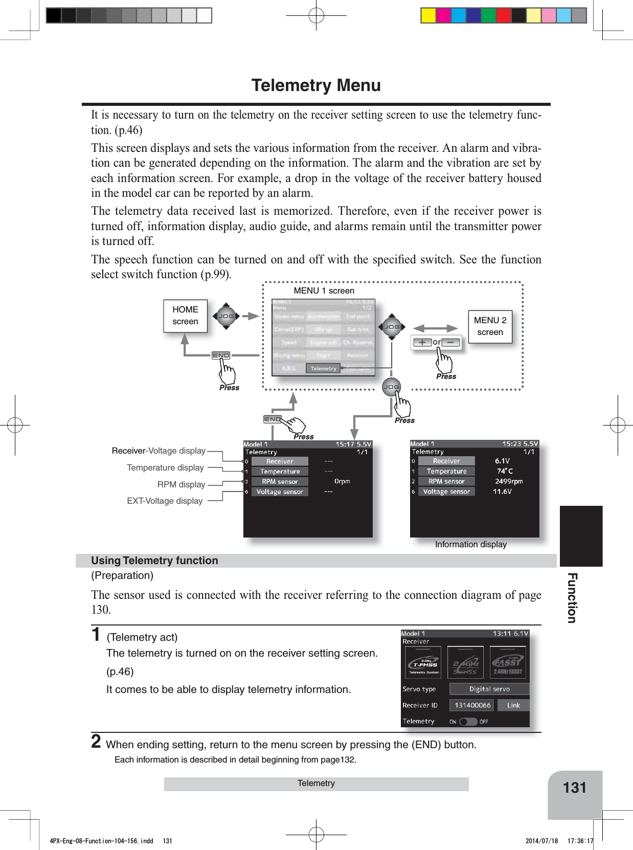
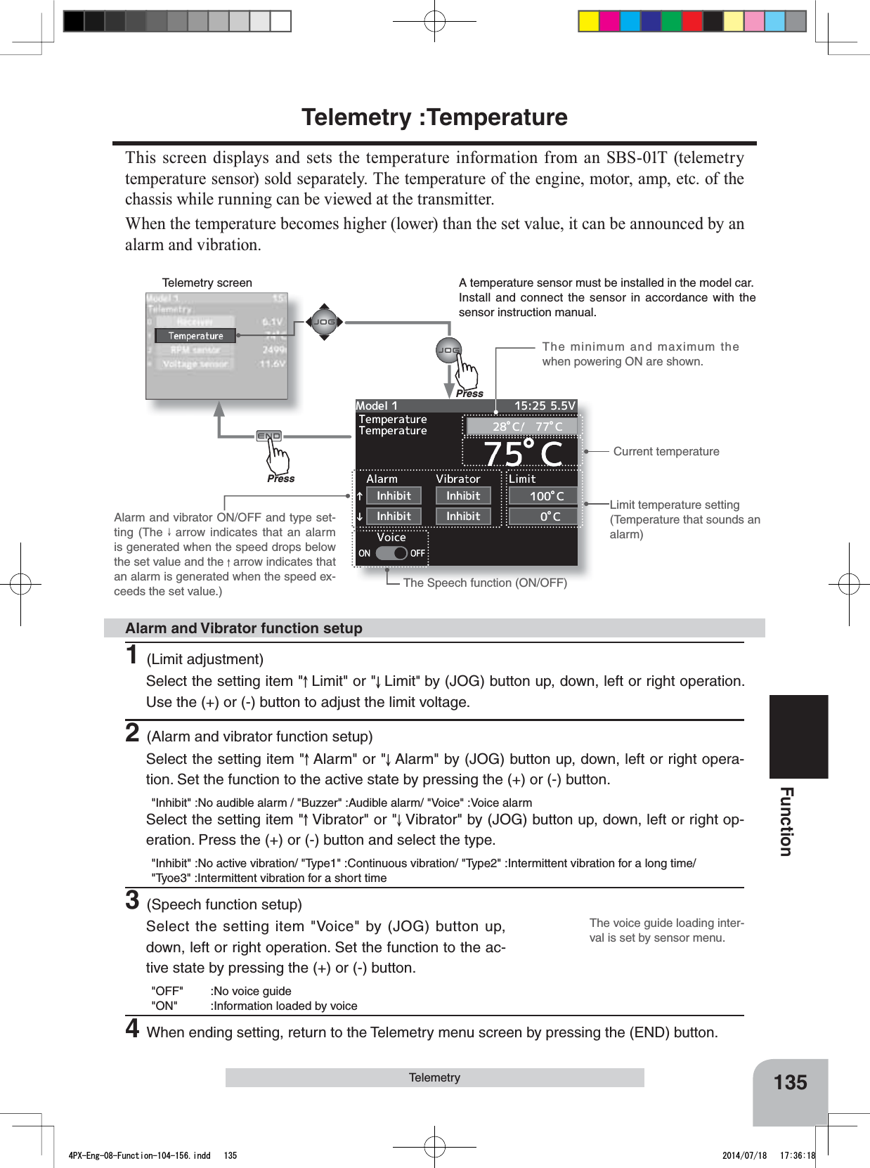
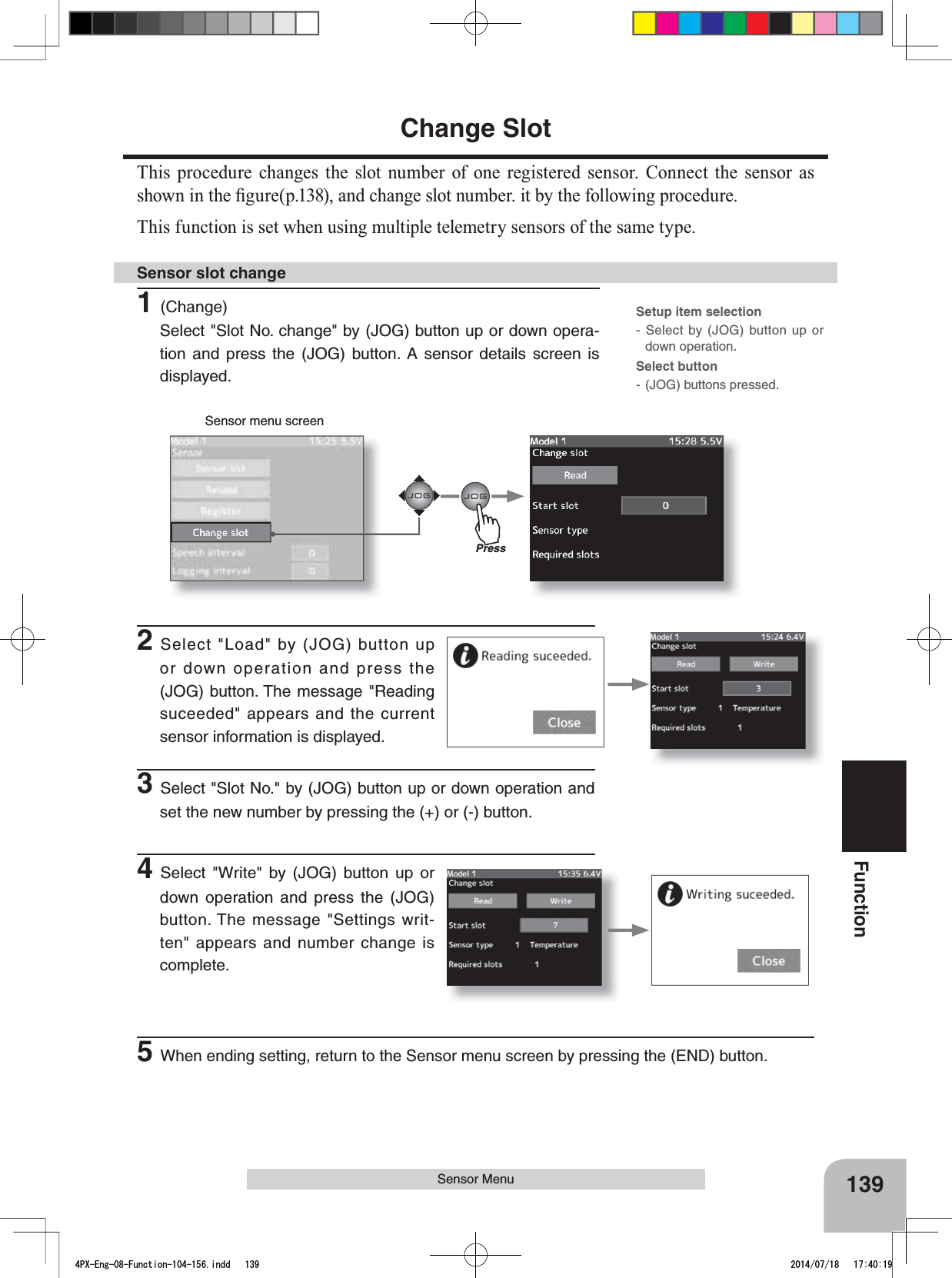
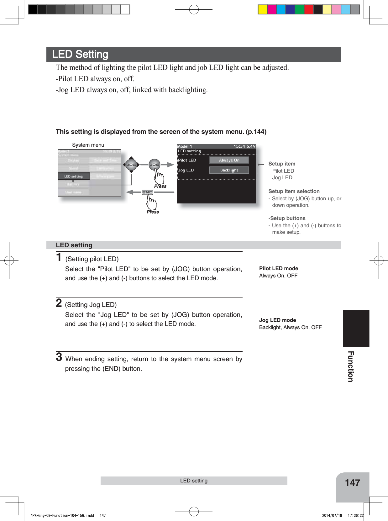
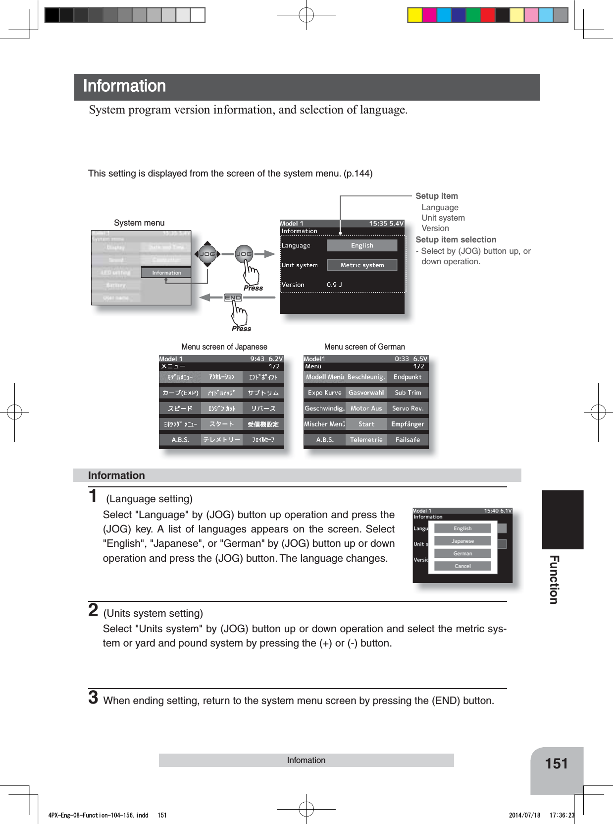
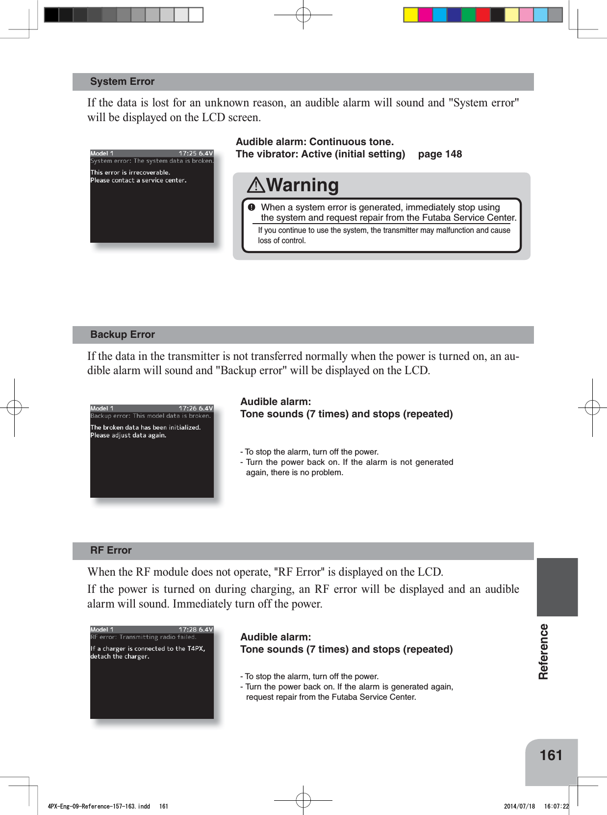
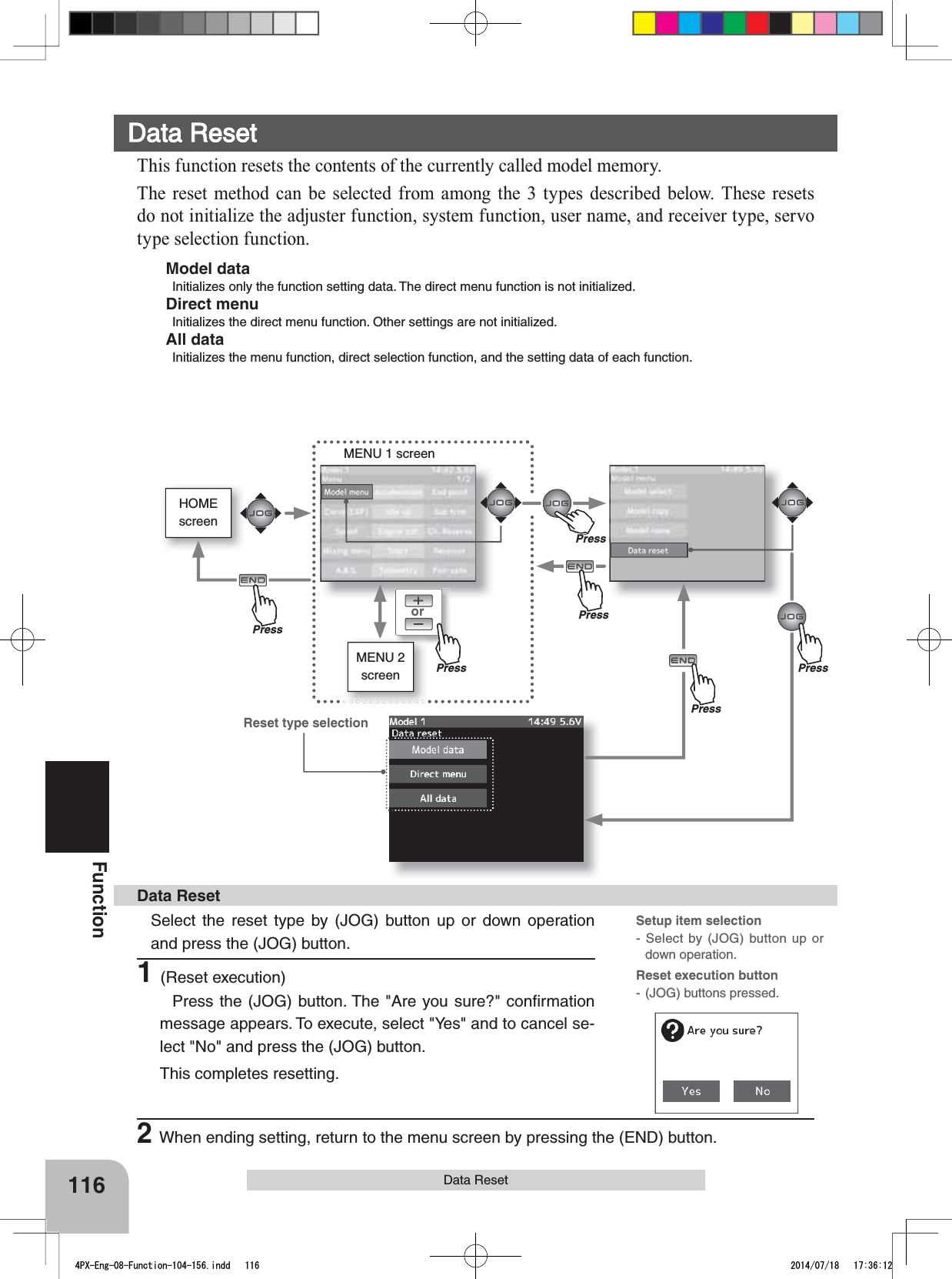
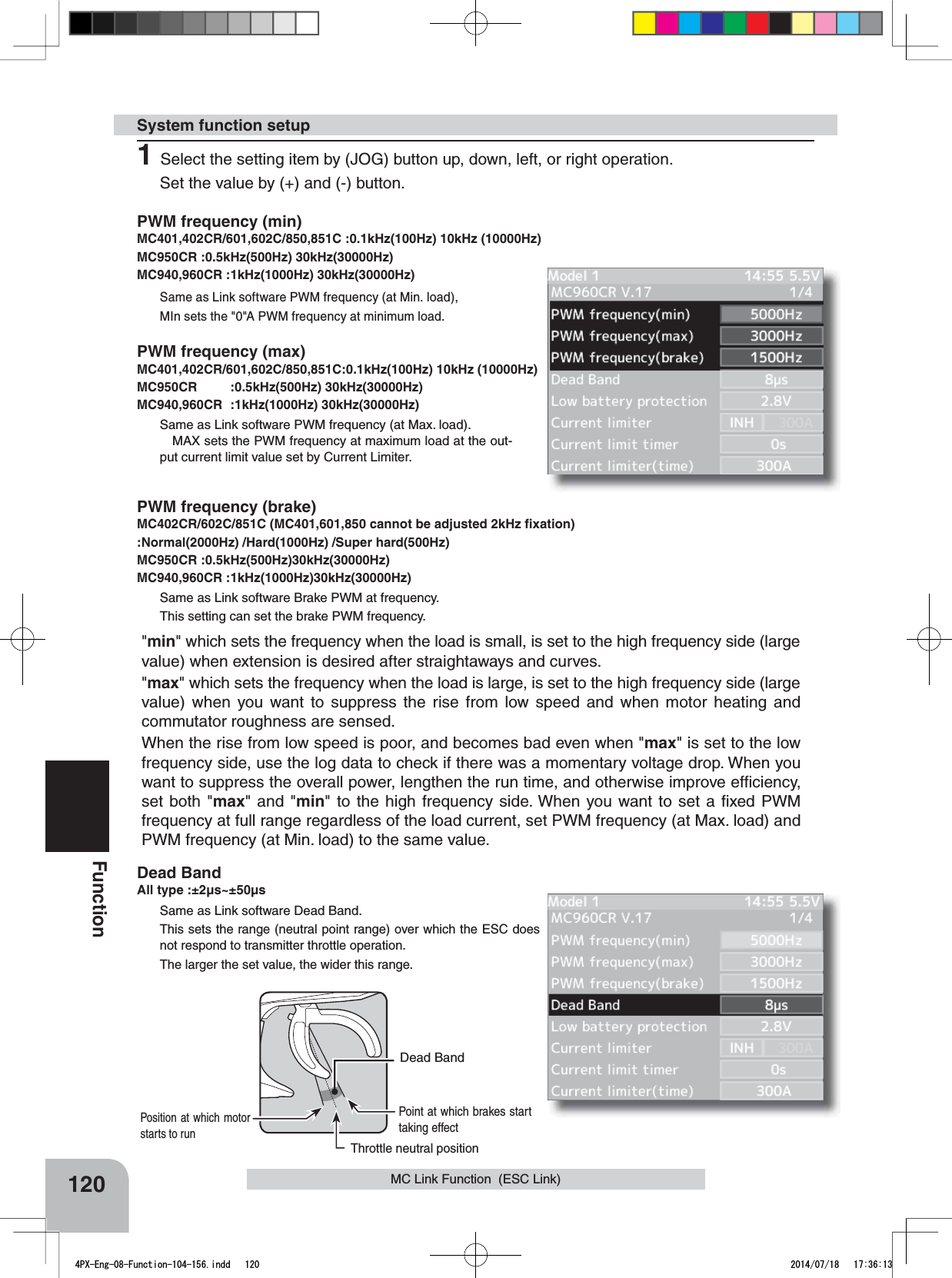
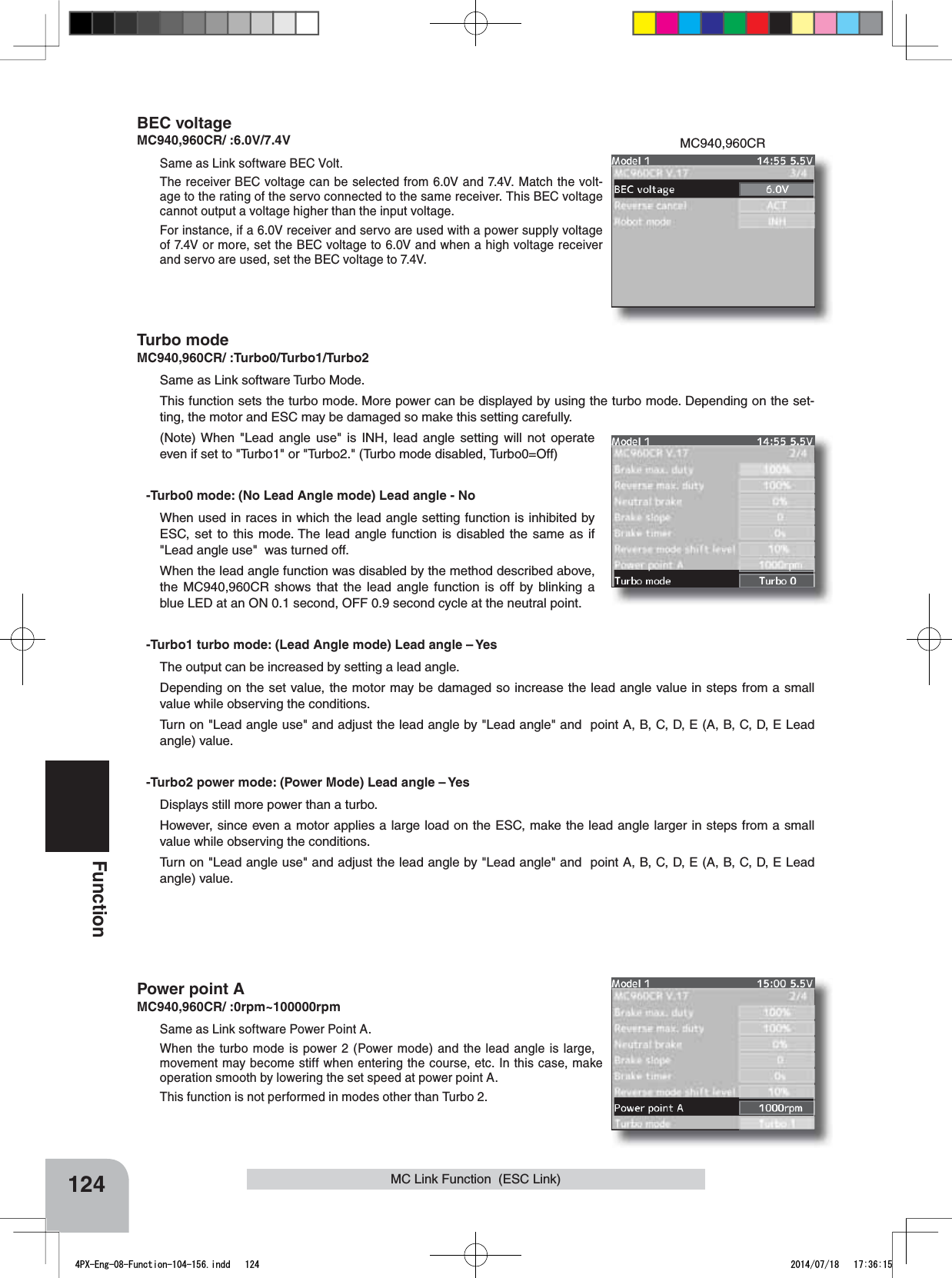
![160Reference- If the alarm is not reset, the auto power off function will auto-matically turn off the power after 5 minutes. - The alarm stops even if the (JOG) button is pressed. However, check the function switch. Audible alarm: Tone sounds (7 times) and stops (repeated)Warning DisplaysLow Battery AlarmPower off forgotten alarm,IWKHWUDQVPLWWHUEDWWHU\YROWDJHGURSVEHORZWKHXVDEOHUDQJHDQDXGLEOHDODUPZLOOVRXQGDQG/RZEDWWHU\ZLOOEHGLVSOD\HG6LQFHWKHXVDEOHUDQJHRI/L)HDQG1L0+EDWWHULHVDQG/L)HEDWWHULHVLVGLIIHUHQWWKHSRZHUVXSSO\XVHGPXVWEHVHWE\V\VWHPVHWWLQJS$W 73; LQLWLDOL]DWLRQ LI VWHHULQJ ZKHHO WKURWWOH WULJJHU SXVKVZLWFKHGLWEXWWRQRURWKHURSHUDWLRQLVQRWSHUIRUPHGZLWKLQPLQXWHVDQDXGLEOHDODUPZLOOVRXQGDQGWKHPHVVDJH:DUQLQJ$XWRSRZHURIIZLOODSSHDU,IVWHHULQJZKHHOWKURWWOH WULJJHU SXVK VZLWFK HGLWEXWWRQRURWKHURSHUDWLRQLVSHUIRUPHGWKHDODUPLVUHVHW $OVRWXUQRIIWKHSRZHUZKHQWKHWUDQVPLWWHULVQRWLQXVH,I\RXGRQRWZDQWWRXVHWKLVDODUPDQGWKHDXWRSRZHURIIIXQFWLRQWKH\FDQEHGLVDEOHGE\V\VWHPVHWWLQJSAudible alarm: Continuous tone. The vibrator: Active (initial setting) page 148WarningWhen a low battery alarm is generated, cease operation im-mediately and retrieve the model. If the battery goes dead while in operation, you will lose control. MIX Warning:KHQWKHSRZHUVZLWFKLVWXUQHGRQZKLOHWKHLGOHXSHQJLQHFXWRUQHXWUDOEUDNHIXQFWLRQVZLWFKLVRQDQDXGLEOHDODUPZLOOVRXQGDQG:DUQLQJZLOOEHGLVSOD\HGRQWKH/&':KHQWKDWIXQFWLRQVZLWFKLVWXUQHGRIIWKHDODUPZLOOVWRSAudible alarm: Tone sounds (7 times) and stops (repeated) 4PX-Eng-09-Reference-157-163.indd 160 2014/07/18 16:07:22](https://usermanual.wiki/Futaba/T4PX-24G.User-Manual-Part-3-Page-112-163/User-Guide-2346281-Page-49.png)