Futaba T4PX-24G Radio Control User Manual
Futaba Corporation Radio Control
UserManual.wiki
>
Futaba
>
T4PX-24G User Manual
>
User Manual-Part 2 (Page 52-111)
Contents
1.
User Manual-Part 1 (Page 1-51)
2.
User Manual-Part 2 (Page 52-111)
3.
User Manual-Part 3 (Page 112-163)
User Manual-Part 2 (Page 52-111)
Navigation menu
Upload a User Manual
Namespaces
Wiki Guide
HTML
PDF
Info
Views
User Manual
Discussion / Help
Navigation
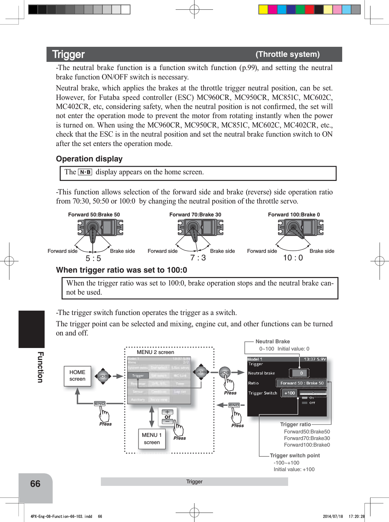
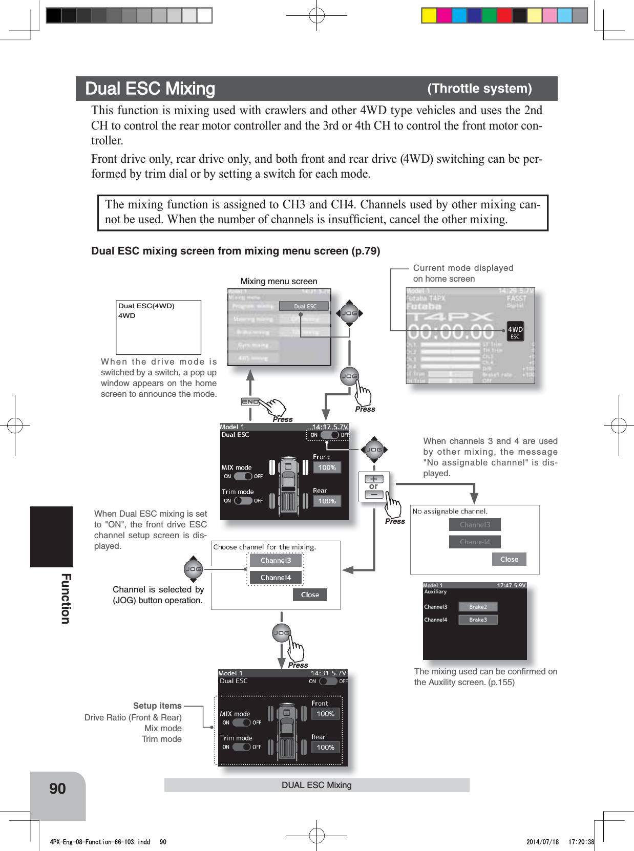

![98FunctionProgram, MixingAAFull rightFull leftA :Zone over which servo does not operate:KHQWKHVWHHULQJVHUYRWUDYHOLVLQVXI¿FLHQWHYHQZKHQ'5LVDQG(QGSRLQWLV140%, programmable mixing can be used to increase the travel somewhat. (Reference data)- Program nixing(1 - 5)->ON- Master channel -> Steering Mixing is applied from steering- Slave channel ->Steering Mixing is applied to steering and the travel is increased.- Mix rate A (left) -> 10% [When subtrim is centered (0%)]- Mix rate B (right) -> 10% [When subtrim is centered (0%)]- Offset -> 0% / - Master mix mode -> ON / - Trim mode -> OFFHowever, the operating range of the servo is exceeded even if a large value is input at "Mix rate A (left)" and "Mix rate B (right)" and a zone over which the servo does not operate even when the wheel is moved to the left or right is created. A zone over which the servo does not operate is also generated at the moving side when the subtrim is moved to the left and right. Therefore, set the "Mix rate A (left)" and "Mix rate B (right)" value by checking servo operation. When Steering and Throttle Travel is Insufficient The mixing amount can be adjusted by using the function dial function. (p.101)Dial / Trim Setting Select the program mixing function ON/OFF switch with the function select switch function. ( p.99) Switch Setting 8(Trim mode setup)Select setup item "Trim mode" by (JOG) button up, down, left, or right operation, and use the (+) or (-) button to select the mixing mode."OFF" :Trim is added."ON" :Trim is removed.Setting buttons- Use the (+) and (-) buttons to make adjustments.Trim modeON, OFF9When ending setting, return to the Mixing menu screen by pressing the (END) button.4PX-Eng-08-Function-66-103.indd 98 2014/07/18 17:20:40](https://usermanual.wiki/Futaba/T4PX-24G.User-Manual-Part-2-Page-52-111/User-Guide-2346280-Page-47.png)
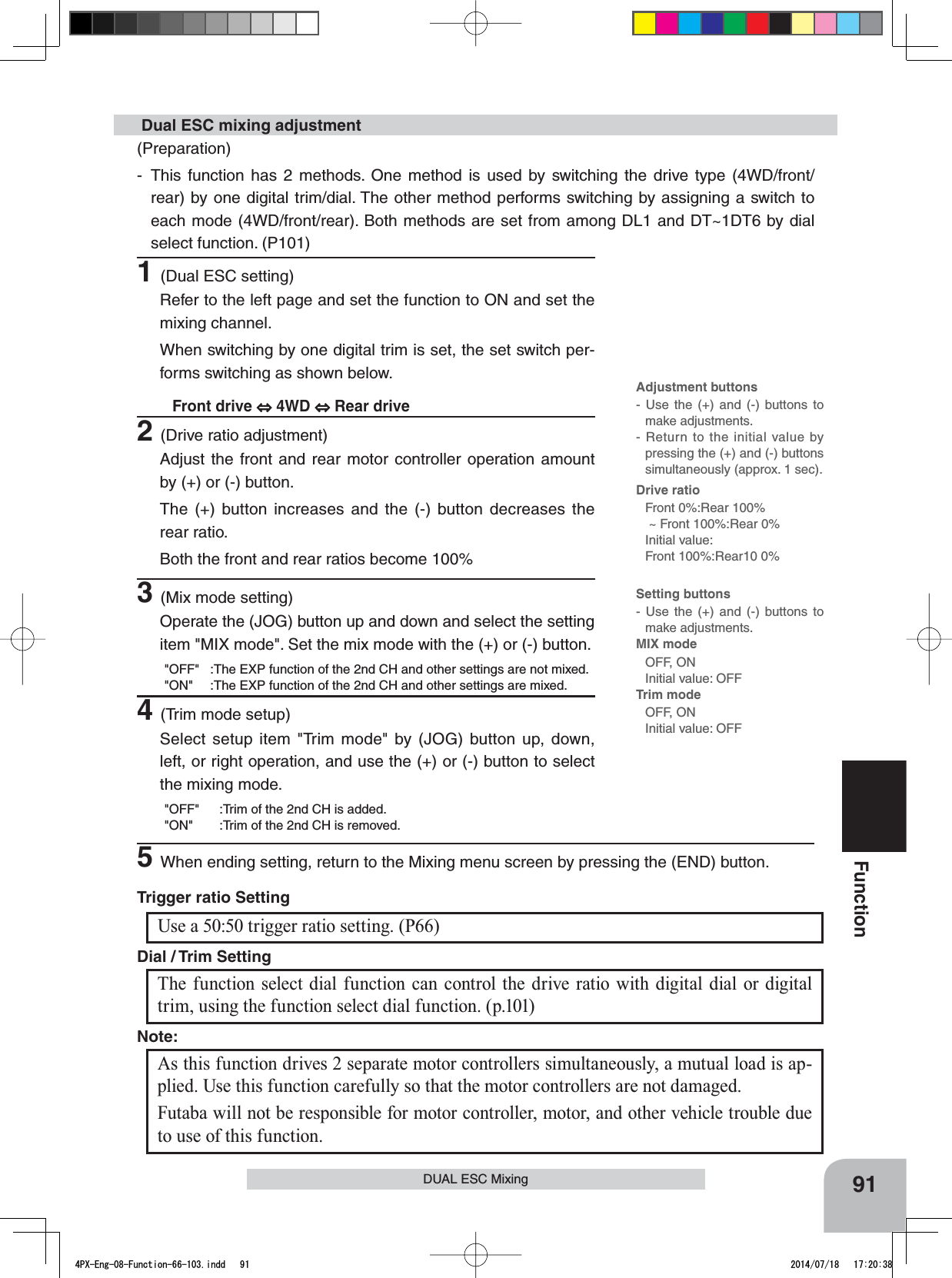
![105FunctionTimer FunctionLap timer functionLap timer function- The Lap timer can memorize each lap time of each switch operation. (60 laps)- The race time can be set. Switch operation after the set time by alarm has elapsed automatically stops the timer. Prealarm can also be set. The pas-sage of time is announced by sounding of a buzzer (beeps) each minute after starting. -Alarm :Generates a beep at the set time.Prealarm :Starts sounding the set time (second) be-fore the alarm. (beeps)7KH ¿UVWVWDUW RSHUDWLRQFDQ EH OLQNHGZLWKWKHthrottle trigger.(Lap timer operation)- When lap timer is selected, the number of laps (LAP) and the lap memory No. (No.) and current lap time (TIME) are displayed on the setup screen.*LAP: Counted up each time the switch is pressed after starting. After the switch was pressed, the numbers pause for 3 seconds. To prevent erroneous counting, switch operation is not accepted during this time*Lap memory: The lamp memory saves the lap times of 60 laps.*The lap time data stored in the lap memory can be checked at the lap list (P111) screen.Lap navigate timer functionLap navigate timer function7KLVIXQFWLRQVRXQGVDEX]]HUDWD¿[HGLQWHUYDOafter the timer starts. Since only the buzzer can be restarted when the switch is pressed during timer operation, this function can be used as the train-ing run, etc. target time. (Lap navigation alarm) The passage of time is announced by sounding of a buzzer (beeps) every minute after starting.7KH ¿UVWVWDUW RSHUDWLRQFDQ EH OLQNHGZLWKWKHthrottle trigger.- The alarm sounds (alarm/prealarm) can be set VHSDUDWHO\IURPWKH¿[HGLQWHUYDOEX]]HU- Alarm :Generates a beep at the set time (minutes).- Prealarm :Alarm advance announcement sound. Sounding begins 10 seconds before the set alarm time.- After starting, the timer is enabled and can be stopped by switch even when the display switches to another screen.4PX-Eng-08-Function-104-156.indd 105 2014/07/18 17:36:07](https://usermanual.wiki/Futaba/T4PX-24G.User-Manual-Part-2-Page-52-111/User-Guide-2346280-Page-54.png)