Contents
- 1. User Manual-Part 1 (Page 1-51)
- 2. User Manual-Part 2 (Page 52-111)
- 3. User Manual-Part 3 (Page 112-163)
User Manual-Part 2 (Page 52-111)
HOME
screen MENU 2
screen
or
MENU 1 screen
Pres
s
Pres
s
Pres
s
The rate of the current channel is
displayed in blue.
Pre
Pres
s
52
Function
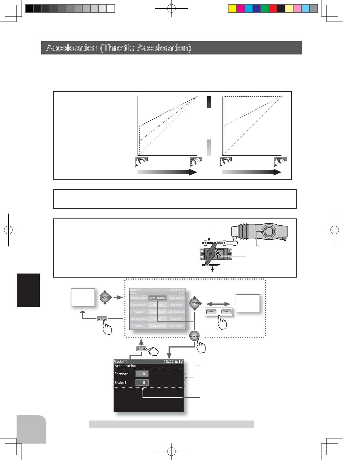
Acceleration (Throttle Acceleration)
Caburetor
Brake side
Servo horn
Clearance
FWRD
Servo travel
BRAKE
0%
50%
100%
0%
50%
100%
Setup item
Forward side
acceleration amount
Brake side
acceleration amount
- Operation near the throt-
tle trigger neutral position
becomes a sharp rise.
- The forward and brake
sides can be set separate-
ly.
- When the brake mixing
function (p.80) is set, the
CH3/CH4 brake can also
be set.
Operation
Acceleration (Throttle Acceleration) (Throttle system)
The servo will jump to the input position at its maximum possible speed. Unlike exponen-
tial, which adjusts the whole throttle movement into a curve, throttle acceleration simply
"jumps" away from neutral and then leaves the remaining response linear.
The standard value (100% point) of this setup affects the operation amount set by
throttle end point function.
Set value
For gasoline engine cars, the linkage must have a
clearance because one servo controls the engine
carburetor and brake. Thus, there is a noticeable
time delay at both the forward and brake sides.
Sharp response comparable to that of electric mo-
tor cars is obtained by reducing this clearance at
the transmitter side.
Convenient usage method
4PX-Eng-08-Function-46-65.indd 52 2014/07/18 17:14:51
Brake2 Brake3 Brake2 & 3
53
Function
Acceleration (Throttle Acceleration)
(Preparation)
- Select the setting item "Forward" by (JOG) button up or down
operation and make the following adjustments:
1(Forward acceleration amount adjustment)
Use the (+) and (-) buttons to adjust the acceleration amount.
"0" :No acceleration
"100" :
Maximum acceleration (Approximately 1/2 of the forward side throttle angle)
2(Brake side acceleration amount adjustment)
Select the setting item "Brake1" by (JOG) button up or down
operation and use the (+) and (-) buttons to adjust the accel-
eration amount.
"0" :No acceleration
"100" :Maximum acceleration (Brake side maximum throttle angle)
3
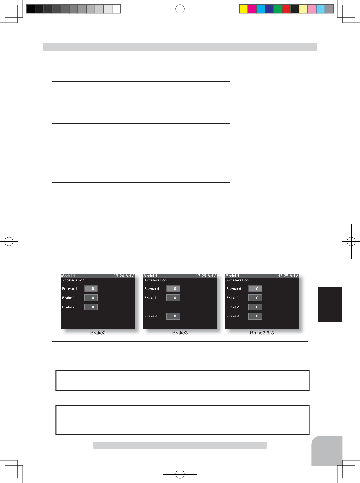
(3rd & 4th channel brake side acceleration amount adjustment)
If the "Brake Mixing Function" (p.80) is being set, the 3rd or 4th
channel brake side acceleration will become adjustable.
Select the setting item "Brake 2" or "Brake3" by (JOG) button
up or down operation and adjust acceleration amount by (+) or
(-) button.
"0" :No acceleration
"100" :Maximum acceleration (Brake side maximum throttle angle)
Throttle acceleration adjustment
The throttle acceleration adjustment amount (Forward), (Brake1), 3rd channel and 4th
channel (Brake2, Brake3) can be controlled with digital trim DT1-DT6 or digital dial
DL1 etc. with the function select dial function. (p.101)
Dial / Trim Setting
Adjustment buttons
Adjust with the (+) and (-) but-
tons.
- Return to the initial value "0" by
pressing the (+) and (-) buttons
simultaneously for about 1 sec-
ond.
Forward acceleration amount
(Forward)
0~100
Initial value: 0
Brake side acceleration amount
(Brake1)
0~100
Initial value: 0
3rd/4th channel
brake side
acceleration
amount
(Brake2),(Brake3)
0~100
Initial value: 0
When Trigger Ratio (p.66) was set to 100:0, brake operation is stopped and the throttle
(brake side) cannot be adjusted.
Caution
4When ending setting, return to the menu screen by pressing the (END) button.
4PX-Eng-08-Function-46-65.indd 53 2014/07/18 17:14:52
Receiver setting
FASST
Receiver setting
T-FHSS/S-FHSS
HOME
screen MENU 2
screen
or
MENU 1 screen
Pres
s
Pres
s
Pres
s
* When fail safe is set, that servo position is displayed.
Mode
Pre
Pres
s
54
Function
Fail Safe/Battery Fail Safe Function
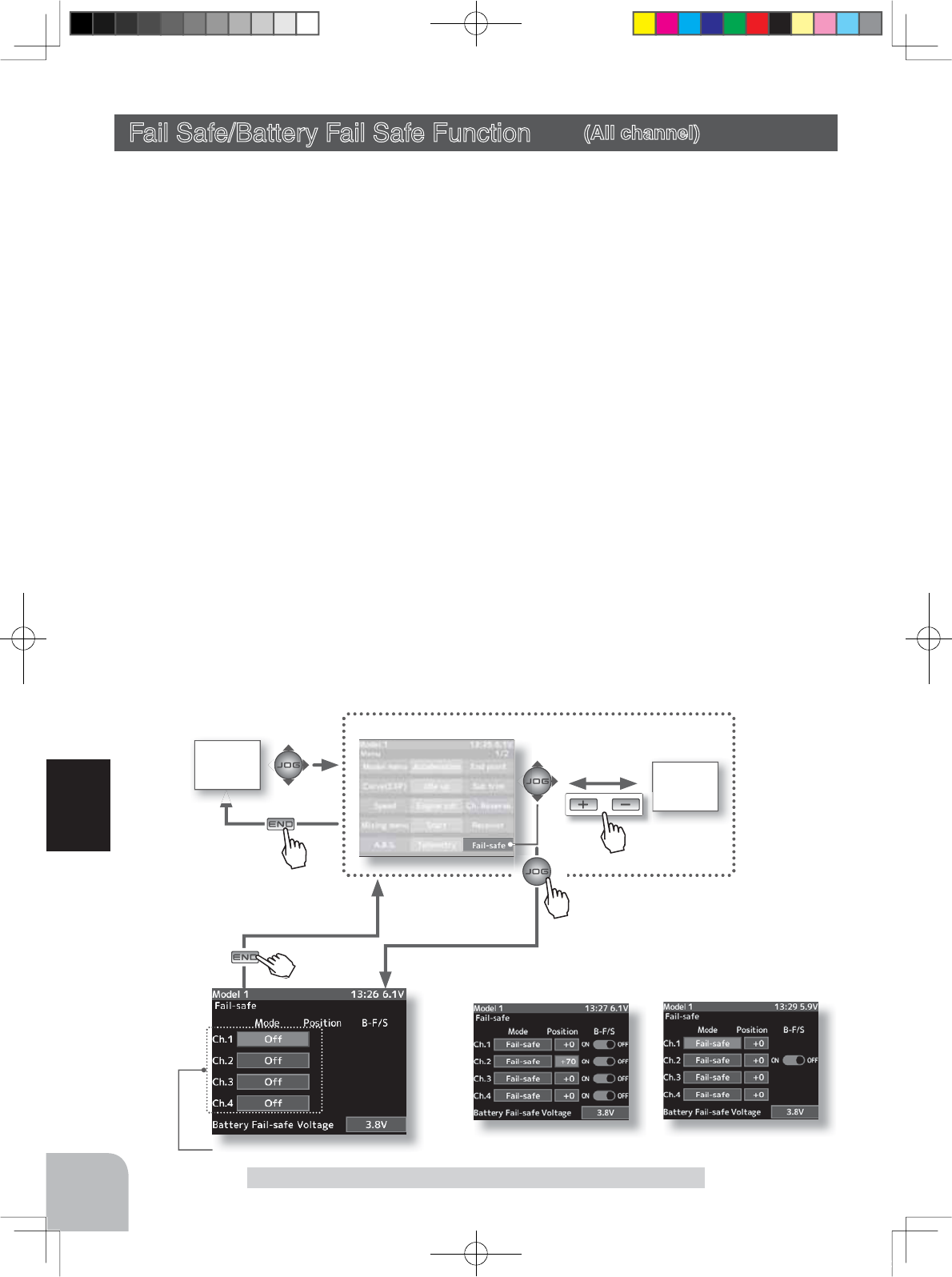
Fail Safe/Battery Fail Safe Function (All channel)
This function sets the servo operation position when transmitter signals cannot be received
by the receiver for some reason or the battery voltage has dropped.
-Fail safe mode
This function moves each servo to a preset position when the receiver cannot receive the
signals from the transmitter for some reason.
*The fail safe data is transferred from the transmitter to the receiver 10 seconds after the transmitter power was turned on.
The data is transferred every 10 seconds after that. Be careful because normally the trans-
PLWWHUSRZHULVWXUQHGRQ¿UVWDQGWKHUHFHLYHUSRZHULVWXUQHGRQQH[WDQGWKHUHLVQR
data transfer for about 10 seconds after the receiver power is turned on.
*For gasoline engine cars, for safety we recommend that this fail safe function be used to set the throttle channel in the di-
rection in which the brakes are applied.
-
Hold mode
This function holds the receiver in its position immediately before reception was lost.
-
Off mode (OFF)
This function stops output of signals to the servos and places the servos into the free state
when the receiver cannot receive.
The F/S, HOLD, and OFF modes are automatically reset when signals from the transmit-
ter can be received again
-
Battery fail safe function (B-F/S)
If the receiver battery voltage drops below a certain value when this function is enabled,
the throttle servo moves to the position set by fail safe function. When the battery voltage
ecovers, the battery fail safe function is automatically reset.
*This function cannot be used when the channel is not set to fail safe.
*When the receiver setting (P36) is "FASST", only CH2 (throttle) can use this function.
4PX-Eng-08-Function-46-65.indd 54 2014/07/18 17:14:52
Fail safe mode selection
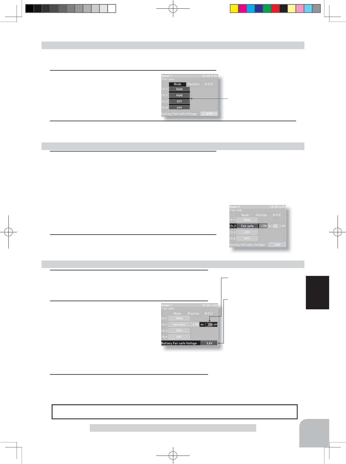
- Select with the (+) or (-) but-
tons.
Battery fail safe function
OFF, ON
Initial value: OFF
Setup item selection
- Select by (JOG) button up or
down operation.
Fail safe position setup button
- The (JOG) button are pressed
simultaneously for about 1 sec-
ond.
Fail safe mode
Off, Hold, Fail-safe
55
Function
Fail Safe/Battery Fail Safe Function
1(Battery fail safe function ON/OFF)
Select "OFF" or "ON" of "B-F/S" by (JOG) button opera-
tion. Set B-F/S function ON/OFF by (+) or (-) button.
2(Battery fail safe voltage setting)
Select battery fail safe **V at the bot-
tom of the screen by (JOG) button op-
eration. Set the voltage that turns on
the B-F/S function by (+) or (-) button.
(Since R604 Series receivers are not for high voltage use,
the use of LiFe and Li-Po batteries is prohibited. There-
fore, the 4.8v and 5.6v settings are prohibited.)
3When ending setting, return to the menu screen by press-
ing the (END) button.
Battery fail safe function ON/OFF & BATT-F/S voltage setting
BATT-F/S Voltage
T-FHSS
3.5,3.8,4.0,4.2,4.4,4.6,4.8,5.0,
5.3,5.6,5.9,6.2,6.5,6.8,7.1,7.4V
FASST
3.5,3.8,4.4,4.75
5.5V
(
Only R614
)
S-FHSS
Only 3.8V
Example:
Ni-MH /Ni-Cd 4cell---3.8V
Ni-MH /Ni-Cd 6cell---4.4V
LiFe 2cell---4.8V
Li-Po 2cell---5.6V
When the receiver power supply of an electric car uses a common power supply from an ESC, we recommend that this function be set
to OFF because the voltage supplied to the receiver may drop momentarily and the battery fail safe function may be activated.
(Preparation)
- Select the channel to be set by (JOG) button operation.
1(Mode selection)
Select the mode by (+) or (-) button.
(Each channel can be individually set.)
Fail safe mode selection
1(Servo position setup)
When the fail safe function operates, select the channel’s
"Position" to be set by (JOG) button operation.
The steering wheel, the throttle trigger or 3rd, 4th channels
dial remains in the desired operation position. When the (JOG)
button are pressed simultaneously for about 1 second, the
servo position is displayed and you can confirm that the func-
tion was set.
(Each channel can be set similarly.)
2When ending setting, return to the HOME screen by press-
ing the (END) button.
Fail safe function setup
2When ending hold or off mode setting, return to the HOME screen by pressing the (END)
button. When setting fail safe, set the servo position by the following method.
4PX-Eng-08-Function-46-65.indd 55 2014/07/18 17:14:52
or
MENU 1 screen
HOME
screen
MENU 2
screen
Pres
s
Pres
s
Pres
s
Pres
s
Pres
s
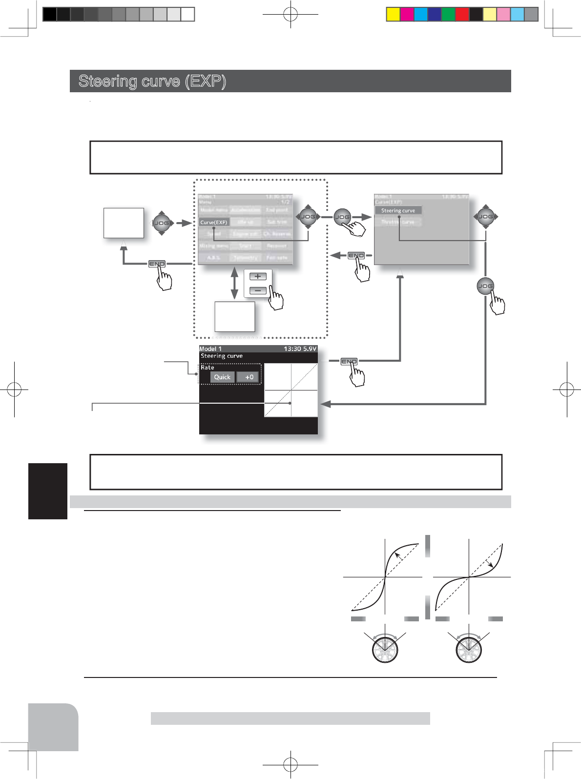
+1% ~ +100%
-1% ~ -100%
Wheel operation
Mild
(Negative side)
Quick
(Positive side)
Wheel operation
Servo travel
Vertical cursor moves in step
with steering wheel operation.
1When you want to quicken steering operation, use the (+)
button to adjust the + side. When you want to make steer-
ing operation milder, use the (-) button to adjust the - side.
Steering EXP adjustment
The steering EXP adjustment can be controlled with digital trim DT1~DT6 or digital
dial DL1 etc. with the function select dial function. (p.101)
Dial / Trim Setting
Adjustment buttons
Adjust with the (+) and (-) buttons.
- Return to the initial value "0" by pressing the (+) and (-)
buttons simultaneously for about 1 second.
Adjustment range
-100~0~+100%
Setup item
Rate: Steering EXP rate
When the setting item "Quick or mild" is selected and the
(JOG) button is pressed when the rate is other than "0",
quick/mild are reversed.
2When ending setting, return to the curve screen by pressing the (END) button.
56
Function
Steering curve (EXP)
Steering curve (EXP) (Steering system)
This function is used to change the sensitivity of the steering servo around the neutral posi-
tion. It has no effect on the maximum servo travel.
When the setting is not determined, or the characteristics of the model are unknown,
start with 0%. (When EXP is set to 0%, servo movement is linear.)
Racers Tip
Pre
Pres
s
4PX-Eng-08-Function-46-65.indd 56 2014/07/18 17:14:53
or
MENU 1 screen
HOME
screen
MENU 2
screen
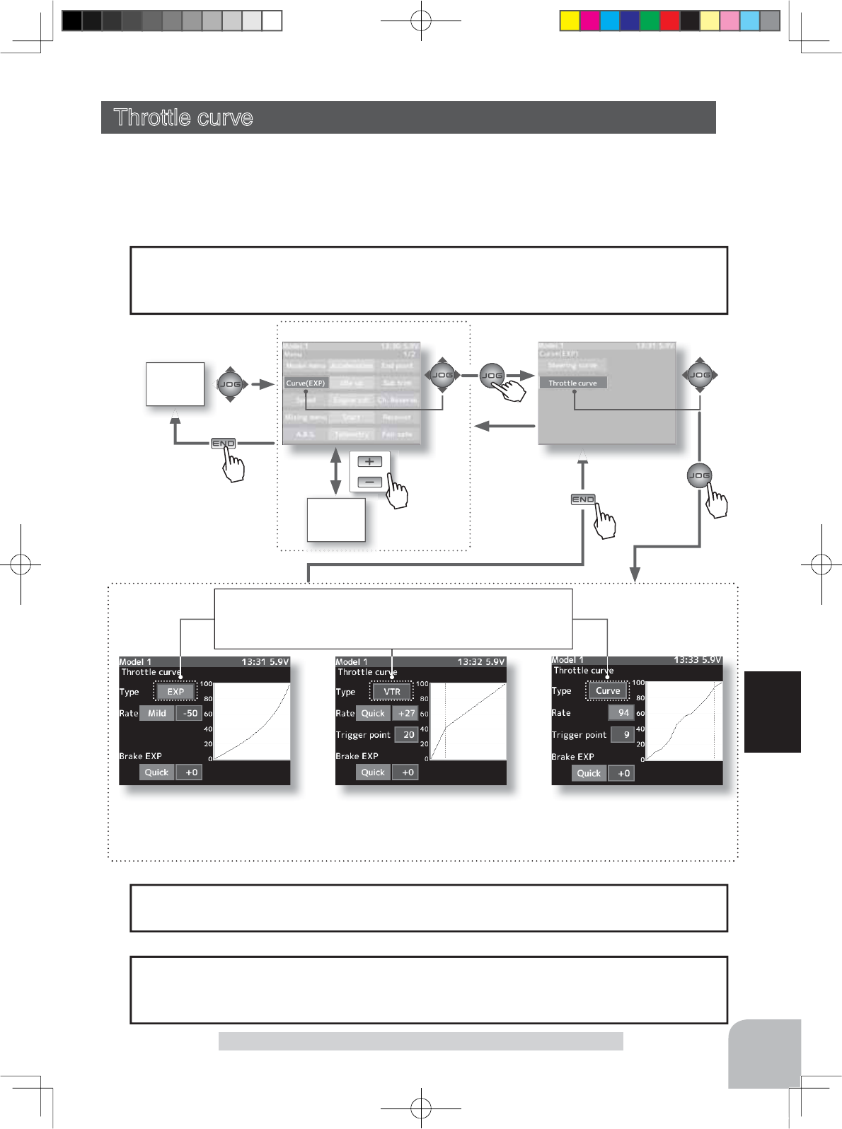
EXP curve screen
Curve type which operates the
throttle from the neutral point
to the high point on a curved
curve.
VTR curve screen
Curve type which sets the switching
point between the throttle neutral
point and high point and operates
the throttle on a linear curve.
CRV curve screen
Curve type which sets 9 points
between the throttle neutral point
and high point and operates the
throttle.
Pres
s
Pres
s
Pres
s
Pres
s
The throttle EXP curve and VTR curve adjustment (Foward side RATE) and(Brake side
RATE) can be controlled with digital trim DT1~DT6 or digital dial DL1 etc. with the
function select dial function. (p.101)
Dial / Trim Setting
When Trigger Ratio (p.66) was set to 100:0, brake operation is stopped and the throttle
(brake side) cannot be adjusted.
Caution
Curve selection
First, select the type of forward side curve at the "Type" item. The
setup item (screen) varies with the type of curve. The figure at the
above is the EXP curve setup screen.
Pre
Pres
s
57
Function
Throttle curve
Throttle curve (Throttle system)
This function makes the throttle high side and brake side direction servo operation
quicker or milder. It has no effect on the servo maximum operation amount.
For the high side, selection from among three kinds of curves (EXP/VTR/Curve) is also
possible.
When the course conditions are good and the surface has good grip, set each curve to the
+ side (quick side). When the road surface is slippery and the drive wheels do not grip it,
set each curve to the - minus (mild) side.
Advice
4PX-Eng-08-Function-46-65.indd 57 2014/07/18 17:14:54
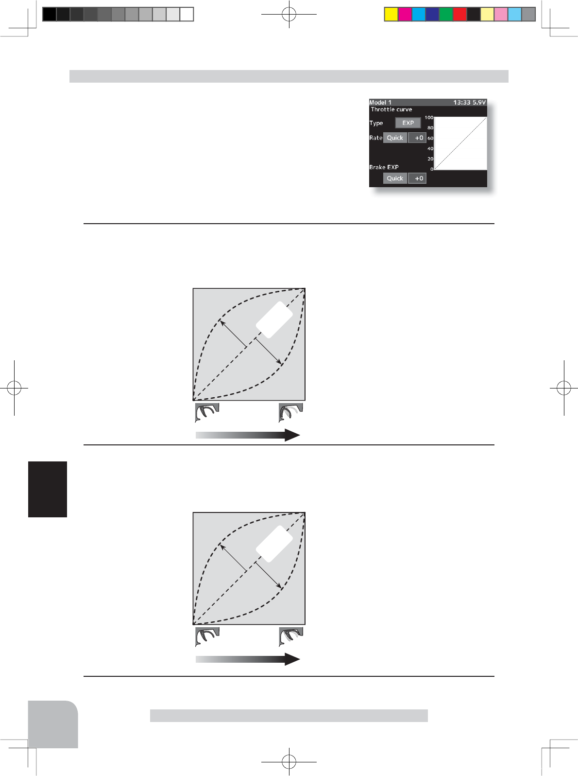
0%
Normal
+1% ~ +100%
Trigger operation
Quick
-1% ~ -100%
Mild
Servo travel
0%
Normal
+1% ~ +100%
Trigger operation
Quick
-1% ~ -100%
Mild
Servo travel
Adjustment range
Rate: -100 ~ 0 ~ +100%
Adjustment buttons
Adjust with the (+) and (-) buttons.
- Return to the initial value "0" by pressing the (+) and
(-) buttons simultaneously for about 1 second.
Adjustment range
Brake-EXP: -100 ~ 0 ~ +100%
Adjustment buttons
Adjust with the (+) and (-) buttons.
- Return to the initial value "0" by pressing the (+) and
(-) buttons simultaneously for about 1 second.
Quick/mild is reversed by (JOG) button, the same
as the forward side.
Setup items
Type :Forward side curve selection
Rate :Forward side rate
Brake-EXP :Brake side rate
Setup item selection
- Select by (JOG) button up or down operation.
Curve type Select button
- Select with the (+) or (-) buttons.
58
Function
Throttle curve
(Preparation)
- Select the "Type" to be set by (JOG) button operation.
With the plus (+) or minus (-) buttons, select "EXP".
Adjustment method for EXP curve
1Forward Exponential Adjustment
Select the "Rate" to be set by (JOG) button operation.
Use the plus (+) button to adjust for a faster throttle response or use the minus (-) button for
a slower or milder throttle response.
2
Brake Exponential Adjustment
Select the "Brake EXP" to be set by (JOG) button operation.
Use the plus (+) button to adjust for a faster brake response or use the minus (-) button for a
slower or milder brake response.
3
When ending setting, return to the curve screen by pressing the (END) button.
4PX-Eng-08-Function-46-65.indd 58 2014/07/18 17:14:54
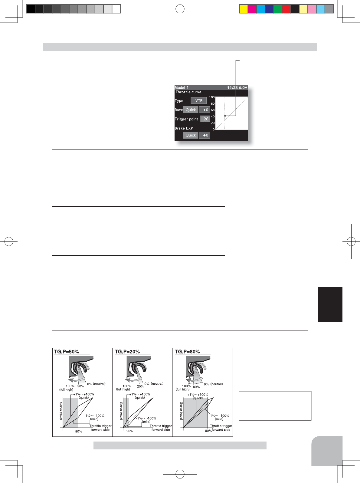
Setup items
Typ :Forward side curve selection
Rate :Forward side rate
Trigger point :Curve switching point
Brake-EXP :Brake side rate
Setup item selection
- Select by (JOG) button up or down operation.
Curve type Select button
- Select with the (+) or (-) buttons.
59
Function
Throttle curve
Switching point
A vertical cursor line that shows
the curve switching point is dis-
played on the setup screen graph.
(Preparation)
- Select the "Type" to be set by (JOG) button operation.
With the plus (+) or minus (-) buttons, select "VTR"
Adjustment method for VTR curve
Adjustment range
Rate :-100 ~ 0 ~ +100%
Trigger point :20 ~ 80%
Brake-EXP:-100 ~ 0 ~ +100%
For the VTR curve, only the
high side can be set. The
brake becomes the EXP
curve.
Adjustment buttons
Adjust with the (+) and (-) but-
tons.
- Return to the initial value by
pressing the (+) and (-) buttons
simultaneously (approx. 1 sec).
Initial value:
Rate and Brake-EXP "0"
Trigger point "50"
1
Forward side adjustment
Select the "Rate" to be set by (JOG) button operation. Use the plus (+) button to adjust for
a faster response. Use the minus (-) button for a slower or mild response. -Plus (+) button-
the higher the number goes on the positive side, the faster the response will be at center of
throttle response. -Minus (-) button- the higher the number goes on the negative side, the
milder or softer it is in the center of the throttle response.
2
Curve switching point adjustment
Select the "Trigger point" to be set by (JOG) button opera-
tion. Use the plus (+) or minus (-) buttons to move the point
you prefer. This gives you the opportunity of switching the
curve point in relation to the throttle trigger position.
3
Brake side adjustment
Select the "Brake EXP" to be set by (JOG) button operation.
Use the plus (+) button to adjust for a faster brake response
or use the minus (-) button for a slower or milder brake re-
sponse. When the setting item "Quick or mild" is selected
and the (JOG) button is pressed when the rate is other than
"0", quick/mild are reversed.
4
When ending setting, return to the curve screen by pressing the (END) button.
4PX-Eng-08-Function-46-65.indd 59 2014/07/18 17:14:55
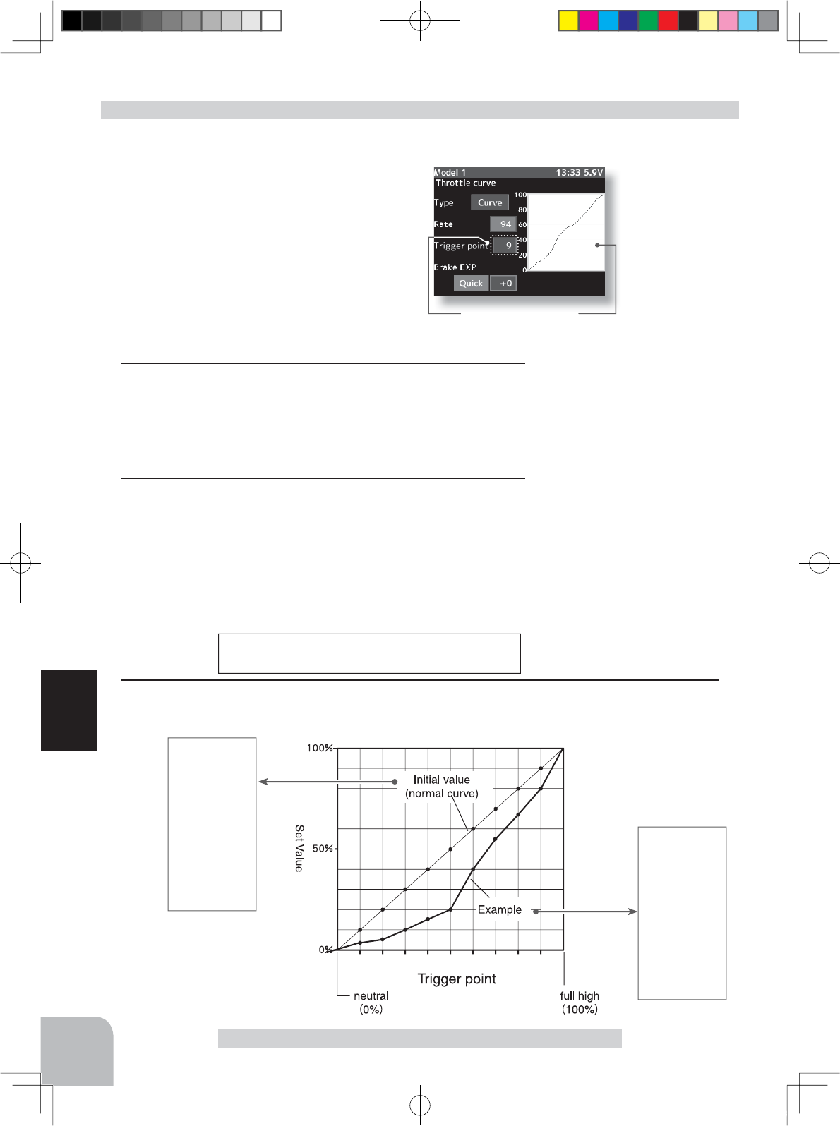
Throttle curve
Setup items
Type :Forward side curve selection
Rate :Forward side rate
Trigger point :Curve points 1~9
Brake-EXP :Brake side rate
Setup item selection
- Select by (JOG) button up or down operation.
Curve type Select button
- Select with the (+) or (-) buttons.
123456789
60
Function
Throttle curve
Initial value
P1 :10%
P2 :20%
P3 :30%
P4 :40%
P5 :50%
P6 :60%
P7 :70%
P8 :80%
P9 :90%
Example
P1 :3%
P2 :5%
P3 :10%
P4 :16%
P5 :20%
P6 :40%
P7 :55%
P8 :68%
P9 :80%
Current set point
The current set point and the trigger point are dis-
played by a vertical cursor on the graph.
(Preparation)
- Select the "Type" to be set by (JOG) button operation.
With the plus (+) or minus (-) buttons, se-
lect "Curve".
Adjustment method for VTR curve
Adjustment range
1: ~ 9 : 0 ~ 100%
Trigger point :1~9
Breke-EXP -100 ~ 0 ~ +100%
Adjustment buttons
Adjust with the (+) and (-) but-
tons.
- Return to the initial value by
pressing the (+) and (-) buttons
simultaneously (approx. 1 sec).
Initial value:
Point.1:10, 2:20, 3:30, 4:40,
5:50, 6:60, 7:70, 8:80, 9:90
Brake-EXP "0"
For the CRV curve, only the forward side can be set. The
brake becomes the EXP curve.
1Curve setup
- Select the setting item "1:" (1st point), by (JOG) button up,
down, left, or right operation, and use the (+) and (-) buttons
to set the 1st point. Set the throttle curve by sequentially set-
ting "2:" (2nd point) ~ "5:" (5th point).
2Brake side adjustment
Select the setting item "Brake EXP" by (JOG) button up or
down operation. When you want to quicken the rise, use the
(+) button to adjust the + side and when you want to make
the rise milder, use the (-) button to adjust the - side.
When
the setting item "Quick or mild" is selected and the (JOG) but-
ton is pressed when the rate is other than "0", quick/mild are
reversed.
3
When ending setting, return to the curve screen by pressing the (END) button.
4PX-Eng-08-Function-46-65.indd 60 2014/07/18 17:14:56
or
MENU 1 screen
HOME
screen
MENU 2
screen
Pres
s
Pres
s
Pres
s
Pres
s
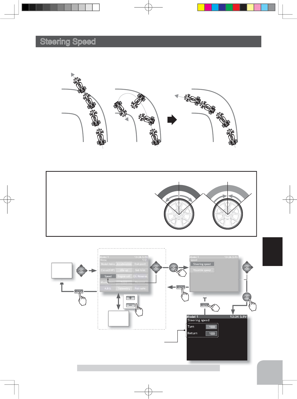
Without "Steering speed" With "Steering speed"
Understeering Smooth corneringSpin
Setup item
Turn direction
Return direction
Pre
Pres
s
Pre
Pres
s
61
Function
Steering Speed
Steering Speed (Steering system)
Quick steering operation will cause momentary understeering, loss of speed, or spin-
ning. This function is effective in such cases.
T
u
r
n
T
u
r
n
R
e
t
u
r
n
R
e
t
u
r
n
- This function limits the maximum speed of the steering servo. (Delay function)
- The steering speed when the steering
wheel is operated (Turn direction) and
returned (Return direction) can be inde-
pendently set.
- If the steering wheel is turned slower
than the set speed, the steering servo is
not affected.
Operation
4PX-Eng-08-Function-46-65.indd 61 2014/07/18 17:14:57
T
u
r
n
T
u
r
n
R
e
t
u
r
n
R
e
t
u
r
n
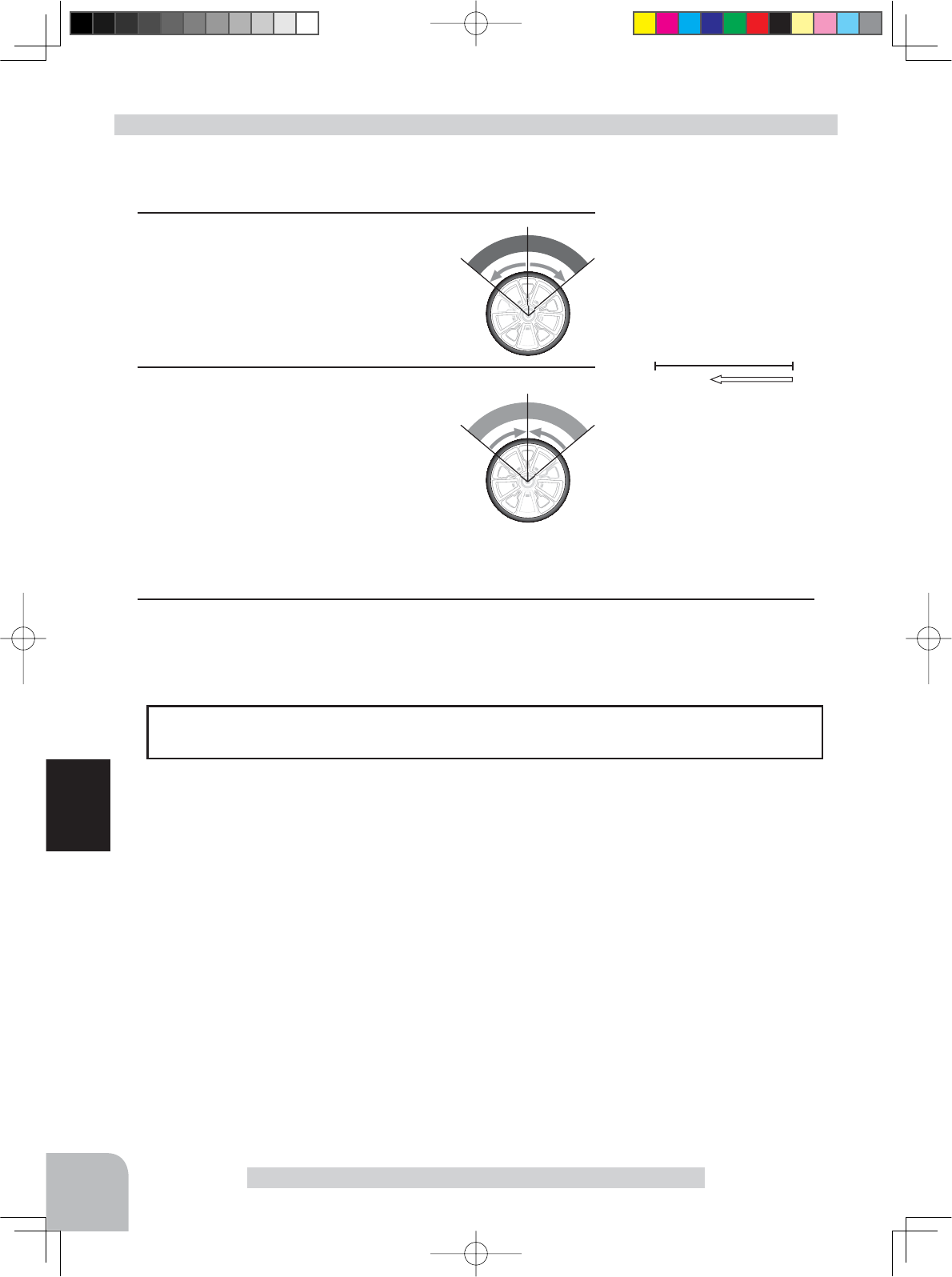
100%1%
Servo operation is delayed.
Adjustment buttons
- Adjust with the (+) and (-) but-
tons.
- Return to the initial value "0" by
pressing the (+) and (-) buttons
simultaneously for about 1 sec-
ond.
Adjustment range
1~100% (each direction)
At 100%, there is no delay.
Setup item selection
- Select by (JOG) button up or
down operation.
The steering speed adjustment
"
Tu r n
"
and
"
Return
"
can be controlled with digital trim
DT1-DT6 or digital dial DL1 etc. with the function select dial function. (p.101)
Dial / Trim Setting
62
Function
Steering Speed
(Preparation)
- Select the setting item "Turn" by (JOG) button up or down op-
eration, and make the following adjustments:
1"Turn" direction adjustment
Use the (+) or (-) buttons to adjust the
delay amount.
Steering Speed adjustment
2"Return" direction adjustment
Select the setting item "Return" by
(JOG) button up or down operation,
and use the (+) or (-) buttons to adjust
the delay amount.
3When ending setting, return to the speed screen by pressing the (END) button.
4PX-Eng-08-Function-46-65.indd 62 2014/07/18 17:14:57
or
MENU 1 screen
HOME
screen
MENU 2
screen
Pres
s
Pres
s
Pres
s
Pres
s
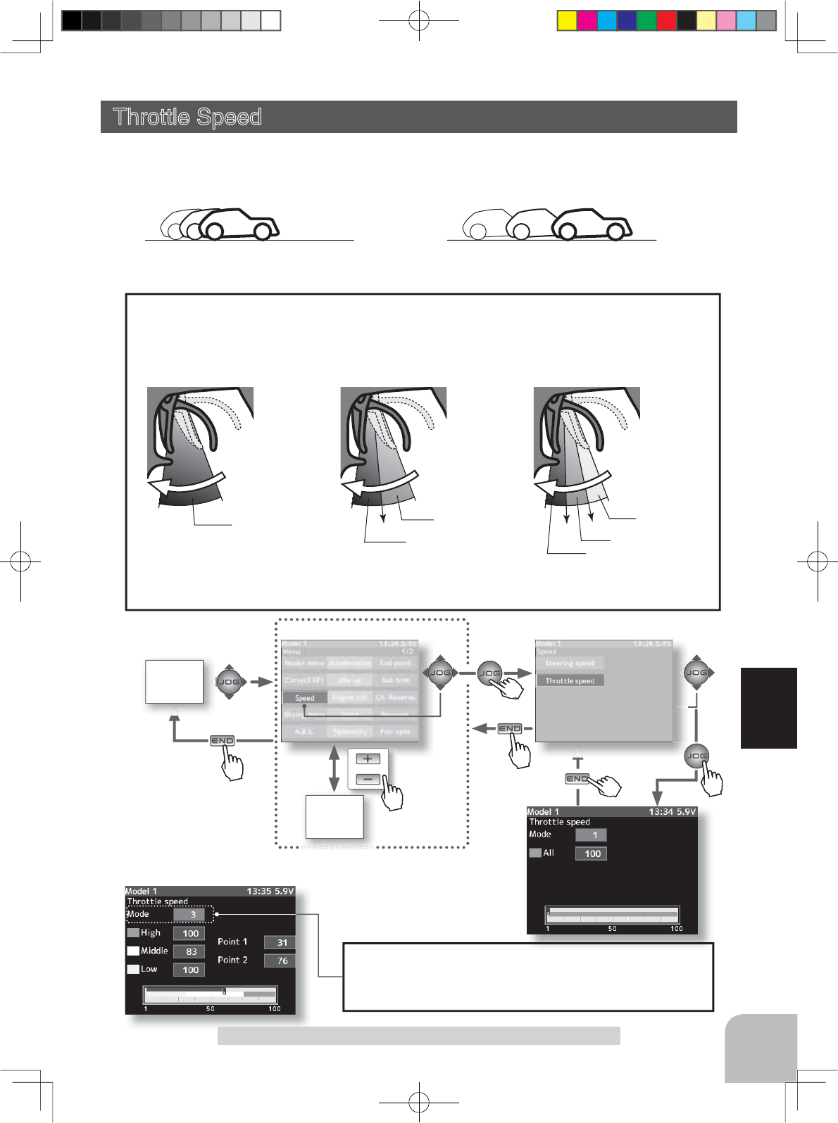
1 SPEED
A delay is set over the entire
throttle range.
2 SPEED
A delay can be set in 2 ranges
with Point1 as the boundary.
3 SPEED
A delay can be set in 3 ranges with
Point1 and Point2 as the boundaries.
Point1
high
neutral
high
neutral
high
neutral
Point2
Point1
ALL Low
High
Low
High
Middle
-Throttle servo (ESC) operation is delayed so that the drive wheels will not spin even if
the trottle trigger is operated more than necessary. This delay function is not performed
when the throttle trigger is returned and at brake operation.
-1 speed, 2 speed, or 3 speed can be selected.
Operation
Mode selection
One speed, 2 speed, or 3 speed can be selected at the "Mode"
item. The setting item (screen) depends on the mode. The figure at
the above is the 3 speed setup screen.
Pre
Pres
s
Pre
Pres
s
63
Function
With "Throttle speed":
Quick start without skidding
Without "Throttle speed":
Slow start due to skidding
Throttle Speed
Throttle Speed (Throttle system)
Sudden throttle trigger operation on a slippery road only causes the wheels to spin and the
vehicle cannot accelerate smoothly. Setting the throttle speed function reduces wasteful bat-
tery consumption while at the same time permitting smooth, enjoyable operation.
4PX-Eng-08-Function-46-65.indd 63 2014/07/18 17:14:58
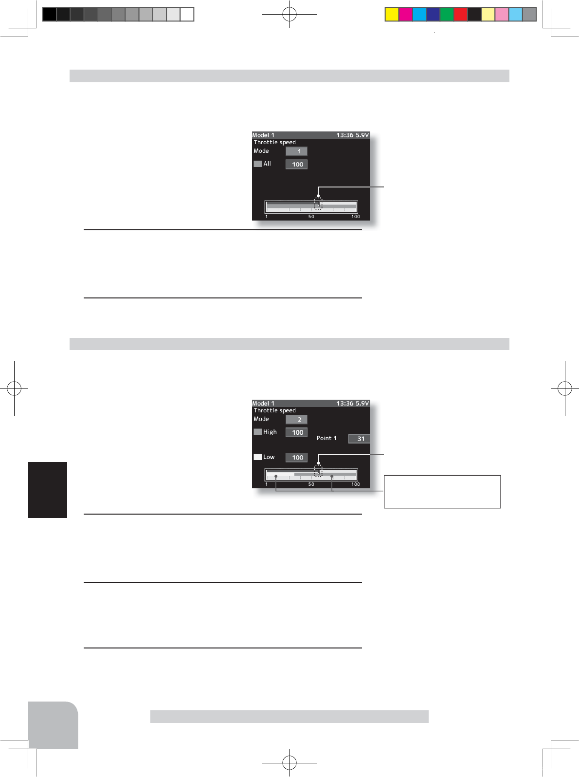
Setting item
Mode :Speed type selection
All :Speed adjustment
Setup item selection
- Select by (JOG) button up or down
operation.
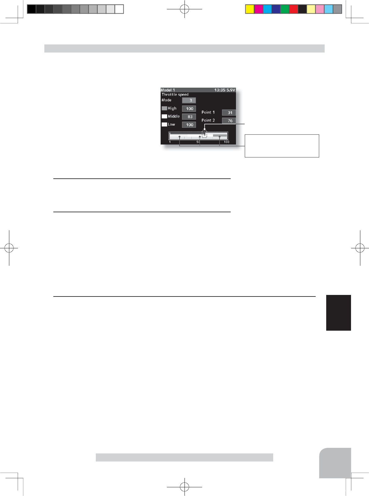
Setting item
Mode :Speed type selection
High :High side range speed
adjustment
Low :Low side range speed
adjustment
Point1 :Low and medium speed
switching point
Setup item selection
- Select by (JOG) button up or down
operation.
Throttle trigger position
Throttle trigger position
The Low and High ranges are
linked to the Point1 set point
and displayed.
Adjustment range
High :1~100
Low :1~100
At 100%, there is no delay.
Point1 :1~100
Adjustment buttons
- Adjust with the (+) and (-) but-
tons.
- Return to the initial value by
pressing the (+) and (-) buttons
simultaneously (approx. 1 sec).
Initial value
Low, High :"100"
Point1 :30
Speed type Select button
- Select with the (+) or (-) but-
tons.
Adjustment buttons
- Adjust with the (+) and (-) but-
tons.
- Return to the initial value "100"
by pressing the (+) and (-) but-
tons simultaneously for about 1
second.
Adjustment range
1~100% (each direction)
At 100%, there is no delay.
Speed type Select button
- Select with the (+) or (-) but-
tons.
64
Function
Throttle Speed
(Preparation)
- Select the setting item "Mode" by (JOG) button up or down op-
eration. Press the (+) or (-) button and select "1".
Adjustment method for 1 Speed
(Preparation)
- Select the setting item "Mode" by (JOG) button up or down op-
eration. Press the (+) or (-) button and select "2".
Adjustment method for 2 Speed
1("Low" and "High" delay adjustment)
Select "Low" or High" by (JOG) button up or down operation.
Use the (+) or (-) button to adjust the delay of the entire
throttle forward side range.
2(Speed switching point adjustment)
When you want to change the "Low" and "High" switching
point, select the setting "Point1" by (JOG) button up or down
operation.
3When ending setting, return to the speed screen by pressing
the (END) button.
1 ("ALL" delay adjustment)
Select "All" by (JOG) button up or down operation.
Use the (+) or (-) button to adjust the delay of the entire
throttle forward side range.
2When ending setting, return to the speed screen by pressing
the (END) button.
4PX-Eng-08-Function-46-65.indd 64 2014/07/18 17:14:58
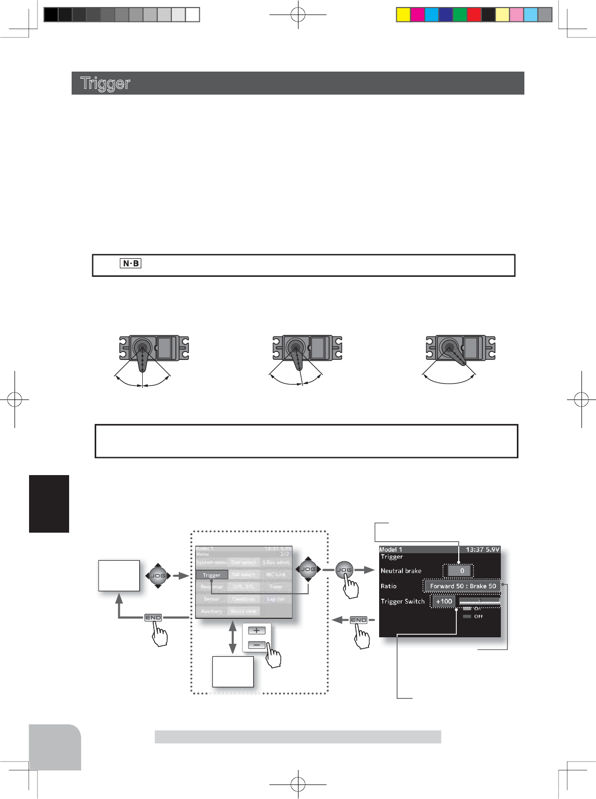
Setting item
Mode :Speed type selection
High :High side range speed
adjustment
Middle :Medium speed range
speed adjustment
Low :Low side range speed
adjustment
Point1 :Low and medium speed
switching point
Setup item selection
- Select by (JOG) button up or down operation.
Adjustment buttons
- Adjust with the (+) and (-) but-
tons.
- Return to the initial value by
pressing the (+) and (-) buttons
simultaneously (approx. 1 sec).
Initial value
Low, Middle, High:"100"
Point1 :30
Point2 :60
Speed type Select button
- Select with the (+) or (-) but-
tons.
The Low and High ranges are
linked with the Point1,2 set
points and displayed.
Throttle trigger position
Adjustment range
High :1~100
Middle :1~100
Low :1~100
At 100%, there is no delay.
Point1 :1~100
Point2 :1~100
65
Function
Throttle Speed
Adjustment method for 3 Speed
(Preparation)
- Select the setting item "Mode" by (JOG) button up or down op-
eration. Press the (+) or (-) button and select "3".
1("Low", "Middle", and "High" delay adjustment)
Select the setting item "Low", "Middle", or "High" by (JOG)
button up or down operation.
2(Speed switching point adjustment)
When you want to change the "Low", "Middle", and "High"
switching point, select setting item "Point1" or "Point2" by
(JOG) button up or down operation.
3When ending setting, return to the speed screen by pressing the (END) button.
4PX-Eng-08-Function-46-65.indd 65 2014/07/18 17:14:59
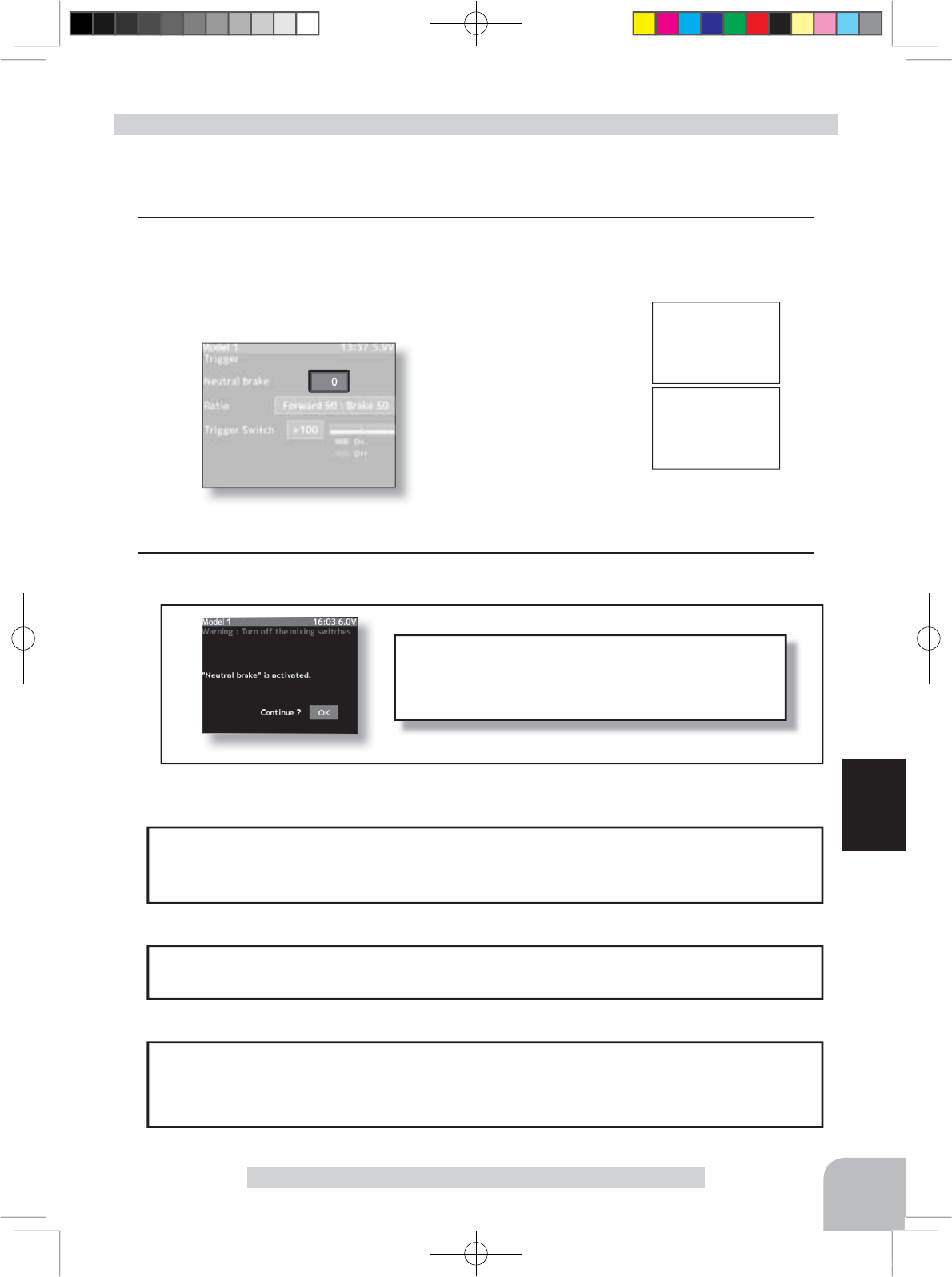
HOME
screen
or
MENU 2 screen
MENU 1
screen
Neutral Brake
0~100 Initial value: 0
Pres
s
Pres
s
Pres
s
Pres
s
Trigger ratio
Forward50:Brake50
Forward70:Brake30
Forward100:Brake0
Trigger switch point
-100~+100
Initial value: +100
66
Function
Forward 50:Brake 50 Forward 70:Brake 30 Forward 100:Brake 0
Forward sideForward side Forward sideBrake sideBrake side Brake side
5:5 7:3 10 : 0
When the trigger ratio was set to 100:0, brake operation stops and the neutral brake can-
not be used.
When trigger ratio was set to 100:0
-The trigger switch function operates the trigger as a switch.
The trigger point can be selected and mixing, engine cut, and other functions can be turned
on and off.
The display appears on the home screen.
Operation display
Trigger
-The neutral brake function is a function switch function (p.99), and setting the neutral
brake function ON/OFF switch is necessary.
Neutral brake, which applies the brakes at the throttle trigger neutral position, can be set.
However, for Futaba speed controller (ESC) MC960CR, MC950CR, MC851C, MC602C,
0&&5HWFFRQVLGHULQJVDIHW\ZKHQWKHQHXWUDOSRVLWLRQLVQRWFRQ¿UPHGWKHVHWZLOO
not enter the operation mode to prevent the motor from rotating instantly when the power
is turned on. When using the MC960CR, MC950CR, MC851C, MC602C, MC402CR, etc.,
check that the ESC is in the neutral position and set the neutral brake function switch to ON
after the set enters the operation mode.
Trigger (Throttle system)
-This function allows selection of the forward side and brake (reverse) side operation ratio
from 70:30, 50:50 or 100:0 by changing the neutral position of the throttle servo.
4PX-Eng-08-Function-66-103.indd 66 2014/07/18 17:20:28
Warning display
If the power switch is turned on while the neutral
brake switch is on, an audible alarm will be heard.
Immediately set the neutral brake switch to OFF.
67
Function
Trigger
Neutral brake
On
Neutral brake
O
ff
Neutral brake ON/OFF is dis-
played by pop-up window in
the home screen.
(Preparation)
- Use the function select switch function to select the switch. (p.99)
1(Neutral brake rate)
Select the setting item "Neutral brake" by (JOG) button up or down operation. Use the (+)
and (-) buttons to set the neutral brake rate.
Neutral Brake function adjustment
2When ending setting, return to the menu screen by pressing the (END) button.
Adjust button
- Adjust with the (+) and (-) buttons.
- Return to the initial value "100" by
pressing the (+) and (-) buttons
simultaneously for about 1 sec-
ond.
Neutral Brake
0~100
Initial value: 0
The ESC neutral brake function and T4PX neutral brake function can be used simulta-
QHRXVO\+RZHYHUZKHQVHWWLQJLVGLI¿FXOWWRXQGHUVWDQGZHUHFRPPHQGWKDWRQO\RQH
neutral brake function be used.
Reference
When the neutral brake function is
"
ON
"
, the
neutral
brake rate adjustment is automati-
cally assigned to the throttle trim (DT1~DT6 or DL1).
Dial / Trim Setting
Throttle side EPA function, or ATL function setting also affects neutral brake side op-
eration.
The Idle-up (p.69) or Engine Cut (p.71) function has priority.
Effect of set value of other functions on neutral brake
4PX-Eng-08-Function-66-103.indd 67 2014/07/18 17:20:28
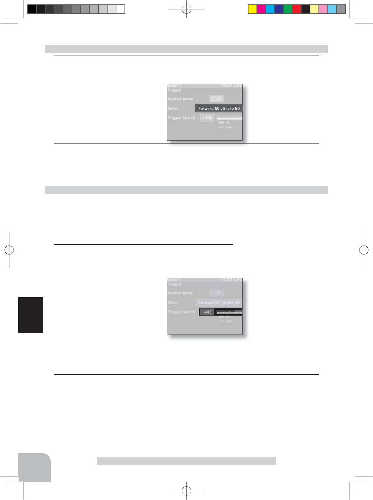
Forward50:Brake50
Forward70:Brake30
Forward100:Brake0
Trigger switch point
-100~+100
Initial value: +100
Setting buttons
- Use the (+) and (-) buttons to
make adjustments.
Adjustment buttons
- Use the (+) and (-) buttons to
make adjustments.
68
Function
(Preparation)
-This function is the switch select function (p.99) and sets the functions used at switch TS.
-The standard is trigger high direction ON. When set to ON by brake direction, the direction is
set to reverse at the switch setup screen.
Trigger switch setting method
Trigger
1 (Trigger switch ON/OFF point setting)
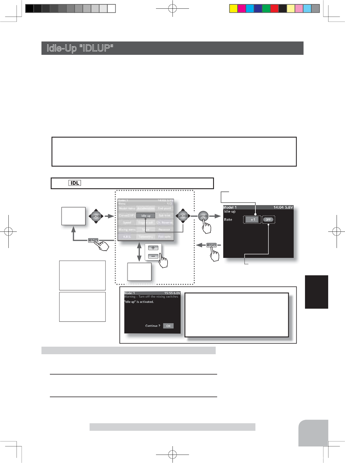
Select the setting item trigger switch by (JOG) button up or
down operation.
Set the ON/OFF switching point by
(+) and (-) button.
The ON/OFF switching point can
also be set by holding the trigger
in the position to be set as the ON/
OFF switching point and pressing
the (JOG) button. Fine adjustment
is possible by (+) and (-) button.
The red part of the bar graph is the ON direction.
2When ending setting, return to the menu screen by pressing the (END) button.
1 (Throttle mode selection)
Select the setting item "Ratio" by (JOG) button up or down operation.
Select "Forward 50:Brake 50",
"Forward 70:Brake 30" or "For-
ward 100:Brake 0" by (+) or (-)
button.
Selecting the trigger ratio
2When ending setting, return to the menu screen by pressing the (END) button.
4PX-Eng-08-Function-66-103.indd 68 2014/07/18 17:20:28
HOME
screen
or
MENU 2
screen
MENU 1 screen
Pres
s
Pres
s
Pres
s
Pu h
Pres
s
If the power switch is turned on
while the idle-up switch is on, an
audible alarm will be heard. Im-
mediately set the Idle-Up switch to
OFF.
69
Function
Idle-Up
Idle up
On
Idle up
O
ff
Idle up ON/OFF is displayed
by pop-up window in the home
screen. Warning display
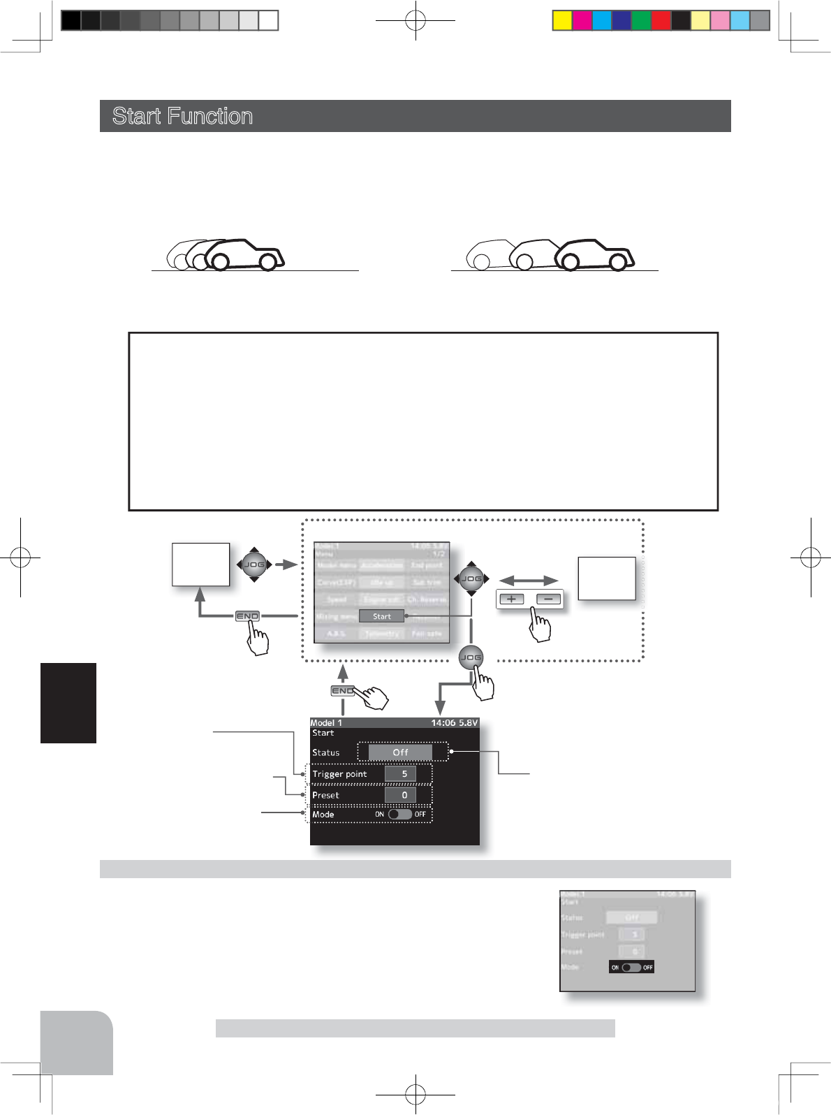
This is a function select switch function. The idle-up function switch must be set. (p.99)
It is used to improve engine starting performance by raising the idling speed when the en-
gine of a gasoline car (boat) is started.
This function is also effective when you want to prevent braking when the power was
turned off during running due to the effect of gear ratio setting and the motor used with
a motor car. However, when using the MC960CR, MC950CR, MC851C, MC602C, MC-
402CR, etc., check the ESC neutral position and set the idling function switch to ON after
the set enters the operation mode, the same as the neutral brake function (p.66).
The throttle neutral position is offset to the forward side or brake side. There is no link-
age locking, etc. because there is no change near the maximum operation angle even
when the neutral position is offset by this function.
Operation
Idle-Up on/off state.
(Preparation)
- Use the function select switch function to select the switch. (p.99)
1(Idle-Up rate)
Use the (+) and (-) buttons to set the Idle-Up rate.
2When ending setting, return to the menu screen by pressing
the (END) button.
Idle-Up function adjustment
Idle-Up "IDLUP" (Throttle system)
Adjust button
- Adjust with the (+) and (-) but-
tons.
- Return to the initial value "0" by
pressing the (+) and (-) buttons
simultaneously for about 1 sec-
ond.
Idle-Up Rate
-
50 ~ 0 ~ +50
Idle-Up rate
-
50 ~ 0 ~ +50
"-": Brake side
"+": Forward side
Initial value: 0%
The display appears on the home screen.
Operation Display
4PX-Eng-08-Function-66-103.indd 69 2014/07/18 17:20:29
HOME
screen MENU 2
screen
or
MENU 1 screen
Trigger point
5~95
Mode (Start function)
ON/OFF
Preset (Servo position )
0~100%
Pres
s
Pres
s
Pres
s
Pu
h
Pres
s
70
Function
Start Function
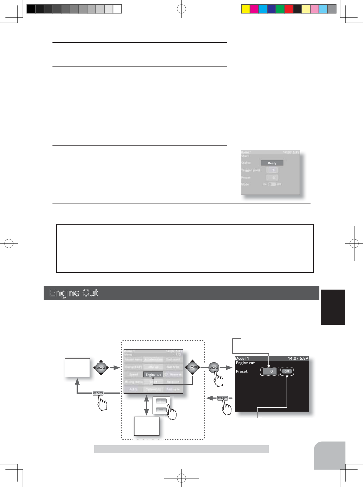
Start Function Operation
- When the throttle trigger is moved to the preset position (trigger point), the throttle
servo moves to the preset position.
- When the throttle trigger is operated slowly so that the wheels will not spin, the car au-
tomatically accelerates to the set speed.
7KLV IXQFWLRQLVHIIHFWLYHRQO\IRUWKH¿UVWWKURWWOHWULJJHU RSHUDWLRQ DW VWDUWLQJ 7KLV
function has to be activated before every start.
- When the throttle trigger is returned slightly, the Start function is automatically deacti-
vated and the set returns to normal throttle trigger operation.
Start Function (Throttle system)
If the track is slippery and you begin to accelerate by pushing the trigger to full throttle,
the car wheels will spin and the car will not accelerate smoothly. When the Start function is
activated, merely operating the throttle trigger slowly causes the throttle servo to automati-
cally switch from the set throttle position to a preset point so that the tires do not lose their
grip and the car accelerates smoothly.
With "Start function":
Quick start without skidding
Without "Start function":
Slow start due to skidding
(Preparation)
- Select the setting item "Mode" by (JOG) button up or down op-
eration. Press the (+) or (-) button and select "ON".
- Select setup item "Trigger point" and make the following ad-
justments.
Start function adjustment
Status
Off
Ready
Active
4PX-Eng-08-Function-66-103.indd 70 2014/07/18 17:20:30
HOME
screen
or
MENU 2
screen
MENU 1 screen
Pres
s
Pres
s
Pres
s
Pres
s
71
Function
Start Function/ Engine Cut
Engine Cut (Throttle system)
When the switch is pressed, the throttle servo will move to the preset position without re-
gard to the throttle trigger position. This is convenient when used to cut the engine of boats,
etc. (The function select switch function. See page 99)
-If the throttle trigger is moved to the set position while "Ready" on the screen, the throt-
tle servo will move to the set position. The throttle operation wait state is reset when the
throttle trigger is returned.
-When using the Start function, always set the function by performing step 3 above each
time.
Adjust button
- Adjust with the (+) and (-) but-
tons.
- Return to the initial value by
pressing the (+) and (-) buttons
simultaneously (approx. 1 sec).
Setup item selection
- Select by (JOG) button up or
down operation.
Preset position
0, F1 ~ F100
Initial value: 0
Trigger point
5 ~ 95
Initial value: 5
1(Throttle position setup)
Set the throttle position by pressing the (+) or (-) button.
2(Preset position setup)
Select the setting item "Preset" by (JOG) button up or down
operation, and use the (+) and (-) buttons to set the preset
position of the throttlle servo.
"0" :Neutral
"F0" ~ "F100":Forward side
Setting Example: (When ESC used with an electric car)
Set the preset position to F75% at EPA100%.
3("Ready" setting)
Select the setting item "Status" by (JOG) button up or down
operation, and press the (JOG) buttons simultaneously for
about 1 second. "Ready" on the screen and the system en-
ters the "Ready" state. Throttle trigger operation starts the
function.
4When ending setting, return to the menu screen by pressing the (END) button
Engine cut on/off state.
Preset Rate
0 ~ 100
4PX-Eng-08-Function-66-103.indd 71 2014/07/18 17:20:30
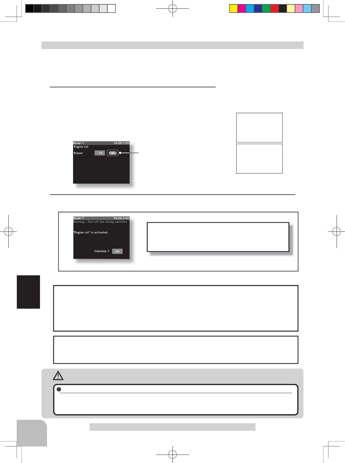
Engine cut
On
Engine cut
O
ff
If the power switch is turned on while the preset
(engine cut) switch is on, an audible alarm will be
heard. Immediately set the preset switch to OFF.
72
Function
When the trigger ratio (p.66) was set to 100:0, the brake function does not operate. The
preset position set here becomes the linkage standard. The linkage is set so that the car-
buretor is fully closed and the engine is stopped within the preset adjustment range. The
full throttle position is set by "Forward" of the end point function. The idling position is
adjusted by throttle trim.
When trigger ratio was set to 100:0
Engine Cut
When engine cut is active,
ON is displayed.
(Preparation)
- This is a function select switch function. The engine cut func-
tion switch must be set. (p.99)
- The engine cut is turned on with the set switch.
1(Preset position setup)
Use the (+) and (-) buttons to set the preset position of the
throttlle servo.
"B100" ~ "B1" :Brake side
"0" :Neutral
"F1" ~ "F100" :Forward side
Engine Cut function adjustment
2When ending setting, return to the menu screen by pressing the (END) button.
Warning display
The throttle servo operating position (preset position) set by this setting is unrelated to
the setting of other functions. Maximum to minimum servo travel can be set. However,
the reverse function setting is enabled.
Caution
Always operate carefully before using this function.
While push switch PS1~PS5, or trigger switch TS with preset function set is in the ON state, the servo (motor controller) is
locked in the preset position and does not operate even if the throttle trigger is operated. If the servo was operated at the
wrong setting, you may lose control of the car (boat).
Adjust button
- Adjust with the (+) and (-) but-
tons.
- Return to the initial value "0" by
pressing the (+) and (-) buttons
simultaneously for about 1 sec-
ond.
Preset rate
0 ~ 100
Initial value: 0%
Engine cut up ON/OFF is dis-
played by pop-up window in
the home screen.
4PX-Eng-08-Function-66-103.indd 72 2014/07/18 17:20:30
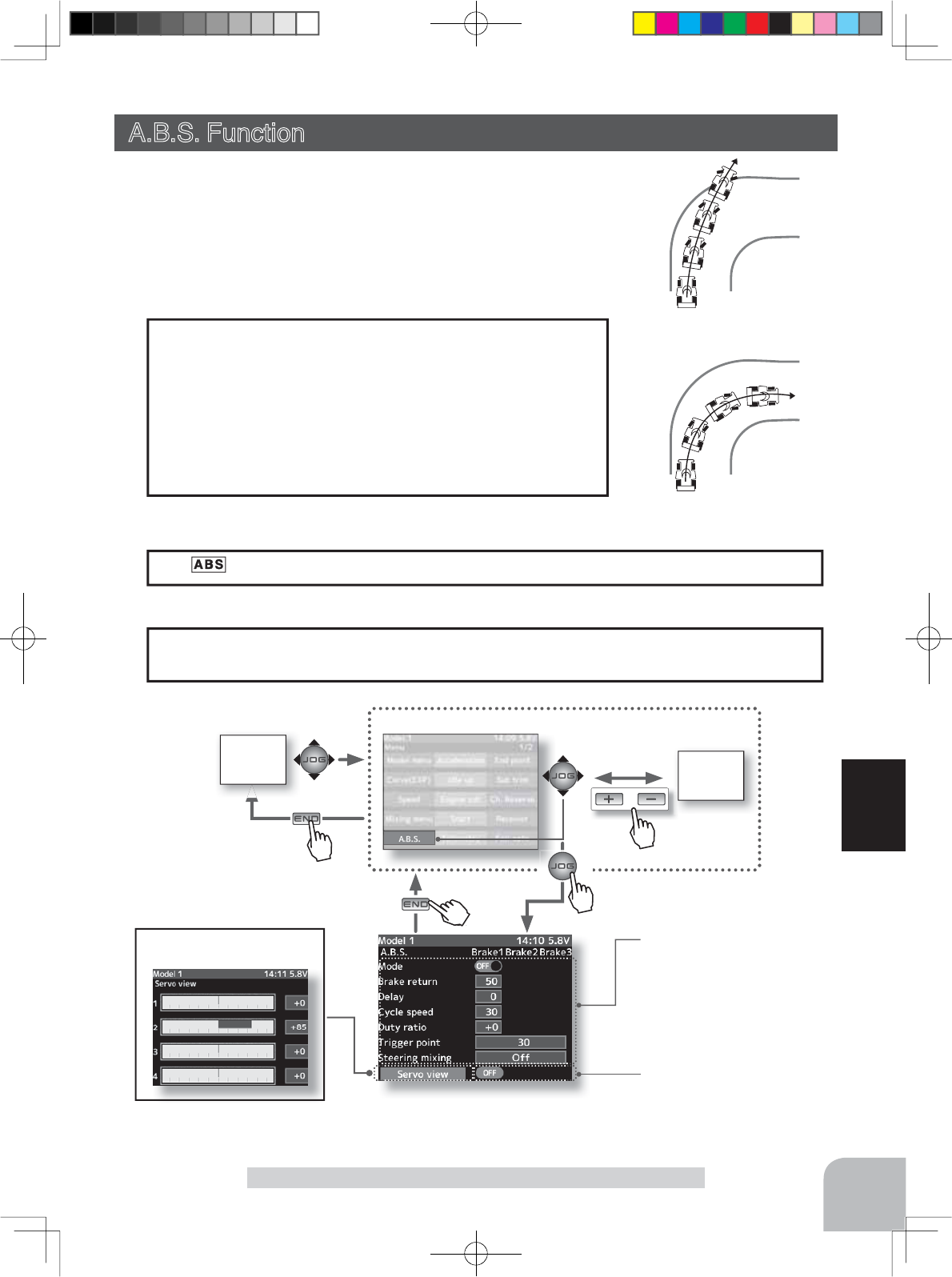
With A.B.S.
Without A.B.S.
Setup items
Mode (Function On/Off)
Brake return amount
Delay amount
Cycle speed
Trigger point
Duty ratio
Steering mixing
HOME
screen
or
MENU 1 screen
The servo view screen is
displayed.
When brake operation enters
the ABS set range, several
"ON" are displayed.
Pres
s
Pres
s
Pres
s
Pu h
Pres
s
73
Function
A.B.S Function
The display appears on the home screen.
Operation display
MENU 2
screen
When trigger ratio (p.66) was set to 100:0, brake operation stops, and the servo does not
operate even if the ABS function is set.
When trigger ratio was set to 100:0
- When the brakes are applied, the throttle servo will pulse
intermittently. This will have the same effect as pumping
the brakes in a full size car.
- The brake return amount, pulse cycle, and brake duty can
be adjusted.
- The region over which the ABS is effective can be set ac-
cording to the steering operation. (Mixing function)
Operation
A.B.S. Function (Throttle system)
When the brakes are applied while cornering with a 4 Wheel Drive
or other type of vehicle, understeer may occur. The generation of
understeer can be eliminated and corners can be smoothly cleared
by using this function.
4PX-Eng-08-Function-66-103.indd 73 2014/07/18 17:20:31
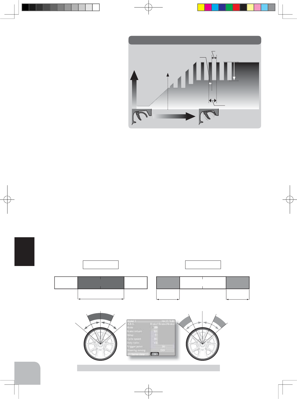
L 50% 50%N R L 50% 50%NR
Servo travel
Trigger operation
B
rake return
Trigger point
Cycle speed
Duty ratio: X and Y ratio
X: (Brake application time)
Y: (Brake return time)
A.B.S
74
Function
A.B.S Function
Steering operationSteering operation
A.B.S. operation range A.B.S. operation range A.B.S. operation range
N50% E50%
- Mode : Function ON/OFF
ABS function ON/OFF setting.
When using the ABS function, set
to "ON".
- Brake return
Sets the rate at which the servo
returns versus trigger operation
for brake release. When set to
0%, the ABS function is not per-
formed. When set to 50%, the ser-
vo returns 50% (1/2) of the trigger
operation amount and when set
to 100%, the servo returns to the
neutral position.
- Delay
Sets the delay from brake operation to ABS operation. When set to 0%, the ABS func-
tion is activated without any delay. At 50%, the ABS function is activated after a delay of
approximately 0.7 second and at 100%, the ABS function is activated after a delay of ap-
proximately 1.4 seconds.
- Cycle speed
Sets the pulse speed (cycle speed). The smaller the set value, the faster the pulse cycle.
- Duty ratio
Sets the proportion of the time the brakes are applied and the time the brakes are released
by pulse operation. The ratio can be set to +3 ~ 0 ~ -3 in 7 steps.
- Trigger point
Sets the trigger point at which the ABS function begins to operate at brake operation.
- Steering mixing
Sets ABS operation ON/OFF according to the steering operation range.
4PX-Eng-08-Function-66-103.indd 74 2014/07/18 17:20:31
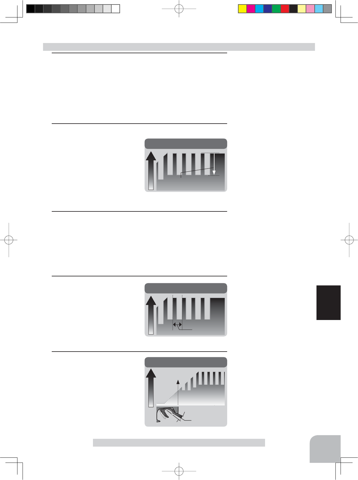
B
rake return
(Amount of brake return)
B
rake return
Servo travel
Cycle speed
Servo travel
Cycle
Trigger point
Servo travel
Trigger point
Trigger point
Brake side
Neutral
A.B.S. function adjustment
- Brake return amount is influ-
enced by the "EXP" rate on the
brake side.
Delay amount
0 ~ 100
Initial value: 0
Adjustment buttons
- Use the (+) and (-) buttons to
make adjustments.
- Return to the initial value by
pressing the (+) and (-) buttons
simultaneously (approx. 1 sec).
Return amount
0 ~ 50 ~ 100
Initial value: 50
Function ON/OFF (Mode)
ON,OFF
Setup item selection
- Select by (JOG) button up,
down, left or right operation.
Cycle speed
1 ~ 100
Initial value: 10
Trigger point
5 ~ 95
Initial value: 30
75
Function
A.B.S Function
1(Function ON/OFF)
Select the setting item "Mode" by (JOG) button up, down, left
or right operation. Set the function to the active state by press-
ing the (+) or (-) button.
"OFF" :Function OFF
"ON" :Function ON
2(Brake return amount adjustment)
Select the setting item "Brake
return" by (JOG) button up,
down, left or right operation.
Use the (+) or (-) button to ad-
just the return amount.
"0" :No return
"50" :Return to the 50% position of the brake operation amount
"100" :Return to the neutral position.
3(Delay amount setup)
Select the setting item "Delay" by (JOG) button up, down, left
or right operation. Use the (+) or (-) button to adjust the delay
amount.
"0" :A.B.S. function performed without any delay
"50" :A.B.S function performed after an approximate 0.7 sec delay.
"100" :A.B.S. function performed after an approximate 1.7 secs delay.
4(Cycle speed adjustment)
Select setting item "Cycle
speed" by (JOG) button up,
down, left or right operation.
Use the (+) or (-) button to ad-
just the pulse speed (cycle).
- The smaller the set value, the faster the pulse speed.
5(Trigger point setup)
Select setting item "Trigger
point" by (JOG) button up,
down, left or right operation.
Use the (+) or (-) button to ad-
just the operation point.
- Sets the throttle trigger position at
which the A.B.S. function is per-
formed. The number is the % dis-
play with the full brake position made 100.
4PX-Eng-08-Function-66-103.indd 75 2014/07/18 17:20:32
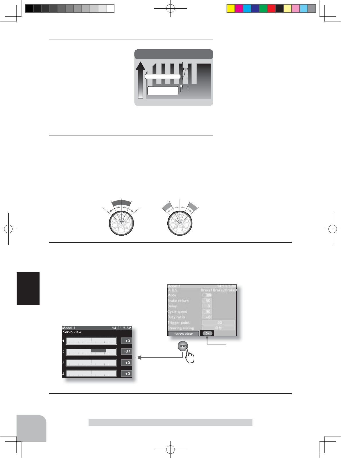
Neutral range End point range
Servo view screen
Duty ratio
Servo travel
Duty ratio: X and Y ratio
X: (Brake
application time)
Y: (Brake return time
Pres
s
76
Function
A.B.S Function
Steering operation
6(Cycle duty ratio setup)
Select setting item "Duty
ratio" by (JOG) button up,
down, left or right operation.
Use the (+) or (-) button to
adjust the duty ratio.
"-3" :Brake application time becomes shortest. (Brakes lock with difficulty)
"+3" :Brake application time becomes longest (Brakes lock easily)
(Remark) For low grip, set at the - side and for high grip, set at the + side.
7(Steering mixing setup)
Select setting item "Steering mixing" by (JOG) button up,
down, left or right operation. Use the (+) or (-) button to ad-
just the steering mixing range.
- Sets the range within which the A.B.S. function is performed relative to
steering wheel operation.
Duty ratio
-4 ~ 0 ~ +4
Initial value: 0
Steering mixing
Off,
Neutral10 ~ 100,
End point10 ~ 100
Initial value: OFF
8When ending setting, return to the initial screen by pressing the (END) button twice (for
function menu screen, press the (END) button once).
9When ending setting, return to the menu screen by pressing the (END) button.
When ABS is active (when the
servo is polling), "OFF" at the
bottom of the screen switches
to "ON".
4PX-Eng-08-Function-66-103.indd 76 2014/07/18 17:20:32
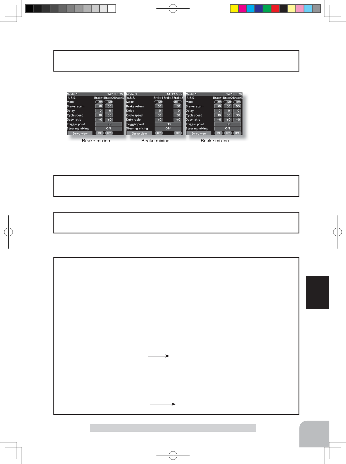
Beake mixing
Brake 2 "ON"
Beake mixing
Brake 3 "ON"
Beake mixing
Brake 2&3 "ON"
Setup items
Mode (Function On/Off)
Brake return amount
Delay amount
Cycle speed
Duty ratio
77
Function
A.B.S Function
Setting items other than trigger point and steering mixing can be adjusted independently.
Use PS1~PS5 to switch the A.B.S. function ON/OFF.
See the function select switch function. (p.99)
Switch setting
The brake return amount, delay amount and cycle speed can be controlled with digital
trim DT1~DT5 or digital dial DL1 etc. with the function select dial function. (p.101)
Dial / Trim Setting
- Basic setting
Brake return: Approx. 30% (If this value is too high, the braking distance will increase.)
Cycle speed: 5~7
Duty ratio: 0 (When grip is low: - side, when grip is high: + side)
Delay : 10~15%
Trigger point: Approx. 70%
Steering mixing: Off
- When the wheels lock, or the car spins, when the brakes are applied fully
Brake return: Increase from 30%
Duty ratio: Shift from 0 to - side (-1, -2, -3)
Delay : Reduce the delay
- When the braking effect is poor and the braking distance is long when the brakes are
applied fully
Brake return: Decrease from 30%
Duty ratio: Shift from 0 to + side (+1, +2, +3)
DLY: Increase the delay
Example of A.B.S. function setting when S9353HV used
(There will be a slight difference depending on the state of the linkage.)
ABS can be independently set for the brakes which are controlled by the Brake2 and
Brake3 (3rd CH and 4th CH) by using the brake mixing function described on page 80.
1/5 scale car and other independent brakes and ABS
4PX-Eng-08-Function-66-103.indd 77 2014/07/18 17:20:33

78
Function
Mixing Menu
Mixing Menu (Steering,Throttle,3rd,4th channel system)
Big cars such as 1/5 scale GP car, etc. brake mixing, 4-wheel steering 4WS mixing used
with Corolla, etc., dual ESC mixing that controls the front and rear motors independently,
gyro mixing that allows adjustment of the sensitivity of Futaba car rate gyros, CPS mixing
that controls Futaba channel power switch CPS-1, and other special mixing functions and
program mixing that allows free setting among channels can be set at the mixing menu.
Program, mixing
These functions allow you to apply mixing between the steering, throttle, channel 3 and
channel 4.
Steering mixing
This mixing function uses 2 servos to individually control the left and right steering. Left
and right steering can be set independently so smooth cornering is possible.
Brake mixing
This function is used when the front and rear brakes must be adjusted independently such
as a 1/5 scale GP car.
Gyro mixing
This function is a remote gain function that uses the 3rd or 4th CH of the transmitter to ad-
just the sensitivity of a Futaba car rate gyro. It can also be used by switching the two gains
mode by switch. Normal mode and AVCS mode are explained at gyro mixing.
4WS mixing
This function can be used with Corolla and other 4WS type vehicles. It is mixing that uses
the 1st CH to control the front side steering and the 3rd or 4th CH to control the rear side
steering. OFF (front side only), reverse phase, same phase, rear side only and other 4WS
types are switched by switch.
Dual ESC mixing
This function is mixing that uses the 2nd CH to control the front side motor controller and
the 3rd or 4th CH to control the rear side motor controller of a Corolla or other 4WD type
vehicle. Drive is switched among front side only, rear side only, and both front side and rear
side (4WD) by switch.
CPS mixing
This function controls the Futaba CPS-1 channel power switch.
Normally, when a CPS-1 unit is used to light the chassis dress-up and other illumination
(LED) the LED is connected to a vacant switch channel of the connected CPS-1 unit and
the LED is turned on and off by switch while the vehicle is running. However, when this
&36PL[LQJIXQFWLRQLVXVHGWKH/('FDQEHWXUQHGRQDQGRIIDQGDOVRÀDVKHGLQVWHSZLWK
steering and throttle operation, as well as being turned on and off by switch.
Tilt mixing
Tilt mixing uses an outboard engine and applies bidirectional mixing from rudder (steering)
WRÀDSDQGIURPÀDSWRUXGGHUVRWKDWZLWKDERDWUXGGHURSHUDWLRQDQGWLOWPL[LQJRSHUD-
tion can be performed by 2 servos.
4PX-Eng-08-Function-66-103.indd 78 2014/07/18 17:20:34
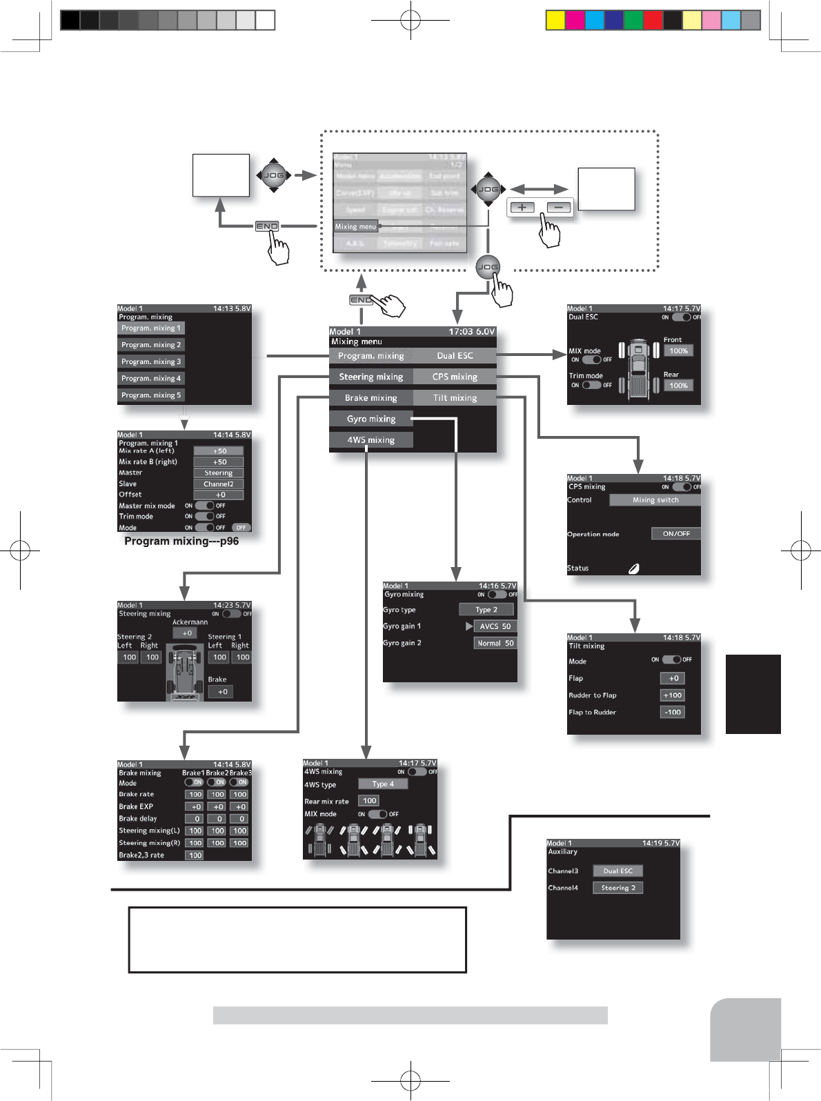
HOME
screen MENU 2
screen
or
MENU 1 screen
Steering mixing---p84
Brake mixing---p80 4WS mixing---p86
Tilt mixing---p94
Gyro mixing---p88
CPS mixing---p92
Dual ESC mixing---p90
Program mixing---p96
Pres
s
Pres
s
Pres
s
Pu h
Pres
s
79
Function
Mixing Menu
Since the mixing function can be assigned to CH3 and CH4,
all mixings cannot be used simultaneously. Since program
mixing is free, it can be used even when other mixings are
active, but they interact. The mixing used can be confirmed on
the Auxility screen. (p.155)
4PX-Eng-08-Function-66-103.indd 79 2014/07/18 17:20:34
80
Function
Brake Mixing
Brake Mixing (Throttle, 3rd, 4th channel system)
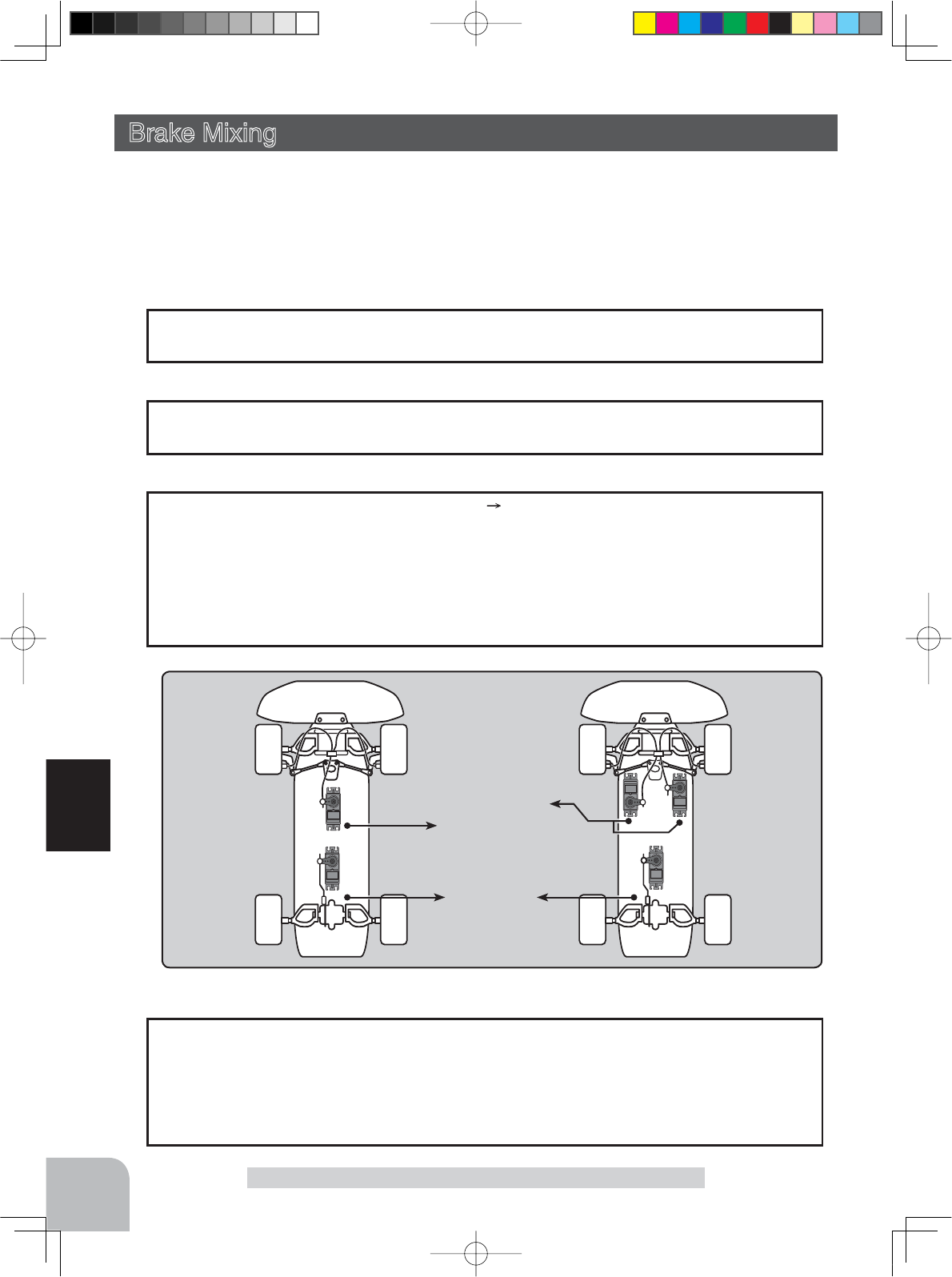
This function is used when the front and rear brakes must be adjusted independently such
as a 1/5 scale GP car. This mixing uses the 2nd CH for the rear brakes and the 3rd or 4th
CH for the front brakes, or controls the front brakes with the 3rd CH and 4th CH servos, or
controls the 2nd CH by independent throttle and controls the rear and front brakes with the
3rd CH and 4th CH. In addition, mixing which varies the 3rd CH and 4th CH brake rate in
proportion to steering operation is also possible.
-When braking, mixing is applied to 2nd CH 3rd CH, 4th CH.
-3rd CH and 4th CH brake amount, 2nd CH, 3rd CH, and 4th CH brake delay, and 3rd
CH and 4th CH brake EXP and ABS can be set.
-Steering mixing which varies front brakes 3rd CH and 4th CH matched to the steering
operation can be set. Front brakes 3rd CH and 4th CH can be individually weakened ac-
cording to the steering left or right operation amount.
Operation
Front Brake
Brake2/3
Rear Brake
Brake1
or Brake2/3
Brakes 2 and 3 can also use the ABS function (p.73) by brake mixing. All setting items
other than trigger point and steering mixing can be set for front brake 2 and 3 use only.
Brake 2 and 3 can also use the ABS function independently even when the brake 1 (CH2)
ABS function is OFF. The ABS (brake 2 and 3) function can be set ON/OFF by switch
function. (p.99)
3rd, 4th chnnels A.B.S.
The mixing function is assigned to CH3 and CH4. Channels used by other mixing can-
QRWEHXVHG:KHQWKHQXPEHURIFKDQQHOVLVLQVXI¿FLHQWFDQFHOWKHRWKHUPL[LQJ
When the throttle mode (P66) was set to 100:0, brake operation stops. When using brake
mixing, set the throttle mode to 70:30 or 50:50.
When trigger ratio was set to 100:0
4PX-Eng-08-Function-66-103.indd 80 2014/07/18 17:20:34
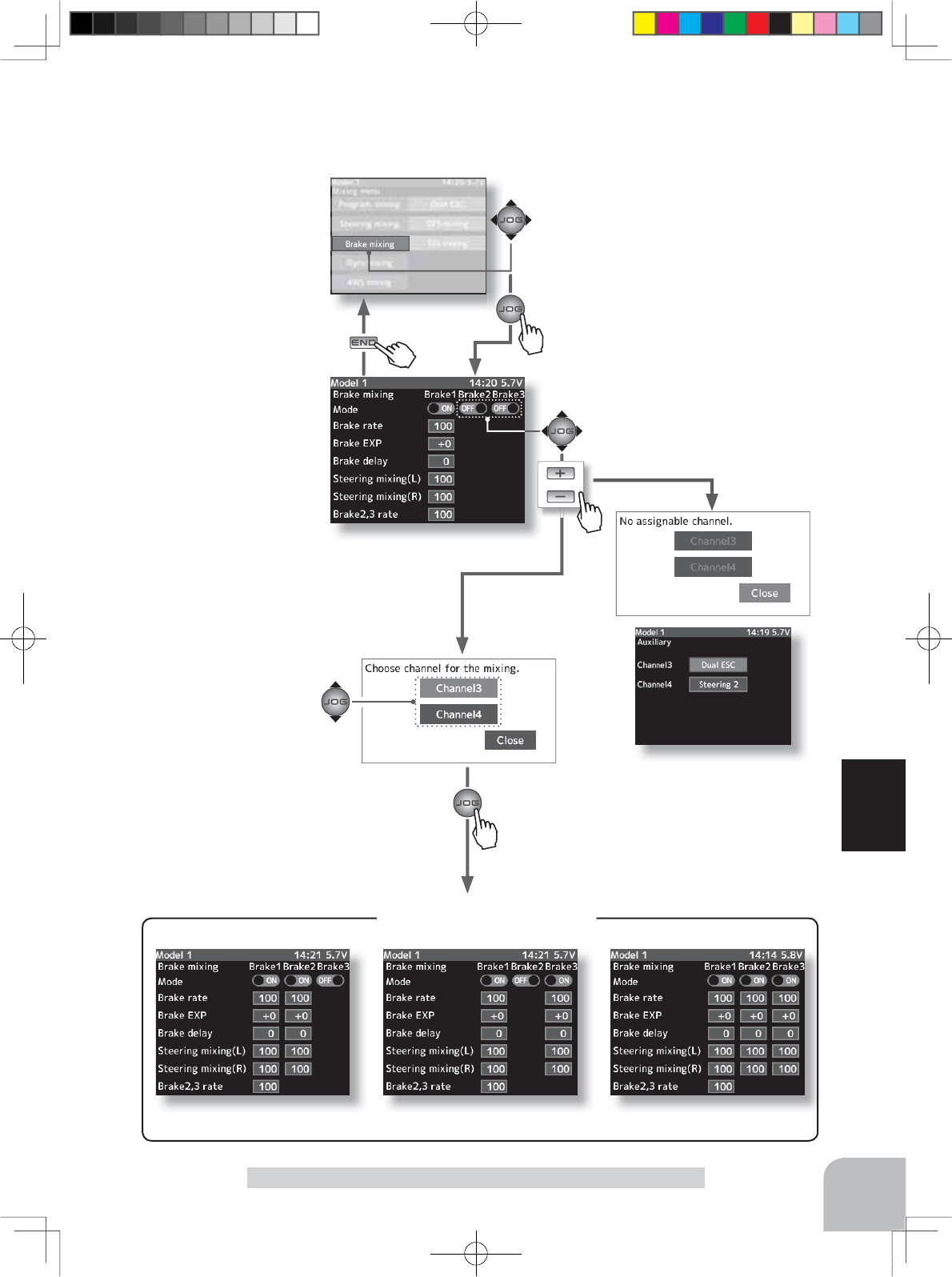
Brake 2 ON Brake 3 ON Brake 2 & 3 ON
Brake mixing ON
Mixing menu screen
Pres
s
Pu h
Pres
s
81
Function
Brake Mixing
When the brake 2 or 3 mixing mode is
set to "ON", the brake 2 or 3 channel
setup screen is displayed.
Channel is selected by
(JOG) button operation.
When channels 3 and 4 are used
by other mixing, the message "No
assignable channel" is displayed.
The mixing used can be confirmed on
the Auxility screen. (p.155)
or
Brake mixing screen from mixing menu screen (p.79)
Pres
s
Pres
s
4PX-Eng-08-Function-66-103.indd 81 2014/07/18 17:20:35
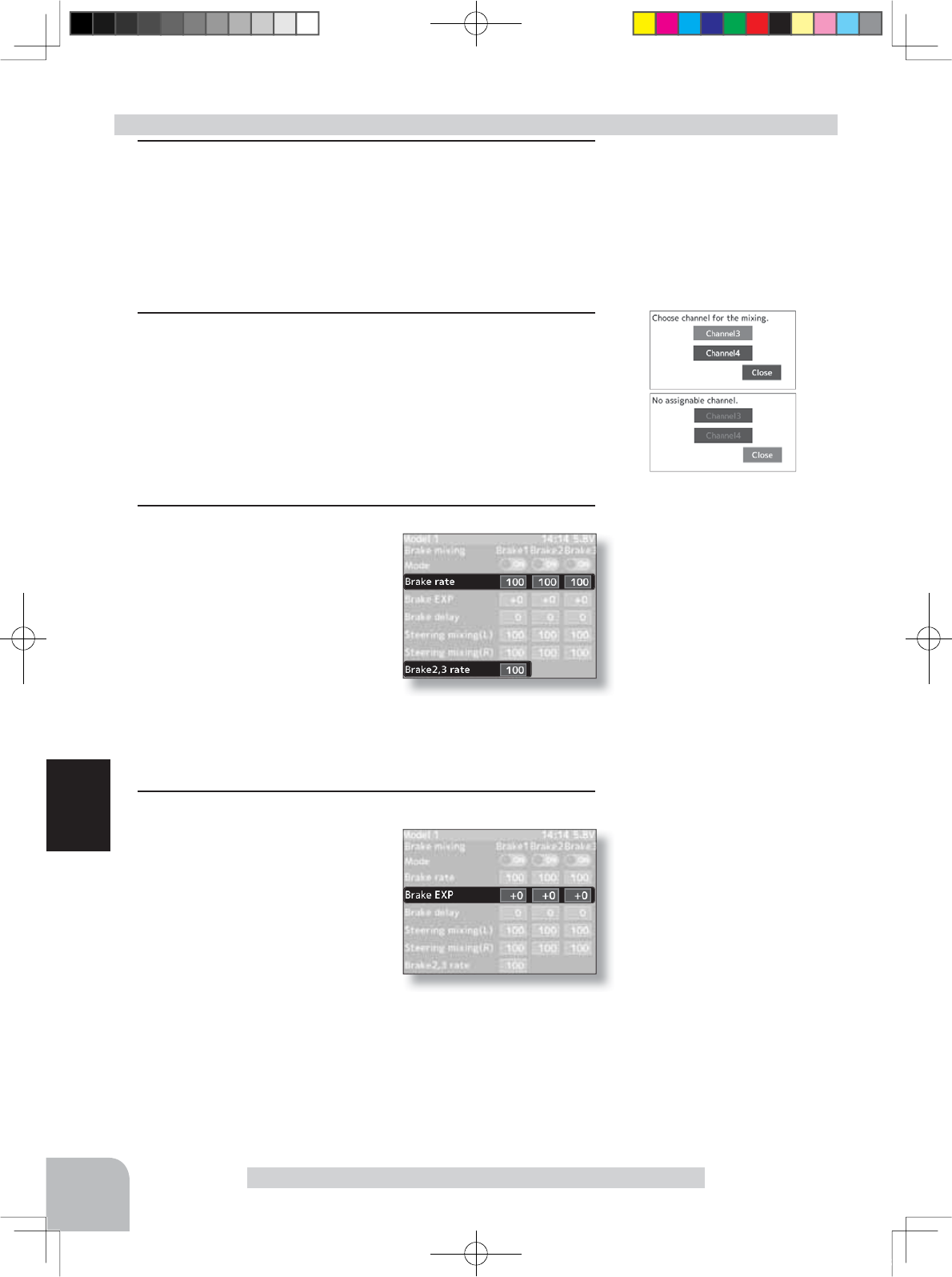
Setting buttons
- Use the (+) and (-) buttons to
make adjustments.
Function ON/OFF (Mode)
ON, OFF
Adjustment buttons
- Use the (+) and (-) buttons to
make adjustments.
- Return to the initial value by
pressing the (+) and (-) buttons
simultaneously (approx. 1 sec).
Brake rate
0 ~ 100
Initial value:100
Adjustment buttons
- Use the (+) and (-) buttons to
make adjustments.
- Return to the initial value by
pressing the (+) and (-) buttons
simultaneously (approx. 1 sec).
Brake EXP rate
-100 ~ 0 ~ +100%
Initial value:0
82
Function
Brake Mixing
1(Function ON/OFF)
Select the setting items "Mode Brake2" or "Mode Brake3" by
(JOG) button up, down, left or right operation. Set the func-
tion to the active state by pressing the (+) or (-) button.
"OFF" :Function OFF
"ON" :Function ON
2(Select channel)
The screen that sets the channel used by brake 2 or brake 3
is displayed. Select channel 3 or channel 4 by (JOG) button
up or down operation, and press the (JOG) button.
If channels 3 and 4 are used by other mixing, the message "No assigna-
ble channel" is displayed. Set the other mixing to "OFF". The mixing used
can be checked at the auxiliary channel screen. (p.155)
3(Brake 2 & 3 rate)
Select setup items "Brake2
rate" or "Brake3 rate" by (JOG)
button up, down, left or right op-
eration, and use the (+) and (-)
buttons to adjust the Brake rate
amount.
- When adjusting the brake amount of both brakes after individually adjust-
ing the Brake2 and Brake3, select "Brake2,3 rate".
-The brake 1 rate is linked with throttle channel (ATL) setting.
4(Brake 2 & 3 -EXP)
With the jog dial, move the
blinking cursor up/down, left or
right to select "Brake2 -EXP or
Brake3 -EXP". Use the plus
(+) button to adjust for a faster
brake response or use the mi-
nus (-) button for a slower or
milder brake response.
-When using Brake2 and Brake3 servos as front brakes and using EXP, set
the Brake2-EXP amount and Brake3- EXP amount separately.
-Brake 1 EXP is linked with throttle curve (brake EXP) setting.
Brake mixing adjustment
4PX-Eng-08-Function-66-103.indd 82 2014/07/18 17:20:35
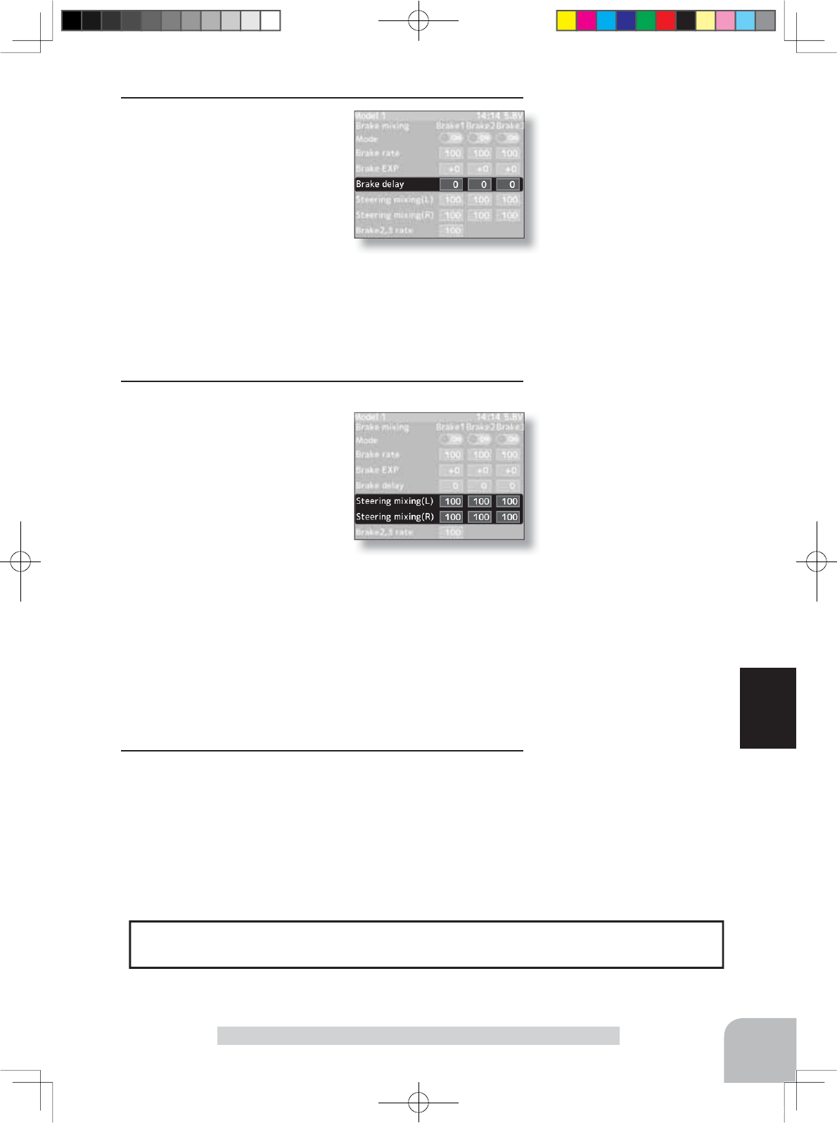
Adjustment buttons
- Use the (+) and (-) buttons to
make adjustments.
- Return to the initial value by
pressing the (+) and (-) buttons
simultaneously (approx. 1 sec).
Delay amount
100 ~ 0
Initial value:0
Adjustment buttons
- Use the (+) and (-) buttons to
make adjustments.
- Return to the initial value by
pressing the (+) and (-) buttons
simultaneously (approx. 1 sec).
Brake rate
Steering mixing(L)
Steering mixing(R)
0 ~ 100
Initial value:100
5(Delay amount setup)
Select setup items "Brake1"
Delay or Brake2,3 -Delay" by
(JOG) button up, down, left or
right operation, and use the (+)
and (-) buttons to adjust the
delay amount.
-Since a delay at all the brakes is dangerous, a delay is not applied to the
brake to be adjusted last.
For example, when brakes 1, 2, and 3 are all used, when a delay is ap-
plied to brakes 2 and 3, a delay cannot be applied to brake 1. When a de-
lay must be applied to brake 1, the brake 2 or brake 2 delay must be set
to "0".
6(Steering mixing)
Use this function when you
want to weaken the brakes
when steering was operated.
Select the setting item "Steer-
ing mixing(L)" or "Steering
mixing(R)" by (JOG) button up,
down, left, or right operation.
Use the (+) or (-) button to ad-
just the brake amount.
Use "Steering mixing(R)" Brake1,2,3 to adjust the brake
amount relative to the steering right operation amount. and
"Steering mixing(L)" Brake1,2,3 to adjust the brake amount
relative to the steering left operation amount. The smaller
the value, the weaker the front brakes. Set value "100" is the
state in which steering mixing is not performed.
- The mixing amount can be adjusted in a range from 0 to 100.
7When ending setting, return to the Mixing menu screen by
pressing the (END) button.
The function select dial function can control the brake 1,2,3 rate , delay amount and EXP
setting using digital dial or digital trim. (p.101)
Dial / Trim Setting
83
Function
Brake Mixing
4PX-Eng-08-Function-66-103.indd 83 2014/07/18 17:20:35
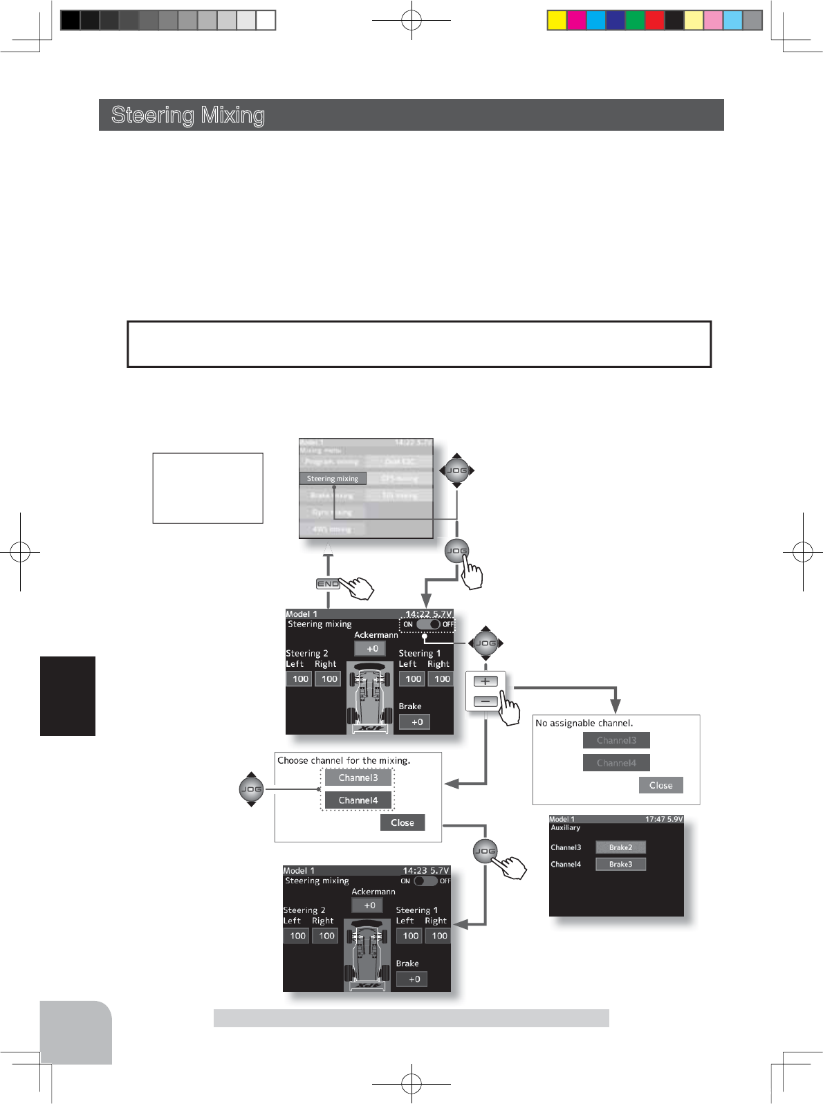
Mixing menu screen
Pres
s
Pu h
Pres
s
84
Function
When steering mixing is set
to "ON", the steering 2 chan-
nel setup screen is displayed.
When channels 3 and 4 are used
by other mixing, the message
"No assignable channel" is dis-
played.
or
Steering Mixing
The mixing function is assigned to CH3 and CH4. Channels used by other mixing can-
QRWEHXVHG:KHQWKHQXPEHURIFKDQQHOVLVLQVXI¿FLHQWFDQFHOWKHRWKHUPL[LQJ
Steering mixing screen from mixing menu screen (p.79)
Brake
On
Steering Mixing (Steering, 3rd or 4th channel system)
This mixing function uses 2 servos to individually control the left and right steering. Left
and right steering can be set independently so smooth cornering is possible.
The right side steering servo or the left side steering servo connects to receiver CH1 and the
other side connects to receiver CH3 or CH4. The channel to which the left and right servo
FRQQHFWVLVQRWVSHFL¿HG$IWHUWKHOHIWDQGULJKWVHUYRVDUHDGMXVWHGLQGLYLGXDOO\$FNHUPDQ
can also be adjusted by Ackerman rate.
In addition, the left and right steering are operated in the opposite direction by switch. An
emergency brake function by steering can also be set.
Pres
s
Pu h
Pres
s
The mixing used can be confirmed on
the Auxility screen. (p.155)
Channel is selected by
(JOG) button operation.
When an emergency brake
function is set, the function
ON/OFF is displayed in a
pop-up window on the home
screen.
4PX-Eng-08-Function-66-103.indd 84 2014/07/18 17:20:35
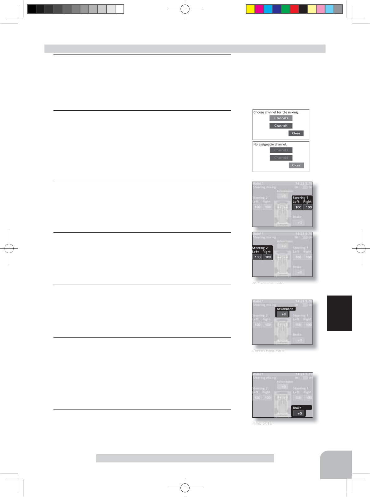
Setting buttons
- Use the (+) and (-) buttons to
make adjustments.
Function ON/OFF
ON, OFF
Left / Right rate
0~100 Initial value:100
Ackermann rate
-100~0~+100 Initial value:100
Brake rate
-100~0~+100 Initial value:100
85
Function
Steering Mixing
1(Function ON/OFF)
Select the setting items "ON-OFF" by (JOG) button up, down,
left or right operation. Set the function to the active state by
pressing the (+) or (-) button.
"OFF" :Function OFF
"ON" :Function ON
2(Channel setup)
A screen at which the channel to be used by steering 2 is
displayed. Select channel 3 or channel 4 connected to a ser-
vo during preparation by (JOG) button up or down operation,
and press the (JOG) button.
- If channels 3 and 4 are used by an another mixing, the message "No as-
signable channel" is displayed. Set the other mixing to OFF. Mixing can be
checked at the auxiliary channel screen. (P155)
3
(Steering 1 and receiver CH1 servo steering angle adjustment)
Select the steering 1 left or right "Rate" by (JOG) up, down,
left, or right operation.
Turn the steering wheel fully to the left or right and adjust the
left and right steering amounts by (+) or (-) button.
4
(Steering 2 and receiver CH3 or 4 servo steering angle adjustment)
Select steering 2 left or right "Rate" by (JOG) button up,
down, left, or right operation.
Turn the steering wheel fully to the left and right and adjust
the left and right steering amounts by (+) and (-) button.
5 (Ackerman adjustment)
Select the Ackerman "Rate" by (JOG) button up, down, left,
or right operation.
Adjust the left and right differential amount and adjust the
Ackerman by (+) and (-) button.
6 (Emergency brake)
(Preparations)
·When using this function, set the switch with the Switch
Select function. (p.99)
Select the emergency brake "Rate" by (JOG) button up,
down, left, or right operation. Adjust the steering 1/2 operation
position by (+) and (-) button.
7When ending setting, return to the Mixing menu screen by
pressing the (END) button.
Steering mixing adjustment
4PX-Eng-08-Function-66-103.indd 85 2014/07/18 17:20:36
Mixing menu screen
Pres
s
Current mode displayed
on home screen
Pu h
Pres
s
86
Function
4WS Mmixing
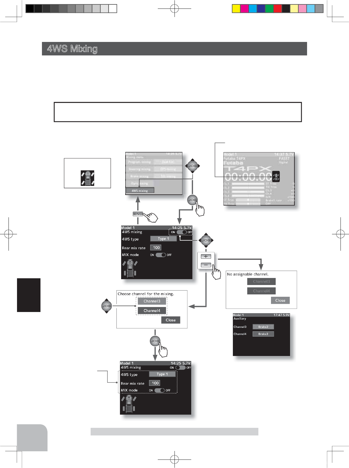
This function can be used with crawlers and other 4WS type vehicles. It is mixing that uses
the 1st CH to control front side steering and the 3rd CH to control rear side steering.
OFF (front side only), reverse phase, same phase, rear side only, and other 4WS type switch-
ing is used by selecting PS1, PS2, PS4 or PS5 with the function select function (p.99).
4WS Mixing (Steering, 3rd or 4th channel system)
or
4WS mixing
Type3
When the mode is switched
by switch, a pop-up window
is displayed on the home
screen to announce the new
mode.
The mixing function is assigned to CH3 and CH4. Channels used by other mixing can-
QRWEHXVHG:KHQWKHQXPEHURIFKDQQHOVLVLQVXI¿FLHQWFDQFHOWKHRWKHUPL[LQJ
Pres
s
Pres
s
The mixing used can be confirmed on
the Auxility screen. (p.155)
4WS mixing screen from mixing menu screen (p.79)
When channels 3 and 4 are used
by other mixing, the message
"No assignable channel" is dis-
played.
When 4WS mixing is set to
"ON", the rear steering chan-
nel setup screen is displayed.
Channel is selected by
(JOG) button operation.
Setup items
4WS type
Rear mix rate
Mix mode
4PX-Eng-08-Function-66-103.indd 86 2014/07/18 17:20:36
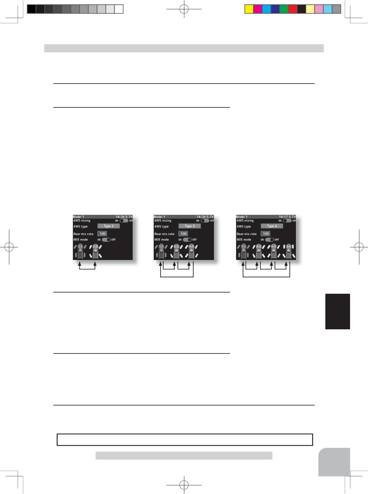
Setting buttons
- Use the (+) and (-) buttons to
make adjustments.
Function ON/OFF (4WS type)
Type1(OFF), Type2,
Type3, Type4
Setting buttons
- Use the (+) and (-) buttons to
make adjustments.
Mixing mode (MX Mode)
OFF, ON
Initial value: OFF
Adjustment buttons
- Use the (+) and (-) buttons to
make adjustments.
- Return to the initial value by
pressing the (+) and (-) buttons
simultaneously (approx. 1 sec).
Rear rate (Rear mix rate)
0 ~ 100
Initial value:100
87
Function
4WS Mmixing
Type2
Front side only, Reverse
phase switching
Type3
Front side only, Reverse phase
and same phase switching
Type4
Front side only, reverse phase, same
phase, and rear side only switching
(Preparation)
- Since this function is used by switching the type of 4WS with a switch, the switch used by the
function select switch function (p.99) is set.
1 (4WS mixing function ON/OFF and channel setup)
Refer to the left page and set the function to ON and set the mixing channel.
4WS mixing adjustment
2(4WS type selection)
Operate the (JOG) button up and down and select the set-
ting item "4WS type". Select the type by pressing the (+) or (-)
button.
"Type1" :Function OFF (front only)
"Type2" :Front side only, reverse phase switching
"Type3" :Front side only, reverse phase and same phase switching
"Type4" :Front side only, reverse phase, same phase, and rear side only switching
Switched in the order shown in the figure below by set SW
3(Rear side travel adjustment)
Operate the (JOG) button up and down and select setting
item "Rear mix rate". Adjust the rear side travel with the (+)
or (-) button.
The mixing amount can be adjusted by using the function dial function. (p.101)
Dial / Trim Setting
4(Mix mode setting)
Operate the (JOG) button up and down and select the setting
item "MX mode". Set the mix mode with the (+) or (-) button.
"OFF" :The EXP function of the 1st CH and other settings are not mixed.
"ON" :The EXP function of the 1st CH and other settings are mixed.
5When ending setting, return to the Mixing menu screen by pressing the (END) button.
4PX-Eng-08-Function-66-103.indd 87 2014/07/18 17:20:36
or
Mixing menu screen
Pres
s
Pres
s
Pres
s
Pres
s
88
Function
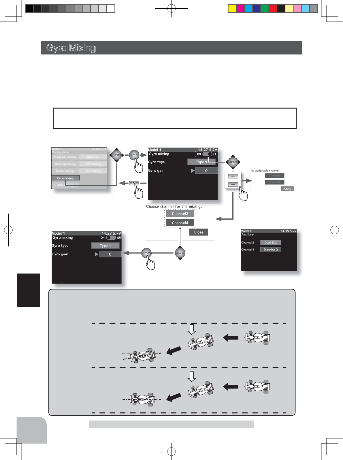
This function is a remote gain function which adjusts the sensitivity of the Futaba car rate
gyro at the T4PX side, and is mixing that uses the 3rd or 4th CH to adjust the gyro sensitiv-
ity. When using the T4PX by switching the AVCS and normal modes use PS1- PS5 with the
function select switch function (p.99).
For a description of the car rate gyro mounting method and handling, refer to the rate gyro
instruction manual.
Gyro Mixing (Steering system)
Gyro Mixing
AVCS / NORMAL Modes
The gyro has 2 operating modes: NORMAL mode and AVCS mode. In the AVCS mode, the angle is
controlled simultaneously with NORMAL mode rate control (swing speed). The AVCS mode increas-
es straight running stability more than that of the NORMAL mode. Because the feel of operation is
different, choose your favorite mode.
NORMAL
Countersteers against outside
force, but cannot correct the
skid direction.
AVCS
Corrects the skidding direc-
tion and forcefully maintains
the heading.
Outside
force
Outside
force
The mixing function is assigned to CH3 and CH4. Channels used by other mixing can-
QRWEHXVHG:KHQWKHQXPEHURIFKDQQHOVLVLQVXI¿FLHQWFDQFHOWKHRWKHUPL[LQJ
The mixing used can be confirmed on
the Auxility screen. (p.155)
Gyro mixing screen from mixing menu screen (p.79) When channels 3 and 4
are used by other mix-
ing, the message "No
assignable channel" is
displayed.
Channel is selected by
(JOG) button operation.
When Gyro mixing is set to
"ON", the gain steering chan-
nel setup screen is displayed.
4PX-Eng-08-Function-66-103.indd 88 2014/07/18 17:20:37
Setting buttons
- Use the (+) and (-) buttons to
make adjustments.
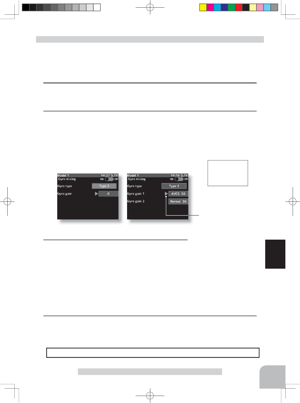
Gyro tyoe
Type1, Type2
Initial value: Type1
Adjustment buttons
- Use the (+) and (-) buttons to
make adjustments.
- Return to the initial value by
pressing the (+) and (-) buttons
simultaneously (approx. 1 sec).
Gain
AVCS120 ~ 0 ~ Normal120
Initial value:0
89
Function
Gyro Mixing
Gyro mixing
AVCS:50
When the gain is switched by
a switch, a pop-up window
appears on the home screen
to announce the gain.
(Preparation)
- Refer to the gyro instruction manual and connect the gyro to the receiver. When using remote
gain, connect gyro sensitivity adjustment to the 3rd or 4th CH of the receiver.
- When using gyro mixing by switching between the NORM (normal) and AVCS modes, use
the function select switch function (p.99) to set the switch to be used.
1(Gyro mixing function ON/OFF and channel setup)
Refer to the left page and set the function to ON and set the mixing channel.
2(Gyro mixing type selection)
Operate the (JOG) button up and down and select the set-
ting item "Gyro type". Select the type by pressing the (+) or (-)
button.
"Type1" :One mode only
"Type2" :Switching Gyero gain 1 and Gyero gain 2
Gyro mixing adjustment
3(Gyro gain1 side gain adjustment)
Operate the (JOG) button up and down and select setting
item "Gyro gain1". Adjust the Gyro gain1 side gain with the (+)
or (-) button.
(Gyro gain2 side gain adjustment)
Operate the (JOG) button up and down and select setting
item "Gyro gain2". Adjust the Gyro gain2 side gain with the (+)
or (-) button.
The gain amount can be adjusted by using the function dial function. (p.101)
Dial / Trim Setting
Shows the gyro mode select
switch mode.
4When ending setting, return to the Mixing menu screen by pressing the (END) button.
4PX-Eng-08-Function-66-103.indd 89 2014/07/18 17:20:37
Mixing menu screen
Pres
s
Pres
s
Current mode displayed
on home screen
Pu h
Pres
s
90
Function
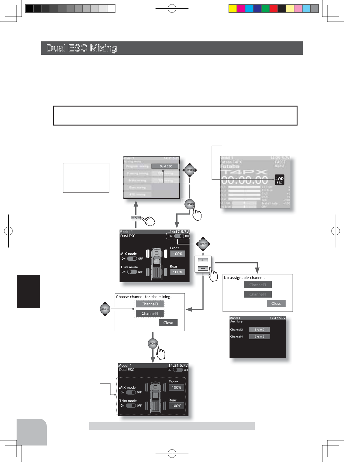
DUAL ESC Mixing
or
Dual ESC(4WD)
4WD
This function is mixing used with crawlers and other 4WD type vehicles and uses the 2nd
CH to control the rear motor controller and the 3rd or 4th CH to control the front motor con-
troller.
Front drive only, rear drive only, and both front and rear drive (4WD) switching can be per-
formed by trim dial or by setting a switch for each mode.
Dual ESC Mixing (Throttle system)
The mixing function is assigned to CH3 and CH4. Channels used by other mixing can-
QRWEHXVHG:KHQWKHQXPEHURIFKDQQHOVLVLQVXI¿FLHQWFDQFHOWKHRWKHUPL[LQJ
Setup items
Drive Ratio (Front & Rear)
Mix mode
Trim mode
Pres
s
The mixing used can be confirmed on
the Auxility screen. (p.155)
When channels 3 and 4 are used
by other mixing, the message
"No assignable channel" is dis-
played.
When Dual ESC mixing is set
to "ON", the front drive ESC
channel setup screen is dis-
played.
Dual ESC mixing screen from mixing menu screen (p.79)
Channel is selected by
(JOG) button operation.
When the drive mode is
switched by a switch, a pop up
window appears on the home
screen to announce the mode.
4PX-Eng-08-Function-66-103.indd 90 2014/07/18 17:20:38
Adjustment buttons
- Use the (+) and (-) buttons to
make adjustments.
- Return to the initial value by
pressing the (+) and (-) buttons
simultaneously (approx. 1 sec).
Drive ratio
Front 0%:Rear 100%
~ Front 100%:Rear 0%
Initial value:
Front 100%:Rear10 0%
Setting buttons
- Use the (+) and (-) buttons to
make adjustments.
MIX mode
OFF, ON
Initial value: OFF
Trim mode
OFF, ON
Initial value: OFF
91
Function
DUAL ESC Mixing
Use a 50:50 trigger ratio setting. (P66)
Trigger ratio Setting
(Preparation)
- This function has 2 methods. One method is used by switching the drive type (4WD/front/
rear) by one digital trim/dial. The other method performs switching by assigning a switch to
each mode (4WD/front/rear). Both methods are set from among DL1 and DT~1DT6 by dial
select function. (P101)
Dual ESC mixing adjustment
2(Drive ratio adjustment)
Adjust the front and rear motor controller operation amount
by (+) or (-) button.
The (+) button increases and the (-) button decreases the
rear ratio.
Both the front and rear ratios become 100%
3(Mix mode setting)
Operate the (JOG) button up and down and select the setting
item "MIX mode". Set the mix mode with the (+) or (-) button.
"OFF" :The EXP function of the 2nd CH and other settings are not mixed.
"ON" :The EXP function of the 2nd CH and other settings are mixed.
4(Trim mode setup)
Select setup item "Trim mode" by (JOG) button up, down,
left, or right operation, and use the (+) or (-) button to select
the mixing mode.
"OFF" :Trim of the 2nd CH is added.
"ON" :Trim of the 2nd CH is removed.
The function select dial function can control the drive ratio with digital dial or digital
trim, using the function select dial function. (p.101)
Dial / Trim Setting
As this function drives 2 separate motor controllers simultaneously, a mutual load is ap-
plied. Use this function carefully so that the motor controllers are not damaged.
Futaba will not be responsible for motor controller, motor, and other vehicle trouble due
to use of this function.
Note:
1(Dual ESC setting)
Refer to the left page and set the function to ON and set the
mixing channel.
When switching by one digital trim is set, the set switch per-
forms switching as shown below.
Front drive 4WD Rear drive
5When ending setting, return to the Mixing menu screen by pressing the (END) button.
4PX-Eng-08-Function-66-103.indd 91 2014/07/18 17:20:38
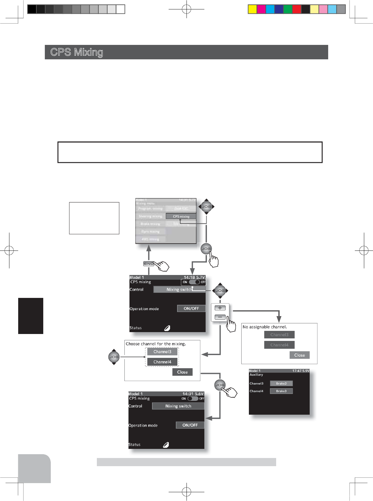
Mixing menu screen
or
Pres
s
Pres
s
Pu h
Pres
s
Pres
s
Pu
h
92
Function
CPS Mixing
CPS mixing
ON
When CPS mixing is set,
CPS ON/OFF is displayed
in a pop-up window on the
home screen.
This function controls the Futaba CPS-1 channel power switch.
Normally, when using the CPS-1 unit to light the vehicle dress-up and other illumination
(LED) the CPS-1 unit with LED connected is connected to a vacant switch channel and the
LEDs are turned on and off by switch while the vehicle is running. However, when the CPS
PL[LQJIXQFWLRQLVXVHGWKH/('FDQEHWXUQHGRQDQGRIIDQGÀDVKHGLQVWHSZLWKVWHHULQJ
DQGWKURWWOHRSHUDWLRQDVZHOODVEHLQJWXUQHGRQDQGRIIE\VZLWFK7KHÀDVKLQJVSHHGF\FOH
can also be set.
)RULQVWDQFHWKH/('FDQEHÀDVKHGDVDEUDNHOLJKWE\WKURWWOHEUDNHVLGHRSHUDWLRQ
CPS Mixing
The mixing function is assigned to CH3 and CH4. Channels used by other mixing can-
QRWEHXVHG:KHQWKHQXPEHURIFKDQQHOVLVLQVXI¿FLHQWFDQFHOWKHRWKHUPL[LQJ
The mixing used can be confirmed on
the Auxility screen. (p.155)
When CPS mixing is set to
"ON", the CPS-1 used chan-
nel setup screen is displayed.
CPS mixing screen from mixing menu screen (p.79)
Channel is selected by
(JOG) button operation.
When the gain is switched by
a switch, a pop-up window
appears on the home screen
to announce the gain.
4PX-Eng-08-Function-66-103.indd 92 2014/07/18 17:20:38
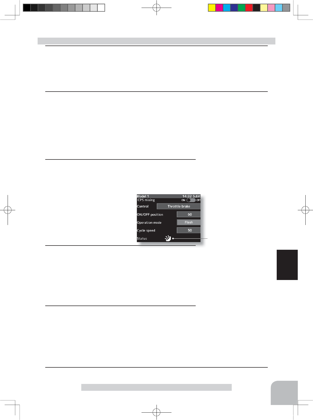
Adjustment buttons
- Use the (+) and (-) buttons to
make adjustments.
- Return to the initial value by
pressing the (+) and (-) buttons
simultaneously (approx. 1 sec).
On/OFF position
5 ~ 95
Initial value:50
Adjustment buttons
- Use the (+) and (-) buttons to
make adjustments.
- Return to the initial value by
pressing the (+) and (-) buttons
simultaneously (approx. 1 sec).
Cycle speed
1 ~ 100
Initial value:50
Setting buttons
- Use the (+) and (-) buttons to
make adjustments.
Operation mode
ON/OFF, Flash
93
Function
CPS Mixing
(Preparation)
- Refer to the left page and set the function to ON and set the mixing channel.
- CPS-1 connects to the receiver channel assigned to CPS mixing.
- When the LEDs are turned on and off by switch, use the function select switch function (P.99)
to set the switch to be used.
1(Control system setup)
Operate the (JOG) button up and down and select the setting item "Control".
Press the (+) or (-) button and select the function.
"Mixing Switch" : ON/OFF by switch set at the 3rd or 4th CH
"Steering neutral" : ON at steering neutral
"Steering endpoint" : ON at both sides of steering
"Throttle neutral" : ON at throttle neutral
"Throttle forward" : ON at throttle forward side
"Throttle brake" : ON at throttle back (brake) side
"
Throttle neutral & brake
" : ON at throttle neutral and back (brake) sides
CPS-1 mixing adjustment
2 (ON/OFF switching position selection)
Operate the (JOG) button up and down and select the set-
ting item "ON/OFF position".
Press the (+) or (-) button and select the ON/OFF position.
Since the ON/OFF state is dis-
played at the right side of the
setting item "Status", setting can
be confirmed while operating the
function to be controlled (for ex-
ample, throttle).
3 (Operation mode setup)
Operate the (JOG) button up and down and select the set-
ting item "Operation mode ".
Press the (+) or (-) button and select the type of LED lighting.
Normal ON/Off type or flashing can be selected.
"ON/OFF" : Normal ON/OFF type
"Flash" : Flashing display
4 (Flashing cycle setting)
When flashing type "Flash" was selected at the setting item
"Operation mode" the flashing speed (cycle) can be set.
Operate the (JOG) button up and down and select the set-
ting item "Cycle speed".
Press the (+) or (-) button and select the flashing speed (cycle
speed).
*Shows the ON/OFF state
5When ending setting, return to the Mixing menu screen by pressing the (END) button.
4PX-Eng-08-Function-66-103.indd 93 2014/07/18 17:20:39
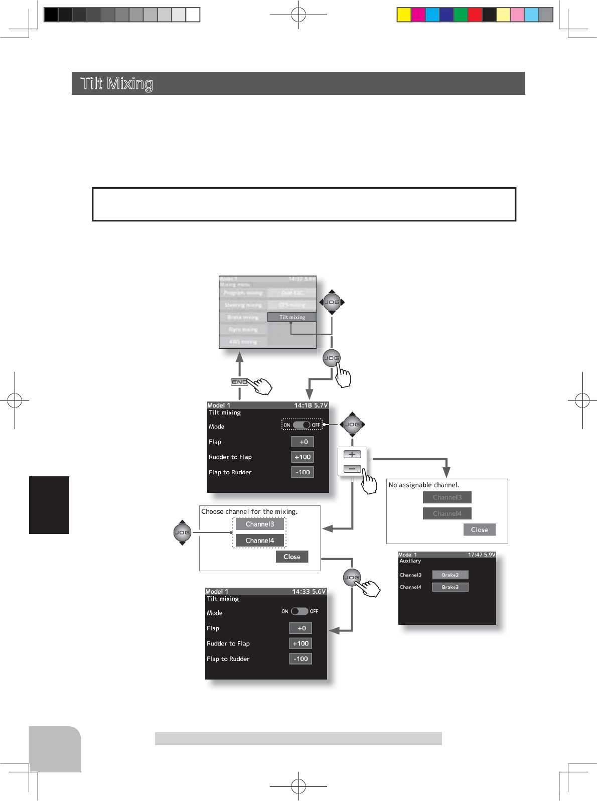
When tilt mixing is set to
"ON", the flaps channel setup
screen is displayed.
When tilt mixing is set to
"ON", the flaps channel setup
screen is displayed.
or
Mixing menu screen
Pres
s
Pres
s
Pu h
Pres
s
Pu h
Pres
s
94
Function
Tilt Mixing
The mixing function is assigned to CH3 and CH4. Channels used by other mixing can-
QRWEHXVHG:KHQWKHQXPEHURIFKDQQHOVLVLQVXI¿FLHQWFDQFHOWKHRWKHUPL[LQJ
Tilt mixing uses an outboard engine and applies bidirectional mixing from rudder (steering)
WRÀDSDQGIURPÀDSWRUXGGHUVRWKDWZLWKDERDWUXGGHURSHUDWLRQDQGWLOWPL[LQJRSHUD-
tion can be performed by 2 servos.
7LOWPL[LQJFDQEHSHUIRUPHGE\UXGGHURSHUDWLRQE\VWHHULQJZKHHODQGÀDSFKDQQHO
Tilt Mixing (Steering Throttle system)
The mixing used can be confirmed on
the Auxility screen. (p.155)
When channels 3 and 4 are used
by other mixing, the message
"No assignable channel" is dis-
played.
Tilt mixing screen from mixing menu screen (p.79)
Channel is selected by
(JOG) button operation.
4PX-Eng-08-Function-66-103.indd 94 2014/07/18 17:20:39
95
Function
Steering end point function, curve function, speed function, or D/R function setup also
HIIHFWVÀDSFKDQQHORSHUDWLRQ+RZHYHUHYHQLIVHWVWHHULQJUHYHUVHIXQFWLRQVHWXSGRHV
QRWUHYHUVHWKHÀDSFKDQQHO
Effect of the set value of other functions on tilt mixing
Tilt Mixing
(Preparation)
- Use the function select dial function to select the flap channel
operation dial. (p.101)
1(Function ON/OFF)
Refer to the left page and turn on the function and set the
mixing channel (flap).
2(Flap rate check and adjustment)
Select the setting item "Flap" by (JOG) button up or down
operation, and adjust the flaps by (+) or (-) operation.
3(Rudder to Flap mixing amount adjustment)
Select setup item "Rudder to Flap" by (JOG) button up or
down operation, and use the (+) and (-) buttons to adjust the
mixing amount.
"+" :Operate in same direction as steering
"-" :Operate in opposite direction of steering
4(Flap to Rudder mixing amount adjustment)
Select setup item "Flap to Rudder" by (JOG) button up or
down operation, and use the (+) and (-) buttons to adjust the
mixing amount.
"+" :Operate in same direction as channel 3
"-" :Operate in opposite direction of channel 3
Tilt mixing adjustment
The mixing rate amount can be controlled with digital dial or digital trim, using the
function select dial function. (p.101)
Dial / Trim Setting
Rudder to Flap channel side : +100%
Flap channel to Rudder side : -100%
Slave channel output (Initial value)
Setting buttons
- Use the (+) and (-) buttons to
make adjustments.
Function ON/OFF (Mode)
ON, OFF
Adjustment buttons
- Use the (+) and (-) buttons to
make adjustments.
- Return to the initial value by
pressing the (+) and (-) buttons
simultaneously (approx. 1 sec).
Flap rate
-100~+100
Initial value: 0
Mixing amount (Rudder to Flap)
-100~+100
Initial value: +100
Mixing amount (Rudder to Flap)
-100~+100
Initial value: +100
5When ending setting, return to the Mixing menu screen by pressing the (END) button.
4PX-Eng-08-Function-66-103.indd 95 2014/07/18 17:20:39
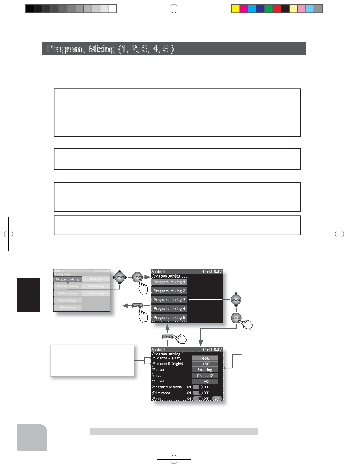
Program mixing 1 5 to be
used is selected by (JOG)
button.
Pres
s
Pres
s
Pu h
Pres
s
Pu h
Pres
s
96
Function
Program, Mixing
When trigger ratio (p.66) was set to 100:0, brake operation stops. When the master chan-
nel (MST) was set to throttle, mixing operates only at the "Rate A (forward)" side. It does
not operate at the "Rate B (brake)" side.
When trigger ratio was set to 100:0
Mixing menu screen
Other mixing functions are assigned to CH3 or CH4. Program mixing can use CH3 or
CH4 regardless of the other mixing functions. However, be careful because they interact.
These setup items are different depend-
ing on the master channel.
Mix rate A : left, fowrward, up
Mix rate B : right, breke, down
These functions allow you to apply mixing between the steering, throttle, channel 3 and
channel 4.
-When the steering or throttle channel is the master channel (channel that applies mix-
ing), trim data can be added. (Trim mode)
- The mixing mode selection. (Master mixing mode)
- The master channel mixing center point (point at which the direction changes) can be
offset. (Offset function)
Additional Functions
The movement of the master channel side will be added to the movement of the slave
channel side.
Movement of the slave channel side
Program, Mixing (1, 2, 3, 4, 5 ) (All channels)
Setup items
Mix rate A
Mix rate B
Master
Slave
Offset
Master mix mode
Trim mode
Mode (ON/OFF)
Program. mixing screen from mixing menu screen (p.79)
4PX-Eng-08-Function-66-103.indd 96 2014/07/18 17:20:40
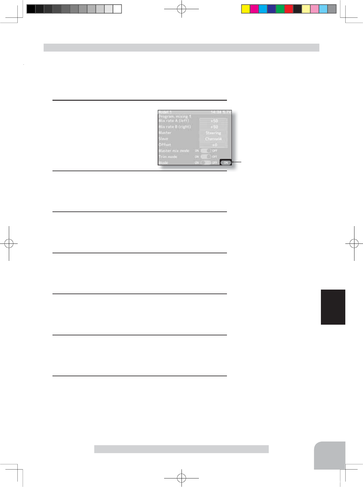
When mixing is active, ON
is displayed.
97
Function
Program, Mixing
Program mixing adjustment
Switch
Program mixing 1-5
Setup item selection
- Select by (JOG) button up or
down operation.
(Preparation)
- Use the function select switch function (page 99) to select the
switch. (as desired)
- Select the "Program mixing" by (JOG) button up or down op-
eration, and select the 1 to 5 by pressing the (JOG) button.
1 (Mixing function ON/OFF)
Select the setting item "Mode"
by (JOG) button up or down op-
eration. Press the (+) or (-) but-
ton and set the function to the
"ON" state.
"OFF" :Function OFF
"ON" :Function ON
2(Master channel)
Select setup item "Master" by (JOG) button up or down op-
eration, and select the master channel by pressing the (+) or
(-) button.
3(Slave channel)
Select setup item "Slave" by (JOG) button up or down opera-
tion, and select the slave channel by pressing the (+) or (-)
button.
4 (Left, forward or up side mixing amount adjustment)
Select the setting item "left", "forward ", or "up" by (JOG) but-
ton up or down operation. Use the (+) or (-) button and adjust
the right, brake, or down side mixing amount.
5 (Right, brake or down side mixing amount adjustment)
Select the setting item "right", "brake", or "down" bby (JOG)
button up or down operation. Use the (+) or (-) button and
adjust the right, brake, or down side mixing amount.
6(Offset amount setup)
Select setup item "Offset" bby (JOG) button up or down op-
eration, and use the (+) and (-) button to adjust the offset
amount.
7(Mixing mode setup)
Select setup item "Master mix mode" bby (JOG) button up or
down operation, and use the (+) and (-) button to adjust the
offset amount.right operation, and use the (+) or (-) button to
select the mixing mode.
"OFF" :Mixing proportional to master channel operation.
"ON" :Mixing by master channel another function considered.
Setting buttons
- Use the (+) and (-) buttons to
make adjustments.
Function ON/OFF (Mode)
ON, OFF
Setting buttons
- Use the (+) and (-) buttons to
make adjustments.
Master mix mode
ON, OFF
Setting buttons
- Use the (+) and (-) buttons to
make adjustments.
Channel selection (Master)
Steering, Throttle
Channel3, Channel4
Channel selection (Slave)
Channel1, Channel2
Channel3, Channel4
Adjustment buttons
- Use the (+) and (-) buttons to
make adjustments.
- Return to the initial value by
pressing the (+) and (-) buttons
simultaneously (approx. 1 sec).
Mixing amount
-100~0~+100
Initial value: +50
Adjustment buttons
- Use the (+) and (-) buttons to
make adjustments.
- Return to the initial value by
pressing the (+) and (-) buttons
simultaneously (approx. 1 sec).
Offset amount
-100~0~+100
Initial value: 0
4PX-Eng-08-Function-66-103.indd 97 2014/07/18 17:20:40
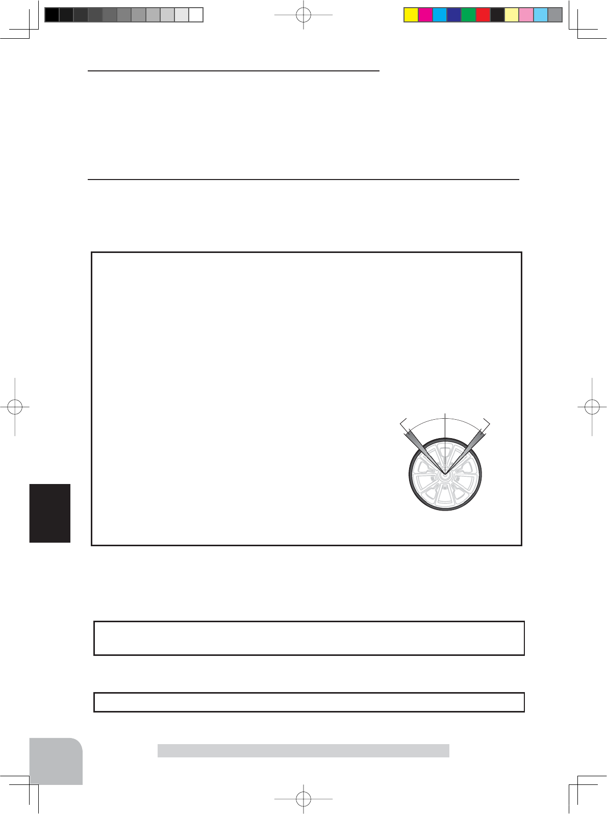
98
Function
Program, Mixing
A
A
Full rightFull left
A :Zone over which servo
does not operate
:KHQWKHVWHHULQJVHUYRWUDYHOLVLQVXI¿FLHQWHYHQZKHQ'5LVDQG(QGSRLQWLV
140%, programmable mixing can be used to increase the travel somewhat.
(Reference data)
- Program nixing(1 - 5)->ON
- Master channel -> Steering Mixing is applied from steering
- Slave channel ->Steering Mixing is applied to steering and the travel is increased.
- Mix rate A (left) -> 10% [When subtrim is centered (0%)]
- Mix rate B (right) -> 10% [When subtrim is centered (0%)]
- Offset -> 0% / - Master mix mode -> ON / - Trim mode -> OFF
However, the operating range of the servo is exceeded
even if a large value is input at "Mix rate A (left)" and
"Mix rate B (right)" and a zone over which the servo
does not operate even when the wheel is moved to the
left or right is created. A zone over which the servo does
not operate is also generated at the moving side when
the subtrim is moved to the left and right. Therefore, set
the "Mix rate A (left)" and "Mix rate B (right)" value by
checking servo operation.
When Steering and Throttle Travel is Insufficient
The mixing amount can be adjusted by using the function dial function. (p.101)
Dial / Trim Setting
Select the program mixing function ON/OFF switch with the function select switch
function. ( p.99)
Switch Setting
8(Trim mode setup)
Select setup item "Trim mode" by (JOG) button up, down,
left, or right operation, and use the (+) or (-) button to select
the mixing mode.
"OFF" :Trim is added.
"ON" :Trim is removed.
Setting buttons
- Use the (+) and (-) buttons to
make adjustments.
Trim mode
ON, OFF
9When ending setting, return to the Mixing menu screen by pressing the (END) button.
4PX-Eng-08-Function-66-103.indd 98 2014/07/18 17:20:40
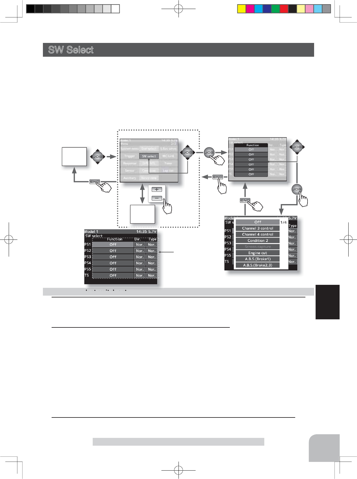
HOME
screen
or
MENU
1screen
MENU 2 screen
99
Function
SW Select
1 (Select switch selection)
Select "Function" of the switch you want to set by (JOG) button up, down, left, or right op-
eration, and press the (JOG) switch.
Function select switch setup
2 (Function setup)
A function list is displayed. Select the desired function by (JOG)
button up or down operation, and press the (JOG) button.
(Changing the operation direction)
Select "Dir" of the switch you want to set by (JOG) button up, down,
left, or right operation, and switch the direction by (+) or (-) button.
(Changing the type of operation)
Select "Type" of the switch you want to set by (JOG) button up,
down, left, or right operation and switch the type by (+) or (-) button.
3When ending setting, return to the menu screen by pressing the (END) button.
SW Select
This function allows selection of the function to be performed by the switches
(PS1, PS2, PS3, PS4, PS5, throttle trigger) and setting of the direction, etc. of operation.
-The table in the next page lists the functions that can be assigned to each push switch.
-All switches can be made alternating operations (ON/OFF switched each time SW pressed).
(NOR/ALT)
-The ON/OFF direction can be reversed. The reverse select function always starts from the ON
state. However, the trigger switch is different, depending on the position. (NOR/REV)
Setup buttons
- Use the (+) and (-) buttons to
make adjustments.
- Press the (+) and (-) buttons
simultaneously (approx. 1 sec)
to return to the initial screen.
Initial value:
"OFF", "Nor", "Nor"
Setup switch selection
- Select by (JOG) button up,
down operation.
Setup items
Function
Dir
Type
Pres
s
Pres
s
Pres
s
Pu h
Pres
s
Pu h
Pres
s
Pu
h
Pres
s
4PX-Eng-08-Function-66-103.indd 99 2014/07/18 17:20:41
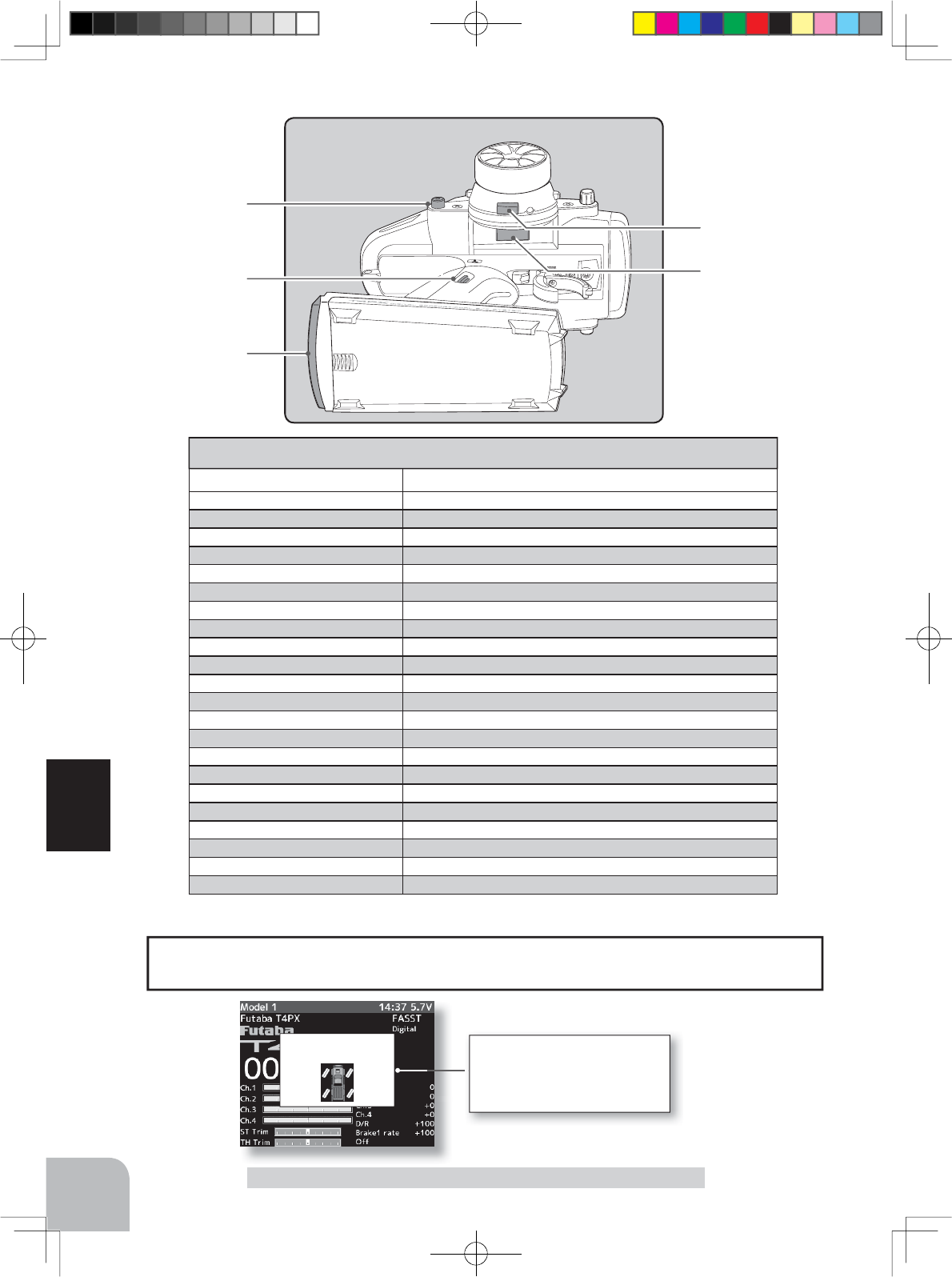
PS1
PS5
PS2
PS4
PS3
100
Function
Abbreviation used on setup screen
Function name, etc
Channel 3 control
Operation of channel 3
Channel 4 control Operation of channel 4
Condition 2 2nd condition function ON/OFF
Screen capture The screen capture is preserved on the microSD card.
Engine cut Engine cut
A.B.S.(Brake1) A.B.S function brake1(2CH)ON/OFF
A.B.S.(Brake2,3) A.B.S function brake2,3(3CH/4CH)ON/OFF
Neutral brake Neutral brake function ON/OFF
Idle up Idle up function ON/OFF
Program mixing(1-5) Program mixing(1-5) function ON/OFF
4WS mixing 4WS mixing function ON/OFF & type select
Dual ESC (Rear)Dual ESC mixing (Rear Drive mode)
Dual ESC (4WD)Dual ESC mixing (4WD mode)
Dual ESC (Front)Dual ESC mixing (Front Drive mode)
Gyro mixing Switching GYRO mode (Switch of Gain1 and 2)
CPS mixing CPS up function ON/OFF
Brake Steering mixing (Brake function ON/OFF)
Timer start
Timer function start /stop
Timer reset Timer function reset
Timer reset
Telemetry voice guide ON/OFF
Timer reset
Telemetry data logging ON/OFF
OFF
Not used
Set table functions (PS1/PS2/PS3/PS4/PS5) & Trigger switch (TS)
SW Select
Example :4WS Mixing
4WSmixing
Type 3
When the set SW is operated
in the HOME screen state, the
4WS mode is displayed here for
about 2 seconds.
When push switch is operated in the HOME screen state, the state of the function is dis-
played in the center for about one or two seconds.
The HOME screen display
4PX-Eng-08-Function-66-103.indd 100 2014/07/18 17:20:41
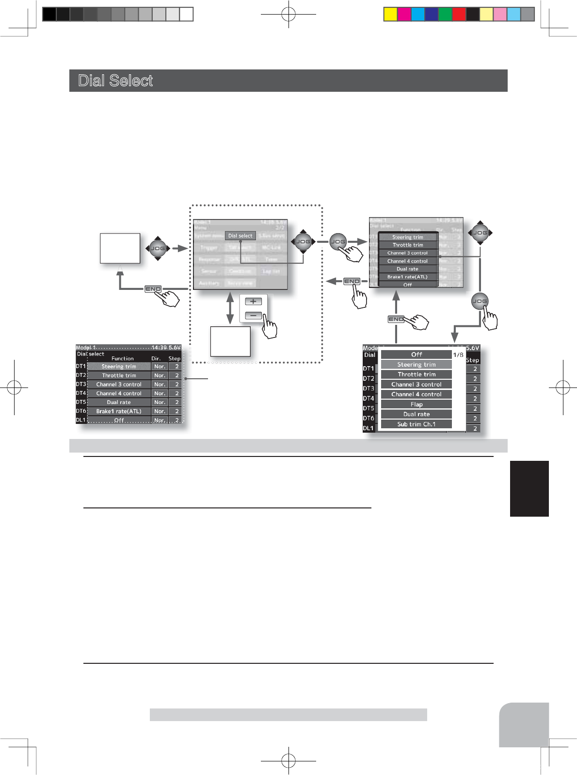
or
MENU
1screen
MENU 2 screen
Pus
h
HOME
screen
101
Function
Dial Select
Function select dial setup
1 (Select dial selection)
Select "Function" of the trim or dial you want to set by (JOG) button up, down, left, or right
operation, and press the (JOG) button. Setup item selection
- Select by (JOG) button up,
down, left or right operation
Adjustment buttons
- Use the (+) and (-) buttons to
make adjustments.
- Press the (+) and (-) buttons
simultaneously (approx. 1 sec)
to return to the initial screen.
Dial Select
This function allows selection of the function performed by the digital dial DL1 and digital
trimmers (DT1 ~ DT6), step amount adjustment, and operating direction reversal.
- The table in the next page lists the functions that can be assigned to each dial and digital trim-
mer. The assigned function is also displayed on the opening screen together with the current
adjustment value. They are displayed in DL1and DT1 ~ DT6 order, from top to bottom.
- The step amount can be adjusted. The table in the following page shows the relationship be-
tween set value and step amount.
- The operation direction can be reversed. (NOR/REV)
Setup items
Function
Dir
Step
2 (Function setup)
A function list is displayed. Select the desired function by (JOG)
button up or down operation, and press the (JOG) button.
(Changing the operation direction)
Select "Direction" of the switch you want to set by (JOG) button
up, down, left, or right operation and switch the direction by (+) or (-) button.
(Changing the operation step amount)
Select "Step" of the switch you want to set by (JOG) button up, down, left or right operation,
and switch the type by (+) or (-) button.
- For the relationship between set value and step amount, see the preceding page
3When ending setting, return to the menu screen by pressing the (END) button.
Pres
s
Pres
s
Pres
s
Pu h
Pres
s
Pu h
Pres
s
4PX-Eng-08-Function-66-103.indd 101 2014/07/18 17:20:42
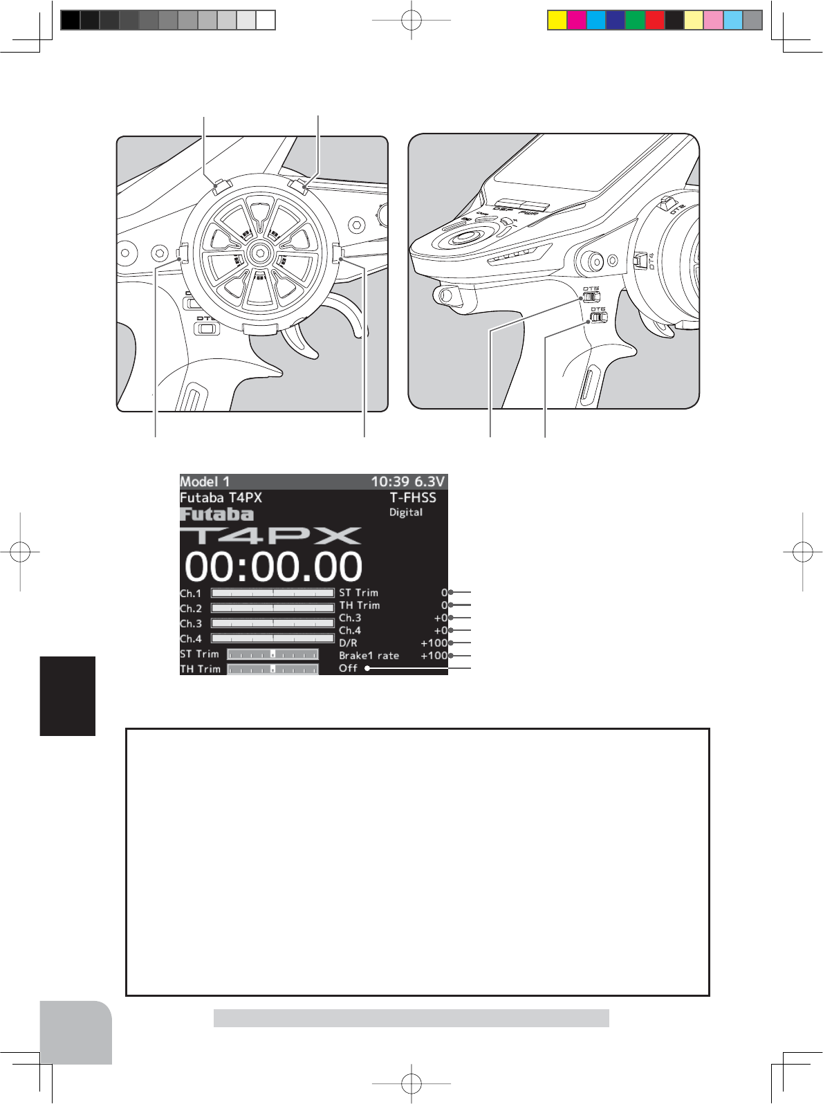
DT1
DT2
DT3
DT4
DT5
DT6
DL1
DT5 DT6
DT1
DT2
DT4 DT3
102
Function
Dial Select
Initial value:
DT1 :Steering trim
DT2 :Throttle trim
DT3 :Channel3 control
DT4 :Channel4 control
DT5 :Dual rate
DT6 :Brake1 rate(ATL)
DL1 :OFF
Dir:Nor/ Step:2
(Setting range: 1, 2, 5, 10, 20, 30, 40, 50, 100, 200)
-Steering trim/throttle trim
When set to the minimum "1", the total trim operating width is 200 clicks. For "100", the
total operating width is 2 clicks and for 2PS, the total operating width is 1 click.
-Rate, etc. setting
This is the % value which is operated by 1 click relative to the set value of each rate.
Since the total operating width of functions having a rate of -100~0~+100 is 200%, when
set to "100", the total operating width is 2 clicks. Since the total operating width of func-
tions with a 0~100 rate is 100%, "100" and "200" are operated by 1 click.
-Channel 3/4
When set to the minimum "1", the total operating width of channel 3 is 200 clicks. For
"100", the total operating with is 2 clicks and "200" is operated by 1 click.
Relationship between set value and step amount
4PX-Eng-08-Function-66-103.indd 102 2014/07/18 17:20:42
Abbreviation used on setup
screen
Abbreviation displayed on
opening screen
Function name, etc
Steering trim ST Trim Steering trim
Throttle trim TH Trim Throttle trim
Channel 3 control Ch.3 Channel 3 control
Channel 4 control Ch.4 Channel 4 control
Dual rate D/R Dual rate function
Sub trim Ch1~4 Sub trim Ch1~4 Sub trim Ch1~4
Acceleration(forward) Accel, forward Throttle acceleration (Forward side)
Acceleration(brake1) Accel, brake1 Throttle acceleration (Brake1 side)
Acceleration(brake2) Accel, brake2 Throttle acceleration (Brake2 side)
Acceleration(brake3) Accel, brake Throttle acceleration (Brake3 side)
Steering curve ST curve Steering curve (EXP) rate
Throttle curve TH curve Throttle curve (EXP) (Forward side)
Steering speed(turn) ST speed(turn) Steering speed (Turn side)
Steering speed(return) ST speed(return) Steering speed (Return side)
ABS(return brake1) ABS1 ret. Brake1 A.B.S. function (Return amount)
ABS(delay brake1) ABS1 delay Brake1 A.B.S. function (Delay amount)
ABS(cycle brake1) ABS1 cycle Brake1 A.B.S. function (cycle speed)
ABS(return brake2) ABS2 ret. Brake2 A.B.S. function (Return amount)
ABS(delay brake2) ABS2 delay Brake2 A.B.S. function (Delay amount)
ABS(cycle brake2) ABS2 cycle Brake2 A.B.S. function (cycle speed)
ABS(return brake3) ABS3 ret. Brake3 A.B.S. function (Return amount)
ABS(delay brake3) ABS3 delay Brake3 A.B.S. function (Delay amount)
ABS(cycle brake3) ABS3 cycle Brake3 A.B.S. function (cycle speed)
Brake1 rate(ATL) Brake1 rate Brake1 rate (ATL)
Brake EXP(brake1) Brake1 EXP Throttle EXP (Brake1 side)
Brake delay(brake1) Brake1 deray Brake mixing: Brake1 delay
Brake2 rate Brake2 rate Brake mixing: Brake2 rate function
Brake EXP(brake2) Brake2 EXP Brake mixing: Throttle EXP (Brake2 side)
Brake delay(brake2) Brake2 deray Brake mixing: Brake2 delay
Brake3 rate Brake3 rate Brake mixing: Brake3 rate function
Brake EXP(brake3) Brake3 EXP Brake mixing: Throttle EXP (Brake3 side)
Brake delay(brake3) Brake3 deray Brake mixing: Brake3 delay
Brake2,3 rate Brake2,3 rate Brake mixing: Brake2,3 rate function
Tilt mixing (RUD FLP) Tilt R to F Tilt mixing: rudder to flap rate
Tilt mixing (FLP RUD) Tilt F to R Tilt mixing: flap to rudder rate
Idle up Idle up Idle up function rate
Prog. mixing 1~5 A P.mix 1~5 A Program mixing: rate A side (Left/Forward/Up sides)
Prog. mixing 1~5 B P.mix 1~5 B Program mixing: rate B side (Right/Brake/Down sides)
4WS rear rate 4WS rate 4WS mixing: (rear steering rate)
Dual ESC Dual ESC Dual ESC mixing (Drive mode select)
Dual ESC ratio ESC ratio Dual ESC mixing: drive ratio (front & rear)
Gyro Gain Gyro Gyro mixing: (Gain rate)
Ackermann rate Ackermann Ackermann mixing: (ackermann rate)
Steering response ST response Steering response adjustment
Throttle response TH response Throttle response adjustment
Flap Flap Tilt mixing: flap rate
OFF Off Not used
Set table functions (DL1/ DT1, DT2, DT3, DT4, DT5, DT6)
103
Function
Dial Select
4PX-Eng-08-Function-66-103.indd 103 2014/07/18 17:20:42
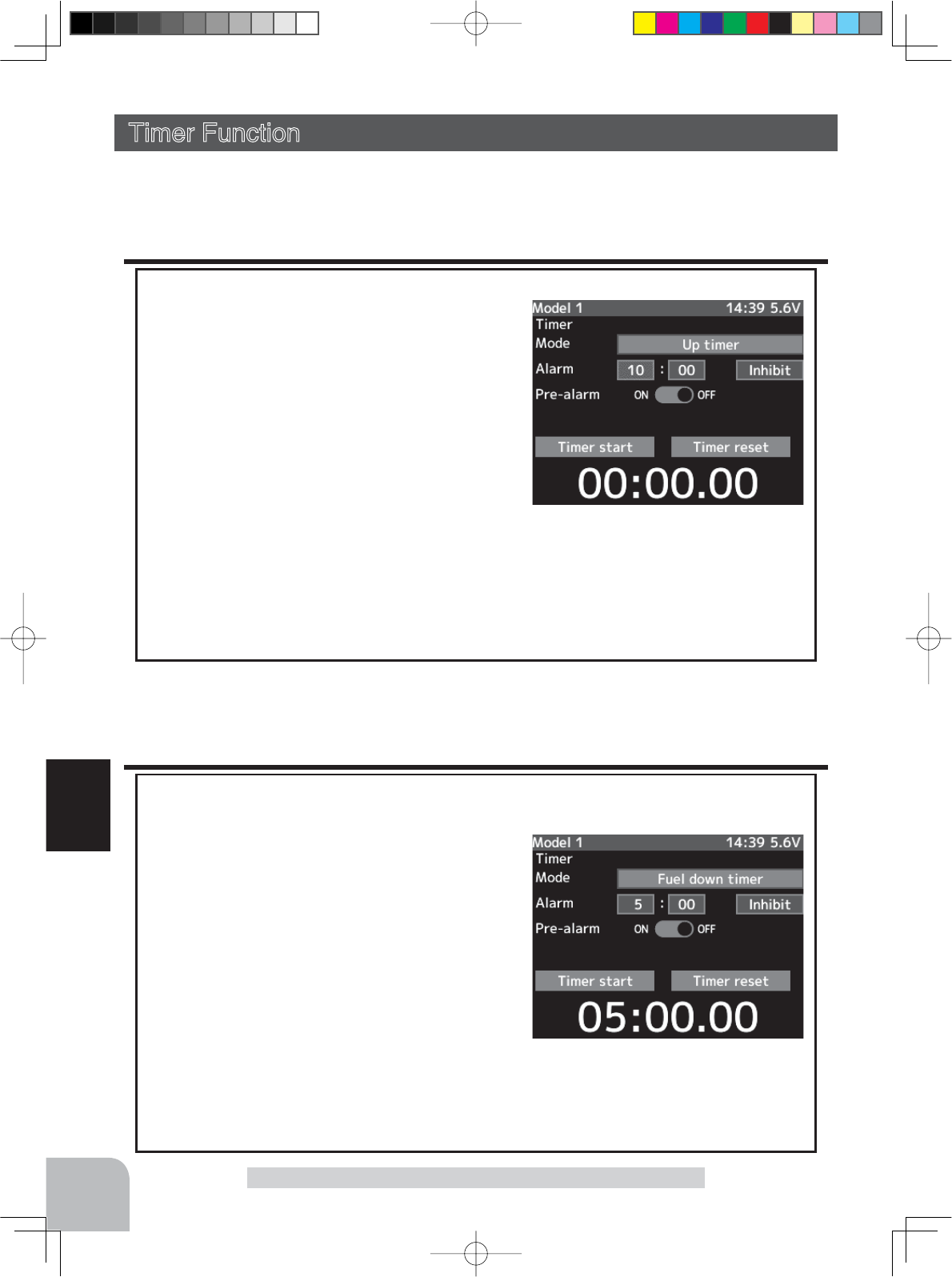
104
Function
Timer Function
Timer Function
Use the timer by selecting one of the four timers Up timer, Fuel down timer, Lap timer and
Lap navigate timer.
Up timer function
- The Up timer can be used to count the time between start and stop, etc.
- The timer repeatedly starts and stops each time
the switch is operated and accumulates the time
between each start and stop. (When the count
reaches 99 minutes 59 seconds, it returns to 00
minutes 00 seconds and repeats the count.)
- The first start operation can be linked to the
throttle trigger.
- An alarm sound can be set. The passage of time
is announced by sounding of a buzzer (beeps)
each minute after starting.
- Alarm :Generates a beep at the set time (minutes).
- Prealarm :Alarm advance announcement sound. Sounding begins 10 seconds before the set alarm
time.
- After starting, the timer is enabled and can be stopped by switch even when the display
switches to another screen.
Fuel down timer function
The fuel down timer is used primarily to check the refueling time of gasoline engine cars.
(The remaining time is displayed.)
- Each time the switch is pressed, the timer is
restarted and the set time is counted down. The
start time becomes the alarm set time. (When
counted down to 00 minutes 00 seconds, the timer
becomes an Up timer.)
- The fuel down timer can be initially started by
throttle trigger.
- An audible alarm can be set. In addition, the
passing of time is indicated by sounding of a
buzzer each minute after starting.
- Alarm :Buzzer sounds at the set time (minute).
- Prealarm :Alarm advance announcement sound. Sounding begins 10 seconds before the set alarm
time.
- After starting, the timer continues to count even if the LCD switches to another screen.
4PX-Eng-08-Function-104-156.indd 104 2014/07/18 17:36:07
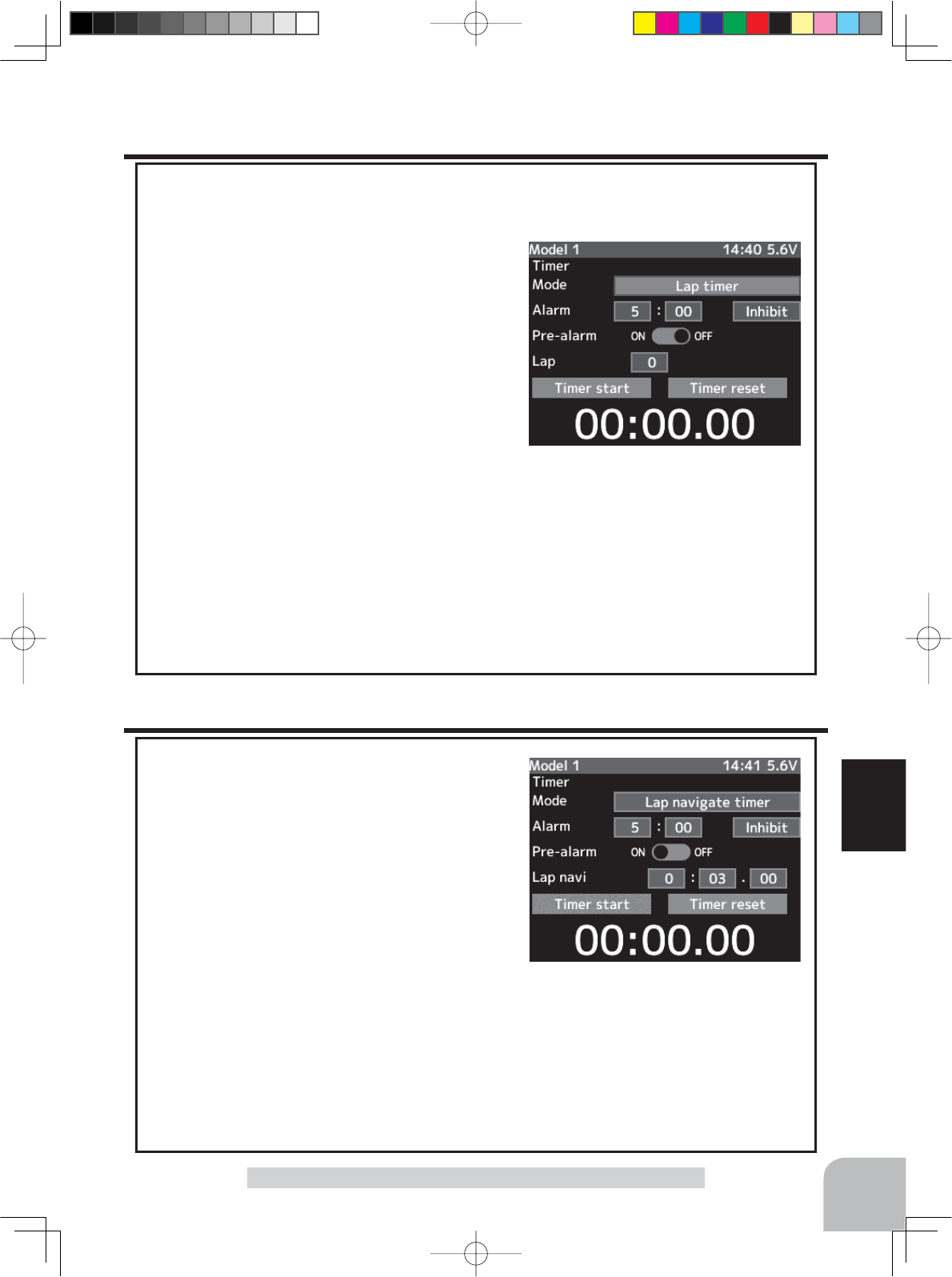
105
Function
Timer Function
Lap timer function
Lap timer function
- The Lap timer can memorize each lap time of each switch operation. (60 laps)
- The race time can be set. Switch operation after
the set time by alarm has elapsed automatically
stops the timer. Prealarm can also be set. The pas-
sage of time is announced by sounding of a buzzer
(beeps) each minute after starting.
-Alarm :Generates a beep at the set time.
Prealarm :Starts sounding the set time (second) be-
fore the alarm. (beeps)
7KH ¿UVWVWDUW RSHUDWLRQFDQ EH OLQNHGZLWKWKH
throttle trigger.
(Lap timer operation)
- When lap timer is selected, the number of laps (LAP) and the lap memory No. (No.) and
current lap time (TIME) are displayed on the setup screen.
*LAP: Counted up each time the switch is pressed after starting. After the switch was pressed, the
numbers pause for 3 seconds. To prevent erroneous counting, switch operation is not accepted during
this time
*Lap memory: The lamp memory saves the lap times of 60 laps.
*The lap time data stored in the lap memory can be checked at the lap list (P111) screen.
Lap navigate timer function
Lap navigate timer function
7KLVIXQFWLRQVRXQGVDEX]]HUDWD¿[HGLQWHUYDO
after the timer starts. Since only the buzzer can be
restarted when the switch is pressed during timer
operation, this function can be used as the train-
ing run, etc. target time. (Lap navigation alarm)
The passage of time is announced by sounding of
a buzzer (beeps) every minute after starting.
7KH ¿UVWVWDUW RSHUDWLRQFDQ EH OLQNHGZLWKWKH
throttle trigger.
- The alarm sounds (alarm/prealarm) can be set
VHSDUDWHO\IURPWKH¿[HGLQWHUYDOEX]]HU
- Alarm :Generates a beep at the set time (minutes).
- Prealarm :Alarm advance announcement sound. Sounding begins 10 seconds before the set alarm
time.
- After starting, the timer is enabled and can be stopped by switch even when
the display switches to another screen.
4PX-Eng-08-Function-104-156.indd 105 2014/07/18 17:36:07
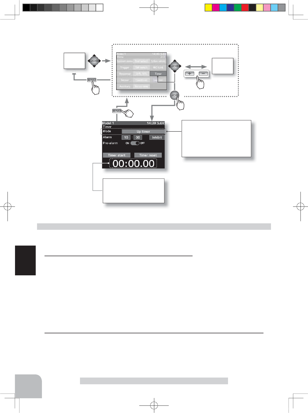
HOME
screen MENU 1
screen
or
MENU 2 screen
106
Function
Timer Function
Timer selection
First, select the type of timer at
the "Mode" item. The setup screen
varies depending on the type of
timer. This figure shows the Up
timer setup screen.
(Preparation)
Assign the "Timer start" switch using the function select switch
(p.99). When resetting by switch, assign "Lap reset" also.
1 (Racing timer type selection)
Select the setting item "Mode" by (JOG) button up, down,
left, or right operation. Press the (+) or (-) button and set the
racing timer type.
Timer selection (TYPE)
Up timer
Fuel down timer
Lap timer
Lap navigate timer
Racing timer type selection
Time display
Minute display (m)
Second display (s)
1/100 second display
Setup item selection
- Select by (JOG) button up,
down, left or right operation.
Adjustment buttons
- Use the (+) and (-) buttons to
make adjustments.
2When ending setting, return to the menu screen by pressing the (END) button.
Pres
s
Pres
s
Pres
s
Pre
Pres
s
4PX-Eng-08-Function-104-156.indd 106 2014/07/18 17:36:08
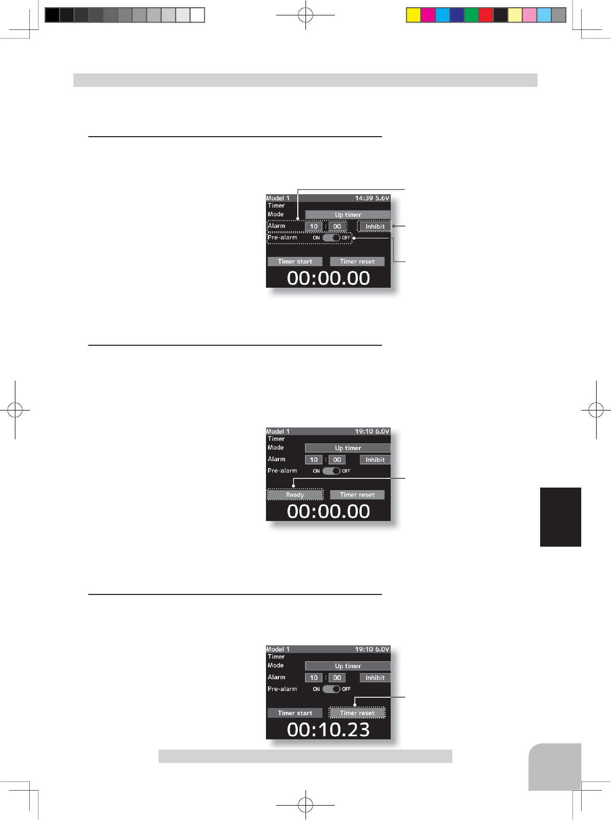
Adjustment buttons
- Use the (+) and (-) buttons to
make adjustments.
- Press the (+) and (-) buttons
simultaneously (approx. 1 sec)
to return to the initial screen.
Switches
Timer start :start / stop
Lap reset :stop / reset
Timer start/ reset
Alarm time
OFF, 1 ~ 99 m
Initial value: 5 m
Grip vibrator type
Inhibit(Off), Type1,2,3
Initial value: Inhibit
Prealarm time
OFF, ON
Initial value: OFF
Status display
Ready:
T
hrottle trigger operation wait
Timer start:
Timer running/ Timer stopped
107
Function
Timer Function
(Preparation)
Select the setting item "Mode" by (JOG) button up or down
operation. Press the (+) or (-) button and select "Up timer".
1(Alarm time setting)
Select the setting item "Alarm" by (JOG) button up, down,
left, or right operation and set the alarm time with the (+) and
(-) buttons.
The setting item at the right side
of the alarm time is the alarm vi-
bration setting. Select one of the 3
patterns or inhibit (OFF) by (+) or
(-) button.
(Pre alarm time setting)
Select the setting item "Pre-alarm" by (JOG) button up,
down, left, or right operation, and set the pre alarm to the ac-
tive state by pressing the (+) or (-) button.
2(Timer start/stop operation)
When the switch ("Timer start") assigned by function select
switch function is pressed, the timer starts. Stop the timer
with the same switch ("Timer start") as start, or with the
switch assigned the "Lap reset" function.
- Linking only start to the throttle
trigger
Select the setting item "Timer
start" by (JOG) button up, down,
left, or right operation and press
the (+) and (-) buttons simultane-
ously for about 1 second. When
the set beeps and the status display switches from "Timer
start" to "Ready", the system enters the trigger operation
ready state. When the trigger is operated at the forward side,
the timer starts. (Status display "Timer start")
3(Timer reset operation)
When the switch ("Timer reset") assigned by function select
switch function is pressed, the timer is reset.
When a switch is not set, select
"Timer reset" by (JOG) button up
or down operation, and press the
(JOG) button. A beeping sound is
generated and the timer is reset.
Using the Up timer
4PX-Eng-08-Function-104-156.indd 107 2014/07/18 17:36:08
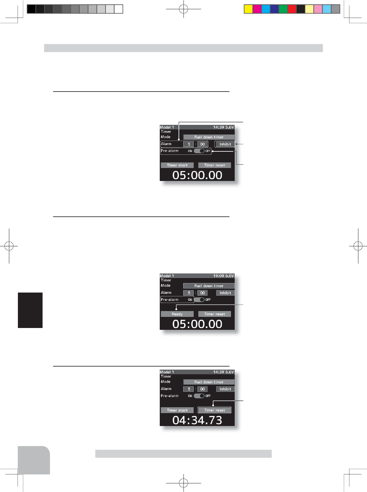
Adjustment buttons
- Use the (+) and (-) buttons to
make adjustments.
- Press the (+) and (-) buttons
simultaneously (approx. 1 sec)
to return to the initial screen.
Switches
Timer start :start / stop
Lap reset :stop / reset
Timer start/ reset
Alarm time
OFF, 1 ~ 99 m
Initial value: 5 m
Grip vibrator type
Inhibit(Off), Type1,2,3
Initial value: Inhibit
Prealarm time
OFF, ON
Initial value: OFF
Status display
Ready:
T
hrottle trigger operation wait
Timer start:
Timer running/ Timer stopped
108
Function
Timer Function
(Preparation)
Select the setting item "Mode" by (JOG) button up or down
operation. Press the (+) or (-) button and select "Fuel down
timer".
1(Alarm time setting)
Select the setting item "Alarm" by (JOG) button up, down,
left, or right operation and set the alarm time with the (+) and
(-) buttons.
The setting item at the right side
of the alarm time is the alarm vi-
bration setting. Select one of the 3
patterns or inhibit (OFF) by (+) or
(-) button.
(Pre alarm time setting)
Select the setting item "Pre-alarm" by (JOG) button up,
down, left, or right operation, and set the pre alarm to the ac-
tive state by pressing the (+) or (-) button.
2(Timer start/stop operation)
When the switch ("Timer start") assigned by function select
switch function is pressed, the timer starts. Stop the timer
with the same switch ("Timer start") as start, or with the
switch assigned the "Lap reset" function.
- Linking only start to the throttle trigger
Select the setting item "Timer
start" by (JOG) button up, down,
left, or right operation and press
the (+) and (-) buttons simultane-
ously for about 1 second. When
the set beeps and the status dis-
play switches from "Timer start" to
"Ready", the system enters the trigger operation ready state.
When the trigger is operated at the forward side, the timer
starts. (Status display "Timer start")
3(Timer reset operation)
When the switch ("Timer reset")
assigned by function select switch
function is pressed, the timer is
reset. When a switch is not set,
select "Timer reset" by (JOG) but-
ton up or down operation, and
press the (JOG) button. A beeping sound is generated and
the timer is reset.
Using the fuel down timer
4PX-Eng-08-Function-104-156.indd 108 2014/07/18 17:36:08
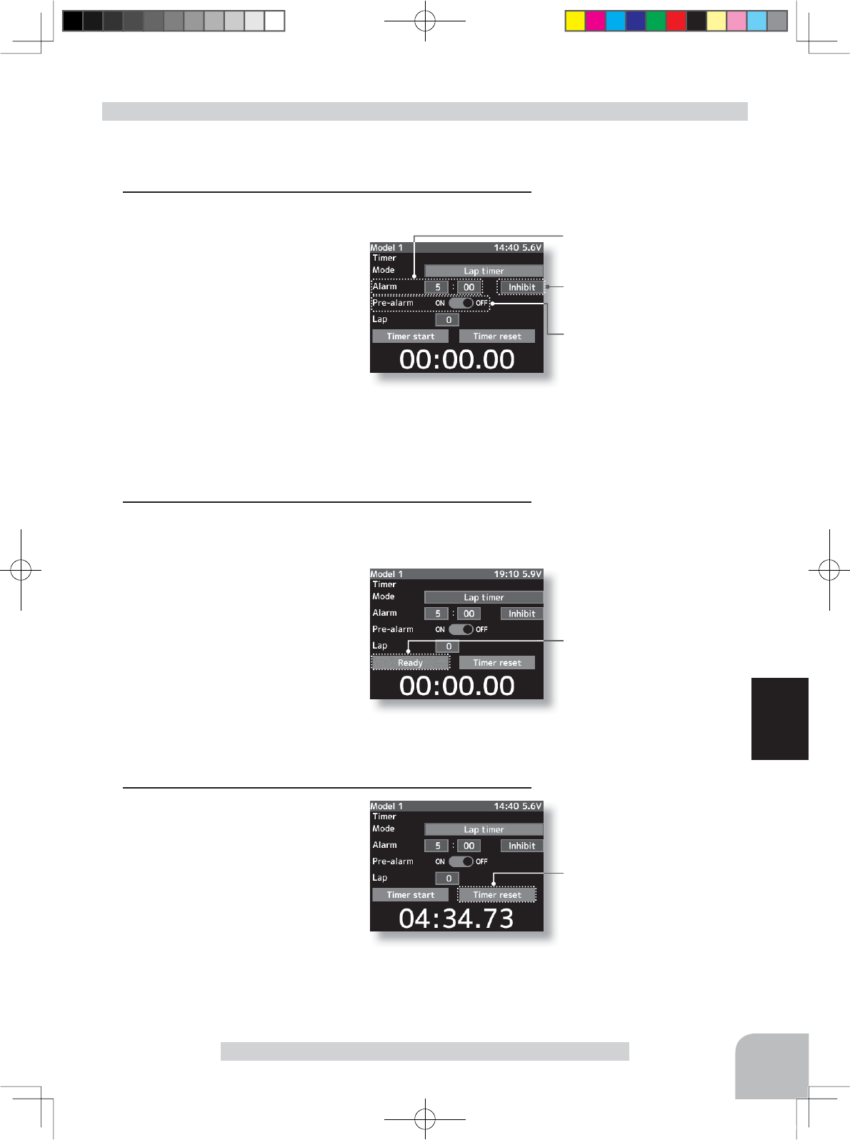
Alarm time
OFF, 1 ~ 99 m
Initial value: 5 m
Grip vibrator type
Inhibit(Off), Type1,2,3
Initial value: Inhibit
Prealarm time
OFF, ON
Initial value: OFF
Status display
Ready:
T
hrottle trigger operation wait
Timer start:
Timer running/ Timer stopped
Timer start/ reset
Will not start if the last lap timer is
not reset
109
Function
Timer Function
Adjustment buttons
- Use the (+) and (-) buttons to
make adjustments.
- Press the (+) and (-) buttons
simultaneously (approx. 1
sec) to return to the initial
screen.
Switches
Timer start :start / stop
Lap reset :stop / reset
(Preparation)
Select the setting item "Mode" by (JOG) button up or down
operation. Press the (+) or (-) button and select "Lap timer".
1(Alarm time setting)
Select the setting item "Alarm"
by (JOG) button up, down, left, or
right operation and set the alarm
time with the (+) and (-) buttons.
The setting item at the right side
of the alarm time is the alarm vi-
bration setting. Select one of the 3
patterns or inhibit (OFF) by (+) or
(-) button.
(Pre alarm time setting)
Select the setting item "Pre-alarm" by (JOG) button up,
down, left, or right operation, and set the pre alarm to the ac-
tive state by pressing the (+) or (-) button.
2(Timer start/lap count operation)
Perform the start and lap count operations with the switch
("Timer start") assigned by function select switch function.
- Linking only start to the throttle
trigger.
Select the setting item "
Timer start"
by (JOG) button up, down, left, or
right operation and press the (+)
and (-) buttons simultaneously for
about 1 second. The set beeps and
the timer display changes from "
Timer start
" to "
Ready
" and
the set enters the trigger operation ready state. (Status display
"
Timer star"
)
3(Timer stop/reset operation)
When the lap count switch or
"Timer reset" switch is pressed
after the time set by "Alarm" has
elapsed and the lap time, total
time, and average lap time are
saved and checked. (Lap list p.111)
If the switch ("Timer reset") set by switch setting function is
pressed, the timer is reset. When a switch is not set, select
"Timer reset" by (JOG) button up or down operation, and
press the (JOG) button. A beeping sound is generated and
the timer and lap list are reset.
Using the Lap timer
Be careful because timer reset
clears the lap list.
4PX-Eng-08-Function-104-156.indd 109 2014/07/18 17:36:09
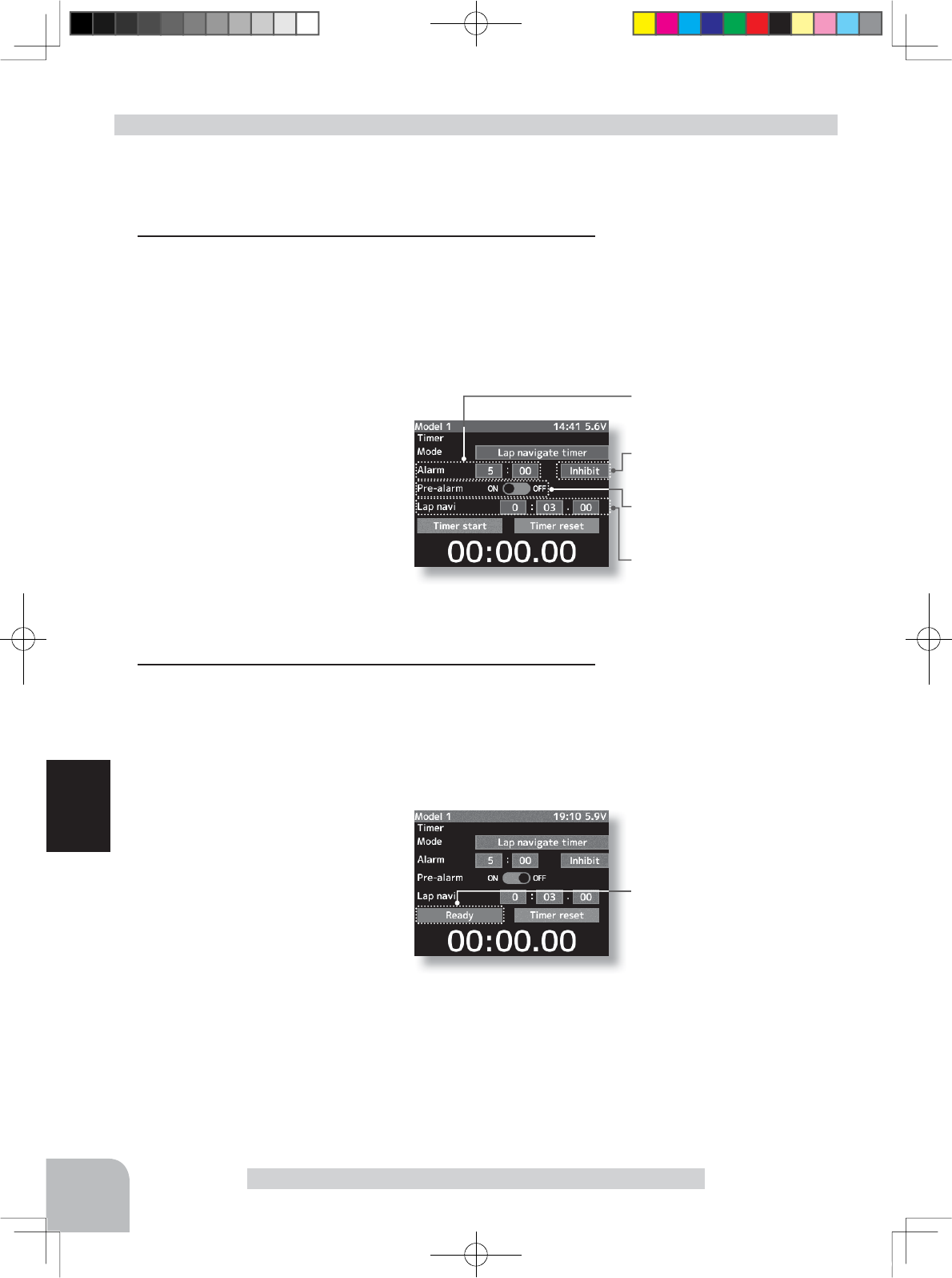
Adjustment buttons
- Use the (+) and (-) buttons to
make adjustments.
- Press the (+) and (-) buttons
simultaneously (approx. 1 sec)
to return to the initial screen.
Switches
Timer start:start / stop
Lap reset :stop / reset
Alarm time
OFF, 1 ~ 99 m
Initial value: 5 m
Grip vibrator type
Inhibit(Off), Type1,2,3
Initial value: Inhibit
Prealarm time
OFF, ON
Initial value: OFF
Navi alarm time (NAVI)
OFF, 1 ~ 99 s
Initial value: 3 s
Status display
Ready:
T
hrottle trigger operation wait
Timer start:
Timer running/ Timer stopped
110
Function
Timer Function
(Preparation)
Select the setting item "Mode" by (JOG) button up or down
operation. Press the (+) or (-) button and select " Lap navigate
timer".
1(Alarm time setting)
Select the setting item "Alarm" by (JOG) button up, down, left, or
right operation and set the alarm time with the (+) and (-) buttons.
The setting item at the right side of the alarm time is the
alarm vibration setting. Select one of the 3 patterns or inhibit
(OFF) by (+) or (-) button.
(Pre alarm time setting)
Select the setting item "Pre-alarm" by
(JOG) button up, down, left, or right op-
eration and set the pre alarm time with
the (+) and (-) buttons.
(Lap navigation time setting)
Select the setting item "Lap navi"
by (JOG) button up, down, left, or
right operation and set the lap navigation alarm (target) time
with the (+) and (-) buttons.
2(Timer start/navigation restart operation)
When the switch ("Timer start") assigned by function select
switch function is pressed, the timer starts.
- Linking only start to the throttle trigger
Select the setting item "
Timer start
"
by (JOG) button up, down, left, or
right operation and press the (+)
and (-) buttons simultaneously for
about 1 second. The set beeps and
the status display changes from
"
Timer start
" to blinking "Ready"
and the set enters the trigger op-
eration ready state. When the trigger is operated at the forward
side, the timer starts. (Status display "
Timer start
")
When your own lap time is less than the target time and the
lap counts overlap, the lap navigation alarm timing is too big.
The alarm timing can be corrected by pressing the switch
("Timer start") during measurement.
Using the navigate timer
4PX-Eng-08-Function-104-156.indd 110 2014/07/18 17:36:09
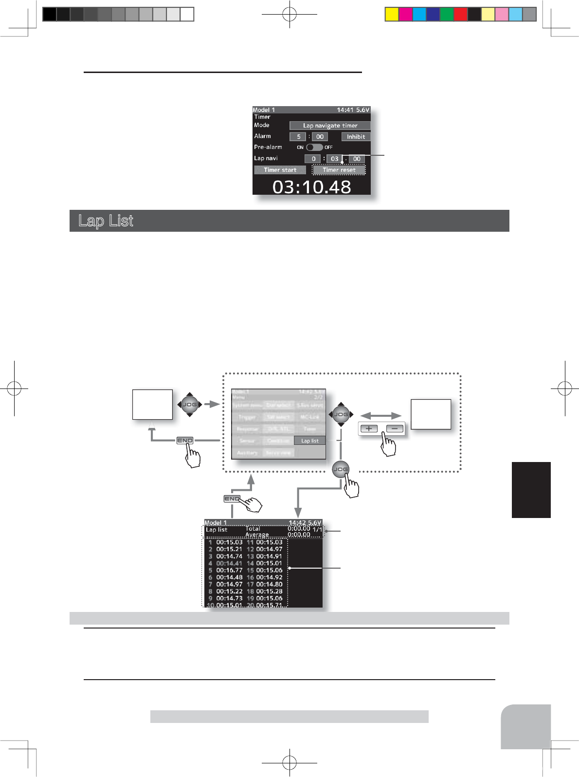
HOME
screen MENU
1screen
or
MENU 2 screen
Timer start/ reset
111
Function
Timer Function/ Lap list
3(Timer stop/reset operation)
When the switch ("Timer reset") assigned by function select
switch function is pressed, the tim-
er is reset. When a switch is not
set, select "Timer reset" by (JOG)
button up or down operation, and
press the (JOG) button. A beeping
sound is generated and the timer
and lap list are reset.
Lap List
Call Lap list when checking the lap memory data (each lap time) memorized by lap timer
(p.105, 109 ) operation.
- After the lap timer is started, the lap time is sequentially memorized at each switch opera-
tion.
-The total time and average time are displayed. The faster time is displayed in red charac-
ters.
-Lap time data is saved in each model data.
-Up to 60 laps can be saved.
-If the lap timer is reset, the lap list is also cleared.
1 (Lap memory check)
The lap list displays up to 30 laps on page 1 and 60 laps on page 2. The page is switched
by (+) or (-) button.
2When ending setting, return to the menu screen by pressing the (END) button.
Using the lap memory
Total time/Average time display
Lap time display
Pres
s
Pres
s
Pres
s
Pre
Pres
s
4PX-Eng-08-Function-104-156.indd 111 2014/07/18 17:36:10