Contents
- 1. User Manual-Part 1 (Page 1-51)
- 2. User Manual-Part 2 (Page 52-111)
- 3. User Manual-Part 3 (Page 112-163)
User Manual-Part 1 (Page 1-51)

2
Thank you for purchasing a Futaba 4PX-2.4GHz system.
Before using your 4PX-2.4GHz system, read this manual carefully in order to use your
R/C set safely.
After reading this manual, store it in a safe place.
IN NORTH AMERICA
Please feel free to contact the Futaba Service Center for assistance in operation, use and
programming. Please be sure to regularly visit the 4PX Frequently Asked Questions web
site at www.futaba-rc.com/faq/. This page includes extensive programming, use, set up and
safety information on the 4PX radio system and is updated regularly. Any technical updates
DQG86PDQXDO FRUUHFWLRQVZLOOEHDYDLODEOHRQWKLVZHESDJH,I\RXGRQRW¿QGWKHDQ-
swers to your questions there, please see the end of our F.A.Q. area for information on con-
tacting us via email for the most rapid and convenient response.
Don’t have Internet access? Internet access is available at no charge at most public libraries,
VFKRROVDQGRWKHUSXEOLFUHVRXUFHV:H¿QGLQWHUQHWVXSSRUWWREHDIDEXORXVUHIHUHQFHIRU
many modelers as items can be printed and saved for future reference, and can be accessed
at any hour of the day, night, weekend or holiday. If you do not wish to access the internet
for information, however, don’t worry. Our support teams are available Monday through
Friday 8-5 Central time to assist you.
OUTSIDE NORTH AMERICA
Please contact your Futaba importer in your region of the world to assist you with any ques-
tions, problems or service needs.
Please recognize that all information in this manual, and all support availability, is based
upon the systems sold in North America only. Products purchased elsewhere may vary. Al-
ways contact your region’s support center for assistance.
FOR SERVICE ONLY:
Futaba Service Center
3002 N. Apollo Drive, Suite 1
Champaign, IL 61822
Phone: 217-398-0007
www.futaba-rc.com/service.html
Email: futabaservice@hobbico.com
FOR SUPPORT :
(PROGRAMMING AND USER QUESTIONS)
Please start here for answers to most questions:
www.futaba-rc.com/faq/
Fax: 217-398-7721
Phone: 217-398-8970 option 2
E-mail: support@futaba-rc.com
4PX-Eng-01-P2-3.indd 2 2014/07/18 12:56:04

3
• No part of this manual may be reproduced in any form without prior permission.
• The contents of this manual are subject to change without prior notice.
7KLVPDQXDOKDVEHHQFDUHIXOO\ZULWWHQ3OHDVHZULWHWR)XWDEDLI\RXIHHOWKDWDQ\FRUUHFWLRQVRUFODUL¿FDWLRQVVKRXOG
be made.
• Futaba is not responsible for the use of this product.
Battery Recycling (for U.S.A.)
The RBRC. SEAL on the nickel-cadmium battery contained in Futaba products
indicates that Futaba Corporation is voluntarily participating in an industry-
wide program to collect and recycle these batteries at the end of their useful
lives, when taken out of service within the United States. The RBRC. program
provides a convenient alternative to placing used nickel-cadmium batteries into the trash or
municipal waste system, which is illegal in some areas.
(for USA)
You may contact your local recycling center for information on where to return the spent
battery. Please call 1-800-8BATTERY for information on NiCd battery recycling in your
area. Futaba Corporation involvement in this program is part of its commitment to protect-
ing our environment and conserving natural resources.
RBRC™ is a trademark of the Rechargeable Battery Recycling Corporation.
$SSOLFDWLRQ([SRUWDQG0RGL¿FDWLRQ
1. This product may be used for models only. It is not intended for use in any application
other than the control of models for hobby and recreational purposes.
2. Exportation precautions:
(a) When this product is exported from the country of manufacture, its use is to be approved
by the laws governing the country of destination for devices that emit radio frequencies. If
this product is then re-exported to other countries, it may be subject to restrictions on such
export. Prior approval of the appropriate government authorities may be required. If you
have purchased this product from an exporter outside your country, and not the authorized
Futaba distributor in your country, please contact the seller immediately to determine if
such export regulations have been met.
(b) Use of this product with other than models may be restricted by Export and Trade Con-
trol Regulations, and an application for export approval must be submitted.
3. Modification, adjustment, and replacement of parts: Futaba is not responsible for un-
DXWKRUL]HG PRGL¿FDWLRQ DGMXVWPHQW DQG UHSODFHPHQW RI SDUWV RQWKLVSURGXFW$Q\VXFK
changes may void the warranty.
4PX-Eng-01-P2-3.indd 3 2014/07/18 12:56:04

4
Table Of Contents
For Your Safety As Well As That Of Others.........................8
Explanation of Symbols................................................................8
2.4GHz System Precautions.........................................................8
High Speed Mode Precautions.....................................................8
Operation Precautions..................................................................9
Battery Handling Precautions ....................................................10
Storage and Disposal Precautions ............................................11
Other Precautions .......................................................................11
Installation ..........................................................................32
Receiver and Servo Connections ..............................................32
Installation Safety Precautions ..................................................33
Before Using ......................................................................12
Features .......................................................................................12
Set Contents ................................................................................14
Transmitter T4PX .........................................................................15
T4PX Nomenclature.................................................................15
Power & Display Switch............................................................16
Power Off Forgotten Alarm & Auto Power Off ..........................16
Low Battery Alarm....................................................................16
Digital Trim Operation (Wheel) .................................................17
Digital Trim Operation (Grip).....................................................17
Mechanical ATL Adjustment.....................................................18
Wheel & Trigger Tension Adjustment........................................18
Trigger Slide Adjustment & Remove The High Point Spring ....19
Battery Replacement Method (4 AA Suze Batteries)...............19
When Using The Optional Battery............................................20
When Charging For The Optional Battery ................................20
Display When Power Switch Turned On ...................................21
Trim/Dial Lock...........................................................................21
Total Timer................................................................................21
Changing Wheel Position And Modifying For Left-hand Use ...22
Using the optional angle spacer...............................................28
Trigger brake lever replacement...............................................28
Non-telemetry LED (telemetry OFF sign) ..................................29
Handling the antenna and card slot and receiver ....................29
About T4PX Antenna................................................................29
Handling an microSD card (commercial product) ....................30
Receiver Terminology...............................................................31
Receiver Installation.................................................................31
4PX-Eng-02-Table-P4-7.indd 4 2014/07/18 17:07:30

5
Before
Using
Function
Map
Functions
For Your Safety
As Well As
That Of Others
Installation
Reference
Initial
Set-Up
Initial Set-Up .......................................................................36
Preparations (Transmitter)..........................................................36
RF Output & Rx Type Check ....................................................36
Receiver Type Change & How To Link .....................................37
Receivers Other Than T-FHSS .................................................39
Servo Type Check ....................................................................39
Trigger Ratio Check..................................................................40
Trims Initial Set-Up ...................................................................40
Function Map ......................................................................42
Menu Selection ............................................................................42
Calling The Menu Screen.........................................................42
Direct Menu..................................................................................44
Functions List..............................................................................45
Functions ...........................................................................46
Receiver Setting/Servo Type.......................................................46
Receiver type (T-FHSS/S-FHSS/FASST(C1), Servo type (Digital/Analog) select
Ch. Reverse..................................................................................47
Servo operation reversing
Sub trim........................................................................................48
Servo center position fine adjustment
End Point Adjuster ......................................................................49
End point adjustment
Acceleration (Throttle Acceleration)..........................................52
Function which adjusts the movement characteristic from the throttle neutral position
Fail Safe/Battery Fail Safe Function ..........................................54
Fail safe, battery fail safe
Steering Curve (EXP) ..................................................................56
Steering operation curve adjustment
Throttle Curve.............................................................................57
Throttle curve adjustment
Steering Speed ............................................................................61
Steering servo delay
Throttle Speed .............................................................................63
Throttle servo delay
Trigger Mode ................................................................................66
Neutral brake function
Throttle servo forward and brake operation proportion setting (Trigger ratio)
Trigger Switch
Idle-Up ..........................................................................................69
Idle up at engine start
Start Function ..............................................................................70
Throttle preset at start function
4PX-Eng-02-Table-P4-7.indd 5 2014/07/18 17:07:30

6
Engine Cut ...................................................................................71
Engine cut off by switch
A.B.S. Function............................................................................73
Pulse brake
Mixing Menu................................................................................78
Brake Mixing ................................................................................80
Front and rear independent brake control for 1/5GP car, etc.
Steering Mixing............................................................................84
Twin servo steering system
4WS Mixing ..................................................................................86
For corolla and other 4WS type vehicles mixing
Gyro Mixing..................................................................................88
Futaba car rate gyro
Dual ESC Mixing..........................................................................90
Front ESC and rear ESC
CPS-1 Mixing ...............................................................................92
Futaba CPS-1 channel power switch
Tilt Mixing.....................................................................................94
Outboard engine
Program Mixing 1,2,3,4,5 ............................................................96
Programmable mixes between arbitrary channels
Switch Select ...............................................................................99
Selection of functions operated by push switches
Dial Select ..................................................................................101
Selection of functions operated by digital dial and digital trim
Timer Function ..........................................................................104
Up, Fuel down, lap, or lap navigation timer
Lap List ......................................................................................111
Lap timer data (lap time, average lap time) check
Model Select ..............................................................................112
Model memory call
Model Name ...............................................................................113
Model memory name set/modify
Model Copy ................................................................................114
Model memory copy
Data Reset..................................................................................116
Model memory reset
MC Link Function (ESC Link) ...................................................117
Special function, Futaba ESC (MC960CR, MC851C, MC602C, MC402CR...etc.)
S.BUS Servo...............................................................................117
Special function, Futaba S.BUS/S.BUS2 servo parameter setup
4PX-Eng-02-Table-P4-7.indd 6 2014/07/18 17:07:31

7
Before
Using
Function
Map
Functions
For Your Safety
As Well As
That Of Others
Installation
Reference
Initial
Set-Up
Reference ..........................................................................157
Specifications ............................................................................157
Optional Parts ...........................................................................158
Warning Displays .....................................................................160
When requesting repair (For U.S.A.)........................................162
Telemetry System......................................................................130
Telemetry Menu......................................................................131
Telemetry :Receiver Battery...................................................132
Telemetry :The Drive Battery .................................................133
Telemetry :RPM......................................................................134
Telemetry :Temperature .........................................................135
Sensor Menu..............................................................................136
Sensor List .............................................................................136
Sensor Reload .......................................................................137
Sensor Register .....................................................................138
Change Slot ...........................................................................139
Condition Function ...................................................................140
Two kinds of data can be set in one model
Response ...................................................................................142
The operation response can be adjusted
System Menu .............................................................................143
Display/ Sound/ LED setting/ Battery/ User name/ Data and Time/
Calibrattion/ Information
Display setting...........................................................................144
Sound Setting ............................................................................146
LED Setting ................................................................................147
Battery Type Setting..................................................................148
User Name..................................................................................149
Data And Time............................................................................150
Information.................................................................................151
Calibration..................................................................................152
Steering Dual Rate/ Throttle ATL "D/R ATL"............................154
Steering angle adjustment while running (dual rate)
Brake side adjustment
Auxiliary Channel "CH3","CH4" ..............................................155
Channel 3/4 servo operation position set/check
Servo View .................................................................................156
Displays servo operation on a bar graph
4PX-Eng-02-Table-P4-7.indd 7 2014/07/18 17:07:31
Warning
Caution
When using the 4PX in the "Digital servo" type, always use it under the following conditions:
Servos :Futaba digital servo (including BLS Series brushless servos)
Receiver’s battery :Matched to the ratings of the receiver and connected digital servo (dry cell battery cannot be used).
Transmitter mode :Digital servo type(See p.39 for setting method.
)
Under other conditions, the set will not operate, or the specified performance will not be displayed even if it operates. In ad-
dition, it may cause servo trouble. Futaba will not be responsible for damage, etc. caused by combination with the products
of other companies.
In addition, the FSU Fail Safe Unit cannot be used because the system is different. Use the fail safe function of the trans-
mitter.
When using analog servos, always switch the 4PX servo type to the "Analog servo" mode.
Transmitter mode :
Analog servo type(See p.39 for setting method.)
Receiver’s battery :
Matched to the ratings of the receiver and connected servo.
The set cannot operate in the "Digital servo" type. Operation in this type will cause trouble with the servo and other equipment.
Digital servos (including BLS Series brushless servos) can also be used in the
"
Analog servo
"
type.
8
For Your Safety As Well As That Of Others
For Your Safety As Well As That Of Others
Use this product in a safe manner. Please observe the following safety precautions at all
times.
Explanation of Symbols
The parts of this manual indicated by the following symbols are extremely important
and must be observed.
Danger
Indicates procedures which may lead to dangerous situations and could
cause death or serious injury as well as superficial injury and physical
damage.
Indicates procedures that may not cause serious injury, but could lead to
physical damage.
Symbols: : Prohibited : Mandatory
Indicates a procedure which could lead to a dangerous situation and may
cause death or serious injury if ignored and not performed properly.
Warning
Caution
Symbols Explanation
2.4GHz System Precautions
Special attention should be paid before turning on the system while other cars are running or
other airplanes are flying because the 2.4GHz RC system could potentially affect them.
Be sure to set the Fail Safe function.
Digital Servo Type Precautions
4PX-Eng-03-Safety-P8-11.indd 8 2014/07/17 12:47:08
Warning
9
For Your Safety As Well As That Of Others
Do not operate outdoors on rainy days, run through puddles of water or use when visibility is lim-
ited.
Should any type of moisture (water or snow) enter any component of the system, erratic operation and loss of control may occur.
Do not operate in the following places.
-Near other sites where other radio control activity may occur.
-Near people or roads.
-On any pond when passenger boats are present.
-Near high tension power lines or communication broadcasting antennas.
Interference could cause loss of control. Improper installation of your Radio Control System in your model could result in serious injury.
Operation Precautions
Do not operate this R/C system when you are tired, not feeling well or under the influence of alco-
hol or drugs.
Your judgment is impaired and could result in a dangerous situation that may cause serious injury to yourself as well as others.
Do not touch the engine, motor, speed control or any part of the model that will generate heat while
the model is operating or immediately after its use.
These parts may be very hot and can cause serious burns.
Always perform an operating range check prior to use.
Problems with the radio control system as well as improper installation in a model could cause loss of control.
(Simple range test method)
Have a friend hold the model, or clamp it down or place it where the wheels or prop cannot come in contact with any ob-
ject. Walk away and check to see if the servos follow the movement of the controls on the transmitter. Should you notice
any abnormal operation, do not operate the model. Also check to be sure the model memory matches the model in use.
Turning on the power switches.
Always check the throttle trigger on the transmitter to be sure it is at the neutral position.
1. Turn on the transmitter power switch.
2. Turn on the receiver or speed control power switch.
Turning off the power switches
Always be sure the engine is not running or the motor is stopped.
1. Turn off the receiver or speed control power switch.
2. Then turn off the transmitter power switch.
If the power switches are turned off in the opposite order, the model may unexpectedly run out of control and cause a very
dangerous situation.
When making adjustments to the model, do so with the engine not running or the motor discon-
nected.
You may unexpectedly lose control and create a dangerous situation.
(Fail safe function)
Before running (cruising), check the fail safe function.
Check Method; Before starting the engine, check the fail safe function as follows:
1) Turn on the transmitter and receiver power switches.
2) Wait at least one minute, then turn off the transmitter power switch. (The transmitter automatically transfers the fail safe
data to the receiver every minute.)
3) Check if the fail safe function moves the servos to the preset position when reception fails.
The fail safe function is a safety feature that minimizes set damage by moving the servos to a preset position when recep-
tion fails. However, if set to a dangerous position, it has the opposite effect. When the reverse function was used to change
the operating direction of a servo, the fail safe function must be reset. Setting example: Throttle idle or brake position
4PX-Eng-03-Safety-P8-11.indd 9 2014/07/17 12:47:10
Caution
Warning
10
For Your Safety As Well As That Of Others
(Only when Ni-MH/Li-ion batteries are used)
Battery Handling Precautions
Never plug the charger into an outlet of other than the indicated voltage.
Plugging the charger into the wrong outlet could result in an explosion or fire.
Never insert or remove the charger while your hands are wet.
You may get an electric shock.
Do not use the transmitter's battery, HT5F1700B or FT2F1700BV2 as the receiver's battery.
Since the transmitter's battery has an overload protection circuit, the output power will be shut down when the high current
load is applied. This may result in runaway or fatal crash.
Do not use commercial AA size Ni-MH and Li-ion batteries.
Quick charging may cause the battery contacts to overheat and damage the battery holder.
Do not short circuit the battery terminals.
A short circuit across the battery terminals may cause abnormal heating, fire and burns.
Do not drop the battery or expose it to strong shocks or vibrations.
The battery may short circuit and overheat; electrolyte may leak out and cause burns or chemical damage.
When the model is not being used, always remove or disconnect the battery.
Leaving the battery connected could create a dangerous situation if someone accidentally turns on the receiver power
switch. Loss of control could occur.
Always check to be sure your batteries have been charged prior to operating the model.
Should the battery go dead while the model is operating, loss of control will occur and create a very dangerous situation.
To recharge the transmitter battery, use the special charger made for this purpose.
Overcharging could cause the battery to overheat, leak or explode. This may lead to fire, burns, loss of sight and many
other types of injuries.
Always keep the charger disconnected from the outlet while it is not in use.
Do this to prevent accidents and to avoid overheating.
When running (cruising), do not use the dry cell battery box at the transmitter.
The accessory dry cell battery box is for performance checks. Do not use it for other than performance checks. The dry cell
battery may be separated from the battery box contacts by shock and the power cut off. If the power is cut off while running
(cruising), a collision may occur. The use of Futaba a genuine NiMH or LiFe battery pack is strongly recommended.
Do not connect the charger when the battery is not connected.
A load will be applied to the circuit and the transmitter may be damaged.
4PX-Eng-03-Safety-P8-11.indd 10 2014/07/17 12:47:13
Warning
Warning
Caution
11
For Your Safety As Well As That Of Others
Storage and Disposal Precautions
Do not leave the radio system or models within the reach of small children.
A small child may accidentally operate the system. This could cause a dangerous situation and injuries. Ni-Cd batteries
can be very dangerous when mishandled and cause chemical damage.
Do not throw Ni-MH/LiFe batteries into a fire. Do not expose batteries to extreme heat. Also do
not disassemble or modify a battery pack.
Overheating and breakage will cause the electrolyte to leak from the cells and cause skin burns, loss of sight, and other
injuries.
When the system will not be used for any length of time, store the system with HT5F1700B batteries
in a discharged state. Be sure to recharge the batteries prior to the next time the system is used.
If the batteries are repeatedly recharged in a slightly discharged state, the memory effect of the Ni-Cd battery may con-
siderably reduce the capacity. A reduction in operating time will occur even when the batteries are charged for the recom-
mended time. (After discharge to 1cell E.V.=1V)
<Battery Electrolyte>
The electrolyte in Ni-MH/Ni-Cd batteries is a strong alkali. Should you get even the smallest amount of the electrolyte in your
eyes, DO NOT RUB. Wash immediately with water, and seek medical attention at once. The electrolyte can cause blindness.
If electrolyte comes in contact with your skin or clothes, wash with water immediately.
Do not store your R/C system in the following places.
- Where it is extremely hot or cold.
- Where the system will be exposed to direct sunlight.
- Where the humidity is high.
- Where vibration is prevalent.
- Where dust is prevalent.
- Where the system would be exposed to steam and condensation.
Storing your R/C system under adverse conditions could cause deforma-
tion and numerous problems with operation.
If the system will not be used
for a long period of time, re-
move the batteries from the
transmitter and model and
store in a cool, dry place.
If the batteries are left in the transmit-
ter, electrolyte may leak and damage
the transmitter. This applies to the
model also. Remove the batteries
from it also to prevent damage.
Do not expose plastic parts to fuel, motor spray, waste oil or exhaust.
The fuel, motor spray, waste oil and exhaust will penetrate and damage the plastic.
Always use only genuine Futaba transmitters, receivers, servos, ESCs (electronic speed con-
trols), Ni-MH/Ni-Cd/Li-ion batteries and other optional accessories.
Futaba will not be responsible for problems caused by the use of other than Futaba genuine parts. Use the parts speci-
fied in the instruction manual and catalog.
Other Precautions
<Battery Recycling>
A used battery is a valuable resource. Insulate the battery terminals and dispose of the battery by taking it to a battery recycling center.
4PX-Eng-03-Safety-P8-11.indd 11 2014/07/17 12:47:15

12
Before Using
-High balance design
Rigidity is improved and weight is lightened 15g from that of the previous model by design that
effectively impacts the age and the use of aluminum at part of the frame.
-Full color LCD
Excellent outdoor visibility OVGA3.5 inch backlighted color TFT liquid crystal. Enlarged dis-
play improves visibility tremendously.
-High response & telemetry T-FHSS
Increased response T-FHSS transmission increases response by 30% over that of the previous
model. In addition, receiver power supply voltage and other information from the receiver can be
displayed at the transmitter by fast, stable bidirectional transmission.
-Updateable software
Software can be updated by microSD card. Model data can also be saved in a microSD card. In
addition, telemetry log data can be saved.
-Model memory for 40 models
Model names can use up to 10 letters, numbers, and symbols, so that logical names may be used.
A model memory with different setups can be created by using the model copy function.
-Brake mixing for large cars
Brake mixing of the front and rear wheels of 1/5GP and other large cars can be adjusted inde
pendently.
-Steering mixing
Smooth cornering is possible by independent left and right steering servo setting.
-4WS mixing for crawlers and other 4WS type
This function can be used with crawlers and other 4WS type vehicles.
-Dual ESCs mixing for crawlers cars
ESC at the front and rear are controlled independently.
-Gyro mixing
The sensitivity of Futaba car rate gyros can be adjusted from the T4PX.
-CPS mixing
/('OLJKWLQJDQGÀDVKLQJFRQWUROXVLQJRXU&36FKDQQHOSRZHUVZLWFKFDQEHPDWFKHGWR
steering and throttle operation by switch only.
-S.BUS servo
This is a special function that allows setting of the parameters of our S.BUS servo whose set-
tings are changed by using PC Link software.
-MC-Link
This is a dedicated function which allows setting of the contents of the Link software which
makes possible Futaba speed controller (ESC), MC960CR, MC950CR, MC850C, MC851C,
MC602C, MC402CR, etc. variable frequency and other data changes by PC at the T4PX.
Before Using
Features
4PX-Eng-04-Before-P12-31.indd 12 2014/07/18 16:59:26

13
Before Using
-Response change function
The operation response can be set in 50 steps to match your preference and the course and ve-
hicle.
-Anti-skid braking system (A.B.S.)
This function applies the brakes so that the tires of gasoline engine cars, etc. do not lose their
grip on the road even when braking at corners.
-Throttle acceleration
Gasoline engine cars have a time lag before the clutch and brakes become effective.
The TH-ACCEL function reduces this time lag.
-Throttle speed
Sudden trigger operation on a slippery road surface will only cause the tires to spin and the
model to not accelerate smoothly. By setting the throttle speed function, operation can be per-
formed smoothly and easily. It also suppresses battery consumption.
-Steering speed
When you sense that the steering servo is too fast, etc., the servo operating speed (direction that
suppresses the maximum speed) can be adjusted.
-Non-telematry LED
:KHQWKHWHOHPHWU\IXQFWLRQLV2))WRFRQ¿UPWKDWWKHWHOHPHWU\IXQFWLRQLVQRWRSHUDWLQJ
-Racing timer
The lap timer can record 99 lap times, total time, and average lap time. The timer can also be
started automatically by trigger operation. The race time and audible alarm can be set.
The 4PX also has a navigation timer effective during practice runs. The target lap and re-/fuel-
ing time are indicated by an audible alarm. An up timer and down timer are also provided.
-Function select dial function
This function assigns functions to dials (digital trim, grip dial, knob). The step amount and oper-
ating direction can also be adjusted. Trim positioning at each model call is unnecessary because
all the dials are digital.
-Function select switch function
This function assigns functions to 3 switches. The operating direction can also be set.
-Wheel & Trigger position can be changed
The wheel position can be offset by using an accessory APA wheel position offset adapter.
The wheel angle can also be adjusted.
The position of the throttle trigger can be moved forward and backward.
-Trigger brake lever replacement
The trigger brake lever is selected from a narrow nylon type and wide type
-Edit button lock & trim/dial lock functions
Lock functions which prohibit setting and operation by transmitter edit buttons, trim, and dials
are provided.
-Left-handed support
The left and right installation direction of the wheel section can be reversed.
-Tension adjustment function
The tension of the steering wheel & throttle trigger springs can be adjusted from the outside.
4PX-Eng-04-Before-P12-31.indd 13 2014/07/18 16:59:26
14
Before Using
$IWHURSHQLQJWKHER[¿UVWFKHFNLIWKHFRQWHQWVFRQIRUPWRWKHIROORZLQJ7KHFRQWHQWVGH-
pend on the set as shown below.
Set Contents
Transmitter T4PX
Receiver R304SB or R304SB-E
Miscellaneous
Dry battery holder
*Installed in transmitter.
Receiver switch
Wheel offset adapter(APA)
Wheel adapter 32deg
Trigger brake lever (narrow type)
Miniature screwdriver
Instruction manual
- If any of the set contents are missing, or you have any questions, please contact your
dealer.
Caution
When using the T4PX in the "Digital servo" type, always use it under the following conditions:
Servos:Futaba digital servo (including BLS Series brushless servos)
Receiver’s battery:
Matched to the ratings of the receiver and connected digital servo (dry cell battery cannot be used).
Transmitter servo type:Digital servo type (See page 39 for setting method.)
Under other conditions, the set will not operate, or the specified performance will not be displayed even if it operates. In ad-
dition, it may cause servo trouble. Futaba will not be responsible for damage, etc. caused by combination with the products
of other companies.
In addition, the FSU Fail Safe Unit cannot be used because the system is different. Use the fail safe function of the trans-
mitter.
When using analog servos, always switch the T4PX servo type to the "Analog servo" type.
Transmitter mode:"Analog servo" type (See page 39 for setting method.)
Receiver’s battery:
Matched to the ratings of the receiver and connected digital servo.
The set cannot operate in the "Digital servo" type. Operation in this type will cause trouble with the servos and other equip-
ment. Digital servos (including BLS Series brushless servos) can also be used in the "Analog servo" type.
Always use only genuine Futaba transmitters, receivers, servos, ESCs (electronic speed controls),
Ni-MH/Ni-Cd/Li-ion batteries and other optional accessories.
Futaba will not be responsible for problems caused by the use of other than Futaba genuine parts. Use the parts specified
in the instruction manual and catalog.
4PX-Eng-04-Before-P12-31.indd 14 2014/07/18 16:59:27
15
Before Using
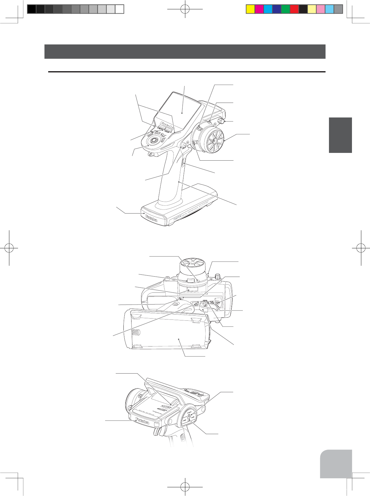
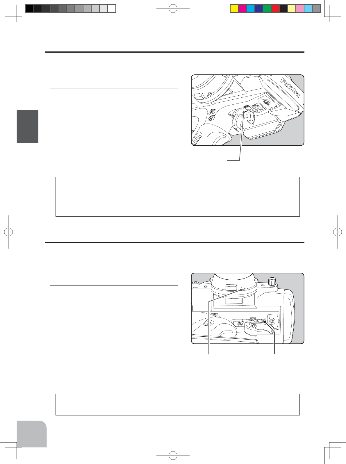
High point spring
Grip Handle
A vibration motor is built into the grip handle and
racing timer time-up, low battery alarm, telemetry
alarm, etc. can be generated by vibration.
Earphone Jack
Telemetry data can be listened to with commer-
cial earphones.
Non-telematry LED
Charging jack (interior right side)
Communication port (interior left side)
(Lights when the telemetry function is off.)
Convenient in trigger switch posi-
tion checks.
7KHVZLWFKHVGLDODQGWULPPHUVLQWKH¿JXUHDUHVKRZQLQWKHLQLWLDOVHWWLQJSRVLWLRQ
Antenna
Digital Dial (DL1)
Mechanical ATL
adjusting screw
Throttle trigger
Power&Display
switch
Digital Trim 2 (DT2)
(default throttle trim)
Digital Trim1 (DT1)
(default steering trim)
Digital Trim4 (DT4)
Digital Trim3 (DT3)
Digital Trim5 (DT5)
(default dual rate)
Steering wheel
Push switch 2 (PS2)
Push switch 1 (PS1)
Push switch 5 (PS5)
Push switch 3 (PS3)
Push switch 4 (PS4)
LED
LCD screen
Edit buttons
Nomenclature
Transmitter T4PX
Digital Trim6 (DT6)
(default brake rate)
Wheel tension
adjusting screw
Trigger tension
adjusting screw
Battery cover
Cover
Trigger slide adjusting screw
4PX-Eng-04-Before-P12-31.indd 15 2014/07/18 16:59:27
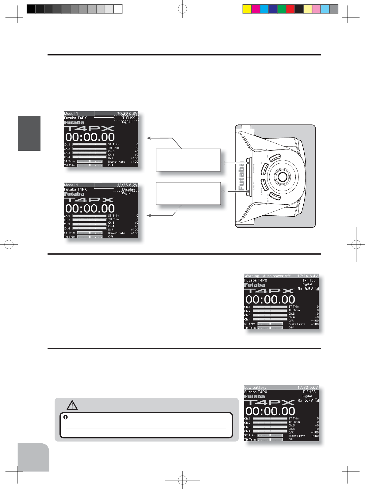
DISP ON
Radio waves are not being
transmitted
PWR ON
Radio waves are being
transmitted
16
Before Using
Power & Display Switch
The power switch and display switch are push switches.
When the power switch (PWR) is held down, operation starts by transmitting radio waves. When
the display switch is held down, the transmitter side data can be checked and set. When the power
is turned off, if the power switch or display switch is held down, the power is turned off. If both
switches are pressed simultaneously, the power is turned off quickly.
Power Off Forgotten Alarm & Auto Power Off
At T4PX initialization, if steering wheel, throttle trigger, push switch, edit button, or other
operation is not performed within 10 minutes, an audible alarm will sound and the message
"Warning: Auto power off" will appear.
If steering wheel, throttle trigger, push switch, edit button or other
operation is performed, the alarm is reset. Also turn off the power
when the transmitter is not in use. If the alarm is not reset, the auto
power off function will automatically turn off the power after 5
minutes. If you do not want to use this alarm and the auto power off
function, they can be disabled by system setting (p.148).
Low Battery Alarm
If the transmitter battery voltage drops below the usable range, an audible alarm will sound
and "Low battery" will be displayed. Since the usable range of LiFe and NiMH batteries and
LiFe batteries is different, the power supply used must be set by system setting. If the battery
goes dead while running (cruising), since there is the danger of collision, immediately recover
the vehicle (boat) and stop running (cruising).
Warning
When a low battery alarm is generated, cease operation immedi-
ately and retrieve the model.
If the battery goes dead while in operation, you will lose control of the model.
"T-FHSS, S-FHSS, FASST" is displayed
"Display" is displayed
4PX-Eng-04-Before-P12-31.indd 16 2014/07/18 16:59:28
17
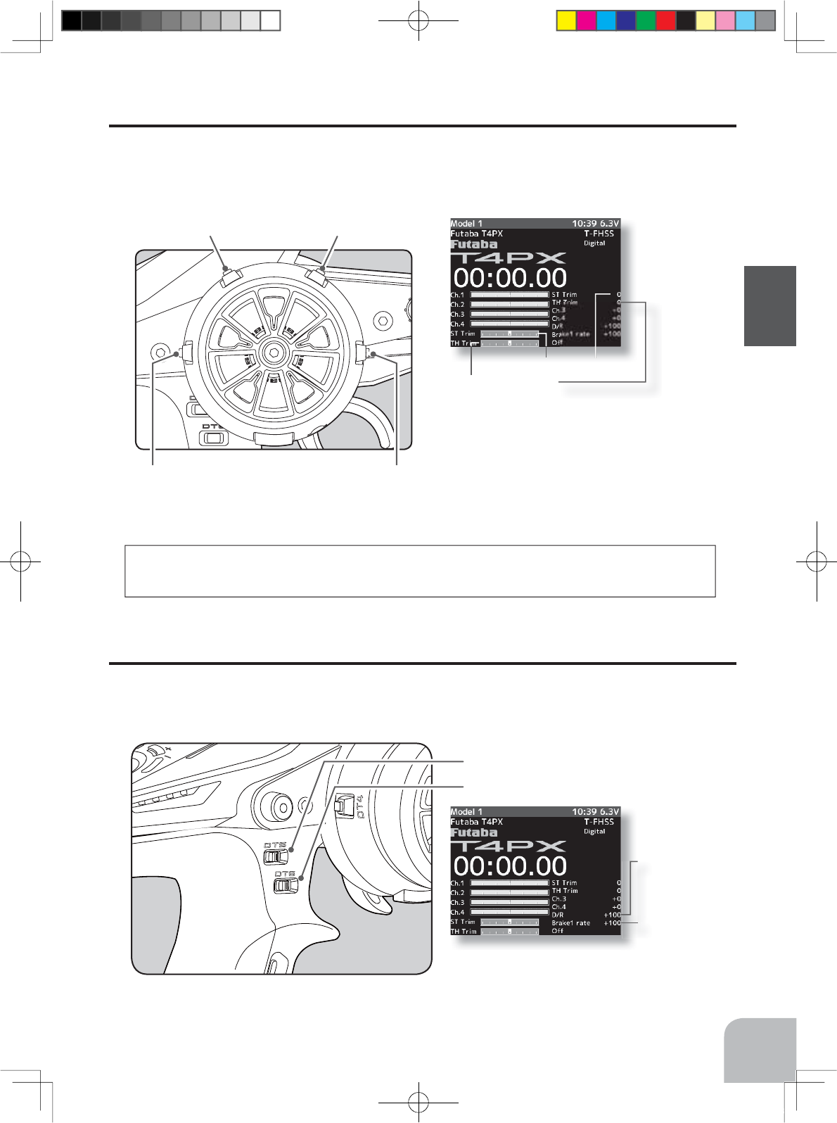
Before Using
• Each step is indicated by a tone.
• When the trim exceeds the maximum trim adjust-
ment range, the beep will change and the servo will
not move any farther. Return to the neutral position
(center) by pressing both the push button switches
simultaneously for about one second.
• Reset when tilted to the transmitter body side while
pressing each trim button in the wheel center direc-
tion.
DT1DT2
DT4 DT3
Digital Trim Operation (Wheel)
(Initial settings: DT1: Steering trim, DT2: Throttle trim, DT3: Channel 3, DT4: Channel 4)
Operate digital trim by tilting each trim lever up and down or left and right. The current trim po-
sition is displayed on the LCD screen. However, operation is impossible when trim/dial lock (P21)
is set.
Digital Trim Operation (Grip)
(Initial setting: DT5; Steering D/R, DT6; Brake rate)
Operate the
lever
by turning them. The current set value is displayed on the LCD screen. How-
ever, this operation cannot be performed when the trim/dial lock (p.21) function is set.
Steering trim display
Throttle trim display
Brake rate
display
Steering dual rate
display
Trim Operation
• Each step is indicated by a tone.
• When the trim exceeds the maximum trim adjust-
ment range, the tone will change pitch and the ser-
vo will not move any farther.
With the center trim feature, trim adjustments have no effect on the maximum servo
travel. This prevents the linkages from binding when adjustments are made.
Steering dual rate DT5
Brake rate (Brake1) DT6
4PX-Eng-04-Before-P12-31.indd 17 2014/07/18 16:59:28
18
Before Using
Mechanical ATL
adjusting screw
Adjustment
1 Using a 1.5mm hex wrench, adjust the trigger
brake (reverse) stroke. (The screw moves the
throttle trigger stopper.)
• When the screw is turned clockwise, the stroke becomes
narrower. Adjust the stroke while watching the screw.
Note:
Mechanical ATL Adjustment
Make this adjustment when you want to decrease the stroke of the brake (back) side of the
throttle trigger for operation feel.
Wheel & Trigger Tension Adjustment
Make this adjustment when you want to change the wheel or trigger spring’s tension.
Adjustment
1 Using a 1.5mm hex wrench, adjust the wheel
spring tension by turning the screw inside the
adjusting hole in the arrow direction.
• The spring is set to the weakest tension at the factory.
• When the adjusting screw is turned clockwise, the spring
tension increases.
Note:
Wheel tension
adjusting screw
Once you have changed the mechanical stroke on the brake side, be sure to adjust the
scale of the throttle channel accordingly by using the "Adjuster Function" (p.128).
Due to this change, you also need to adjust in most cases the travel of the throttle servo
by using "Data Setting."
The adjustment range is up to 7 to 8 turns from the fully tightened (strongest) position. If
turned farther than this, the adjusting screw may fall out.
Trigger tension
adjusting screw
4PX-Eng-04-Before-P12-31.indd 18 2014/07/18 16:59:28
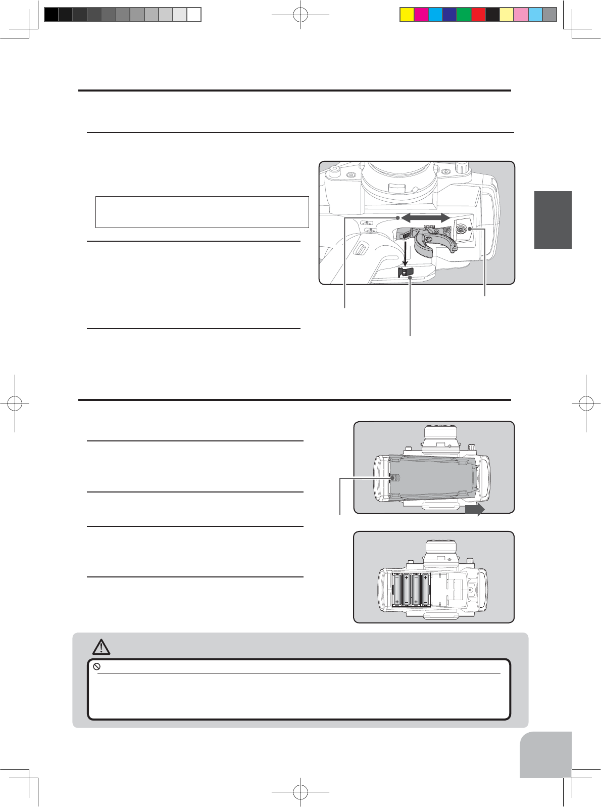
Battery cover
Slide battery cover while pressing here.
19
Before Using
Adjustment
1Using a 2.0mm hex wrench, loosen the trigger slide mounting screw by turning it slightly
counterclockwise.
Always loosen this screw.
High point spring can be re-
moved with radio pliers, etc.
Please adjust it with-
in the range of mark.
2Adjust the trigger slide position within the
marked range.
The high point spring can be removed by moving to the
fastest from the grip.
When the high point spring was removed, perform
throttle side correction by adjuster function (p.152).
3Retighten the mounting screw loosened at
step 1 and fasten the trigger slide.
Note:
If the trigger slide screw is turned too
much, the screw may fall out.
Caution
Trigger Slide Adjustment & Remove The High Point Spring
The throttle trigger position can be moved forward and backward.
Trigger slide
mounting screw
Battery Replacement Method
1Remove the battery cover from the transmit-
ter by sliding it in the direction of the arrow in
the figure.
2Remove the used batteries.
3Load the new AA size batteries. Pay very
close attention to the polarity markings and
reinsert accordingly.
4Slide the battery cover back onto the case.
Battery Replacement Method (4 AA Size Batteries)
Load the four batteries in accordance with the polarity markings on the battery holder.
When running (cruising), do not use the dry cell battery box at the transmitter.
The accessory dry cell battery box is for performance checks. Do not use it for other than performance checks. The dry
cell batteries will be separated from the battery box contacts by shock and the power may be cut off. There is the danger of
collision if the power is cut while running (cruising). The use of Futaba genuine NiMH or LiFe batteries is strongly recom-
mended.
4PX-Eng-04-Before-P12-31.indd 19 2014/07/18 16:59:29
Charging jack
20
Before Using
Caution
When closing the battery cover, be
careful that the battery cover does
not pinch the battery lead wires.
Shorting of the battery lead wires may lead
to fire and abnormal heating and cause
burns or fire disaster.
Battery Replacement Method
1Refer to the previous description and remove
the transmitter battery cover.
2After removing the dry cell battery box from
the transmitter, disconnect the connector.
3Insert the connector of the new battery and
load the new battery into the transmitter.
4Finish by installing the battery cover.
When Using The Optional Battery
When using an optional rechargeable battery, replace the battery as described below.
-Always use the optional HT5F1800B, FT2F1700BV2, FT2100BV2 rechargeable battery.
-The type of power source used must be set by system setting (p.148).
-When the transmitter will not be used for a long time, remove the battery.
Warning
Never plug it into an outlet other than the indicated voltage.
Plugging the charger into the wrong outlet could result in an explosion or fire.
Do not insert and remove the charger when your hands are wet.
It may cause an electric shock.
Always use the special charger or a quick charger for digital proportional R/C sets to charge a digital
proportional R/C set Ni-MH or LiFe battery.
Overcharging a Ni-MH battery can result in burns, fire, injuries, or loss of sight due to overheating, breakage, or electrolyte
leakage.
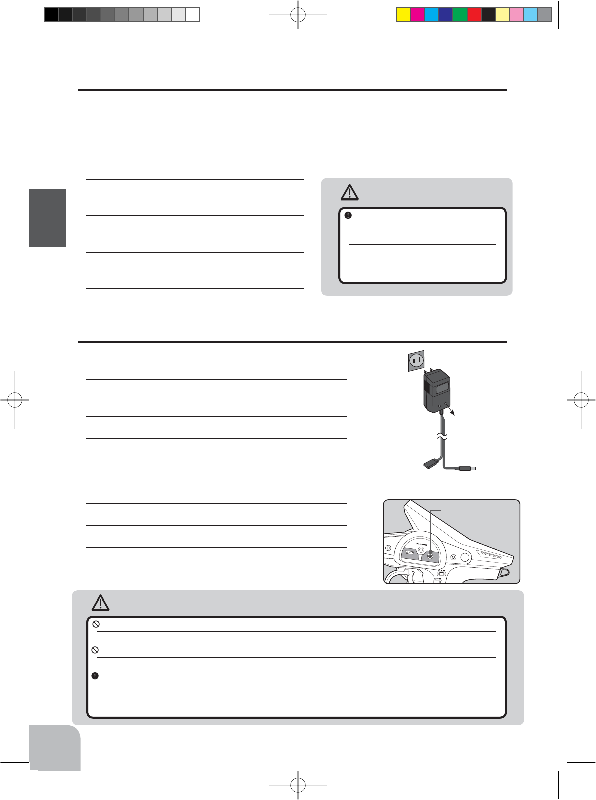
AC outlet
Charger
Transmitter
charging LED
To transmitter
charging jack
To receiver
Ni-Cd battery
Charge Of A NiMH Battery
(Example: When using the HT5F1800B with the special charger)
1Plug the transmitter cord of the special charger into the
charging jack on the rear of the transmitter.
2Plug the charger into an AC outlet.
3Check that the charging LED lights.
Charge Of A LiFe Battery
(Example: When using the
FT2F1700BV2/2100BV2
with the special charger)
1Remove the battery cover.
2Disconnect the battery from the T4PX.
3Balance charging cannot be done through the transmit-
ter, you must remove the LiFe battery to do this.
When Charging For The Optional Battery
4PX-Eng-04-Before-P12-31.indd 20 2014/07/18 16:59:29
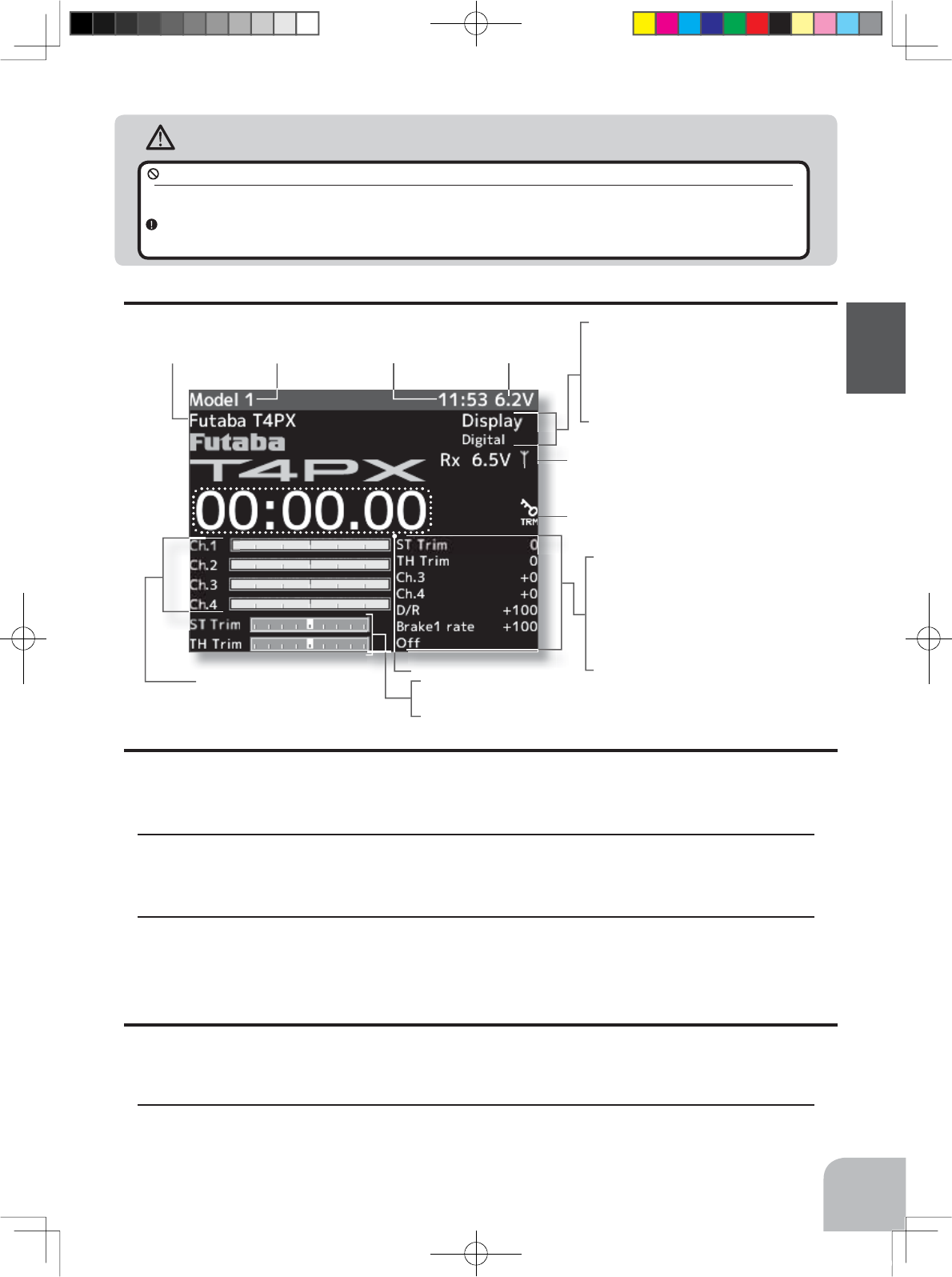
Upper:The current receiver type is dis-
played. (T-FHSS /S-FHSS /FASST)
When turned on by DSP switch , "Display"
is displayed
Lower: Servo type
(Digital servo /Analog servo)
21
Before Using
Caution
When the charger is not in use, disconnect it from the AC outlet.
Do this to prevent accidents and to avoid overheating.
If the power is turned on during charging, an RF error will be displayed and an audible alarm will
sound. Immediately turn off the power. (See p.161)
DT1
DT2
DT3
DT4
DT5
DT6
DL1
Total timer or clock
display (H:M)
Battery voltage
display
Upper: Steering trim display
Lower: Throttle trim display
Racing timer
Trim/dial lock display
Display When Power Switch Is Turned On
Function names and rate as-
signed to dials are displayed.
Model name
(15 characters)
User name
(15 characters)
Trim/Dial Lock
T4PX setup and operation by digital trim DT1, DT2, DT3, DT4, DT5 and DT6 and dials
DL1 can be prohibited.
Setting
1When the (-) button is pressed for about 1 second at the initial screen, a confirmation beep
is generated and the trim/dial lock display mark appears on the screen.
Clearing
1Edit button lock and trim/dial lock can be cleared in the initial screen state by the same
method as the setting described above. (The trim/dial lock display disappears from the
screen.)
Total Timer
The total timer shows the accumulated time from last reset.
The total time does not change even when the model changes.
Reset method
1In the initial screen state, hold down the (+) and (-) buttons simultaneously for 1 second.
* The total timer display counts up from 1 minute to 99hours 59 minutes.
Telemetry function
Receiver -> Transmitter
The reception strength is shown.
Servo operation of each
channel can be checked.
4PX-Eng-04-Before-P12-31.indd 21 2014/07/18 16:59:30
22
Before Using
1Hold the wheel and remove the screw.
(Using a 2.5 mm hex wrench.)
• Obtain 2.5mm hex wrenchs./ Remove the battery.
2Pull off the wheel and wheel adapter.
3Install the steering wheel and the 32
deg wheel adapterusing the screw.
(Using a 2.5 mm hex wrench.)
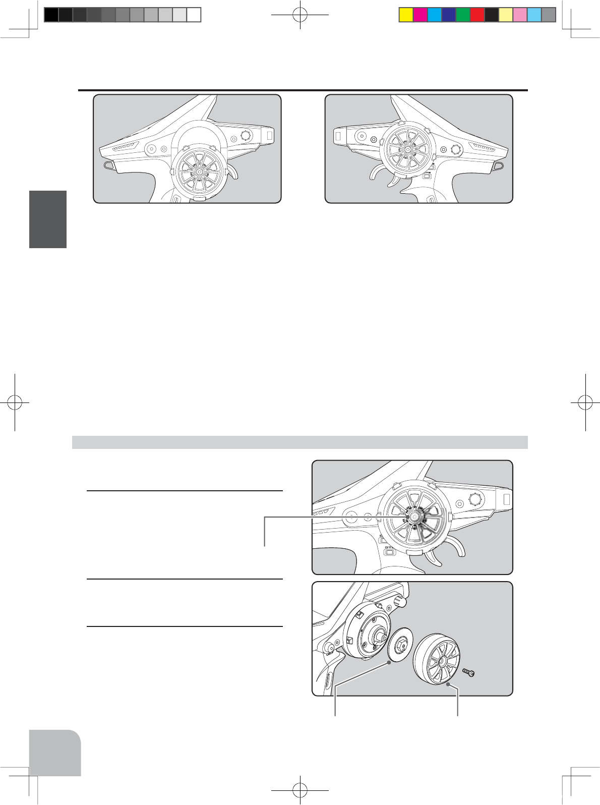
Exchange procedure to wheel adaptor 32 deg
Changing Wheel Position And Modifying For Left-hand Use
Changing the wheel position
The wheel position can be offset by using the
accessory APA wheel position offset adapter.
6HHSDJHIRUWKHPRGL¿FDWLRQPHWKRG
Angle can be adjusted
The angle can be finely adjusted by adjusting the steering wheel unit installation. (See the
modification method on the next page for the adjustment details.)
The operating angle of the wheel can be adjusted
The operating angle of the wheel can be changed from 34 deg to 32 deg by installing the
32 deg wheel adjuster. (See "Exchange procedure to wheel adaptor 32 deg" below for the
replacement procedure.
If you install the 32 deg wheel adapter, be sure to adjust the scale of the steering channel
accordingly by using the "Adjuster Function" (p.152).
Modifying for left-hand use
The wheel section left and right installa-
tion direction can be reversed.
6HHSDJHIRUWKHPRGL¿FDWLRQPHWKRG
Steering wheel
mounting screw
WheelWheel adapter
4PX-Eng-04-Before-P12-31.indd 22 2014/07/18 16:59:30
A
B
Connector
Wheel unit Switch unit
Steering wheel unit
Unit mounting screws
23
Before Using
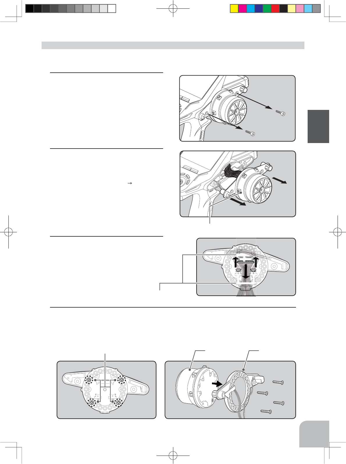
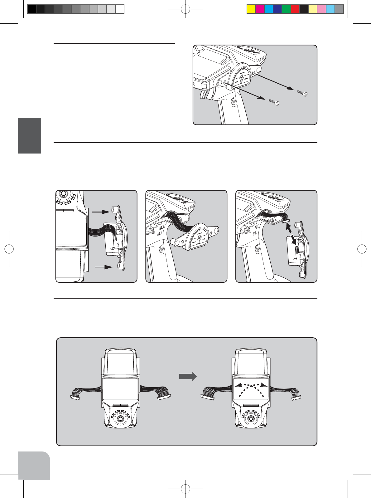
1Remove the 2 steering wheel unit
mounting screws.
(Using a 2.5 mm hex wrench.)
Remove the 2 mounting screws completely from
the transmitter body.
• Obtain 2.5mm hex wrenchs./ Remove the battery.
• The length of the screws used at each part differs. When reassembling the steering wheel unit, always use the
specified screws.
2Being careful that the wiring is not too
tight remove the steering unit.
- Remove the steering unit slowly so that the inter-
nal wiring is not pulled unreasonably.
- Removal is easy if performed in A B order.
3Remove the 3 connectors from the PC
board.
Remember the direction of the connectors.
4Using a Phillips screwdriver, remove the 4 screws (2.5x15mm tapping screw) mounting the
wheel unit and switch unit.
Installing the accessory APA steering wheel offset adapter
4PX-Eng-04-Before-P12-31.indd 23 2014/07/18 16:59:31
Marking
APA rear cover
Switch unit and APA mounting screws
(2.5x10mm tapping screws)
Wheel unit and APA mount-
ing screws (2.5x19mm tapping
screws)
Adapter APA
24
Before Using
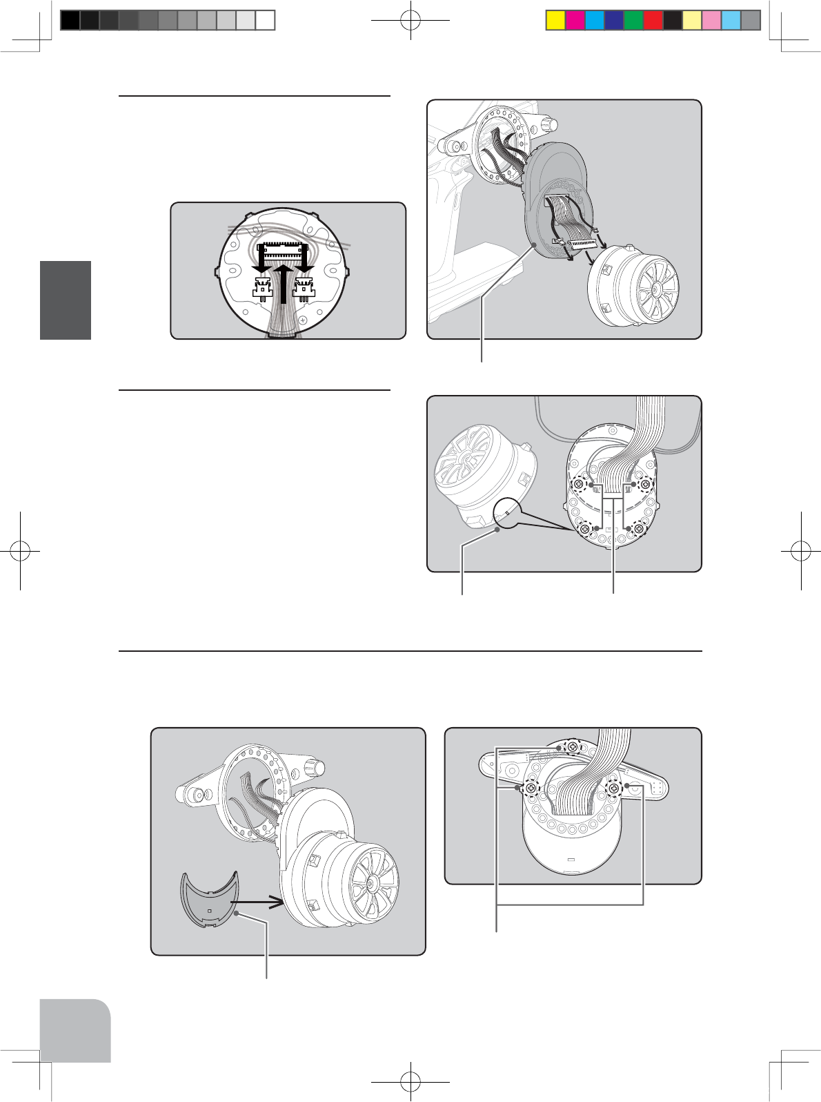
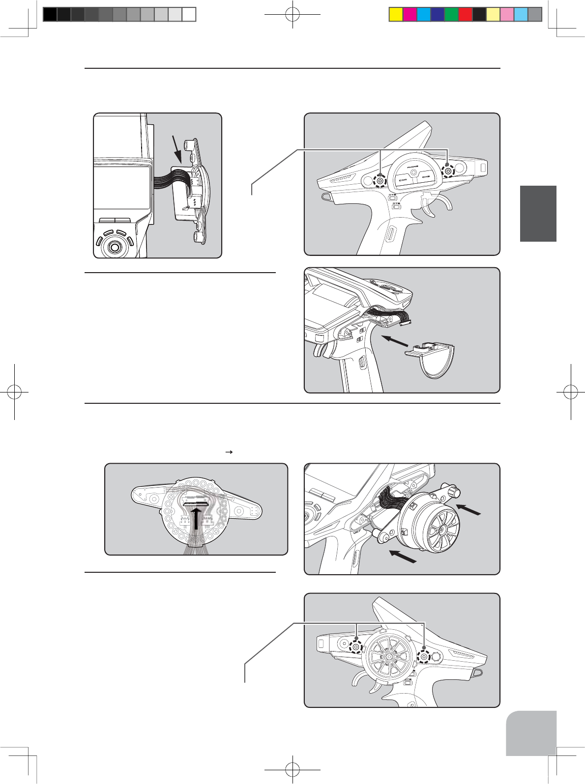
7Using a Phillips screwdriver fasten the switch unit and APA. Use the 2.5x10mm tapping
screws in the accessories bag. Next, install the APA rear cover. Be careful that the length of
the screws is correct.
6Using a Phillips screwdriver fasten the
wheel unit and APA at the desired angle
using the 2.5x19 tapping screws in the
accessory bag. Be careful that the screw
length is correct. Be careful that the wir-
ing does not get pinched. The angle can
be adjusted, but check the marking point
on the wheel unit and install the screws.
Screws can be installed at 4 places, but installation
at 4 places may be impossible due to the wheel
unit mounting angle.
5Pass the wiring from the transmitter and
the charge unit wiring through the hole
in the APA as shown in the figure and
insert the 3 connectors at their original
positions on the wheel unit PC board.
4PX-Eng-04-Before-P12-31.indd 24 2014/07/18 16:59:32
B
A
Steering wheel unit
mounting screws
25
Before Using
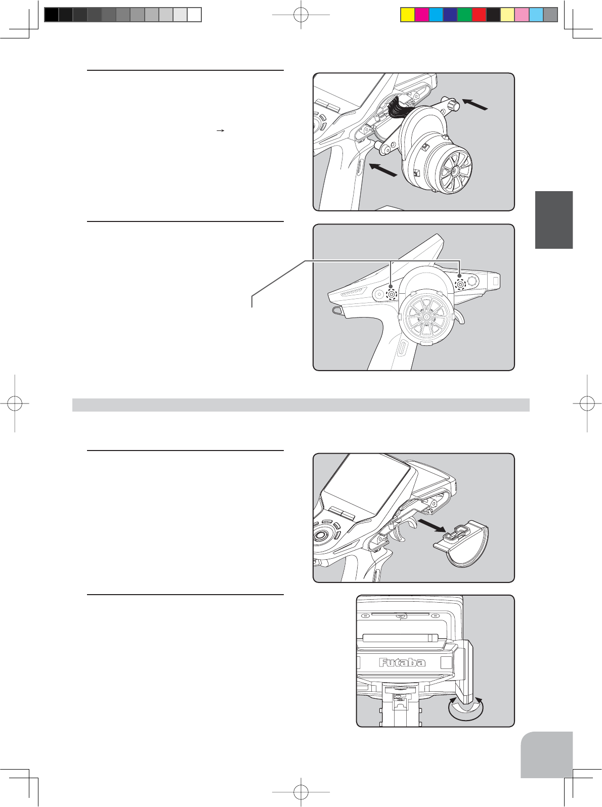
9Install the assembled steering wheel
unit and APA to the transmitter using the
screw (3.0x12mm cap tapping screw)
supplied.
(Using a 2.5 mm hex wrench.)
8Install the assembled steering unit to the
transmitter body.
Install slowly so that the wiring is not pinched.
Installation is easy if inserted in A B order.
1Slowly pull out the PS5 switch cap and
mounting plate in the arrow direction.
Be careful that the switch body does not get
caught and damaged.
2Next, remove the opposite side charge
unit. Refer to the figure and secure the
arrow part with tape, etc.
The tape is removed at the end of left-hand modi-
fication.
• Obtain 2.5mm hex wrenchs.
• Refer to 1-2 (P24) of the APA for the wheel position change installation method and remove the wheel unit. Only
remove the 15WIRE connector. (See p.26)
Modifying for left-hand use
4PX-Eng-04-Before-P12-31.indd 25 2014/07/18 16:59:32
15 WIRE8 WIRE 15 WIRE 8 WIRE
Right-hand Left-hand
26
Before Using
3Using a 2.5mm hex wrench, remove the
mounting screws (3.0x1.2mm cap) of
the opposite side charge unit.
Remove the 2 mounting screws completely from
the transmitter body.
4Being careful that the wiring is not too tight slowly remove the charge unit. Remove the
connector from the PC board.
Remember the direction of the connector.
5Interchange the 15WIRE wiring connector of the steering unit and the 8WIRE wiring con-
nector of the charge unit, while being careful that the wiring is not too tight.
4PX-Eng-04-Before-P12-31.indd 26 2014/07/18 16:59:33
B
A
Charge unit
mounting screws
Steering wheel unit
mounting screws
27
Before Using
6Insert the 8WIRE wiring connector onto the charge unit connector, and install the charge
unit and transmitter body with the mounting screws.
7Install the PS5 switch cap and mounting
plate removed at step 1 at the opposite
side of the transmitter body.
Be careful that the switch body does not get
caught and damaged.
8Insert the 15WIRE wiring connector onto the steering unit, and install the steering unit to
the transmitter body.
Install slowly so that the wiring does not get pinched.
Installation is easy when inserted in A B order. (Figure at the right)
9Install the assembled steering wheel
unit and APA to the transmitter using the
screw (3.0x12mm cap tapping screw)
supplied.
(Using a 2.5 mm hex wrench.)
Peel the tape installed at step 2.
4PX-Eng-04-Before-P12-31.indd 27 2014/07/18 16:59:34
2.6x10mm
tapping screws
2.6x15mm
tapping screws
Angle spacer
2.6x10mm
tapping screws
2.6x19mm
tapping screws
Mount the angle spacer and wheel unit with
2.6x15mm tapping screws.
2.6x10mm
tapping screws
2.0x6 cap crew
2.6x10mm
tapping screws
Mount the APA adapter and
wheel unit with 2.6x19mm
tapping screws.
28
Before Using
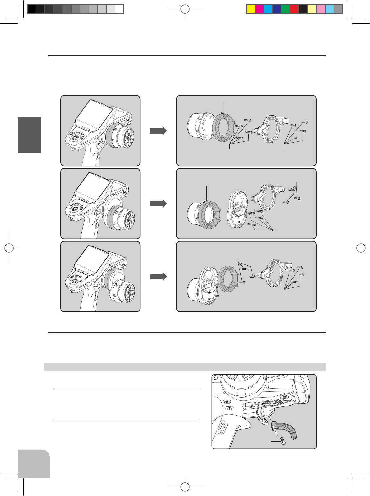
Using the optional angle spacer
The wheel mounting angle can be changed by using the optional angle spacer.
Three 2.5x10mm tapping screws are supplied with the angle spacer.
When using and not using the APA, refer to the following installation.
Obtain a Phillips screwdriver. Be careful of the length of the screws used.
Actually, since there is wiring, the wheel is assembled by passing the screws through each part.
Trigger brake lever replacement
The trigger brake lever is selected from a narrow nylon type and wide type. (Narrow type is
installed at the factory.)
*When the brake lever was changed, perform throttle side correction by adjuster function (P152).
1Hold the trigger, remove the brake lever mount-
ing screw using the 1.5mm hex wrench, and re-
move the brake lever.
2Using the 1.5mm hex wrench install the wide
type brake lever with the brake lever mounting
screw.
Obtain a 1.5mm hex wrench. Remove the battery from
the transmitter.
Brake lever replacement
4PX-Eng-04-Before-P12-31.indd 28 2014/07/18 16:59:35
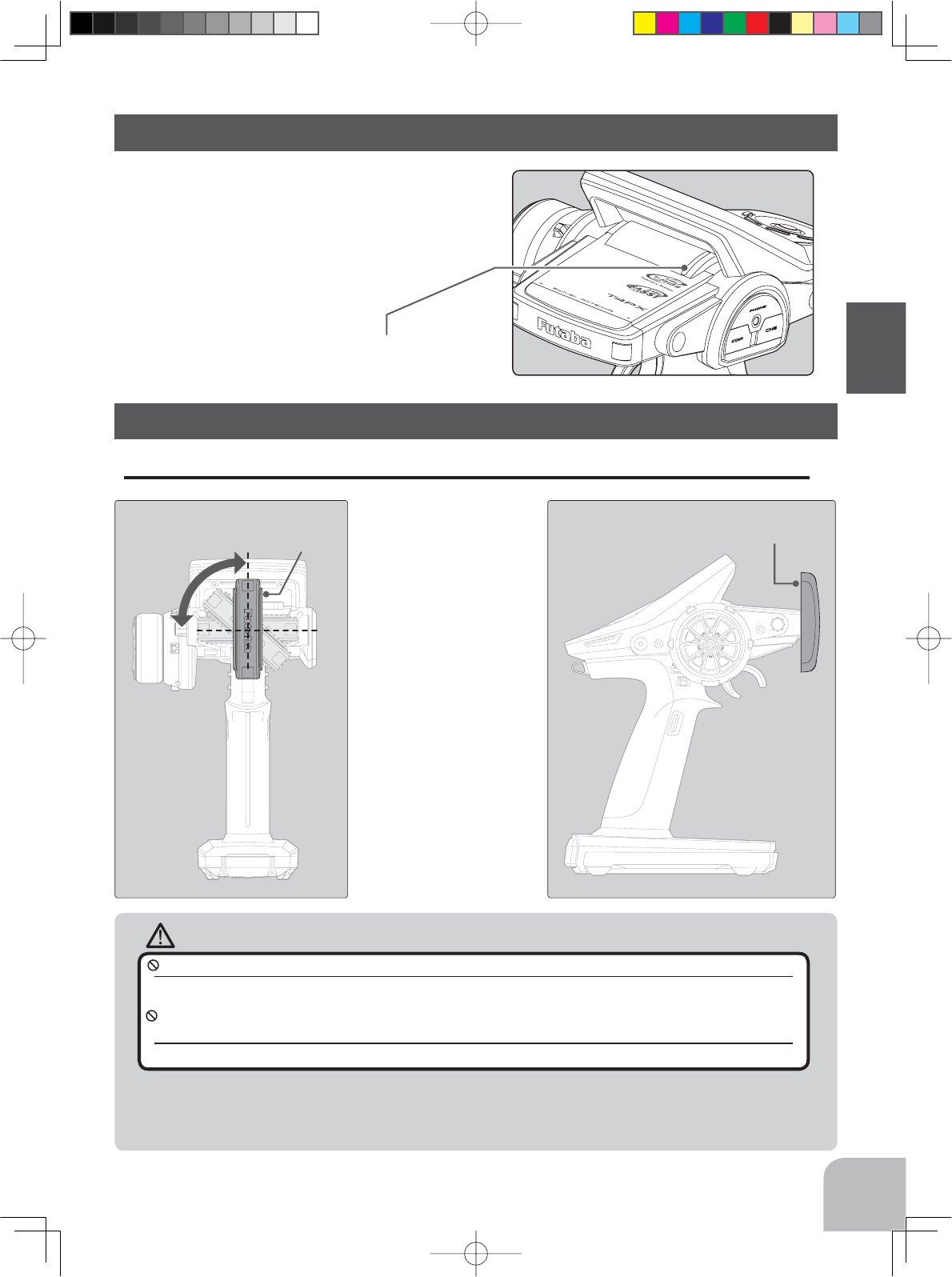
Caution
Cannot rotate more than
90˚.If rotated forcibly, the
antenna will be damaged.
If the antenna is set to the 90˚
vertical position, the range of the
radio waves may be greater than
in the horizontal position. (Different
depending on the conditions)
Antenna
Antenna
Please do not grasp the transmitter's antenna during drive.
Doing so may degrade the quality of the RF transmission to the model.
The antenna position can be changed in the range as shown in figure. However, please do not apply
unnecessary force or shock.
The internal cable may be damaged; thus transmitting distance decreases and it may cause malfunction.
There might be a small glitch when the antenna of the transmitter is brought close to servos,
ESCs or other peripheral devices.
This is not an issue but please keep this symptom in mind, especially when setting-up.
29
Before Using
Antenna Moving Range
Non-telemetry LED (telemetry OFF sign)
Handling the antenna and card slot and receiver
About T4PX Antenna
Non-telemetry LED
(Lit when telemetry function is OFF)
When the telemetry function is inhibited by
race regulations, a special LED lights when
WKHWHOHPHWU\IXQFWLRQLV2))WRFRQ¿UPWKDW
the telemetry function is not operating.
4PX-Eng-04-Before-P12-31.indd 29 2014/07/18 16:59:36
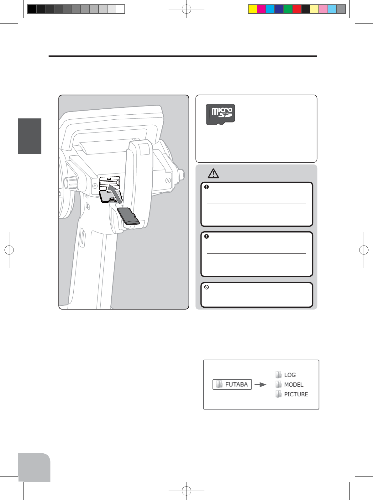
Caution
Insert the card with the metal
terminals side at the bottom.
Remove the card by pushing it
in and then pulling it out.
Install and remove the card by
pushing it in until you hear a
click.
(Commercial product)
SD standard and SDHC standard
microSD cards
*The data in the memory card cannot be guar-
anteed regardless of the contents and cause of
trouble or damage. Always back-up the valuable
data in the memory card.
(Some models may not be oper-
ated by card.)
-When a microSD card is installed in the T4PX transmitter, a folder called "Futaba" is cre-
ated. Folders called "LOG" and "MODEL" are created in this folder. The "MODEL" folder
stores the model data and the "LOG" folder stores
the telemetry log data. When "Save screen" is set
at the push switch by switch setting, an image of
the screen to be displayed on the T4PX is saved
by that switch. The saved image is stored in a
folder call "PICTURE". A "PICTURE" folder is
not created until "Save screen" is set.
-The telemetry log data recorded on the microSD card can be converted to CSV format by
WKHWHOHPHWHUORJFRQYHUWHUUHOHDVHGRQRXUKRPHSDJH:KHQFRS\LQJRUPRYLQJDORJ¿OH
DOZD\VVHOHFWERWK)/,DQG)/'¿OH
30
Before Using
Handling an microSD card (commercial product)
T4PX model data and telemetry log data can be saved by using a commercial microSD
card. When T4PX software updates are released, the microSD card can also be used to
make the update.
Always insert and remove the microSD
card in the state in which the transmitter
power is off.
If the microSD card is removed while being ac-
cessed (read or write), the card itself and the
data may be destroyed.
Since the microSD card is a precision
device, do not subject it to unreason-
able force or shock.
Do not install and remove the microSD
card with the microSD card slot facing
your face.
If you remove your fingers quickly, the microSD
card may fly out and strike your face and is
dangerous.
4PX-Eng-04-Before-P12-31.indd 30 2014/07/18 16:59:36
WARNING
Caution
Antenna
tube
Antenna
Coaxial
cable
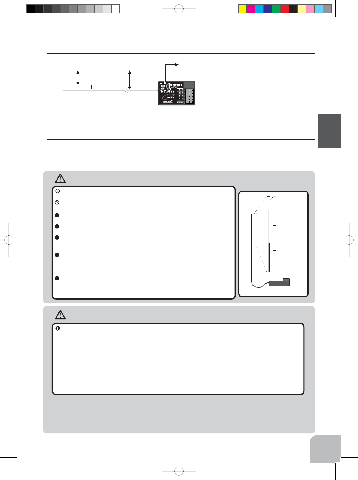
R304SB
Always use R304SB/R304SB-E under the following conditions:
Battery :Power requirement Rated voltage 4.8~7.4V (dry cell battery cannot be used) / 3.5 to 8.4V useable
Matched to the ratings of the receiver and connected servo.
Transmitter’s receiver type :"T-FHSS
Transmitter’s receiver type: Digital servo type :Futaba digital servo
Transmitter’s receiver type: Analog servo type :Futaba all servo
Under other conditions, the set will not operate, or the specified performance will not be displayed even if it operates. In
addition, it may cause trouble with servos and other equipment. Futaba will not be responsible for damage, etc. caused by
combination with the products of other companies.
Receiver Installation
Install the R304SB receiver on the car as follows:
The operating range may become shorter, depending on where the receiver and the antenna
are mounted.
Do not cut or bundle the receiver antenna wire.
Do not bend the coaxial cable. It causes damage.
Install the antenna in the higher place as shown in the figure.
Put the antenna in the antenna tube to protect it.
Keep the antenna as far away from the motor, ESC and other noise
sources as you possibly can.
Wrap the receiver with something soft, such as foam rubber, to avoid
vibration. If there is a chance of getting wet, put the receiver in a water-
proof bag or balloon.
The antenna is installed under the plate (top) of the R304SB-E receiver.
Do not place wiring or other objects on the plate. The receiving range
may be affected.
Transmitter mode setting
Set the transmitter to the "T-FHSS" mode. See page 36 for a description of the setting method.
Note: However, digital servos (including BLS Series brushless servo) can only be used in the "Digital servo type".
Receiver Terminology
Antenna Coaxial cable Tactile switch /LED
Connectors
4 :CH4 servo(CH4)
3 :CH3 servo(CH3)
2 :Throttle servo(CH2)
1 :Steering servo(CH1)
S.BUS2:
Power /S.BUS2 connector
The receiver power supply can be connected
to the S-BUS2 connector or each of CH1-4.
31
Before Using
4PX-Eng-04-Before-P12-31.indd 31 2014/07/18 16:59:37
B/C
CH3
CH2
CH1
CH4
Receiver
Switch
To Battery
CH4 servo
CH3 servo
Throttle servo
Steering servo
#%$
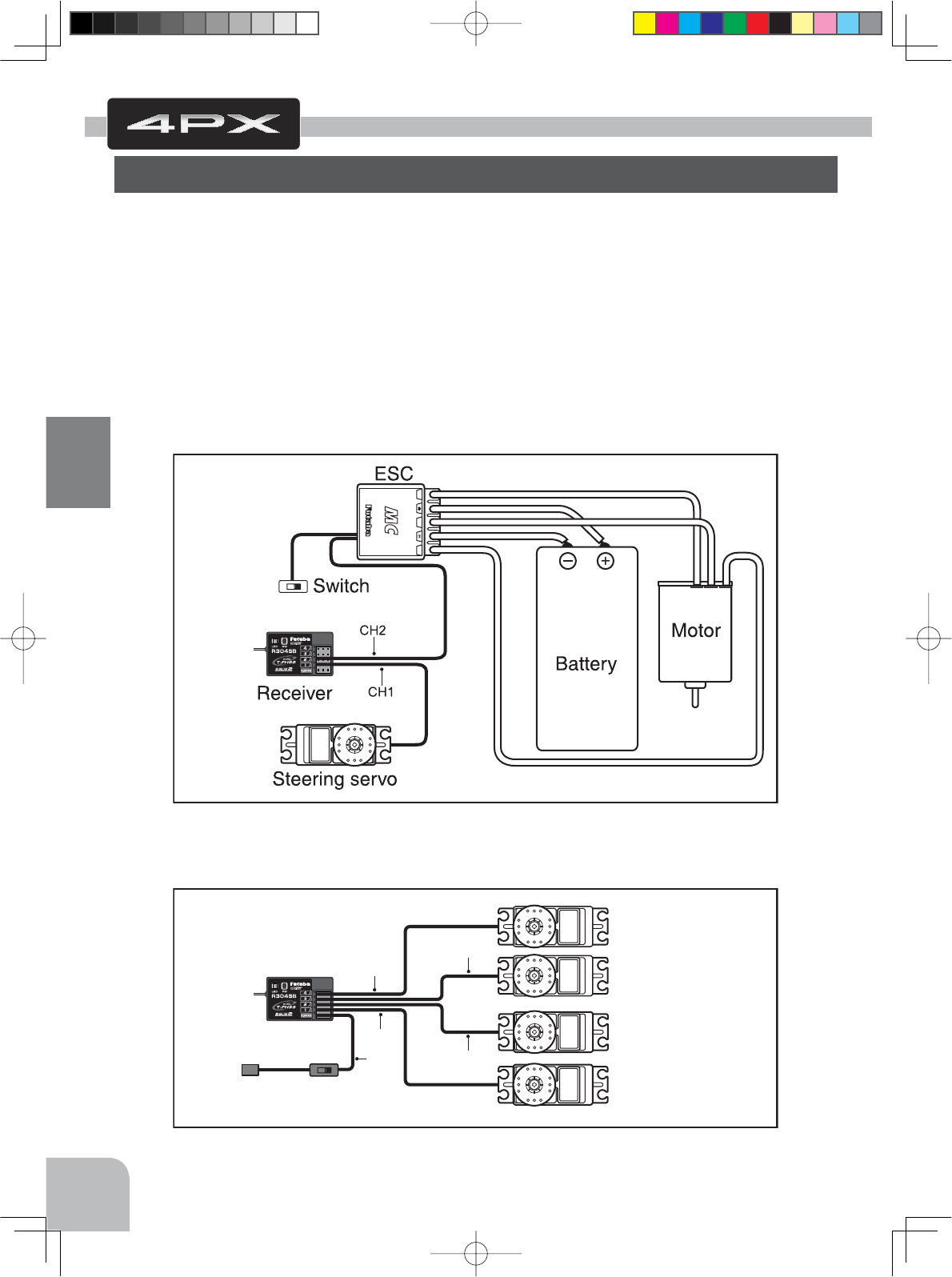
Installation When An Electronic Speed Control Is Used
Installation For Gas Powered Models
32
Installation
Connect the receiver and servos as shown below. Connect and install the receiver and ser-
vos in accordance with "Installation Safety Precautions" on the next page.
7KH¿JXUHVKRZQEHORZLVDQH[DPSOH7KHPHWKRGRIFRQQHFWLQJWKHPRWRUFRQWUROOHUWR
WKHPRWRUDQGEDWWHU\GHSHQGVRQWKHPRWRUFRQWUROOHUXVHG3XUFKDVHWKHPRWRUFRQWUROOHU
and servos separately. The receiver also depends on the set.
When using the DSC cord with a gasoline engine car, connect the optional double extension
cord to B/C of the receiver and the DSC cord and receiver switch to the opposite side con-
nector.
Installation
Receiver And Servo Connections
4PX-Eng-05-Instllation-P32-35.indd 32 2014/07/18 15:52:44
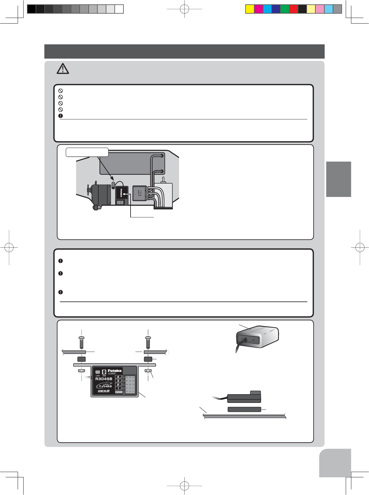
Installation Safety Precautions
Warning
Receiver (receiver antenna)
Receiver Vibration-proofing / Waterproofing
Do not cut or bundle the receiver antenna wire.
Do not bundle the receiver antenna wire together with the motor controller lead wire.
Keep the receiver antenna wire at least 1cm away from motor, battery, and other wiring carrying heavy current.
Do not use a metal receiver antenna holder on a plate made of metal, carbon, or other conductive material.
Install the receiver antenna holder as closely as possible to the receiver.
If the antenna wire is cut, bundled, or routed near a noise source, the receiving sensitivity will drop, the running (cruising)
range will decrease, and you may lose control of the model.
1RLVHLVWUDQVPLWWHGWKURXJKPHWDOFDUERQDQGRWKHUFRQGXFWLYHPDWHULDOVRNHHSWKHUHFHLYHUDQWHQQDZLUHDZD\IURPVXFKSDUWV
(Car)
Vibration-proof the receiver by wrapping it in foam rubber or other vibration-absorbing material and mount it with
thick double-sided tape.
When using the receiver holder supplied with the model kit, mount the holder to the chassis through a rubber
grommet.
(Boat)
Vibration-proof the receiver by wrapping it in foam rubber or other vibration-absorbing material. Also waterproof
the receiver by cruising it in a plastic bag.
If the receiver is exposed to strong vibration and shock, it will operate erroneously due to the invasion of water drops and
you may lose control of the model.
Screw
Mechanical plate
Nut (as required)
Receiver holder
Damper
When using the receiver holder sup-
SOLHGZLWKWKHNLWLQVWDOOWKHUHFHLYHU
WKURXJKDUXEEHUJURPPHW
Foam rubber, etc.
:UDSWKHUHFHLYHULQIRDPUXEEHURURWKHU
YLEUDWLRQDEVRUELQJPDWHULDO'R QRW XVH
KDUGPDWHULDO+DUGPDWHULDOGRHVQRW
KDYHDYLEUDWLRQSURR¿QJHIIHFW
Mechanical plate Thick double-
sided tape
:KHQ PRXQWLQJ WKH UHFHLYHU ZLWK GRXEOHVLGHG WDSH
do not use a stiff tape. Stiff tape does not have a vibra-
WLRQSURR¿QJHIIHFW
#%$
Antenna
,QVWDOO WKH UHFHLYHU DV IDU DZD\ DV SRVVLEOH IURP WKH
EDWWHU\PRWRUFRQWUROOHUPRWRUVLOLFRQFRUGDQG
RWKHU QRLVH VRXUFHV .HHS LW DZD\ IURP WKH DQWHQQD
wire, in particular.
Since the antenna of built-in antenna receivers is installed
under this, do not place wiring or other objects on it.
Battery
33
Installation
4PX-Eng-05-Instllation-P32-35.indd 33 2014/07/18 15:52:45
Warning
Connector Connections
Servo Installation
Be sure the receiver, servo, battery and connectors are fully and firmly connected.
If vibration from the model causes a connector to work loose while the model is in operation, you may lose control .
When you install the servos, always use the rubber grommets provided in servo hardware bags. Mount the
servos so they do not directly come in contact with the mount.
If the servo case comes in direct contact with the mount, vibration will be directly transmitted to the servo.
If this condition continues for a long time, the servo may be damaged and control will be lost.
Servo Throw
Operate each servo over its full stroke and be sure the linkage does not bind or is loose.
The continuous application of unreasonable force to a servo may cause damage and excessive battery drain.
Screw
Mechanical plate
Nut (as required)
Eyelet
Damper
(or)
When installing the servo, always install the accessory
UXEEHUJURPPHWDQGJURPPHWÀXVKDJDLQVWWKHVHUYR
$YLEUDWLRQGDPSLQJHIIHFWLVQRWREWDLQHGHYHQ
LIWKHUXEEHUJURPPHWDQGJURPPHWDUHQRWLQ-
stalled correctly.
Adjust the throttle servo so that unreasonable force is
not applied when the engine carburetor is fully open,
IXOO\FORVHGDQGWKHEUDNHVDUHDSSOLHGIXOO\
,IWKHEUDNHVRYHUKHDWZKLOHUXQQLQJWKHLUDELOLW\WR
function properly decreases. Before running, adjust the
VXLWDEOHPD[LPXPVHUYRWUDYHOVRWKDWXQUHDVRQDEOH
force is not applied even when the servo travel is in-
creased while running.
Adjust the steering servo so that unreason-
able force is not applied to the servo by the
FKDVVLVDWPD[LPXPVHUYRWUDYHO
Decide the EPA value at the
contact point.
Caution!
A whining noise indicates that the
steering servo is improperly set.
34
Installation
4PX-Eng-05-Instllation-P32-35.indd 34 2014/07/18 15:52:46
Warning
Electronic Speed Cont
Motor Noise Suppression
Install the heat sinks where they will not come in contact with aluminum, carbon fiber or other parts that conduct
electricity.
If the FET Amp (Electronic speed control) heat sinks touch other materials that conduct electricity a short circuit could oc-
cur. This could result in loss of control and damage to the system.
Always install capacitors to suppress noise when electric motors are used.
If capacitors are not properly installed you could experience erratic operation and reduced range as well as loss of control.
Other Noise Suppression Methods
Be sure there are no metal parts in your model which under vibration can come in contact with other metal parts.
Metal to metal contacts under vibration will emit a high frequency noise that will affect the receiver's performance. You
could experience erratic operation and reduced range as well as loss of control.
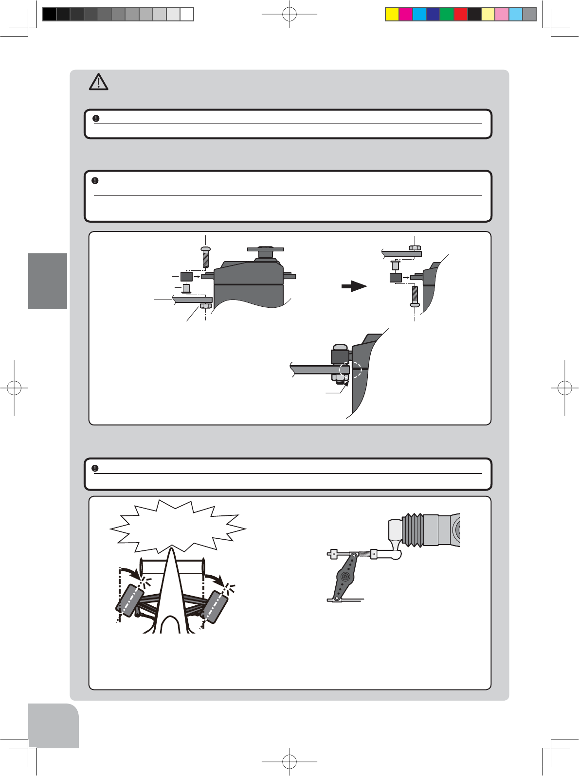
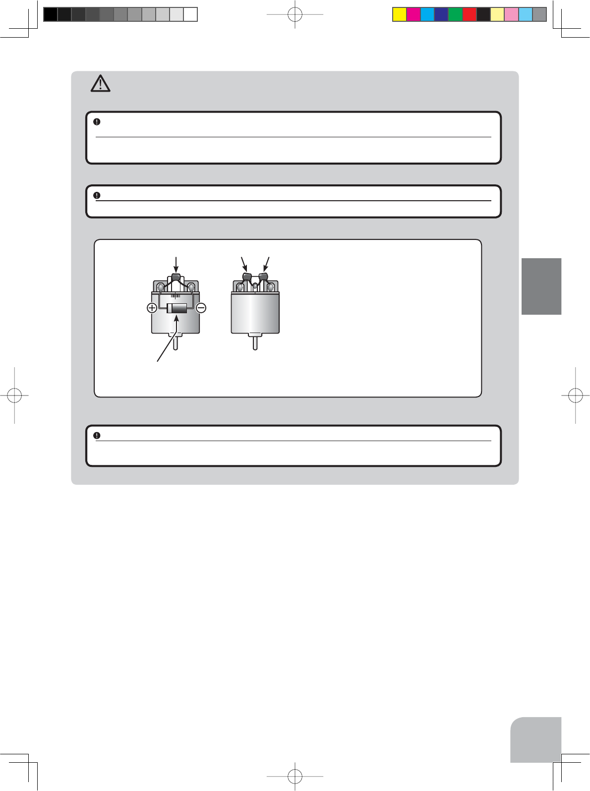
Motors with no suppressor capacitors, or inade-
TXDWHVXSSUHVVLRQPD\FDXVHWKHUHFHLYHUWRPDO-
function. Always solder the capacitors supplied to
\RXUPRWRU
7KH6FKRWWN\GLRGHLPSURYHVWKHHI¿FLHQF\RIWKH
VSHHG FRQWURO PRWRU FRPELQDWLRQ DQG SURYLGHV
H[WUDSURWHFWLRQWRWKHEUDNH)(7V7KHZKLWHULQJ
PXVWDOZD\VIDFHWKHSRVLWLYHVLGH
Schottky diode
"-" side
"+" side
123
35
Installation
4PX-Eng-05-Instllation-P32-35.indd 35 2014/07/18 15:52:46
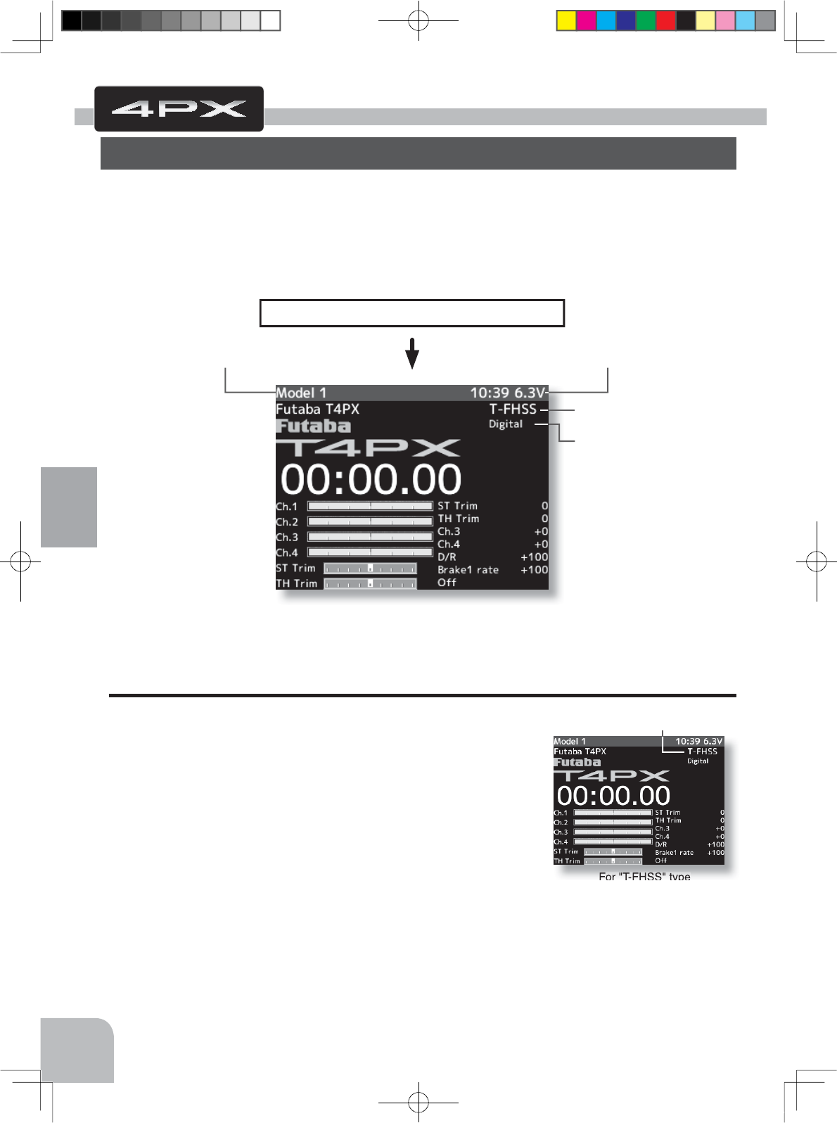
For "T-FHSS" type
"T-FHSS" is displayed
36
Initial Set-Up
Before setting up each function of the transmitter, check and set the following items.
RF Output & Rx Type Check
Check if the receiver type is set to the type of receiver used.
*When the "PWR" side power switch is set to ON and radio
waves are output normally, "T-FHSS", "S-FHSS", or "FASST" is
displayed. If not displayed, there is probably an abnormality or
trouble so contact a Futaba Service Center.
When a screen is displayed at the "DSP" side, "Display" is dis-
played.
*Since the R304SB receiver supplied with the T4PX set uses the
telemetry function T-FHSS system, T4PX receiver setup must be
set to T-FHSS.
The R2104GF and other S-FHSS and FASST system receivers, as well as the R304SB T-
FHSS system receiver can be used with the T4PX transmitter. However, only R614FS/FS/
FF-E and R604FS/FS-E "C2" type receivers can be used with the FASST system.
The R603FS/FF "C1" type cannot be used.
Receiver type check
Seervo type check
Voltage check
Initial Set-Up
Preparations (Transmitter)
(Display when power switch turned on)
When the power switch is turned on, the currently selected model number is displayed.
Check if this number is the model number you want to set-up. To change the model number,
use the Model Select function. (p.112)
(HOME screen)
Turn on the transmitter power.
The model number is displayed.
4PX-Eng-06-Inst_set-36-41.indd 36 2014/07/18 16:58:44
Receiver screen
HOME screen
MENU 1 screen
Pres
s
Pres
s
Pres
s
37
Initial Set-Up
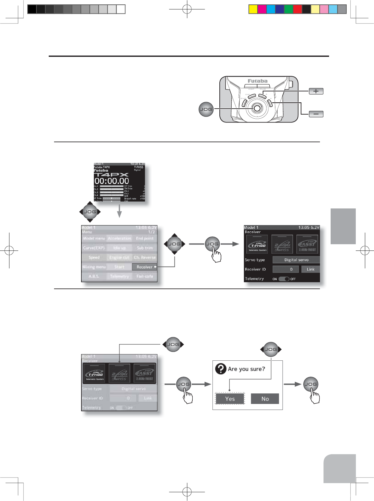
Receiver Type Change & How To Link
)LUVW VHW XS WKH UHFHLYHU 6HWWLQJ FKDQJHV DUH LPPHGLDWHO\ UHÀHFWHG 1H[W WKH WUDQVPLWWHU
and receiver are linked and the receiver memorizes the transmitter ID number so that sig-
nals from other transmitters will not be received.
In addition, with the T-FHSS telemetry system,
the transmitter simultaneously memorizes the
receiver ID numbers so that data from other re-
ceivers will not be received.
The method of setting up the receiver type and the method of linking the transmitter and
UHFHLYHUDUHGHVFULEHG5HIHUWRWKH¿JXUHDWWKHULJKWIRUWKHHGLWEXWWRQVXVHG
1Set the transmitter "PWR" side power switch to ON.
Display the menu 1 screen by (JOG) button up, down,
left, or right operation at the home screen. Select "Re-
ceiver setup" by (JOG) button up, down, left, or right
operation and display the "Receiver setup" screen by
pressing the (JOG) button.
2Select the receiver type to be changed by (JOG) button left or right operation. When the (JOG)
button is pressed, a confirmation screen is displayed. To execute the change, select "YES"
by JOG button. When the JOG button is pressed for about 1 second, an electronic beeping
sound is generated and setting is ended. To cancel the change, select "No" and press the
(JOG) button.
*After set up this far is complete, when using a FASST system (R614FS/FF/FF-E) or S-
FHSS system (R2104GF, R204GF-E, etc.) receiver, go to "Receiver other than T-FHSS" on
P39. When using a telemetry function T-FHSS receiver (R304SB, etc.), go to step
4PX-Eng-06-Inst_set-36-41.indd 37 2014/07/18 16:58:46
Link failedLink established
R304SB
The link is completed. Repeat the linking operation
Pres
s
Pres
s
Pres
s
38
Initial Set-Up
3Bring the transmitter and receiver within 50cm of each other (antennas do not touch) and
turn on the receiver power.
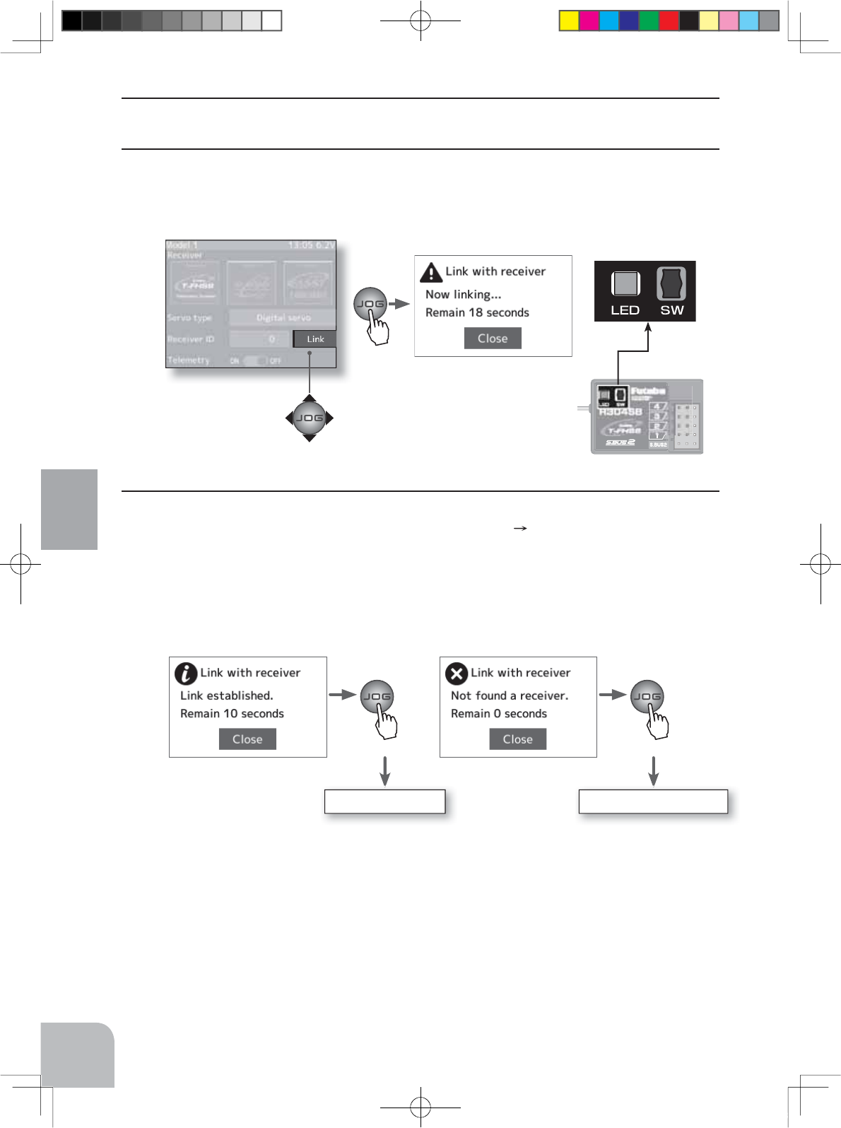
4Move the cursor to "Link" by T4PX transmitter (JOG) button up or down operation. When
the (JOG) button is pressed, a chime will sound and the T4PX will enter the link mode for
20 seconds. During this 20 seconds link mode, press the receiver tactile switch for at least 2
seconds.
5During the 20 seconds link mode, press the receiver tactile switch for at least 2 seconds.
The LED blinks red and then changes to a greenish red green steady light. When the
T4PX makes a beeping sound and the message "Link with receiver" appears on the screen,
release the receiver tactile switch. This ends reading of mutual ID and displays the memo-
rized receiver ID number on the T4PX screen. If the "Receiver not found" error screen is dis-
played, linking failed. Check the set contents and repeat the linking operation.
*The T4PX and a telemetry system T-FHSS receiver (R304SB, etc.) memorize the IDs linked
last at each model memory. Since only one receiver ID is memorized at each model mem-
ory, multiple T-FHSS receivers cannot be used with the same model memory. When a re-
ceiver at the same model memory is changed, re-linking is necessary even if the receiver is
already linked with the transmitter.
When using multiple T-FHSS telemetry receivers, link each receiver with each T4PX model
memory. However, one receiver can be linked with multiple model memories. The telemetry
function communication status can be checked at the T4PX home screen.
4PX-Eng-06-Inst_set-36-41.indd 38 2014/07/18 16:58:46
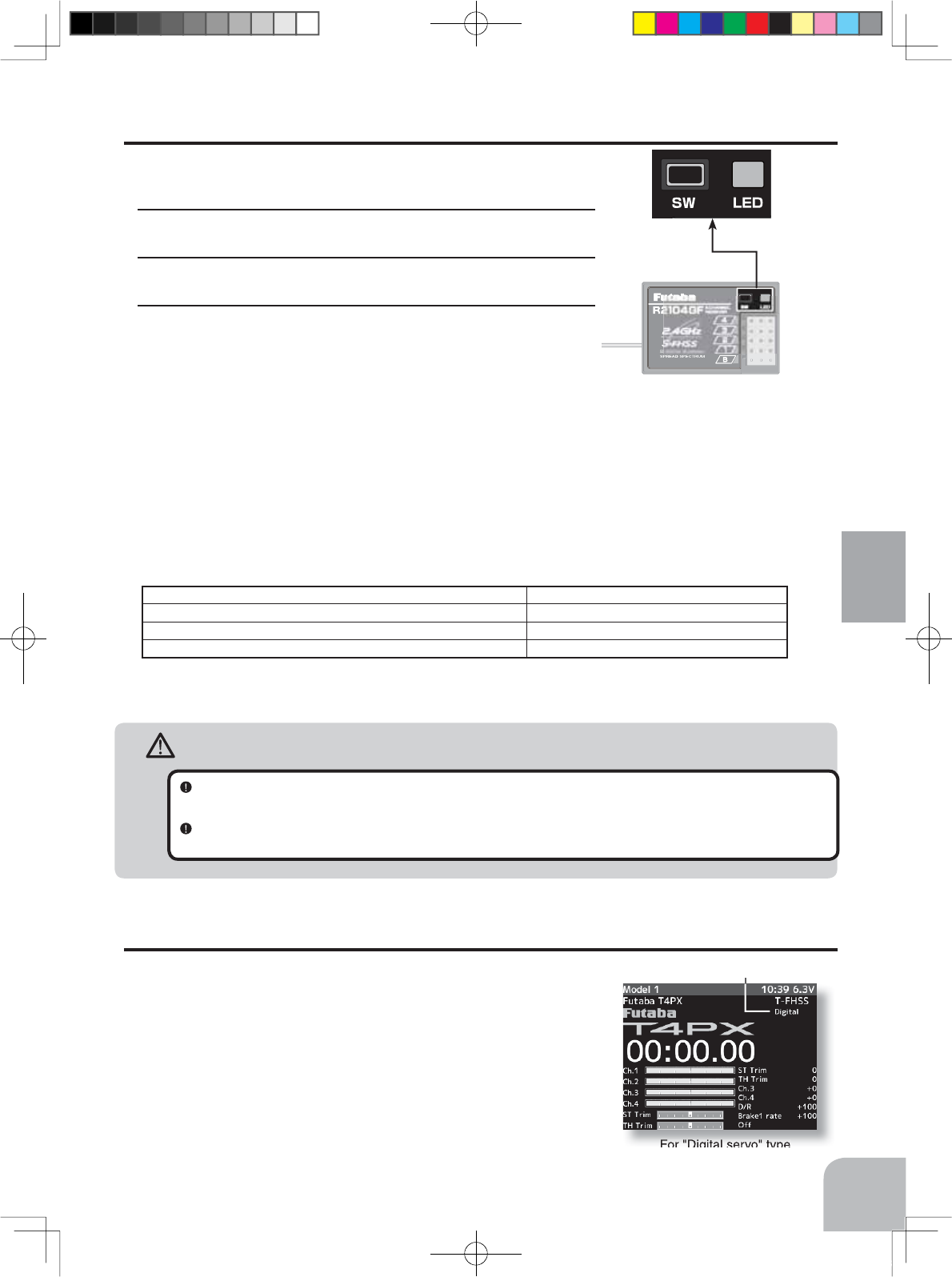
For "Digital servo" type
"Digital" is displayed
Receivers Other Than T-FHSS
1Bring the transmitter and the receiver close to each other,
within 20 inches (half meter).
2Turn on the transmitter.
3Turn on the receiver.
4Push the tactile switch of the receiver.
When the link is complete, the LED in the receiver changes
to solid green.
Precaution:
If there are many Futaba 2.4GHz systems (T-FHSS/ S-FHSS/ FHSS) turned on in close proximity to your receiver
might not link to your transmitter. In this case, even if the receiver’s LED stays solid green, unfortunately the receiv-
er might have established a link to one of other transmitters. This is very dangerous if you do not notice this situa-
tion. In order to avoid the problem, we strongly recommend you to double-check whether your receiver is really un-
der control by your transmitter by giving the stick input and then checking the servo response.
*Please refer to the table below for LED status vs receiver's condition.
LED status vs receiver’s condition:
Warning
After the linking is done, please cycle receiver power and check if the receiver to be linked is really under the
control of your transmitter.
Do not perform the linking procedure with motor’s main wire connected or the engine operating as it may result in
serious injury.
No signal reception Red : On
Receiving signals Green: On
Receiving signals, but ID is unmatched. Green: Blink *1 (T-FHSS ,Red : On)
Unrecoverable failure (EEPROM,etc.) LED: Red and Green turn on alternately
*1: LED could be change to red during intermittently during data processing.
39
Initial Set-Up
Servo Type Check
Check if the servo type setting matches the servo used. When
a digital servo (including BLS brushless servo) is used, "Digi-
tal servo" or "Analog servo"" can be set. Since an analog servo
cannot be used with the "Digital servo" setting, the servo type
must be set to "Analog servo". If used with the wrong setting,
the analog servo will be damaged. If the setting is incorrect,
change it by the following method.
4PX-Eng-06-Inst_set-36-41.indd 39 2014/07/18 16:58:48
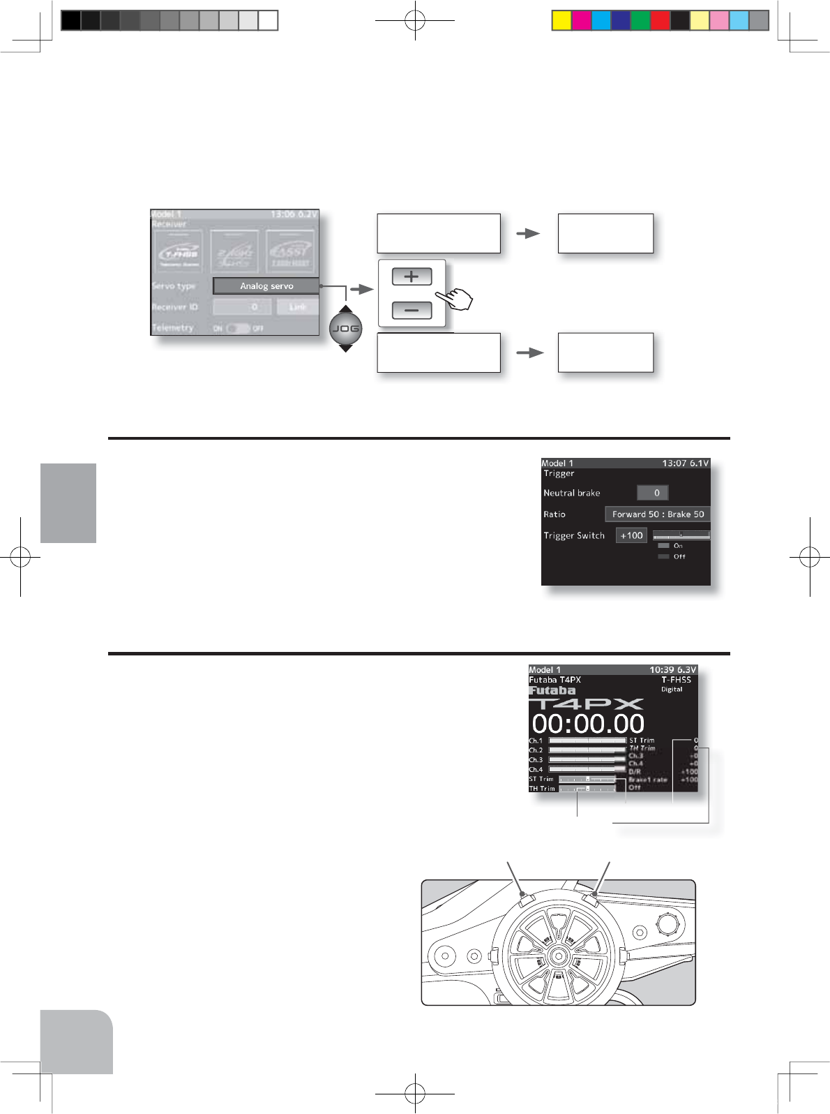
Receiver screen
From a digital servo to
an analog servo
Changes to an
analog servo
Changes to a
digital servo
From an analog servo
to a digital servo
or
Throttle trim (DT2) Steering trim (DT1)
Steering trim
Throttle trim
Pres
s
40
Initial Set-Up
Trigger mode screen
Trigger Ratio Check
-The throttle servo travel can be set to 50:50, 70:30 or 100:0 for
throttle trigger operation as required by the Trigger mode func-
tion (p.66).
-The throttle brake operation might be a close by setting it to
"100:0" when the T4PX transmitter with the boat is used.
Refer to page 36 and display the "Receiver setup" screen. Move the cursor to the servo type
by (JOG) button up or down operation. Changes when "Digital servo" or "Analog servo" is
selected by pressing the (+) or (-) button.
Trims Initial Set-Up
- Steering trim (DT1) check
On the initial set-up, steering trim is assigned to the DT1
trim lever above. Operate the lever and make sure the marker
moves on the ST graph. If default has been changed, test
steering trim in its new location. After checking the trim, set
the trim display to the center (N) position.
- Throttle trim (DT2) check
On the initial set-up, throttle trim is assigned
to the DT2 trim lever. Operate the lever
and make sure the marker moves on the TH
graph. If the default has been changed, test
the throttle trim in its new location. After
checking the trim, set the trim display to the
center (N) position.
4PX-Eng-06-Inst_set-36-41.indd 40 2014/07/18 16:58:48
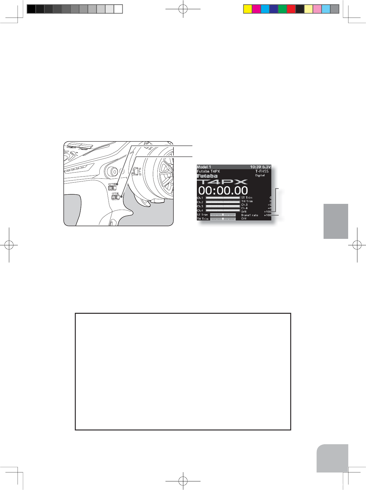
Brake rate
Steering dual rate
Steering dual rate DT5
Brake rate (Brake1) DT6
41
Initial Set-Up
- Steering dual rate (DT5) check
At initial set-up, steering dual rate (D/R) is assigned to DT5 trim lever, at the grip of the
transmitter. Operate the DT5 and check if the D/R value displayed on the screen changes.
After checking D/R, set the steering dual rate to 100%.
- Brake rate (DT6) check
At initial setting, brake rate (Brake1 rate) is assigned to DT6 trim lever, below DT6. Operate
the DT6 and check if the Brake1 rate value displayed on the screen changes. After checking
Brake1 rate, set brake rate to 100%.
(Set-Up Procedure When Installed In a Car)
When installing the servos in a car, performing function set-up in the following order is
recommended.
1 Initialize all the trims.
2Set the servo direction of operation using the Reverse function. (p.47)
- The servo installation method and linkage direction depend on the kit. Therefore, the servo
operation direction may have to be reversed relative to transmitter operation. Before install-
ing the servo, check the operating direction and set it using the Reverse function.
3Set the subtrim and adjust the servo neutral point. (p.48)
4Set the trigger travel by adjusting the throttle trigger mechanical ATL to
your liking. (p.18)
- When the stroke was adjusted, compensate the throttle by adjuster function (p.152).
5
Set EPA of each channel and adjust the servo throw (travel). (
p.49
)
4PX-Eng-06-Inst_set-36-41.indd 41 2014/07/18 16:58:49
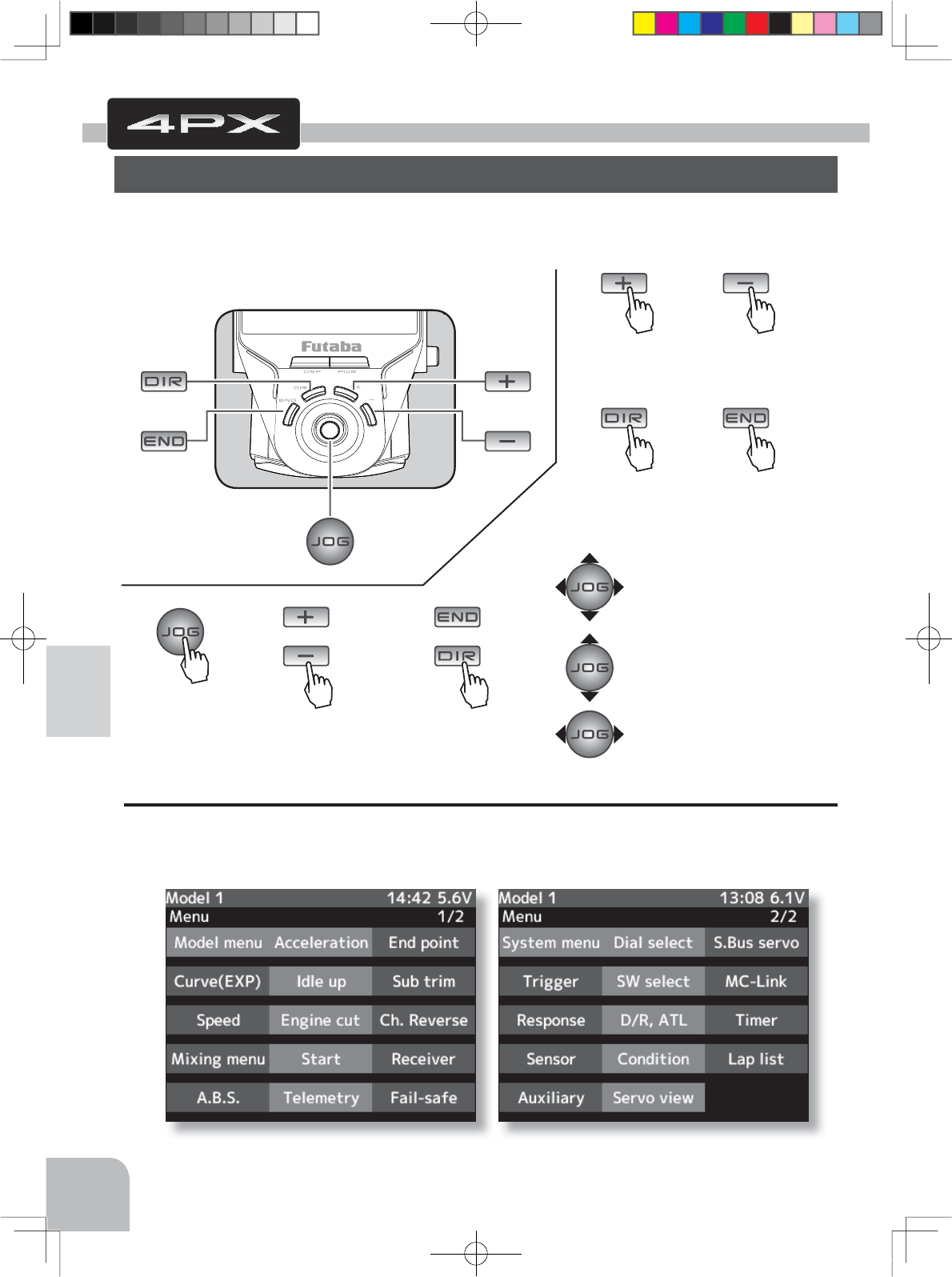
(+) button is press
(DIR) button is
press
(-) button is press
(END) button is
press
(JOG) button is press
(JOG)button up, down, left or right
(JOG)button up or down
(JOG)button left or right
Edit Buttons
(END) or (DIR) button
is press
(+) or (-) button is press
Pres
s
or or
Pres
s
Pres
s
Pres
s
Pres
s
Pres
s
Pres
s
42
Function Map
In this instruction manual, Edit Buttons are represented by the symbols shown below.
The (JOG) button can be operated in the 4 directions up, down, left, and right.
Calling The Menu Screen
The menu screen consists of 2 pages designated menu 1 and menu 2, and can display up to
29 setting items. Refer to the map on the next page for a description of the menu screen and
setup screen display method.
Function Map
Menu Selection
(MENU 2 screen)(MENU 1 screen)
4PX-Eng-07-Menu-42-45.indd 42 2014/07/18 17:08:27
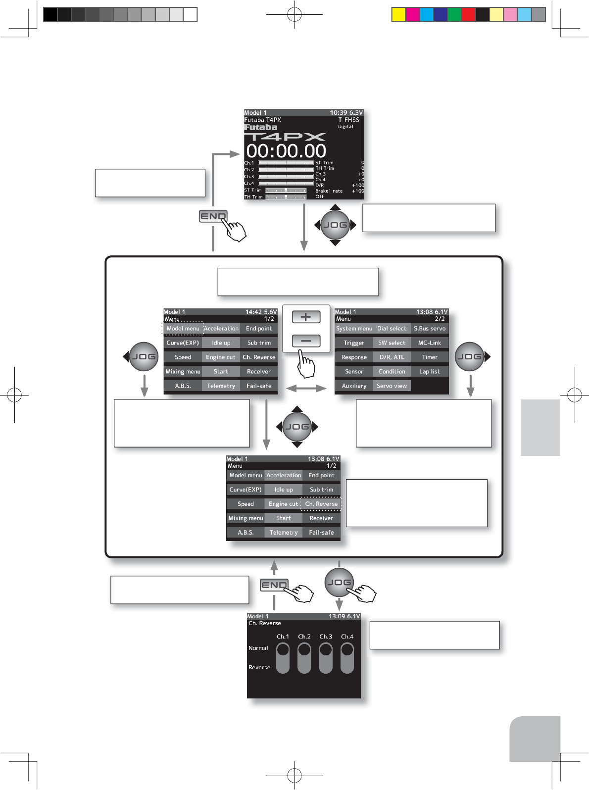
Press the (END) button to
return to the HOME Screen.
(HOME screen)
(Function Set-up Screen)
Call the menu screen by (JOG)
up, down, left, or right operation.
Call the setup screen by pressing
the (JOG) button.
Press the (END) button to return to
the MENU Screen.
On the menu screen, select the
function by moving the cursor by
(JOG) button up, down, left, or right
operation.
When the cursor is at the right end
of the screen and (JOG) button
right operation is performed, the
display switches to menu 1.
When the cursor is at the left end
of the screen and (JOG) button
right operation is performed, the
display switches to menu 2.
Switch MENU1 and MENU2 by pressing
the (+) or (-) button.
or
Pres
s
* The screen on the right shows
an example of setting "Ch.Re-
verse" function.
Pres
s
Pres
s
Pres
s
43
Function Map
Selecting Items On The Menu Screen
(MENU 2 screen)(MENU 1 screen)
4PX-Eng-07-Menu-42-45.indd 43 2014/07/18 17:08:27
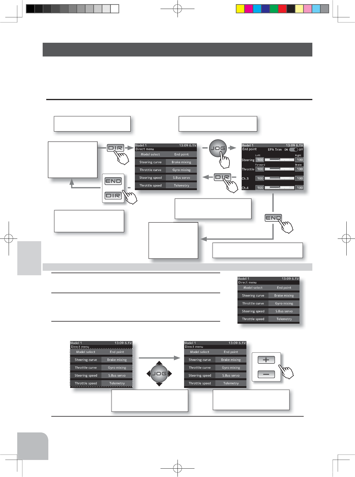
All screens,
including the
home screen
It returns to the previous
screen with (END) or (DIR)
button
Select the setting location by
(JOG) button up, down, left, or
right operation.
Select the function to be as-
signed by (+) or (-) button.
or
or
Pres
s
Call the direct menu screen by
pressing the (JOG) button.
Press the (DIR) button to return
to the MENU Screen.
Press the (END) button to return to the
HOME Screen.
Call the setup screen by pressing
the (JOG) button.
HOME screen
(Function Set-up Screen)(Direct menu Screen)
(Direct menu Screen)
Pres
s
Pres
s
Pres
s
Pres
s
Pres
s
44
Function Map
Direct Menu
With the T4PX, setting items often used can be registered as up to 10 direct menus. A dif-
ferent direct menu can be created for each model memory. The direct menus can also be
copied to other models by model copy function. (p.114)
Displaying the direct menu screens
The direct menu screens can be displayed by pressing the (DIR) button from any screen.
1Call the direct menu screen by pressing the (DIR) button.
2Move the cursor and select the location to be assigned a
function by (JOG) button up, down, left, or right operation.
3Select the function to be assigned by (+) or (-) button.
Menu assignment
4
When assignment is complete, return to the direct menu screen by pressing the (DIR) button.
4PX-Eng-07-Menu-42-45.indd 44 2014/07/18 17:08:28
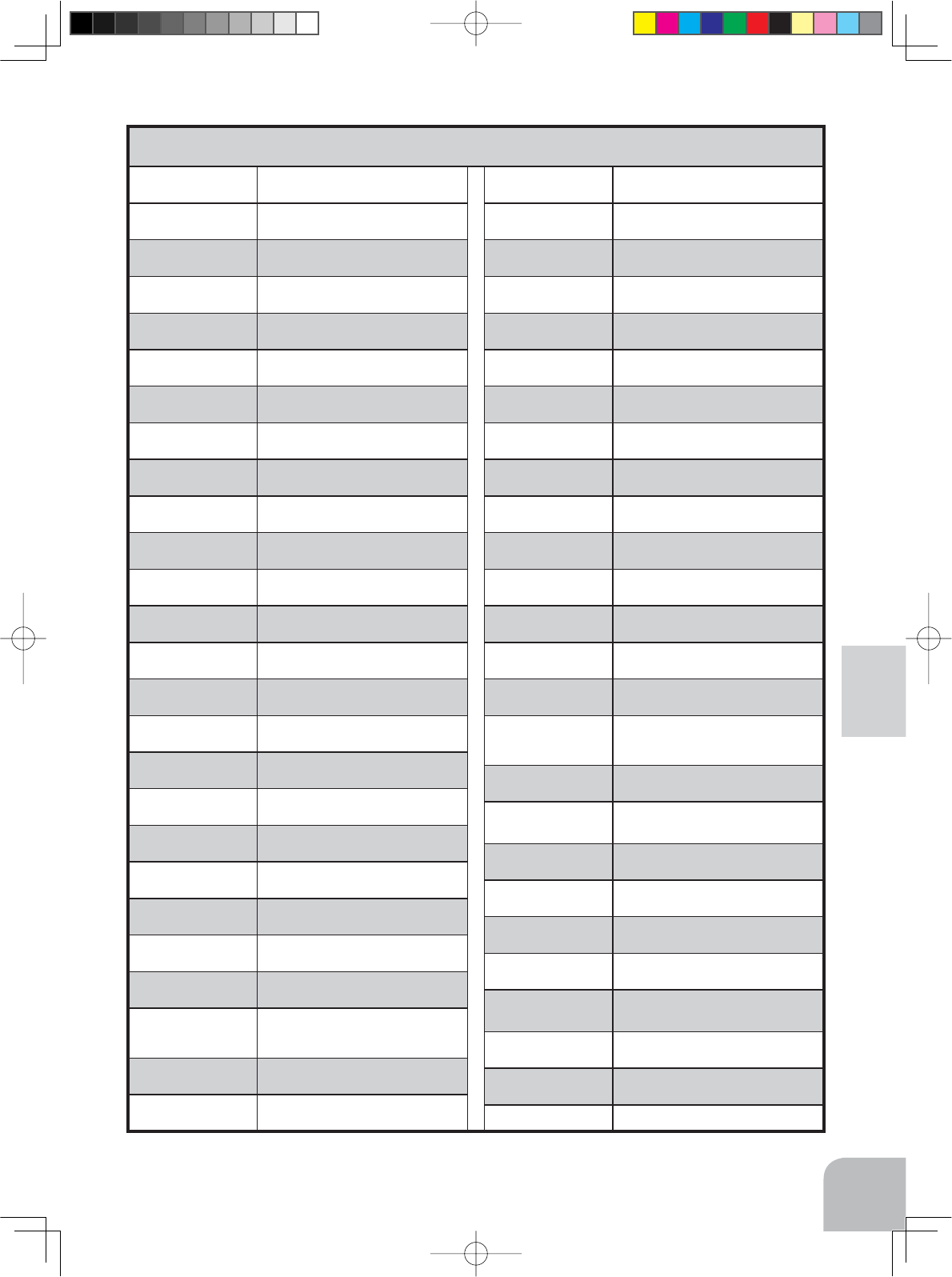
45
Function Map
Function Name Description Of Function
Model select Model memory call
Model copoy Model memory copy
LED setting LED on/off, jog LED on/off
S.BUS servo S.BUS servo Link software setting
Sensor
Telemetry sensors setting
Sensor list Telemetry sensors list
Telemetry
Telemetry data screen
MC-Link MC851C/602C/402CR/950CR/940CR
/960CR Link software setting function
Condition 2ND condition
User name User name set/modify
Battery Battery type setting
Date and time Date and time setting
Calibration Steering wheel and throttle trigger cor-
rection
Display LCD contrast/backlight setting
End point End point adjustment
Fail safe Fail safe, battery fail safe
Information Language setting / version information
Model name Model memory name set/modify
Data reset Model memory reset (Model, Direct
menu, All)
Ch. Reverse Servo operation reversing
Sound Sound setting (telemetry sound, alarm
sound, operating sound)
Sub Trim 6HUYRFHQWHUSRVLWLRQ¿QHDGMXVWPHQW
Receiver
Receiver type/servo tyoe selection/
linking with telemetry type T-FHSS
system receiver
Response etting of the response
Auxiliary Channel 3&4 servos operation posi-
tion set/check
Function Description Of Function
Servo view Displays servo operation on a bar
graph
D/R,ATL Steering angle adjustment while run-
ning/ Brake side adjustment
Dial select Selection of functions operated by
digital dial and digital trim
SW select Selection of functions operated by
push switches
Acceleration Reduces the "lag time" of the throttle
from the neutral position.
Steering curve
Steering curve adjustment
Throttle curve Throttle curve adjustment
Steering speed
Steering servo delay
Throttle
speed
Throttle servo delay
Start Throttle preset at start function
Engine cut engine cut off by switch
A.B.S Pumping brake
Brake mixing Front and rear independent brake con-
trol for 1/5GP car, etc.
Tilt mixing Outboard engine tilt mixing
Trigger
Neutral brake and throttle servo for-
ward side and brake side operation
rate setting/Trigger SW
Idle up Idle up at engine start
Program.
mixing 1-5
Programmable mixing between arbi-
trary channels
4WS mixing 4WS mixing
Dual ESC Front and rear ESCs mixing
Gyro mixing The sensitivity of Futaba car rate gy-
ros can be adjusted
CPS mixing The CPS-1 of Futaba LED controller
can be adjusted.
Steering
mixing Twin servo mixing of the steering
Timer Up, down, lap, or lap navigation timer
Lap list Lap timer data (lap time, average lap,
best lap time) check
-------
Function List
4PX-Eng-07-Menu-42-45.indd 45 2014/07/18 17:08:28
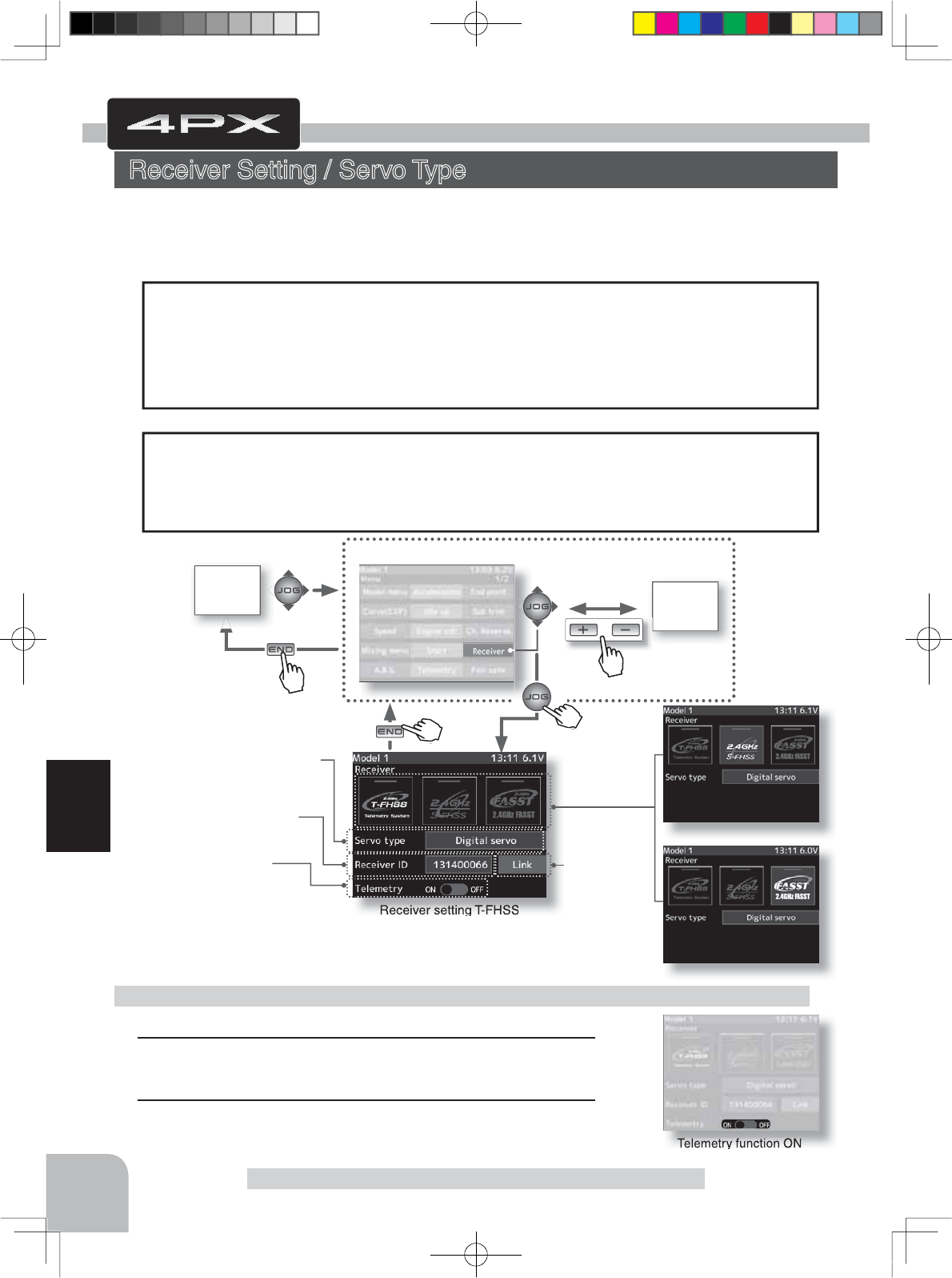
Telemetry function ON
Receiver setting T-FHSS
Receiver setting S-FHSS
Receiver setting FASST
HOME
screen MENU 2
screen
or
MENU 1 screen
Pres
s
Pres
s
Receiver setting
T-FHSS
S-FHSS
FASST
Servo type setting
Analog servo
Digital servo
T-FHSS Receiver ID
Telemetry function
ON/OFF
Link
Only T-FHSS
Pres
s
Pres
s
Pre
Pres
s
46
Function
Select telemetry by (JOG) button operation.
1 (Function ON/OFF)
Select the type and ON/OFF by (+) or (-) button.
2When ending, return to the menu screen by pressing the
(END) button.
Telemetry function ON/OFF
Receiver Setting /Servo Type
This menu selects the settings matched to the receiver system used and the type of servo
and the items selected at the T4PX, linking of the T4PX with the T-FHSS telemetry system,
and ON/OFF.
The receiver setting and selection and linking of the T4PX transmitter with a T-FHSS telemetry
system receiver are described on P36~39. Please read them.
Function
Receiver Setting / Servo Type
Receiver
The T4PX transmitter can use the S-FHSS and FASST system receivers, as well as the
R304SB T-FHSS system receiver supplied. However, only the "C2" type (R614FS/FF/FF-
E,etc) receivers can be used with the FASST system. The R603FS/FF "C1" type receiver
does not operate. Make your selection by matching to the system of the receiver to be used.
The model data remains unchanged even if the receiver setting is changed.
"
Digital servo type" or "Analog servo type" servo type can be selected. However, the
"Digital servo type" is for Futaba digital servos (including BLS Series brushless servos)
use only. When using other servos, select the "Analog servo type". All servos, including
digital servos, can be used in the "Analog servo type".
Servos
4PX-Eng-08-Function-46-65.indd 46 2014/07/18 17:14:47
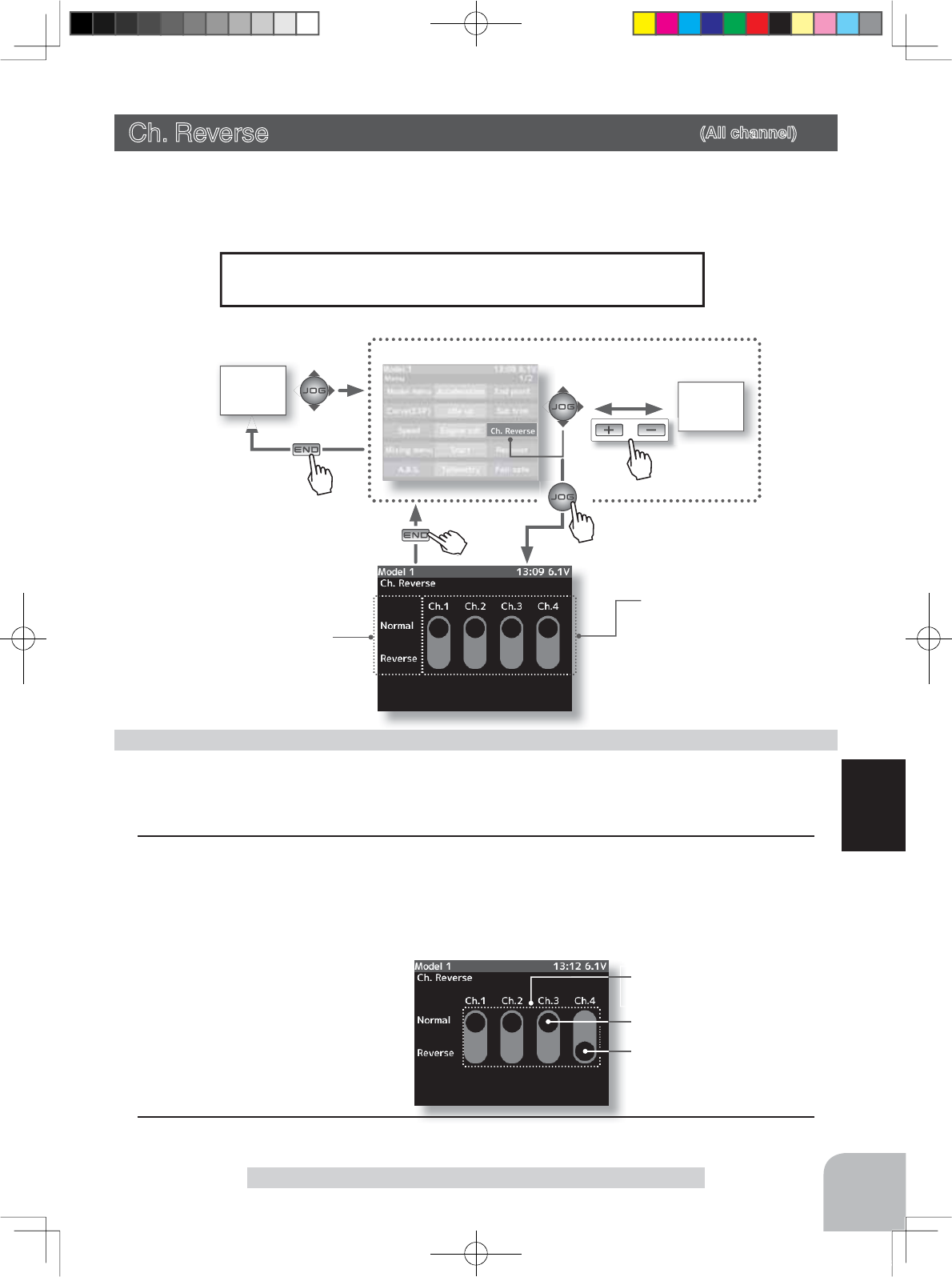
HOME
screen MENU 2
screen
or
MENU 1 screen
Pres
s
Pres
s
Pres
s
The switch mark of the current
channel is displayed in blue.
Normal side
Reverse side
Channel
Ch1 :Steering
Ch2 :Throttle
Ch3 :Channel3
Ch4 :Channel4
Reverse setting
Normal/Reverse
Channel selection
- Select by (JOG) button left or
right operation.
Select button
- Select with the (+) or (-) but-
tons.
Pre
Pres
s
47
Function
Ch. Reverse
However, when the position set by trim or subtrim shifts from
the center, the center becomes the opposite side.
Ch. Reverse (All channel)
This function reverses the direction of operation of the servos related to transmitter
steering, throttle, channel 3, and channel 4 operation.
(Preparation)
Select the channel to be set by (JOG) button left or right operation.
1(Servo reverse setting)
Use the (+) or (-) button to reverse the servo operation
direction.
(Each channel can be set similarly.)
Servo Reverse Function Setting
2When ending setting, return to the menu screen by pressing the (END) button.
4PX-Eng-08-Function-46-65.indd 47 2014/07/18 17:14:48
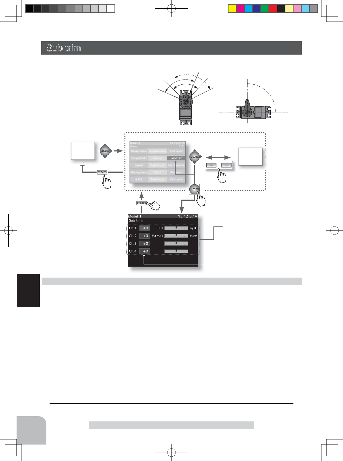
HOME
screen MENU 2
screen
or
MENU 1 screen
The rate of the current channel
is displayed in blue.
Pres
s
Pres
s
Pres
s
Channel
Ch1 :Steering
Ch2 :Throttle
Ch3 :Channel3
Ch4 :Channel4
Pre
Pres
s
48
Function
Subtrim
90deg
Use this function to adjust the neutral position of the steering, throttle, channel 3 and
channel 4 servos.
(Preparation)
- Set the steering and throttle digital trims to the neutral "0" posi-
tion. Set CH3 and CH4 to the center "0" position.
- Select the channel to be set by (JOG) button up or down op-
eration.
1(Subtrim adjustment)
Use the (+) or (-) button to adjust the center.
(Each channel can be set similarly.)
Sub trim adjustment
Set the steering and throttle digi-
tal trims to the neutral "0" posi-
tion.
Use to adjust the neutral position
*Subtrim adjusts the entire range of
the servo in the set direction.
Sub trim (All channel)
Adjustment buttons
- Adjust with the (+) and (-) but-
tons.
- Return to the initial value "0" by
pressing the (+) and (-) buttons
simultaneously for about 1 sec-
ond.
Channel selection
- Select by (JOG) button up or
down operation.
Subtrim
CH1 :-100~+100
CH2 :-100~+100
CH3 :-100~+100
CH4 :-100~+100
Initial value : 0
2When ending setting, return to the menu screen by pressing the (END) button.
4PX-Eng-08-Function-46-65.indd 48 2014/07/18 17:14:48
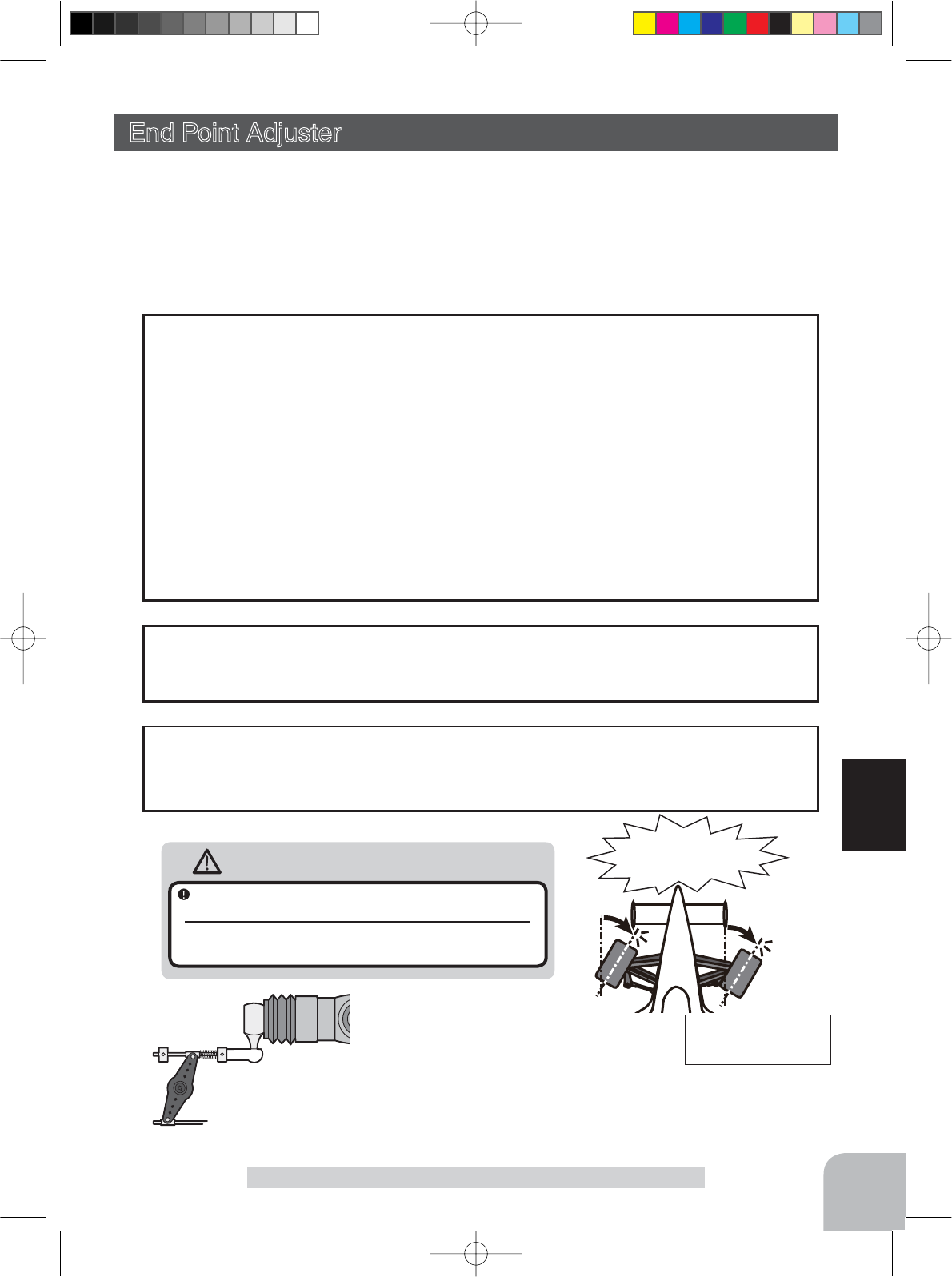
49
Function
End Point
End Point Adjuster (All channel)
Use this when performing left and right end point adjustments, throttle high side/brake
side operation amount adjustment, channel 3 and channel 4 servo up side/down side op-
eration amount adjustment during linkage.
- Correct the maximum steering angle for left and right steering angles when there is a
difference in the turning radius due to the characteristics, etc. of the vehicle.
The End point function basically determines the maximum steering angle of each chan-
nel.
The functions shown below may have been adjusted or the operating range set by End
point function may be exceeded. Check the linkage each time the following functions
are adjusted.
- Sub trim (all channels)
- Program mixing slave side (all channels)
- Tilt mixing (steering, channel 3)
- Idle up (throttle)
- Start Function, Engine Cut (throttle)
- Throttle acceration (throttle)
Maximum steering angle
Brake rate trim allows adjustment of the brake side operation amount during operation.
Therefore, when the operating angle is adjusted with throttle End point, Brake rate trim
must also be taken into account.
Brake rate trim
:KHQWKHVWHHULQJDQJOHLVLQVXI¿FLHQWHYHQWKRXJK(QGSRLQWLVLQFUHDVHGWRPD[LPXP
(140%), the steering angle can be increased somewhat by using program mixing.
(Setup example: See page 96.)
Remark
Warning
Operate each servo over its full stroke and be sure
the linkage does not bind or is not loose.
The continuous application of unreasonable force to a servo may
cause damage and excessive battery drain.
Adjust the throttle servo so that unreasonable force is not applied when the engine carburetor is fully
open, fully closed, and the brakes are applied fully.
If the brakes overheat while running, their ability to function properly decreases. Before running, adjust
the suitable maximum servo travel so that unreasonable force is not applied even when the servo travel
is increased while running.
Adjust the steering servo so that unreason-
able force is not applied to the servo by the
chassis at maximum servo travel.
Decide the End point
value at the contact
point.
Caution!
A whining noise indicates that the
steering servo is improperly set.
4PX-Eng-08-Function-46-65.indd 49 2014/07/18 17:14:49
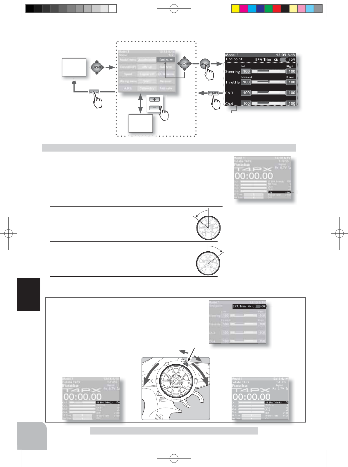
100
DT1
or
MENU 1 screen
HOME
screen
MENU 2
screen
LR
EPA Trim
ON/OFF
Pres
s
Pres
s
Pres
s
Pres
s
50
Function
End Point
(Preparation)
- Before setup of the steering end point adjustment, set the steer-
ing D/R dial (initial setup: DT5) to the maximum steering angle
position 100%.
- Select the setting item "Steering Left" by (JOG) button operation
and make the following adjustments:
1Steering (left side) adjustment
Turn the steering wheel fully to the left and use the
(+) or (-) buttons to adjust the steering angle.
Steering end point adjustment
Quick EPA
When EPA trim is turned on, the steering angle (end point) can be
adjusted by steering trim set digital trim or dial. (Steering trim initial
setting: DT1)
Steering right side adjustment
With the steering wheel turned fully to the
right, steering is adjusted by steering trim.
Temporarily displayed at this part of the
HOME screen as shown in the figure below.
Steering left side adjustment
With the steering wheel turned fully to the
left, steering is adjusted by steering trim.
Temporarily displayed at this part of the
HOME screen as shown in the figure below.
2Steering (right side) adjustment
Turn the steering wheel fully to the right and use
the (+) or (-) buttons to adjust the steering angle.
3When ending setting, return to the menu screen by pressing
the (END) button.
Setting item (channel and direction)
Steering (left side/right side)
Throttle (foward side/brake side)
3rd channel (up side/down side)
4th channel (up side/(down side)
Adjustment buttons
Adjust with the (+) and (-) but-
tons.
- Return to the initial value "100"
by pressing the (+) and (-) but-
tons simultaneously for about 1
second.
Note
Step #1 & #2 are done when
the receiver is in the on position
installed on the chassis. You're
watching the wheels reach their
maximum end point.
Steering End point :0~140
Initial value :100
4PX-Eng-08-Function-46-65.indd 50 2014/07/18 17:14:50
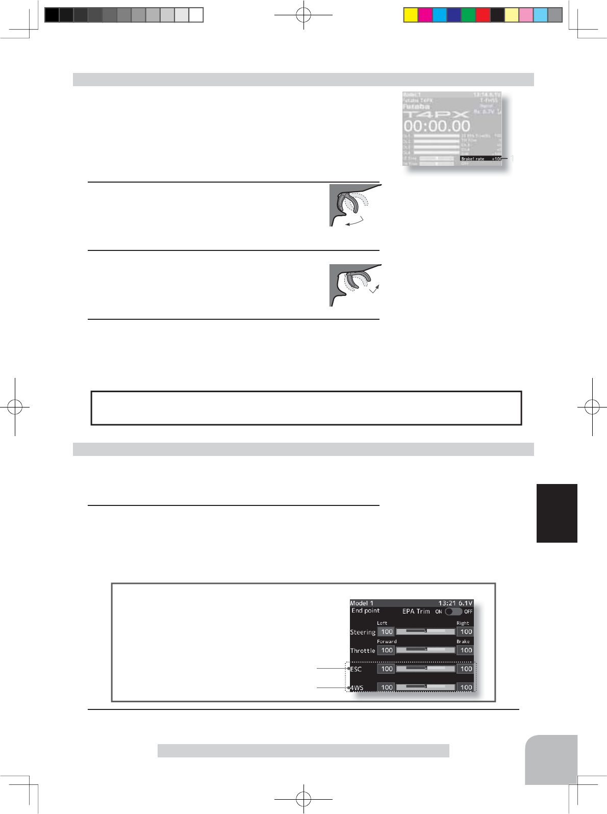
100
51
Function
End Point
When Trigger Ratio (p.66) was set to 100:0, brake operation is stopped and the throttle
(brake side) cannot be adjusted.
Dual ESC mixing :Front ESC
4WS mixing: Rear servo
Spare channel display
When a mixing function is set at a spare channel, the dis-
play changes.
This is an example of setting dual ESC mixing at the 3rd
channel and 4WS mixing at the 4th channel.
(Preparation)
- Before setting the throttle end point adjustment, set the throttle
ATL dial (initial setup: DT6) to the maximum throttle angle po-
sition 100%.
- Select the setting item "Throttle Forward" by (JOG) button op-
eration and make the following adjustments:
1Throttle (forward side) adjustment
Pull the throttle trigger fully to the high side and use
the (+) or (-) buttons to adjust the throttle angle.
However, when using an FET amp, set to 100%.
2Throttle (brake side/reverse side) adjustment
Move the throttle trigger fully to the brake side
and use the (+) or (-) buttons to adjust the throttle
angle. However, when using an ESC, set to 100%.
3When adjusting the throttle angle of another channel imme-
diately after this, see the adjustment method for that channel.
When ending setting, return to the menu screen by pressing
the (END) button.
Throttle end point adjustment
(Preparation)
- Select the channel whose steering angle is to be adjusted and
the direction by (JOG) button operation.
1Use the (+) or (-) buttons to adjust the servo angle.
3rd & 4th channel servo end point adjustment
Adjustment buttons
- Use the (+) and (-) buttons to
make adjustments.
- Return to the initial value "100"
by pressing the (+) and (-) but-
tons simultaneously for about 1
second.
- Please see previous note on
page 50.
3rd & 4th channel End point
:0~140
Initial value :100
Adjustment buttons
- Use the (+) and (-) buttons to
make adjustments.
- Return to the initial value "100"
by pressing the (+) and (-) but-
tons simultaneously for about 1
second.
- Please see previous note on
page 50.
Throttle End point :0~140
Initial value :100
2When ending setting, return to the menu screen by pressing the (END) button.
4PX-Eng-08-Function-46-65.indd 51 2014/07/18 17:14:51