Contents
- 1. User Manual-Part 1 (Page 1-51)
- 2. User Manual-Part 2 (Page 52-111)
- 3. User Manual-Part 3 (Page 112-163)
User Manual-Part 3 (Page 112-163)
HOME
screen
or
MENU 1 screen
MENU 2
screen
Pres
s
112
Function
Model Select
Current model # is blue
Model #.
M1~M40
Model selection button
- Select the model by (JOG) button
up or downt operation.
Select the model by (JOG) button operation
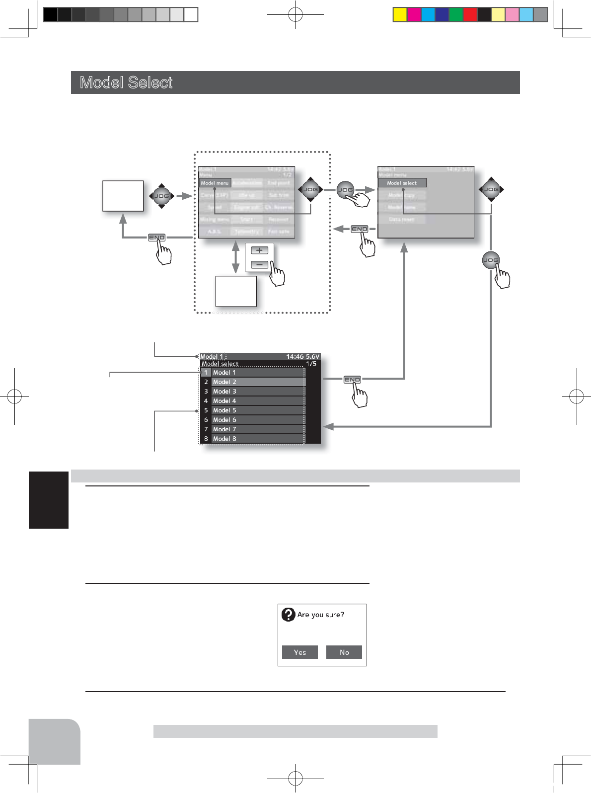
Model Select
Forty model data (model data for 40 R/C cars) can be saved in the T4PX transmitter and
used when the relevant model data is called.
Current model name
1 (Model No. selection)
Select the model by (JOG) button up or down operation.
When the (JOG) button up operation is performed from the
cursor position on the top row or the (JOG) button down op-
eration is performed from the cursor position on the bottom
row, the page changes.
2 (Model selection execution)
When the model was selected, press
the (JOG) button. The confirmation
message "Are you sure?" appears.
To execute selection, select "Yes" and
press the (JOG) button and to cancel
Using the model selection function
Model selection set button
- The (JOG) button are pressed.
selection, select "No" and press the (JOG) button.
3When ending setting, return to the menu screen by pressing the (END) button.
Pres
s
Pres
s
Pres
s
Pres
s
Pres
s
4PX-Eng-08-Function-104-156.indd 112 2014/07/18 17:36:10
or
MENU 1 screen
HOME
screen
MENU 2
screen
113
Function
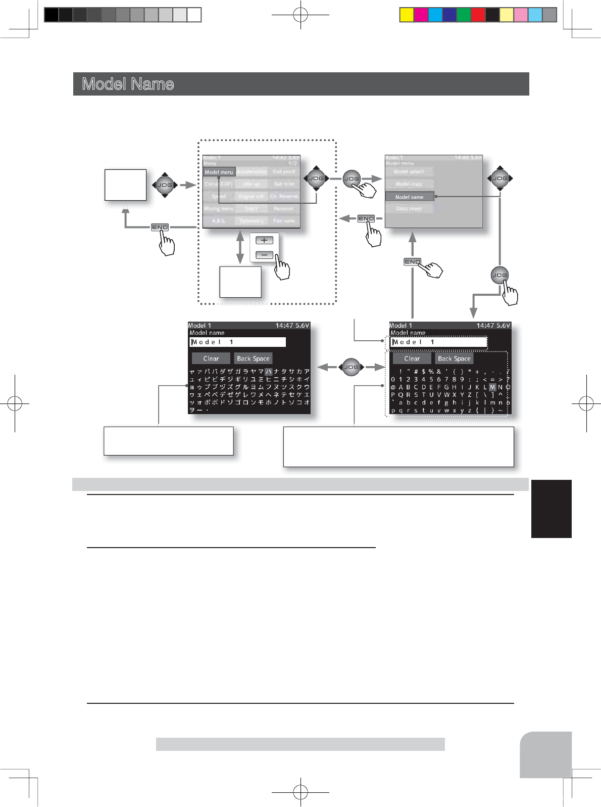
Model Name
Model name
1 (Moving the cursor to the character you want to change.)
Move the cursor to the model name character you want to set or change by pressing the (+)
or (-) button. The selected character blinks.
Setting the model name and user name
Character select/set button
- Select the character by (JOG)
button up, down, left, or right
operation and enter the char-
acter by pressing the (JOG)
button.
Model Name
This function allows you to assign a ten character name to each model memory.
Select the character with the (JOG) button.
Clear:All characters of the model name are deleted.
Back Space:The character at the left of the cursor is deleted.
"Katakana" of the Japanese
character is displayed on page 2.
2 (Selecting the character to be used)
Move the cursor by (JOG) button up, down, left, or right op-
eration, and select the characters to be used from the char-
acter list at the bottom of the screen. After deciding the char-
acters to be used, press the (JOG) button. The characters
are selected and the model name character string moves to
the right. When "Back space" on the center row is selected
and the (JOG) button is pressed, the character at the left of
the vertical cursor is deleted. When "Clear" is selected and
the (JOG) button is pressed, all the characters are deleted.
Pres
s
Pres
s
Pres
s
Pres
s
3When ending setting, return to the menu screen by pressing the (END) button.
Pre
Pres
s
Pre
Pres
s
4PX-Eng-08-Function-104-156.indd 113 2014/07/18 17:36:10
HOME
screen
or
MENU 1 screen
MENU 2
screen
T4PX transmitter or microSD
card selection
114
Function
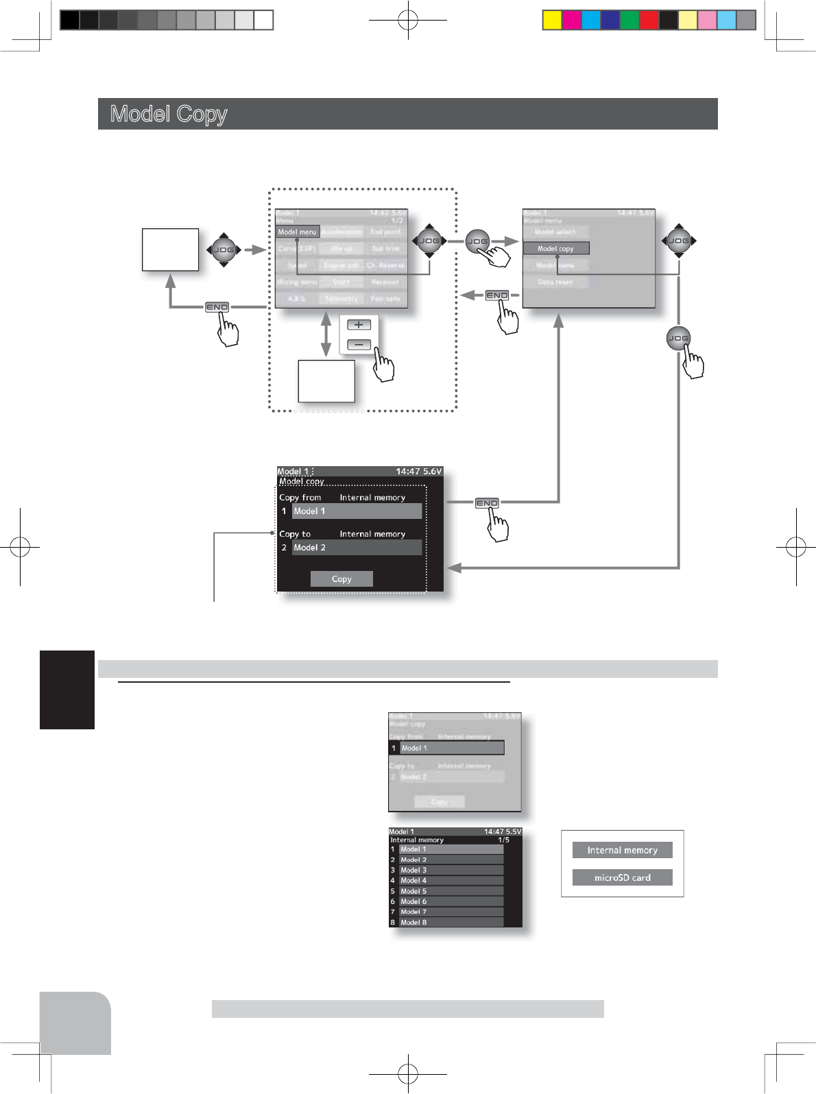
Selects the copy source model and copy destination model data.
Model Copy
Model Copy
The contents of the model memory can be copied to another model memory. The contents
can also be saved or stored in a microSD card for copying to another T4PX.
Model copying
Setup item selection
- Select by (JOG) button up or
down operation.
Model number selection
- The (JOG) button are pressed
Pres
s
Pres
s
Pres
s
Pres
s
Pres
s
1 (Copy source model selection)
Select the setting item "Copy source"
by (JOG) button up or down operation.
Press the (JOG) button. A list of the
models stored in the T4PX transmit-
ter is displayed. Select the model by
(JOG) button up or down operation,
and press the (JOG) button.
When a microSD card is installed in
the T4PX, a screen for selecting T4PX
model memory (Internal memory) or
microSD card is displayed.
After selecting either T4PX model
memory or microSD card by (JOG)
button, select the model.
Pre
Pres
s
4PX-Eng-08-Function-104-156.indd 114 2014/07/18 17:36:11
T4PX transmitter or microSD
card selection
115
Function
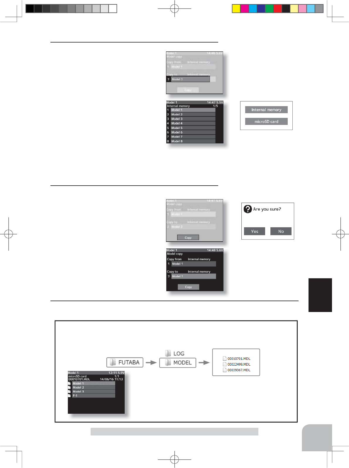
microSD card storage destination
When a microSD card is installed in the T4PX, a folder called "Futaba" is created, and folders
called "LOG" and "MODEL" are created in it. The "MODEL" folder contains the model data.
When the T4PX model data is copied, and the copy source data
is selected from the model data stored in the microSD, a model
list like that shown at the left is displayed.
Model data
Model Copy
4When ending setting, return to the menu screen by pressing the (END) button.
Setup item selection
- Select by (JOG) button up or
down operation.
Model number selection
- The (JOG) button are pressed
2 (Copy destination model selection)
Select the setting item "Copy Source"
by (JOG) button up or down opera-
tion, and press the (JOG) button. A
list of the model numbers saved in the
T4PX transmitter is displayed. Select
the model by (JOG) button up or down
operation, and press the (JOG) button.
When a microSD card is installed in
the T4PX transmitter, a screen for se-
lecting the models in the T4PX trans-
mitter (Internal memory) or the models
in the microSD card is displayed.
After selecting the screen by (JOG) button, select the model.
-The model currently in use cannot be selected.
-Since the copy destination cannot be overwritten when it is in a microSD card, a models list is not displayed and
the model is saved directly to the microSD card.
3 (Copy execution)
After checking that the copy source
and copy destination models are cor-
rect, select the setting item "Copy ex-
ecution" by (JOG) button up or down
operation, and press the (JOG) button.
The confirmation message "Are you
sure" appears. To execute copy, select
"Yes" and to cancel copy, select "No"
by (JOG) button.
When the copy destination model
name becomes the same name as the
copy source, copying is complete.
4PX-Eng-08-Function-104-156.indd 115 2014/07/18 17:36:11
HOME
screen
or
MENU 1 screen
MENU 2
screen
116
Function
Data Reset
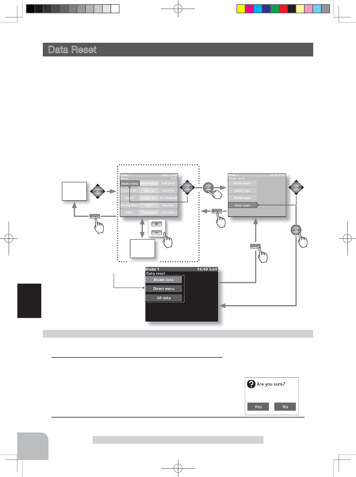
Data Reset
Select the reset type by (JOG) button up or down operation
and press the (JOG) button.
1(Reset execution)
Press the (JOG) button. The "Are you sure?" confirmation
message appears. To execute, select "Yes" and to cancel se-
lect "No" and press the (JOG) button.
This completes resetting.
Data Reset
This function resets the contents of the currently called model memory.
The reset method can be selected from among the 3 types described below. These resets
do not initialize the adjuster function, system function, user name, and receiver type, servo
type selection function.
Model data
Initializes only the function setting data. The direct menu function is not initialized.
Direct menu
Initializes the direct menu function. Other settings are not initialized.
All data
Initializes the menu function, direct selection function, and the setting data of each function.
Setup item selection
- Select by (JOG) button up or
down operation.
Reset execution button
- (JOG) buttons pressed.
Reset type selection
2
When ending setting, return to the menu screen by pressing the (END) button.
Pres
s
Pres
s
Pres
s
Pres
s
Pres
s
Pre
Pres
s
4PX-Eng-08-Function-104-156.indd 116 2014/07/18 17:36:12
117
Function
HOME
screen
MC Link Function (ESC Link)
or
MENU 2 screen
MENU 1
screen
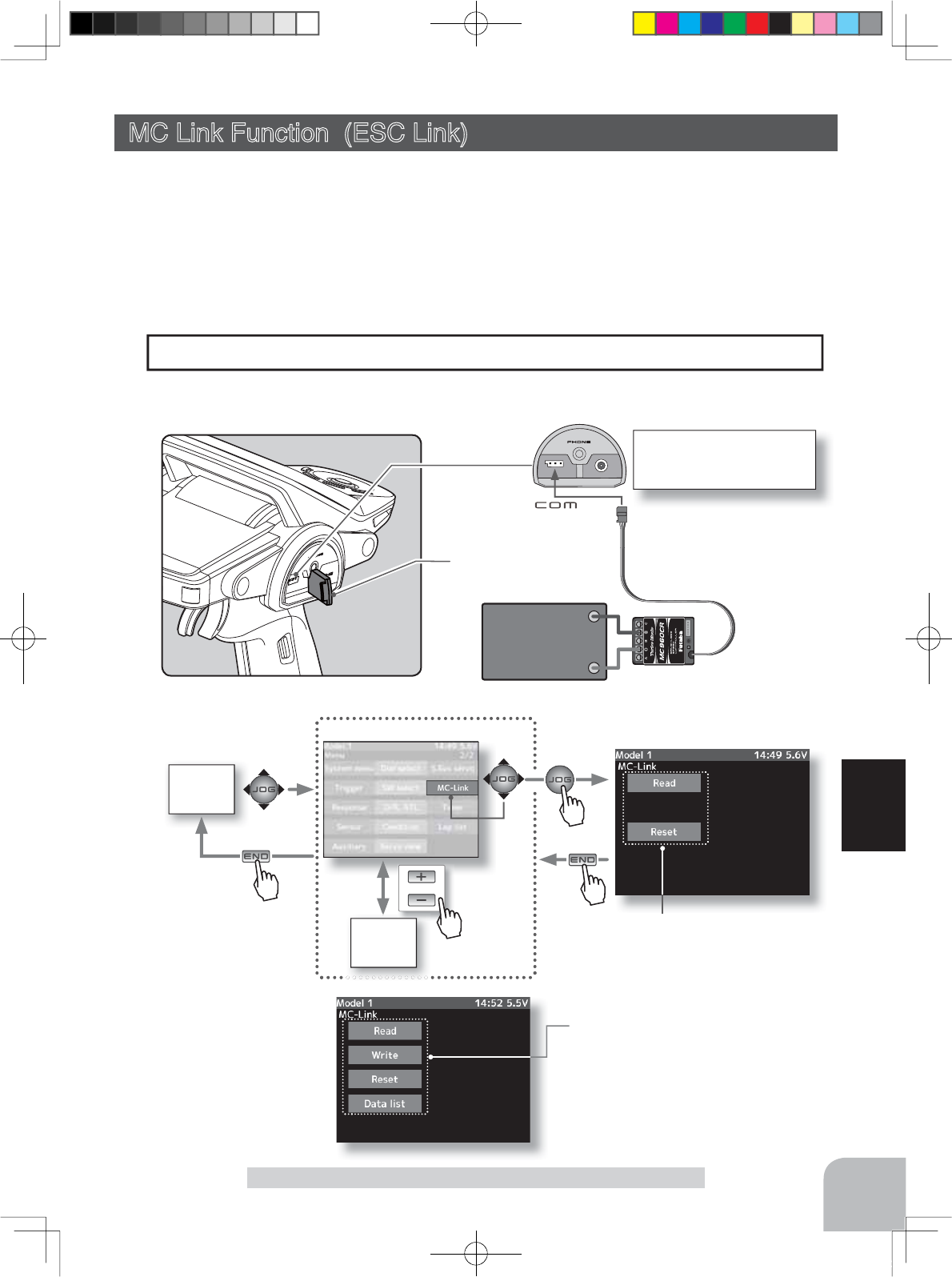
Communication port
Cover
Battery
Connecting ESC receiver
connector to the transmitter
Communication port.
Setup item (before it reads)
Read
Reset
Setup item (after it reads)
Read
Write
Reset
Data list
-Also connect the battery at the ESC side.
MC Link Function (ESC Link)
This is a special function which allows Futaba motor controller (MC) data changes to be set
by the T4X transmitter (MC960CR, MC950CR, MC851C, MC602C, MC402CR, etc.).
However, some data changes require a PC and Link software.
This function is used by connecting ESC directly to the transmitter.
8VHWKHYDULRXVRSWLRQDOVHUYRH[WHQVLRQFRUGVDFFRUGLQJWRWKHGLVWDQFHEHWZHHQWKHWUDQVPLWWHU
and ESC.
Pres
s
Pres
s
Pres
s
Pres
s
4PX-Eng-08-Function-104-156.indd 117 2014/07/18 17:36:12
118
Function
MC Link Function (ESC Link)
(Preparation)
-Connect the T4PX and ESC in accordance with the connection diagram shown on page 117.
-Connect the battery to ESC.
1Turn power on the transmitter. "MC link" menu is displayed refer-
ring to the map of page117. Set the FET amp power switch to
the ON position.
Using the ESC Link function
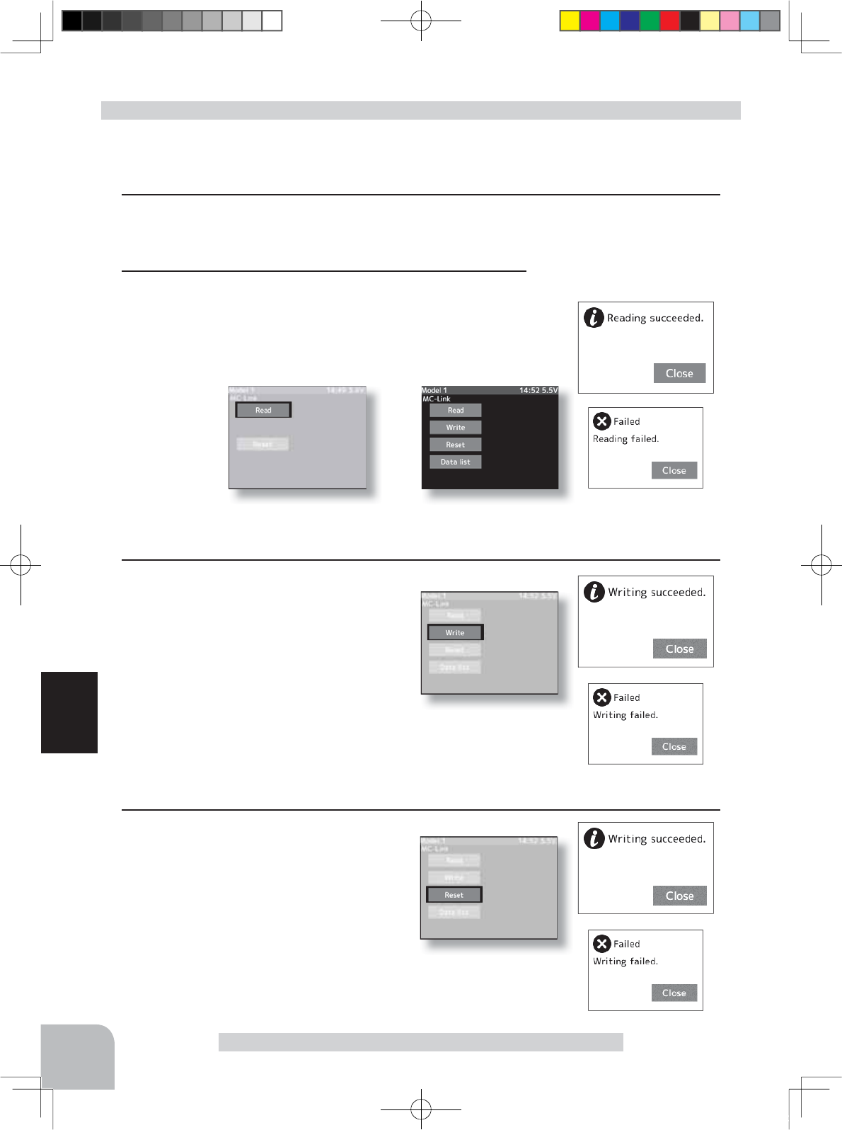
2 (ESC read)
Execute this function to read the connected ESC type and
the data currently set at the ESC.
-Select the setting item "Read" by (JOG) button up or down
operation, and press the (JOG) button.
-"Reading succeeded"
is displayed on the screen
and the ESC type and currently set contents are read.
- If "Faild"
is displayed on the screen
, communication with the ESC is not being performed normally. Check the
T4PX and ESC connection and the battery connection to ESC and the ESC power switch and repeat "Read".
3 (Writing to ESC)
Execute this function to write the setting
data to ESC. See pages 120~125 for the
setting data contents.
-Select the setting item "Write" by (JOG)
button up or down operation, and press
the (JOG) button.
-"
Wrieing succeeded
" is displayed on the screen and the setting data is written to
ESC.
- If "Faild"
is displayed
on the screen, communication with the ESC is not being per-
formed normally. Check the T4PX and ESC connection and the battery connection to
ESC and the ESC power switch and repeat "Write".
- Different type ESC data cannot be written. If writing is attempted, "Faild" is displayed
on the screen
.
4 (Initialization)
Write the factory set ESC setting data to
the connected ESC and T4PX.
-Select the setting item "Reset" by (JOG)
button up or down operation, and press
the (JOG) button.
-"
Wrieing succeeded
" is displayed on the screen
and the setting data is written to ESC.
-
If "Faild"
is displayed
on the screen, communication with the ESC is not being
performed normally. Check the T4PX and ESC connection and the battery con-
nection to ESC and the ESC power switch and repeat "Write".
Setup item selection
- Select by (JOG) button up or
down operation.
Reset execution button
- (JOG) buttons pressed.
4PX-Eng-08-Function-104-156.indd 118 2014/07/18 17:40:12
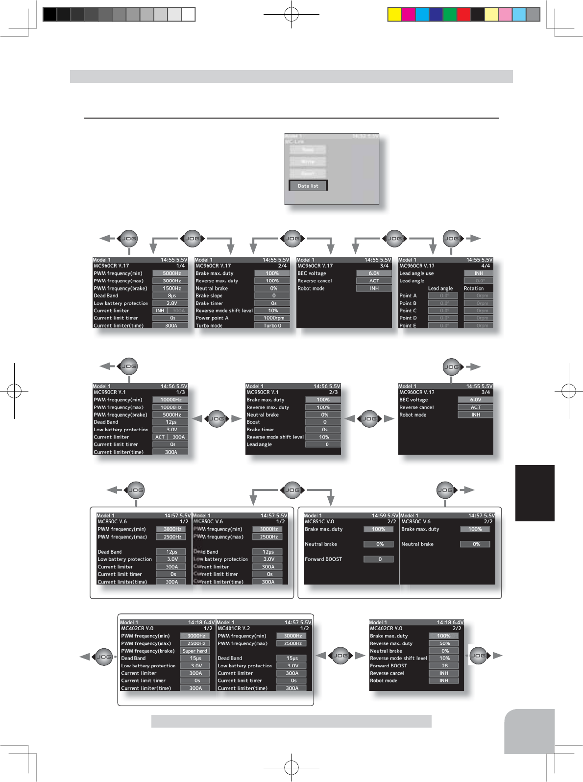
MC950CR page1
MC602C/851C
page
1MC601C/850C
page
1
MC402CR
page
1 MC401CR
page
1
MC950CR page2
MC601/602C/851C
page
2
MC850C page2
MC401/402CR
page
2
MC950CR page3
MC940/960CR
page1
To page4 To page1
To page1
To page1
To page1
To page3
To page2
To page2
MC940/960CR
page2
MC940/960CR
page3 MC940/960CR page4
119
Function
MC Link Function (ESC Link)
(Preparation)
(6&LVUHDGUHIHUULQJWRWKHH[SODQDWLRQRISDJH
1Select the setting item "Data list" by
(JOG) button up or down operation, and
press the (JOG) button.
Data list
Setup item selection
- Select by (JOG) button up or
down operation.
Reset execution button
- (JOG) buttons pressed.
4PX-Eng-08-Function-104-156.indd 119 2014/07/18 17:36:13
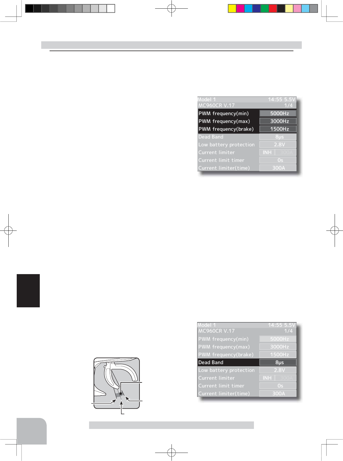
"min" which sets the frequency when the load is small, is set to the high frequency side (large
value) when extension is desired after straightaways and curves.
"max" which sets the frequency when the load is large, is set to the high frequency side (large
value) when you want to suppress the rise from low speed and when motor heating and
commutator roughness are sensed.
When the rise from low speed is poor, and becomes bad even when "max" is set to the low
frequency side, use the log data to check if there was a momentary voltage drop. When you
want to suppress the overall power, lengthen the run time, and otherwise improve efficiency,
set both "max" and "min" to the high frequency side. When you want to set a fixed PWM
frequency at full range regardless of the load current, set PWM frequency (at Max. load) and
PWM frequency (at Min. load) to the same value.
Throttle neutral position
Dead Band
Point at which brakes start
taking effect
Position at which motor
starts to run
120
Function
MC Link Function (ESC Link)
PWM frequency (min)
MC401,402CR/601,602C/850,851C :0.1kHz(100Hz) 10kHz (10000Hz)
MC950CR :0.5kHz(500Hz) 30kHz(30000Hz)
MC940,960CR :1kHz(1000Hz) 30kHz(30000Hz)
Same as Link software PWM frequency (at Min. load),
MIn sets the "0"A PWM frequency at minimum load.
PWM frequency (max)
MC401,402CR/601,602C/850,851C:0.1kHz(100Hz) 10kHz (10000Hz)
MC950CR :0.5kHz(500Hz) 30kHz(30000Hz)
MC940,960CR :1kHz(1000Hz) 30kHz(30000Hz)
Same as Link software PWM frequency (at Max. load).
MAX sets the PWM frequency at maximum load at the out-
put current limit value set by Current Limiter.
PWM frequency (brake)
MC402CR/602C/851C (MC401,601,850 cannot be adjusted 2kHz fixation)
:Normal(2000Hz) /Hard(1000Hz) /Super hard(500Hz)
MC950CR :0.5kHz(500Hz)30kHz(30000Hz)
MC940,960CR :1kHz(1000Hz)30kHz(30000Hz)
Same as Link software Brake PWM at frequency.
This setting can set the brake PWM frequency.
Dead Band
All type :±2μs~±50μs
Same as Link software Dead Band.
This sets the range (neutral point range) over which the ESC does
not respond to transmitter throttle operation.
The larger the set value, the wider this range.
System function setup
1Select the setting item by (JOG) button up, down, left, or right operation.
Set the value by (+) and (-) button.
4PX-Eng-08-Function-104-156.indd 120 2014/07/18 17:36:13
121
Function
MC Link Function (ESC Link)
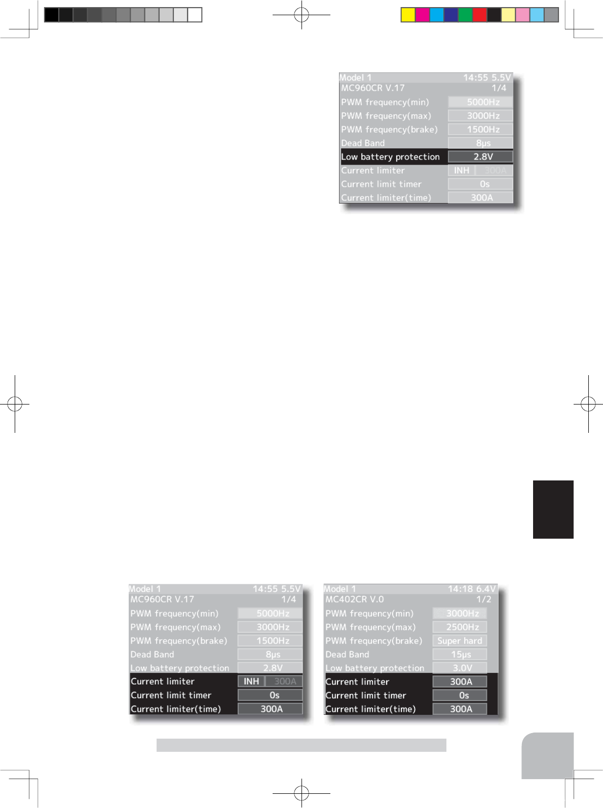
Low Bat Protection
MC401,402CR/601,602C/850,851C:2.5V 6.0V
MC950CR/MC940,960CR 2.5V 7.5V
Same as Link software Low Bat Protection.
When the power supply voltage drops, the output current to the
motor is limited and supply voltage to the receiver is ensured.
When the power supply voltage drops to the set voltage, a pro-
tection circuit operation alarm is activated and output to the motor
is cut. The protection circuit is automatically reset by recovery of
the power supply voltage.
Current Limiter
MC401,402CR/601,602C/850:50A 300A, INH
MC851C :50A~300A(can not INH)
MC950CR/MC940,960CR:50A~500A, INH
Same as Link software PWM frequency (at Max. load).
MAX sets the PWM frequency at maximum load at the out-
put current limit value set by Current Limiter.
Current limiter INH/ACT setting
With the MC950CR and MC940/960CR move the cursor to current limiter "INH(Off)/ACT(On)" and select INH or
ACT with the (+) or (-) button.
With other MC, when the (+) button is pressed from the current limiter maximum value, INH(Off) is set.
The MC851C does not have an INH(Off) setting.
Current Limit timer
MC401,402CR/601,602C/850,851C:0sec(OFF)240sec
MC940,960CR:0sec(OFF)~240sec (MC950CR can not)
Same as Link software Current Limit timer.
The output current can be limited up to the set time lapse from the start of running. This is effective in preventing
the motor from outputting wasted energy when the voltage is high immediately after the power battery was re-
charged.
"Current Limiter (time)" sets the time the output current is limited. This function is disabled when set to "0" sec.
Since the Current Limit Timer starts when the throttle is operated to the forward side and current is output to the mo-
tor, this function begins to operate when the motor is run during trim adjustment, etc.
Current Limiter (time)
MC401,402CR/601,602C/850,851C :50A~300A
MC940,960CR :50A~500A (MC950CR can not)
"Current Limit timer " (Time Limit) sets the maximum output current within the time the output current is limited.
4PX-Eng-08-Function-104-156.indd 121 2014/07/18 17:36:14
MC401,402CR/MC950CR/MC940,960CR
MC401,402CR MC601,602,851C
MC401,402CR MC950CR/MC940,960CR
MC601,602C/MC850,851C
100
50
0
%
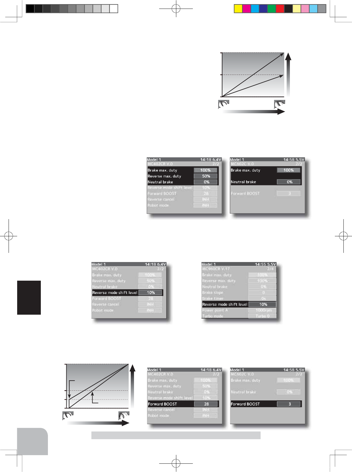
Brake (Reverse) operation
Braking force
Reverse Power
122
Function
MC Link Function (ESC Link)
Brake max. duty
All type :0%~100%
Same as Link software Brake Max. Duty.
This setting can set the braking force between the neutral point and
Max brake point.
The larger this value, the greater the braking force. When set to
"0%", the brakes are not effective.
Reverse max. duty
MC401,402CR/MC950CR/MC940,960CR :0%~100%
Same as Link software Reverse Max. Duty.
This setting can set the reverse power between the neutral point and Max reverse point.
The larger this value, the greater the reverse power. When set to "0%", the reverses are not
effective.
Neutral brake
All type :0%~100%
Same as Link software Current Limit
timer.
Make this setting when you want to use
the brakes at the neutral throttle (OFF)
position by throttle operation. The larger
this value, the greater the braking force.
When you want to use the neutral
brake, set this value to "0%".
100
50
0
Forward operation
Throttle response
FWB "50"
FWB "0"
Reverse mode shift level
MC401,402CR/MC950CR/MC940,960CR :0%~100%
Same as Link software Reverse Mode Shift Leve.
The reverse operation can be done with the throttle trigger to be thrown from brake status to the neutral. The value
can set the amount of the brake in order to switch to the reverse operation.
Forward BOOST
MC401,402CR/MC601,602C/MC851C :0%~100%
Same as Link software Forward Boost (Boost).
Operation near the throttle trigger neutral position becomes a sharp rise.
4PX-Eng-08-Function-104-156.indd 122 2014/07/18 17:36:14
MC940,960CRMC401,402CR MC950CR
MC940,960CR
MC940,960CR/MC950CR
123
Function
MC Link Function (ESC Link)
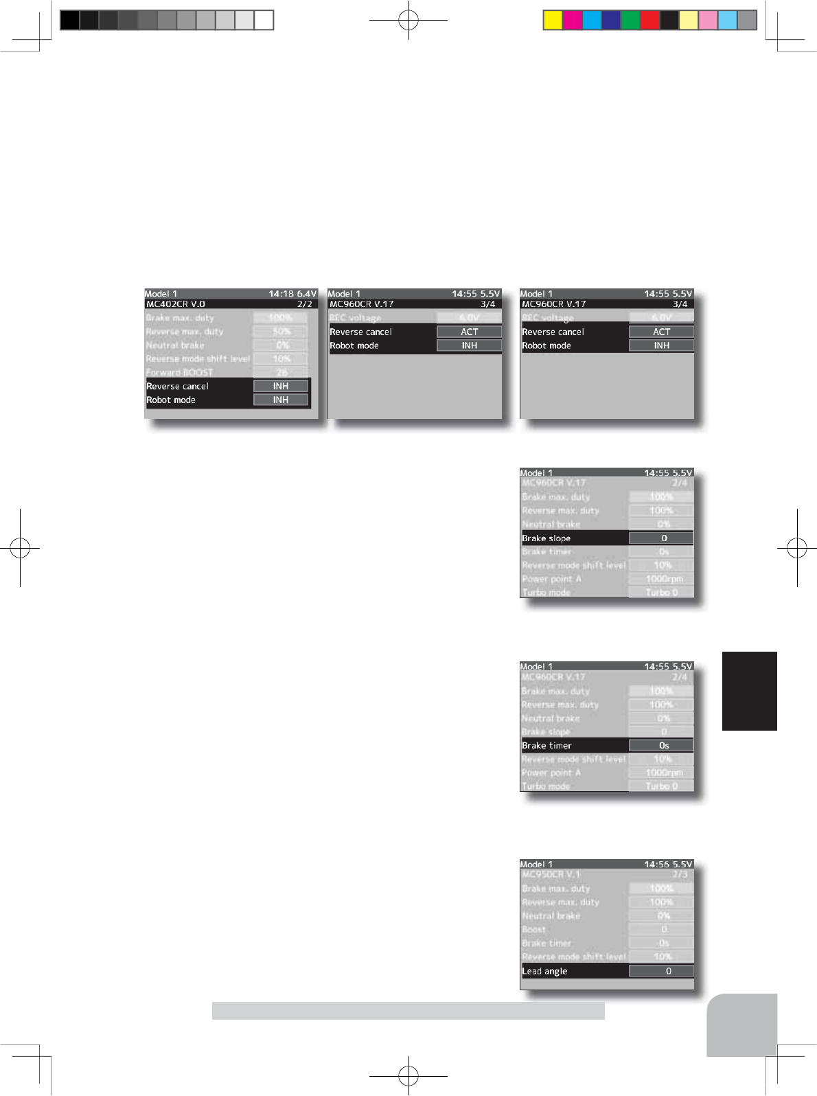
Reverse cancel
MC401,402CR/MC950CR/MC940,960CR :ACT/INH
Same as Link software Reverse Cancel.
When set to "ACT", reverse operation is not performed.
Robot mode
MC401,402CR/MC950CR/MC940,960CR :ACT/INH
Same as Link software Robot Model.
When set to "ACT", breke operation is not performed, there is only forward and reverse operation.
Brake slope
MC940,960CR/ :0~300
Same as Link software Brake Slope.
This function adjusts the braking effect when the throttle was returned (throttle
off). It cancels operation like that called engine brake of actual vehicles.
Brake timer
MC940,960CR/MC950CR :0sec~300sec
Same as Link software Brake Timer.
When the reverse function is used, ordinarily if the trigger is not moved to the
brake (reverse) side and then returned from the brake operation position to the
neutral position, reverse operation will not be performed. However, when used
by intentionally moving the neutral point to the forward side, if brake operation
is repeated, reverse operation may be performed even if the trigger is not re-
turned to the neutral position. The time required to switch to reverse operation
can be set to prevent this from occurring.
Lead angle
MC950CR/ :0~1500
Same as Link software Lead Angle.
The lead angle of the motor can be set at the MC950CR side. However, we
recommend that it normally be set to "0". Since this setting is premised on
setting by referring to the speed log by the Link software.
4PX-Eng-08-Function-104-156.indd 123 2014/07/18 17:36:14
MC940,960CR
124
Function
MC Link Function (ESC Link)
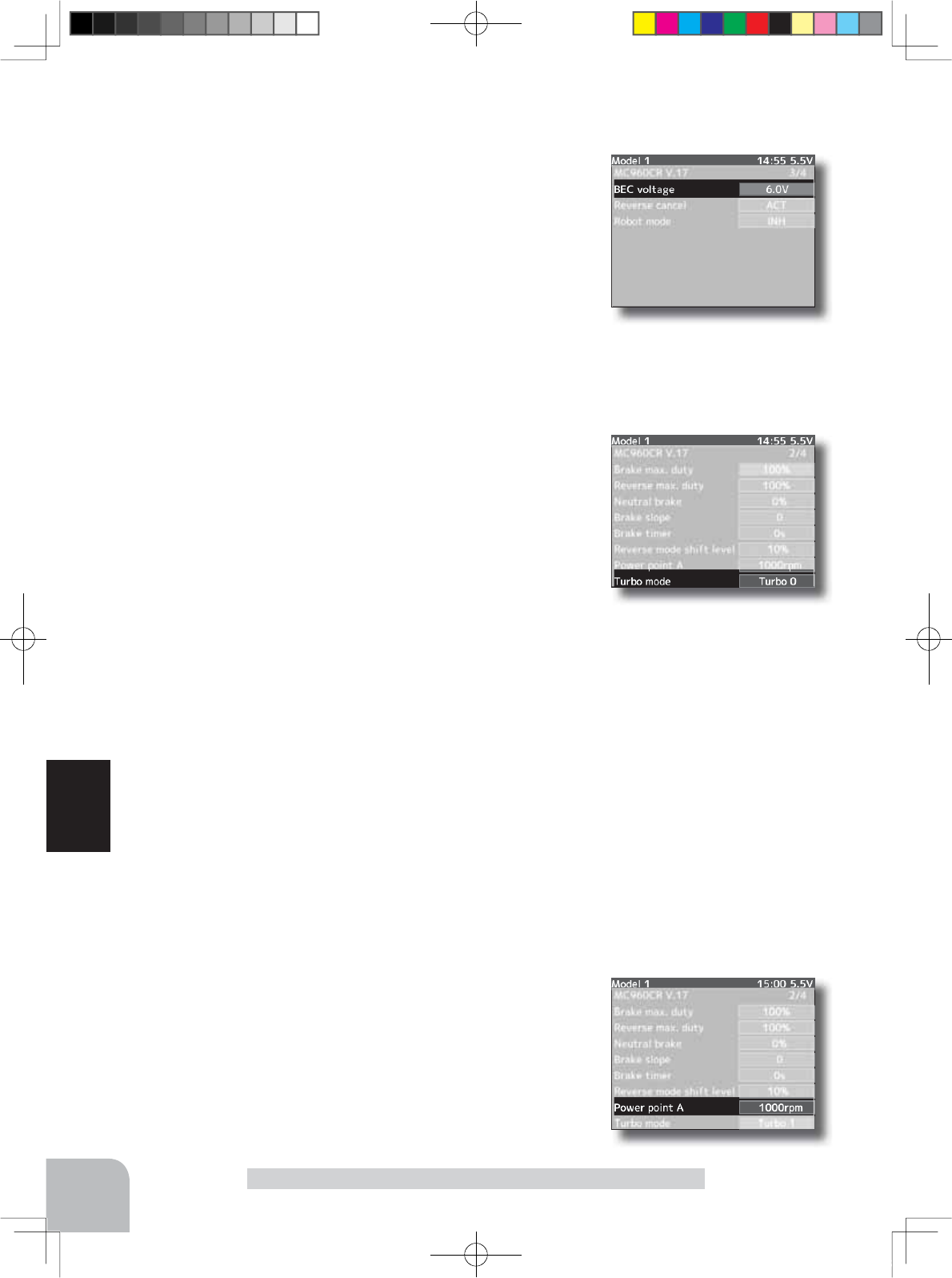
BEC voltage
MC940,960CR/ :6.0V/7.4V
Same as Link software BEC Volt.
The receiver BEC voltage can be selected from 6.0V and 7.4V. Match the volt-
age to the rating of the servo connected to the same receiver. This BEC voltage
cannot output a voltage higher than the input voltage.
For instance, if a 6.0V receiver and servo are used with a power supply voltage
of 7.4V or more, set the BEC voltage to 6.0V and when a high voltage receiver
and servo are used, set the BEC voltage to 7.4V.
Turbo mode
MC940,960CR/ :Turbo0/Turbo1/Turbo2
Same as Link software Turbo Mode.
This function sets the turbo mode. More power can be displayed by using the turbo mode. Depending on the set-
ting, the motor and ESC may be damaged so make this setting carefully.
(Note) When "Lead angle use" is INH, lead angle setting will not operate
even if set to "Turbo1" or "Turbo2." (Turbo mode disabled, Turbo0=Off)
-Turbo0 mode: (No Lead Angle mode) Lead angle - No
When used in races in which the lead angle setting function is inhibited by
ESC, set to this mode. The lead angle function is disabled the same as if
"Lead angle use" was turned off.
When the lead angle function was disabled by the method described above,
the MC940,960CR shows that the lead angle function is off by blinking a
blue LED at an ON 0.1 second, OFF 0.9 second cycle at the neutral point.
-Turbo1 turbo mode: (Lead Angle mode) Lead angle – Yes
The output can be increased by setting a lead angle.
Depending on the set value, the motor may be damaged so increase the lead angle value in steps from a small
value while observing the conditions.
Turn on "Lead angle use" and adjust the lead angle by "Lead angle" and point A, B, C, D, E (A, B, C, D, E Lead
angle) value.
-Turbo2 power mode: (Power Mode) Lead angle – Yes
Displays still more power than a turbo.
However, since even a motor applies a large load on the ESC, make the lead angle larger in steps from a small
value while observing the conditions.
Turn on "Lead angle use" and adjust the lead angle by "Lead angle" and point A, B, C, D, E (A, B, C, D, E Lead
angle) value.
Power point A
MC940,960CR/ :0rpm~100000rpm
Same as Link software Power Point A.
When the turbo mode is power 2 (Power mode) and the lead angle is large,
movement may become stiff when entering the course, etc. In this case, make
operation smooth by lowering the set speed at power point A.
This function is not performed in modes other than Turbo 2.
4PX-Eng-08-Function-104-156.indd 124 2014/07/18 17:36:15
When using in races in which the lead angle setting function is inhibited by the ESC, set "Lead
angle use" to "INH". The "Lead angle use" setting has priority over "Turbo mode". If "Lead angle
use" is set to "INH", the lead angle setting function can be turned off even if "Turbo mode" is set to
"Turbo1" or "Turbo2".
The MC940,960CR shows that the lead angle setting function is OFF ("0" timing) by blinking a LED.
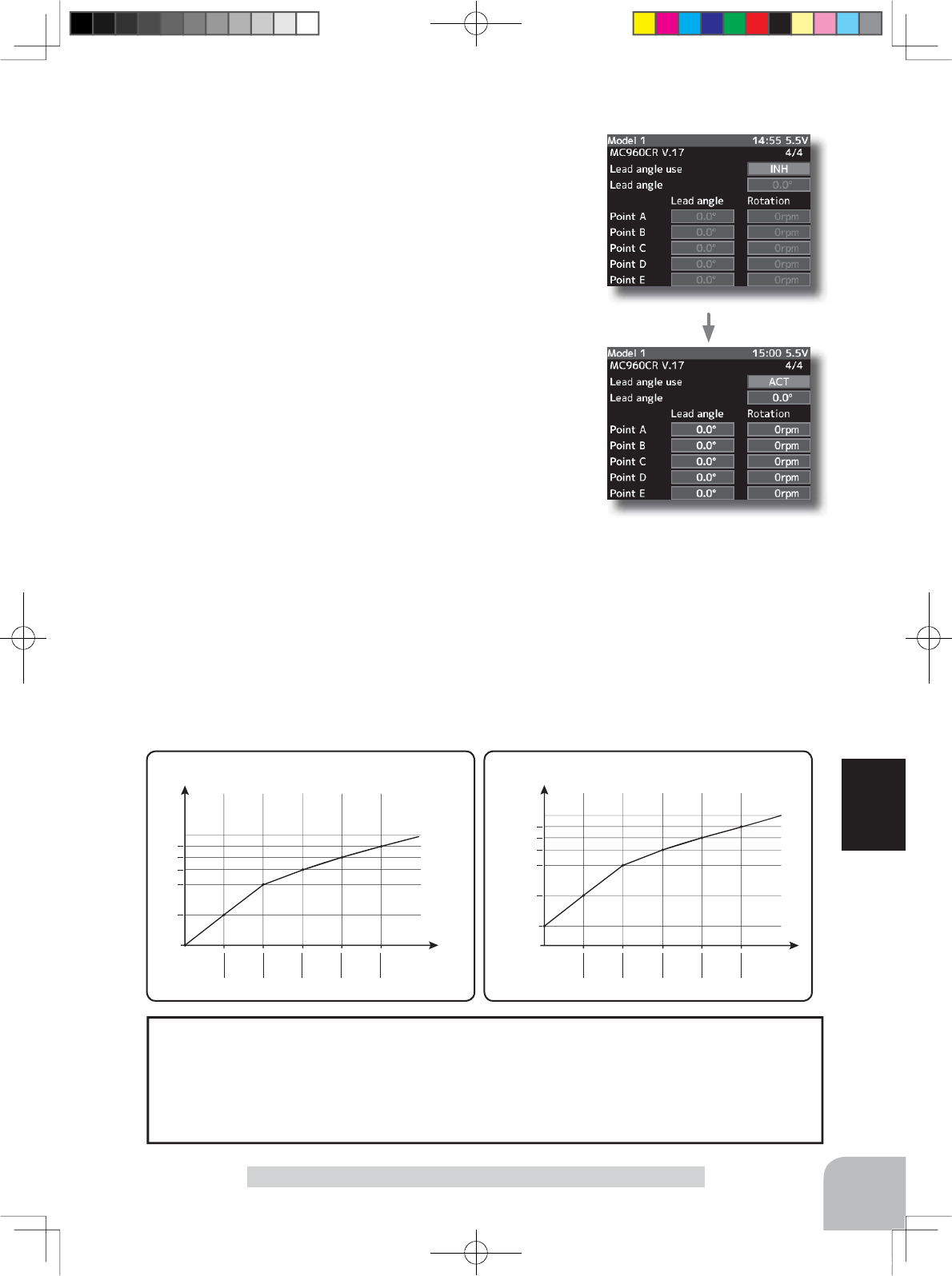
The "Lead angle" and "Point A, B, C, D, E Lead angle" relationship is shown on the graphs below. Graph
[1] shows the relationship when the same value is set at "Points A, B, C, D, E Lead angle" of [1] and [2]
and the "Lead angle" was set to "0" and graph [2] shows the relationship when a value other than "0" was
set at "Lead angle". As shown in the graphs, [2] is added to the "Points A, B, C, D, E Lead angle" set lead
angle and [1] is added to the "Lead angle" set lead angle. For example, if "3" is set at Point A and "Lead
angle" of [2] is set to "2", the actual Point A becomes 3+2=5 (deg). Since "Lead angle" of [A] is "0", the
actual Point A also becomes 3+0=3 (deg).
A B C D E
A
B
C
D
E
1 (Lead angle ="0") Lead Angle(deg)
rpm
Turn on "Lead angle use"
A B C D E
A
基準進角
B
C
D
E
2 (Lead angle >"0") Lead Angle(deg)
rpm
Lead
angle
125
Function
MC Link Function (ESC Link)
Lead angle use
MC940,960CR :ACT/INH
Same as Link software Lead Angle Use.
This function is effective when Turbo Mode is Turbo1 or Turbo2 and sets
whether or not lead angle is used. This setting has priority over the Turbo
Mode setting. When using in races in which the lead angle function is inhib-
ited by the ESC set this function to INH.
INH : Lead angle function not used.
ACT : Lead angle used
Lead angle
MC940,960CR :0deg~59deg
Same as Link software Lead Angle.
When "Lead Angle Use" is turned on the motor lead angle can be set at the
MC960CR. The lead angle can be set up to 59 degrees in 1 degree incre-
ments.
Point A,B,C,D,E Lead angle
MC940,960CR :0deg~59deg
Same as Link software Boost Angle.
Point A,B,C,D,E Rotation
MC940,960CR :0rpm~99990rpm
Same as Link software Boost Angle rpm.
When "Lead Angle Use" is turned on the lead angle versus motor speed of the 5 points A to E can be set. The lead
angle can be set up to 59 degrees in 1 degree increments.
4PX-Eng-08-Function-104-156.indd 125 2014/07/18 17:36:15
HOME
screen
or
MENU 2 screen
MENU 1
screen
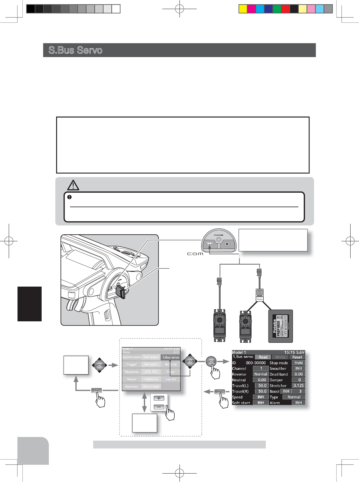
Cover
Connecting S.BUS/S.BUS2
servo connector to the trans-
mitter Communication port.
126
Function
S.Bus servo
-When the T4PX battery voltage drops, since the display switches to low battery display,
XVHWKLVIXQFWLRQLQWKHVWDWHLQZKLFKWKHUHPDLQLQJEDWWHU\FKDUJHLVVXI¿FLHQW
-Power is supplied to the servo from the transmitter, but the corresponding voltage is for
high voltage servo (HV) use. Since an overvoltage will be applied to servos other than
this, connect the corresponding battery to the servo. When the battery is connected, the
supply of power from the transmitter automatically stops.
Caution
When connecting an S-BUS servo that does not support high voltage, connect a battery
matched to the servo specifications.
High voltage servo support voltage is supplied from the transmitter. If a servo that does not support high voltage is
connected, unreasonable force will be applied to the servo and will cause trouble.
Communication port
S.Bus Servo
This is a special function which allows Futaba S.BUS/S.BUS2 servo parameter changes to
be set by the T4X transmitter.
However, some data changes require a PC and S-Link software.
This function is used by connecting
Futaba S.BUS/S.BUS2 servo
directly to the transmitter.
8VHWKHYDULRXVRSWLRQDOVHUYRH[WHQVLRQFRUGVDFFRUGLQJWRWKHGLVWDQFHEHWZHHQWKHWUDQVPLWWHU
and
servo
.
Pres
s
Pres
s
Pres
s
Pres
s
4PX-Eng-08-Function-104-156.indd 126 2014/07/18 17:36:16
127
Function
S.Bus servo
(Preparation)
- Connect the T4PX and S.BUS or S.BUS2 servo in accordance with the connection diagram
shown on page 126.
- Connect the battery to a non-high voltage(HV) support S.BUS/S.BUS2 servo.
1Turn power on the transmitter. "S.Bus servo" menu is dis-
played referring to the map of page126.
Using the S.Bus servo function
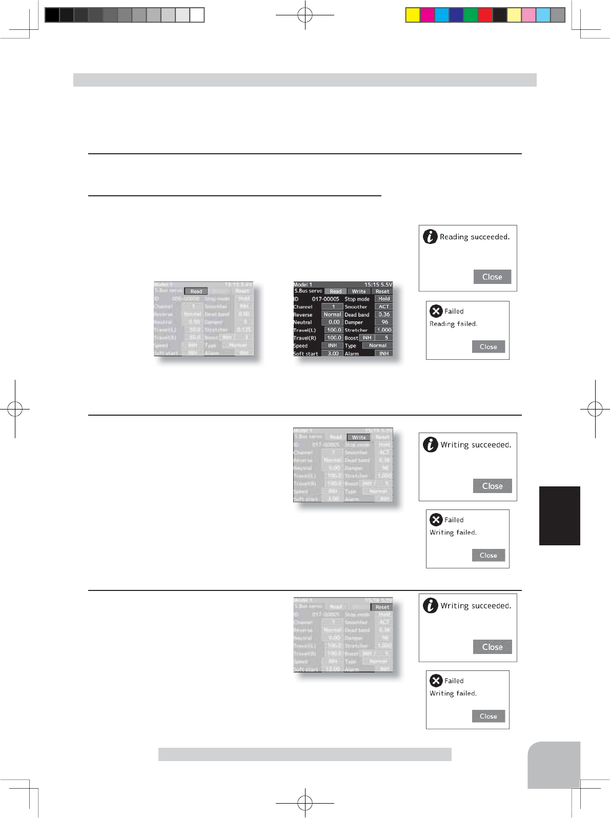
2 (S.BUS/S.BUS2 servo read)
Execute this function to read the connected servo type and
the data currently set at the servo.
-Select the setting item "Read" by (JOG) button up or down
operation, and press the (JOG) button.
-"Reading succeeded"
is displayed on the screen
and the servo’s ID cord and currently set contents are read.
- If "Faild"
is displayed on the screen
, communication with the servo is not being performed normally.
Check the T4PX and servo connection to servo and repeat "Read". (Connect the battery to a non-high voltage(HV)
support servo.)
3 (Writing to S.BUS/S.BUS2)
Execute this function to write the setting
data to servo. See pages 128~129 for
the setting data contents.
-Select the setting item "Write" by (JOG)
button up or down operation, and press
the (JOG) button.
-"
Wrieing succeeded
" is displayed on the screen and the setting data is written to
servo.
- If "Faild"
is displayed
on the screen, communication with the servo is not being per-
formed normally. Check the T4PX and servo connection to servo and repeat "Write".
(Connect the battery to a non-high voltage(HV) support servo.)
4 (Initialization)
Write the factory set servo setting data
to the connected servo and T4PX.
-Select the setting item "Reset" by (JOG)
button up or down operation, and press
the (JOG) button.
-"
Wrieing succeeded
" is displayed on the screen
and the setting data is written to servo.
-
If "Faild"
is displayed
on the screen, communication with the servo is not being
performed normally. Check the T4PX and servo connection to servo and repeat
"Write". (Connect the battery to a non-high voltage(HV) support servo.)
Setup item selection
- Select by (JOG) button up or
down operation.
Reset execution button
- (JOG) buttons pressed.
4PX-Eng-08-Function-104-156.indd 127 2014/07/18 17:36:16
128
Function
S.Bus Servo
S.BUS function setup
(Preparation)
6%866%86VHUYRLVUHDGUHIHUULQJWRWKHH[SODQDWLRQRISDJH
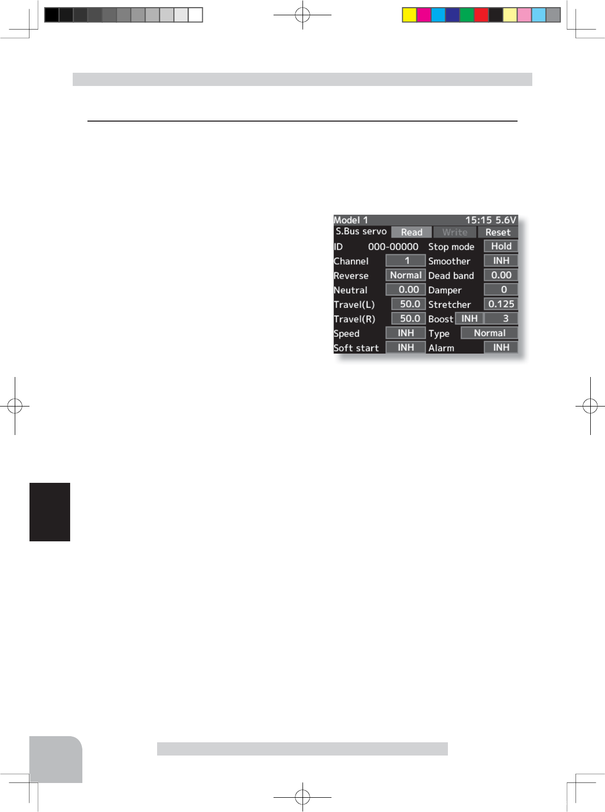
1Select the setting item by (JOG) button up, down, left, or right operation.
Set the value by (+) and (-) button.
ID
Displays the ID of the servo whose parameters are to be read. It cannot be changed.
Channel
This is the S.BUS system channel assigned to the servo. When
connected to the receiver S-BUS2 connector as an S.BUS sys-
tem, the channel used by the transmitter is assigned. When the
normal receiver channel is used, channel setting is unneces-
sary.
Reverse
The direction in which the servo rotates can be changed.
Neutral
The neutral position can be changed. When the eutral offset is
large value, the servo’s range of travel is restricted on one side.
Travel(L)
The maximum left travels centered about the neutral position
can be set independently.
Travel(R)
The maximum right travels centered about the neutral position can be set independently.
Speed
Speeds can be matched by specifying the operating speed. The speed of multiple servos can be matched without be-
ing affected by motor fluctuations. This is effective for load torques below the maximum torque.
However, note that the maximum speed will not be exceed what the servo is capable of even if the servos operating
voltage is increased.
Soft Start
Restricts operation in the specified direction the instant the power is turned on. By using this setting, the first initial
movement when the power is turned on slowly moves the servo to the specified position.
Stop Mode
The state of the servo when the servo input signal is lost can be specified. The "Hold" mode setting holds the servo in
its last commanded position even if using AM or FM system.
Smoother
This function makes servo operation smooth. Set it according to your taste. Normally set it to "ACT". Set it to "INH"
when want especially quick operation. When the smoother function was set to "ACT" and the servo was operated the
distance up to the target position is hanged in steps so movement is smooth.
Dead band
The dead band angle at stopping can be specified.
[Relationship between dead band set value and servo operation]
Small - Dead band angle is small and the servo is immediately operated by a small signal change.
Large - Dead band angle is large and the servo does not operate at small signal changes.
(Note) If the dead band angle is too small, the servo will operate continuously and the current consumption will in-
crease and the life of the servo will be shortened.
4PX-Eng-08-Function-104-156.indd 128 2014/07/18 17:36:16

129
Function
S.Bus Servo
Damper
The characteristic when the servo is stopped can be set.
When smaller than the standard value, the characteristic becomes an overshoot characteristic. If the value is larger
than the standard value, the brake is applied before the stop position.
Especially, when a large load is applied, overshoot, etc. are suppressed by inertia and hunting may occur, depend-
ing on the conditions. If hunting (phenomena which cause the servo to oscillate) occurs even though the Dead Band,
Stretcher, Boost and other parameters are suitable, adjust this parameter to a value larger than the initial value.
[Relationship between damper set value and servo operation]
Small - When you want to overshoot. Set so that hunting does not occur.
Large - When you want to operate so that braking is not applied. However, it will feel like the servo response has wors-
ened.
(Note) If used in the hunting state, not only will the current consumption increase, but the life of theservo will also be
shortened.
Stretcher
The servo hold characteristic can be set. The torque which attempts to return the servo to the target position when the
current servo position has deviated from the target position can be adjusted.
This is used when stopping hunting, etc., but the holding characteristic changes as shown below.
[Relationship between stretcher and servo operation]
Small - Servo holding force becomes weaker.
Large - Servo holding force becomes stronger.
(Note) When this parameter is large, the current consumption increases
Boost/Boost (ON/OFF)
INH : It is the boost ON at the time of low-speed operation.(In the case of usual)
ACT : It is always the boost ON.(When quick operation is hope)
The minimum current applied to the internal motor when starting the servo can be set. Since a small travel does not
start the motor, it essentially feels like the dead band was expanded. The motor can be immediately started by adjust-
ing the minimum current which can start the motor.
[Relationship between boost set value and servo operation]
Small - Motor reacts to a minute current and operation becomes smooth.
Large - Initial response improves and output torque increases. However, if the torque is too large, operation will be-
come rough.
Type
When "Retractable" is selected and the servo has been continuously stopped for 30 seconds, the dead
band expands and unnecessary hold current due to external force is eliminated. When a new control
signal enters, normal operation is resumed. When using the servo as a landing gear servo, select
"Retractable". Also adjust the servo travel to match the landing gear movement range.
Alarm
When the power supply of a servo is previously turned on at the time of a power supply injection without taking trans-
mit of a transmitter, the buzzer sound of about 2.5 Hz continues sounding from a servo.
(Even when the transmit of a transmitter is taken out previously, a buzzer becomes until the signal of a servo is output-
ted normally, but it is not unusual.)
The transmitter has been turned OFF ahead of a servo power supply The buzzer sound of about 1.25 Hz continues
sounding as servo power supply end failure alarm.
(Do not insert or remove the servo connector while the receiver power is ON. A buzzer may sound by incorrect recog-
nition.)
*Buzzer sound is generated by vibrating the motor of a servo.
Since current is consumed and a servo generates heat, please do not operate the number more than needed or do not
continue sounding a buzzer for a long time.
4PX-Eng-08-Function-104-156.indd 129 2014/07/18 17:36:16
Info
Info
Info
Info
Signal
Info
Voltage Sensor
Temperature
Sensor
RPM Sensor
Battery voltage is displayed
at the transmitter.
Power battery voltage is
displayed at the transmitter.
voltage
T-FHSS Receiver
Transmitter
Switch
Connect to S.BUS2 Connector
HUB
HUB
Connection
diagram
130
Function
-Usable sensor options(As of June 2014)
*Temperature sensor (SBS-01T) Perfect for engine head, etc.
*Temperature sensor (SBS-01TE) Used by attaching to a motor, etc.
*RPM Sensor (SBS-01RM) Measures speed over the 0 to 999,900rpm range.
*Voltage Sensor (SBS-01V) Measures external power supply voltages up to 100V.
What is a slot?
Servos are classified by channel and sensors are classified by "slot". Since the T4PX initial slot
No. is set at each sensor in advance, they can be connected as is. There are 31 slots numbered
1 to 31.
*When sensors over the initial setting (use of multiple sensors of the same type) are used, they
must be registered at the sensor menu (p.138).
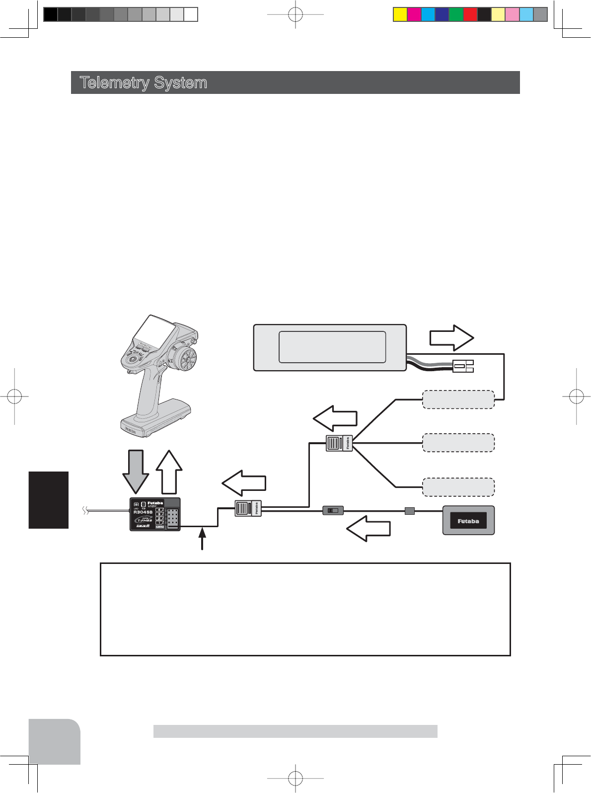
Telemetry
Telemetry System
With the telemetry system, the running status can be displayed at the transmitter and also
recorded as a data log by installing various sensor units to the chassis
(The S-FHSS and FASST systems do not have a telemetry function.)
-The sensor data can be checked at the transmitter by connecting the telemetry sensor sold
separately to the S.BUS2 connector of the R304SB receiver.
-To log this information, a start/stop switch is set by switch setting (p.99).
The log data recorded on a microSD card can be converted to CSV format by the telemetry
ORJFRQYHUWHUUHOHDVHGDWRXUKRPHSDJH:KHQFRS\LQJRUPRYLQJWKHORJ¿OHDOZD\VVHOHFW
ERWK)/,DQG)/'¿OHV
7KH¿JXUHLVDQH[DPSOHRIFRQQHFWLRQRIDWHOHPHWU\VHQVRU7KHGDWDRIXSWRWKHIROORZ-
ing 3 types of sensor and the receiver power supply voltage can be transmitted by using the
ZD\H[WHQVLRQFRUGRUGRXEOHH[WHQVLRQFRUGVROGVHSDUDWHO\
The receiver power supply can also be connected to the S.BUS2 connector or CH1~4 con-
nector. A receiver power supply voltage sensor is unnecessary.
4PX-Eng-08-Function-104-156.indd 130 2014/07/18 17:36:16
HOME
screen MENU 2
screen
or
MENU 1 screen
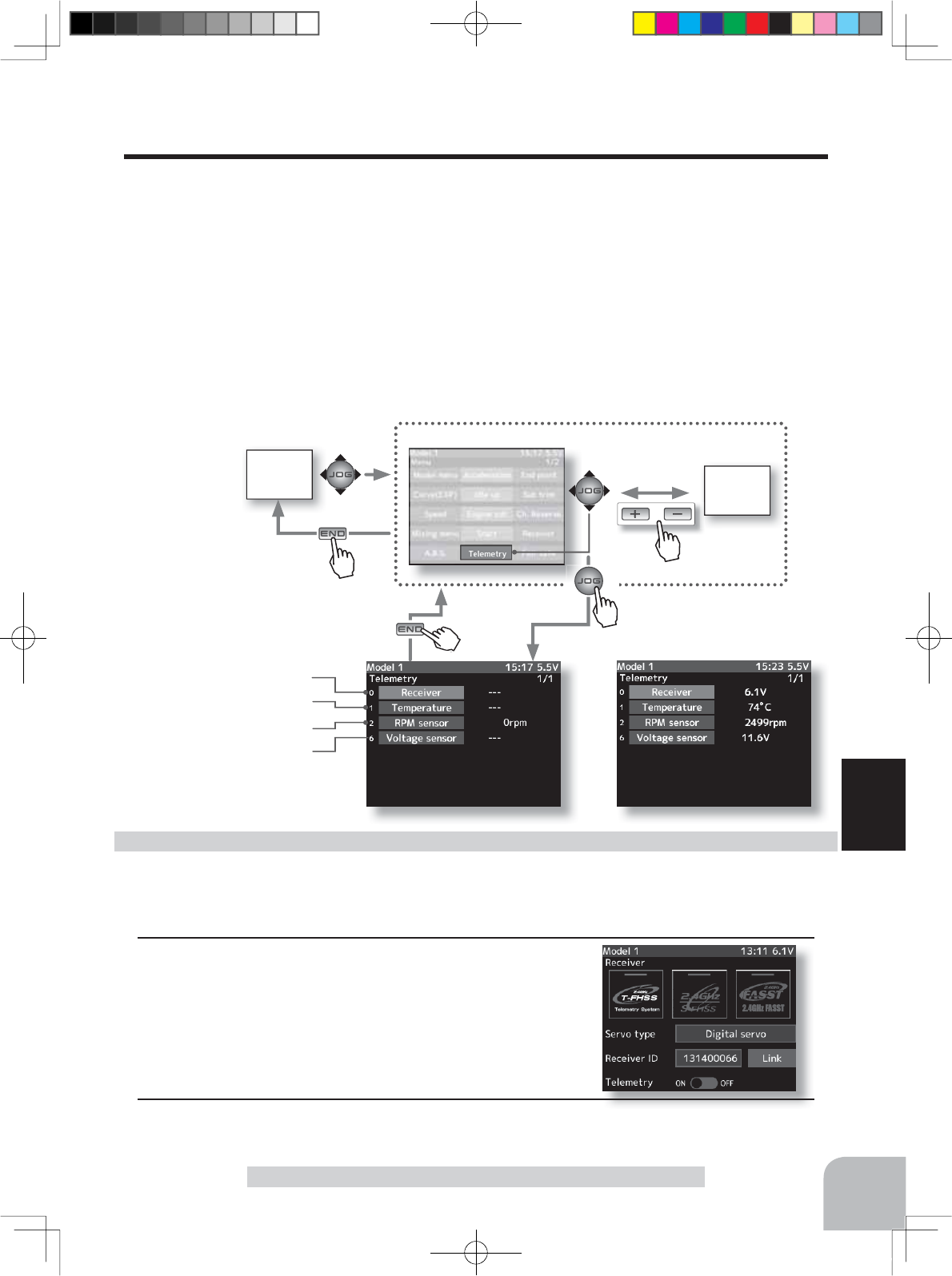
Information display
Receiver-Voltage display
Temperature display
EXT-Voltage display
RPM display
131
Function
Telemetry
Telemetry Menu
It is necessary to turn on the telemetry on the receiver setting screen to use the telemetry func-
tion. (p.46)
This screen displays and sets the various information from the receiver. An alarm and vibra-
tion can be generated depending on the information. The alarm and the vibration are set by
HDFKLQIRUPDWLRQVFUHHQ)RUH[DPSOHDGURSLQWKHYROWDJHRIWKHUHFHLYHUEDWWHU\KRXVHG
in the model car can be reported by an alarm.
The telemetry data received last is memorized. Therefore, even if the receiver power is
turned off, information display, audio guide, and alarms remain until the transmitter power
is turned off.
7KHVSHHFKIXQFWLRQFDQEHWXUQHGRQDQGRIIZLWKWKHVSHFL¿HGVZLWFK6HHWKHIXQFWLRQ
select switch function (p.99).
(Preparation)
The sensor used is connected with the receiver referring to the connection diagram of page
130.
1(Telemetry act)
The telemetry is turned on on the receiver setting screen.
(p.46)
It comes to be able to display telemetry information.
Using Telemetry function
2
When ending setting, return to the menu screen by pressing the (END) button.
Each information is described in detail beginning from page132.
Pres
s
Pres
s
Pres
s
Pre
Pres
s
4PX-Eng-08-Function-104-156.indd 131 2014/07/18 17:36:17
Telemetry screen
The voice guide loading inter-
val is set by sensor menu.
132
Function
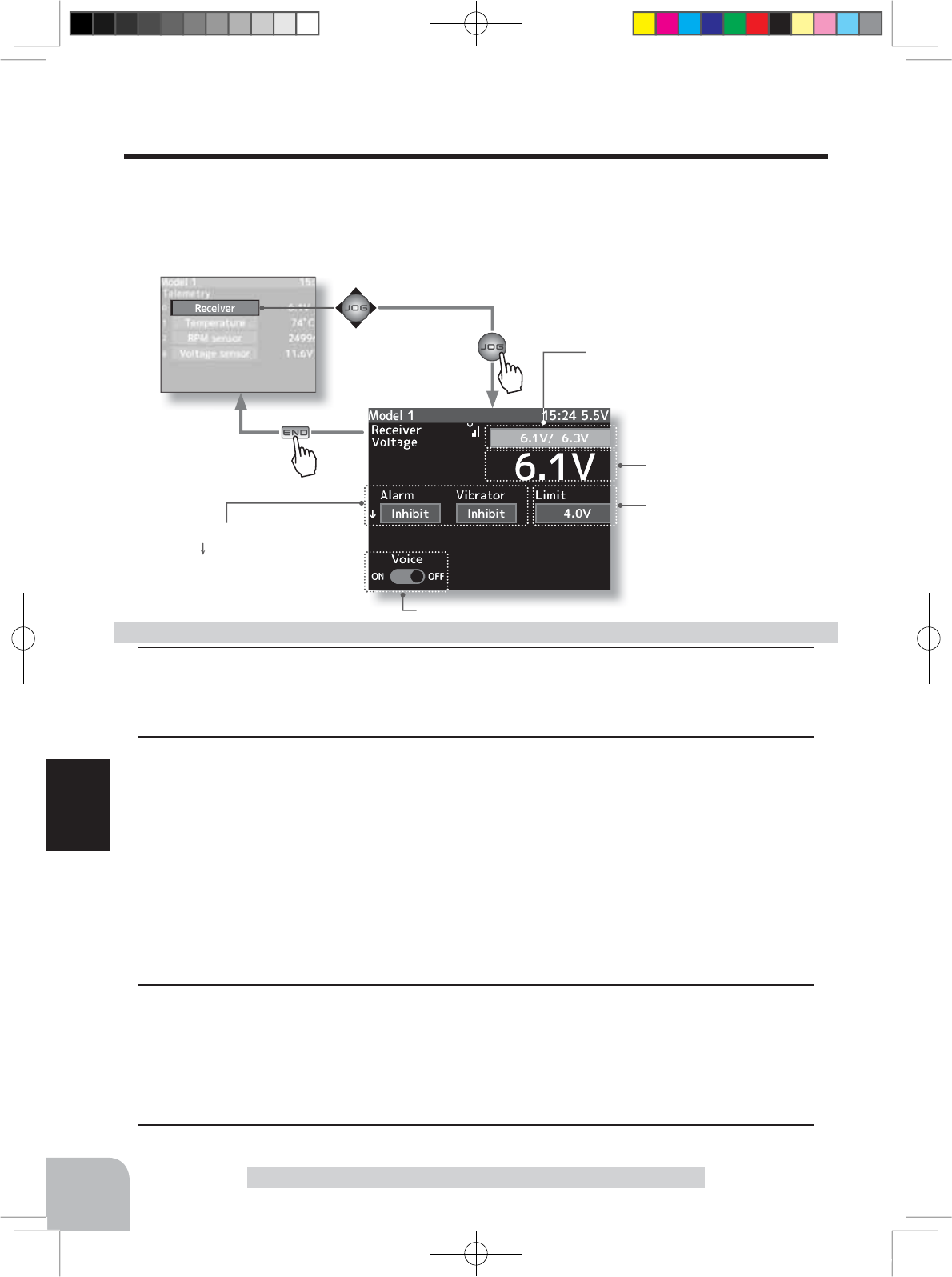
Telemetry
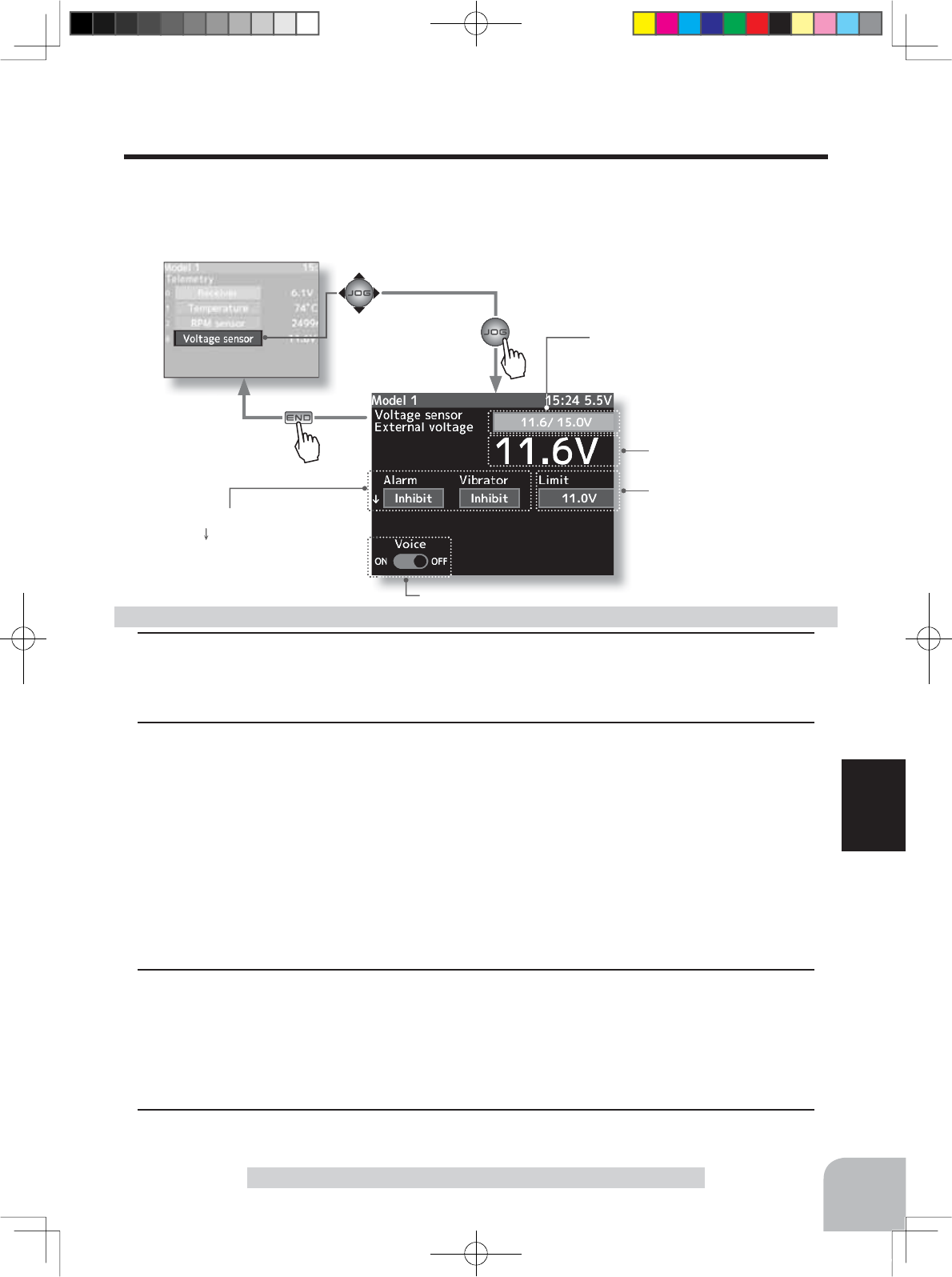
Telemetry :Receiver Battery
This function displays and sets the receiver power supply battery. The sensor sold separately
does not have to be installed. The transmitter initial state voltage is also displayed. For a
description of alarm setting when the voltage drops, see the description of the procedure on
this page.
Sets the limiter voltage
(Voltage that sounds an alarm)
The Speech function (ON/OFF)
Current receiver battery voltage
The minimum and maximum the
when powering ON are shown.
Alarm/vibrator ON/OFF and type set-
ting (The arrow indicates that an
alarm is generated when the power
supply voltage drops below the set
value.)
1(Limit adjustment)
Select the setting item "Limit" by (JOG) button up, down, left or right operation.
Use the (+) or (-) button to adjust the limit voltage.
2(Alarm and vibrator function setup)
Select the setting item "Alarm" by (JOG) button up, down, left or right operation. Set the
function to the active state by pressing the (+) or (-) button.
"Inhibit" :No audible alarm
"Buzzer" :Audible alarm
"Voice" :Voice alarm
Select the setting item "Vibrator" by (JOG) button up, down, left or right operation. Press the
(+) or (-) button and select the type.
"Inhibit" :No active vibration
"Type1" :Continuous vibration
"Type2" :Intermittent vibration for a long time
"Tyoe3" :Intermittent vibration for a short time
3(Speech function setup)
Select the setting item "Voice" by (JOG) button up,
down, left or right operation. Set the function to the ac-
tive state by pressing the (+) or (-) button.
"OFF" :No voice guide
"ON" :Information loaded by voice
4
When ending setting, return to the Telemetry menu screen by pressing the (END) button.
Alarm and Vibrator function setup
Pres
s
Pres
s
4PX-Eng-08-Function-104-156.indd 132 2014/07/18 17:36:17
Telemetry screen
The voice guide loading inter-
val is set by sensor menu.
133
Function
Telemetry
Telemetry :The Drive Battery
:LWKDQH[WHUQDOSRZHUVXSSO\RQHYROWDJHRIWKHEDWWHULHVGULYHEDWWHU\VHUYRSRZHUVXS-
ply battery, etc.) mounted separately in the chassis can be displayed at the transmitter. The
receiver S.BUS2 connector is used to connect the SBS-01Vsensor and the battery.
Sets the limiter voltage
(Voltage that sounds an alarm)
Current drive battery voltage
The Speech function (ON/OFF)
The minimum and maximum the
when powering ON are shown.
Alarm/vibrator ON/OFF and type set-
ting (The arrow indicates that an
alarm is generated when the power
supply voltage drops below the set
value.)
A drive bsttery sensor must be installed in the mod-
el car.
Install and connect the sensor in accordance with
the sensor instruction manual.
1(Limit adjustment)
Select the setting item "Limit" by (JOG) button up, down, left or right operation.
Use the (+) or (-) button to adjust the limit voltage.
2(Alarm and vibrator function setup)
Select the setting item "Alarm" by (JOG) button up, down, left or right operation. Set the
function to the active state by pressing the (+) or (-) button.
"Inhibit" :No audible alarm
"Buzzer" :Audible alarm
"Voice" :Voice alarm
Select the setting item "Vibrator" by (JOG) button up, down, left or right operation. Press the
(+) or (-) button and select the type.
"Inhibit" :No active vibration
"Type1" :Continuous vibration
"Type2" :Intermittent vibration for a long time
"Tyoe3" :Intermittent vibration for a short time
3(Speech function setup)
Select the setting item "Voice" by (JOG) button up,
down, left or right operation. Set the function to the ac-
tive state by pressing the (+) or (-) button.
"OFF" :No voice guide
"ON" :Information loaded by voice
4
When ending setting, return to the Telemetry menu screen by pressing the (END) button.
Alarm and Vibrator function setup
Pres
s
Pres
s
4PX-Eng-08-Function-104-156.indd 133 2014/07/18 17:36:17
Telemetry screen
Pres
s
Pres
s
The voice guide loading inter-
val is set by sensor menu.
134
Function
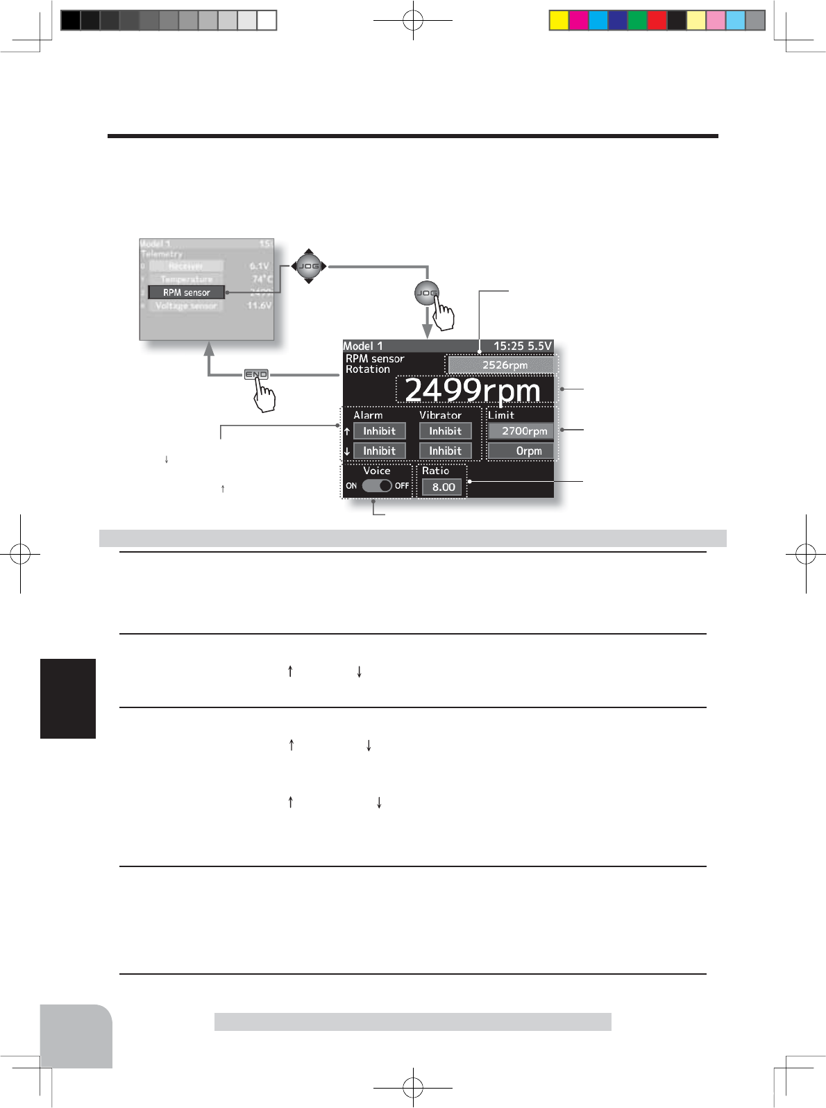
Telemetry
Current RPM
Gear ratio
Sets the limit speed
Upper limit/lower limit
(Speed that sound an alarm)
The Speech function (ON/OFF)
The maximum when powering ON are
shown.
Alarm and vibrator ON/OFF and type set-
ting (The arrow indicates that an alarm
is generated when the speed drops below
the set value and the arrow indicates that
an alarm is generated when the speed ex-
ceeds the set value.)
A RPM sensor must be installed in the model car.
Install and connect the sensor in accordance with
the sensor instruction manual.
1(Gear ratio setup)
Select the setting item "Ratio" by (JOG) button up, down, left or right operation. Use the (+)
or (-) button to adjust the lgear ratio.
2(Limit adjustment)
Select the setting item " Limit" or " Limit"by (JOG) button up, down, left or right operation.
Use the (+) or (-) button to adjust the limit voltage.
3(Alarm and vibrator function setup)
Select the setting item " Alarm" or " Alarm" by (JOG) button up, down, left or right opera-
tion. Set the function to the active state by pressing the (+) or (-) button.
"Inhibit" :No audible alarm / "Buzzer" :Audible alarm/ "Voice" :Voice alarm
Select the setting item " Vibrator" or " Vibrator" by (JOG) button up, down, left or right op-
eration. Press the (+) or (-) button and select the type.
"Inhibit" :No active vibration/ "Type1" :Continuous vibration/ "Type2" :Intermittent vibration for a long time/
"Tyoe3" :Intermittent vibration for a short time
4(Speech function setup)
Select the setting item "Voice" by (JOG) button up,
down, left or right operation. Set the function to the ac-
tive state by pressing the (+) or (-) button.
"OFF" :No voice guide/ "ON" :Information loaded by voice
5
When ending setting, return to the Telemetry menu screen by pressing the (END) button.
Alarm and Vibrator function setup
Telemetry :RPM
Speed information from an SBS-01RM (telemetry rotation sensor) sold separately is dis-
played and set at this screen. The speed of the engine, motor, etc. of the chassis while run-
ning can be viewed at the transmitter. When the speed becomes higher (lower) than the set
speed, it can be announced by an alarm and vibration.
4PX-Eng-08-Function-104-156.indd 134 2014/07/18 17:36:17
Telemetry screen
Pres
s
Pres
s
The voice guide loading inter-
val is set by sensor menu.
135
Function
Telemetry
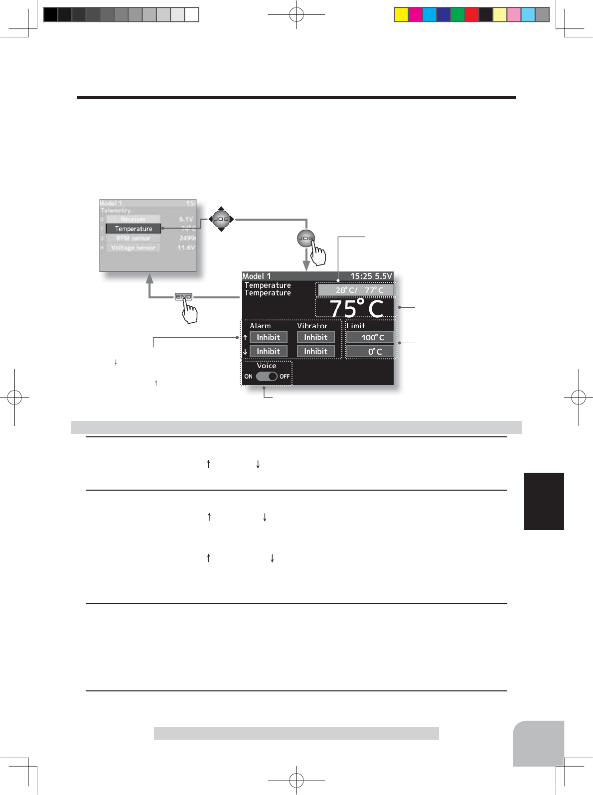
Current temperature
Limit temperature setting
(Temperature that sounds an
alarm)
The Speech function (ON/OFF)
Alarm and vibrator ON/OFF and type set-
ting (The arrow indicates that an alarm
is generated when the speed drops below
the set value and the arrow indicates that
an alarm is generated when the speed ex-
ceeds the set value.)
A temperature sensor must be installed in the model car.
Install and connect the sensor in accordance with the
sensor instruction manual.
The minimum and maximum the
when powering ON are shown.
1(Limit adjustment)
Select the setting item " Limit" or " Limit"by (JOG) button up, down, left or right operation.
Use the (+) or (-) button to adjust the limit voltage.
2(Alarm and vibrator function setup)
Select the setting item " Alarm" or " Alarm" by (JOG) button up, down, left or right opera-
tion. Set the function to the active state by pressing the (+) or (-) button.
"Inhibit" :No audible alarm / "Buzzer" :Audible alarm/ "Voice" :Voice alarm
Select the setting item " Vibrator" or " Vibrator" by (JOG) button up, down, left or right op-
eration. Press the (+) or (-) button and select the type.
"Inhibit" :No active vibration/ "Type1" :Continuous vibration/ "Type2" :Intermittent vibration for a long time/
"Tyoe3" :Intermittent vibration for a short time
3(Speech function setup)
Select the setting item "Voice" by (JOG) button up,
down, left or right operation. Set the function to the ac-
tive state by pressing the (+) or (-) button.
"OFF" :No voice guide
"ON" :Information loaded by voice
4
When ending setting, return to the Telemetry menu screen by pressing the (END) button.
Alarm and Vibrator function setup
Telemetry :Temperature
This screen displays and sets the temperature information from an SBS-01T (telemetry
temperature sensor) sold separately. The temperature of the engine, motor, amp, etc. of the
chassis while running can be viewed at the transmitter.
When the temperature becomes higher (lower) than the set value, it can be announced by an
alarm and vibration.
4PX-Eng-08-Function-104-156.indd 135 2014/07/18 17:36:18
HOME
screen
or
MENU 2 screen
Sensor menu screen Sensor list
Pus
h
MENU 1
screen
sensor
The required number of
slots The number which can be used as a start slot
TEMP(SBS-01T) 1 slot 1~31
RPM(SBS01RM) 1 slot 1~31
Voltage(SBS-01V) 2 slot 1,2,3,4,5,6,8,9,10,11,12,13,14,16,17,18,19,
20,21,22,24,25,26,27,28,29,30
Select by (JOG) button up,
down, left or right operation,
and use the (+) and (-) buttons
to make adjustments.(sec)
136
Function
6HUYRV DUH FODVVL¿HG E\ &+ EXW VHQVRUV DUH FODVVL¿HG LQ XQLWV FDOOHGVORW7KHUHDUH
slots from No. 1 to No. 31. Using a sensor which uses two or more slots, the required
number of slots is automatically assigned by setting up a start slot. When 2 or more of
the same kind of sensor are used, the sensors themselves must allocate unused slots and
memorize that slot.
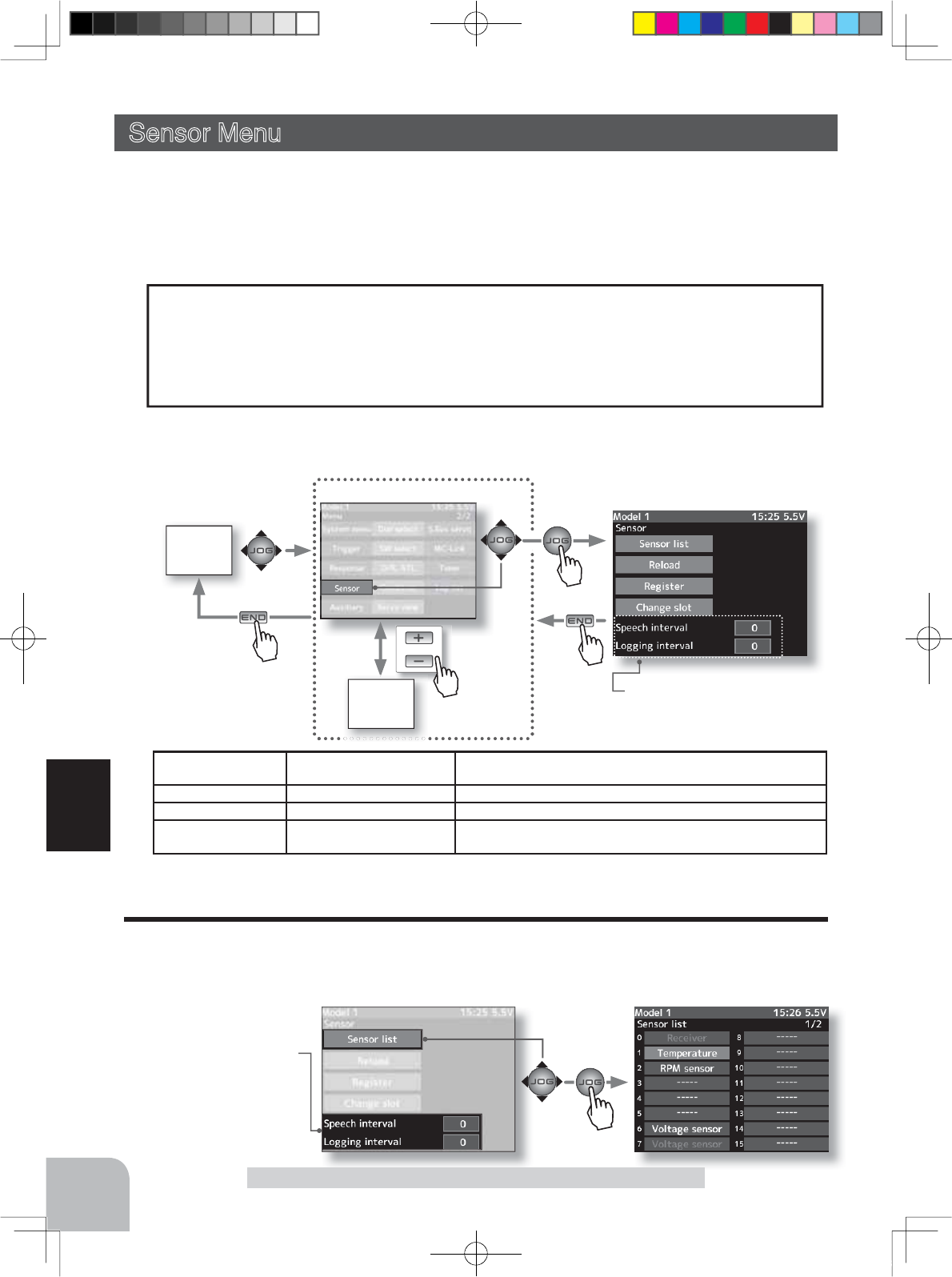
What is a slot?
Sensor Menu
The interval at which the voice guide of the telemetry information is read and the interval at
which the log data is recorded can be set at this screen.
Sensor List
The sensors registered at the T4PX are displayed. When sensor reloading, sensor registra-
tion, slot number change, etc. is performed, it is added to the list and the list is changed.
Sensor Menu
This menu registers the telemetry sensors used with the transmitter. When only one of a certain
type of sensor is used, this setting is unnecessary and the sensor can be used by simply connect-
ing it to the S.BUS2 port of the transmitter.
When using 2 or more of the same kind of sensor, they must be registered here.
Adjustment buttons
- Use the (+) and (-) buttons to
make adjustments.
- Return to the initial value by
pressing the (+) and (-) buttons
simultaneously (approx. 1 sec).
Interval
0 ~ 30sec
Initial value:0
Pres
s
Pres
s
Pres
s
Pres
s
4PX-Eng-08-Function-104-156.indd 136 2014/07/18 17:36:18
Sensor menu screen
Communication port
Sensor
Sensor
Sensor
All the sensors to be used
are connected to the T4PX.
Cover
137
Function
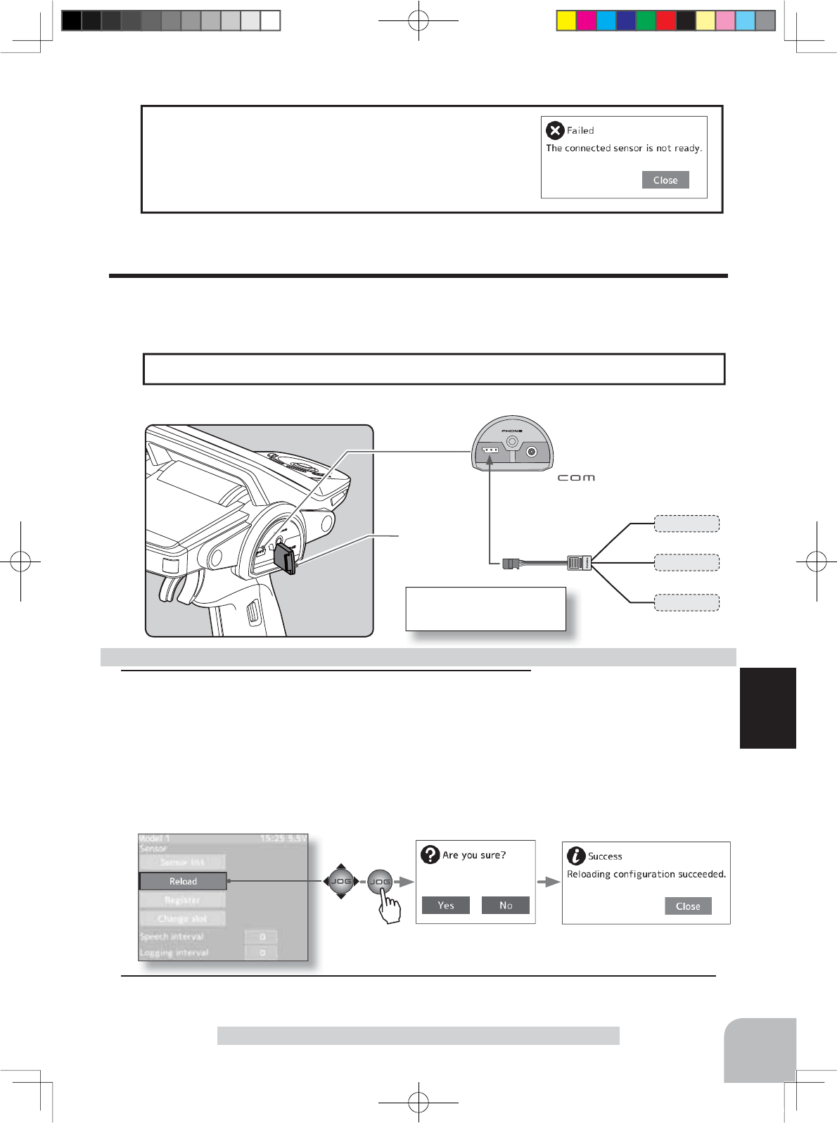
When sensor registration or slot number change was
performed and the message "Failed. The connected sen-
sor is not ready." was displayed, check the sensor con-
QHFWLRQ,IWKHVHQVRULV¿UPO\FRQQHFWHGWKHVHQVRURU
transmitter is probably faulty.
Sensor Menu
All the sensors to be used are connected to the T4PX.
Sensor Reload
This function secures contiguous unused slots by rearranging the registration state when
sensor registration and deregistration are performed repeatedly and the unused slots are
fragmented.
1(Reload)
Select "Reload" by (JOG) button up or down operation and
press the (JOG) button. The confirmation message "Are you
sure?" appears. To execute reload, select "Yes" and to cancel
reload, select "No" with the (JOG) button and press the (JOG)
button. If the message "Success" is displayed, reloading is
complete.
Sensor reload
2
When ending setting, return to the Sensor menu screen by pressing the (END) button.
Setup item selection
- Select by (JOG) button up or
down operation.
Reload button
-(JOG) buttons pressed.
Pres
s
4PX-Eng-08-Function-104-156.indd 137 2014/07/18 17:36:19
Communication port
Sensor (The battery is not necessary)
Cover
Sensor menu screen
138
Function
Sensor Menu
Connecting S.BUS/S.BUS2
servo connector to the trans-
mitter Communication port.
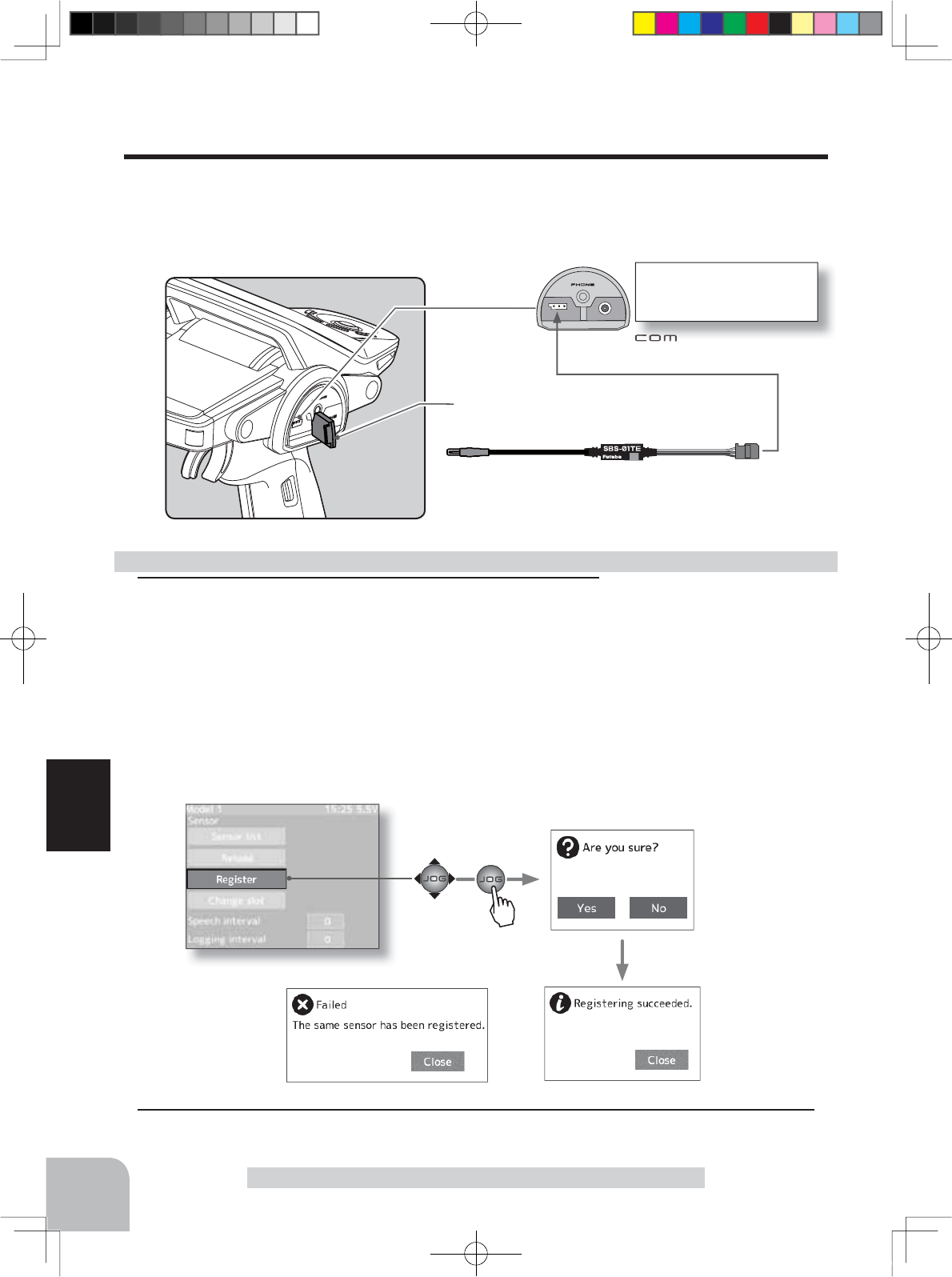
Sensor Register
7KLVIXQFWLRQUHJLVWHUVDQDGGLWLRQDOVHQVRU&RQQHFWWKHVHQVRUDVVKRZQLQWKH¿JXUHDQG
register it by the following procedure. The sensor ID is registered in the transmitter.
This function is set when using multiple telemetry sensors of the same type.
1(Register)
Select "Register" by (JOG) button up or down operation and
press the (JOG) button. The confirmation message "Are you
sure?" appears. To execute registration, select "Yes" and to
cancel registration, select "No" by (JOG) button and press the
(JOG) button. If registering a sensor that has already been
registered is attempted, the message "Failed" will be dis-
played.
Sensor register
2
When ending setting, return to the Sensor menu screen by pressing the (END) button.
Setup item selection
- Select by (JOG) button up or
down operation.
Register button
- (JOG) buttons pressed.
Pres
s
4PX-Eng-08-Function-104-156.indd 138 2014/07/18 17:36:19
Sensor menu screen
139
Function
Sensor Menu
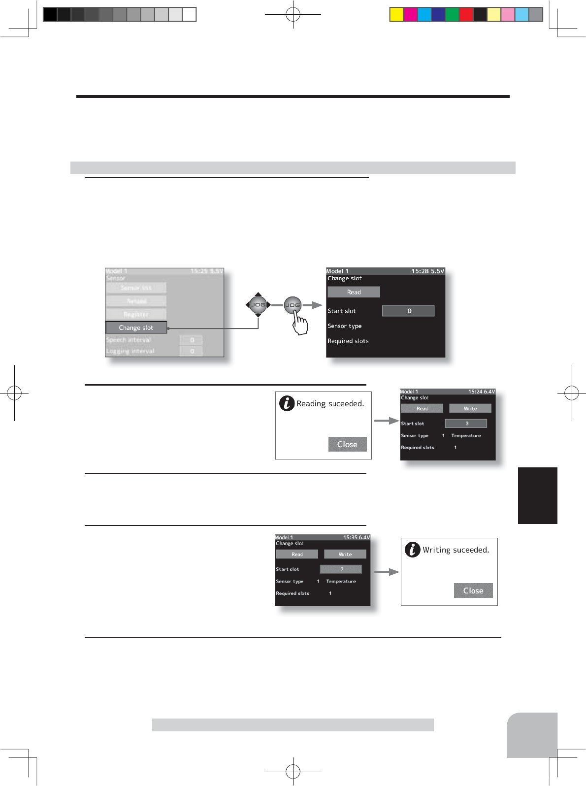
Change Slot
This procedure changes the slot number of one registered sensor. Connect the sensor as
VKRZQLQWKH¿JXUHSDQGFKDQJHVORWQXPEHULWE\WKHIROORZLQJSURFHGXUH
This function is set when using multiple telemetry sensors of the same type.
1(Change)
Select "Slot No. change" by (JOG) button up or down opera-
tion and press the (JOG) button. A sensor details screen is
displayed.
Sensor slot change
2Select "Load" by (JOG) button up
or down operation and press the
(JOG) button. The message "Reading
suceeded" appears and the current
sensor information is displayed.
Setup item selection
- Select by (JOG) button up or
down operation.
Select button
- (JOG) buttons pressed.
3Select "Slot No." by (JOG) button up or down operation and
set the new number by pressing the (+) or (-) button.
4Select "Write" by (JOG) button up or
down operation and press the (JOG)
button. The message "Settings writ-
ten" appears and number change is
complete.
Pres
s
5
When ending setting, return to the Sensor menu screen by pressing the (END) button.
4PX-Eng-08-Function-104-156.indd 139 2014/07/18 17:40:19
HOME
screen
or
MENU 2 screen
MENU 1
screen
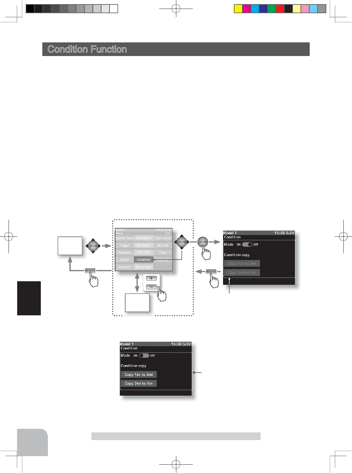
When the condition function is
turned on, the condition copy display
becomes active and the condition is
enabled.
140
Function
Condition Function
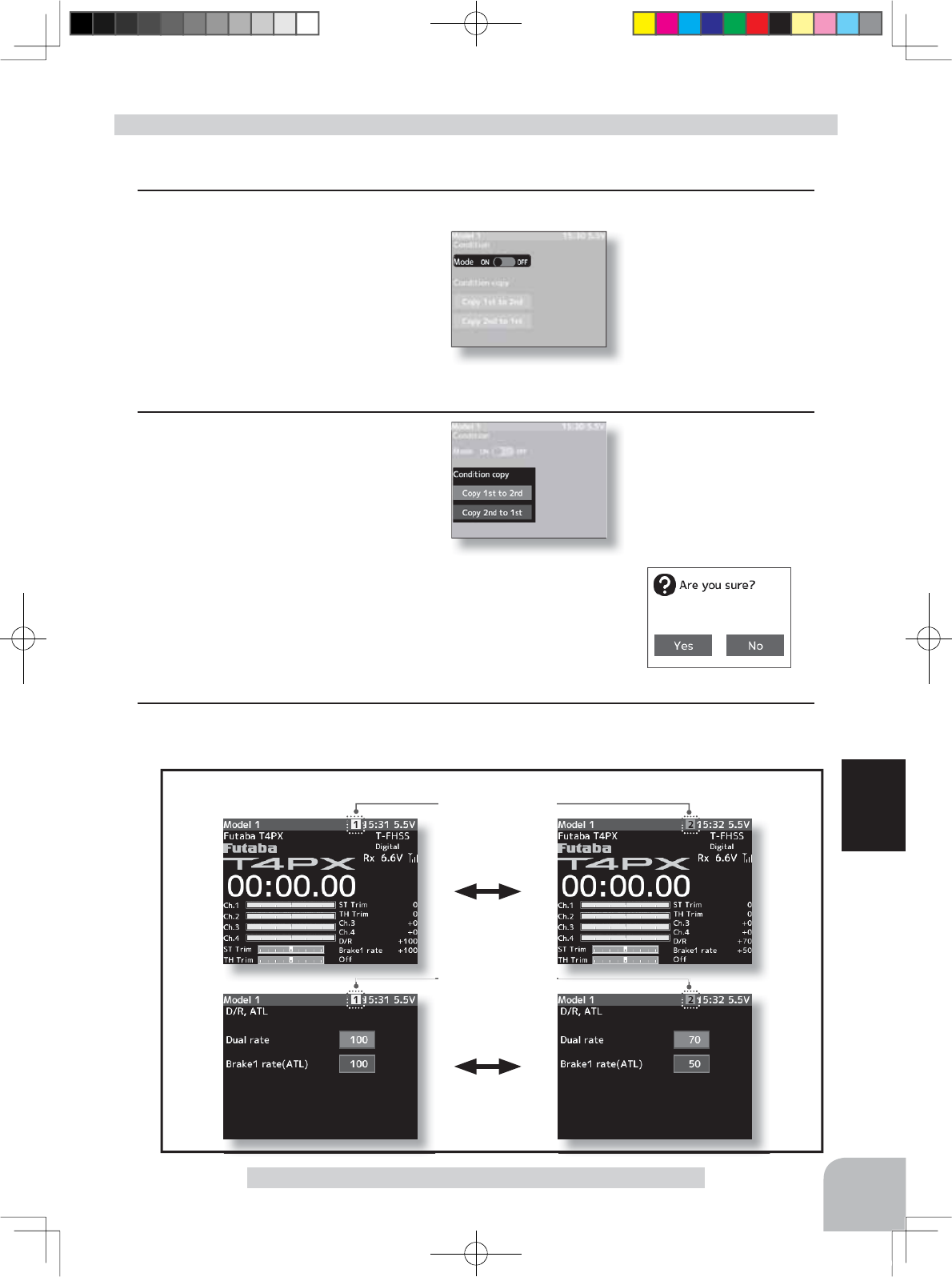
7ZR NLQGV RI GDWD FDQ EH VHW LQ RQH PRGHO IRU VSHFL¿F IXQFWLRQVRQO\IRUH[DPSOHWZR
kinds of data such as steering D/R set to 90% at normal condition and steering D/R set to
80% at second condition. This second condition can be set for each model.
-The functions that can be set at each condition are displayed by condition number at the top
of the menu screen. Since the reverse function, end point and other model standard setup
menus are not displayed by conditioner number, the condition 1 and condition 2 settings are
common.
- To use the condition function, switch setting by function select switch (p.99) is necessary.
- Switching from normal condition to second condition by switch set by function select
switch is indicated by an audible alarm, and the condition number is displayed in the upper
on the screen.
-First, the initial settings of each condition 2 function are created.
-The data set at condition 2 is memorized until reset by model reset (p.116). The data is
memorized even if the condition function is turned off or setting of the SW by switch set-
ting function is changed.
Condition Function
Setting item
Mode(fubction ON/OFF)
Condition copy
Pres
s
Pres
s
Pres
s
Pres
s
4PX-Eng-08-Function-104-156.indd 140 2014/07/18 17:36:20
HOME screen
Example
D/R, ATL screen
Function ON/OFF (Mode)
ON,OFF
Setup item selection
- Select by (JOG) button up, or
down operation.
Setup buttons
- Use the (+) or (-) buttons to
make setup.
Copy selection
- Select by (JOG) button up, or
down operation.
Setup buttons
- (JOG) buttons pressed.
141
Function
Condition Function
Display when condition is used
Condition number
Condition number
(Preparation)
- Use the function select switch function to select the switch. (p.99)
1
(Function ON/OFF)
Select the setting item "Mode" by (JOG)
button up or down operation. Set the
function to the active state by pressing
the (+) or (-) button.
"OFF" :Function OFF
"ON" :Function ON
Condition copy display becomes active and the condition can be used.
2(Condition copy ON/OFF)
Select the condition copy direction
by (JOG) button up or down operation.
When copying from condition copy 1
to condition copy 2, select "2nd to 1st",
and press the (JOG) button.
The confirmation message "Are you sure?" appears. To ex-
ecute copy, select "Yes" and to cancel copy, select "No" and
press the (JOG) button.
Condition setup
3
When ending setting, return to the menu screen by pressing the (END) button.
4PX-Eng-08-Function-104-156.indd 141 2014/07/18 17:36:20
HOME
screen
or
MENU 2 screen
MENU 1
screen
Setup item selection
- Select by (JOG) button up, or
down operation.
Setup buttons
- Use the (+) or (-) buttons to
make setup.
Adjustment buttons
- Use the (+) and (-) buttons to
make adjustments.
- Return to the initial value by
pressing the (+) and (-) buttons
simultaneously (approx. 1 sec).
Rete:
1 ~ 50
142
Function
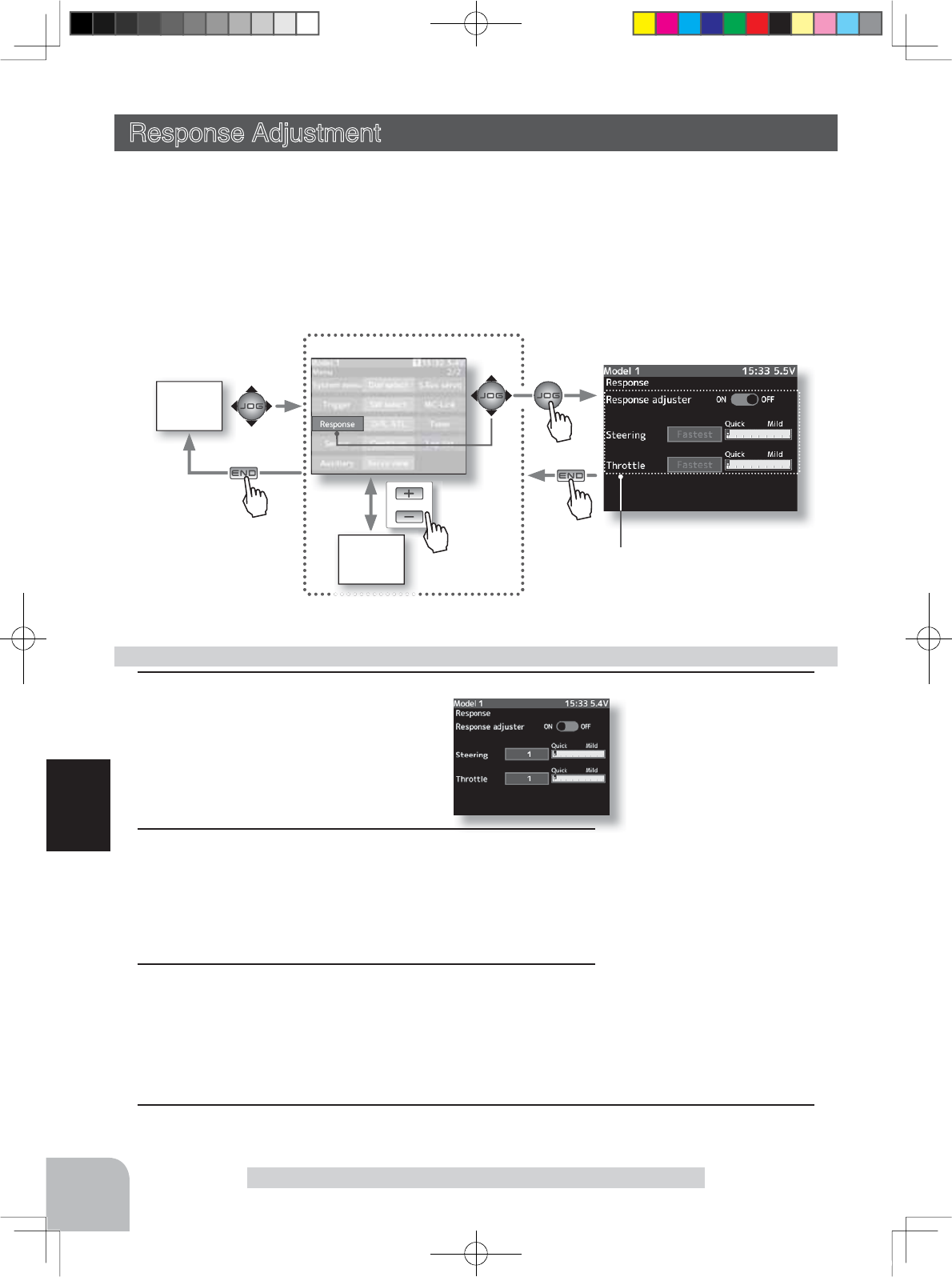
Response Adjustmen
Response Adjustment
The operation response can be adjusted to your preference and the steering and throttle can
be individually adjusted in 50 steps to match the course and vehicle.
Basically, the standard fastest response is recommended. However, use this function when
you want to change the response feeling. When this function is turned on, both the steering
and throttle are switched from the standard fastest response to step 1 mild direction setting.
The steering and throttle can be separately adjusted up to 50 steps in the mild direction
based on this.
Setting item
Respons adjuster(fubction ON/OFF)
Steering response
Throttle response
1
(Function ON/OFF)
Select the setting item "Response
adjuster" by (JOG) button up or down
operation. Set the function to the active
state by pressing the (+) or (-) button.
Response adjustment
2(Steering response)
Select the "Steering" to be set by (JOG) button operation.
When you want to milder steering response, use the (+) but-
ton to adjust the "+" side. When you want to make steering
operation quicken use the (-) button to adjust the "-" side.
3(Throttle response)
Select the "Throttle" to be set by (JOG) button operation.
When you want to milder throttle response, use the (+) but-
ton to adjust the "+" side. When you want to make steering
operation quicken use the (-) button to adjust the "-" side.
4
When ending setting, return to the menu screen by pressing the (END) button.
Pres
s
Pres
s
Pres
s
Pres
s
4PX-Eng-08-Function-104-156.indd 142 2014/07/18 17:36:20
HOME
screen
or
MENU 2 screen
MENU 1
screen
143
Function
Response Adjustment
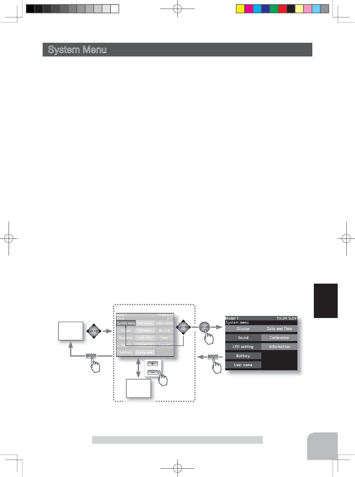
System Menu
The graphic liquid crystal screen display mode, sound, LED setting, date/time, user name,
battery mode, calibration can be set and infomation.
The system function setup items cannot be set for each model. (Second condition can be set
for each model.)
- Display
Liquid crystal screen backlighting display mode setup.
(OFF, ON at button operation, normally ON)
- Sound
Buzzer, soeech vouce sound volume adjustment.
- LED setting
LED display setup.
(OFF, Link to LCD screen backlight setting)
- Battery
Select the battery alarm voltage according to the battery to be used.
Battery type setting (LiFe 2cells, NiMH 5cells, Other)
- User name
This function allows you to assign a 15 character to user name
.
- Data and Time
Setting at date and time/ Setting of either time or total timer on HOME screen.
- Calibrattion
Use this function when a mechanical offset has occurred for some reason.
- Information
System program version information, and selection of language.
Pres
s
Pres
s
Pres
s
Pres
s
4PX-Eng-08-Function-104-156.indd 143 2014/07/18 17:36:21
System menu
Setup item selection
- Select by (JOG) button up, or
down operation.
buttons
-Setup /Adjustment buttons
- Use the (+) and (-) buttons to
make adjustments.
- Return to the initial value by
pressing the (+) and (-) buttons
simultaneously (approx. 1 sec).
144
Function
HOME
screen
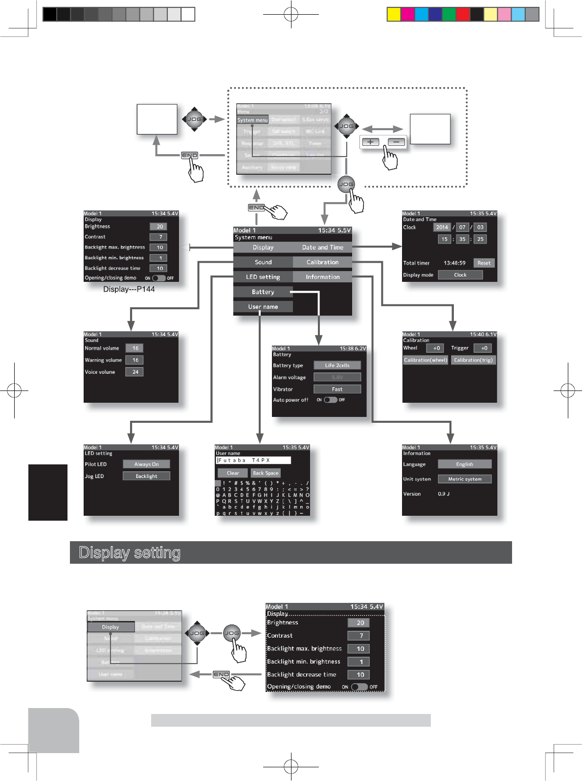
System menu/Display setting
MENU 1
screen
or
MENU 2 screen
Sound---P146
LED setting---P147 User name---P149 Information---P151
Battery---P148
Calibrattion---P152
Data and Time---P150
Display---P144
Each set screen is displayed from the system menu. Please refer to the following maps.
This setting is displayed from the screen of the system menu. (above figure)
Display setting
Brightness, contrast and back light mode adjustment LCD screen.
Pres
s
Pres
s
Pres
s
Pres
s
Pre
Pres
s
Pre
Pres
s
4PX-Eng-08-Function-104-156.indd 144 2014/07/18 17:36:21

145
Function
Display setting
1(Adjusting the crystal brightness)
Select the "brightness" to be set by (JOG) button operation,
and use the (+) and (-) buttons to adjust the screen
brightness
.
2
(Adjusting the liquid crystal contrast)
Select the "Contrast" to be set by (JOG) button operation,
and use the (+) and (-) buttons to adjust the screen contrast.
3
(Backlight decrease brightness adjustment)
Select the "Backlight max, brightness" or "Backlight man,
brightness" to be set by (JOG) button operation,
Adjust the backlight decrease brightness with the
(+) and (-)
buttons.
4
(Backlight decrease time)
You can set a time period to decrease the LCD backlight.
This function counts the period that the touch panel has been
not operated. This time can be set by one second steps. You
can also turn off the backlight decrease if you like.
Select the "Backlight decrease time", to be set by (JOG)
button operation, and
use the (+) and (-) buttons to adjust the
backlight decrease time
.
5
(Setting of Opening/closing demo)
Whether or not the Futaba T4PX logo appears on the screen
at starting and ending can be set. When set to OFF, the logo
is not displayed.
Select the "Opening/closing screen" to be set by (JOG) but-
ton operation,
and use the (+) and (-) buttons to select the dis-
play mode.
6
When ending setting, return to the system menu screen by
pressing the (END) button.
Display setup
Brightness
0~63
Initial value: 20
Contrast
0~15
Initial value: 8
Backlight decrease brightness
0~20
Initial value: max-10,min-1
Backlight decrease time
NH,1~240 sec
Initial value: max-10,min-1
Demo csreen
ON/OFF
Initial value:ON
4PX-Eng-08-Function-104-156.indd 145 2014/07/18 17:36:21
System menu
Setup item selection
- Select by (JOG) button up, or
down operation.
-Adjustment buttons
- Use the (+) and (-) buttons to
make adjustments.
- Return to the initial value by
pressing the (+) and (-) but-
tons simultaneously (approx.
1 sec).
Setup item
Normal volume (key,trim)
Warning
Voice volume
146
Function
Sound setting
This setting is displayed from the screen of the system menu. (p.144)
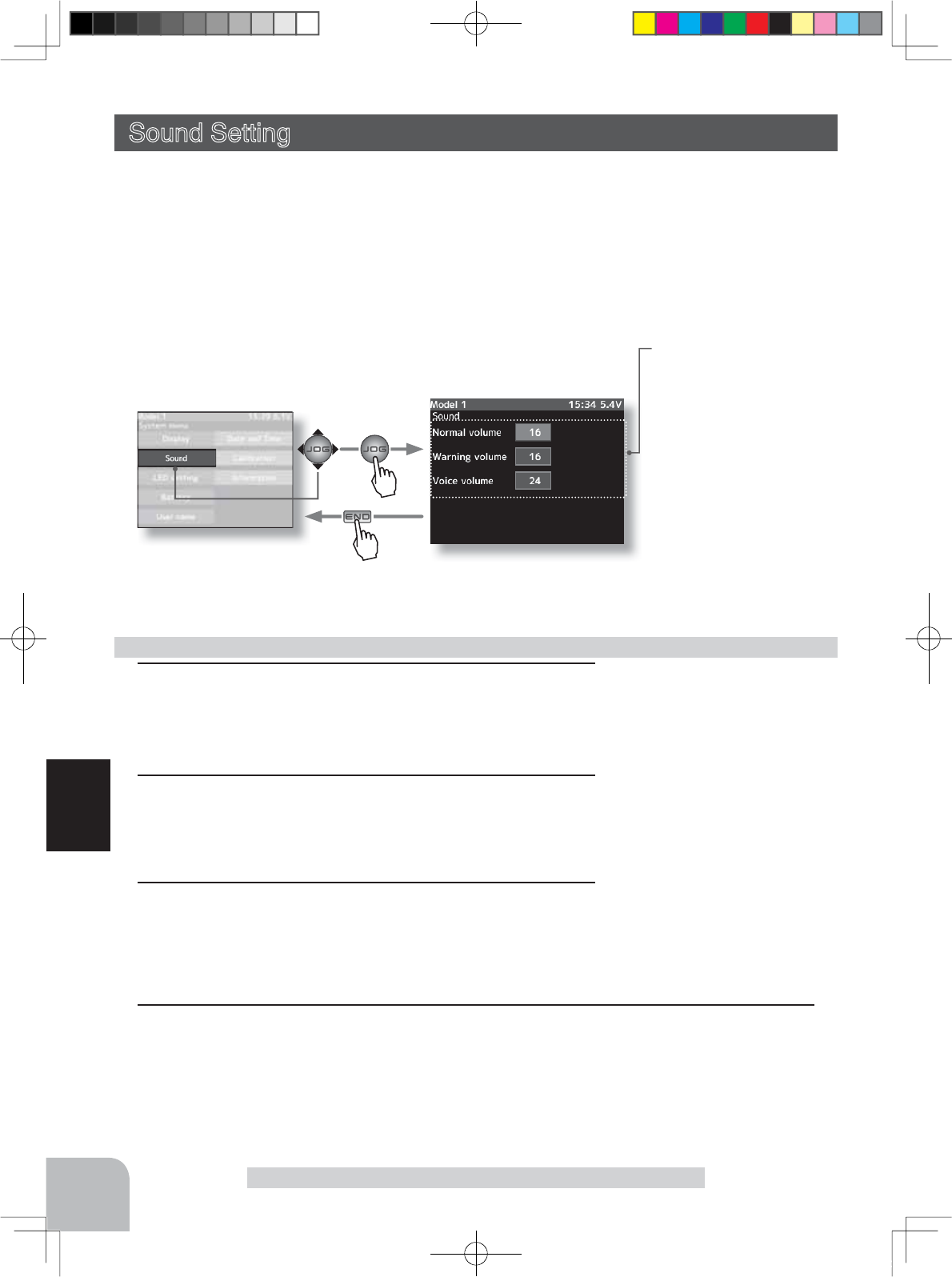
Sound Setting
7KLVIXQFWLRQFDQVHWWKHYROXPHRI.H\2SHUDWLRQ:DUQLQJDQG7HOHPUWRU\VSHHFK
LQIR
-The volume of the click when edit key, jog, and trim are operated can be adjusted.
-The volume of the audible alarm sound can be adjusted.
-When the telemetry function is used, the volume of the voice that announces the tempera-
WXUHVSHHGYROWDJHDQGRWKHULQIRUPDWLRQDWD¿[HGLQWHUYDOFDQEHDGMXVWHG
1(Adjusting the key operetion volume)
Select the "Normal volume" to be set by (JOG) button opera-
tion,
and use the (+) and (-) buttons to adjust the volume.
2
(Adjusting the warning volume)
Select the "Warning volume" to be set by (JOG) button op-
eration,
and use the (+) and (-) buttons to adjust the volume.
3
(Adjusting the voice volume)
Select the "Voice volume" to be set by (JOG) button opera-
tion,
and use the (+) and (-) buttons to adjust the volume.
Volume adjustment
Normal volume
0~32
Initial value: 16
Voice volume
0~32
Initial value: 16
Warning volume
1~32
Initial value: 16
4
When ending setting, return to the system menu screen by pressing the (END) button.
Pres
s
Pres
s
4PX-Eng-08-Function-104-156.indd 146 2014/07/18 17:36:22
System menu
Setup item
Pilot LED
Jog LED
Setup item selection
- Select by (JOG) button up, or
down operation.
-Setup buttons
- Use the (+) and (-) buttons to
make setup.
147
Function
LED setting
This setting is displayed from the screen of the system menu. (p.144)
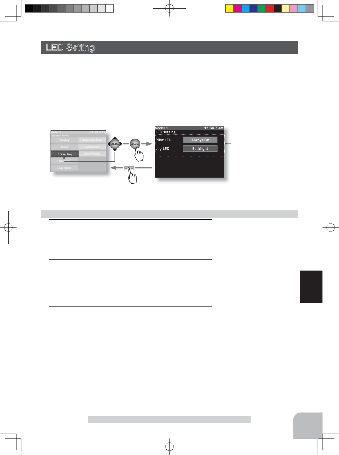
LED Setting
The method of lighting the pilot LED light and job LED light can be adjusted.
-Pilot LED always on, off.
-Jog LED always on, off, linked with backlighting.
1(Setting pilot LED)
Select the "Pilot LED" to be set by (JOG) button operation,
and use the (+) and (-) buttons to select the LED mode.
2
(Setting Jog LED)
Select the "Jog LED" to be set by (JOG) button operation,
and use the (+) and (-) to select the LED mode.
3
When ending setting, return to the system menu screen by
pressing the (END) button.
LED setting
Pilot LED mode
Always On, OFF
Jog LED mode
Backlight, Always On, OFF
Pres
s
Pres
s
4PX-Eng-08-Function-104-156.indd 147 2014/07/18 17:36:22
Setup item
Battery type
Alarm voltage
Vibrator
Auto powar off
Setup item selection
- Select by (JOG) button up, or
down operation.
-Setup buttons
- Use the (+) and (-) buttons to
make setup.
148
Function
System menu
Battery setting
This setting is displayed from the screen of the system menu. (p.144)
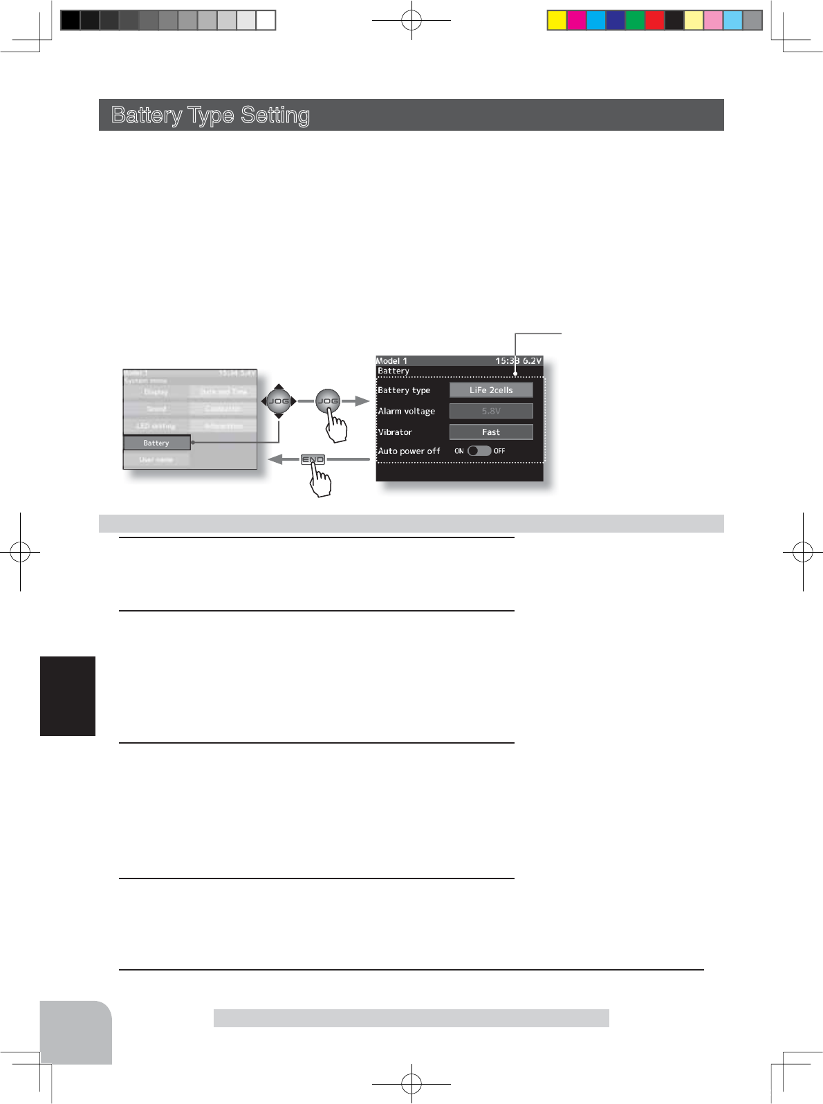
Battery Type Setting
With the T4PX, the low battery alarm setting is different, depending on the type of battery.
Therefore, always set the battery type matched to the power supply to be used. When using
D)XWDEDUHFKDUJHDEOHW\SHEDWWHU\DOZD\VVHOHFW/L)HFHOOVRU1L0+FHOOV". Incorrect
setting will substantially shorten the time from low battery alarm to system stopping and is
very dangerous.
([FHSWLRQDOO\ZKHQXVLQJDEDWWHU\RWKHUWKDQWKLVVHOHFW"Other" and set the low battery
alarm voltage on your own responsibility. Futaba is not responsible for trouble caused by
XVHRIDQXQVSHFL¿HGEDWWHU\
1(Select battery type)
Select the "Battery type" to be set by (JOG) button operation,
and use the (+) and (-) buttons to select the attery type.
2
(Setting low bwttery alarm voltage)
When a specified battery was set by battery type, the alarm
voltage is automatically set and cannot be adjusted. When
"Other" was set by battery type, set the alarm voltage your-
self. Select the "Alarm voltage" to be set by (JOG) button op-
eration,
and use the (+) and (-) to adjust the volutage.
3(Select vibrator type)
Select the "Vibrator" to be set by (JOG) button operation,
and
use the (+) and (-) buttons to select the Vibrator type.
Select the vibrator type from among Inhibit, Continuous,
Slow, and Fast. When vibration is not linked with the battery
alarm, select "Inhibit".
4(Auto power off sertting )
Select the "Auto power of" to be set by (JOG) button opera-
tion. Set the function to the active state by pressing the (+) or
(-) button.
Battery setting
Battery type
LiFe 2cells, NiMH 5cells, Other
Alarm voltagre (Other battery)
4.2V~8.0V
Initial value: 4.2V
Vibrator tyape
Inhibit, Continuous, Slow, Fast
Auto power off
ON, OFF
5
When ending setting, return to the system menu screen by pressing the (END) button.
Pres
s
Pres
s
4PX-Eng-08-Function-104-156.indd 148 2014/07/18 17:36:22
149
Function
System menu
User name
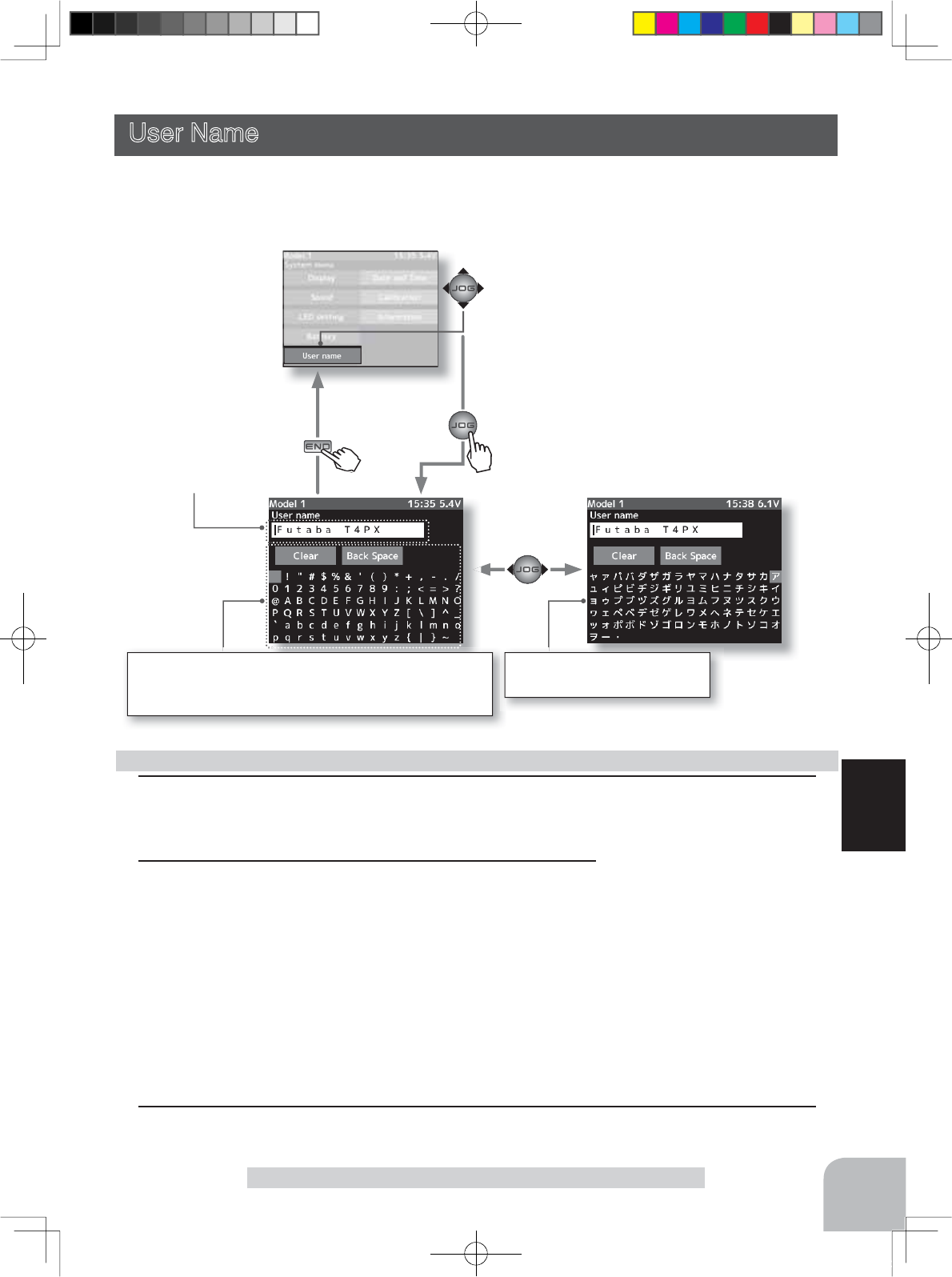
User Name
This function allows you to assign a 15 character name to each user name.
User name
This setting is displayed from the screen of the system menu. (p.144)
Pres
s
1 (Moving the cursor to the character you want to change.)
"Move the cursor to the user name character you want to set or change by pressing the (+)
or (-) button. The selected character blinks.
Setting the user name
Character select/set button
- Select the character by (JOG)
button up, down, left, or right
operation and enter the char-
acter by pressing the (JOG)
button.
Select the character with the (JOG) button.
Clear:All characters of the model name are deleted.
Back Space:The character at the left of the cursor is deleted.
"Katakana" of the Japanese
character is displayed on page 2.
2 (Selecting the character to be used)
Move the cursor by (JOG) button up, down, left, or right
operation, and select the characters to be used from the
character list at the bottom of the screen. After deciding the
characters to be used, press the (JOG) button. The charac-
ters are selected and the user name character string moves
to the right. When "Back space" on the center row is selected
and the (JOG) button is pressed, the character at the left of
the vertical cursor is deleted. When "Clear" is selected and
the (JOG) button is pressed, all the characters are deleted.
3When ending setting, return to the
system
menu screen by pressing the (END) button.
Pre
Pres
s
4PX-Eng-08-Function-104-156.indd 149 2014/07/18 17:36:22
System menu
Setup item
Clock
Total timer
Display mode
Setup item selection
- Select by (JOG) button up, or
down operation.
-Setup buttons
- Use the (+) and (-) buttons to
make setup.
150
Function
Total timer or clock display
Initial value: Clock
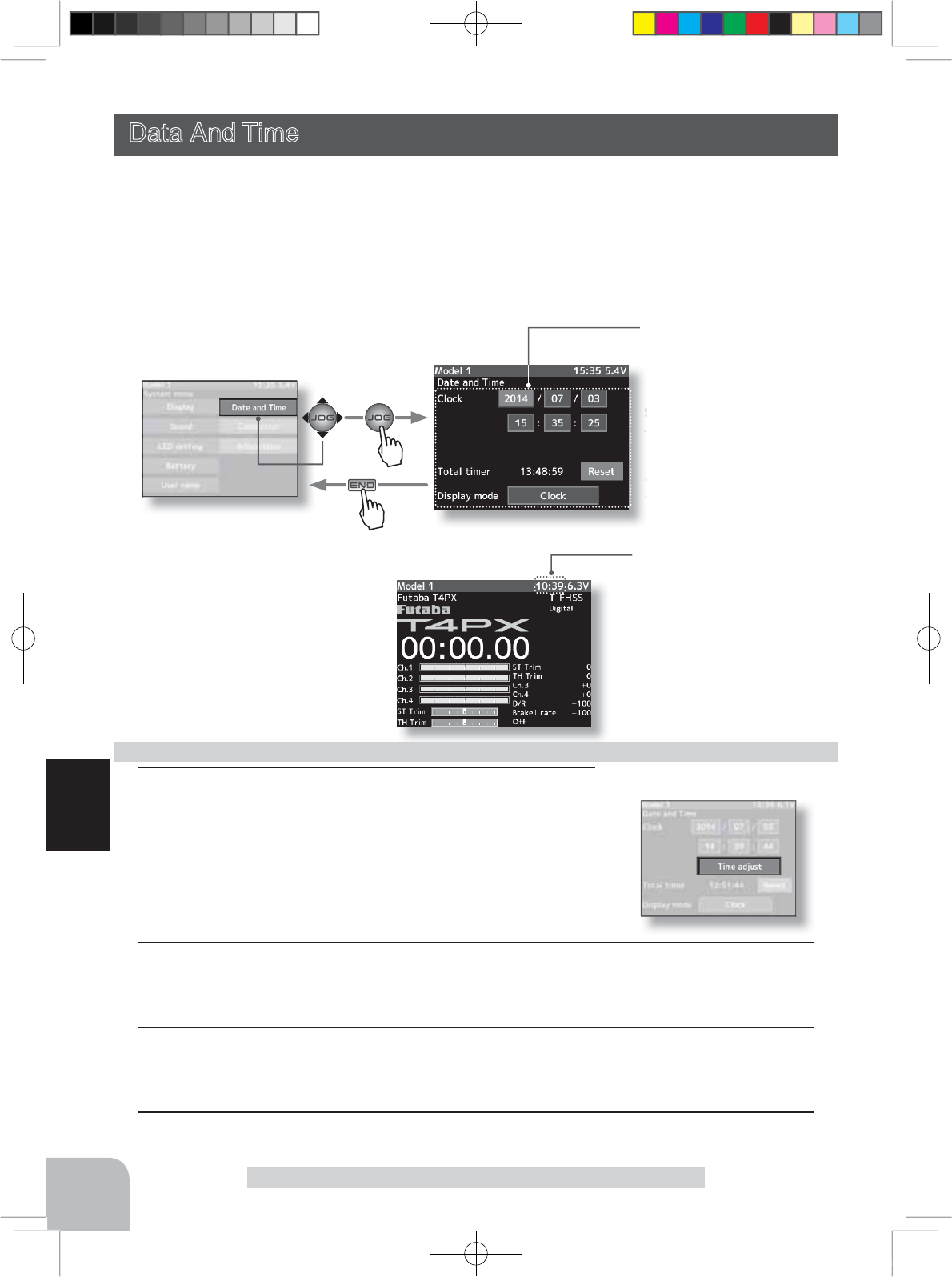
Data and Time
Data And Time
This function adjusts the system clock of the T4PX transmitter. Perform this setting when
you purchase the set and when adjustment is necessary.
Whether the time or the total timer (accumulation timer) is displayed on the initial screen
can be set. The total timer can be reset at this menu. When the total timer is displayed on
the initial screen, it can also be reset at the initial screen.
1(Date and time setting)
Select the "Year", "Month", "Day", "Hour", "Minute" or "Sec-
ond" to be set by (JOG) button operation,
and use the (+) and
(-) buttons.
Select "Time adjust" by (JOG) button up, down, left, or right
operation, and press the (JOG) button. The system clock is
updated.
Date and time setting
2
(Total tome reset)
Select the "Reset" to be set by (JOG) button operation,
and press the
(JOG) button
. The total
time is reset.
3(Select Display mode)
Select the "Display mode" to be set by (JOG) button operation,
and use the (+) and (-) but-
tons to select the
Display mode
4
When ending setting, return to the system menu screen by pressing the (END) button.
Pres
s
Pres
s
This setting is displayed from the screen of the system menu. (p.144)
4PX-Eng-08-Function-104-156.indd 150 2014/07/18 17:36:23
System menu
Menu screen of Japanese Menu screen of German
Setup item
Language
Unit system
Version
Setup item selection
- Select by (JOG) button up, or
down operation.
151
Function
Information
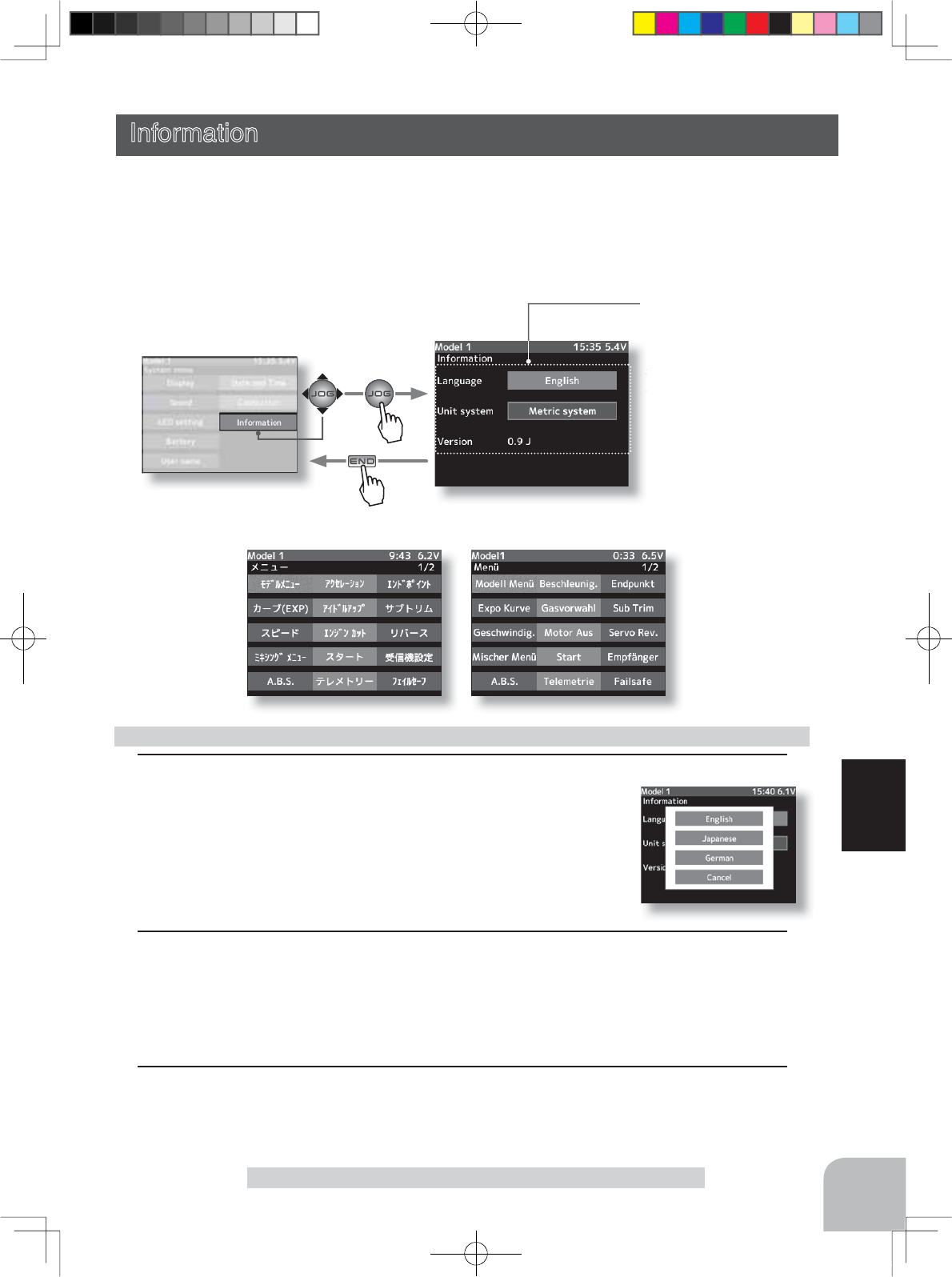
System program version information, and selection of language.
Infomation
Information
1 (Language setting)
Select "Language" by (JOG) button up operation and press the
(JOG) key. A list of languages appears on the screen. Select
"English", "Japanese", or "German" by (JOG) button up or down
operation and press the (JOG) button. The language changes.
2(Units system setting)
Select "Units system" by (JOG) button up or down operation and select the metric sys-
tem or yard and pound system by pressing the (+) or (-) button.
3
When ending setting, return to the system menu screen by pressing the (END) button.
This setting is displayed from the screen of the system menu. (p.144)
Pres
s
Pres
s
4PX-Eng-08-Function-104-156.indd 151 2014/07/18 17:36:23
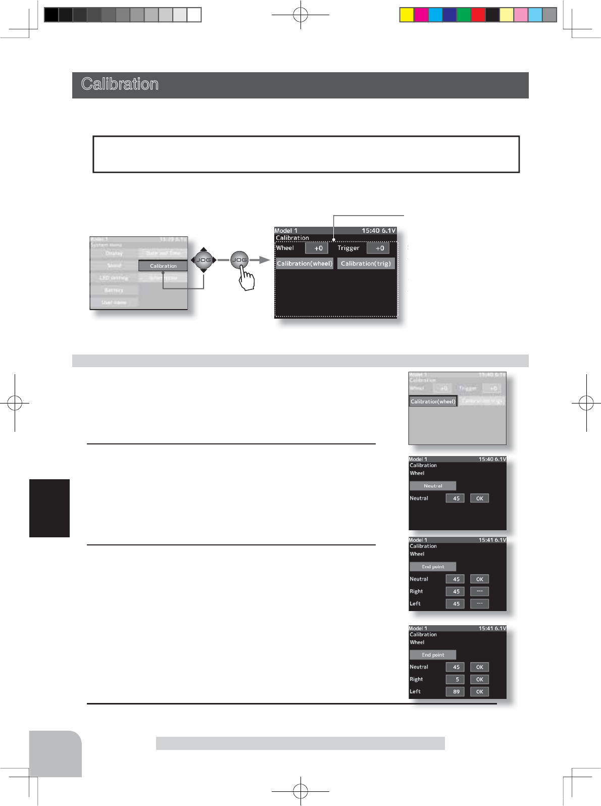
System menu
Setup item
Calibration(wheel)
Calibration(trigger)
Setup item selection
- Select by (JOG) button opera-
tion.
-Setup buttons
- Use the (JOG) buttons to
make setup.
152
Function
1(Steering neutral adjustment)
After pulling the wheel was lightly to the left or right, press
the (JOG) button in the state in which the wheel is not
touched. If neutral correction is OK, the end point correction
screen appears. If not within the correction range, the end
point correction screen will not appear.
Calibration
Steering and throttle correction can be applied. Use this function when a mechanical offset
has occurred for some reason.
(Preparation)
Select "Wheel" (steering side) by (JOG) button left or right
operation and press the (JOG) button. The neutral correction
screen appears.
Steering adjustment
2(Steering wheel travel adjustment)
In the end point correction screen (figure at the right) state,
lightly turn the wheel fully to the left and right and press the
(JOG) button. If end point correction is OK, the display re-
turns to the adjuster screen. If the end point is not within the
correction range, the display does not return to the adjuster
screen. In this case, return to the system menu screen by
pressing the (END) button. If operation cannot be ended nor-
mally even when correction is repeated, please contact the
Futaba Service Center.
3
When ending setting, return to the system menu screen by pressing the (END) button.
Calibration
However, if correction was applied, it may be necessary to recheck the set values of all
the setup functions.
Pres
s
This setting is displayed from the screen of the system menu. (p.144)
4PX-Eng-08-Function-104-156.indd 152 2014/07/18 17:36:23
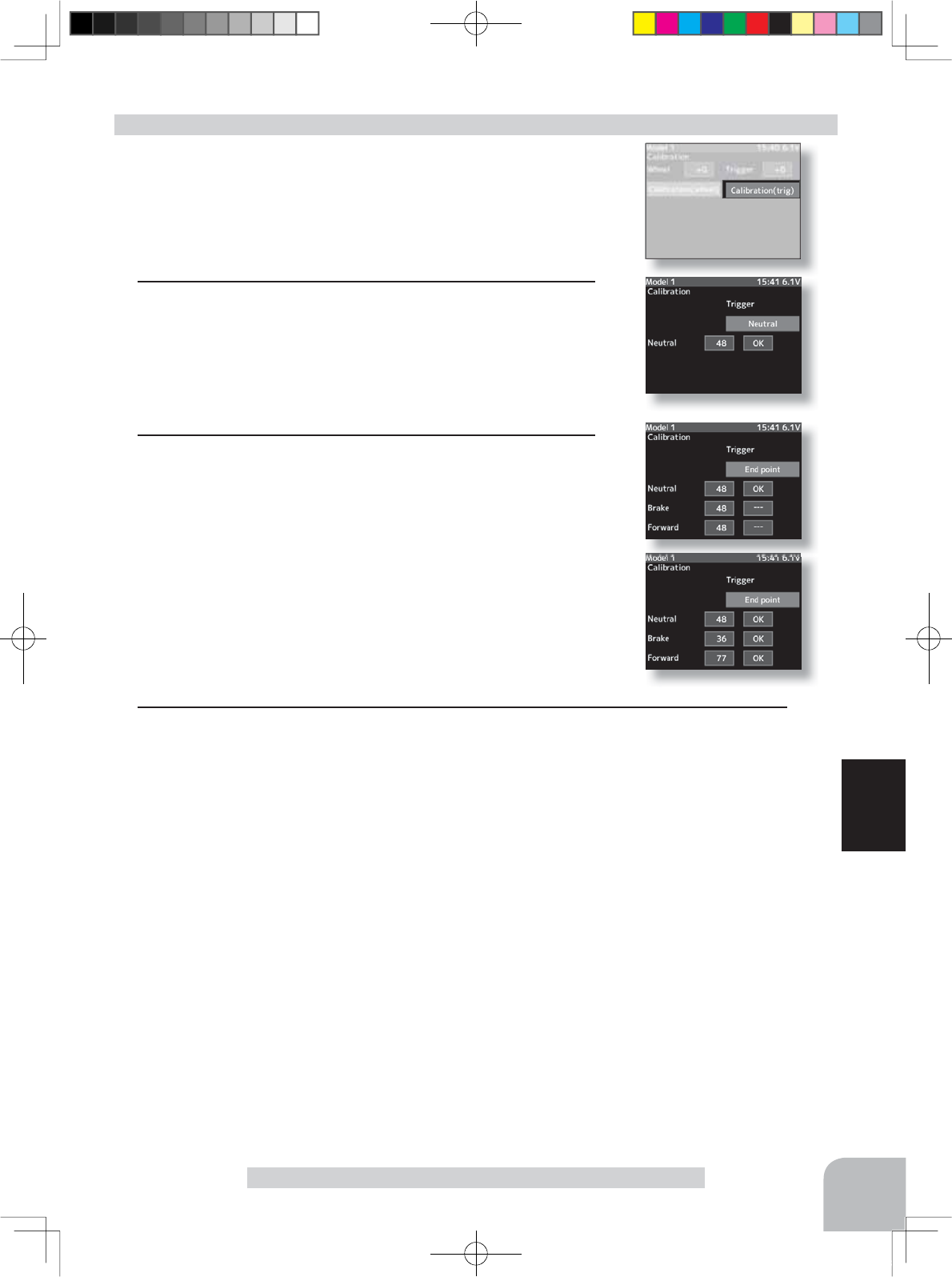
153
Function
Calibration
1(Throttle neutral adjustment)
After lightly pulling the throttle trigger to the left and right,
press the (JOG) button in the state in which the trigger is not
touched. If neutral correction is OK, the end point correction
screen appears. If not within the correction range, the end
point correction screen will not appear.
Throttle adjustment
(Preparation)
Select "Trigger" (throttle side) by (JOG) button left or right
operation and press the (JOG) button. The neutral correction
screen appears.
2(Steering travel adjustment)
In the end point correction screen (figure at the right) state,
lightly operate the trigger to the full forward and full brake
side and press the (JOG) button. If end point correction is
OK, the display returns to the adjuster screen. If not within
the correction range, the display will not return to the adjuster
screen. In this case, return to the system menu by pressing
the (END) button. When operation cannot be ended normally
even when correction is repeated, and cannot be ended nor-
mally, contact the Futaba Service Center.
3
When ending setting, return to the system menu screen by pressing the (END) button.
4PX-Eng-08-Function-104-156.indd 153 2014/07/18 17:36:23
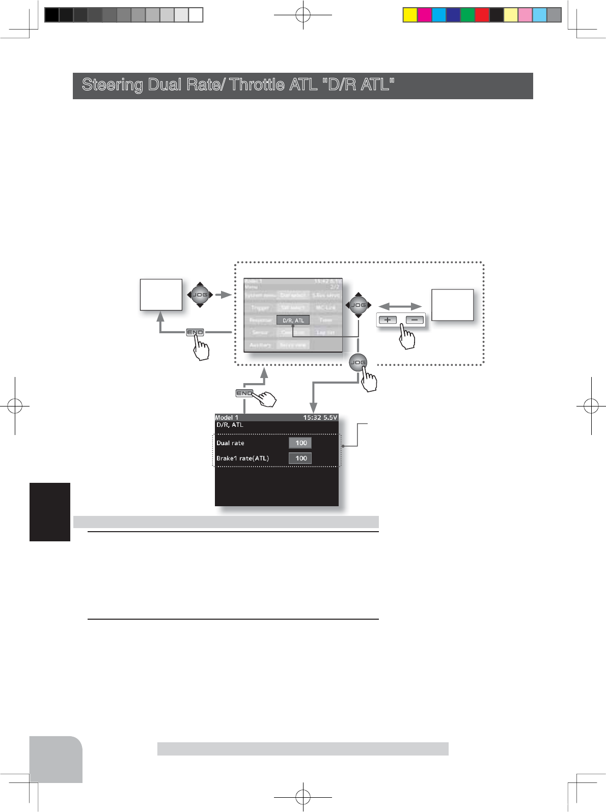
HOME
screen MENU 1
screen
or
MENU 2 screen
154
Function
Steering Dual Rate/ Throttle ATL "D/R ATL"
Steering Dual Rate/ Throttle ATL "D/R ATL"
D/R (Steering dual rate)
The steering left and right servo travels are adjusted simultaneously. This setting is linked
to transmitter grip dial DT5. When DT5 is assigned another function, dual
rate can be adjusted with this screen.
ATL (Brake1 rate)
This function decreases the set value when the braking effect is strong and increases the set
value when the braking effect is weak. This function is linked to transmitter
grip dial DT6. When DT6 is assigned another function, this function can be set with this
screen.
1
(Dual rate adjustment)
Select the setting item
"Dual
rete
"
or "Brake1 rate" by (JOG)
button up or down operation. Adjust the servo travel with the (+)
and (-) buttons.
This dual rate servo travel is linked to the grip trim.
2
When ending setting, return to the menu screen by pressing
the (END) button.
Dual rate adjustment
Setup item selection
- Select by (JOG) button up or
down operation.
Adjustment buttons
- Use the (+) and (-) buttons to
make adjustments.
- Press the (+) and (-) buttons
simultaneously (approx. 1 sec)
to return to the initial screen.
D/R rate (RATE)
0~100%
Initial value: 100
Setup Item
Dual rate
Brake1 rate (ATL)
Pres
s
Pres
s
Pres
s
Pre
Pres
s
4PX-Eng-08-Function-104-156.indd 154 2014/07/18 17:36:24
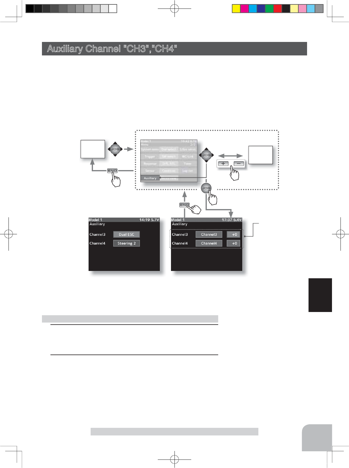
HOME
screen MENU 1
screen
or
MENU 2 screen
When mixing set at auxiliary channel
155
Function
Auxiliary Channel "CH3","CH4"
Auxiliary Channel "CH3","CH4"
The channel 3/4 servo position can be set from the transmitter. When CH3 is assigned to a
dial by the dial function (p.101), this setting is linked to that dial.
When CH3/4 is not assigned to a dial, it can be set with this screen.
When CH3/4 is assigned to a switch by the switch function (p.99), you cannot adjust the
CH3/4 via the screen.
:KHQ&+RU&+LVDVVLJQHGE\PL[LQJIXQFWLRQFKDQQHORSHUDWLRQFDQQRWEHSHUIRUPHG
at this screen.
Setup Item
Channel 3 position
Channel 4 position
Channel 3: Dual ESC mixing
Channel 4: Steering mixing
1(Position adjustment)
Use the (+) and (-) buttons to adjust the channel 3 or chan-
nel 4 position.
2When ending setting, return to the initial screen by pressing
the (END) button twice (for function menu screen, press the
(END) button once).
Channel 3/4 adjustment
Adjustment buttons
- Use the (+) and (-) buttons to
make adjustments.
- Press the (+) and (-) buttons
simultaneously (approx. 1 sec)
to return to the initial screen
Channel 3 position (POSI)
Channel 4 position (POSI)
0~100%
Initial value: 100%
Pres
s
Pres
s
Pres
s
Pre
Pres
s
4PX-Eng-08-Function-104-156.indd 155 2014/07/18 17:36:24
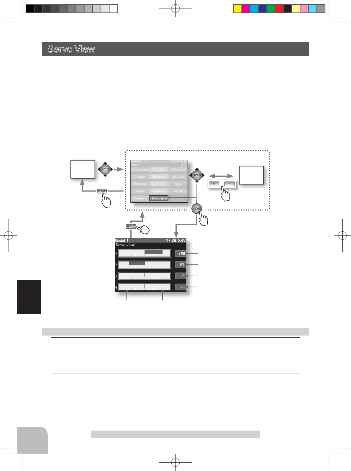
HOME
screen MENU 1
screen
or
MENU 2 screen
Pres
s
Pres
s
Pres
s
Pre
Pres
s
156
Function
Servo view
100% position100% position
1When ending servo operation checks,
return to the menu screen by pressing the (END) but-
ton.
2
When ending setting, return to the menu screen by pressing the (END) button.
Ending the "Servo view" screen
Steering operation
Throttle operation
Channel 3 operation
Servo View
Servo operation of each channel can be checked. Operation of the steering angle adjust-
PHQWZKHQDPL[LQJIXQFWLRQZDVVHWHWFFDQEHHDVLO\FKHFNHG
7KHQHXWUDOSRVLWLRQRIWKHWKURWWOHFKDQQHOYDULHVGHSHQGLQJRQWKHPRGHVGH¿QHGE\WKH
7ULJJHU5DWLR7KHVFUHHQVKRZQEHORZVKRZVDQH[DPSOHRI)RUZDUG%UDNHPRGH
Channel 4 operation
4PX-Eng-08-Function-104-156.indd 156 2014/07/18 17:36:24
157
Reference
Caution
Reference
Specifications
Transmitter T4PX
(Wheel system, 4 channels)
- Transmitting frequencies 2.4GHz band
- Futaba T-FHSS(
R304SB/SB-E
)/S-FHSS(R2104GF, R204GF-E/FASST-C2(
R614FS/
FF-E/FF, R604FS/FS-E
)
- Power requirement
(Ni-MH battery) NT5F1700B Ni-MH battery (6V)
(LiFe battery) FT2F1700BV2 (6.6V)
- Current drain 300mA or less (When the T-FHSS, Vibration off, back lighting on)
7UDQVPLWWLQJDQQWHQQDȜGLSROH
Receiver R304SB / R304SB-E: (T-FHSS system, 4 channels)
Receiving frequency: 2.4GHz band
Power requirement: 4.8V~7.4V battery / 3.5 ~ 8.4V useable (Dry cell battery cannot be used.)
System: T-FHSS system (auto detection)
Size:
R304SB :1.38x0.91x0.33"[[PPH[FOXGLQJDSURMHFWLRQSDUW
R304SB-E :1.38x0.91x0.49”[[PPH[FOXGLQJDSURMHFWLRQSDUW
Weight: R304SB :0.23oz. (6.6g) / R304SB-E :0.24oz. (6.7g)
6SHFL¿FDWLRQVDQGUDWLQJVDUHVXEMHFWWRFKDQJHZLWKRXWSULRUQRWLFH
When using the 4PX in the "Digital servo" type, always use it under the following conditions:
Servos :Futaba digital servo (including BLS Series brushless servos)
Receiver’s battery :Matched to the ratings of the receiver and connected digital servo (dry cell battery cannot be used).
Transmitter mode :Digital servo type(See p.39 for setting method.
)
Under other conditions, the set will not operate, or the specified performance will not be displayed even if it operates. In ad-
dition, it may cause servo trouble. Futaba will not be responsible for damage, etc. caused by combination with the products
of other companies.
In addition, the FSU Fail Safe Unit cannot be used because the system is different. Use the fail safe function of the trans-
mitter.
When using analog servos, always switch the 4PX servo type to the "Analog servo" mode.
Transmitter mode :
Analog servo type(See p.39 for setting method.)
Receiver’s battery :
Matched to the ratings of the receiver and connected servo.
The set cannot operate in the "Digital servo" type. Operation in this type will cause trouble with the servo and other equipment.
Digital servos (including BLS Series brushless servos) can also be used in the
"
Analog servo
"
type.
4PX-Eng-09-Reference-157-163.indd 157 2014/07/18 16:07:21
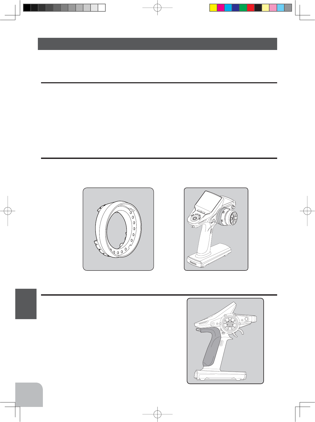
Example of installing angle spacer
Angle spacer
158
Reference
Large grip (for transmitter)
7KLVKDQGOHJULSLVODUJHUWKDQWKHVWDQGDUGKDQGOHJULS
,WLVSHUIHFWIRUWKRVHZLWKODUJHKDQGV
5HPRYHDQGUHSODFHWKHVWDQGDUGKDQGOHJULS
Optional Parts
7KHIROORZLQJSDUWVDUHDYDLODEOHDV73;RSWLRQV3XUFKDVHWKHPWRPDWFK\RXUDSSOLFD-
WLRQ)RURWKHURSWLRQDOSDUWVUHIHUWRRXUFDWDORJ
Transmitter Battery
:KHQSXUFKDVLQJDWUDQVPLWWHUEDWWHU\XVHWKHIROORZLQJ
Part name
HT5F1800B (6V/1800mAh) Ni-MH battery
FT2F1700B(6.6V/1700mAh)/2100BV2 (6.6V/2100mAh) Li-Fe battery
Please do not use the transmitter batteries HT5F1800B and
FT2F1700/2100BV2
as the receiv-
er's battery.
T4PX Angle spacer
7KLV$QJOHVSDFHULVRSWLRQSDUWIRU73;$QJOHRIDVWHHULQJZKHHOFDQEHFKDQJHG
5HIHUWRWKHSDJHRIWKLVPDQXDOIRUPHDQVRIDWWDFKPHQW
4PX-Eng-09-Reference-157-163.indd 158 2014/07/18 16:07:21
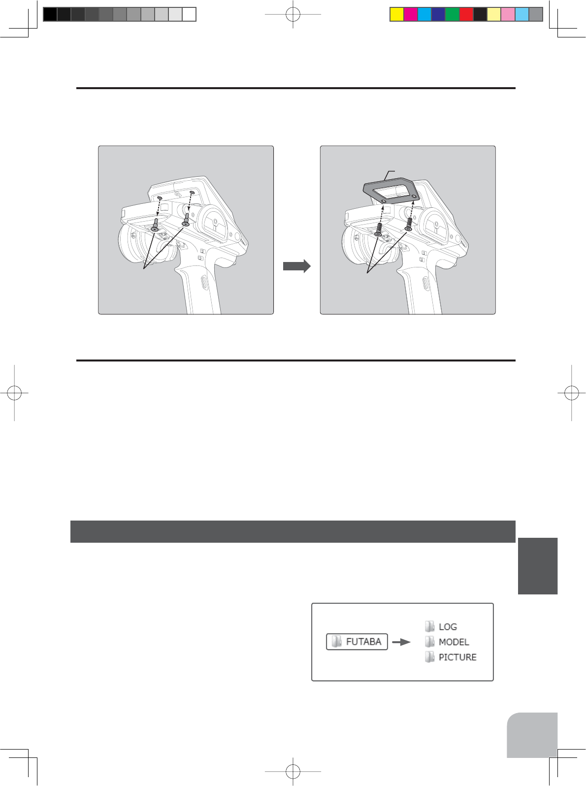
The flat head screws
(3x10)
Carbon handle
Rubber Bush
Using a 2.0 mm hex wrench
Rubber Bush is removed.
159
Reference
:KHQDPLFUR6'FDUGLVLQVWDOOHGLQWKH73;WUDQVPLWWHUDIROGHUFDOOHG"Futaba" is cre-
ated. Folders called "LOG" and "MODEL" are created in this folder. The "MODEL" folder
stores the model data and the "LOG" folder stores the telemetry log data. When "Screen
FDSWXUH" LV VHW DW WKH SXVK VZLWFK E\ VZLWFK
VHWWLQJDQLPDJHRIWKHVFUHHQWR EH GLVSOD\HG
RQWKH73;LVVDYHGE\WKDWVZLWFK7KHVDYHG
image is stored in a folder call "PICTURE". A
"PICTURE" folder is not created until "Screen
FDSWXUH" is set.
Carbon handle (for transmitter)
$QRSWLRQDOFDUERQKDQGOHFDQEHLQVWDOOHGWRWKH73;8VHWKHKH[ZUHQFKVXSSOLHG
ZLWKWKH3;VHWWRLQVWDOOLW7KHÀDWKHDGVFUHZV[DUHVXSSOLHGZLWKWKHRSWLRQDOFDU-
bon handle.
Telemetry sensors
8VDEOHVHQVRURSWLRQV$VRI-XQH
7HPSHUDWXUHVHQVRU6%673HUIHFWIRUHQJLQHKHDGHWF
7HPSHUDWXUHVHQVRU6%67(8VHGE\DWWDFKLQJWRDPRWRUHWF
5306HQVRU6%6500HDVXUHVVSHHGRYHUWKHWRUSPUDQJH
9ROWDJH6HQVRU6%690HDVXUHVH[WHUQDOSRZHUVXSSO\YROWDJHVXSWR9
About data saved to microSD card
4PX-Eng-09-Reference-157-163.indd 159 2014/07/18 16:07:22
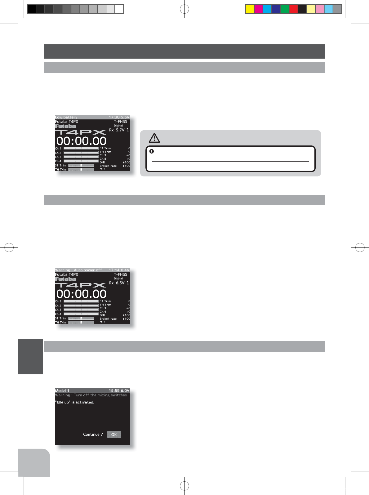
160
Reference
- If the alarm is not reset, the auto power off function will auto-
matically turn off the power after 5 minutes.
- The alarm stops even if the (JOG) button is pressed.
However, check the function switch.
Audible alarm:
Tone sounds (7 times) and stops (repeated)
Warning Displays
Low Battery Alarm
Power off forgotten alarm
,IWKHWUDQVPLWWHUEDWWHU\YROWDJHGURSVEHORZWKHXVDEOHUDQJHDQDXGLEOHDODUPZLOOVRXQG
DQG/RZEDWWHU\ZLOOEHGLVSOD\HG6LQFHWKHXVDEOHUDQJHRI/L)HDQG1L0+EDWWHULHVDQG
/L)HEDWWHULHVLVGLIIHUHQWWKHSRZHUVXSSO\XVHGPXVWEHVHWE\V\VWHPVHWWLQJS
$W 73; LQLWLDOL]DWLRQ LI VWHHULQJ ZKHHO WKURWWOH WULJJHU SXVKVZLWFKHGLWEXWWRQRURWKHU
RSHUDWLRQLVQRWSHUIRUPHGZLWKLQPLQXWHVDQDXGLEOHDODUPZLOOVRXQGDQGWKHPHVVDJH
:DUQLQJ$XWRSRZHURIIZLOODSSHDU,IVWHHULQJZKHHOWKURWWOH WULJJHU SXVK VZLWFK HGLW
EXWWRQRURWKHURSHUDWLRQLVSHUIRUPHGWKHDODUPLVUHVHW $OVRWXUQRIIWKHSRZHUZKHQWKH
WUDQVPLWWHULVQRWLQXVH,I\RXGRQRWZDQWWRXVHWKLVDODUPDQGWKHDXWRSRZHURIIIXQFWLRQ
WKH\FDQEHGLVDEOHGE\V\VWHPVHWWLQJS
Audible alarm: Continuous tone.
The vibrator: Active (initial setting) page 148
Warning
When a low battery alarm is generated, cease operation im-
mediately and retrieve the model.
If the battery goes dead while in operation, you will lose control.
MIX Warning
:KHQWKHSRZHUVZLWFKLVWXUQHGRQZKLOHWKHLGOHXSHQJLQHFXWRUQHXWUDOEUDNHIXQFWLRQ
VZLWFKLVRQDQDXGLEOHDODUPZLOOVRXQGDQG:DUQLQJZLOOEHGLVSOD\HGRQWKH/&':KHQ
WKDWIXQFWLRQVZLWFKLVWXUQHGRIIWKHDODUPZLOOVWRS
Audible alarm:
Tone sounds (7 times) and stops (repeated)
4PX-Eng-09-Reference-157-163.indd 160 2014/07/18 16:07:22
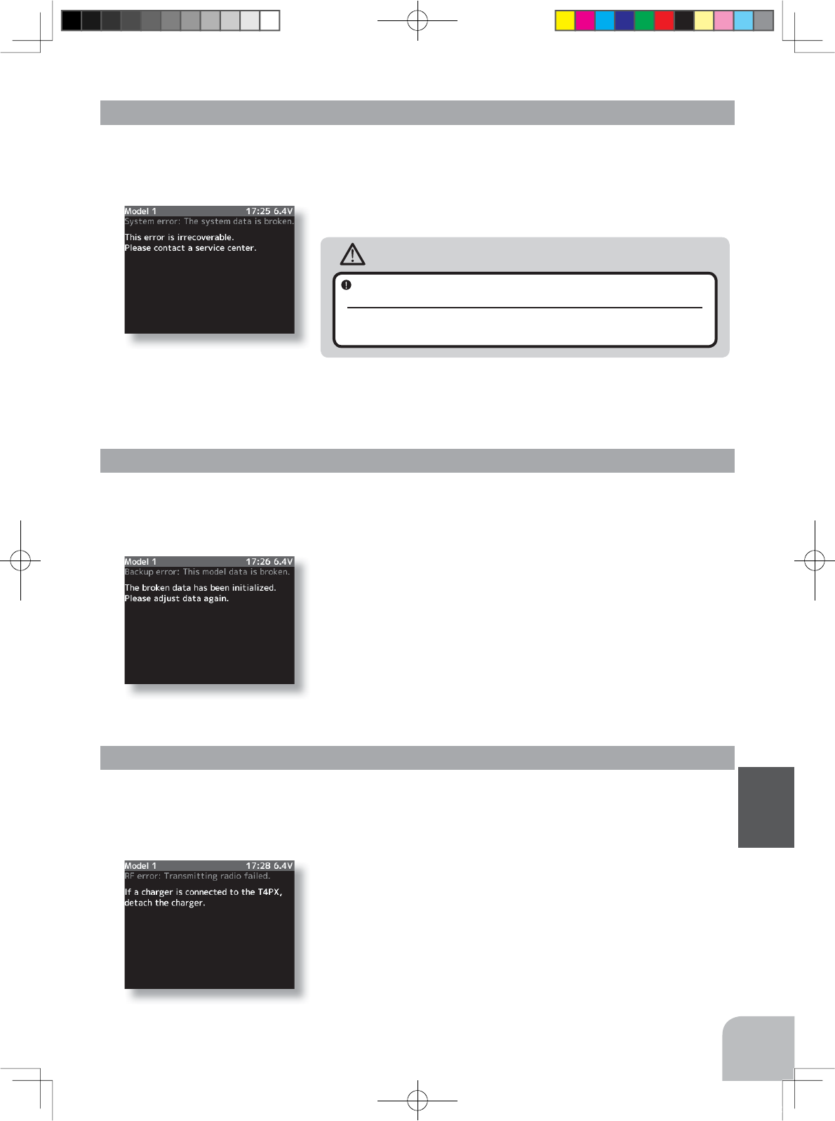
161
Reference
- To stop the alarm, turn off the power.
- Turn the power back on. If the alarm is not generated
again, there is no problem.
- To stop the alarm, turn off the power.
- Turn the power back on. If the alarm is generated again,
request repair from the Futaba Service Center.
Backup Error
RF Error
System Error
Audible alarm:
Tone sounds (7 times) and stops (repeated)
Audible alarm:
Tone sounds (7 times) and stops (repeated)
Audible alarm: Continuous tone.
The vibrator: Active (initial setting) page 148
Warning
When a system error is generated, immediately stop using
the system and request repair from the Futaba Service Center.
If you continue to use the system, the transmitter may malfunction and cause
loss of control.
,IWKHGDWDLQWKHWUDQVPLWWHULVQRWWUDQVIHUUHGQRUPDOO\ZKHQWKHSRZHULVWXUQHGRQDQDX-
GLEOHDODUPZLOOVRXQGDQG%DFNXSHUURUZLOOEHGLVSOD\HGRQWKH/&'
:KHQWKH5)PRGXOHGRHVQRWRSHUDWH"RF Error"LVGLVSOD\HGRQWKH/&'
,IWKHSRZHULVWXUQHGRQGXULQJFKDUJLQJDQ5)HUURUZLOOEHGLVSOD\HG DQG DQ DXGLEOH
DODUPZLOOVRXQG,PPHGLDWHO\WXUQRIIWKHSRZHU
If the data is lost for an unknown reason, an audible alarm will sound and "System error"
ZLOOEHGLVSOD\HGRQWKH/&'VFUHHQ
4PX-Eng-09-Reference-157-163.indd 161 2014/07/18 16:07:22

162
Reference
When requesting repair
%HIRUHUHTXHVWLQJ UHSDLU UHDG WKLVLQVWUXFWLRQDJDLQ DQG UHFKHFN\RXU V\VWHP 6KRXOGWKH
SUREOHPVFRQWLQXHUHTXHVWDVIROORZV
(Information needed for repair)
'HVFULEHWKHSUREOHPLQDVPXFKGHWDLODVSRVVLEOHDQGVHQGWKHOHWWHUDORQJZLWKWKHV\VWHP
in question.
6\PSWRP,QFOXGLQJWKHFRQGLWLRQVDQGZKHQWKHSUREOHPRFFXUUHG
- R/C System (Send transmitter, receiver and servos)
0RGHO7\SHRIPRGHOEUDQGQDPHDQGPRGHOQXPEHURUNLWQDPH
'HWDLOHGSDFNLQJOLVW0DNHDOLVWRIDOOLWHPVVHQWLQIRUUHSDLU
<RXUQDPHDGGUHVVDQGWHOHSKRQHQXPEHU
(Warranty)
Read the Warranty card.
:KHQUHTXHVWLQJZDUUDQW\VHUYLFHVHQGWKHFDUGRUVRPHW\SHRIGDWHGSURRISXUFKDVH
4PX-Eng-09-Reference-157-163.indd 162 2014/07/18 16:07:22

163
Reference
Federal Communications Commission Interference Statement (for U.S.A.)
7KLVHTXLSPHQWKDVEHHQWHVWHGDQGIRXQGWRFRPSO\ZLWKWKHOLPLWVIRUD&ODVV%GLJLWDOGH-
YLFHSXUVXDQWWR3DUWRIWKH)&&5XOHV7KHVHOLPLWVDUHGHVLJQHGWRSURYLGHUHDVRQDEOH
SURWHFWLRQDJDLQVWKDUPIXOLQWHUIHUHQFHLQDUHVLGHQWLDOLQVWDOODWLRQ
7KLVHTXLSPHQWJHQHUDWHVXVHVDQGFDQUDGLDWHUDGLRIUHTXHQF\HQHUJ\DQGLIQRWLQVWDOOHG
and used in accordance with the instructions, may cause harmful interference to radio com-
PXQLFDWLRQV+RZHYHUWKHUHLVQRJXDUDQWHHWKDWLQWHUIHUHQFHZLOOQRWRFFXULQDSDUWLFXODU
LQVWDOODWLRQ,IWKLVHTXLSPHQWGRHVFDXVHKDUPIXOLQWHUIHUHQFHWRUDGLRRUWHOHYLVLRQUHFHS-
WLRQZKLFKFDQEHGHWHUPLQHGE\WXUQLQJWKHHTXLSPHQWRIIDQGRQWKHXVHULVHQFRXUDJHG
to try to correct the interference by one or more of the following measures:
--Reorient or relocate the receiving antenna.
,QFUHDVHWKHVHSDUDWLRQEHWZHHQWKHHTXLSPHQWDQGUHFHLYHU
&RQQHFWWKHHTXLSPHQWLQWRDQRXWOHWRQDFLUFXLWGLIIHUHQWIURPWKDWWRZKLFKWKHUHFHLYHU
is connected.
&RQVXOWWKHGHDOHURUDQH[SHULHQFHGUDGLR79WHFKQLFLDQIRUKHOS
Compliance Information Statement (for U.S.A.)
7KLVGHYLFHWUDGHQDPH)XWDED&RUSRUDWLRQPRGHOQXPEHUT4PXFRPSOLHVZLWK
SDUWRIWKH)&&5XOHV2SHUDWLRQLVVXEMHFWWRWKHIROORZLQJWZRFRQGLWLRQV
7KLVGHYLFHPD\QRWFDXVHKDUPIXOLQWHUIHUHQFHDQG7KLVGHYLFHPXVWDFFHSWDQ\LQ-
WHUIHUHQFHUHFHLYHGLQFOXGLQJLQWHUIHUHQFHWKDWPD\FDXVHXQGHVLUHGRSHUDWLRQ
7KLVPRGXOHPHHWVWKHUHTXLUHPHQWVIRUDPRELOHGHYLFHWKDWPD\EHXVHGDWVHSDUDWLRQ
GLVWDQFHVRIPRUHWKDQFPIURPKXPDQERG\7RPHHWWKH5)H[SRVXUHUHTXLUHPHQWVRI
the FCC this device shall not be co-located with another transmitting device.
7KHUHVSRQVLEOHSDUW\IRUWKHFRPSOLDQFHRIWKLVGHYLFHLV
Futaba Service Center
1$SROOR'ULYH6XLWH&KDPSDLJQ,/86$
7(/RU(PDLOVXSSRUW#IXWDEDUFFRP6XSSRUW
7(/RU(PDLOIXWDEDVHUYLFH#KREELFRFRP6HUYLFH
CAUTION:
7RDVVXUHFRQWLQXHG)&&FRPSOLDQFH
$Q\ FKDQJHV RU PRGL¿FDWLRQV QRW H[SUHVVO\ DSSURYHG E\ WKH JUDQWHH RI WKLV GHYLFH FRXOG
YRLGWKHXVHU¶VDXWKRULW\WRRSHUDWHWKHHTXLSPHQW
Exposure to Radio Frequency Radiation
7R FRPSO\ ZLWK )&& 5) H[SRVXUH FRPSOLDQFH UHTXLUHPHQWV D VHSDUDWLRQ GLVWDQFH RI DW
OHDVWFPPXVWEHPDLQWDLQHGEHWZHHQWKHDQWHQQDRIWKLVGHYLFHDQGDOOSHUVRQV7KLVGH-
YLFHPXVWQRWEHORFDWHGRURSHUDWLQJLQFRQMXQFWLRQZLWKDQ\RWKHUDQWHQQDRUWUDQVPLWWHU
©Copyright 2010. No part of this manual may be reproduced in any form without prior permission. The contents of this manual are subject to
change without prior notice. While this manual has been carefully written, there may be inadvertent errors or omissions. Please contact our
service center if you feel that any corrections or clarifications should be made.
FUTABA CORPORATION Phone: +81 475 32 6982, Facsimile: +81 475 32 6983
<DEXWVXND&KRVHLPXUD&KRVHLJXQ&KLED-DSDQ
1M23N29402 ©FUTABA CORPORATION 2014, 07 (1)
4PX-Eng-09-Reference-157-163.indd 163 2014/07/18 16:07:23