G4S Monitoring Technologies SOL915 OM247 SOLO2 User Manual User guide
G4S Monitoring Technologies Limited OM247 SOLO2 User guide
UserManual.wiki
>
G4S Monitoring Technologies
>
SOL915 User Manual
>
User guide
Contents
1.
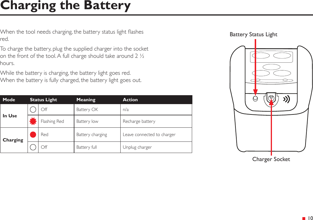
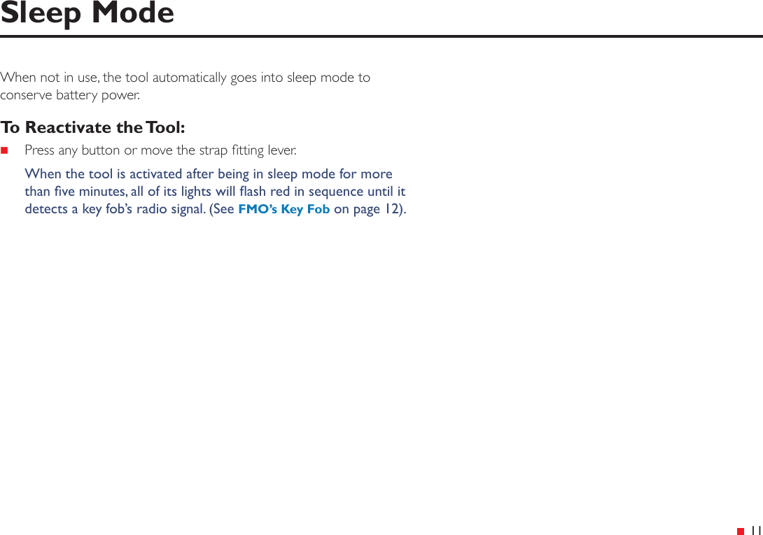
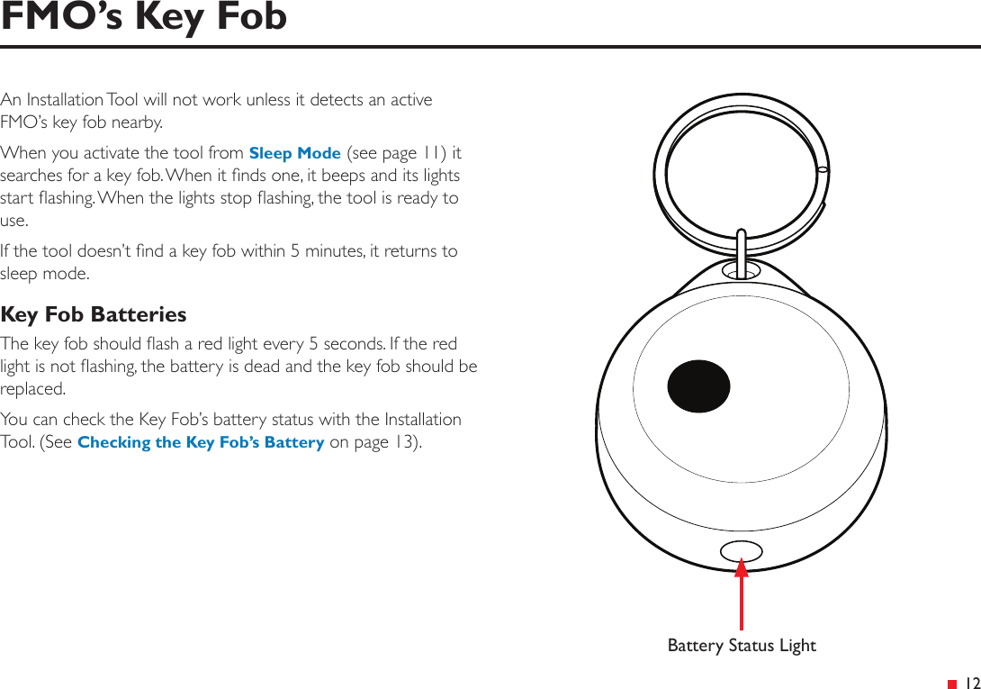
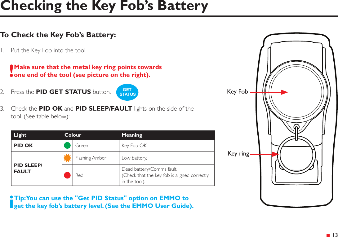
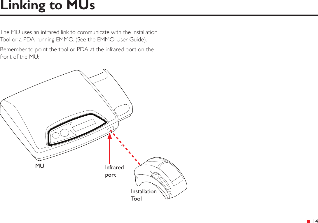
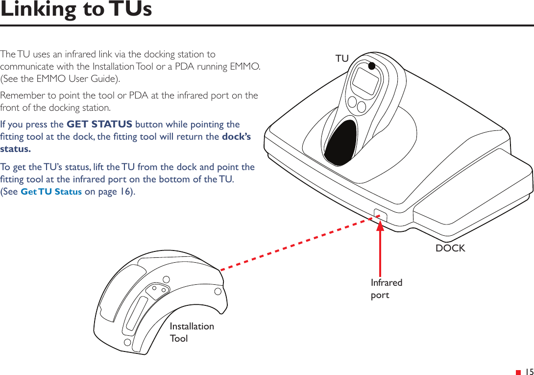
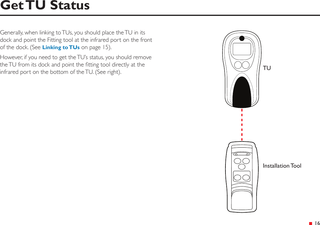
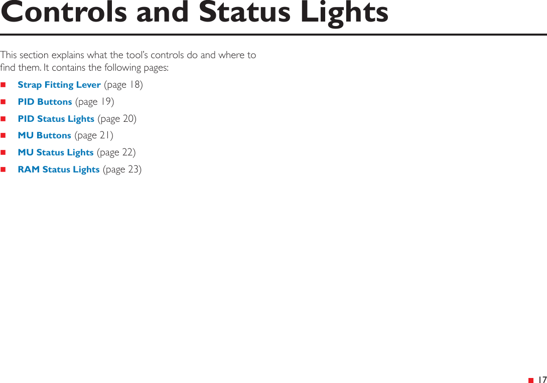
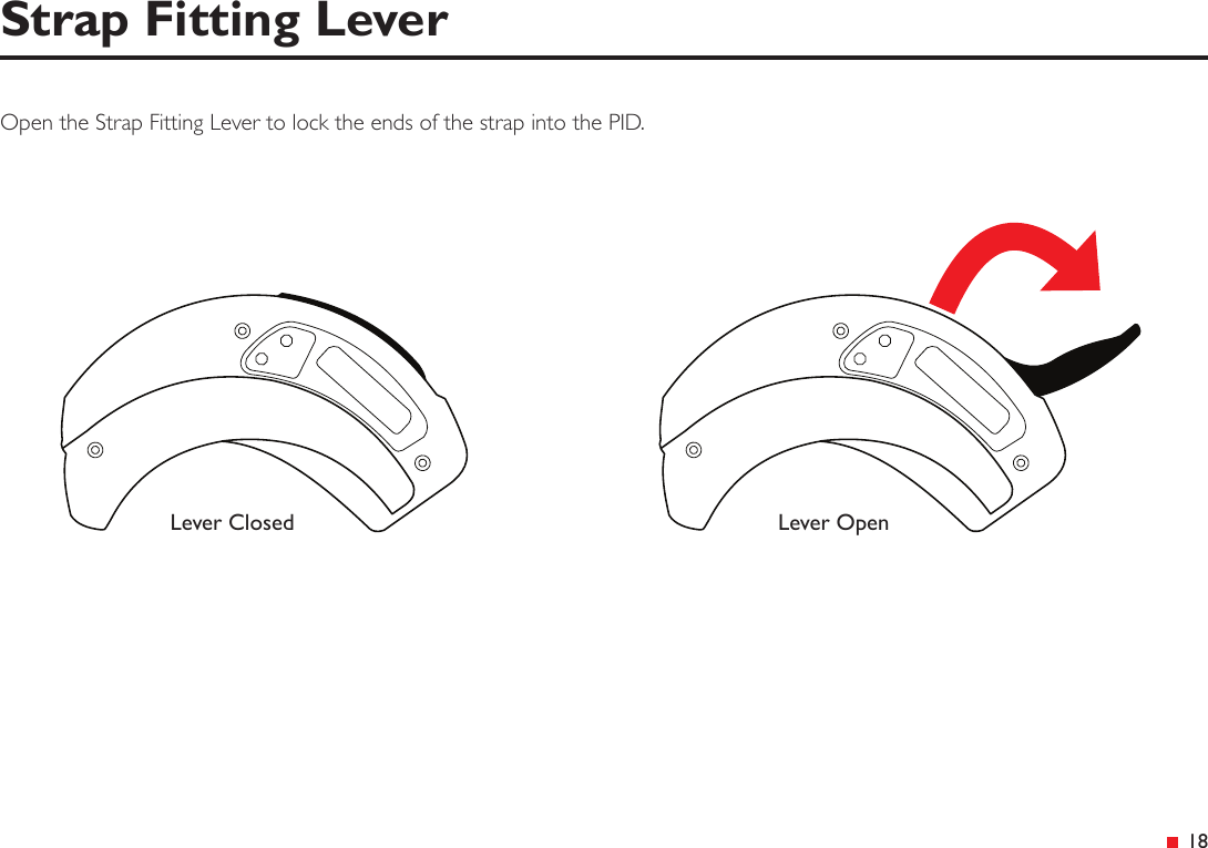
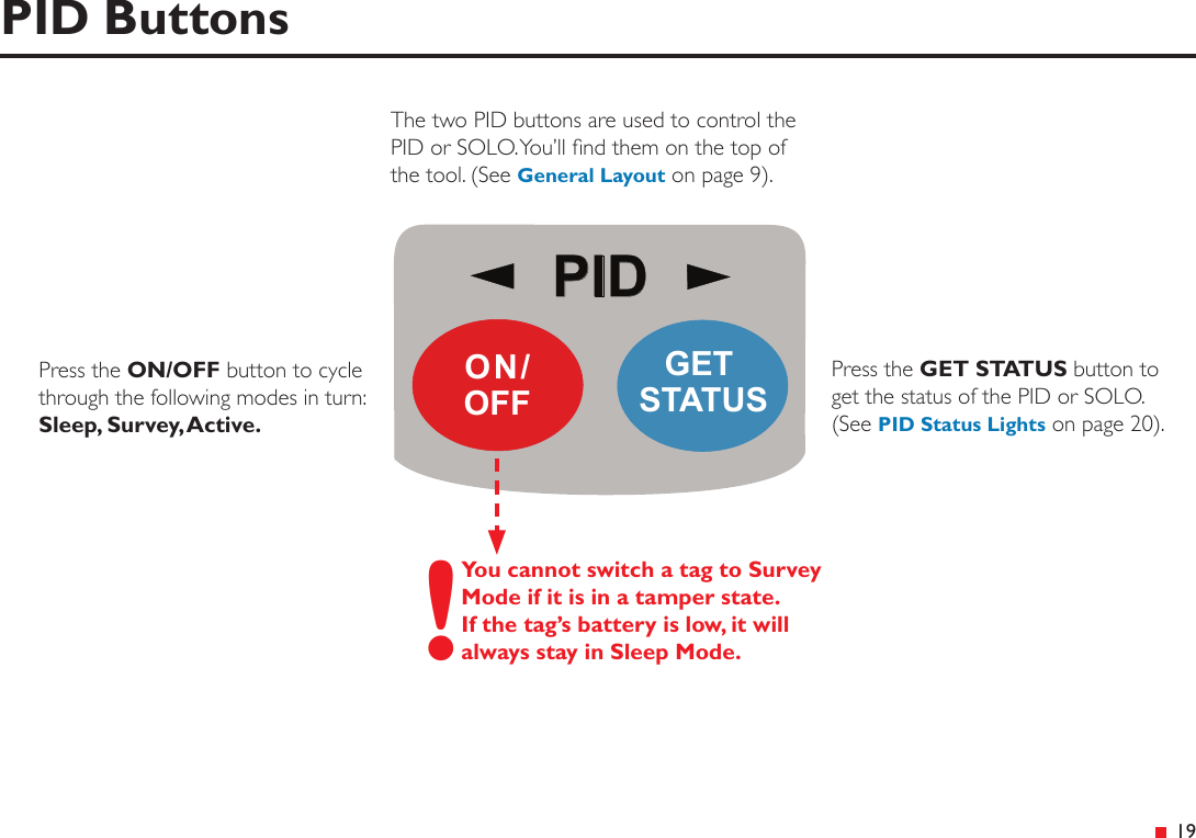
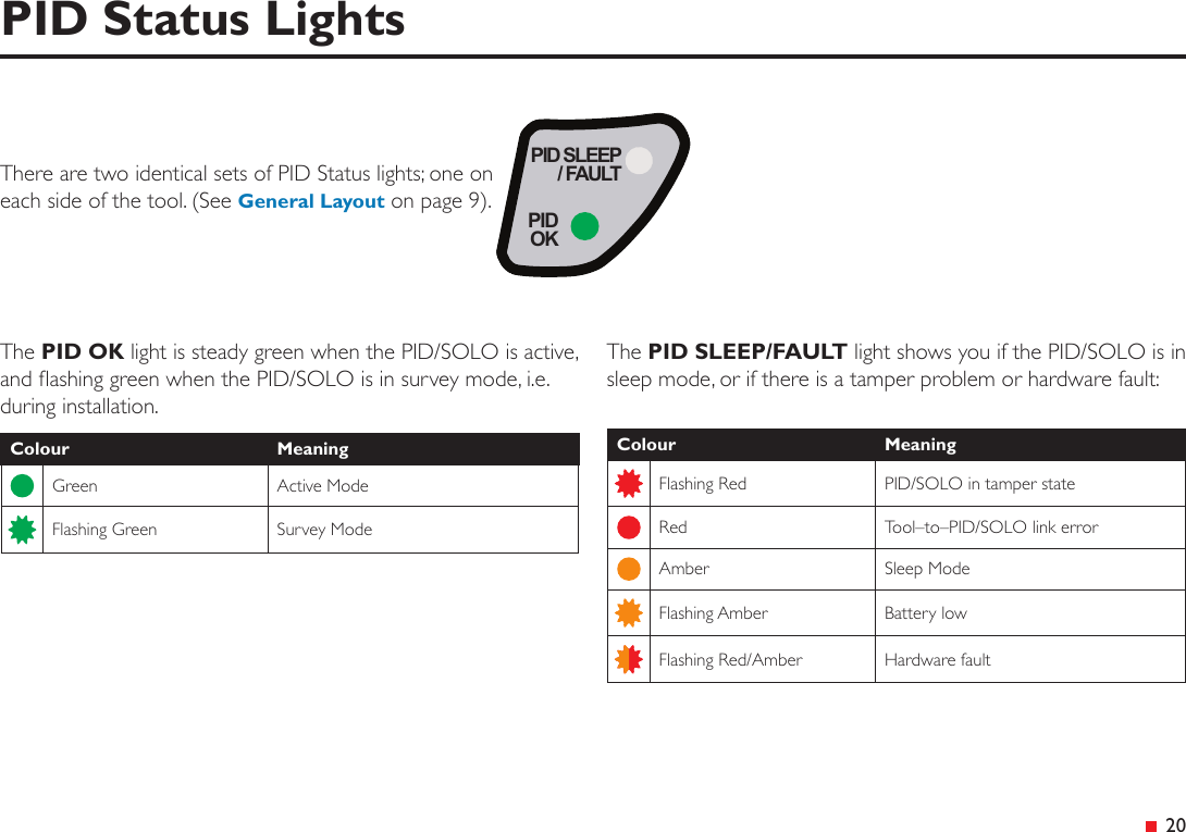
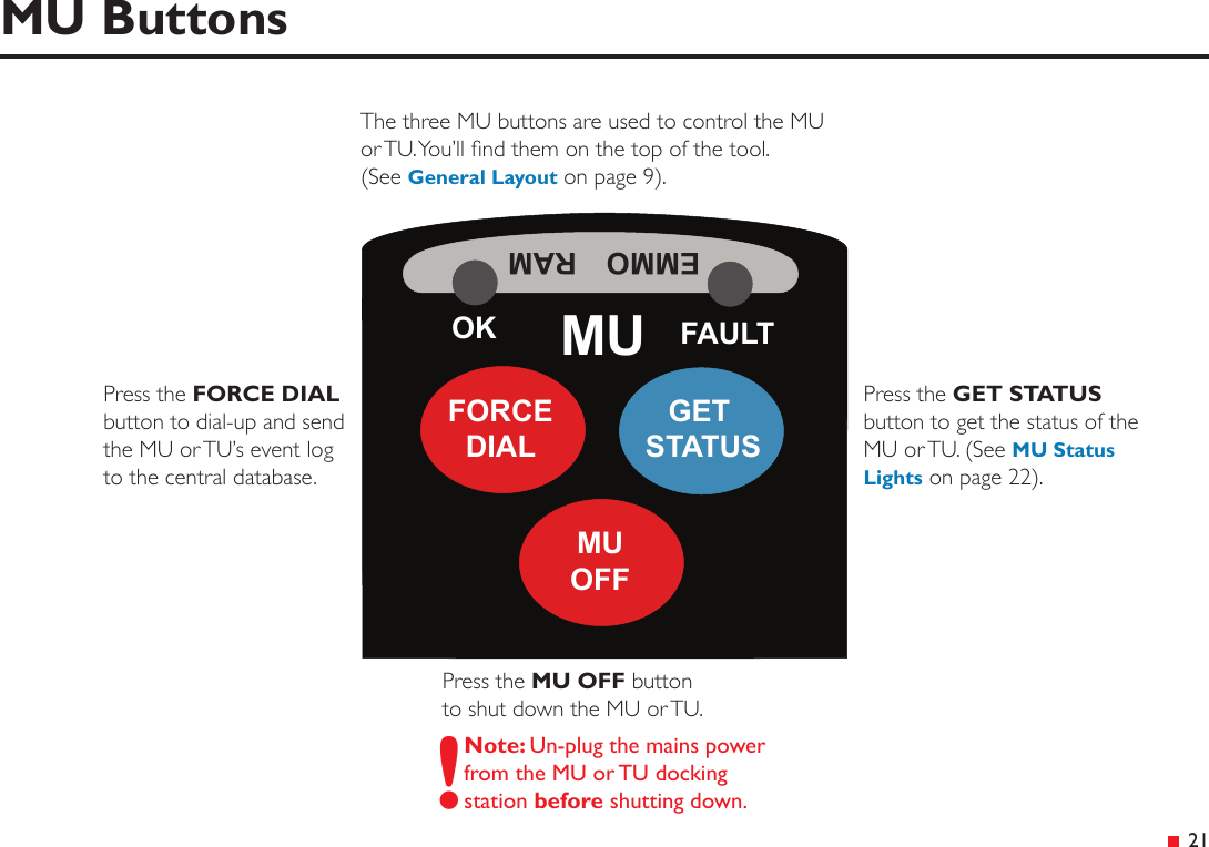
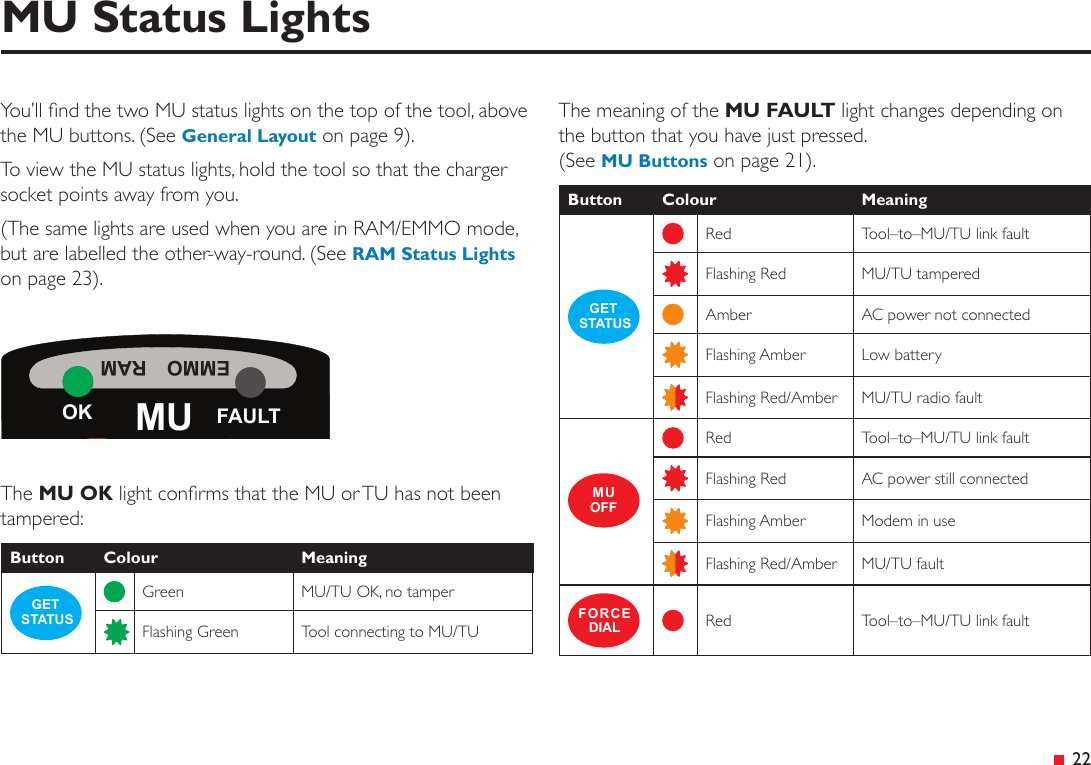
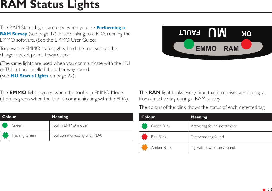
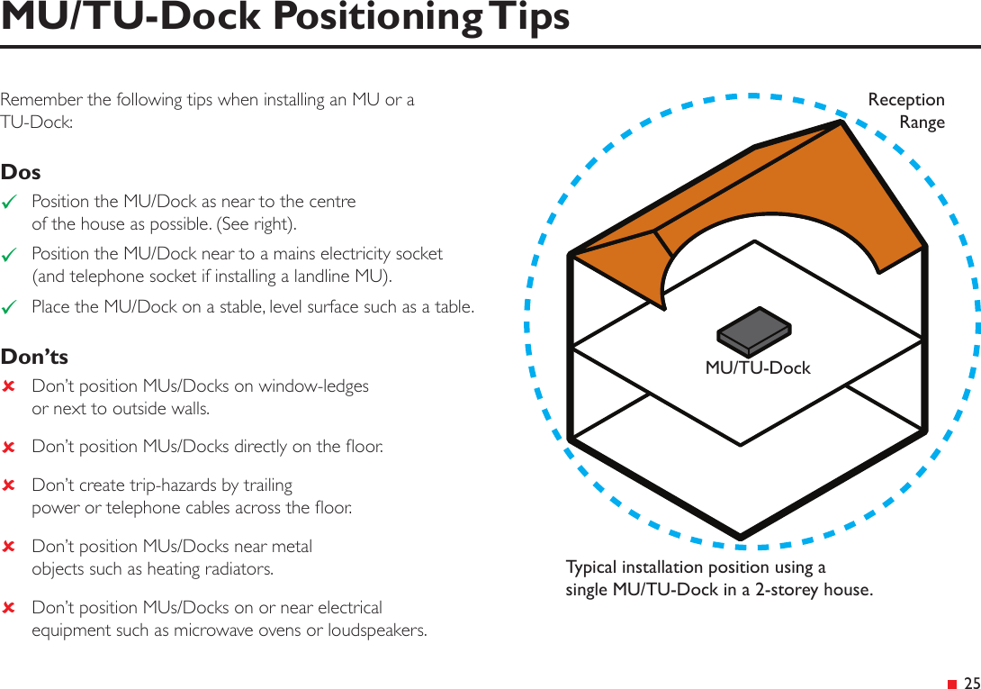
User guide
2.
User Guide (Safety)
3.
User Instructions
4.
User guide Solo
5.
User guide Solo (safety)
User guide
Navigation menu
Upload a User Manual
Namespaces
Wiki Guide
HTML
PDF
Info
Views
User Manual
Discussion / Help
Navigation