G4S Monitoring Technologies SOL915 OM247 SOLO2 User Manual User guide
G4S Monitoring Technologies Limited OM247 SOLO2 User guide
Contents
User guide

OM247
Installation Guide

2
OM247 Installation Tool User Guide
Issue Date: 07/09/11
Document No: 94-0033-4-F
G4S Monitoring Technologies Ltd
4 Dominus Way
Meridian Business Park
Leicester
LE19 1RP UK
Tel: +44 (0) 116 229 2600
Fax: +44 (0) 116 229 2604
Web: www.g4s.com/uk
Copyright © 2011 G4S Monitoring Technologies Ltd. All rights reserved.
Copyright in the whole and every part of this document belongs to G4S Monitoring Technologies Limited (the “Owner”) and may
not be used, sold, transferred, copied or reproduced in whole or in part in any manner or form or in or on any media to any person
other than in accordance with the terms of the Owner’s Agreement or otherwise without the prior written consent of the Owner.
All brand or product names are trademarks or registered trademarks of their respective companies or organisations.

3
Table of Contents
Introduction ..........................................................4
Welcome ....................................................................................................................................... 5
Terms and Abbreviations .................................................................................................... 6
Overview ......................................................................................................................................7
Getting Started ....................................................8
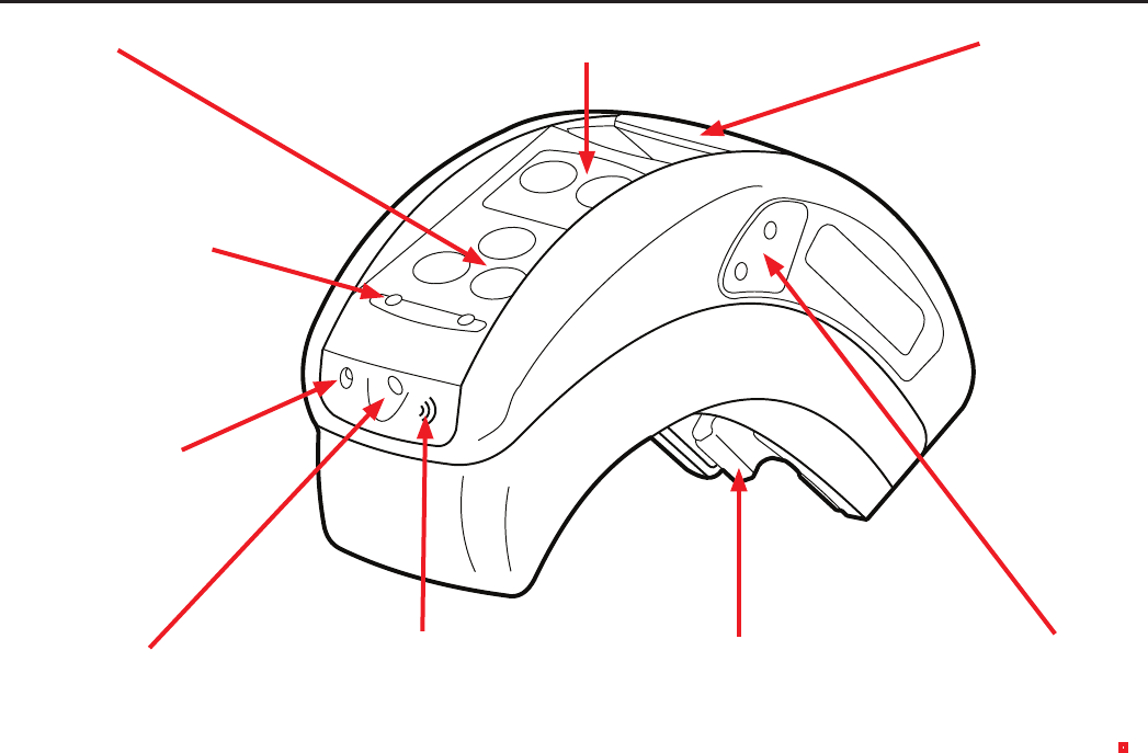
General Layout .......................................................................................................................... 9
Charging the Battery ............................................................................................................10
Sleep Mode ................................................................................................................................11
FMO’s Key Fob .........................................................................................................................12
Checking the Key Fob’s Battery .....................................................................................13
Linking to MUs .........................................................................................................................14
Linking to TUs ...........................................................................................................................15
Get TU Status ...........................................................................................................................16
Controls and Status Lights ............................... 17
Strap Fitting Lever ..................................................................................................................18
PID Buttons ................................................................................................................................19
PID Status Lights .....................................................................................................................20
MU Buttons ................................................................................................................................21
MU Status Lights .....................................................................................................................22
RAM Status Lights ..................................................................................................................23
Installing Monitoring Equipment ..................... 24
MU/TU-Dock Positioning Tips ........................................................................................25
Initialising an MU .....................................................................................................................26
Initialising a TU ..........................................................................................................................27
Getting a GPS Location Fix ..............................................................................................28
Preparing Straps for Installation ......................................................................................29
Fitting a PID to a Subject ...................................................................................................30
Fitting a SOLO to a Subject .............................................................................................33
MU Range Survey and Data Upload ...........................................................................37
TU Range Survey and Data Upload ............................................................................39
Removing and Replacing Tags .......................... 41
Abandoning an Install ...........................................................................................................42
Removing a Tag.........................................................................................................................43
Replacing a Tag..........................................................................................................................44
Tamper Investigation & RAM Survey .............. 45
Investigating Tamper Alerts ................................................................................................46
Performing a RAM Survey .................................................................................................47
Trouble Shooting ............................................... 48
Installation Tool Errors .........................................................................................................49
MU Error Messages ...............................................................................................................50
TU Error Messages ................................................................................................................52
Index ................................................................... 54


5
Welcome
Welcome to the Installation Tool User Guide. It has been written for Field
Monitoring Ofcers (FMOs) who need to install and check monitoring
equipment. It is arranged in the following sections:
Getting Started (page 8) explains the basics that you’ll need to
know before using the Installation Tool for the rst time.
Controls and Status Lights (page 17) shows you what the tool’s
buttons do, and explains what the different coloured lights mean.
Installing Monitoring Equipment (page 24) describes how to install
tags and monitoring / tracking devices.
Removing and Replacing Tags (page 41) describes how to
decommission and replace ‘PID’ and ‘SOLO’ tags.
Tamper Investigation & RAM Survey (page 45) describes how
to investigate suspected tag-tampers and how to perform a RAM
(Random Alternative Monitoring) survey.
Trouble Shooting (page 48) explains what the MU and TU error
messages mean, and how to resolve them.
Related Documents
EMMO User Guide

6
Terms and Abbreviations
This page explains the terms and abbreviations used in this guide:
Term Meaning
DOCK Docking Station—intelligent docking/charging station for the OM247-TRAK (TU).
EMMO Electronic Monitoring Mobile Organiser—a software program that runs on a PDA. It is used to display
the full status details of the monitoring equipment. (See the EMMO User Guide).
FMO Field Monitoring Ofcer—an Ofcer who visits the subject, typically at the curfew address, to install the
monitoring equipment, set up the curfew and investigate any problems during the curfew.
GPS Global Positioning System—the satellite system used to track the position of a TU or SOLO.
GPRS General Packet Radio Service—extension of the GSM standard, primarily used for data transfer
applications.
GSM Global System for Mobile communications—the international standard for mobile telephones.
IrDA Infrared Data Association—the standard protocol for infrared communications.
LBS Location Based Service—method of locating a TU or SOLO by calculating its distance from mobile-phone
masts. Used as a back-up to GPS location.
MU (OM247-MU) Monitoring Unit—the telephone unit that detects any nearby PIDs, and automatically contacts the Control
Centre if the curfew conditions are broken.
PDA Personal Digital Assistant—a small, hand-held portable computer.
PID (OM247-PID) Personal Identication Device—an electronic tag worn by a subject.
RAM Random Alternative Monitoring—the survey mode used to detect any nearby PIDs.
SOLO (OM247-SOLO) A one-piece GPS-enabled tag worn by a subject.
Subject A person who is being electronically monitored as a part of a curfew order.
Tag An electronic monitoring bracelet worn by the subject—either an OM247-PID or an OM247-SOLO.
TU (OM247-TRAK) Tracking Unit—A GPS-enabled device carried by a subject.

7
Overview
The OM247-FIT Fitting and Installation Tool is a multi-function
device. It combines a mechanical tting-tool with an electronic
control unit.
Using just a single tool, you can set up and t a tag to a subject
and install a monitoring or tracking unit. The tool can also be
used to investigate any suspected tampering with the monitoring
equipment. The same tool is used to un-install the monitoring
equipment at the end of the curfew period.
Every tool has a serial number printed on its side. This unique ID
is automatically recorded in the central database whenever the
tool is used to install any monitoring equipment.
In RAM (Random Alternative Monitoring) mode, the tool can
be used to detect any nearby tags. This allows you to perform
a ‘drive-by’ check to conrm that a subject is complying with
their curfew conditions. You can also connect the tool to a PDA
running ‘EMMO’ to display the full details of any tags that have
been detected. (See the EMMO User Guide).

8
This section explains the basics that you’ll need to know to use
the Installation Tool. It contains the following pages:
General Layout (page 9)
Charging the Battery (page 10)
Sleep Mode (page 11)
FMO’s Key Fob (page 12)
Checking the Key Fob’s Battery (page 13)
Linking to MUs (page 14)
Linking to TUs (page 15)
Getting Started
10
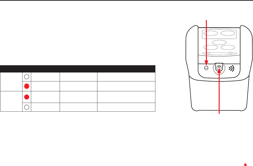
When the tool needs charging, the battery status light ashes
red.
To charge the battery, plug the supplied charger into the socket
on the front of the tool. A full charge should take around 2 ½
hours.
While the battery is charging, the battery light goes red.
When the battery is fully charged, the battery light goes out.
Charging the Battery
Mode Status Light Meaning Action
In Use
Off Battery OK n/a
Flashing Red Battery low Recharge battery
Charging
Red Battery charging Leave connected to charger
Off Battery full Unplug charger
Battery Status Light
Charger Socket

11
Sleep Mode
When not in use, the tool automatically goes into sleep mode to
conserve battery power.
To Reactivate the Tool:
Press any button or move the strap tting lever.
When the tool is activated after being in sleep mode for more
than ve minutes, all of its lights will ash red in sequence until it
detects a key fob’s radio signal. (See FMO’s Key Fob on page 12).
12
FMO’s Key Fob
An Installation Tool will not work unless it detects an active
FMO’s key fob nearby.
When you activate the tool from Sleep Mode (see page 11) it
searches for a key fob. When it nds one, it beeps and its lights
start ashing. When the lights stop ashing, the tool is ready to
use.
If the tool doesn’t nd a key fob within 5 minutes, it returns to
sleep mode.
Key Fob Batteries
The key fob should ash a red light every 5 seconds. If the red
light is not ashing, the battery is dead and the key fob should be
replaced.
You can check the Key Fob’s battery status with the Installation
Tool. (See Checking the Key Fob’s Battery on page 13).
Battery Status Light
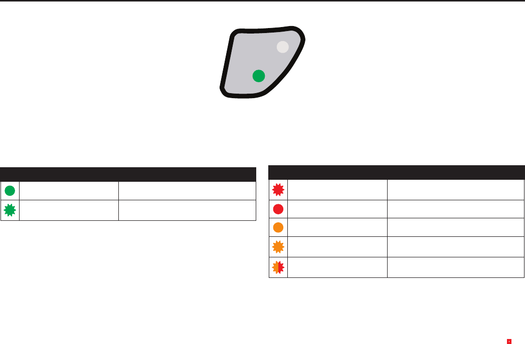
13
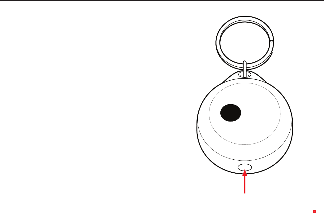
To Check the Key Fob’s Battery:
1. Put the Key Fob into the tool.
!Make sure that the metal key ring points towards
one end of the tool (see picture on the right).
2. Press the PID GET STATUS button.
3. Check the PID OK and PID SLEEP/FAULT lights on the side of the
tool. (See table below):
Light Colour Meaning
PID OK Green Key Fob OK.
PID SLEEP/
FAULT
Flashing Amber Low battery.
Red
Dead battery/Comms fault.
(Check that the key fob is aligned correctly
in the tool).
iTip: You can use the "Get PID Status" option on EMMO to
get the key fob’s battery level. (See the EMMO User Guide).
Checking the Key Fob’s Battery
GET
STATUS Key Fob
Key ring
14
Linking to MUs
Infrared
port
MU
Installation
Tool
The MU uses an infrared link to communicate with the Installation
Tool or a PDA running EMMO. (See the EMMO User Guide).
Remember to point the tool or PDA at the infrared port on the
front of the MU:
15
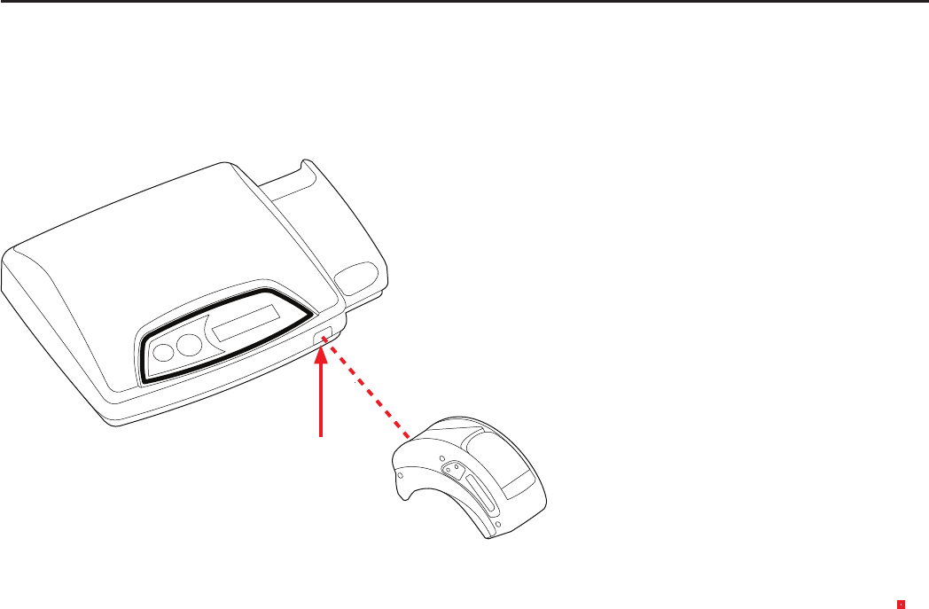
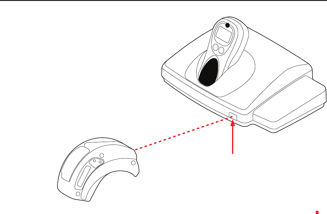
Linking to TUs
Infrared
port
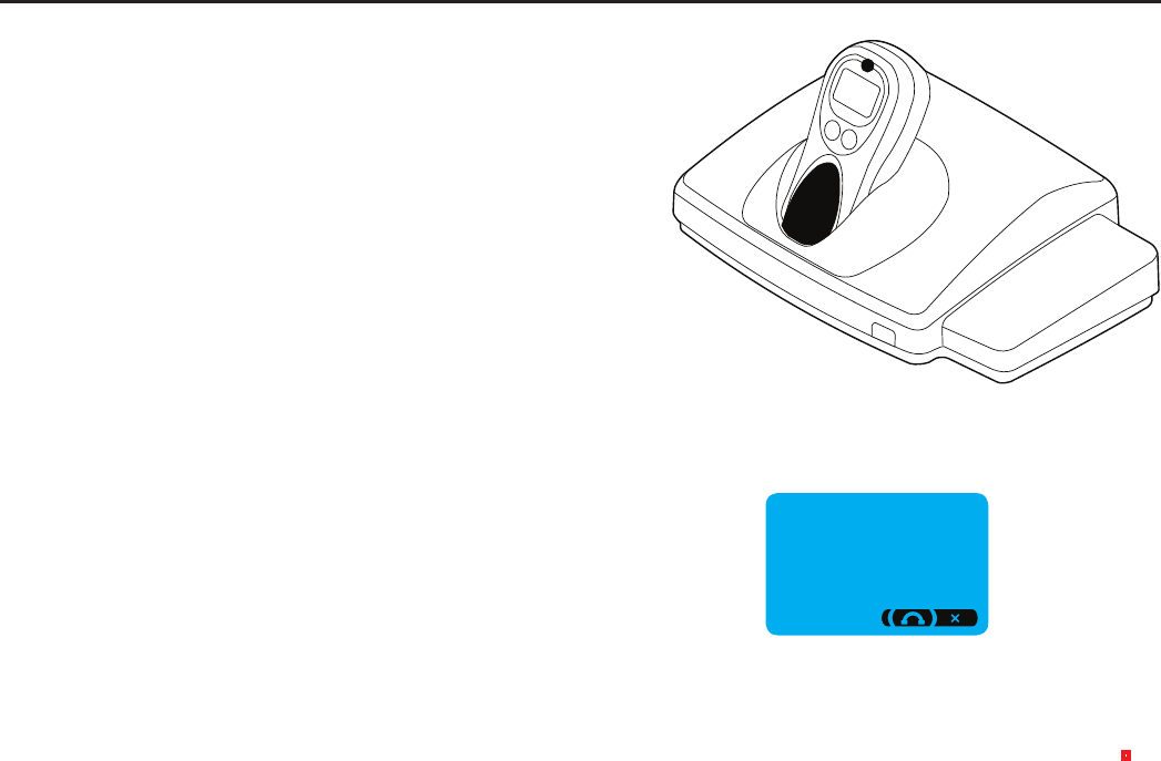
The TU uses an infrared link via the docking station to
communicate with the Installation Tool or a PDA running EMMO.
(See the EMMO User Guide).
Remember to point the tool or PDA at the infrared port on the
front of the docking station.
If you press the GET STATUS button while pointing the
tting tool at the dock, the tting tool will return the dock’s
status.
To get the TU’s status, lift the TU from the dock and point the
tting tool at the infrared port on the bottom of the TU.
(See Get TU Status on page 16).
TU
DOCK
Installation
Tool
16
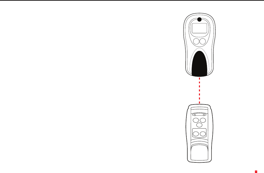
Get TU Status
Generally, when linking to TUs, you should place the TU in its
dock and point the Fitting tool at the infrared port on the front
of the dock. (See Linking to TUs on page 15).
However, if you need to get the TU’s status, you should remove
the TU from its dock and point the tting tool directly at the
infrared port on the bottom of the TU. (See right). TU
Installation Tool

18
Strap Fitting Lever
Lever Closed Lever Open
Open the Strap Fitting Lever to lock the ends of the strap into the PID.
PID
GET
STATUS
ON/
OFF
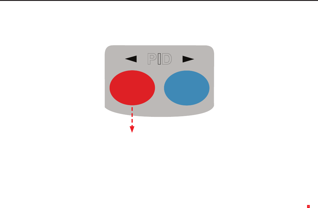
19
Press the ON/OFF button to cycle
through the following modes in turn:
Sleep, Survey, Active.
PID Buttons
The two PID buttons are used to control the
PID or SOLO. You’ll nd them on the top of
the tool. (See General Layout on page 9).
Press the GET STATUS button to
get the status of the PID or SOLO.
(See PID Status Lights on page 20).
!You cannot switch a tag to Survey
Mode if it is in a tamper state.
If the tag’s battery is low, it will
always stay in Sleep Mode.
PID SLEEP
/ FAULT
PID
OK
20
PID Status Lights
The PID OK light is steady green when the PID/SOLO is active,
and ashing green when the PID/SOLO is in survey mode, i.e.
during installation.
Colour Meaning
Green Active Mode
Flashing Green Survey Mode
The PID SLEEP/FAULT light shows you if the PID/SOLO is in
sleep mode, or if there is a tamper problem or hardware fault:
Colour Meaning
Flashing Red PID/SOLO in tamper state
Red Tool–to–PID/SOLO link error
Amber Sleep Mode
Flashing Amber Battery low
Flashing Red/Amber Hardware fault
There are two identical sets of PID Status lights; one on
each side of the tool. (See General Layout on page 9).

21
MU Buttons
Press the GET STATUS
button to get the status of the
MU or TU. (See MU Status
Lights on page 22).
GET
STATUS
FORCE
DIAL
MU
OFF
OK MU FAULT
EMMO RAM
The three MU buttons are used to control the MU
or TU. You’ll nd them on the top of the tool.
(See General Layout on page 9).
Press the FORCE DIAL
button to dial-up and send
the MU or TU’s event log
to the central database.
Press the MU OFF button
to shut down the MU or TU.
!Note: Un-plug the mains power
from the MU or TU docking
station before shutting down.
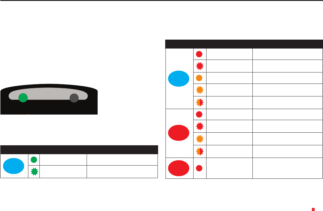
22
MU Status Lights
You’ll nd the two MU status lights on the top of the tool, above
the MU buttons. (See General Layout on page 9).
To view the MU status lights, hold the tool so that the charger
socket points away from you.
(The same lights are used when you are in RAM/EMMO mode,
but are labelled the other-way-round. (See RAM Status Lights
on page 23).
The MU OK light conrms that the MU or TU has not been
tampered:
Button Colour Meaning
GET
STATUS
Green MU/TU OK, no tamper
Flashing Green Tool connecting to MU/TU
The meaning of the MU FAULT light changes depending on
the button that you have just pressed.
(See MU Buttons on page 21).
Button Colour Meaning
GET
STATUS
Red Tool–to–MU/TU link fault
Flashing Red MU/TU tampered
Amber AC power not connected
Flashing Amber Low battery
Flashing Red/Amber MU/TU radio fault
MU
OFF
Red Tool–to–MU/TU link fault
Flashing Red AC power still connected
Flashing Amber Modem in use
Flashing Red/Amber MU/TU fault
FORCE
DIAL Red Tool–to–MU/TU link fault
OK MU FAULT
EMMO RAM
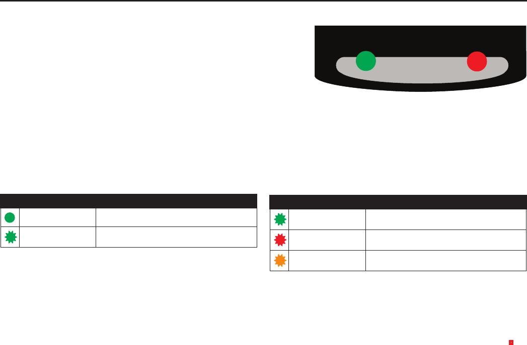
23
RAM Status Lights
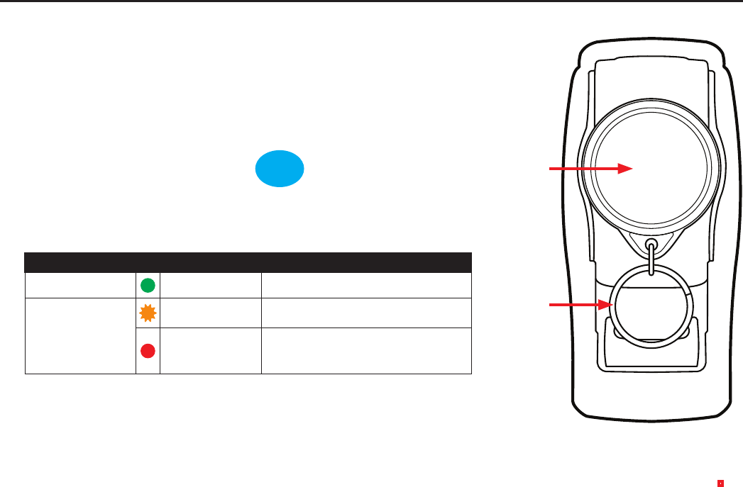
The EMMO light is green when the tool is in EMMO Mode.
(It blinks green when the tool is communicating with the PDA).
Colour Meaning
Green Tool in EMMO mode
Flashing Green Tool communicating with PDA
The RAM light blinks every time that it receives a radio signal
from an active tag during a RAM survey.
The colour of the blink shows the status of each detected tag:
Colour Meaning
Green Blink Active tag found, no tamper
Red Blink Tampered tag found
Amber Blink Tag with low battery found
The RAM Status Lights are used when you are Performing a
RAM Survey (see page 47), or are linking to a PDA running the
EMMO software. (See the EMMO User Guide).
To view the EMMO status lights, hold the tool so that the
charger socket points towards you.
(The same lights are used when you communicate with the MU
or TU, but are labelled the other-way-round.
(See MU Status Lights on page 22).
OK MU FAULT
EMMO RAM

24
This section tells you how to use the tool to install monitoring
equipment. It contains the following pages:
MU/TU-Dock Positioning Tips (page 25)
Initialising an MU (page 26)
Initialising a TU (page 27)
Getting a GPS Location Fix (page 28)
Preparing Straps for Installation (page 29)
Fitting a PID to a Subject (page 30)
Fitting a SOLO to a Subject (page 33)
MU Range Survey and Data Upload (page 37)
TU Range Survey and Data Upload (page 39)
Installing Monitoring Equipment

25
MU/TU-Dock Positioning Tips
Remember the following tips when installing an MU or a
TU-Dock:
Dos
9Position the MU/Dock as near to the centre
of the house as possible. (See right).
9Position the MU/Dock near to a mains electricity socket
(and telephone socket if installing a landline MU).
9Place the MU/Dock on a stable, level surface such as a table.
Don’ts
8Don’t position MUs/Docks on window-ledges
or next to outside walls.
8Don’t position MUs/Docks directly on the oor.
8Don’t create trip-hazards by trailing
power or telephone cables across the oor.
8Don’t position MUs/Docks near metal
objects such as heating radiators.
8Don’t position MUs/Docks on or near electrical
equipment such as microwave ovens or loudspeakers.
MU/TU-Dock
Reception
Range
Typical installation position using a
single MU/TU-Dock in a 2-storey house.

26
Initialising an MU
1. Phone the monitoring centre and give them
the MU and PID/SOLO’s serial numbers.
2. Multicom/Landline MU ONLY—Connect an ordinary
phone to the phone line and check that the line is active.
DO NOT connect the MU to the phone line at this stage.
3. Place the MU in a suitable location and plug it into the mains
power supply. (See MU/TU-Dock Positioning Tips on page
25).
Multicom/GSM MU ONLY—The MU will automatically
start to initialise and register with the GSM mobile
network.
If the MU displays “NO GSM SIGNAL”,
move the MU to a different location.
4. While the MU is initialising, measure the subject’s ankle and
select the correct size of strap. (See Preparing Straps for
Installation on page 29).
5. Next, t either a PID or a SOLO tag to the subject.
(See Fitting a PID to a Subject on page 30,
or Fitting a SOLO to a Subject on page 33).
Initialising Monitoring Unit
. . . . . . . . . . . .
27
Initialising a TU
SEARCHING FOR
A PID IN
SURVEY MODE
1. Phone the monitoring centre and give them the TU, Dock
and PID serial numbers.
2. Place the Dock in a suitable location and plug it into the
mains power supply. (See MU/TU-Dock Positioning Tips
on page 25).
3. Place the TU into the Dock. (Figure 1)
The TU automatically starts to initialise and register with
the GSM mobile network, and starts to search for a PID in
survey mode. (Figure 2)
If the TU displays “NO GSM SIGNAL”, leave the
TU docked and move the docking station to a different
location.
If the TU displays “REMOVE UNIT AND GET GPS”,
lift the TU from the dock and take it outside. (See Getting
a GPS Location Fix on page 28).
4. While the TU is initialising, measure the subject’s ankle and
select the correct size of strap. (See Preparing Straps for
Installation on page 29).
5. Next, t the PID to the Subject’s ankle,
(See Fitting a PID to a Subject on page 30).
Figure 1—Place TU in Dock
Figure 2—Searching for PID

28
After the TU has connected to the GSM network (see
Initialising a TU on page 27) it will attempt to get a GPS
location x.
If the TU displays REMOVE UNIT AND GET GPS
(Figure 1) the GPS signal is too weak indoors, and you must
take the unit outside to get a GPS x.
To Get a GPS Fix:
1. Lift the TU from the Dock and take it outside to an area
with a wide, clear view of the sky, away from any tall
buildings.
2. Stay still until the tracker displays
GPS OK: PUT UNIT BACK IN CRADLE. (Figure 2)
3. Go back indoors and place the TU back into its dock.
4. While the TU continues to initialise, measure the subject’s
ankle and select the correct size of strap. (See Preparing
Straps for Installation on page 29).
5. Next, t the PID to the Subject’s ankle,
(See Fitting a PID to a Subject on page 30).
Getting a GPS Location Fix
GPS OK:
PUT UNIT BACK
IN CRADLE
Figure 2—GPS OK
REMOVE UNIT
AND GET GPS
Figure 1—Get GPS Location Fix
29
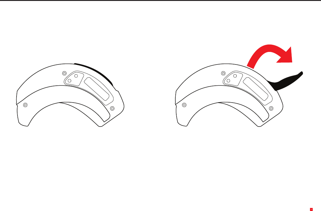
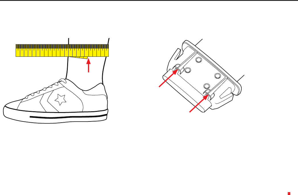
Preparing Straps for Installation
1. Measure the subject’s ankle and select the correct size of
strap. (Figure 1)
Figure 2—Fold down the two tabs on both strap clips
Figure 1—Measure the subject’s ankle
30
31
29
28
27
26
25
37
38
36
35
34
33
32
44
45
43
42
41
40
39
46
47
2. When you have selected a strap of the correct length, fold
down the two tabs on the ends of each clip. (Figure 2)
30
Before tting a PID to a subject, select and prepare the correct
size strap. (See Preparing Straps for Installation on page 29).
Make sure that the MU or TU is initialised. (See Initialising an
MU on page 26, or Initialising a TU on page 27).
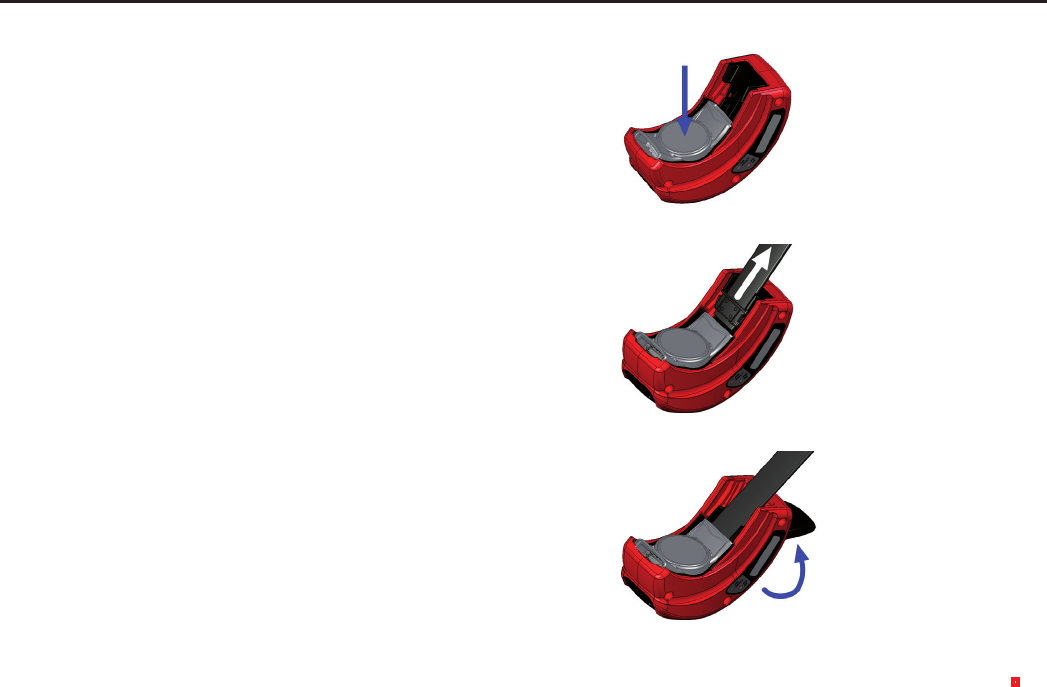
1. With the Strap Fitting Lever closed, click the PID into the
tool. (Figure 1)
2. Push one end of the strap between the tool’s jaws.
3. Pull on the free end of the strap so that the clip is tight
against the jaws. (Figure 2)
4. Open the Strap Fitting Lever, until you hear a click.
(Figure 3)
The strap is now tted in one end of the PID.
Continued on next page.
Fitting a PID to a Subject
Figure 1
Click PID into Tool
Figure 2
Pull on free end of strap
Figure 3
Open the strap-tting-lever
PID SLEEP
/ FAULT
PID
OK
31
Fitting a PID to a Subject (continued)
5. Check that the PID SLEEP/FAULT light is ashing red.
6. Close the Strap Fitting Lever and remove the PID and strap
from the tool. (Figure 4)
7. Pull the end of the strap to make sure that it is securely
tted into the PID.
8. Push the free end of the strap between the tool’s jaws.
9. Pull on the strap so that the clip is tight against the jaws.
(Figure 5)
Continued on next page.
Figure 5
Pull on free end of strap
Figure 4—Remove PID and strap from tool

PID SLEEP
/ FAULT
PID
OK
32
10. Holding the tool, wrap the strap and PID around the
subject’s ankle and click the PID into the Installation Tool.
(Figure 6)
11. Open the Strap Fitting Lever, until you hear a click.
The strap should be tted securely
around the subject’s ankle.
12. Check that the PID OK light is ashing green.
13. Close the Strap Fitting Lever and remove the tool from
the PID. (Figure 7)
14. Pull on the ends of the strap to make sure that it is securely
tted into the PID.
15. Next, perform a Range Survey.
(See MU Range Survey and Data Upload on page 37,
or TU Range Survey and Data Upload on page 39).
Fitting a PID to a Subject (continued)
Figure 6
Wrap strap
around
subject’s
ankle
Figure 7
Remove the
tool from the
PID

33
Fitting a SOLO to a Subject
Before tting a SOLO to a subject, select and prepare the correct
size strap. (See Preparing Straps for Installation on page 29).
SOLO tags can be either installed on their own, or with an MU. If
you are installing a SOLO with an MU, make sure that the MU has
been initialised. (See Initialising an MU on page 26).
1. Phone the Monitoring Centre and
give them the SOLO’s serial number.
2. With the strap-tting-lever closed,
click the SOLO into the tool. (Figure 1)
3. Push one end of the strap
between the tool’s jaws.
4. Pull on the free end of the strap so that the
clip is tight against the tool’s jaws. (Figure 2)
Figure 1
Click SOLO
into Tool
Figure 2
Pull on free
end of strap
Continued on next page.
34
5. Open the strap-tting-lever
until you hear a click. (Figure 3)
The strap is now tted in one side of the SOLO.
6. Check that the PID SLEEP
/FAULT light is ashing red.
7. Close the strap-tting-lever and remove
the SOLO and strap from the tool. (Figure 4)
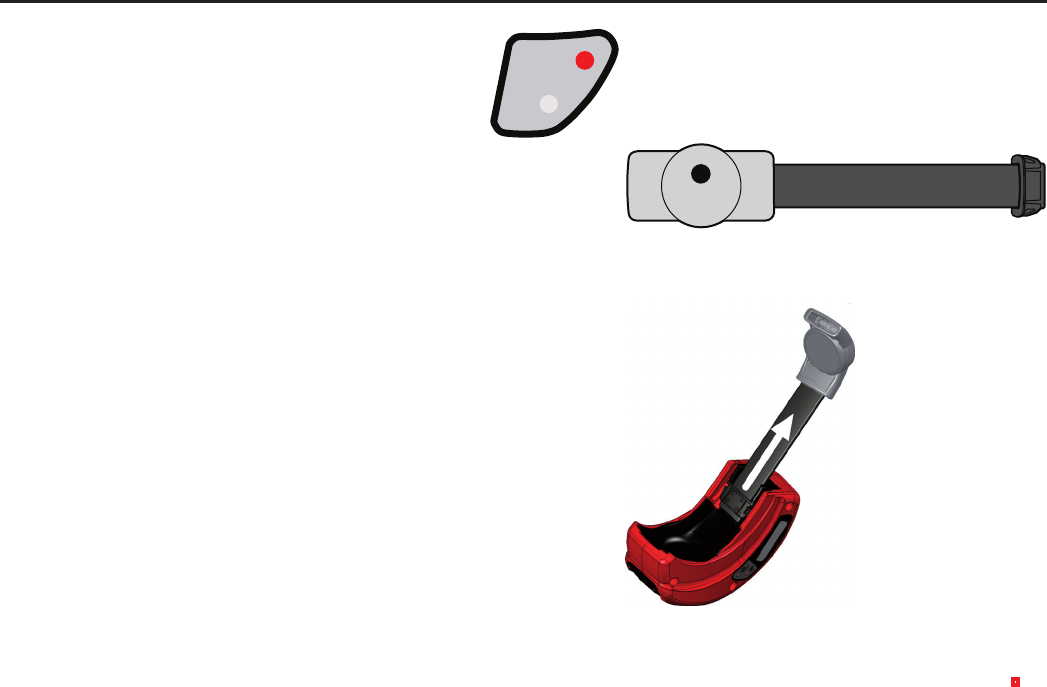
8. Check that the light on the
SOLO is ashing amber.
9. Pull on the free end of the strap to make
sure that it is securely tted into the SOLO.
Fitting a SOLO to a Subject (continued)
PID SLEEP
/ FAULT
PID
OK
Figure 3
Open the strap-
tting-lever
Figure 4
Remove SOLO and strap from tool
Flashing Amber Light
Continued on next page.

35
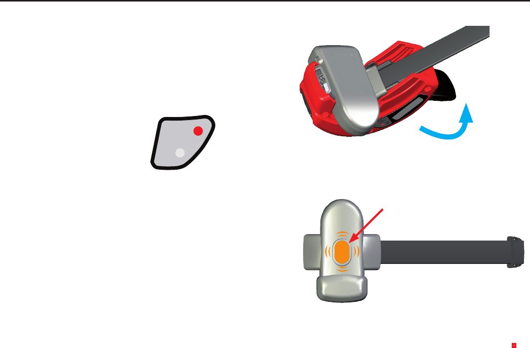
Fitting a SOLO to a Subject (continued)
10. Push the free end of the strap
between the tool’s jaws.
11. Pull on the strap so that the clip is tight
against the tool’s jaws. (Figure 5)
12. Wrap the strap and SOLO around the subject’s ankle
and click the SOLO into the tool. (Figure 6)
!Make sure that the round end
of the SOLO is pointing upwards.
13. Open the strap-tting-lever
until you hear a click.
The strap is now tted securely
around the subject’s ankle.
Figure 5
Pull on free
end of strap
Figure 6
Wrap strap
around
subject’s ankle
Continued on next page.
36
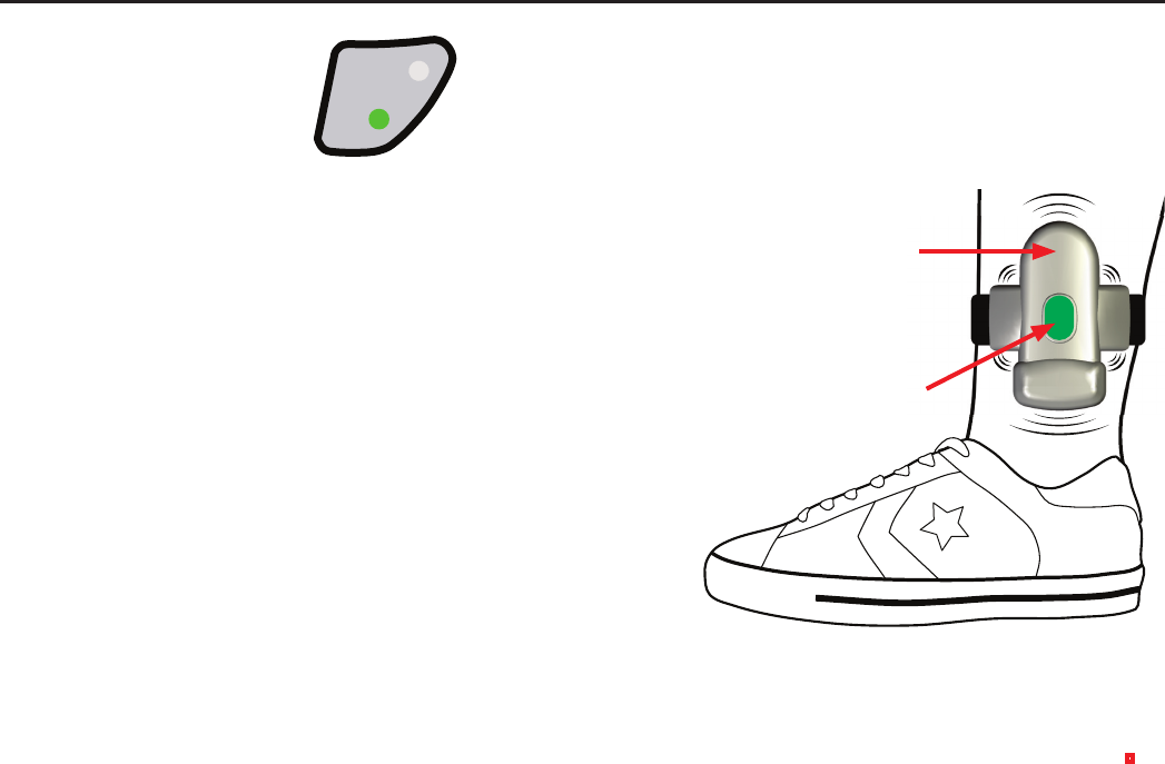
14. Check that the PID OK
light is ashing green.
15. Close the strap-tting-lever and remove
the tool from the SOLO. (Figure 7)
16. Pull on the strap to make sure that both
ends are securely tted into the SOLO.
The SOLO ashes amber while it
contacts the monitoring server.
When the installation details are uploaded,
the SOLO vibrates for 5 seconds and a
constant green light shines for 10 seconds.
17. If the SOLO is being installed on its own, when the green
light on the SOLO goes out, the installation is complete.
18. If you are installing the SOLO with an MU, you must
perform an MU range survey. (See MU Range Survey and
Data Upload on page 37).
PID SLEEP
/ FAULT
PID
OK
Figure 7—Remove the tool from the SOLO
Vibrates
(5 seconds)
Green Light
(10 seconds)
Fitting a SOLO to a Subject (continued)
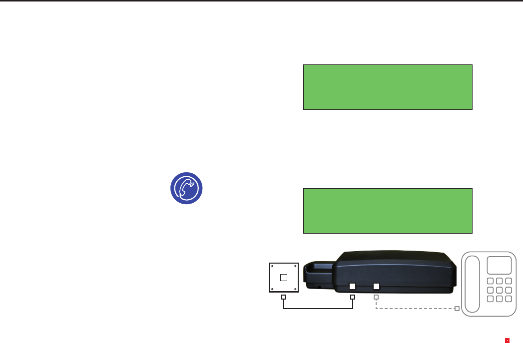
Phone Line In Phone Extension
Multicom/Landline MU Connections
37
MU Range Survey and Data Upload
When the MU has initialised and a new PID or SOLO has been
tted to the subject, the MU automatically goes into Survey Mode.
(See Initialising an MU on page 26, and either Fitting a PID to a
Subject on page 30, or Fitting a SOLO to a Subject on page 33).
1. The MU starts beeping and displays the new tag’s serial number.
2. Walk the subject around all areas of the premises.
The MU beeps every time that it receives a
radio signal from the tag in survey mode.
!The MU should beep every second.
A ‘missed’ beep shows a possible blind-spot.
3. When the survey is complete,
press the blue button on the MU.
The MU displays the MU and tag serial numbers,
and the survey ranges (R1 and R2)
4. Phone the monitoring centre on your mobile
and tell them the range values (R1 and R2).
5. Multicom/Landline MU ONLY
Connect the MU to the phone line wall socket
and connect the extension phone to the MU.
SURVEY P205764
Press BLUE button when walk
around complete
MU20634 P205764 R1=180 R2=190
Press BLUE button when call
complete
Continued on next page.

38
MU Range Survey and Data Upload (continued)
Calling Control
Waiting for PID Message
13:26:37
06/09/2011
PID Install OK
P205764 R1=180 R2=190
6. When you have completed your call to the
monitoring centre, press the blue button
on the MU again.
The MU tries to call Control, and displays:
Calling Control - Connecting.
If the call connects successfully, the MU displays:
Calling Control – Transferring.
The MU should then display:
Calling Control – Call connected OK.
The MU beeps, and starts to download the range setting
and PID serial number from the Control Centre.
When the download is complete, the MU beeps three
times and displays the PID Install OK message for 20
seconds.
The installation is complete.
The MU displays the current date and time.
(If you do not see the PID Install OK message,
see MU Error Messages on page 50).
Calling Control
Call Connected OK
Calling Control
Connecting
Calling Control
Transferring

39
TU Range Survey and Data Upload
When the TU has initialised and a new PID has been tted to the
subject, the TU automatically goes into Survey Mode. (See Initialising
a TU on page 27, and Fitting a PID to a Subject on page 30).
1. The TU displays WALK AROUND WITH PID
and the PID’s serial number.
2. Leaving the TU docked, walk the subject
around all areas of the premises.
The TU beeps every time that it receives a
transmission from the PID in survey mode.
!The TU should beep once every second.
A ‘missed’ beep shows a possible blind-spot.
3. When the survey is complete,
press the left-hand button on the TU.
The TU beeps and displays the TU and DOCK serial numbers.
4. Press the right-hand button to view the
PID’s serial number and the survey ranges:
5. Phone the monitoring centre on your mobile
and tell them both range settings.
6. When you have completed your call to the monitoring centre,
press the right-hand button on the TU again.
Continued on next page.
CALL CENTRE INFO
TU: 500076
DOCK: 540077
WALK AROUND
WITH PID
222771
CALL CENTRE INFO
PID: 222771
RANGE 1: 180
RANGE 2: 190

40
TU Range Survey and Data Upload (continued)
The TU tries to call Control, and displays:
CONNECTING.
If the call connects successfully, the TU displays:
TRANSFERRING
The TU beeps, and starts to download the range setting
and PID serial number from the Control Centre.
When the download is complete, the TU displays
INSTALLATION SUCCESSFUL for 20 seconds.
The installation is complete.
The TU displays the current time.
If you do not see the INSTALLATION SUCCESSFUL
message, see the TU Error Messages on page 52
CONNECTING
TRANSFERRING
INSTALLATION
SUCCESSFUL
TU ACTIVE
11:59

PID SLEEP
/ FAULT
PID
OK
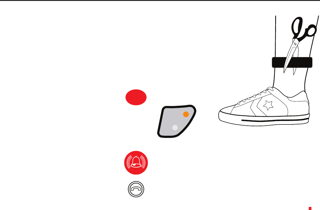
42
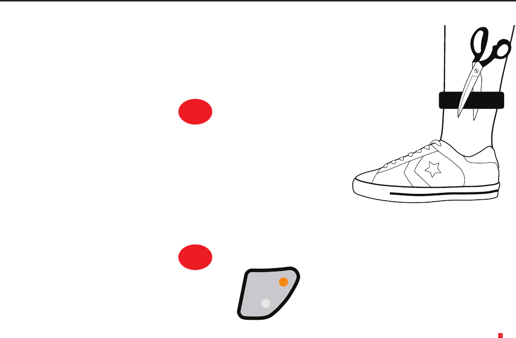
To abandon an install at any point:
1. Remove the Tag
Cut the middle of the strap with scissors and remove
the PID or SOLO from the subject. (Figure 1)
!Note: It is impossible to switch the tag to sleep
mode, unless the strap has been cut or opened.
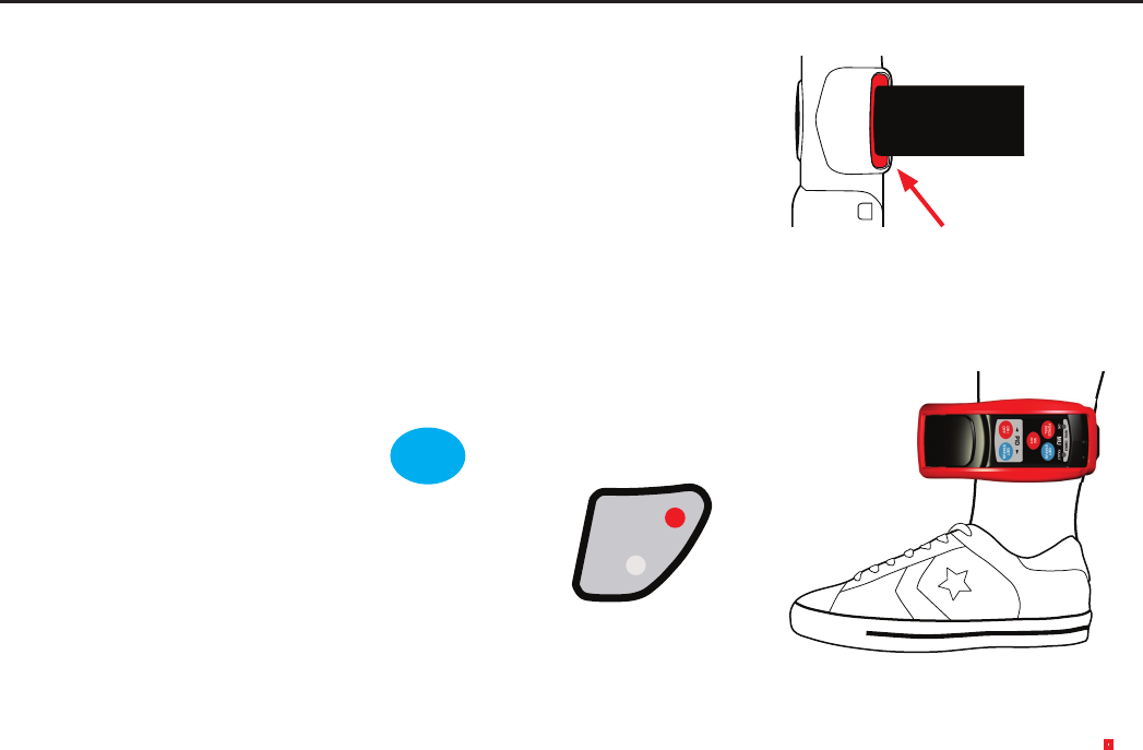
2. Switch Off the Tag
Clip the tool over the PID/SOLO.
Press the PID ON/OFF button.
The PID SLEEP/FAULT light on the side of the tool
shines amber to show that the tag is in sleep mode,
then starts ashing red to indicate a strap-cut tamper.
(See PID Status Lights on page 20).
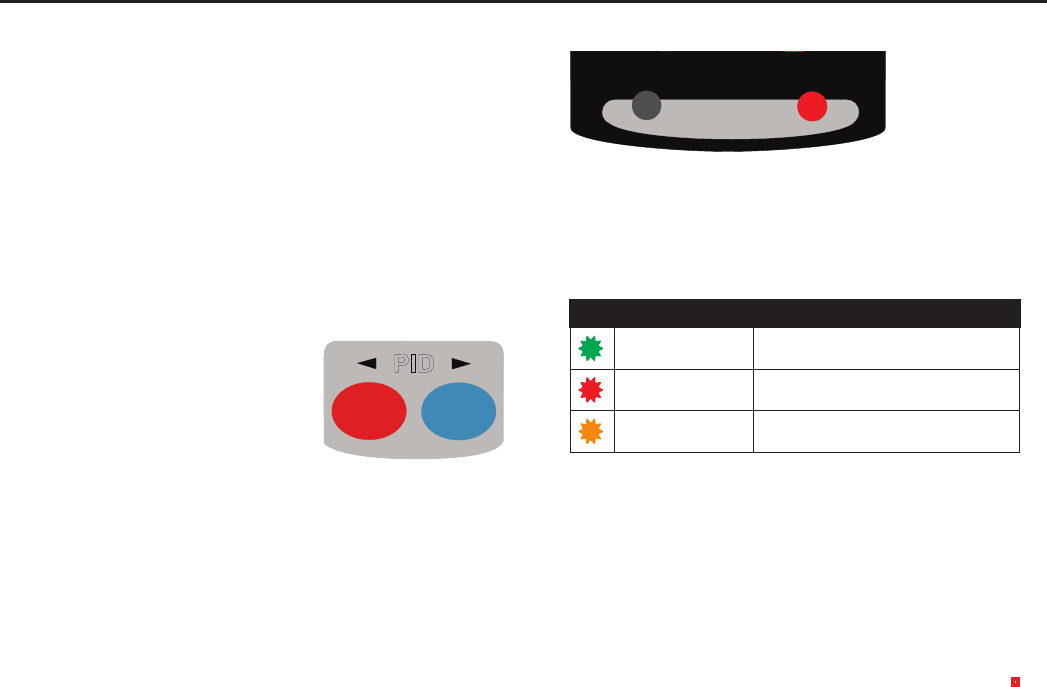
3. Reset the MU or TU
Press the red button on the MU.
Or:
Press the right-hand button on the TU.
Abandoning an Install
ON/
OFF
Figure 1
Cut middle
of strap with
scissors
PID SLEEP
/ FAULT
PID
OK
43
Follow the steps below to remove a tag at the end of a curfew period:
1. Switch Off the MU or TU
Unplug the MU or docking station from the mains power supply.
Point the tool at the front of the MU or the bottom of the TU.
(See Linking to MUs on page 14, or Linking to TUs on page 15).
Press the MU OFF button.
2. Remove the Tag
Cut the middle of the strap with scissors and remove
the PID or SOLO from the subject. (Figure 1)
!Note: It is impossible to switch the tag to sleep
mode, unless the strap has been cut or opened.
3. Switch Off the Tag
Clip the tool over the PID or SOLO.
Press the PID ON/OFF button.
The PID SLEEP/FAULT light on the side of the tool
shines amber to show that the tag is in sleep mode,
then starts ashing red to indicate a strap-cut tamper.
(See PID Status Lights on page 20).
Removing a Tag
MU
OFF
ON/
OFF
Figure 1
Cut middle
of strap with
scissors

44
Follow the steps below to replace a tampered or faulty PID:
1. Switch off the MU or TU. (See Removing a Tag on page 43).
2. Cut the middle of the strap with scissors
and remove the tag from the subject. (Figure 1)
3. Put the PID into sleep mode. (Clip the tool over the tag
and press the PID ON/OFF button).
4. Phone the monitoring centre and tell
them the new tag’s serial number.
5. Plug the MU or docking station back into the mains power
supply.
6. Fit the new tag to the subject. (See Fitting a PID to a Subject
on page 30, or Fitting a SOLO to a Subject on page 33).
7. Continue with the rest of the install procedure. (See MU
Range Survey and Data Upload on page 37, or TU Range
Survey and Data Upload on page 39).
Replacing a Tag
ON/
OFF
Figure 1
Cut middle
of strap with
scissors

46
Investigating Tamper Alerts
Follow the steps below when you need to investigate a tamper alert:
!DO NOT remove the tag from the subject’s leg before
checking the tag and strap for signs of tampering.
1. Inspect the tag and strap for signs of tampering:
Check that both ends of the strap are secured.
Check if the strap clips are damaged. (Figure 1)
Check that the strap has not been cut, torn or frayed.
Check for cracks, dents and scratches on the outer casing.
Check for clear or white glue residue.
2. Clip the tool over the tag. (Figure 2)
3. Press the PID GET STATUS button.
4. Check the PID SLEEP/FAULT and PID OK lights on the
side of the tool. (See PID Status Lights on page 20).
5. Further checks can be carried out using EMMO.
(See the EMMO User Guide).
Figure 2
Clip the tool
over the tag
Figure 1
Check strap
clips for
damage
GET
STATUS
PID SLEEP
/ FAULT
PID
OK
PID
GET
STATUS
ON/
OFF
47
RAM (Random Alternative Monitoring) mode allows you to nd
out if there are any PIDs or SOLOs nearby. You can perform a
RAM using the tool on its own to quickly detect any tags and get
their tamper status.
Use the EMMO software running on a PDA to get the full details
of any detected tags (See the EMMO User Guide).
To Put the Tool into RAM Mode:
1. Press and hold down the
PID GET STATUS
button for 3 seconds.
2. While still holding down the
PID GET STATUS button,
press the PID ON/OFF button.
Performing a RAM Survey
The RAM light blinks every time a tag’s radio signal is
detected. The colour of the blink shows the status of each
detected tag:
RAM Light Meaning
Green Flash Active tag found, no tamper.
Red Flash Tampered tag found.
Amber Flash Tag with low battery found.
Each active tag transmits a radio signal every 10 seconds.
For example, if the tool detects only one tag, the RAM
light blinks once every 10 seconds. If there are two tags
nearby, the RAM light blinks twice every 10 seconds etc.
OK MU FAULT
EMMO RAM


49
Installation Tool Errors
Error Cause Action
Unable to switch on Tool, no lights or beeps. Flat battery. Charge the battery (see page 10).
Battery Status Light is ashing red or amber.
Tool won’t wake up from Sleep Mode:
All the lights ash red one after another,
and the Tool returns to Sleep Mode.
Missing or faulty ofcer’s key fob.
Make sure that a red key fob is nearby, and is
ashing every 10 seconds.
(See FMO’s Key Fob on page 12).

50
MU Error Messages
Continued on next page.
Error Cause Action
NO GSM SIGNAL!
Move unit to different
location
Poor GSM (mobile phone) signal. Move the MU to a location with better GSM reception.
MU FAIL!
No GSM Signal
CALL FAILED!
MU FAIL!
Return to GML MU Failure.
Check that the MU is connected to the mains power.
Check the MU’s status using EMMO, (see the EMMO User Guide)
which may indicate possible interference (MU status codes J1/J2).
Possible causes may include faulty car-remote key fobs.
If the MU still fails, return it for servicing.
PID INSTALL FAILED
PID not in list
The number of the PID just installed on
the MU does not match the PID number
entered by the monitoring centre.
Call the monitoring centre and check that they have entered
the correct PID and MU serial numbers.
PID INSTALL ABANDONED The red button on the MU was pressed
during the install. Restart the installation from the beginning.

51
MU Error Messages (continued)
Error Cause Action
MORE THAN 1 PID IN
SURVEY
The MU has detected more than 1 PID in
survey mode.
Switch off or remove the extra PID(s) and restart the installation from
the beginning.
PID INSTALL FAILED
PID not seen Possible PID number mismatch and/or
GSM problem.
Call the monitoring centre and check that they have entered the
correct PID and MU serial numbers.
If the MU and PID numbers are correct, switch off the MU, move it to
a different location and restart the installation from the beginning.
PID INSTALL FAILED
Communications fail
PID INSTALL ABANDONED
PID TAMPER DETECTED PID is transmitting a tamper message. Restart the installation from the beginning using a PID that is not in a
tamper condition..
Line busy
Busy/engaged messages. Wait for a moment and try again.
Line engaged
BAD PUK
SIM card errors. Return MU for servicing.
BAD PIN
Reg Err

52
TU Error Messages
Error Cause Action
PLACE UNIT IN
CHARGING STATION TU not docked correctly. Re-dock the TU in the docking station ensuring the contact is rm and
secure.
NO GSM SIGNAL
RE-POSITION UNIT
Poor GSM (mobile phone) signal. Move the docked TU to a location with better GSM reception.
CONNECTION FAIL
REMOVE UNIT AND GET GPS Poor GPS (satellite tracking) signal.
Lift the TU from the Dock and take it outside to an area with a wide,
clear view of the sky, away from any tall buildings. (See Getting a
GPS Location Fix on page 28).
MORE THAN 1 PID IN SURVEY The TU has detected more than 1 PID in
survey mode.
Switch off or remove the extra PID(s) and restart the installation from
the beginning.
FAILED - PID NOT IN LIST
The PID number just installed on the TU
does not match the PID number entered
by the monitoring centre. Call the monitoring centre and check that they have entered
the correct PID and TU, and DOCK serial numbers.
FAILED - DOCK NOT IN LIST
The DOCK number just installed on the
TU does not match the DOCK number
entered by the monitoring centre.
INSTALLATION ABANDONED The installation was manually abandoned. Restart the installation from the beginning.
Continued on next page.

53
TU Error Messages (continued)
Error Cause Action
FAILED - PID NOT SEEN
Possible PID number mismatch and/or
GSM problem.
Call the monitoring centre and check that they have entered the
correct PID and TU serial numbers.
If the TU and PID numbers are correct, unplug the docking station,
switch off the TU, move it to a different location and restart the
installation from the beginning.
FAILED TO CONTACT SERVER
PID IS TAMPERED PID is transmitting a tamper message. Restart the installation from the beginning using a PID that is not in a
tamper condition.
DOCK IS TAMPERED DOCK is transmitting a tamper message. Restart the installation from the beginning using a DOCK that is not in
a tamper condition.
NO SIM CARD RETURN UNIT
Faulty/missing SIM in TU. Return TU for servicing.
SIM LOCKED FAULT
RETURN UNIT
RADIOS ARE JAMMED Radio interference.
Move the docking station or remove the source of the radio
interference and restart the installation from the beginning. (Possible
causes may include faulty car-remote key-fobs).
TRACKER FAULT
RETURN UNIT TU Failure.
Return TU for servicing.
!The TU will shut down after 10 seconds if
it is not docked correctly while in this state.

54
A
Abandoning an Install 42
B
BAD PIN 51
BAD PUK 51
Battery 10
Charging 10
Key Fob 13
Status Light 9, 10
Button
Force Dial 21
Get Status 19, 21
MU Off 21
On/Off 19
Buttons
MU 21
PID 19
C
Call Connected OK 38
CALL FAILED! 50
Calling Control 38, 40
Charger Socket 9, 10
CHARGING STATION 52
Charging the Battery 10
Checking the Key Fob’s Battery 13
Communications fail 51
Connecting 38
CONNECTION FAIL 52
Controls 17
D
DOCK 6
DOCK IS TAMPERED 53
E
EMMO 6
EMMO Light 23
Error Messages, MU 50, 51
Error Messages, TU 52, 53
Errors, Installation Tool 49
F
FAILED - DOCK NOT IN LIST 52
FAILED - PID NOT IN LIST 52
FAILED - PID NOT SEEN 53
FAILED TO CONTACT SERVER 53
Field Monitoring Ofcer 5
Fitting a SOLO to a Subject 33, 34, 35, 36
Fitting the PID to the Subject 30, 31, 32
FMO 6
FMO’s Key Fob 12
FORCE DIAL button 21
G
General Layout 9
Get Status Button 19, 21
Getting a GPS Location Fix 28
Getting Started 8
GPRS 6
GPS 6, 28
GPS OK: 28
GSM 6
Index

55
I
Infrared Port 9
Infrared Window 14, 15
Initialising an MU 26
Initialising a TU 27
Initialising Monitoring Unit 26
Install, Abandoning 42
INSTALLATION ABANDONED 52
Installation, Preparing Straps for 29
Installation Tool Errors 49
Introduction 4
Investigating Tamper Alerts 46
IrDA 6
K
Key Fob 12
Key Fob Batteries 12
Key Fob’s Battery 13
L
LBS 6
Light
EMMO 23
MU FAULT 22
MU OK 22
PID OK 20
PID SLEEP/FAULT 20
RAM 23
Lights
MU Status 22
PID Status 20
RAM Status 23
Line Busy 51
Line Engaged 51
Linking to the MU 14
Linking to the TU 15
M
MORE THAN 1 PID IN SURVEY 51, 52
Move unit to different location 50
MU 6
MU Buttons 9, 21
MU Error Messages 50, 51
MU FAIL! 50
Index (continued)
MU FAULT Light 22
MU, Initialising an 26
MU, Linking to 14
MU OFF button 21
MU OK light 22
MU/RAM Status Lights 9
MU Range Survey and Data Upload 37, 38
MU Status Lights 22
MU/TU-Dock Positioning Tips 25
N
NO GSM SIGNAL! 50
NO GSM SIGNAL RE-POSITION UNIT 52
NO SIM CARD RETURN UNIT 53
O
OM247-MU 6
OM247-PID 6
OM247-SOLO 6
OM247-TRAK 6
ON/OFF button 19
Overview 7

56
Index (continued)
P
PDA 6
Performing a RAM Survey 47
PID 6
Buttons 9, 19
Removing 43
Replacing 44
Status Lights 9, 20
PID INSTALL ABANDONED 50, 51
PID INSTALL FAILED 50, 51
PID Install OK 38
PID IS TAMPERED 53
PID not in list 50
PID not seen 51
PID OK Light 20
PID SLEEP/FAULT Light 20
PID TAMPER DETECTED 51
PLACE UNIT IN CHARGING STATION 52
Positioning Tips 25
Preparing Straps for Installation 29
PUT UNIT BACK IN CRADLE 28
R
RADIOS ARE JAMMED 53
RAM 6
RAM Light 23
RAM Mode 47
RAM Status Lights 9, 23
Reg Err 51
REMOVE UNIT AND GET GPS 28, 52
Removing and Replacing Tags 41
Removing a PID 43
Removing a Tag 43
Replacing a PID 44
Replacing a Tag 44
Return to GML 50
S
SIM LOCKED FAULT RETURN UNIT 53
Sleep Mode 11
SOLO 6
Strap Fitting Jaws 9
Strap Fitting Lever 9, 18
Subject 6
Subject, Fitting a SOLO to a 33, 34, 35, 36
Subject, Fitting the PID to the 30, 31, 32
Survey, Performing a RAM 47
T
Tag 6
Tag, Removing a 43
Tag, Replacing a 44
Tags, Removing and Replacing 41
Tamper Investigation 45
Tamper Investigation and RAM Survey 45
Telephone Number 2
TRACKER FAULT RETURN UNIT 53
Transferring 38
Trouble Shooting Guide 48
TU 6
TU Error Messages 52, 53
TU, Initialising a 27
TU, Linking to 15
TU Range Survey and Data Upload 39, 40
U
Upload, MU Range Survey and Data 37, 38
Upload, TU Range Survey and Data 39, 40
Using the Installation Tool 24
W
Waiting for PID Message 38
Welcome 5