Gallagher Group G031404 Controller BR Series Reader User Manual 3E0680 SmartReader BR Series
Gallagher Group Ltd Controller BR Series Reader 3E0680 SmartReader BR Series
Contents
Part 2

3E0680 3E0680 SmartReader BR Series
Page 12
Using the SmartReader
Configuring the Electronic Controller for use
EachtimeyouwanttousetheSmartReaderyouneedtodetermine
how you are going to use it.
This determines:
•what device to connect to the Electronic Controller and
•what operating mode to set on the Electronic Controller.
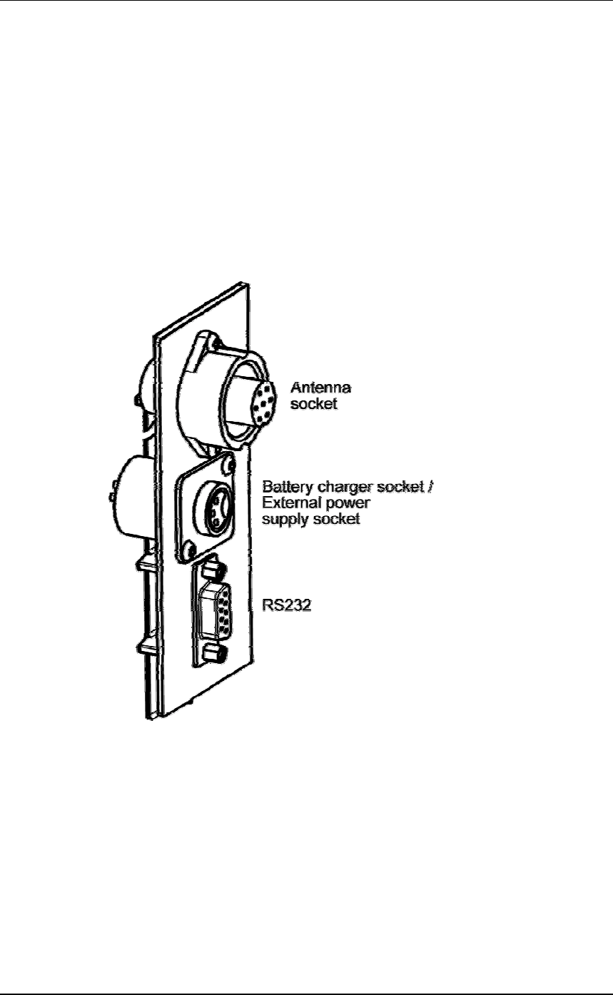
Setting up the Electronic Controller
For further details on the options described, see Electronic Controller
Connectors (p 9).
1. Are you connecting the Electronic Controller to an external device
(Scale or Computer)?
•If yes, go to step 2.
•If no, no set up is required.
2. Connect the Electronic Controller to an external device.
a. Ensure the Electronic Controller is turned off.
b. Plug the supplied serial cable into the serial port on the
Electronic Controller.
c. Plug the other end into the device and set it up to receive the
data.
Note:
•If your computer does not have a serial port, use the
supplied DB9 to USB adaptor to connect to a USB port on
the computer.
•If connecting to a Gallagher or Ruddweigh Scale, connect
the serial cable into COM Port 2 on the Scale and set the
port to EID Allflex in the Communications menu. See
your Scale manual for details.

3E0680 SmartReader BR Series 3E0680
Page 13
Setting the operating mode
For further details on the options described, see Electronic Controller
Features (p 4).
1. Do you want to save the Electronic ID tag number to the internal
memory?
•If yes, turn the dial to Memory. Gotonextstep.
Note: Data is stored in the internal memory and is also sent
out via the COM port in this mode.
•If no, turn the dial to On. Gotonextstep.
Note: Data is sent out via the COM port but is not stored in
the internal memory in this mode.
2. Doyouwanttoresetthecounter to zero on the Electronic
Controller?
•If yes, press the Reset Counter button. Go to next step.
•If no, go to next step.
3. Doyouwanttoaddthenewtagreadstotheexistingsession?
•If yes, end of procedure.
•If no, press the New Session button.
Note: A new session is always created when the Scale is
turned off then on.
Scanning Electronic ID tags
1. Begin scanning Electronic ID tags.
2. Do you want to add the new tag reads to a new session?
•If yes, press the New Session button. Go to step 3.
For further details, see Buttons (p 5).
•If no, go to step 3.
3. Continue until you have read all Electronic ID tags.

3E0680 3E0680 SmartReader BR Series
Page 14
Finishing a scanning session
1. Turn off the Electronic Controller.
2. If you had external devices connected to the Electronic Controller
disconnect them.
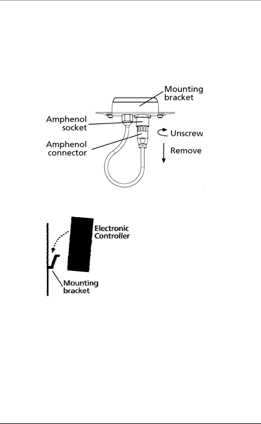
3. On the Electronic Controller, unscrew the Amphenol connector
locking nut and disconnect the antenna cable from the Electronic
Controller.
4. On the Electronic Controller, replace the cap onto the Amphenol
socket and tighten to protect from debris.
5. Grasp the Electronic Controller on both sides and lift up until it
clears the mounting bracket.
6. Screw the Amphenol connector on the antenna cable into the
Amphenol socket on the Antenna Panel and tighten the locking
nut.
Note: This helps keep the Amphenol connector free of dust
and debris.
For information on downloading data from the Electronic Controller
into MyScale Pro see MyScale Pro (p 42).
3E0680 SmartReader BR Series 3E0680
Page 15
Power options in BR Series SmartReader
Charging internal batteries
Note: The SmartReader will not operate with the battery charger connected.
To charge the internal batteries in the Electronic Controller, complete
the following steps:
1. Check the input voltage on the battery charger is correctly set (110
or 230 V AC).
2. Plug the battery charger into power socket and turn on.
3. Connect the battery charger in the Electronic Controller.
4. On the battery charger, switch the unit on.
5. Check the LED on the battery charger to ensure Electronic
Controller is being charged:
Notes:
•The battery charge time is approximately 6 hours.
•Once the battery is full charged the battery charger stops charging.
•The bargraph indicates the charge level by the number of static
bars. See Bargraph (p 7).
3E0680 3E0680 SmartReader BR Series
Page 16
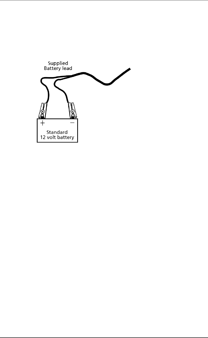
Connecting to an external 12 volt battery
To connect the Electronic Controller to an external 12 volt battery,
complete the following steps:
1. Connect the supplied black and red battery lead to the Electronic
Controller.
2. Connect the alligator clips to the 12 volt battery.
Connect the Red clip to the Positive terminal
Connect the Black clip to the Negative terminal.
Notes:
•The bargraph displays the level of charge in the
•external 12 volt battery, or
•internal battery
whichever is the greater.
•The internal batteries are not charged.

3E0680 SmartReader BR Series 3E0680
Page 17
Low voltage shutdown
When the battery charge (for the battery providing power to the
Electronic Controller) drops to below one bar the low battery beep
sounds (four beeps) to indicate the battery has low voltage. This will
continue regularly until the battery level becomes critical or until you
charge the battery.
This applies for both the internal and external (if connected) batteries.
When the battery charge (for the battery providing power to the
Electronic Controller) drops to a critical level, the Electronic
Controller shuts down. During the shut down process the low battery
beep sounds (four beeps) and the display shows BATT. The critical
level occurs when the battery voltage drops below 11.5 volts.
Replace the external battery or recharge the internal batteries.
For further information on connecting an external 12 volt battery, see
Connecting to an external 12 volt battery (p 16).
Note: This warning sounds regardless of the volume level setting.
High voltage shutdown
If the power source to the Electronic Controller provides a voltage
greater than 16 V, the Electronic Controller automatically shuts down
to protect the electronics. The display shows VOLT while shutting
down. For additional information, see Display (p 6).
3E0680 3E0680 SmartReader BR Series
Page 18
Installation
Connecting the Electronic Controller
batteries
During factory assembly, two batteries are installed in the Electronic
Controller. These batteries are not connected to the Electronic
Controller to preserve the battery prior to first use.
Once you are ready to use the Electronic Controller for the first time,
it is necessary to connect the batteries. You do not need to disconnect
the batteries again.
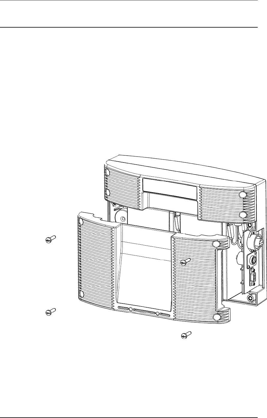
1. On a soft cloth, lay the Electronic Controller on its front.
2. Using a posi-drive screw driver, remove the screws holding the
lower back Antenna Panel of the Electronic Controller.
3. Remove the lower back Antenna Panel.
4. Remove the foam spacer between the batteries and retain.
5. Stand each battery up.
6. Connect the battery leads. Connect the longer leads to the left-
hand battery.
•Connect the Red lead to the red terminal.
•Connect the Black lead to the black terminal.

3E0680 SmartReader BR Series 3E0680
Page 19
7. Lay down the batteries with the:
•terminals to the top of the box and,
•the battery tops towards the connectors.
Note: Take care not to damage the terminals when replacing
the batteries
8. Refit the foam spacer between the two batteries.
Note: This foam stops the batteries moving and damaging
the terminals.
9. Replace the lower back Antenna Panel.
10. Replace the 4 posi-drive screws and tighten.
11. Charge the internal batteries to ensure they are fully charged ready
for use. See to Charging internal batteries (p 15).

3E0680 3E0680 SmartReader BR Series
Page 20
Mounting the Antenna Panel
Antenna Panel Kit
The Antenna Panel kit contains the following components:
•Antenna Panel
•Mounting instructions
•Antenna Panel mounting kit:
•4xWashersM8x21mmflatStainlesssteel
•4xBoltM8X70mmHEXStainlesssteel
•4 x Nut M8 HEX Stainless steel
•Screw Wood TEK 14 X 10 90mm
•Screw Wood TEK 14 X 10 65mm
Notes on locating the Antenna Panel
Gallagher recommends the following when installing the SmartReader
Antenna Panel:
•The Antenna Panel can be mounted onto metal pipe work or wood
of the animal handler but not solid steel handler walls.
•The edges of the Antenna Panel contain the antenna windings.
This means that when the Antenna Panel is mounted, vertical bars
should be kept away from the vertical edges of the Antenna Panel
and horizontal bars should be kept away from the horizontal edges
of the Antenna Panel.
Considerations
•The position of the Antenna Panel installation depends on the type
and size of the animals to be scanned and the size of Antenna
Panel to be installed.
•Gallagher recommends you mount the Antenna Panel temporarily
while you determine the most appropriate position.
•Mounting the Antenna Panel on a metal animal handler can alter
the read range of the SmartReader. Gallagher recommends that
the SmartReader is mounted on wood or spaced pipework.
•Multiple SmartReaders can be installed in close proximity to each
other, so long as they are synchronised to ensure conflict does not
occur between SmartReaders. See Installing multiple
SmartReader (p 36) for further details.
•Use the defined mounting holes, because drilling through the
Antenna Panel will damage the antenna.
3E0680 SmartReader BR Series 3E0680
Page 21
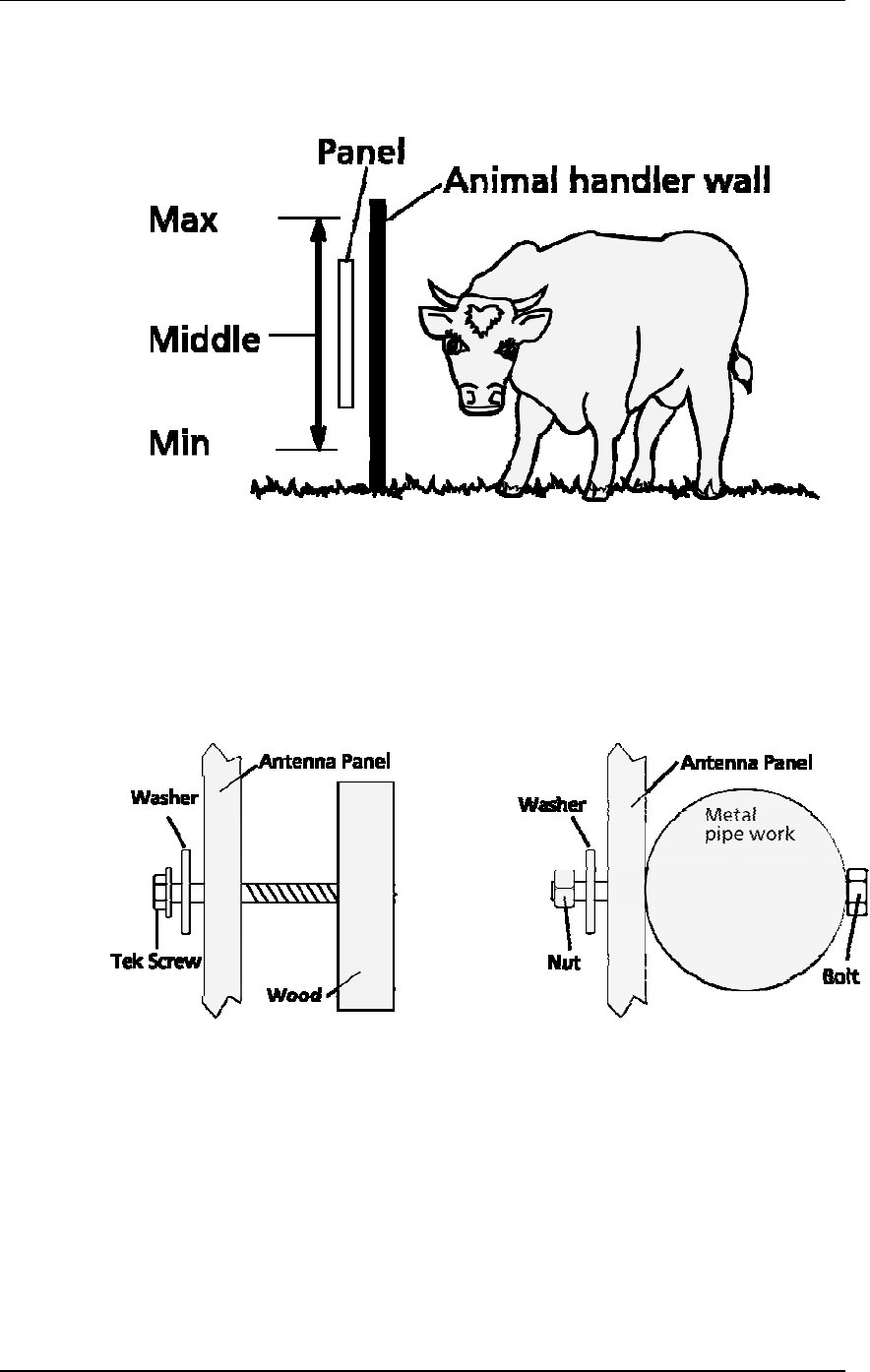
Procedure
1. Measure the vertical range of the Electronic ID tags on the
animals to be scanned.
2. Determine the average height of the Electronic ID and mark this
on the outside of the animal handler.
3. Determine what the Antenna Panel is to be mounted on, wood or
pipe work, and prepare the appropriate mounting hardware from
the supplied kit.
Wood - washers and tek screws Pipe work - washers, bolts and nuts
3E0680 3E0680 SmartReader BR Series
Page 22
4. Using the defined mounting holes, mount the Antenna Panel on
the outside of the animal handler so that the middle of the
Antenna Panel matches the average height.
Note: DO NOT drill through the Antenna Panel as it will
damage the antenna.
Note: You may want to temporarily attach the Antenna Panel and test the
read range prior to permanently attaching the Antenna Panel.

3E0680 SmartReader BR Series 3E0680
Page 23
Mounting the Electronic Controller
Considerations
•Ensure the mounting location of the Electronic Controller
provides protection from being knocked or damaged by animals.
•The Electronic Controller needs to taken away from the Antenna
Panel location to charge the internal batteries and to download the
Electronic ID data to computer.
Electronic Controller kit
The Electronic Controller kit contains the following components:
•BR Series Electronic Controller with internal batteries.
•Battery Charger
•MyScale Pro CD
•Instruction Manual (this manual)
•Cables
•Short serial cable (DB9 to DB9)
•Longserialcable(DB9toDB9)
•DB9toUSBadapter
•External battery cable (red and black)
•Mains power cord (Battery Charger)
3E0680 3E0680 SmartReader BR Series
Page 24
Connecting the Electronic Controller to the Antenna Panel
For information on using the Extension Mounting Kit see
SmartReader Extension Mounting Kit installation (p 76).
1. Ensure the Electronic Controller is turned off.
2. On the Antenna Panel, unscrew the Amphenol connector locking
nut from the Amphenol socket and pull it down to unplug from the
Antenna Panel.
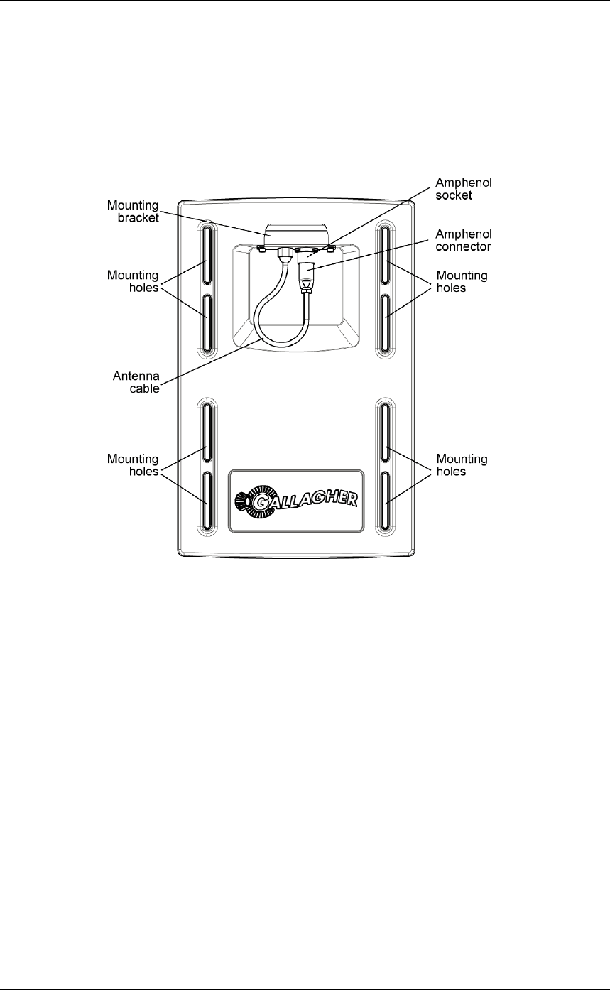
3. Mount the Electronic Controller on the mounting bracket by
grasping the Electronic Controller on both sides and slide the back
handle onto the mounting bracket.
3E0680 SmartReader BR Series 3E0680
Page 25
4. Connect the antenna cable to the Electronic Controller and tighten
the locking nut.

3E0680 3E0680 SmartReader BR Series
Page 26
Testing the SmartReader EID tag read
range
The SmartReader EID tag read range should be tested to ensure the
animals passing through the animal handler are accurately and reliably
identified.
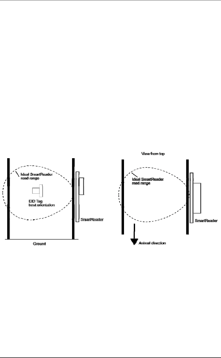
The SmartReader generates a balloon shaped read range (see diagram
next page), within which EID tags are read reliably. The size of the
read range for individual installations should be the width of the
animal handler.
The SmartReader EID tag read range for a particular installation is
tested using the built in set up mode in the SmartReader. This set up
mode changes how often the SmartReader beeps to confirm a tag read
from “only on first read” to ”every read”. This enables you to easily
test the SmartReader EID tag readrangeusingthesametag.
The following section describes how to complete an initial test on the
SmartReader EID tag read range for your SmartReader installation.
For more advanced testing see Advanced EID tag read range testing
(p 30).
Note: The SmartReader is shipped in Setup mode.
3E0680 SmartReader BR Series 3E0680
Page 27
Testing the read range
For your SmartReader installation youneedtodeterminethesizeof
the EID tag read range. If the read range is too small you need to take
steps to improve it.
You need to test the appropriate type of EID tag you will be using,
either HDX (Half duplex) and/or FDX (Full duplex).
To determine the size of your installation’s SmartReader EID tag read
range, complete the following steps:
1. Turn on the SmartReader.
2. Ensure the SmartReader is in set up mode by holding an EID tag
in front of the SmartReader.
•If the SmartReader beeps continuously it is in set up mode.
•If the SmartReader beeps once it is in operational mode.
3. Hold the EID tag in the best orientation in the animal handler near
theSmartReaderAntennaPanel.
The SmartReader should beep indicating it is reading the EID tag.
4. Move the EID tag around to determine the size of the read range.
5. Is the read range indicated by the EID tag reads close to the ideal?
•If yes, then test with live animals by passing a small group of
animals through the animal handler and reading their
Electronic ID tags.
•If no, see Investigating SmartReader read range issues (p 29).

3E0680 3E0680 SmartReader BR Series
Page 28
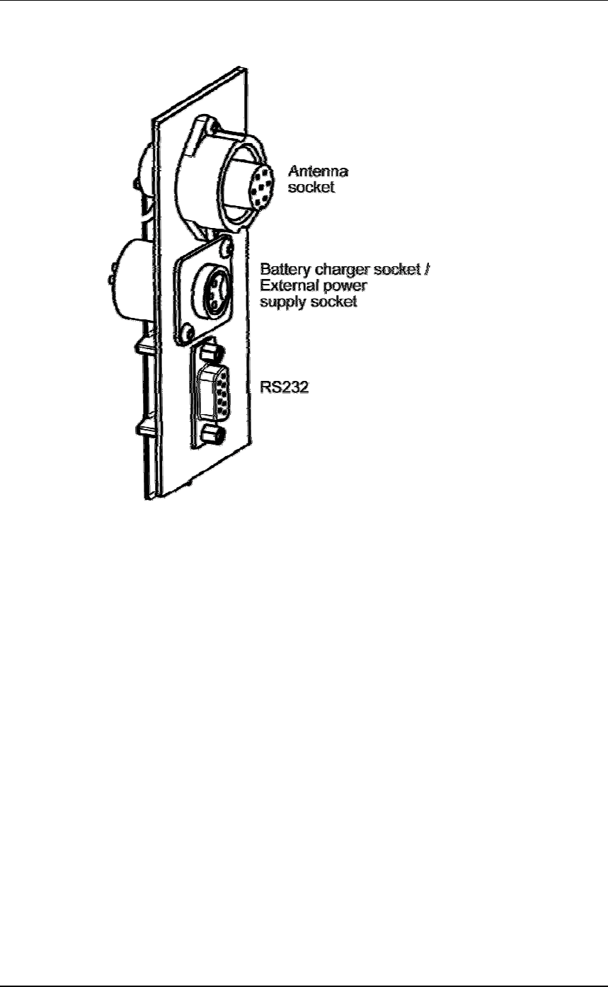
Connect the Electronic Controller to a computer
Procedure
1. Ensure the Electronic Controller is turned off.
2. Using the supplied serial cable, connect the computer and the
Electronic Controller.
d. Connect one end of the serial cable into a COM port on your
computer.
If required, use the supplied DB9 to USB adapter to connect
to the USB port on the computer.
e. Connect the other end into the COM port on the Electronic
Controller
3. Turn the dial to ON or Memory.
The Electronic Controller beeps twice.

3E0680 SmartReader BR Series 3E0680
Page 29
Investigating SmartReader read range issues
If the EID tag read range on your SmartReader installation is not
adequate, check the following:
•The SmartReader is turned on and connected to the Antenna
Panel.
•The EID tag is functional and is in the correct orientation for
testing.
•The Battery Charger is disconnected from the SmartReader.
•The battery charge level indicator shows two or more bars.
Re-test the read range by passing a small group of animals through the
animal handler and reading their Electronic ID tags. If the
SmartReader read range is still not adequate, complete the advanced
testing and contact your Gallagher representative, see Advanced EID
tagreadrangetes(p 30)ting.
Accessing and exiting Setup mode
To swap the SmartReader from SetupmodetoOperationalmode(or
the reverse), complete the following steps:
1. Turn the SmartReader on.
2. Press and hold the Volume button.
3. Turn the SmartReader off.
When you turn the SmartReader back on again the SmartReader will
have swapped to the other mode.
Note: Prior to use, ensure the Electronic Controller volume is on.

3E0680 3E0680 SmartReader BR Series
Page 30
Advanced Electronic ID tag read range
testing
If an adequate EID Tag read range is not achieved during the initial
testing, use the following advanced testing procedures.
Install the Configurator software utility prior to starting the advanced
Electronic ID tag read range testing.
The Configurator software utility is automatically installed with the
MyScale Pro software.
You will need the following items at the animal handler:
•a Laptop computer with either a serial (DB9) or USB port
•a Serial cable (supplied)
•the Serial to USB cable - if using the USB port (supplied).
3E0680 SmartReader BR Series 3E0680
Page 31
Start the Diagnostics Wizard
1. Connect the SmartReader to a computer. See Connect the
Electronic Controller to a computer (p 28).
2. Turn the Electronic Controller to ON or Memory.
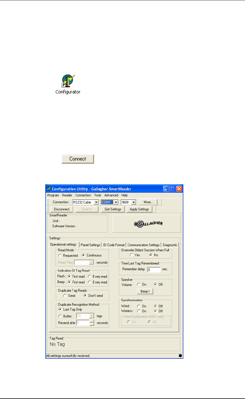
3. Open the Configurator software.
•Double-click on the Configurator icon on the desktop.
OR
a. ClickontheWindowsStart button.
b. Select All Programs (Windows XP) or Programs
(Windows 2000).
c. Select MyScale.
d. Click on SmartReader Configurator.
4. Click .
The current settings for the connected Electronic Controller are
displayed in the lower part of the screen.
3E0680 3E0680 SmartReader BR Series
Page 32
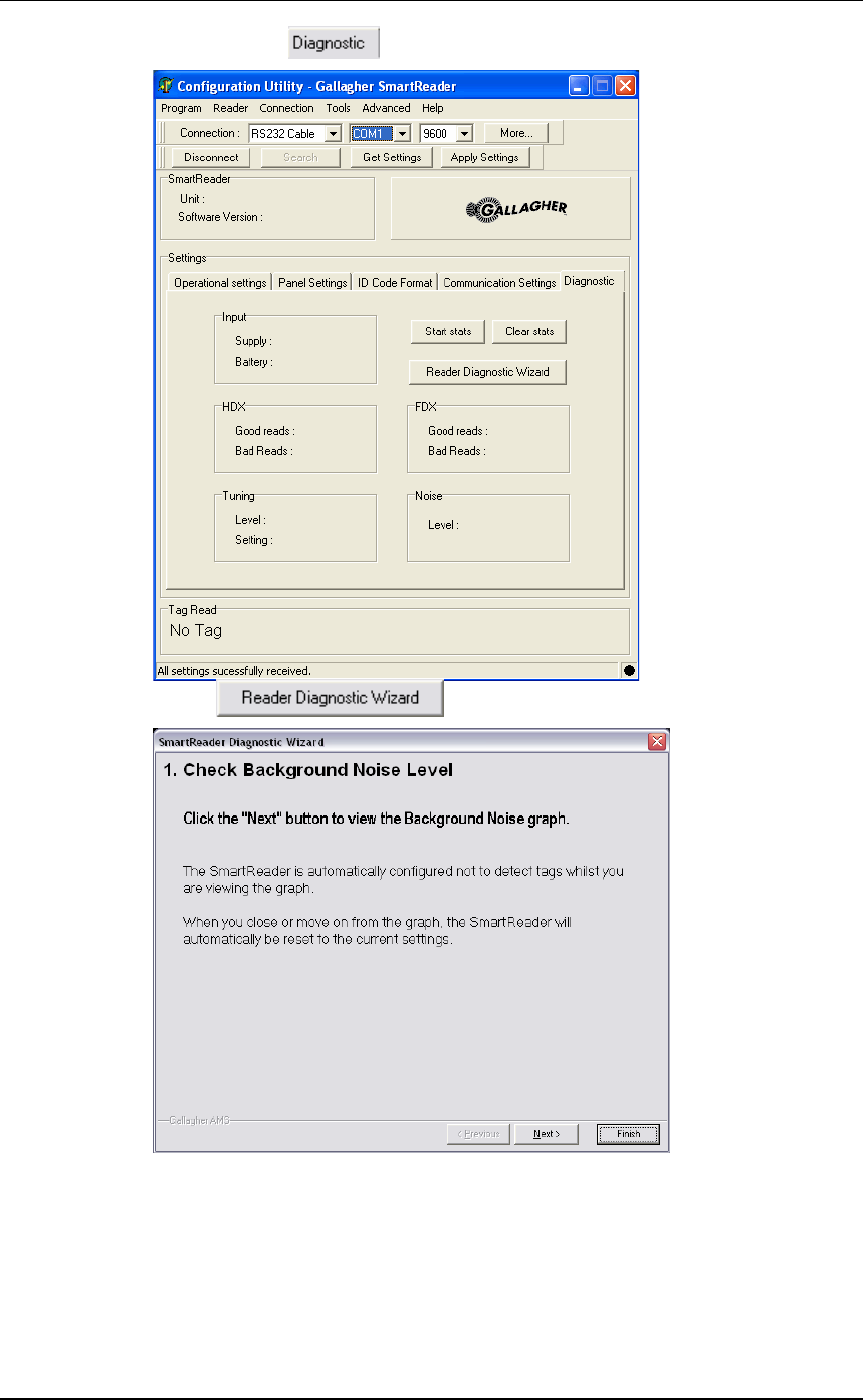
5. Clickonthe tab. The following screen displays:
6. Click . The following screen displays:
3E0680 SmartReader BR Series 3E0680
Page 33
Assessing the background noise
With this screen displayed, SmartReader “hears” background
electrical noise like that generated by Computers, Mobile Phone,
Electrical generators etc in the frequency band that the EID tags work
in. This background noise can interfere with the reading of the EID
tags.
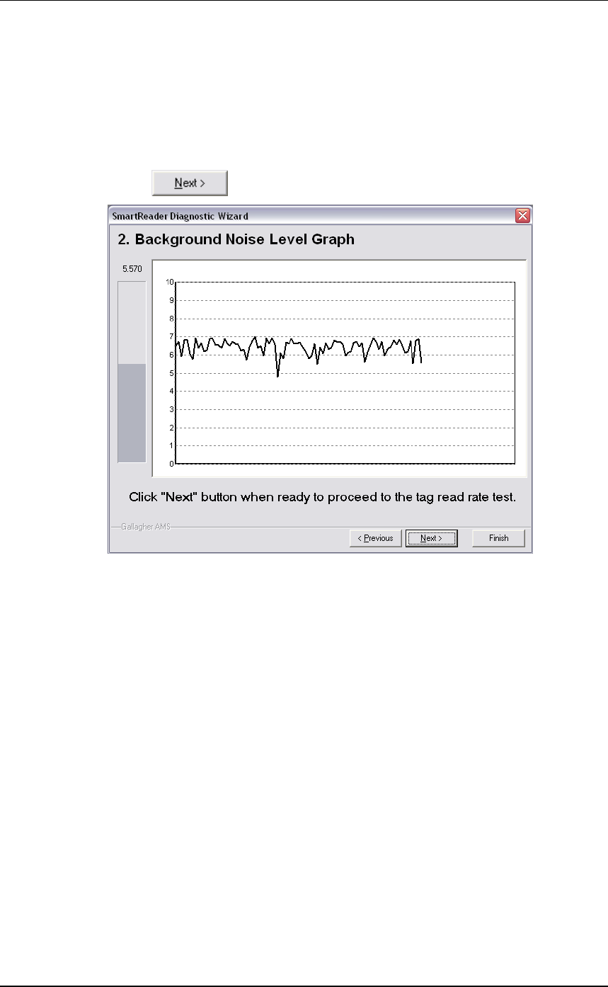
1. Press . The following screen displays:
Note: While this screen displays the SmartReader will not
read EID tags.
The horizontal scale shows approximately 2 minutes viewing of
the background noise.
The vertical scale shows the level of background noise. The
higher up the scale the more background noise and the more likely
theTagreadrangewillbereduced.
2. If the background noise level is high, try turning off sources of
electrical noise and re-test.
3E0680 3E0680 SmartReader BR Series
Page 34
Test read range
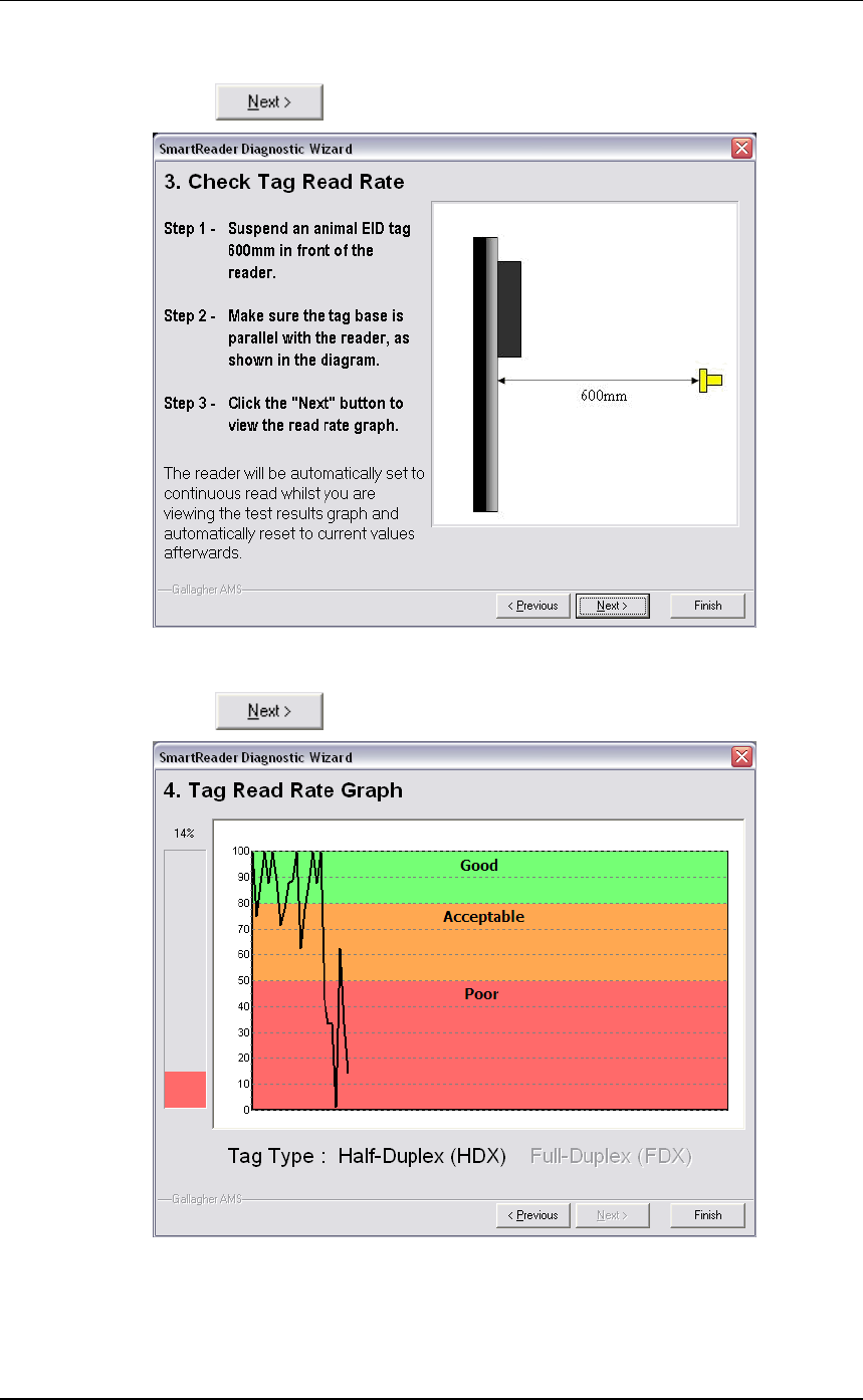
1. Press . The following screen displays:
2. Follow the instructions on the screen to test the EID tag read range
in your animal handler.
3. Press . The following screen displays:
Note: While this screen displays the SmartReader is
automatically set to continuously read.
The type of tag being read is shown at the bottom of the screen.

3E0680 SmartReader BR Series 3E0680
Page 35
4. Alter the mounting location of the Antenna Panel with the aim of
improving the read range.
See Mounting the Panel (p 20).
Note: Once you have finished using the Configurator ensure you click on the
disconnect button in the Configurator program prior to unplugging the
cable. This ensures the data transmission returns to the correct state.
Testing with live animals
1. Pass a small group of animals through the animal handler.
2. Did the SmartReader read all the tags?
•If yes, the SmartReader is operational.
•If no, contact your Gallagher representative for further
information.

3E0680 3E0680 SmartReader BR Series
Page 36
Installing multiple SmartReaders
When multiple SmartReaders are installed in close proximity,
additional set up is required to ensure all Electronic ID tags are read
correctly.
Each SmartReader must be able to communicate with all other
SmartReaders to enable the panel antenna to be switched on and off at
the appropriate times to ensure both Electronic ID tags can be read.
For additional information about tags, see Tag types read (p 3).
•If you have two SmartReaders to install you may use a wireless
installation.
The wired option may also be used. The wired option is the
preferred option for the greatest reliability.
•If you have more than two SmartReaders you must use wired
installation.

3E0680 SmartReader BR Series 3E0680
Page 37
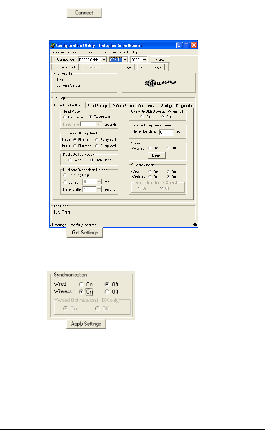
Wireless installation
Note:
•This option is applicable if you are installing two SmartReaders.
OnceyouhaveinstalledbothSmartReaders,youneedtochangethe
following settings in the Electronic Controller via the Configurator
program on your computer.
Procedure
1. Connect the SmartReader to a computer. See Connect the
Electronic Controller to a computer (p 28).
2. Turn the Electronic Controller to ON or Memory.
3. Open the Configurator software.
•Double-click on the Configurator icon on the desktop.
OR
a. ClickontheWindowsStart button.
b. Select All Programs (Windows XP) or Programs
(Windows 2000).
c. Select MyScale.
d. Click on SmartReader Configurator.
3E0680 3E0680 SmartReader BR Series
Page 38
4. Click .
The current settings for the connected Electronic Controller are
displayed in the lower part of the screen.
5. Click .
The Electronic Controller current settings are transferred to the
Configurator and displayed.
6. Set the Synchronisation - Wireless option to On.
7. Click to copy the changes down to the Electronic
Controller.
8. Repeat for the second SmartReader.

3E0680 SmartReader BR Series 3E0680
Page 39
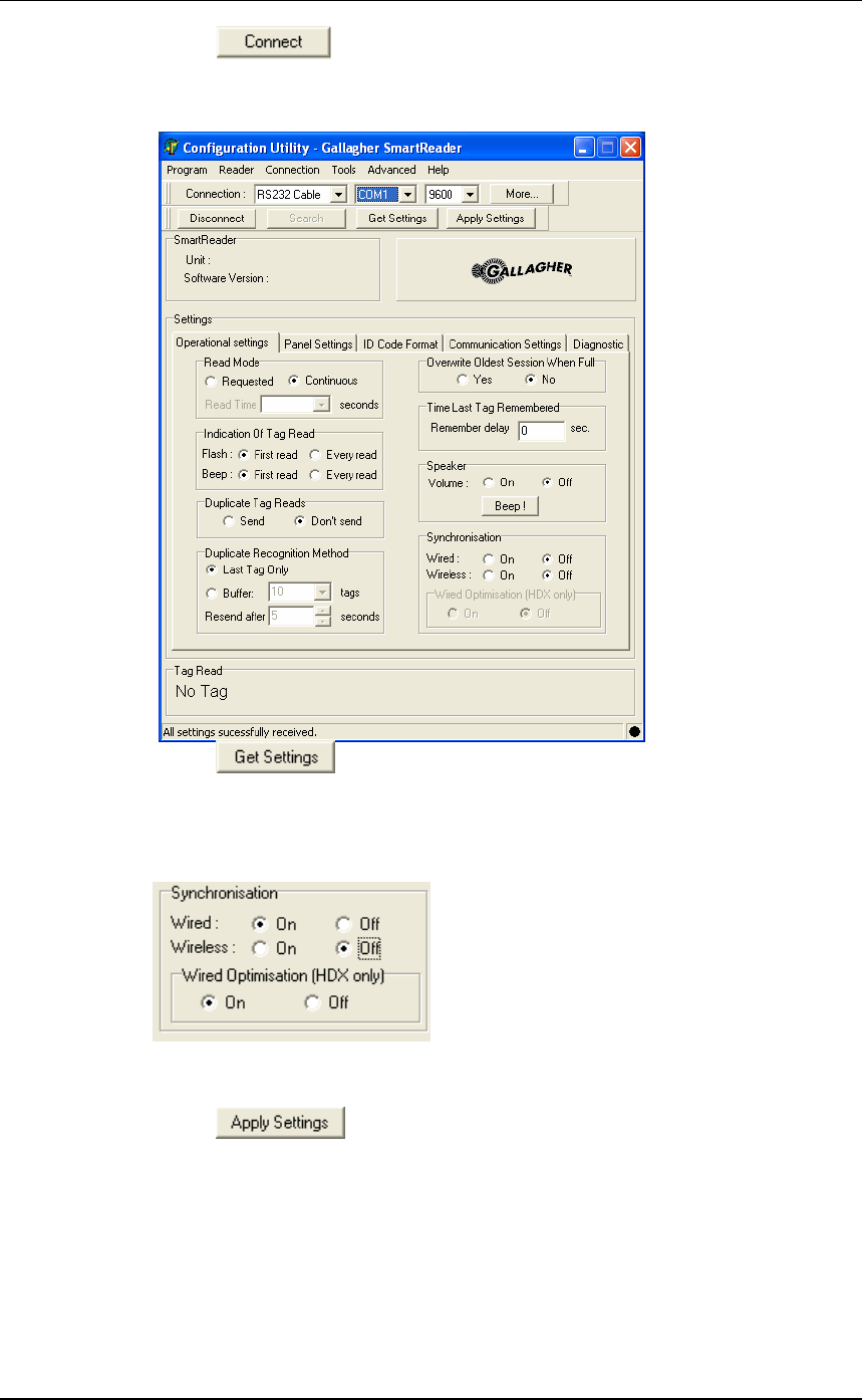
Wired installation
Note:
•Applicable if you are installing three or more SmartReaders.
•Applicable for two SmartReader installations where greater
reliability is required and it is practical to run the required cables.
Once you have installed the SmartReaders, you need to change the
following settings in the Electronic Controller via the Configurator
program on your computer.
Procedure
1. Connect the SmartReader to a computer. See Connect the
Electronic Controller to a computer (p 28).
2. Turn the Electronic Controller to ON or Memory.
3. Open the Configurator software.
•Double-click on the Configurator icon on the desktop.
OR
a. ClickontheWindowsStart button.
b. Select All Programs (Windows XP) or Programs
(Windows 2000).
c. Select MyScale.
d. Click on SmartReader Configurator.
3E0680 3E0680 SmartReader BR Series
Page 40
4. Click .
The current settings for the connected Electronic Controller are
displayed in the lower part of the screen.
5. Click .
The Electronic Controller current settings are transferred to the
Configurator and displayed.
6. Set the Synchronisation - Wired option to On.
7. If you are only reading HDX (Half Duplex) Electronic ID tags, set
the Wired Optimisation (HDX) only option to On.
8. Click to copy the changes down to the Electronic
Controller.
9. Repeat for all other SmartReaders.
3E0680 SmartReader BR Series 3E0680
Page 41
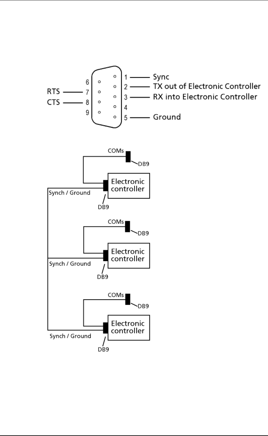
Cabling requirements for connecting
SmartReaders
During the wired installation you need to connect all SmartReaders
together with a cable with the following pin outs:
This cable in not supplied by Gallagher - you are expected to have a
custom cable made to suit the individual installation.
The extra COM connectors enable you to alter the settings of each
Electronic Controller.
Create one for every Electronic Controller you have. This enables you
to easily set up and communicate with all SmartReaders.