Gallagher Group G031404 Controller BR Series Reader User Manual 3E0680 SmartReader BR Series
Gallagher Group Ltd Controller BR Series Reader 3E0680 SmartReader BR Series
Contents
Part 4
3E0680 3E0680 SmartReader BR Series
Page 66
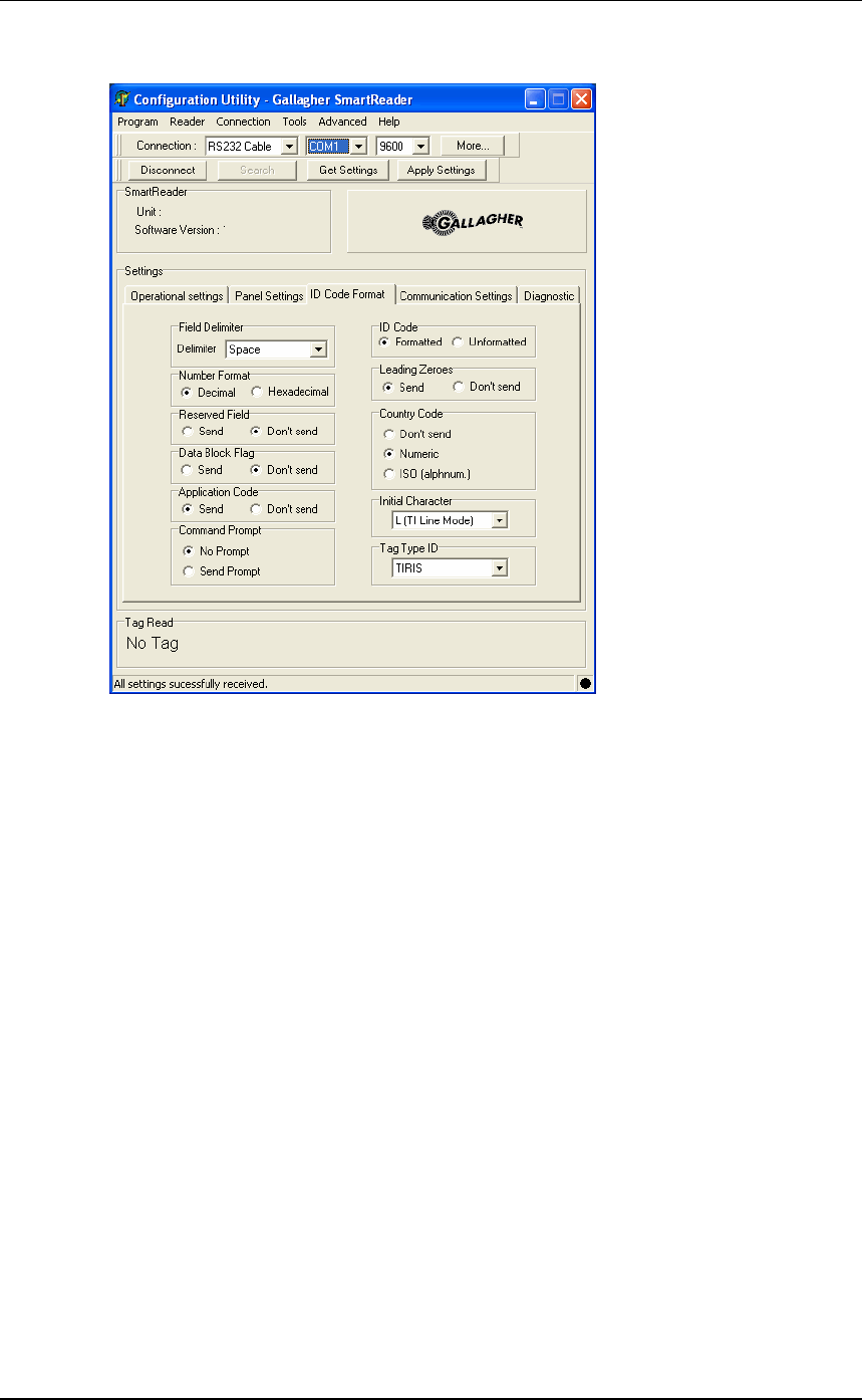
ID Code Format
This screen determines what parts of the captured data are sent out the
Electronic Controller COM port.
The full data (as defined by the ISO 11784 standard) is saved to
internal memory (BR Series only). MyScale Pro transfers all captured
Electronic ID tag information to the connected computer when the
session is transferred.
Both animal and non-animal tags can be processed as defined in the
ISO standard.
Field delimiter
This option sets the field delimiter of the sent data. Used in
conjunction with the ID Code field.
Number format
This option sets the number format the captured data is sent out the
COM port, either Decimal or Hexadecimal.
Reserved field
This option determines whether the Reserved field data is included
in the sent data. Unused in the current standard.
Data block flag
This option determines whether the Data block flag is included in
the sent data.

3E0680 SmartReader BR Series 3E0680
Page 67
Application code
This option determines whether the Application code is included in
the sent data. Applies to non animal Electronic ID tags only.
Command Prompt
This option determines whether a Command prompt (>) is sent after to
sending the data.
ID Code
This option sets whether the data is sent out as formated or un-
formated data.
IftheIDCodeissentoutasFormatted the character defined in the
Field delimited option is inserted between the blocks of data.
Leading zeros
This option determines whether the Leading zeros are included in
the sent data.
Country code
This option determines whether the Country code is included in the
sent data and if so, what format is used. Applies to animal Electronic
ID tags only.
Numeric - a three digit numeric country code is included in the data
string sent out.
ISO (alphnum) - a three digit alphanumeric country code is included
in the data string sent out.
Initial character
This option determines the initial character of the data. Used in
conjunction with the Tag Type ID field.
Tag type ID
This option determines the Tag type ID used to identify the beginning
of the data. Used in conjunction with the Initial character field.
3E0680 3E0680 SmartReader BR Series
Page 68
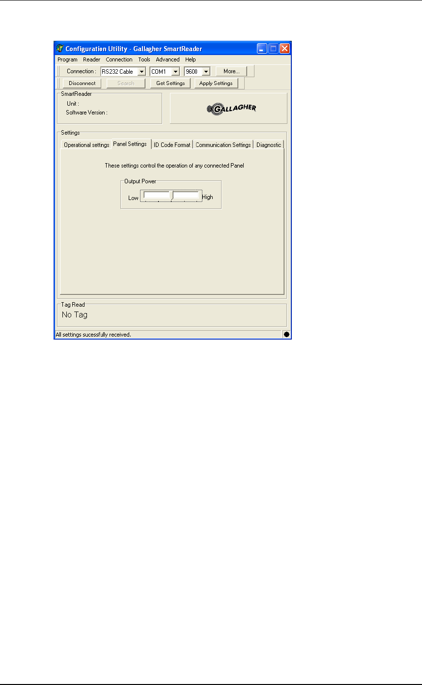
Panel Settings
Output Power
This screen enables you to control the output power level of the
connected Antenna Panel.
The higher the power setting, the more current is drawn from the
batteries.
Note: You must use the highest power setting if you are reading
FDX tags.
If you have multiple Electronic Controller installed on the site AND
are only reading HDX tags you may reduce the power setting. This
will minimise the interference between Electronic Controller and
extend the battery life.
3E0680 SmartReader BR Series 3E0680
Page 69
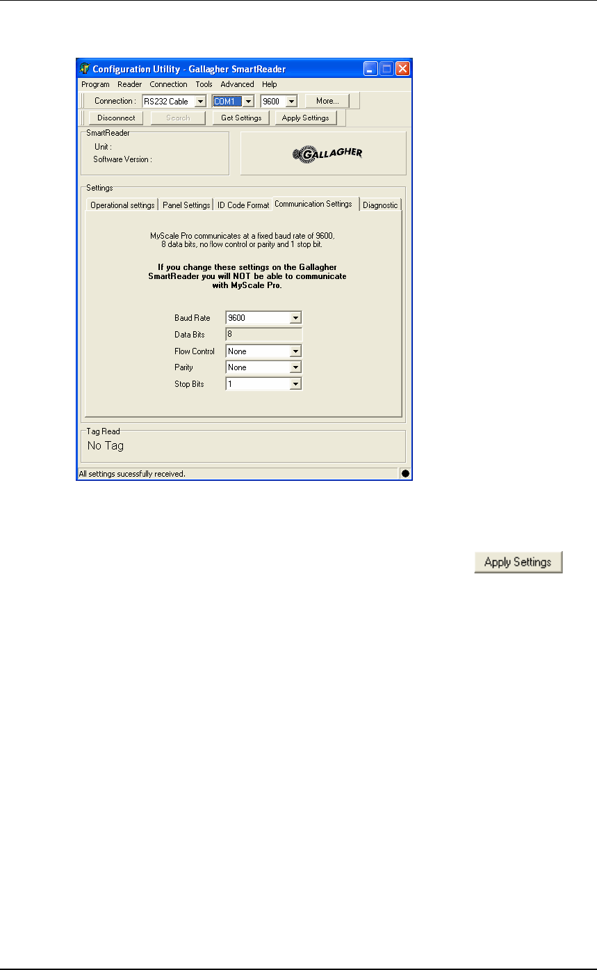
Communication Settings
This screen sets up the connection between a Electronic Controller
and a computer (datalogger, Scale etc) via RS232 or Bluetooth.
Once altered, these settings are saved to the PC only. To transfer the
alterations to the Electronic Controller you must click .
Note: Changing these settings, from the defaults, will cause the
communication between the Electronic Controller and MyScale Pro to
fail.
Baud rate
This option sets the Baud rate of the connection. The default is
9600 bps.
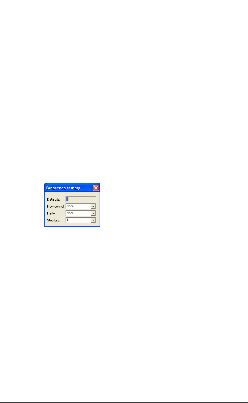
Data bits
Fixed.
Flow control
This option sets the Flow control of the connection. The default is
None.
Parity
This option sets the Parity of the connection. The default is No
parity.
Stop bits
This option sets the Stop bits of the connection. The default is 1.
3E0680 3E0680 SmartReader BR Series
Page 70
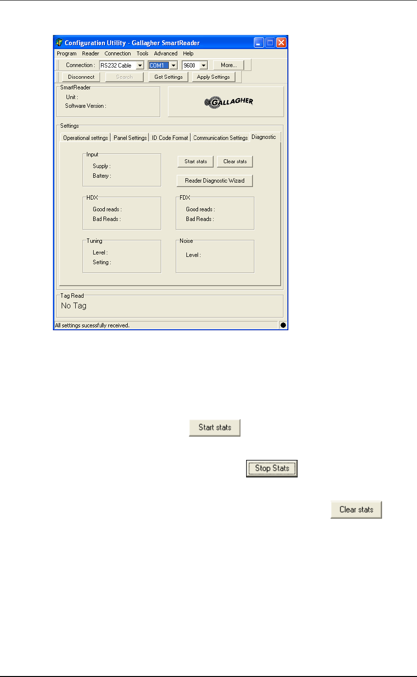
Diagnostics
This screen enables you to:
•view statistics on the functionality of the Electronic Controller and
Antenna Panel, and
•run the diagnostics wizard.
Start Stats
To display statistics, click .
Stop Stats
To stop the display of statistics, click .
Clear Stats
To clear the displayed statistics from the screen, click .
Input
Displays the input supply and battery levels, in volts, for the
connected Electronic Controller.
The input supply indicates the external charger level.
The input battery figure indicates the current internal battery level
(BR Series only).
3E0680 SmartReader BR Series 3E0680
Page 71
HDX (Half Duplex)
Displays the percentage of good and bad HDX tag reads since
statistics display started.
Tuning
This displays the tuning level and setting for the connected Electronic
Controller.
The tuning level indicates how well the Antenna Panel is tuned. The
higher the number the better.
The tuning setting indicates which of the tune settings is currently
used by the Electronic Controller. There are 32 possible settings (0 to
31). If the value is close to either 0 to 31 then there is a risk of not
being able to achieve the optimal tune for the Antenna Panel.
FDX (Full Duplex)
Displays the percentage of good and bad FDX tag reads since
statistics display started.
Noise level
This display the background noise level. Turn off the Antenna Panel
prior to reading this value so you can get a reading of the background
noise in the area of the Antenna Panel.
Turn off the Antenna Panel by changing the read mode to
Requested. See Operational Settings (p 61).
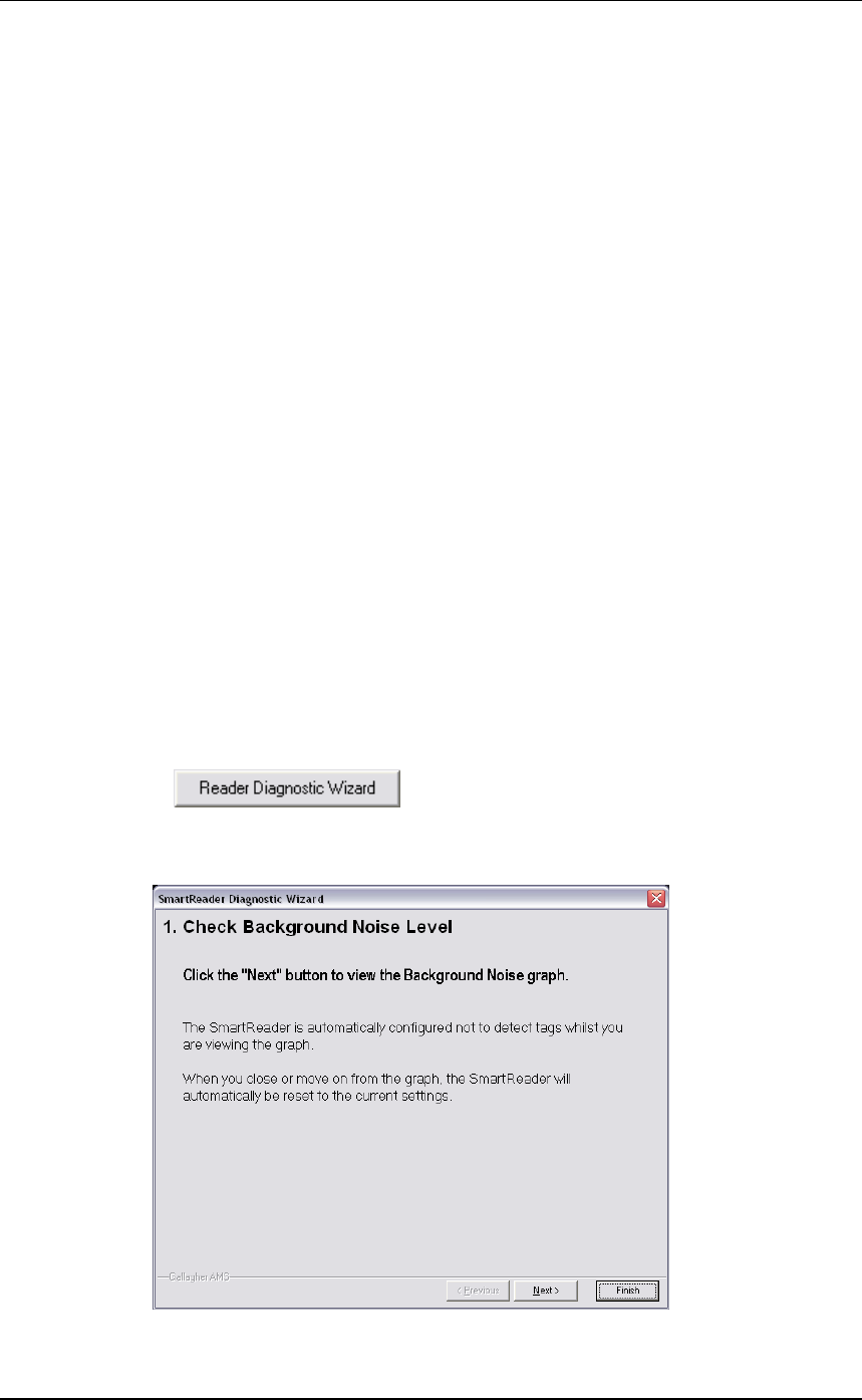
Reader diagnostic wizard
Click andthefollowingscreendisplays:
For more information on using the Reader diagnostic wizard, see
Advanced EID tag read range tes (p 30)ting.

3E0680 3E0680 SmartReader BR Series
Page 72
Menu options
Reader menu
Get settings
See Reader toolbar (p 75).
Apply setting
See Reader toolbar (p 75).
Load factory settings
This option loads the factory default settings into the following
screens:
•Operational settings
•ID Code format
•Communication settings.
Click Apply to transfer setting to Electronic Controller.
Connection menu
Disconnect
For information on this option, see Reader toolbar (p 75).
Settings
For information on these options, see Connection toolbar (p 74).
Search
For information on this option, see Reader toolbar (p 75).
Tools menu
Connection
This option hides or displays the Connection toolbar.
See Connection toolbar (p 74).
Reader
This option hides or displays the Reader toolbar.
See Reader toolbar (p 75).

3E0680 SmartReader BR Series 3E0680
Page 73
Advanced menu
ID code format
Add Delimiter
This option enables you to add an additional delimiter for use in the
Field Limiter field on the ID Code Format (p 66) screen.
1. Select the required type of delimiter (Character or Hexadecimal)
and enter the value.
Note: The Hexadecimal value must be in hexadecimal format.
2. Click OK.
Note: The entered value is checked for validity.
3E0680 3E0680 SmartReader BR Series
Page 74
Toolbars
Connection toolbar
The Connection toolbar displays details of the current connection
between the computer and the Electronic Controller.
The Connection toolbar is hidden or displayed via the Tools menu
(p 72).
Connection
This option indicates the type of connection between the computer and
the Electronic Controller. Options include: RS232 Cable and
Bluetooth.
Port
This option indicates the port on the computer to which the Electronic
Controller is connected.
Baud Rate
This option indicates connection baud rate of the current connection.
More
These options mirror the setting on the Communication Settings (p 69)
screen.

3E0680 SmartReader BR Series 3E0680
Page 75
Reader toolbar
The Reader toolbar is hidden or displayed via the Tools menu (p 72).
Connect button
Click Connect to start communication between the computer and the
Electronic Controller.
Disconnect button
Click Disconnect to stop communication between the computer and
the Electronic Controller.
Search button
Click Search to ask the computer to search for any connected
Electronic Controller. Once an Electronic Controller is found,
communication is automatically started.
Get Settings button
Use this option to get the current settings of the currently connected
Electronic Controller. The Electronic Controller must be connected to
the computer via the serial cable and
This option is also available in the Reader menu (p 72).
Apply setting button
Click Apply to transfer the displayed settings to the Electronic
Controller.
This option is also available in the Reader menu (p 72).

3E0680 3E0680 SmartReader BR Series
Page 76
Accessories
SmartReader Extension Mounting Kit
installation
The Extension Mounting Kit contains:
•1 x Extension cable (4m)
•1xMountingbracket
•2 x metal tek screws
Mount the Antenna Panel
Mount the Antenna Panel as per your SmartReader manual.
Mounting the Electronic Controller
Considerations
•The Extension cable is part of the Antenna Panel circuit so keep
away from large metal surfaces.
•Ensure the Electronic Controller mounting location provides
protection from being knocked or damaged by animals.
•Ensure the Extension cable is run so it can not be damaged or
tripped over.
•Protect the Extension cable from damage from the environment,
animals, people or weather. Avoid mounting the Extension cable
in wet areas.
•**BR Series only** - The Gallagher SmartReader BR Series
Electronic Controller needs to be able to be removed to recharge
the internal batteries.
•The extension cable length is 4 m.
3E0680 SmartReader BR Series 3E0680
Page 77
Procedure
1. Determine the location of the Electronic Controller based on the
above considerations.
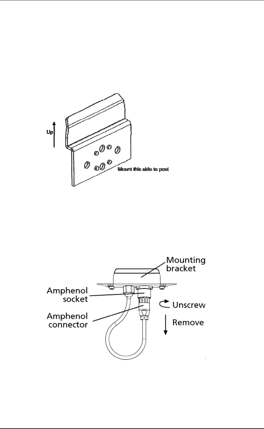
2. Using the supplied metal tek screws attach the mounting bracket
to a solid mounting location using at least two of the holes in the
mounting bracket.
The two sets of two holes allows for installation on horizontal and
vertical pipe work.
3. Run the Extension cable from the Electronic Controller to the
Antenna Panel along the proposed path and temporarily fasten the
cable in place.
4. Ensure the Electronic Controller is turned off.
5. On the Antenna Panel, unscrew the Amphenol connector locking
nut from the Amphenol socket and pull it down to unplug from the
Antenna Panel.
6. Connect the Extension cable to the Amphenol connector and
tighten.
3E0680 3E0680 SmartReader BR Series
Page 78
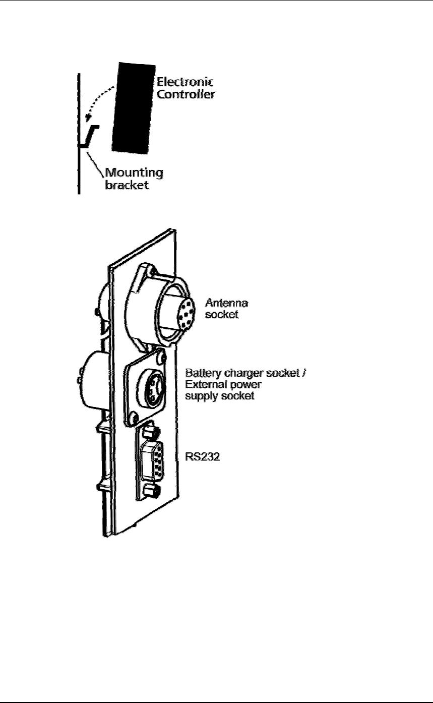
7. Mount the Electronic Controller on the mounting bracket by
grasping the Electronic Controller on both sides and slide the back
handle onto the mounting bracket.
8. Connect the Extension cable to the Amphenol socket on the side
of the Electronic Controller and tighten the locking nut.
9. Once the Extension cable location is finalised, attach the cable
permanently using cable ties.
The SmartReader is now ready to use.
3E0680 SmartReader BR Series 3E0680
Page 79
Specifications
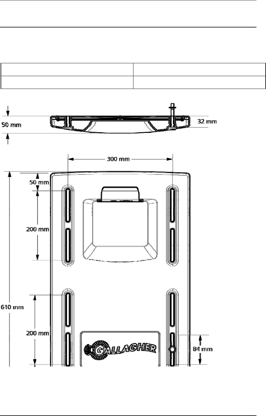
Small Antenna Panels
Small
Small Antenna Panel 3 kg
Dimensions (w x h x d) 400 x 600 x 50 mm