Gantner Electronic GEA1150002A Access Control Terminal, Access Control Terminal with Biometry User Manual GAT Access 6100 Handbuch EN
Gantner Electronic GmbH Access Control Terminal, Access Control Terminal with Biometry GAT Access 6100 Handbuch EN
Contents
- 1. User Manual
- 2. Brochure 6100
- 3. Brochure 6100F
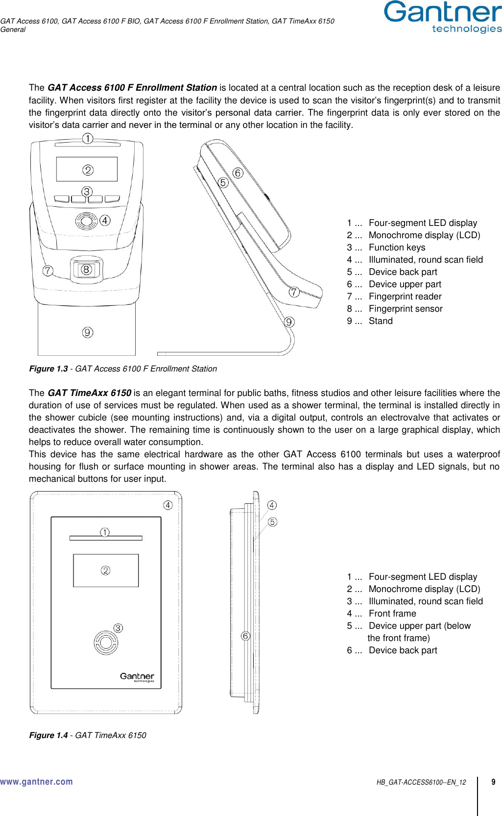
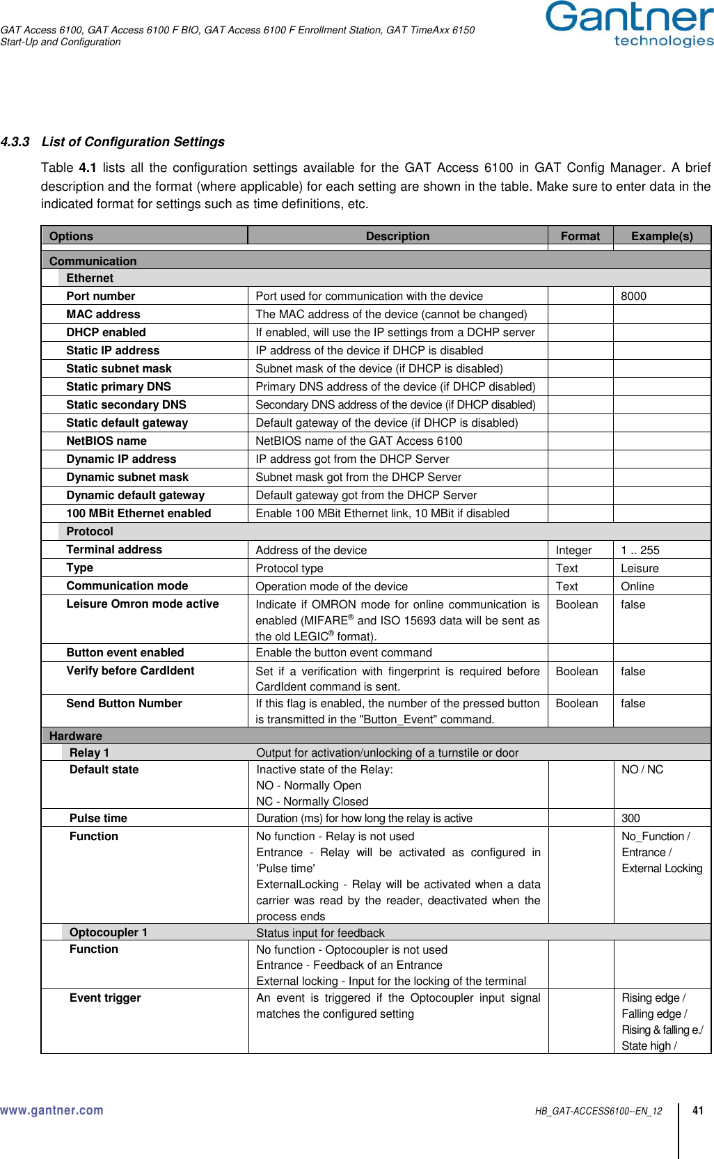
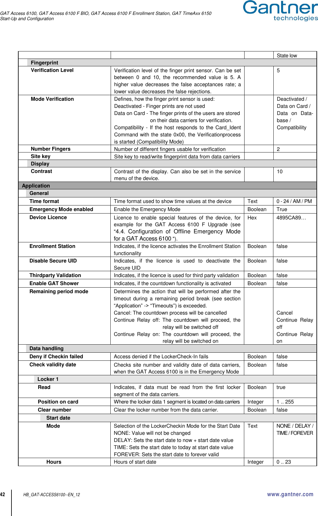
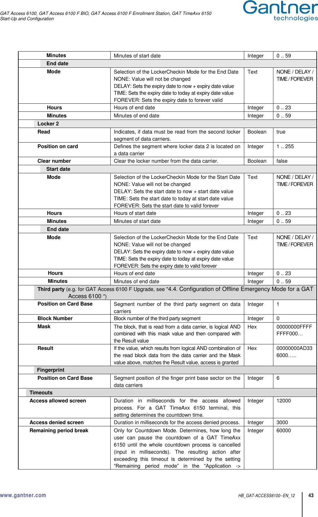
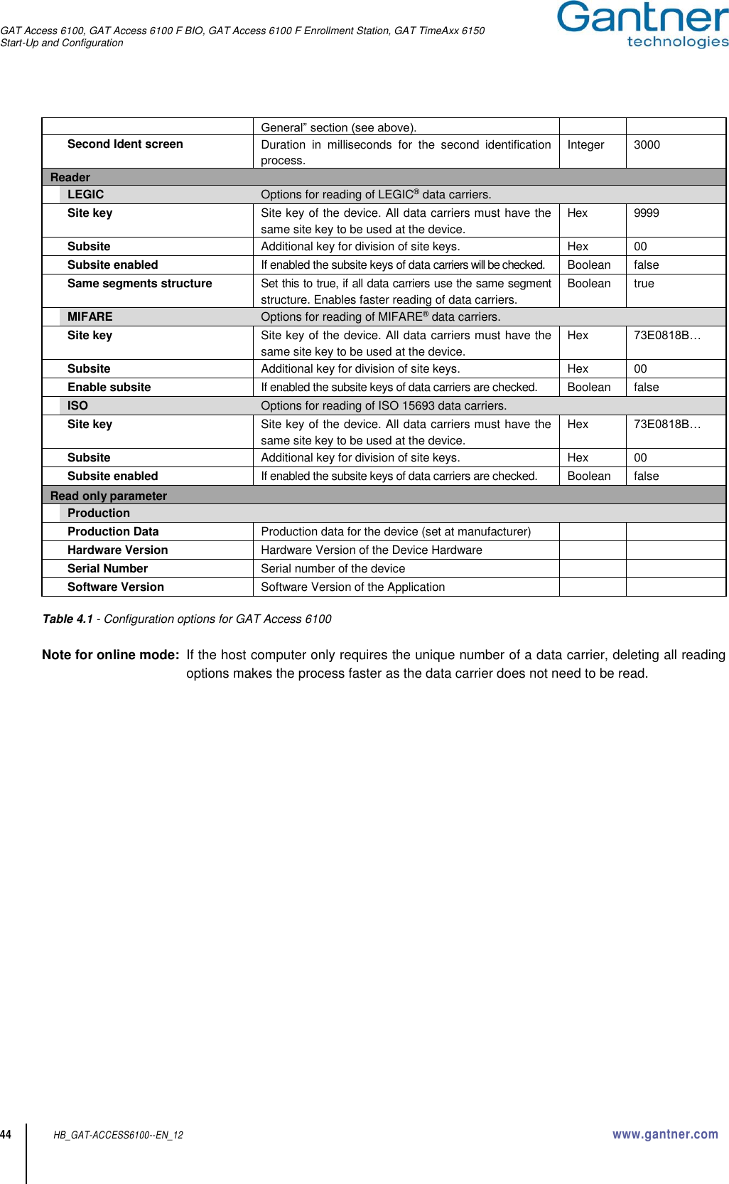
User Manual
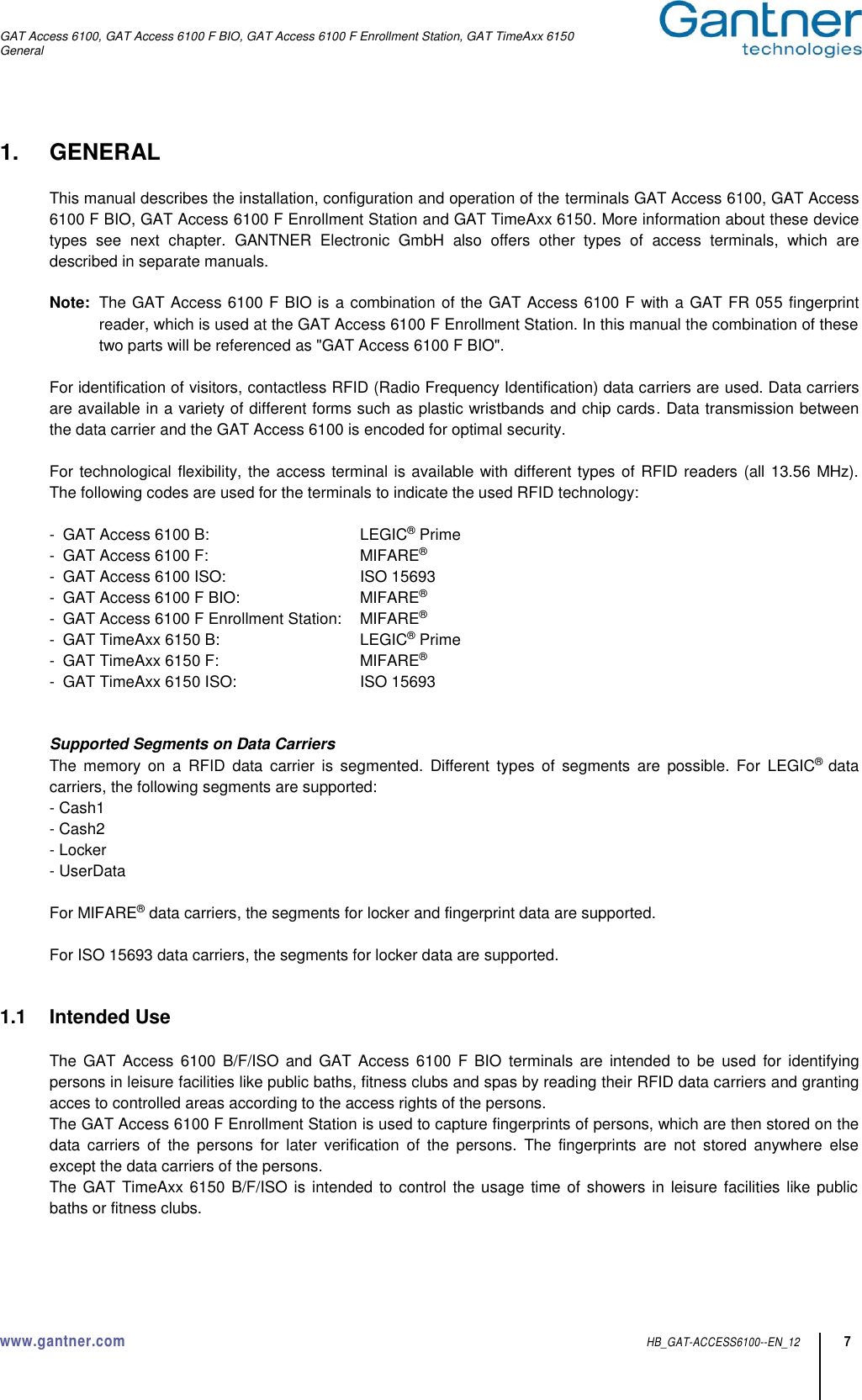
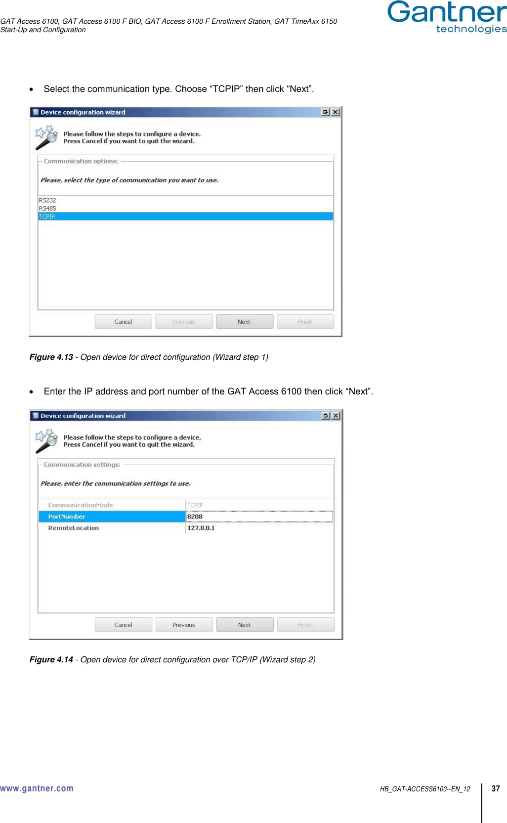
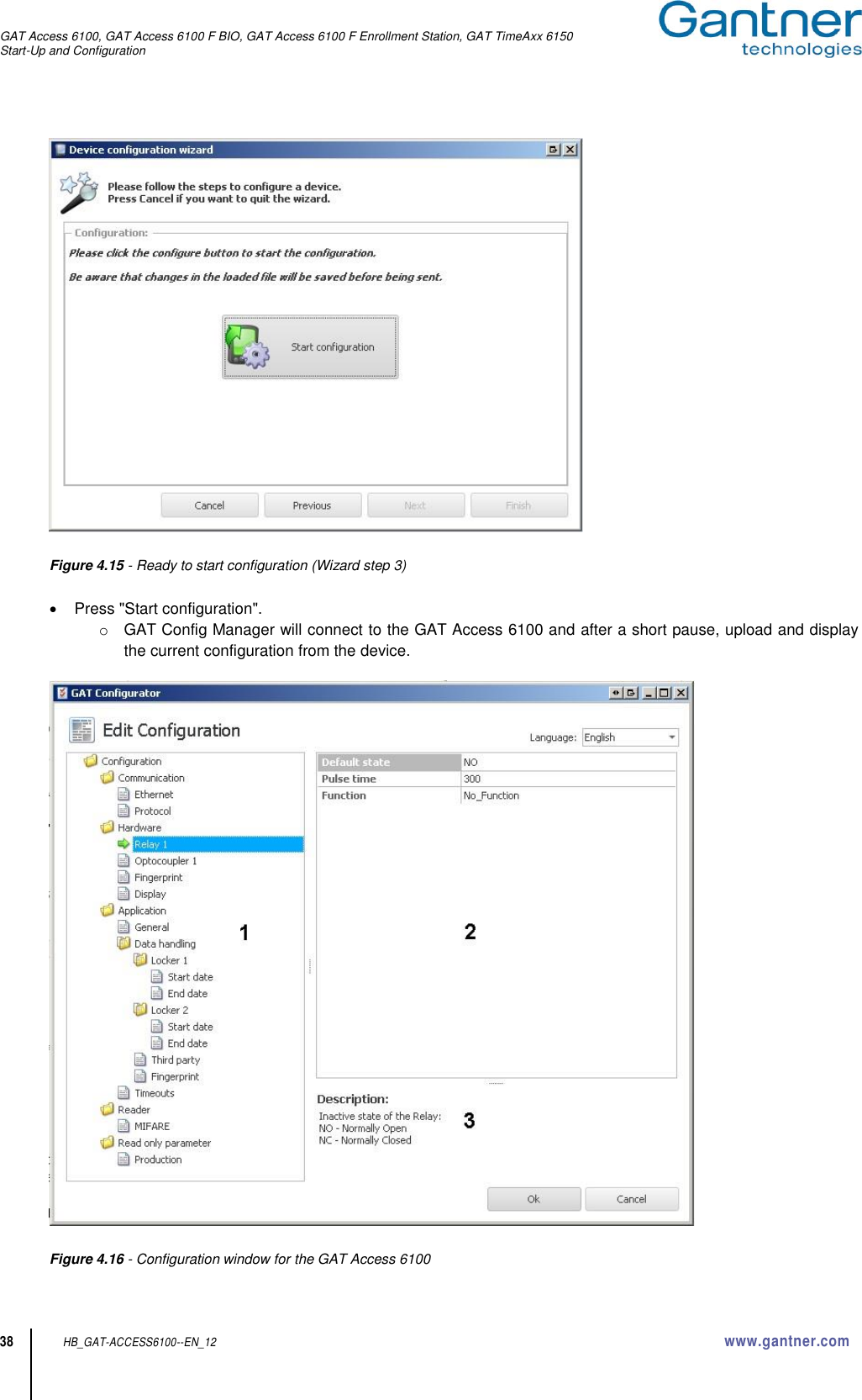
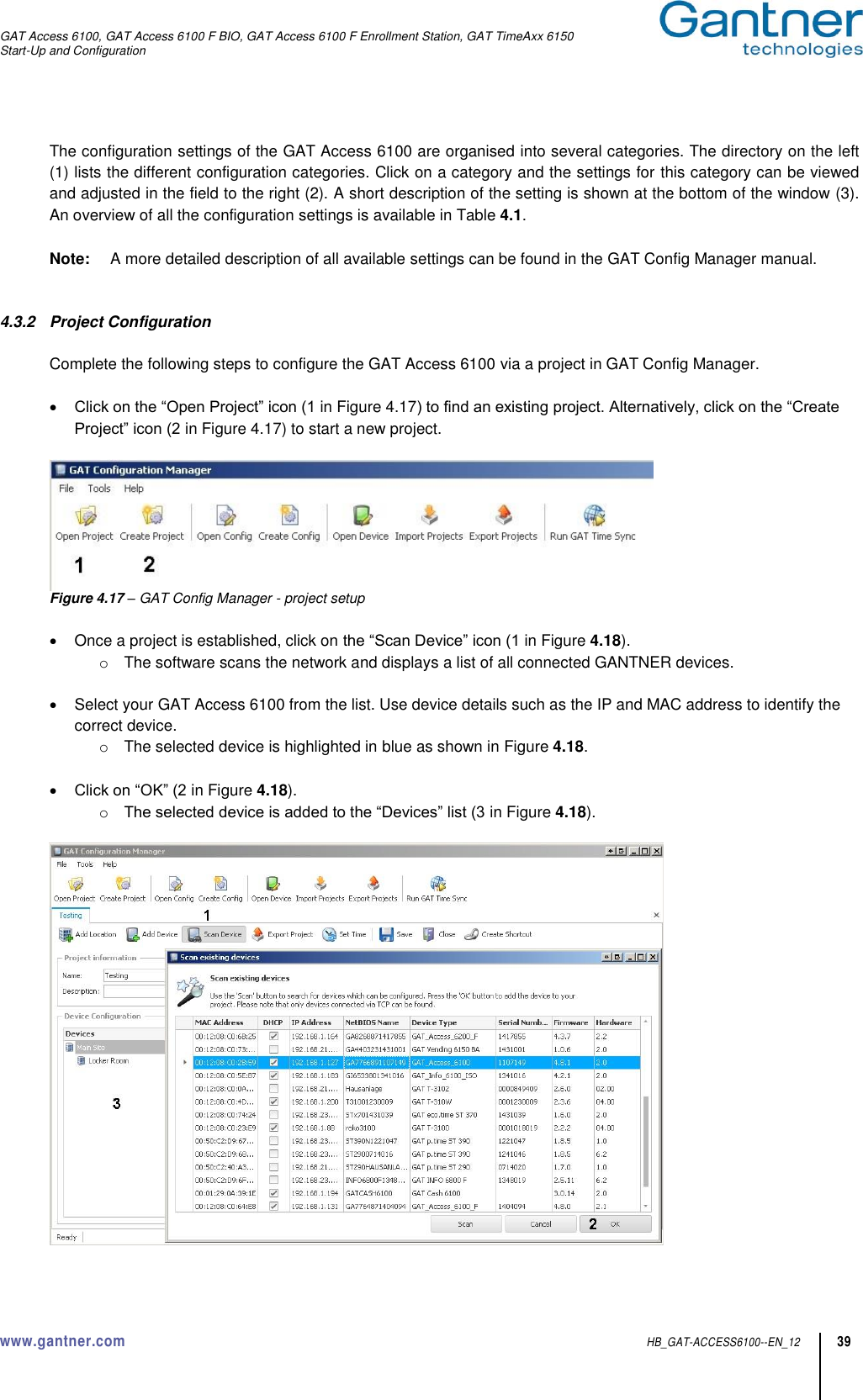
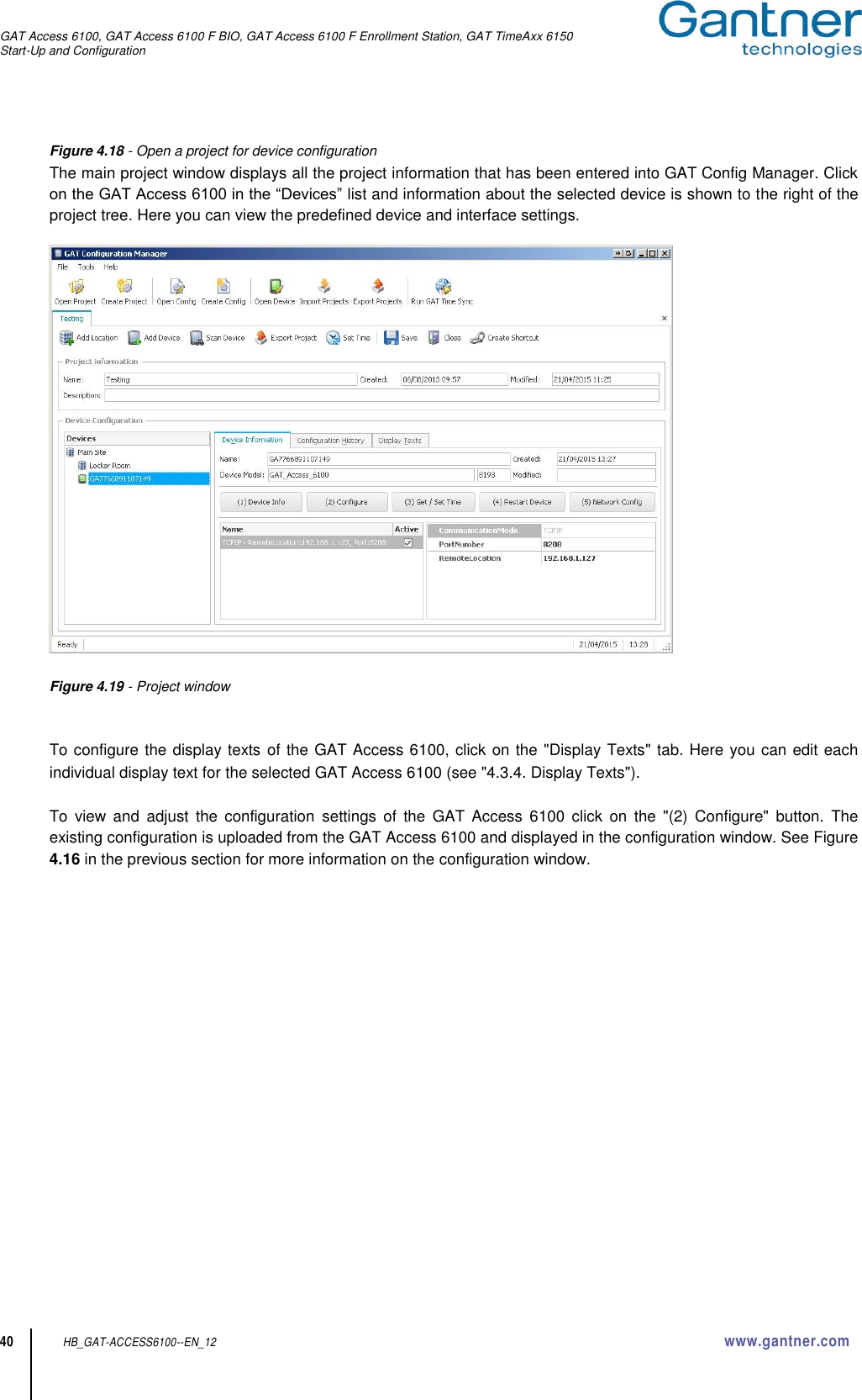
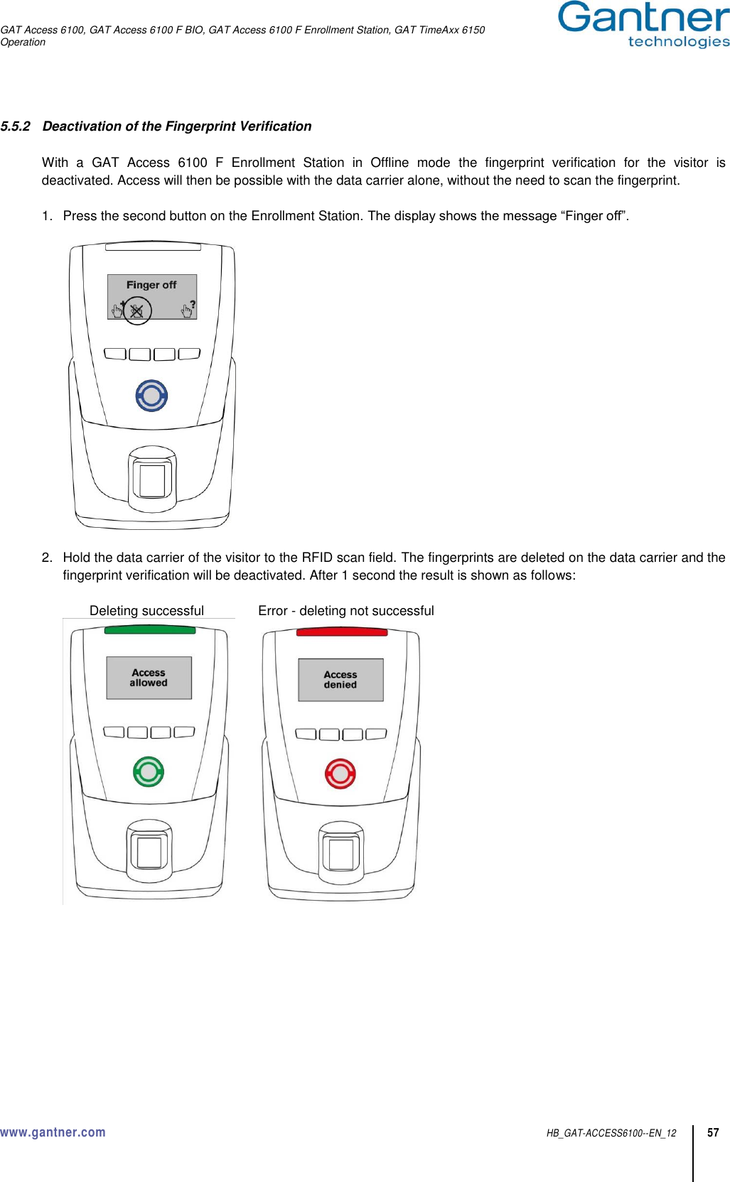
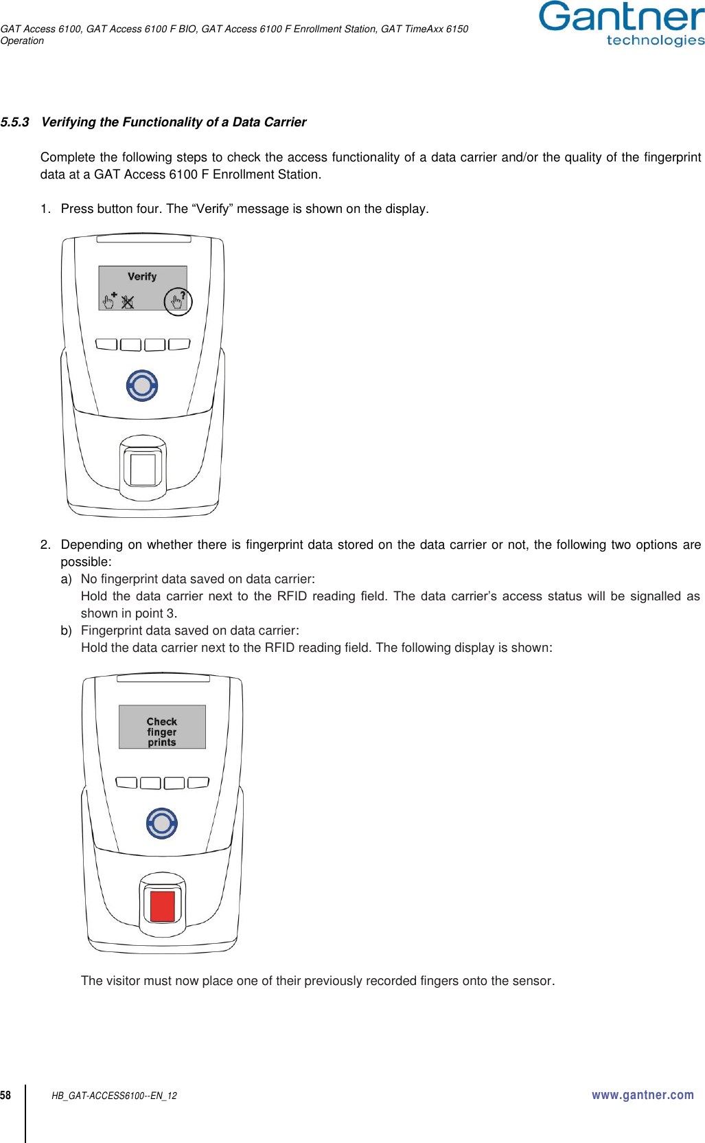
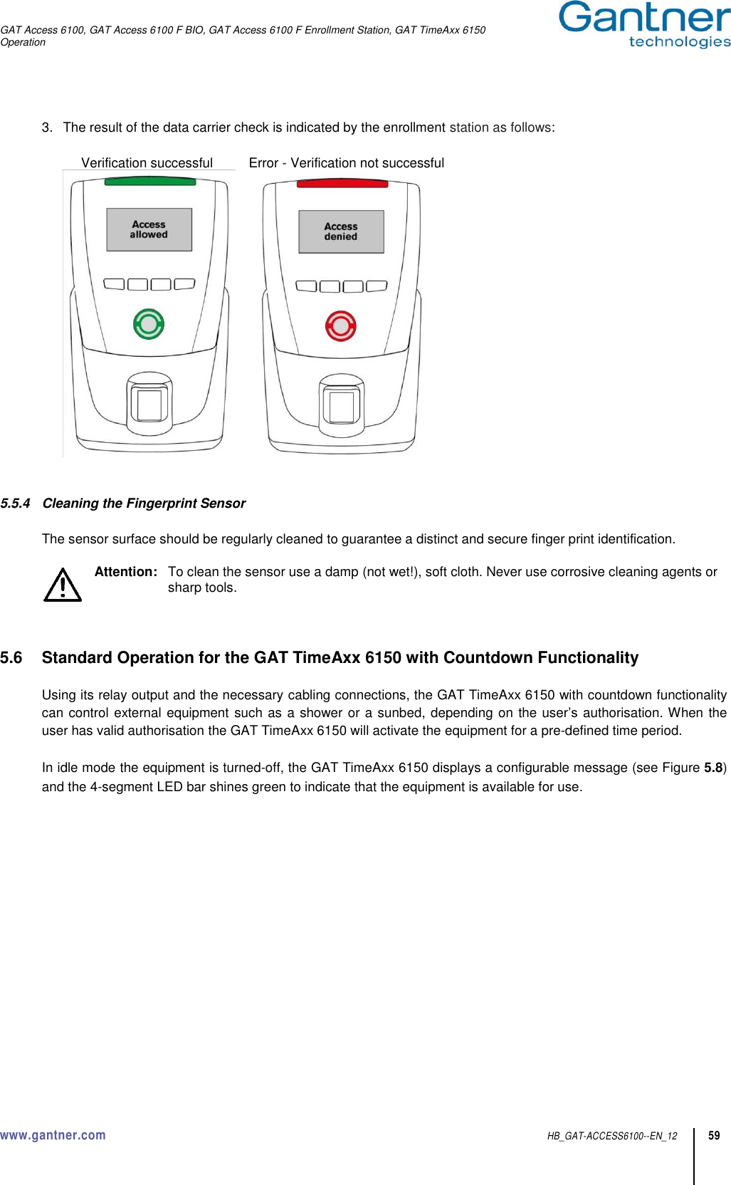
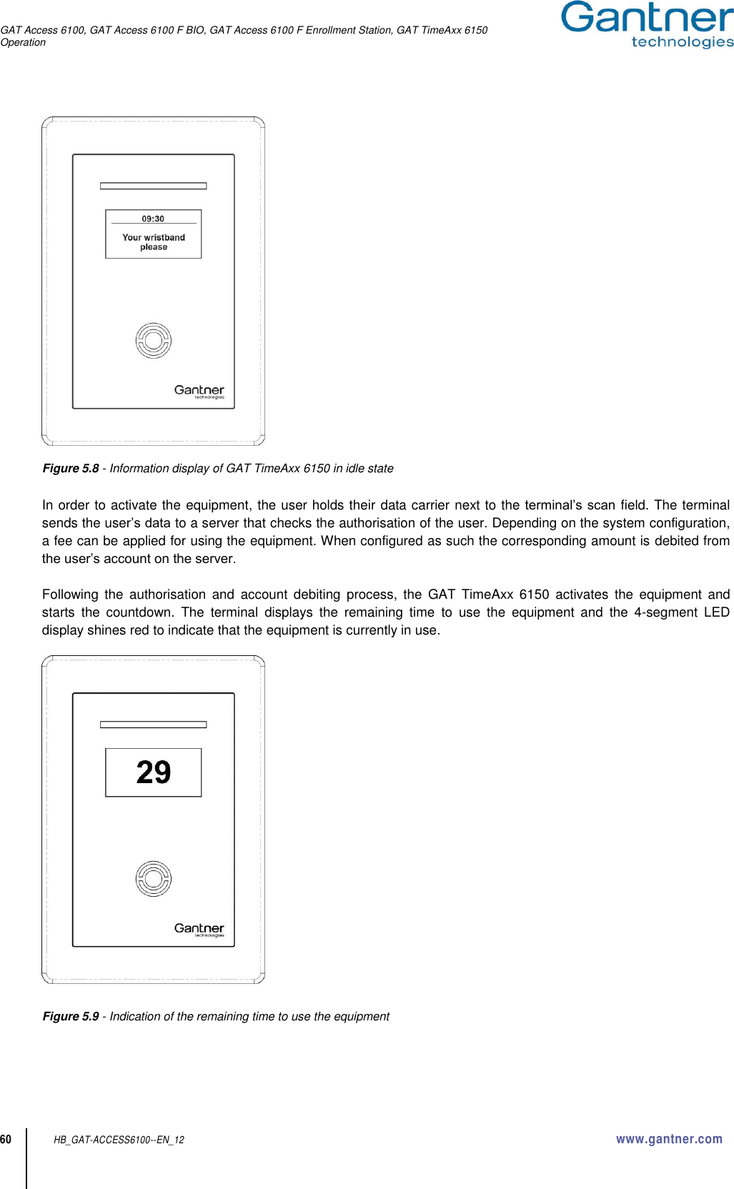
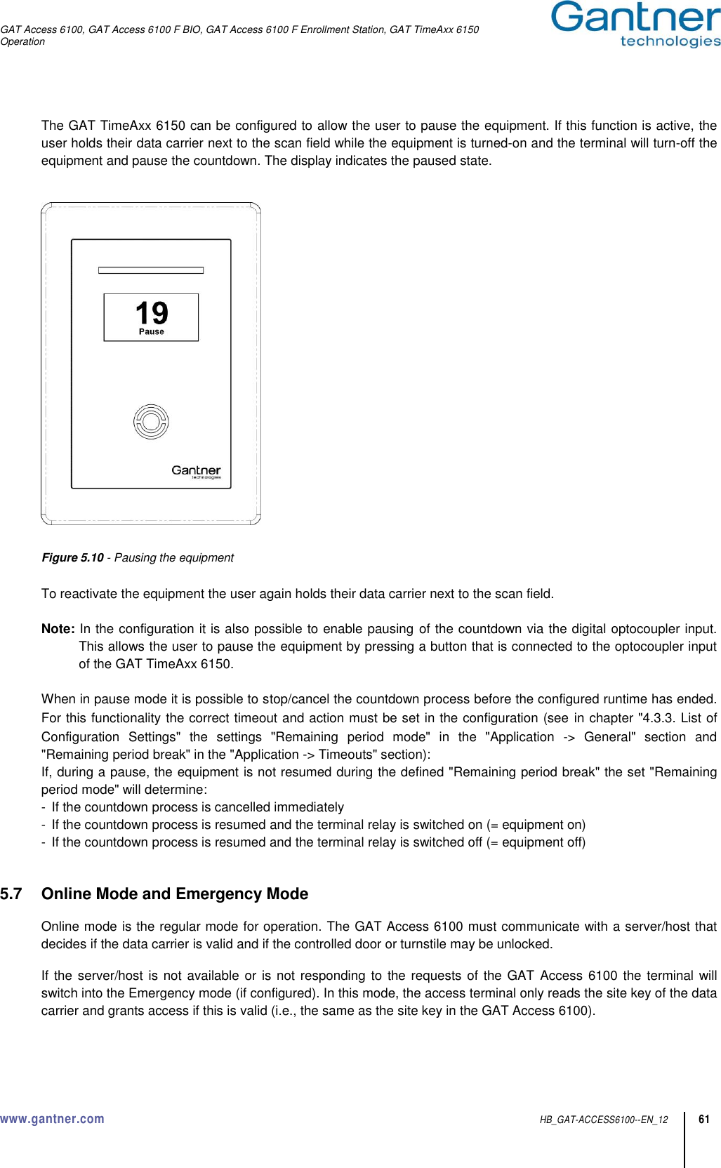
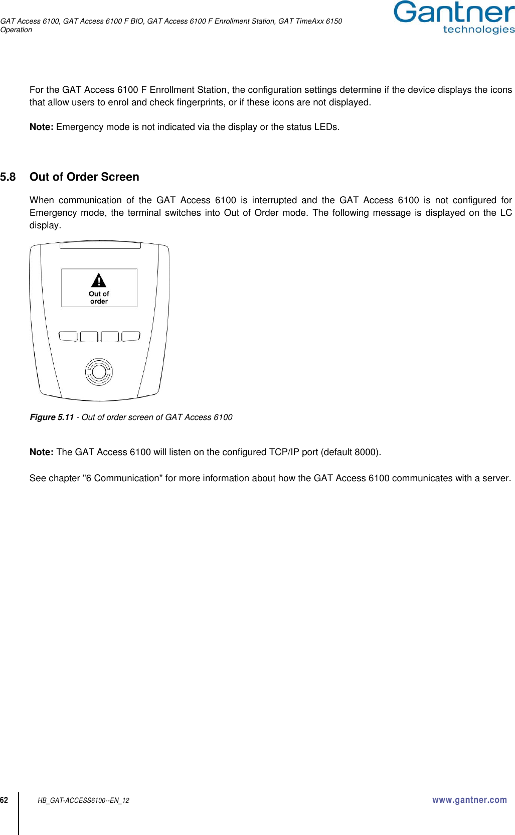
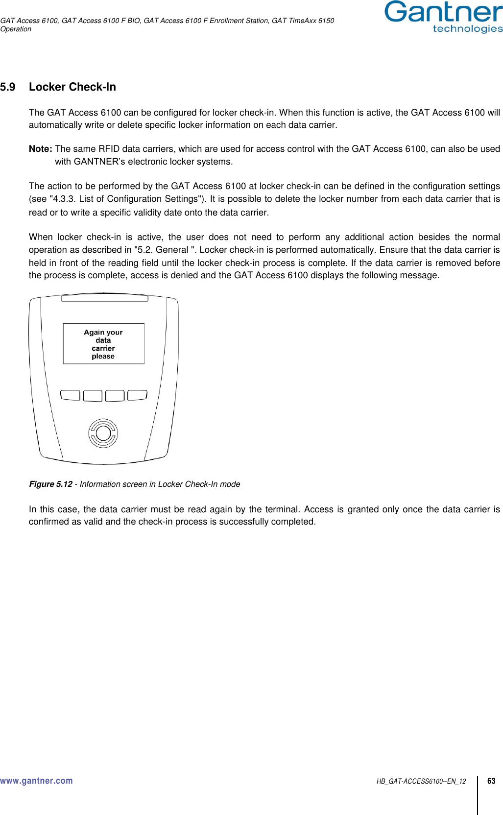
![GAT Access 6100, GAT Access 6100 F BIO, GAT Access 6100 F Enrollment Station, GAT TimeAxx 6150 www.gantner.com HB_GAT-ACCESS6100--EN_12 3 General Warning and Safety Instructions Dear customer, We congratulate you on having selected a product (appliance or software) from GANTNER Electronic GmbH. Our aim is to ensure that our product operates with safety and to your complete satisfaction. To achieve this aim we take this opportunity to familiarize you with the following guidelines: 1. Installation, commissioning, operation and maintenance of the purchased product must be carried out in accordance with the instructions, i.e., in accordance with the technical conditions of operation as described in the corresponding product documentation. 2. Before installation, commissioning, operation or maintenance it is therefore essential that you read the corresponding chapter of this manual and observe its instructions. 3. If there are still some points on which you are not entirely clear, please do not take a chance. All queries can be clarified by your Gantner company representative, or by ringing the GANTNER Electronic GmbH hotline. 4. Where not otherwise specifically documented, the appropriate installation, commissioning, operation and maintenance of the product is the customer’s responsibility. 5. Directly on receipt of the goods, inspect both the packaging and the product itself for any signs of damage. Additionally, check that the delivery is complete and includes all accessories, documentation, auxiliary devices, etc. 6. If the packaging or product has been damaged in transport, or should you suspect that it may have a fault, the product must not be put into service. In this case, contact your Gantner company representative. They will make every effort to resolve the problem as quickly as possible. 7. Installation, commissioning and servicing of our appliances must only be carried out by suitably trained personnel. In particular, electrical connections must only be made by correspondingly qualified specialists. Here, the appropriate installation provisions in accordance with the relevant national Electrical Engineers construction regulations (e.g., ÖVE, [Austrian] VDE, [German]...) must be observed. 8. Where not otherwise stated, installation and maintenance work on our appliances must be carried out when disconnected from the power supply. This applies in particular to appliances that are normally supplied by low-voltage current. 9. It is prohibited to alter the device or to remove protective shields and covers. 10. Do not attempt yourself to repair an appliance after a defect, failure or damage, or to put it back into operation again. In such cases, it is essential you contact either your Gantner company representative or the GANTNER Electronic GmbH hotline. 11. GANTNER Electronic GmbH accepts no responsibility for any injuries or damage caused as a result of improper use. 12. Although every care is taken and we are continuously aiming for improvement, we cannot completely exclude the possibility of errors appearing in our documentation. GANTNER Electronic GmbH therefore accepts no responsibility for the completeness or the accuracy of this manual. The right is reserved to make alterations, and we may carry out alterations at any time without giving prior notice. 13. Should you discover any fault with the product or in its accompanying documentation, or have any suggestions for improvement, you may confidently approach either your Gantner company representative or GANTNER Electronic GmbH directly. 14. We especially look forward to hearing from you if you just want to tell us that everything is functioning perfectly. We wish you a successful experience with our product and look forward to welcoming you again as a customer soon. Contact address / manufacturer: GANTNER Electronic GmbH Montafonerstrasse 8 A - 6780 Schruns/Austria Tel.: +43 5556 73784 - 0 Fax: +43 5556 73784 - 8000 Email: info@gantner.com Website: www.gantner.com](https://usermanual.wiki/Gantner-Electronic/GEA1150002A.User-Manual/User-Guide-2733567-Page-3.png)
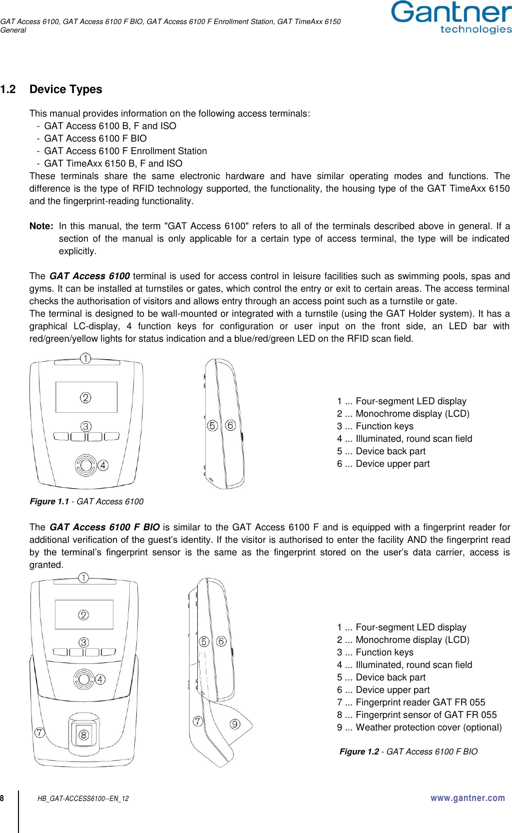


![GAT Access 6100, GAT Access 6100 F BIO, GAT Access 6100 F Enrollment Station, GAT TimeAxx 6150 Technical Data www.gantner.com HB_GAT-ACCESS6100--EN_12 83 9.1.5 FCC and ICES Information Applicable for the following devices: - GAT Access 6100 F - GAT Access 6100 F BIO - GAT Access 6100 F Enrollment Station FCC INFORMATION (U.S.A.) Note: This equipment has been tested and found to comply with the limits for a Class B digital device, pursuant to part 15 of the FCC Rules. These limits are designed to provide reasonable protection against harmful interference in a residential installation. This equipment generates, uses, and can radiate radio frequency energy and, if not installed and used in accordance with the instructions, may cause harmful interference to radio communications. However, there is no guarantee that interference will not occur in a particular installation. If this equipment does cause harmful interference to radio or television reception, which can be determined by turning the equipment off and on, the user is encouraged to try to correct the interference by one or more of the following measures: - Reorient or relocate the receiving antenna. - Increase the separation between the equipment and receiver. - Connect the equipment into an outlet on a circuit different from that of which the receiver is connected. - Consult the dealer or an experienced radio/TV technician for help. FCC Warning Statement [Any] changes or modifications not expressly approved by the party responsible for compliance could void the user's authority to operate the equipment. ICES Statement (Canada) This Class B digital apparatus complies with Canadian ICES-003. Cet appareil numérique de la classe B est conforme à la norme NMB-003 du Canada.](https://usermanual.wiki/Gantner-Electronic/GEA1150002A.User-Manual/User-Guide-2733567-Page-83.png)