Gantner Electronic GEA1150002A Access Control Terminal, Access Control Terminal with Biometry User Manual GAT Access 6100 Handbuch EN
Gantner Electronic GmbH Access Control Terminal, Access Control Terminal with Biometry GAT Access 6100 Handbuch EN
Contents
- 1. User Manual
- 2. Brochure 6100
- 3. Brochure 6100F
User Manual
GAT Access 6100
GAT Access 6100 F BIO
GAT Access 6100 F Enrollment Station
GAT TimeAxx 6150
Entry Control and Shower Control Terminals
Installation, Operation, Configuration
Document version 1.2
GAT Access 6100
GAT Access 6100 F BIO
(GAT Access 6100 F + GAT FR 055)
GAT Access 6100 F
Enrollment Station
GAT TimeAxx 6150

GAT Access 6100, GAT Access 6100 F BIO, GAT Access 6100 F Enrollment Station, GAT TimeAxx 6150
www.gantner.com
HB_GAT-ACCESS6100--EN_12
3
General Warning and Safety Instructions
Dear customer,
We congratulate you on having selected a product (appliance or software) from GANTNER Electronic GmbH. Our aim is to ensure that our
product operates with safety and to your complete satisfaction. To achieve this aim we take this opportunity to familiarize you with the
following guidelines:
1. Installation, commissioning, operation and maintenance of the purchased product must be carried out in accordance with the
instructions, i.e., in accordance with the technical conditions of operation as described in the corresponding product documentation.
2. Before installation, commissioning, operation or maintenance it is therefore essential that you read the corresponding chapter of this
manual and observe its instructions.
3. If there are still some points on which you are not entirely clear, please do not take a chance. All queries can be clarified by your
Gantner company representative, or by ringing the GANTNER Electronic GmbH hotline.
4. Where not otherwise specifically documented, the appropriate installation, commissioning, operation and maintenance of the product
is the customer’s responsibility.
5. Directly on receipt of the goods, inspect both the packaging and the product itself for any signs of damage. Additionally, check that
the delivery is complete and includes all accessories, documentation, auxiliary devices, etc.
6. If the packaging or product has been damaged in transport, or should you suspect that it may have a fault, the product must not be
put into service. In this case, contact your Gantner company representative. They will make every effort to resolve the problem as
quickly as possible.
7. Installation, commissioning and servicing of our appliances must only be carried out by suitably trained personnel. In particular,
electrical connections must only be made by correspondingly qualified specialists. Here, the appropriate installation provisions in accordance
with the relevant national Electrical Engineers construction regulations (e.g., ÖVE, [Austrian] VDE, [German]...) must be observed.
8. Where not otherwise stated, installation and maintenance work on our appliances must be carried out when disconnected from the
power supply. This applies in particular to appliances that are normally supplied by low-voltage current.
9. It is prohibited to alter the device or to remove protective shields and covers.
10. Do not attempt yourself to repair an appliance after a defect, failure or damage, or to put it back into operation again. In such cases,
it is essential you contact either your Gantner company representative or the GANTNER Electronic GmbH hotline.
11. GANTNER Electronic GmbH accepts no responsibility for any injuries or damage caused as a result of improper use.
12. Although every care is taken and we are continuously aiming for improvement, we cannot completely exclude the possibility of errors
appearing in our documentation. GANTNER Electronic GmbH therefore accepts no responsibility for the completeness or the accuracy of
this manual. The right is reserved to make alterations, and we may carry out alterations at any time without giving prior notice.
13. Should you discover any fault with the product or in its accompanying documentation, or have any suggestions for improvement, you
may confidently approach either your Gantner company representative or GANTNER Electronic GmbH directly.
14. We especially look forward to hearing from you if you just want to tell us that everything is functioning perfectly.
We wish you a successful experience with our product and look forward to welcoming you again as a customer soon.
Contact address / manufacturer:
GANTNER Electronic GmbH
Montafonerstrasse 8
A - 6780 Schruns/Austria
Tel.: +43 5556 73784 - 0
Fax: +43 5556 73784 - 8000
Email: info@gantner.com
Website: www.gantner.com
GAT Access 6100, GAT Access 6100 F BIO, GAT Access 6100 F Enrollment Station, GAT TimeAxx 6150
4
HB_GAT-ACCESS6100--EN_12
www.gantner.com
FCC Label
Applicable for the following devices:
- GAT Access 6100 F
- GAT Access 6100 F BIO
- GAT Access 6100 F Enrollment Station
This WEEE symbol on GANTNER products and their packaging indicates that the corresponding material must not be
disposed of with normal household waste. Instead, such marked waste equipment must be disposed of by handing it
over to a designated electronic waste recycling facility. Separating and recycling this waste equipment at the time of
disposal will help to conserve natural resources and ensure that it is recycled in a manner that protects human health and
the environment. Please contact your local authority for details on your nearest electronic waste recycling facility.
Copyright 2015 by GANTNER Electronic GmbH, Schruns (Austria).
Copyrights: Operating instructions, manuals and software are protected by copyright ©. All rights are reserved. Copying,
duplication, translation, installation in any electronic medium or machine-readable form in whole or in part is
prohibited. The sole exception is represented by creation of a back-up copy of software for own use as a
safeguard, so far as this is technically possible and recommended by us. Any infringement will render the party
committing such infringement liable to compensation payment.
Liability: Any claims against the manufacturer based on the hardware or software products described in this manual shall
depend exclusively on the conditions of the guarantee. Any further-reaching claims are excluded, and in particular,
the manufacturer accepts no liability for the completeness or accuracy of the contents of this manual. The right is
reserved to make alterations, and alterations may be made at any time without prior notice being given.
Trademarks: Attention is drawn at this point to the logos and registered trademarks used in this manual.
This device complies with Part 15 of the FCC Rules.
Operation is subject to the following two conditions: (1) this
device must not cause harmful interference, and (2) this
device must accept any interference received, including
interference that may cause undesired operation.

GAT Access 6100, GAT Access 6100 F BIO, GAT Access 6100 F Enrollment Station, GAT TimeAxx 6150
Table of Contents
www.gantner.com
HB_GAT-ACCESS6100--EN_12
5
TABLE OF CONTENTS
1. GENERAL ...................................................................................................................................................... 7
1.1 Intended Use ........................................................................................................................................... 7
1.2 Device Types .......................................................................................................................................... 8
1.3 Standard Operation ............................................................................................................................... 10
1.4 Operating Modes ................................................................................................................................... 10
1.5 Other Devices in the GAT Access 6xxx Series ..................................................................................... 11
1.6 Function Matrix for the GAT Access Devices ....................................................................................... 12
1.7 Special Functions and Options ............................................................................................................. 13
1.7.1 GAT Device Finder Support ........................................................................................................... 13
2. MOUNTING THE GAT ACCESS 6100 TERMINALS .................................................................................. 15
2.1 GAT Access 6100 ................................................................................................................................. 15
2.1.1 Wall Mounting ................................................................................................................................ 15
2.2 GAT Access 6100 F BIO ....................................................................................................................... 17
2.2.1 Wall Mounting ................................................................................................................................ 17
2.3 GAT Access 6100 F Enrollment Station ............................................................................................... 20
2.4 GAT TimeAxx 6150 ............................................................................................................................... 21
2.4.1 Surface Mounting ........................................................................................................................... 21
2.4.2 Flush Mounting .............................................................................................................................. 23
3. ELECTRICAL CONNECTIONS ................................................................................................................... 27
3.1 Power Supply ........................................................................................................................................ 27
3.2 Network ................................................................................................................................................. 28
3.2.1 Ethernet Network ........................................................................................................................... 28
3.3 Connection to Turnstile or Door ............................................................................................................ 29
3.4 Checklist for Final Installation ............................................................................................................... 30
4. START-UP AND CONFIGURATION ........................................................................................................... 31
4.1 Starting the GAT Access 6100 .............................................................................................................. 31
4.2 System Settings .................................................................................................................................... 32
4.2.1 Service Menu of GAT Access 6100 ............................................................................................... 32
4.2.2 Communication Parameters .......................................................................................................... 33
4.2.3 Reader Settings ............................................................................................................................. 34
4.2.4 Date and Time Settings ................................................................................................................. 35
4.2.5 Display Contrast ............................................................................................................................. 35
4.2.6 Restore Factory Settings ............................................................................................................... 35
4.3 Configuration Settings ........................................................................................................................... 36
4.3.1 Direct Configuration ....................................................................................................................... 36
4.3.2 Project Configuration ..................................................................................................................... 39
4.3.3 List of Configuration Settings ......................................................................................................... 41
4.3.4 Display Texts ................................................................................................................................. 45
4.4 Configuration of Offline Emergency Mode for a GAT Access 6100 ..................................................... 46
5. OPERATION ................................................................................................................................................ 49
5.1 Control and Display Elements ............................................................................................................... 49
5.2 General .................................................................................................................................................. 50
5.3 User Operation at a GAT Access 6100 ................................................................................................. 51
5.3.1 Additional Acknowledgment or Selection by the User ................................................................... 52
5.3.2 Problem when Writing to the Data Carrier ..................................................................................... 52
5.4 User Operation at a GAT Access 6100 F BIO ...................................................................................... 53
5.5 User Operation at a GAT Access 6100 F Enrollment Station ............................................................... 53
5.5.1 Enrol Fingerprints at the Enrollment Station .................................................................................. 53
5.5.2 Deactivation of the Fingerprint Verification .................................................................................... 57
5.5.3 Verifying the Functionality of a Data Carrier .................................................................................. 58
5.5.4 Cleaning the Fingerprint Sensor .................................................................................................... 59

GAT Access 6100, GAT Access 6100 F BIO, GAT Access 6100 F Enrollment Station, GAT TimeAxx 6150
Table of Contents
6
HB_GAT-ACCESS6100--EN_12
www.gantner.com
5.6 Standard Operation for the GAT TimeAxx 6150 with Countdown Functionality .................................. 59
5.7 Online Mode and Emergency Mode ..................................................................................................... 61
5.8 Out of Order Screen ............................................................................................................................. 62
5.9 Locker Check-In ................................................................................................................................... 63
5.10 General Open Function (Group Entry) ............................................................................................. 64
5.11 External Release Function................................................................................................................ 64
6. COMMUNICATION ..................................................................................................................................... 65
6.1 Online Mode ......................................................................................................................................... 65
6.2 Emergency Mode ................................................................................................................................. 65
6.3 Out of Operation Mode ......................................................................................................................... 65
7. UPDATING THE GAT ACCESS 6100 ........................................................................................................ 67
7.1 Updating with GAT Config Manager .................................................................................................... 67
8. TROUBLESHOOTING AND FAQ .............................................................................................................. 71
8.1 How can I update the firmware of a GAT Access 6100? ..................................................................... 71
8.2 How do I configure a GAT Access 6100? ............................................................................................ 71
8.2.1 How do I activate service mode? .................................................................................................. 71
8.3 Which TCP/IP ports can be used by a GAT Access 6100? ................................................................. 72
8.4 Which bit rates are used by a GAT Access 6100 for Ethernet and is this configurable? .................... 72
8.5 How can I set the date and time of a GAT Access 6100? ................................................................... 72
8.6 How can I find the IP address of a GAT Access 6100 and change it? ................................................ 72
8.7 How can I find the MAC address of a GAT Access 6100? .................................................................. 73
8.8 Setting IP address when MAC address is not known and IP address of the terminal is 0.0.0.0 ......... 73
8.9 Difference between "Time" and "Delay" in the "Mode" field for Locker Check-In configuration? ........ 73
8.10 Meaning of optocoupler settings "Rising_Edge", "Falling_Edge", "Rising- and Falling Edge"? ....... 74
8.11 How can the reader of a GAT Access 6100 B be authorised for LEGIC®? ...................................... 74
8.12 How can I read or delete the authorisation data of a GAT Access 6100? ....................................... 74
8.13 How can I configure the display texts of a GAT Access 6100? ........................................................ 74
8.14 The relay of the GAT Access 6100 is activated even if the host has denied access. ...................... 75
8.15 Which FUNLINE protocol commands are supported by a GAT Access 6100? ............................... 75
8.16 Why does the GAT Access 6100 deny access with my data carrier in Emergency mode? ............. 75
8.17 What is the maximum start-up current consumption of a GAT Access 6100? ................................. 75
8.18 What are the factory settings of a GAT Access 6100? ..................................................................... 75
8.19 How do I configure a GAT Access 6100 for offline emergency mode? ............................................ 77
8.20 What is the data carrier certificate? .................................................................................................. 77
9. TECHNICAL DATA ..................................................................................................................................... 79
9.1 Dimensions ........................................................................................................................................... 81
9.1.1 GAT Access 6100 ......................................................................................................................... 81
9.1.2 GAT Access 6100 F BIO ............................................................................................................... 81
9.1.3 GAT Access 6100 F Enrollment Station ....................................................................................... 82
9.1.4 GAT TimeAxx 6150 ....................................................................................................................... 82
9.1.5 FCC and ICES Information ........................................................................................................... 83

GAT Access 6100, GAT Access 6100 F BIO, GAT Access 6100 F Enrollment Station, GAT TimeAxx 6150
General
www.gantner.com
HB_GAT-ACCESS6100--EN_12
7
1. GENERAL
This manual describes the installation, configuration and operation of the terminals GAT Access 6100, GAT Access
6100 F BIO, GAT Access 6100 F Enrollment Station and GAT TimeAxx 6150. More information about these device
types see next chapter. GANTNER Electronic GmbH also offers other types of access terminals, which are
described in separate manuals.
Note: The GAT Access 6100 F BIO is a combination of the GAT Access 6100 F with a GAT FR 055 fingerprint
reader, which is used at the GAT Access 6100 F Enrollment Station. In this manual the combination of these
two parts will be referenced as "GAT Access 6100 F BIO".
For identification of visitors, contactless RFID (Radio Frequency Identification) data carriers are used. Data carriers
are available in a variety of different forms such as plastic wristbands and chip cards. Data transmission between
the data carrier and the GAT Access 6100 is encoded for optimal security.
For technological flexibility, the access terminal is available with different types of RFID readers (all 13.56 MHz).
The following codes are used for the terminals to indicate the used RFID technology:
- GAT Access 6100 B: LEGIC® Prime
- GAT Access 6100 F: MIFARE®
- GAT Access 6100 ISO: ISO 15693
- GAT Access 6100 F BIO: MIFARE®
- GAT Access 6100 F Enrollment Station: MIFARE®
- GAT TimeAxx 6150 B: LEGIC® Prime
- GAT TimeAxx 6150 F: MIFARE®
- GAT TimeAxx 6150 ISO: ISO 15693
Supported Segments on Data Carriers
The memory on a RFID data carrier is segmented. Different types of segments are possible. For LEGIC® data
carriers, the following segments are supported:
- Cash1
- Cash2
- Locker
- UserData
For MIFARE® data carriers, the segments for locker and fingerprint data are supported.
For ISO 15693 data carriers, the segments for locker data are supported.
1.1 Intended Use
The GAT Access 6100 B/F/ISO and GAT Access 6100 F BIO terminals are intended to be used for identifying
persons in leisure facilities like public baths, fitness clubs and spas by reading their RFID data carriers and granting
acces to controlled areas according to the access rights of the persons.
The GAT Access 6100 F Enrollment Station is used to capture fingerprints of persons, which are then stored on the
data carriers of the persons for later verification of the persons. The fingerprints are not stored anywhere else
except the data carriers of the persons.
The GAT TimeAxx 6150 B/F/ISO is intended to control the usage time of showers in leisure facilities like public
baths or fitness clubs.
GAT Access 6100, GAT Access 6100 F BIO, GAT Access 6100 F Enrollment Station, GAT TimeAxx 6150
General
8
HB_GAT-ACCESS6100--EN_12
www.gantner.com
1.2 Device Types
This manual provides information on the following access terminals:
- GAT Access 6100 B, F and ISO
- GAT Access 6100 F BIO
- GAT Access 6100 F Enrollment Station
- GAT TimeAxx 6150 B, F and ISO
These terminals share the same electronic hardware and have similar operating modes and functions. The
difference is the type of RFID technology supported, the functionality, the housing type of the GAT TimeAxx 6150
and the fingerprint-reading functionality.
Note: In this manual, the term "GAT Access 6100" refers to all of the terminals described above in general. If a
section of the manual is only applicable for a certain type of access terminal, the type will be indicated
explicitly.
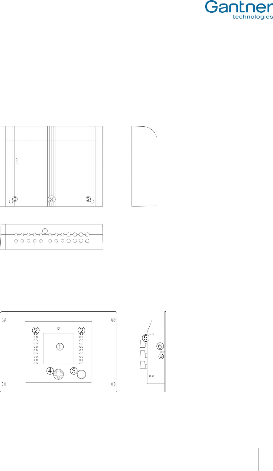
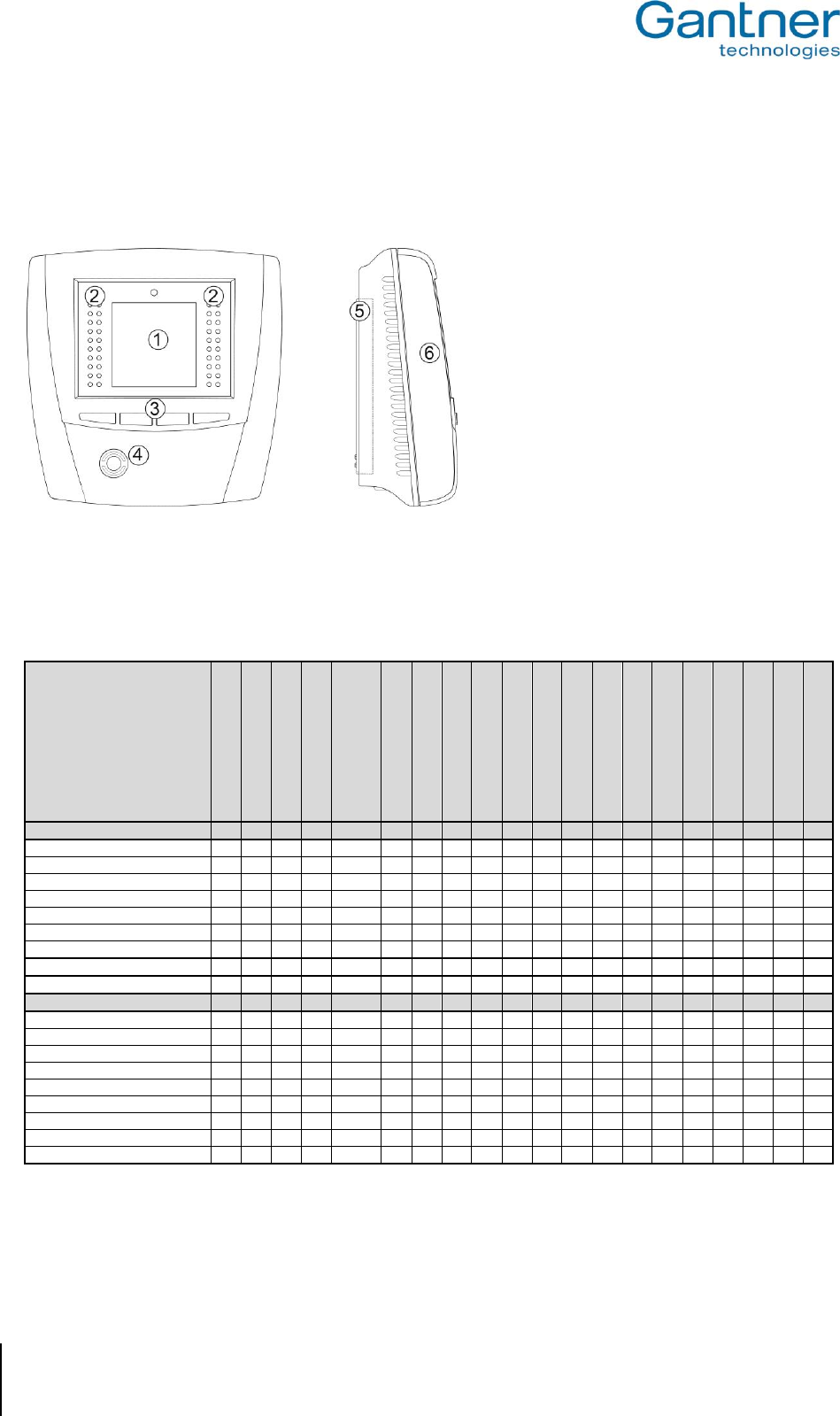
The GAT Access 6100 terminal is used for access control in leisure facilities such as swimming pools, spas and
gyms. It can be installed at turnstiles or gates, which control the entry or exit to certain areas. The access terminal
checks the authorisation of visitors and allows entry through an access point such as a turnstile or gate.
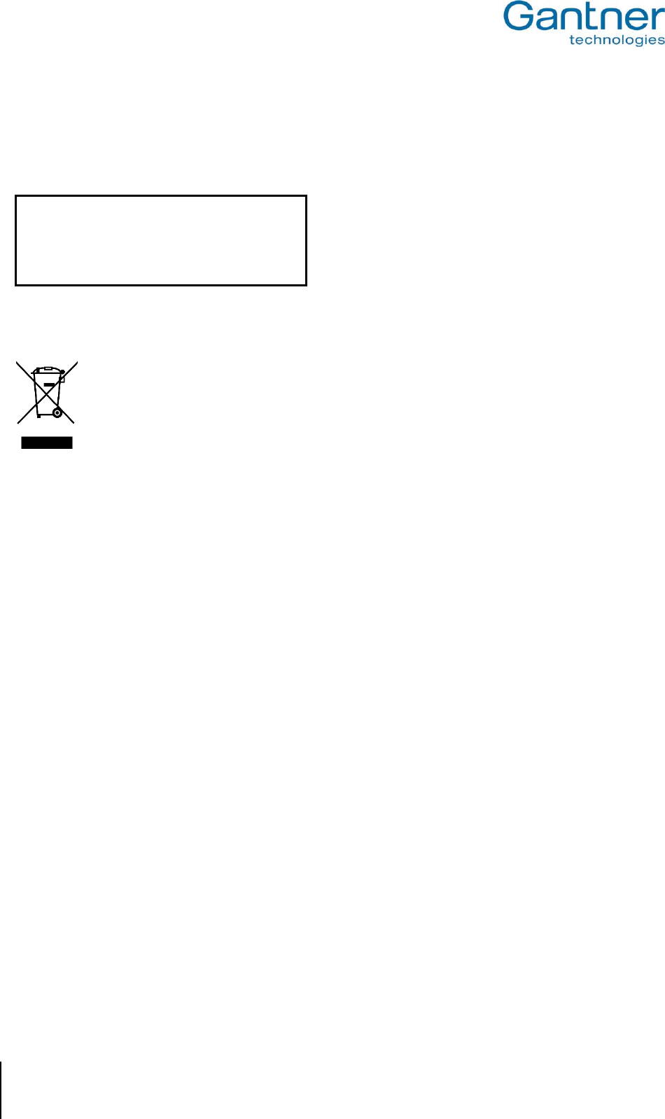
The terminal is designed to be wall-mounted or integrated with a turnstile (using the GAT Holder system). It has a
graphical LC-display, 4 function keys for configuration or user input on the front side, an LED bar with
red/green/yellow lights for status indication and a blue/red/green LED on the RFID scan field.
1 ... Four-segment LED display
2 ... Monochrome display (LCD)
3 ... Function keys
4 ... Illuminated, round scan field
5 ... Device back part
6 ... Device upper part
Figure 1.1 - GAT Access 6100
The GAT Access 6100 F BIO is similar to the GAT Access 6100 F and is equipped with a fingerprint reader for
additional verification of the guest’s identity. If the visitor is authorised to enter the facility AND the fingerprint read
by the terminal’s fingerprint sensor is the same as the fingerprint stored on the user’s data carrier, access is
granted.
1 ... Four-segment LED display
2 ... Monochrome display (LCD)
3 ... Function keys
4 ... Illuminated, round scan field
5 ... Device back part
6 ... Device upper part
7 ... Fingerprint reader GAT FR 055
8 ... Fingerprint sensor of GAT FR 055
9 ... Weather protection cover (optional)
Figure 1.2 - GAT Access 6100 F BIO
GAT Access 6100, GAT Access 6100 F BIO, GAT Access 6100 F Enrollment Station, GAT TimeAxx 6150
General
www.gantner.com
HB_GAT-ACCESS6100--EN_12
9
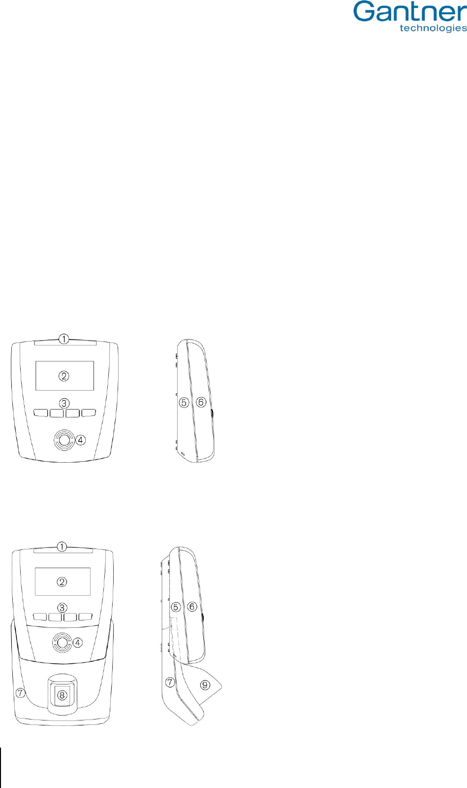
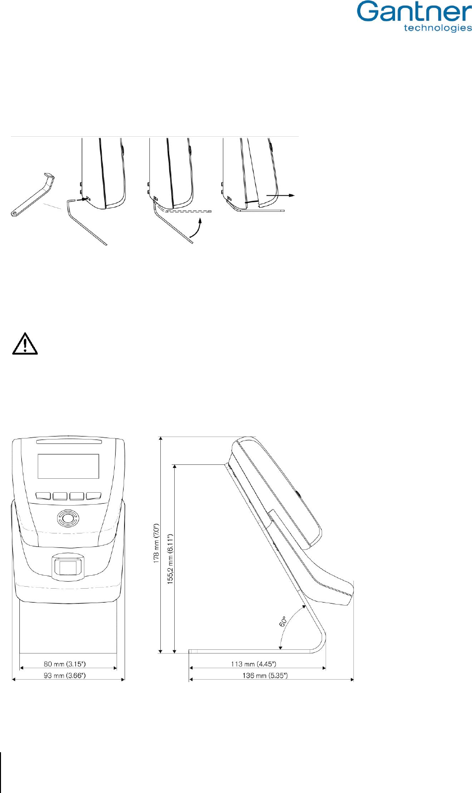
The GAT Access 6100 F Enrollment Station is located at a central location such as the reception desk of a leisure
facility. When visitors first register at the facility the device is used to scan the visitor’s fingerprint(s) and to transmit
the fingerprint data directly onto the visitor’s personal data carrier. The fingerprint data is only ever stored on the
visitor’s data carrier and never in the terminal or any other location in the facility.
1 ... Four-segment LED display
2 ... Monochrome display (LCD)
3 ... Function keys
4 ... Illuminated, round scan field
5 ... Device back part
6 ... Device upper part
7 ... Fingerprint reader
8 ... Fingerprint sensor
9 ... Stand
Figure 1.3 - GAT Access 6100 F Enrollment Station
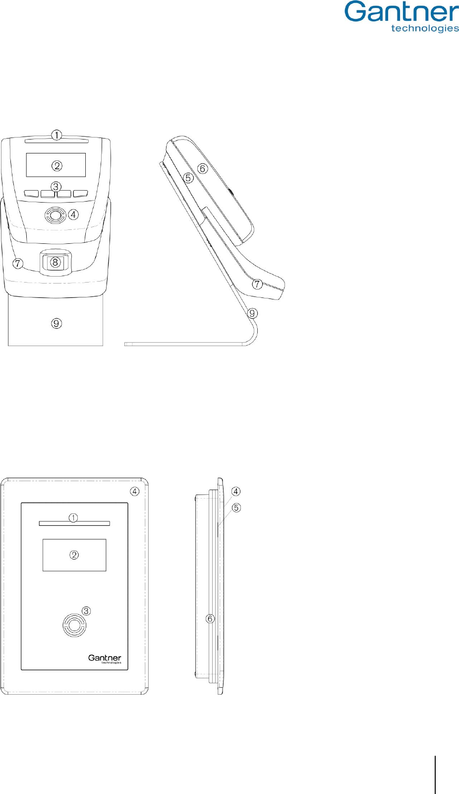
The GAT TimeAxx 6150 is an elegant terminal for public baths, fitness studios and other leisure facilities where the
duration of use of services must be regulated. When used as a shower terminal, the terminal is installed directly in
the shower cubicle (see mounting instructions) and, via a digital output, controls an electrovalve that activates or
deactivates the shower. The remaining time is continuously shown to the user on a large graphical display, which
helps to reduce overall water consumption.
This device has the same electrical hardware as the other GAT Access 6100 terminals but uses a waterproof
housing for flush or surface mounting in shower areas. The terminal also has a display and LED signals, but no
mechanical buttons for user input.
1 ... Four-segment LED display
2 ... Monochrome display (LCD)
3 ... Illuminated, round scan field
4 ... Front frame
5 ... Device upper part (below
the front frame)
6 ... Device back part
Figure 1.4 - GAT TimeAxx 6150

GAT Access 6100, GAT Access 6100 F BIO, GAT Access 6100 F Enrollment Station, GAT TimeAxx 6150
General
10
HB_GAT-ACCESS6100--EN_12
www.gantner.com
1.3 Standard Operation
When a visitor of the leisure facility holds their data carrier next to the illuminated round RFID scan field, the GAT
Access 6100 reads the information on the data carrier and sends the data over the network (Ethernet) to a server
for evaluation. The visitor’s authorisation is checked and a response returned to the GAT Access 6100. When access is
granted, the GAT Access 6100 activates a corresponding relay output that opens the connected turnstile or gate for a
certain time period.
Visitors using the GAT Access 6100 F BIO must also scan their fingerprints (if this is activated) for additional
verification. The terminal compares the scanned fingerprint of a visitor with the data stored on the visitor’s data
carrier and grants access only when the visitor is authorised and the fingerprint data matches.
Different settings for the GAT Access 6xxx, e.g., the access time of a turnstile/gate or the text displayed on the
terminal, can be defined via the configuration settings in GAT Config Manager. See "4.3. Configuration Settings" for
more information on configuring the terminals.
Note: The GAT TimeAxx 6150 operates differently to the description above. After user identification the terminal
activates the external application (e.g., opens the shower valve) and starts a countdown timer. The user can
pause the countdown and restart as required. After a configurable time the terminal deactivates the
application.
1.4 Operating Modes
The GAT Access 6100 access terminals operate in online mode. They must always be connected to a server/host
computer. In Online mode the GAT Access 6100 automatically sends the information of a data carrier over the
interface to the host computer and waits for an appropriate reaction from the host. An exception is the GAT Access
6100 F Enrollment Station, which usually operates in Offline Mode.
For instances where an error occurs or the communication is interrupted, the GAT Access 6100 can switch into
Emergency mode or Out of Order mode (depending on the configuration). For more information about the operating
modes see chapter "6. Communication".
GAT Access 6100, GAT Access 6100 F BIO, GAT Access 6100 F Enrollment Station, GAT TimeAxx 6150
General
www.gantner.com
HB_GAT-ACCESS6100--EN_12
11
1.5 Other Devices in the GAT Access 6xxx Series
In addition to the previously mentioned access devices in the GAT Access 6100 family, GANTNER Electronic
GmbH also offers the following access terminals in the 6xxx series.
GAT Access 6200
This is an access terminal for hidden installation and with a connected external antenna for reading the data carriers
of the visitors. The terminal itself has no display or keys for operation. More information on the GAT Access 6200 is
available in a separate manual.
1 ... Cable inlet
2 ... Screws for locking the housing
3 ... Mechanical lock
Figure 1.5 - GAT Access 6200
GAT Access 6350
This access terminal has a monochrome display, signal lights and an internal reader to read the visitor’s data
carriers. The terminal is designed to integrate with access hardware such as turnstiles. More information on the
GAT Access 6350 is available in a separate manual.
1 ... Monochrome display (LCD)
2 ... Traffic light display (red/green)
3 ... Acknowledge key
4 ... Illuminated, round scan field
5 ... Screw terminals for cable connection
6 ... Housing
Figure 1.6 - GAT Access 6350
GAT Access 6100, GAT Access 6100 F BIO, GAT Access 6100 F Enrollment Station, GAT TimeAxx 6150
General
12
HB_GAT-ACCESS6100--EN_12
www.gantner.com
GAT Access 6500
This access terminal has a monochrome display, traffic light status display and internal reader, just like the GAT
Access 6350. The difference to the GAT Access 6350 is that the housing of the GAT Access 6500 is designed for
installation onto a wall or holder. The description of the GAT Access 6500 is available in a separate manual.
1 ... Monochrome display (LCD)
2 ... Traffic light display (red/green)
3 ... Function keys
4 ... Illuminated, round scan field
5 ... Mounting frame
6 ... Display unit
Figure 1.7 - GAT Access 6500
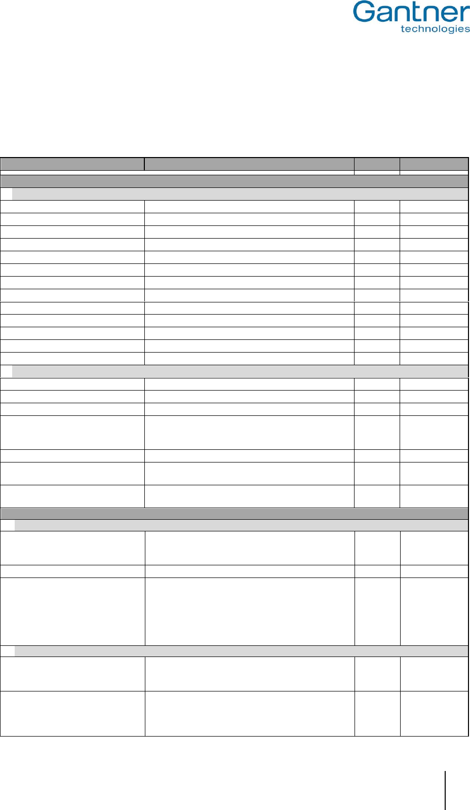
1.6 Function Matrix for the GAT Access Devices
Table 1.1 gives an overview of the functionalities of the different GAT Access devices and the connectible hardware.
GAT Access 6100 B
GAT Access 6100 F
GAT Access 6100 ISO
GAT Access 6100 F BIO
GAT Access 6100 F
Enrollment Station
GAT TimeAxx 6150 B
GAT TimeAxx 6150 F
GAT TimeAxx 6150 ISO
GAT Access 6200 B
GAT Access 6200 F
GAT Access 6200 ISO
GAT Access 6350 B
GAT Access 6350 F
GAT Access 6350 ISO
GAT Access 6500 B
GAT Access 6500 F
GAT Access 6500 ISO
GAT Access 6600 B
GAT Access 6600 F
GAT Access 6600 ISO
Online Functions
UID (card number)
X
X
X
X
X
X
X
X
X
X
X
X
X
X
X
X
X
X
X
X
Read locker data
X
X
X
X
X
X
X
X
X
X
X
X
X
X
X
X
X
X
X
X
Read cash 1 data
X
-
-
-
-
X
-
-
X
-
-
X
-
-
X
-
-
X
-
-
Read cash 2 data
X
-
-
-
-
X
-
-
X
-
-
X
-
-
X
-
-
X
-
-
Write locker check-in
X
X
X
X
X
X
X
X
X
X
X
X
X
X
X
X
X
X
X
X
Emergency operation
X
X
X
X
X
X
X
X
X
X
X
X
X
X
X
X
X
X
X
X
Offline Emergency mode2)
-
X
-
-
-
-
X
-
-
-
-
-
-
-
-
-
-
-
-
-
Bookings
X
X
X
X
X
X
X
X
X
X
X
X
X
X
X
X
X
X
X
X
Check FID and Sub-FID 1)
X
X
X
X
X
X
X
X
X
X
X
X
X
X
X
X
X
X
X
X
Device parts
Display
X
X
X
X
X
X
X
X
-
-
-
X
X
X
X
X
X
X
X
X
Number of function keys
4
4
4
4
4
0
0
0
4*
4*
4*
4*
4*
4*
4
4
4
4*
4*
4*
Internal antenna
X
X
X
X
X
X
X
X
-
-
-
X
X
X
X
X
X
X
X
X
External antenna
-
-
-
-
-
-
-
-
X
X
X
X
X
X
X
X
X
X
X
X
Serial Interface RS 485
-
-
-
-
-
-
-
-
X
X
X
X
X
X
X
X
X
X
X
X
Ethernet TCP/IP
X
X
X
X
X
X
X
X
X
X
X
X
X
X
X
X
X
X
X
X
Relay outputs
1
1
1
1
1
1
1
1
4
4
4
4
4
4
4
4
4
4
4
4
Optocoupler inputs
1
1
1
1
1
1
1
1
4
4
4
4
4
4
3
3
3
4
4
4
Barcode
-
-
-
-
-
-
-
-
X
X
X
X
X
X
X
X
X
X
X
X
X ... Available * .... On the rear/inside of device
- .... Not available 1) … The FID and Sub-FID check depends on the configuration
2) … Requires "GAT Access 6100 F Upgrade” licence, see "4.4. Configuration of Offline
Emergency Mode for a GAT Access 6100 "
Table 1.1 - Function matrix of the GAT Access 6xxx devices
GAT Access 6100, GAT Access 6100 F BIO, GAT Access 6100 F Enrollment Station, GAT TimeAxx 6150
General
www.gantner.com
HB_GAT-ACCESS6100--EN_12
13
1.7 Special Functions and Options
1.7.1 GAT Device Finder Support
The GAT Access 6100 terminals implement the Device Finding technology from GANTNER Electronic GmbH,
which allows devices on a TCP/IP network to be found without knowing their exact IP addresses or network name.
The GAT Device Finder software scans a TCP/IP network and lists all found devices.
Figure 1.8 - GAT Device Finder Support
The Device Finding technology uses the UDP protocol and port 8216. All GAT Access 6100 are set to use this port
8216 by default.

GAT Access 6100, GAT Access 6100 F BIO, GAT Access 6100 F Enrollment Station, GAT TimeAxx 6150
General
14
HB_GAT-ACCESS6100--EN_12
www.gantner.com
GAT Access 6100, GAT Access 6100 F BIO, GAT Access 6100 F Enrollment Station, GAT TimeAxx 6150
Mounting the GAT Access 6100 Terminals
www.gantner.com
HB_GAT-ACCESS6100--EN_12
15
2. MOUNTING THE GAT ACCESS 6100 TERMINALS
The GAT Access 6100 devices can be mounted directly onto a flat surface such as a wall.
Attention: The GAT Access 6100 must not be mounted directly onto a metallic surface as this can
negatively affect the reading field so that the data carriers may not be read anymore.
In the following sections the mounting of the GAT Access 6100 and GAT Access 6100 F BIO are described. The
GAT Access 6100 F Enrollment Station has a stand and can just be placed, for example, onto a table without
mounting.
For the mounting of the GAT TimeAxx 6150 terminal see "2.4 GAT TimeAxx 6150".
2.1 GAT Access 6100
2.1.1 Wall Mounting
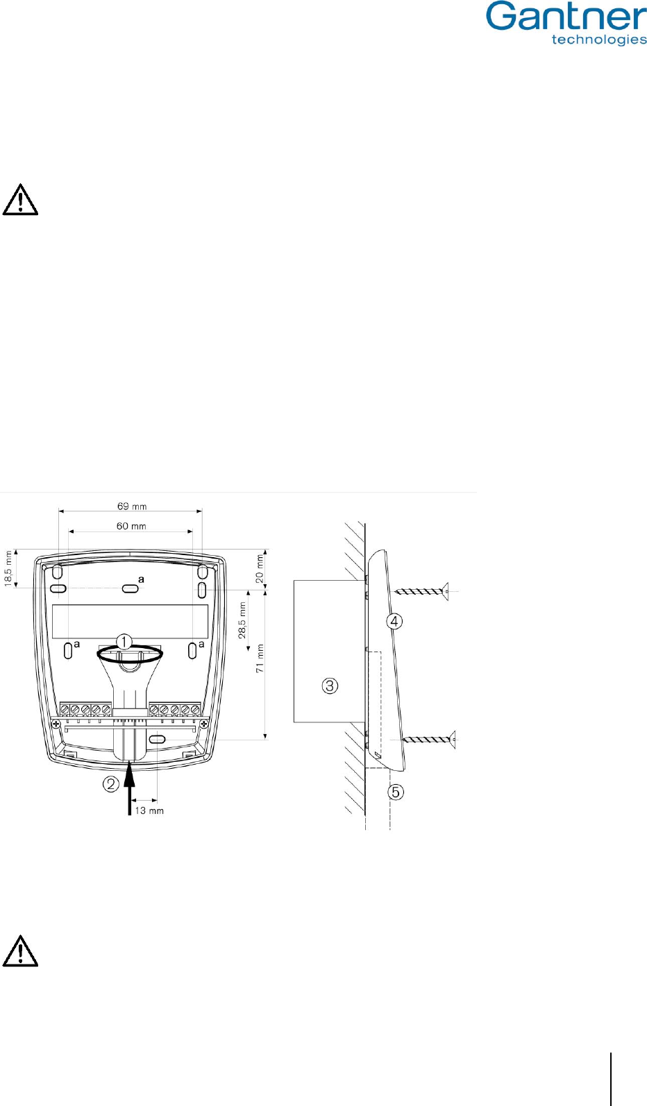
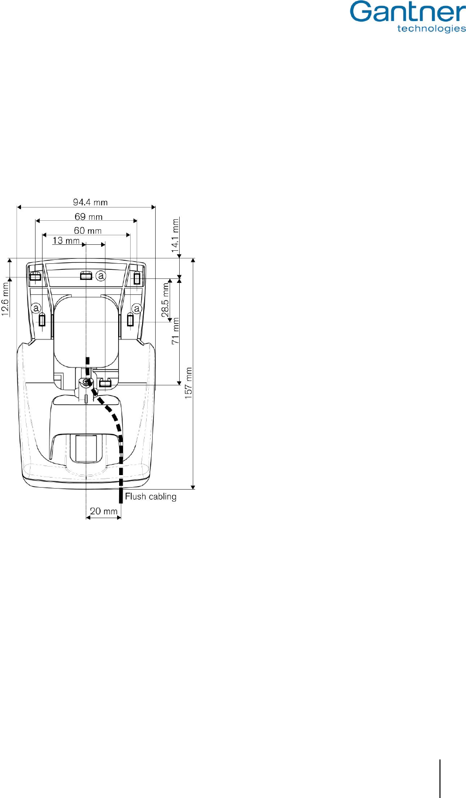
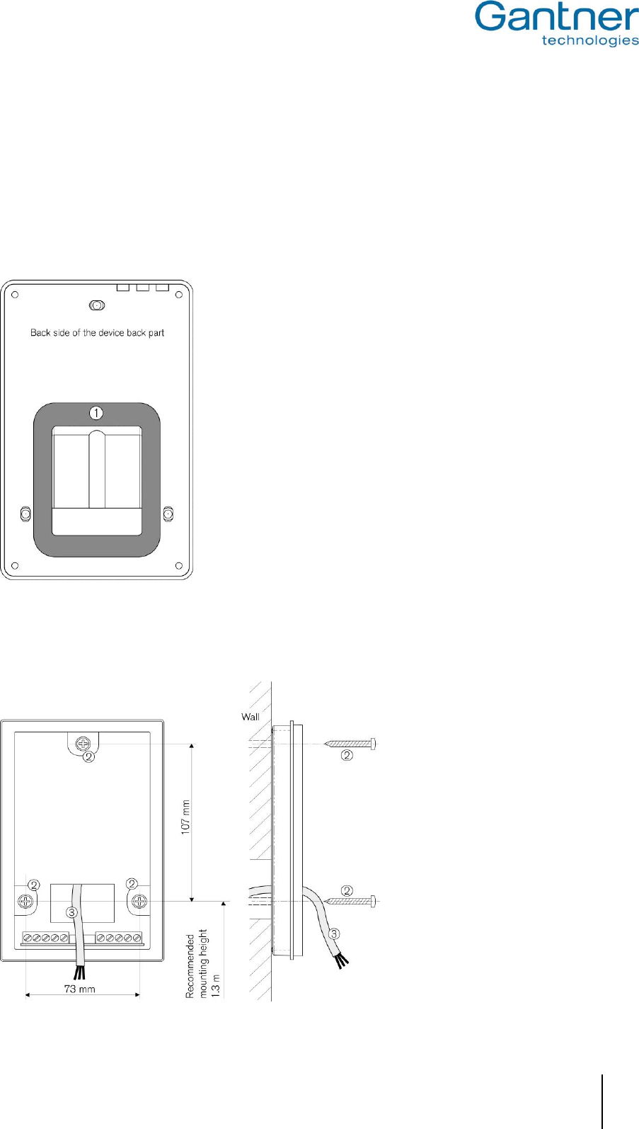
First, the device back part of the GAT Access 6100 is secured by screws to a flat background (e.g. concrete wall).
When fixing to an uneven background the device back part must not be distorted, as this will prevent correct
connection of the upper part. The recommended mounting height from the top edge of the device to the floor is 1.3
meters.
1. Flush-mounted cable
2. Surface-mounted cable
3. Back box
4. Device back part
5. Cable conduit for surface
cable connection
Figure 2.1 - Mounting measures
Cable Inlets
The housing of the GAT Access 6100 has cable inlets both, for flush (1) or surface (2) installed cables.
When the cables are surface mounted please check whether the cables can still be inserted once the device back
part has been mounted, otherwise run the cables through the cable lead-ins prior to securing.
Attention: See chapter "3. Electrical Connections" for information about the electrical connection. The
connection of the cables must always be performed in powerless state!
GAT Access 6100, GAT Access 6100 F BIO, GAT Access 6100 F Enrollment Station, GAT TimeAxx 6150
Mounting the GAT Access 6100 Terminals
16
HB_GAT-ACCESS6100--EN_12
www.gantner.com
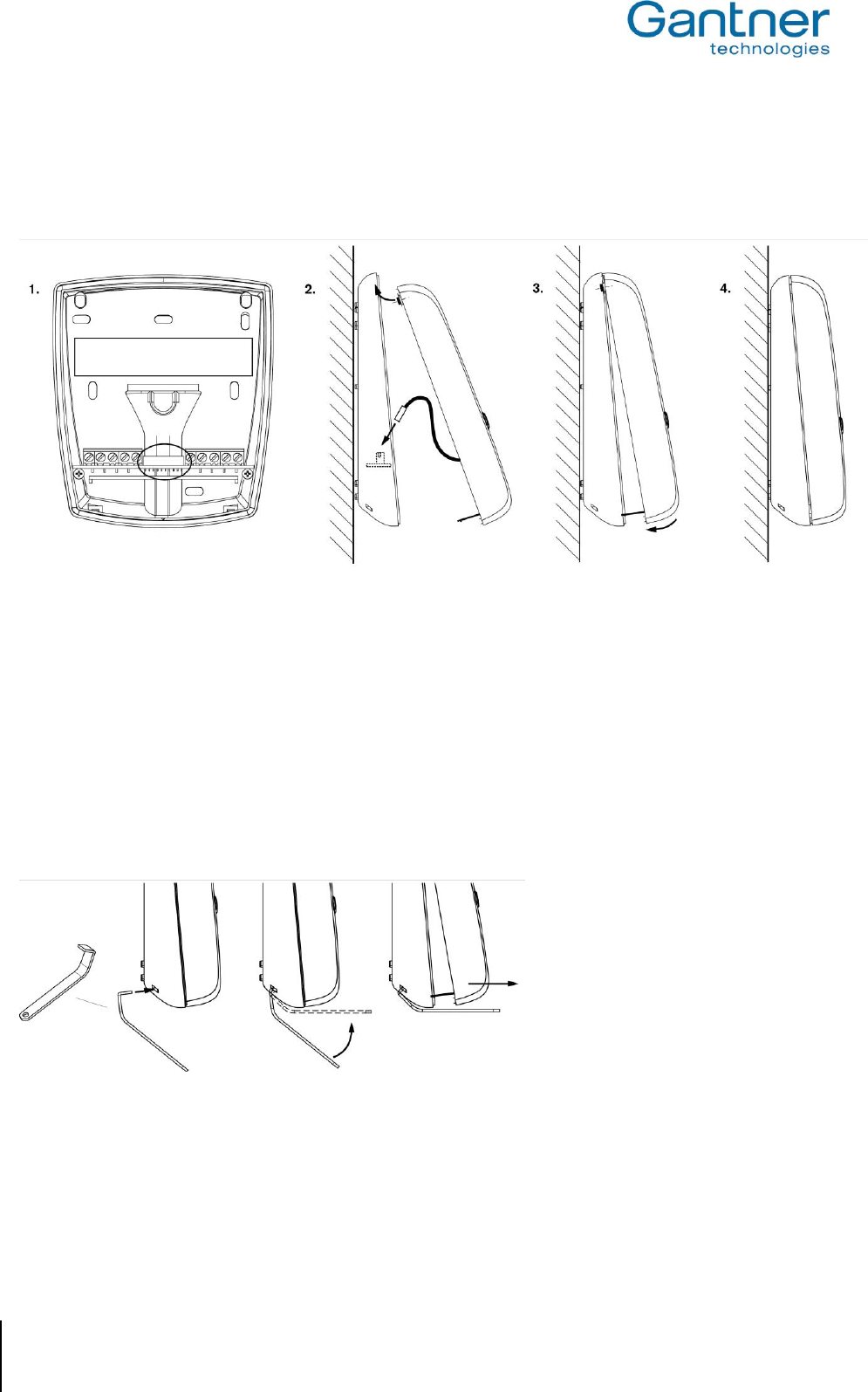
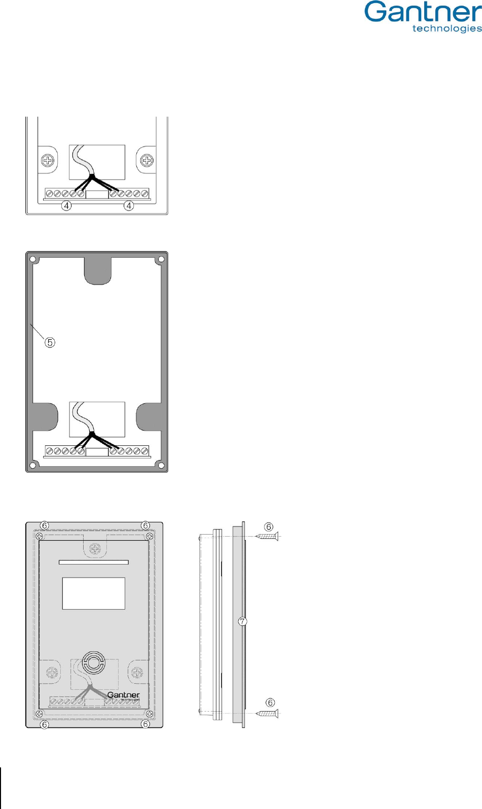
Mounting the Device Upper Part
Once the connection cables are terminated, the device back part and upper part are connected together via a
connection cable (already connected in the upper part) and the two parts are fixed together.
Figure 2.2 - Connection and mounting of the device upper part
Notes:
1. Check the socket in the device back part (circled in figure 1). Dirt, dust and humidity must be removed so that a
good contact of the connection cable is guaranteed. No aggressive detergent may be used. Please do not
damage socket contacts.
Attention: Cleaning only in powerless state.
2. Plug in the connection cable into the socket in the device back part (consider alignment) and clip the top of the
device upper part into the device back part.
3. Swing down the device upper part until it clicks.
4. The device can only be opened with the supplied special tool! With this, the two catches on the bottom of the
device can be unlocked in succession.
Figure 2.3 - Opening the housing
GAT Access 6100, GAT Access 6100 F BIO, GAT Access 6100 F Enrollment Station, GAT TimeAxx 6150
Mounting the GAT Access 6100 Terminals
www.gantner.com
HB_GAT-ACCESS6100--EN_12
17
2.2 GAT Access 6100 F BIO
2.2.1 Wall Mounting
First, the back part of the GAT FR 055 reader is secured by 3 screws (a) to a flat background (e.g. concrete wall)
according to the following dimensional drawing. When fixing to an uneven background the device back part must
not be distorted, as this will prevent correct connection of the upper part. The recommended mounting height from
the top edge of the device to the floor is 1.3 meters.
.
Figure 2.4 - Dimensions of GAT FR 055 back part and mounting holes (a)
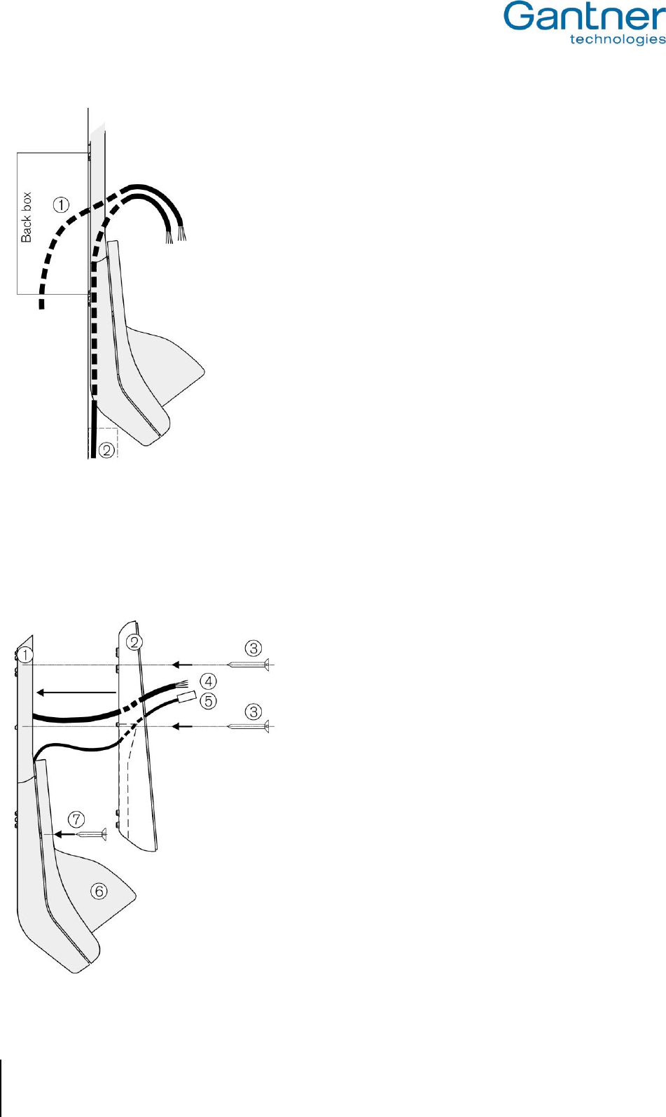
Connection Cables
The connection cables (power supply, network etc.) are run through the cable lead-ins of the GAT FR 055. With
concealed/flush wiring (1) the connection cables are fed from behind via the back box. With surface wiring (2) the
connection cables must lie in the cable duct on the back part of the GAT FR 055.
GAT Access 6100, GAT Access 6100 F BIO, GAT Access 6100 F Enrollment Station, GAT TimeAxx 6150
Mounting the GAT Access 6100 Terminals
18
HB_GAT-ACCESS6100--EN_12
www.gantner.com
Figure 2.5 - Dimensions of GAT FR 055 back part and mounting holes (a)
Mounting the GAT Access 6100 F Back Part
Pay attention when fixing to an uneven background that the GAT FR 055 housing and the device back part of the
GAT Access 6100 F must not be distorted. Recommended mounting height from the top edge of the device to the
floor is 1.3 m.
1. GAT FR 055
2. Device back part of GAT Access 6100 F
3. Fastening screws
4. Connection cable
5. Connection cable GAT FR 055 to GAT Access 6100 F
6. Weather protection cover (optional)
7. Fastening screws for weather protection cover
Figure 2.6 - Mounting the GAT Access 6100 F back part
GAT Access 6100, GAT Access 6100 F BIO, GAT Access 6100 F Enrollment Station, GAT TimeAxx 6150
Mounting the GAT Access 6100 Terminals
www.gantner.com
HB_GAT-ACCESS6100--EN_12
19
Electrical Connection
The connection cables (see (4) in Figure 2.6) are connected at the device back part of the GAT Access 6100 F.
Attention: See chapter "3. Electrical Connections" for information about the electrical connection. The
connection of the cables must always be performed in powerless state!
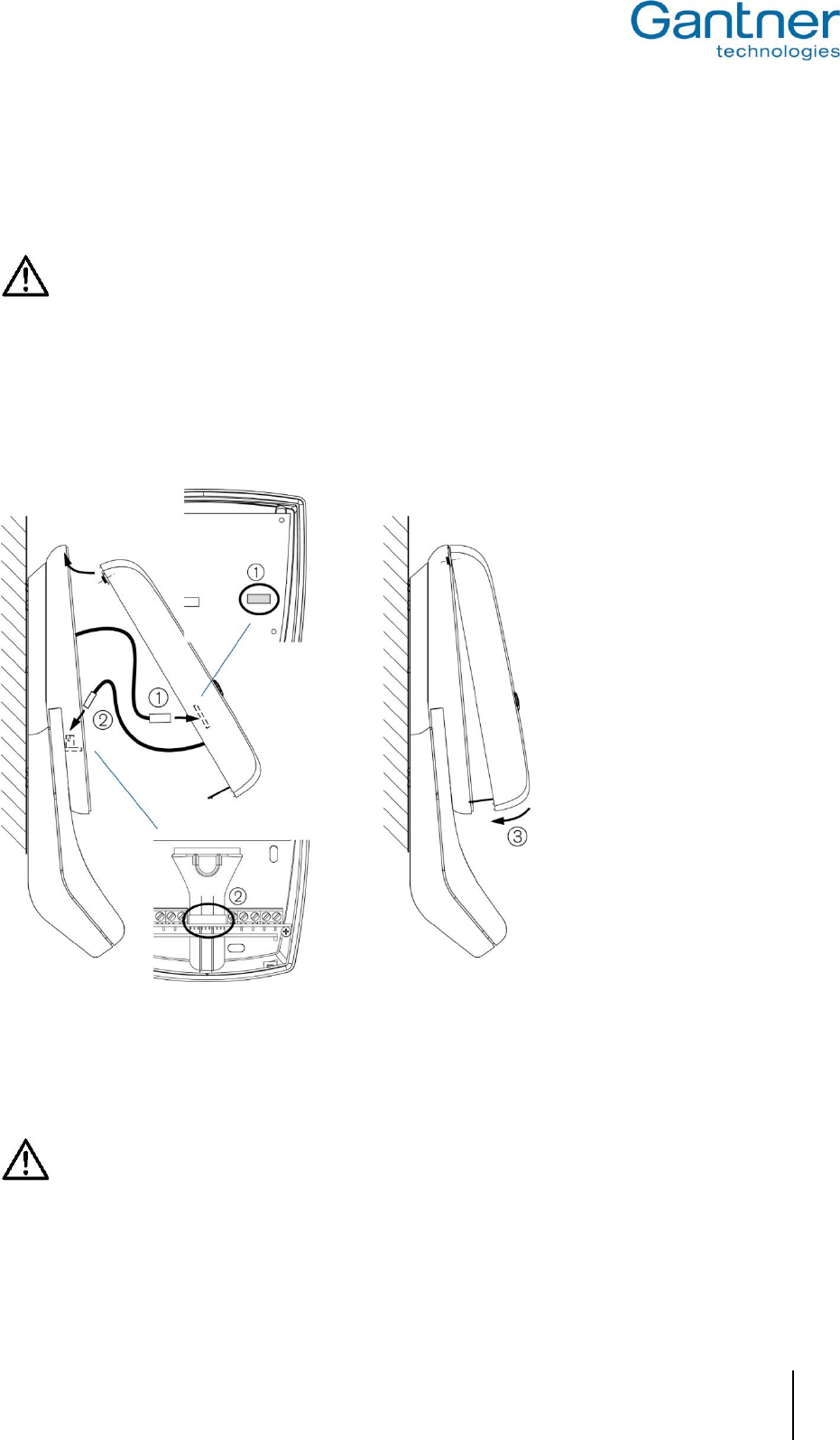
Mounting of the GAT Access 6100 F Upper Part
The connection cable of the GAT FR 055 (1) is plugged into the housing upper part of the GAT Access 6100 F and
the connection cable of the upper part (2) is plugged into the back part of the GAT Access 6100 F. Next, the device
upper part can be swung down into the back part (3).
Figure 2.7 - Mounting the GAT Access 6100 F back part
Check the sockets (1) and (2)! Dirt, dust and humidity must be removed so that a good contact of the connection
cable is guaranteed. No aggressive detergent may be used. Please do not damage socket contacts.
Attention: Cleaning must always be performed in powerless state!
GAT Access 6100, GAT Access 6100 F BIO, GAT Access 6100 F Enrollment Station, GAT TimeAxx 6150
Mounting the GAT Access 6100 Terminals
20
HB_GAT-ACCESS6100--EN_12
www.gantner.com
Opening the GAT Access 6100 F Upper Part
The device can only be opened with the supplied special tool! With this, the two catches on the bottom of the device
can be unlocked in succession.
Figure 2.8 - Opening the housing
Maintenance
The sensor field of the GAT FR 055 should be cleaned from time to time so that fingerprints can be clearly scanned.
Attention: To clean the sensor field always use a damp (not wet!), smooth cloth. Acrid detergents and no
sharp materials must not be used.
2.3 GAT Access 6100 F Enrollment Station
The GAT Access 6100 F Enrollment Station is mounted onto a stainless-steel stand and placed directly on a table
or similar.
Figure 2.9 - Dimensions of the GAT Access 6100 F Enrollment Station
GAT Access 6100, GAT Access 6100 F BIO, GAT Access 6100 F Enrollment Station, GAT TimeAxx 6150
Mounting the GAT Access 6100 Terminals
www.gantner.com
HB_GAT-ACCESS6100--EN_12
21
2.4 GAT TimeAxx 6150
Though the GAT TimeAxx 6150 housing is specially designed for flush mounting that only the front is visible, it can
also be mounted onto a surface such as a wall without any back box.
2.4.1 Surface Mounting
1. Apply silicone around the cable entrance on the device back part. This is necessary to seal the housing after it is
mounted on the wall.
Apply the silicone on the slightly recessed area (1) around the cable entrance. The amount of silicone must be
dosed so that after pressing the device to the wall the cable entrance is completely sealed.
2. Mount the device back part to the wall by using the three screws (2). Recommended mounting height is 1.3 m.
GAT Access 6100, GAT Access 6100 F BIO, GAT Access 6100 F Enrollment Station, GAT TimeAxx 6150
Mounting the GAT Access 6100 Terminals
22
HB_GAT-ACCESS6100--EN_12
www.gantner.com
3. Connect the connection cables at the screw terminal strips (4) in the device back part. For a description of the
pin assignment and electrical specifications see "3. Electrical Connections".
4. Insert the rubber seal (5) in the device back part.
5. Attach the device upper part with the front print (7) by using the four screws included in the package of the GAT
TimeAxx 6150 (6). Pay attention that the rubber seal is total closed around the housing.
GAT Access 6100, GAT Access 6100 F BIO, GAT Access 6100 F Enrollment Station, GAT TimeAxx 6150
Mounting the GAT Access 6100 Terminals
www.gantner.com
HB_GAT-ACCESS6100--EN_12
23
6. Push on the front frame (8). It holds in place with latches, without the need for screws.
2.4.2 Flush Mounting
For flush mounting of the GAT TimeAxx 6150 a back box is shipped together with the terminal. This back box can
also be ordered as a separate article (GAT TimeAxx 6150 UP, Part No: 532325).
Using the back box the GAT TimeAxx 6150 can be installed in brickwork, concrete and cavity walls.
a) Installation in Brickwork Walls
GAT Access 6100, GAT Access 6100 F BIO, GAT Access 6100 F Enrollment Station, GAT TimeAxx 6150
Mounting the GAT Access 6100 Terminals
24
HB_GAT-ACCESS6100--EN_12
www.gantner.com
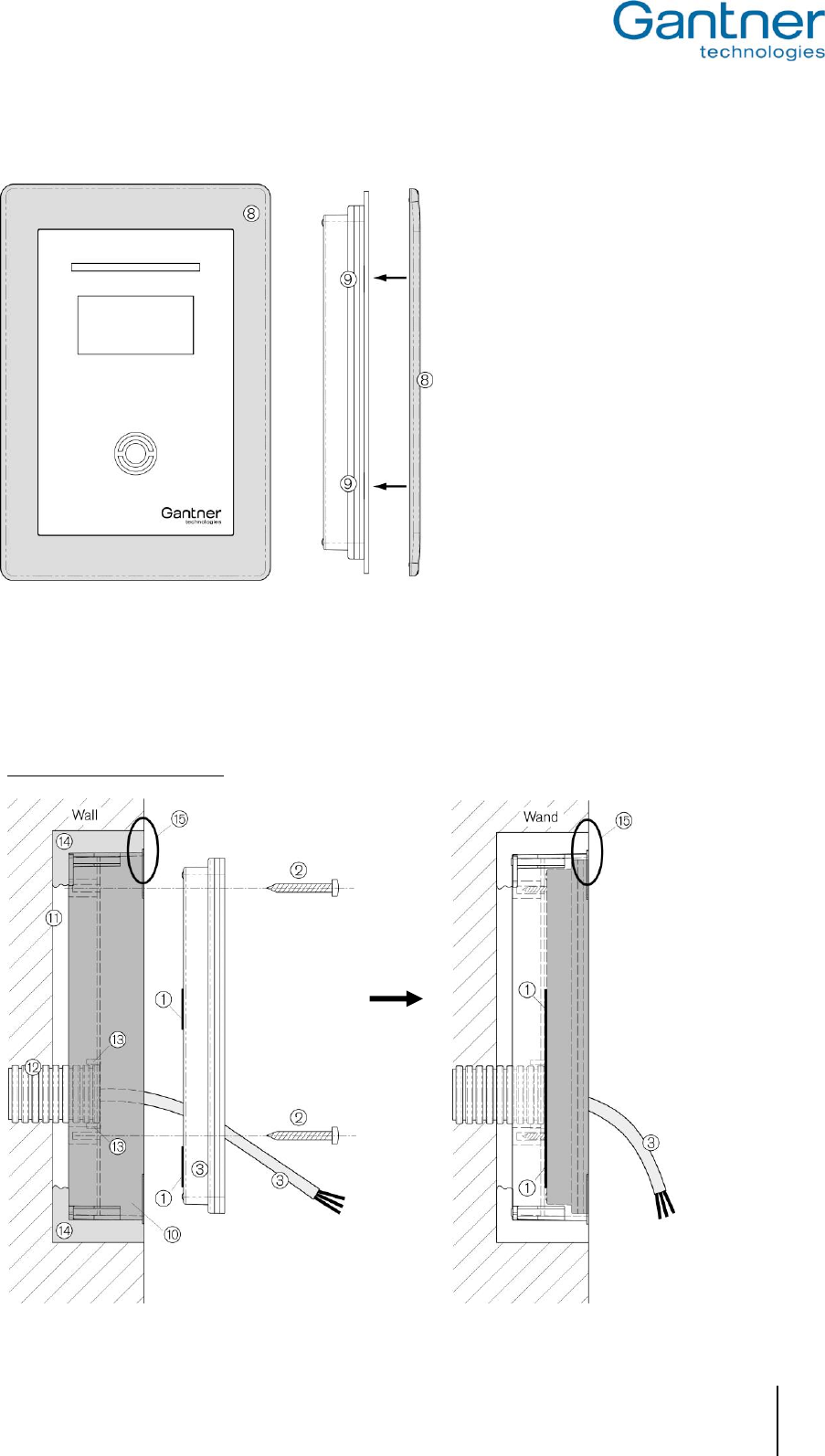
1. Insert the FX tube (12) with the connection cable (3) into the opening of the back box. The opening is designed
for an FX tube with 25 mm outer diameter. In this case, the lugs (13) at the opening are holding the FX tube in
place.
2. Insert the back box (10) into the wall recess (11) and make sure, that it is flush with the wall surface (see 15).
Fix the back box e.g. with plaster or PU foam (14).
3. Feed the connection cable (3) through the opening of the GAT TimeAxx 6150 back part.
4. Caulk the edge of the cable opening in the GAT TimeAxx 6150 back part with silicone (1) -> see also step 1 at
the description of the surface mounting.
5. Mount the GAT TimeAxx 6150 into the back box by using three screws (2). This is done the same way as
described in Step 2 of the surface mounting. Pay attention, that the cable opening is completely sealed with the
previously applied silicone.
6. The remaining mounting procedure is the same as described at the surface mounting, beginning with step 3
onward.
Attention: To finish the installation the GAT TimeAxx 6150 must be hermetically sealed. Humidity/water
must never be able to penetrate into the housing. Pay special attention that the silicone
applied in step 4 seals the housing completely and that the rubber seal (see step 4 of surface
mounting) is inserted correctly and seals the housing in its entire length.
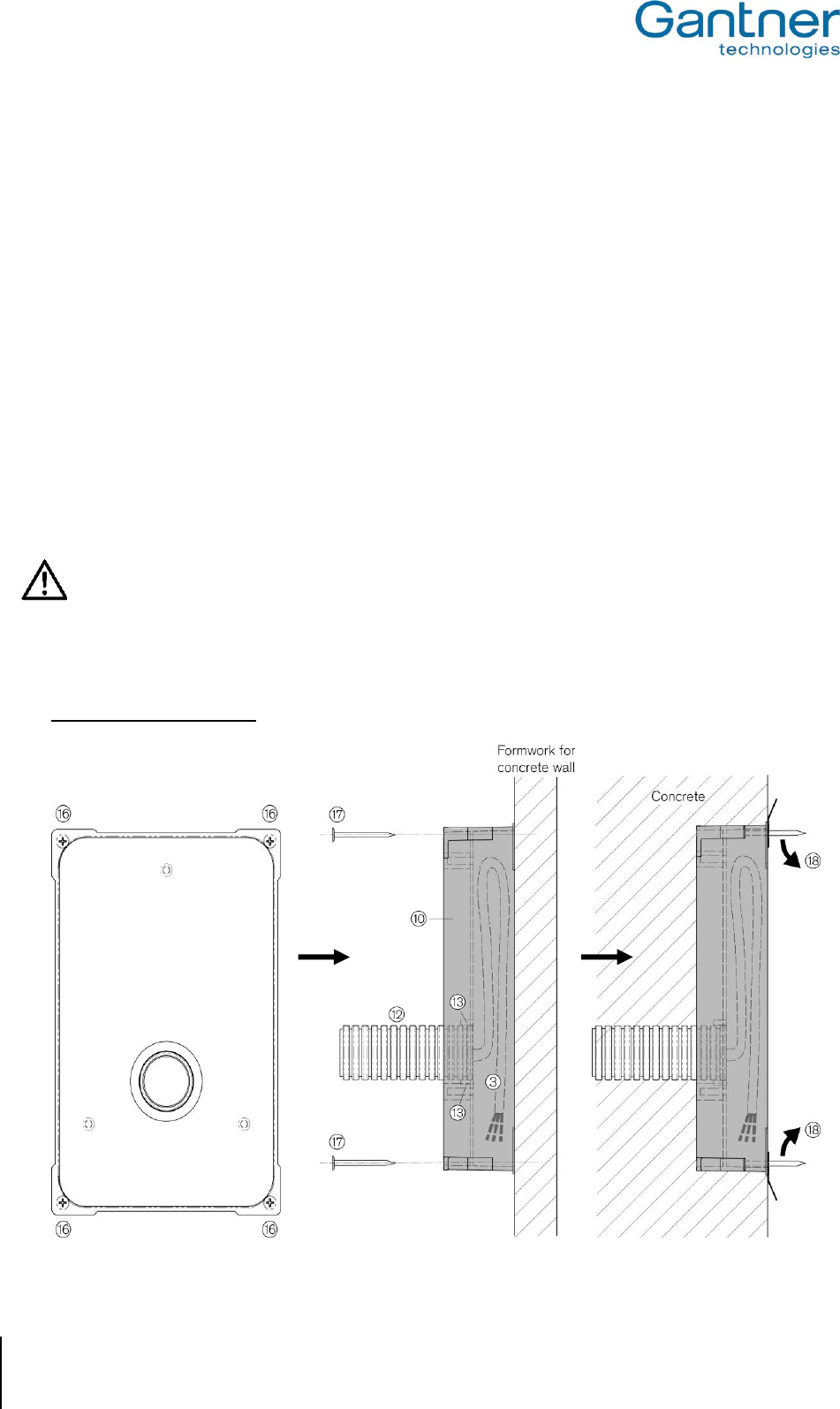
b) Installation in Concrete Walls
1. Unscrew the four screws of the back box (16) and remove them, together with the metal lugs.
GAT Access 6100, GAT Access 6100 F BIO, GAT Access 6100 F Enrollment Station, GAT TimeAxx 6150
Mounting the GAT Access 6100 Terminals
www.gantner.com
HB_GAT-ACCESS6100--EN_12
25
2. Insert the FX tube (12) with the connection cable (3) into the opening of the back box. The opening is
designed for an FX tube with 25 mm outer diameter. In this case, the lugs (13) at the opening are holding
the FX tube in place.
3. Place the back box (10) inside first onto the concrete formwork and nail it onto the formwork by using four
nails (17) at the holes where the screws (16) had been removed in step 1. Pay attention that the back box
lies flat, without any gap, on the formwork.
If the connection cable (3) is already drawn-in, the cable must be placed inside the back box.
4. After the wall is concreted and hardened and the formwork is removed, cut the nails on the front side (18).
5. The remaining mounting procedure is the same as described for installation in masonry walls (see previous
section a) ).
Attention: To finish the installation the GAT TimeAxx 6150 must be hermetically sealed. Humidity/water
must never be able to penetrate into the housing. Pay special attention that the silicone
applied in step 4 seals the housing completely and that the rubber seal (see step 4 of surface
mounting) is inserted correctly and seals the housing in its entire length.
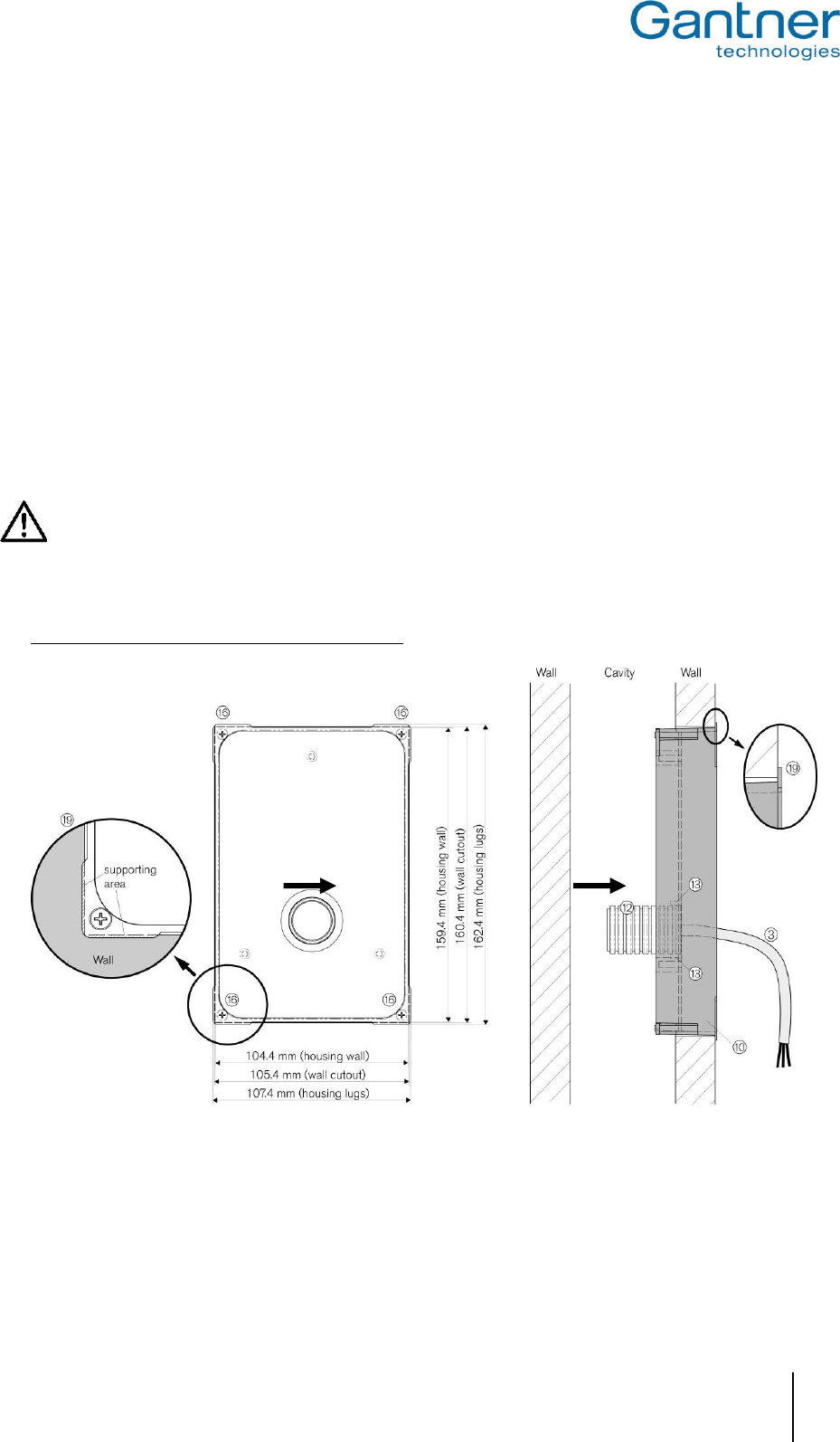
c) Installation in Cavity Walls (e.g. Plasterboard Walls)
1. Cut-out a rectangle hole of 105.4 x 160.4 mm in the wall. The cut-out must not be larger than 107 x 162 mm,
because the lugs of the back box must lie on the wall (see 19).
2. Insert the FX tube (12) with the connection cable (3) into the opening of the back box. The opening is designed
for an FX tube with 25 mm outer diameter. In this case, the lugs (13) at the opening are holding the FX tube in
place.
GAT Access 6100, GAT Access 6100 F BIO, GAT Access 6100 F Enrollment Station, GAT TimeAxx 6150
Mounting the GAT Access 6100 Terminals
26
HB_GAT-ACCESS6100--EN_12
www.gantner.com
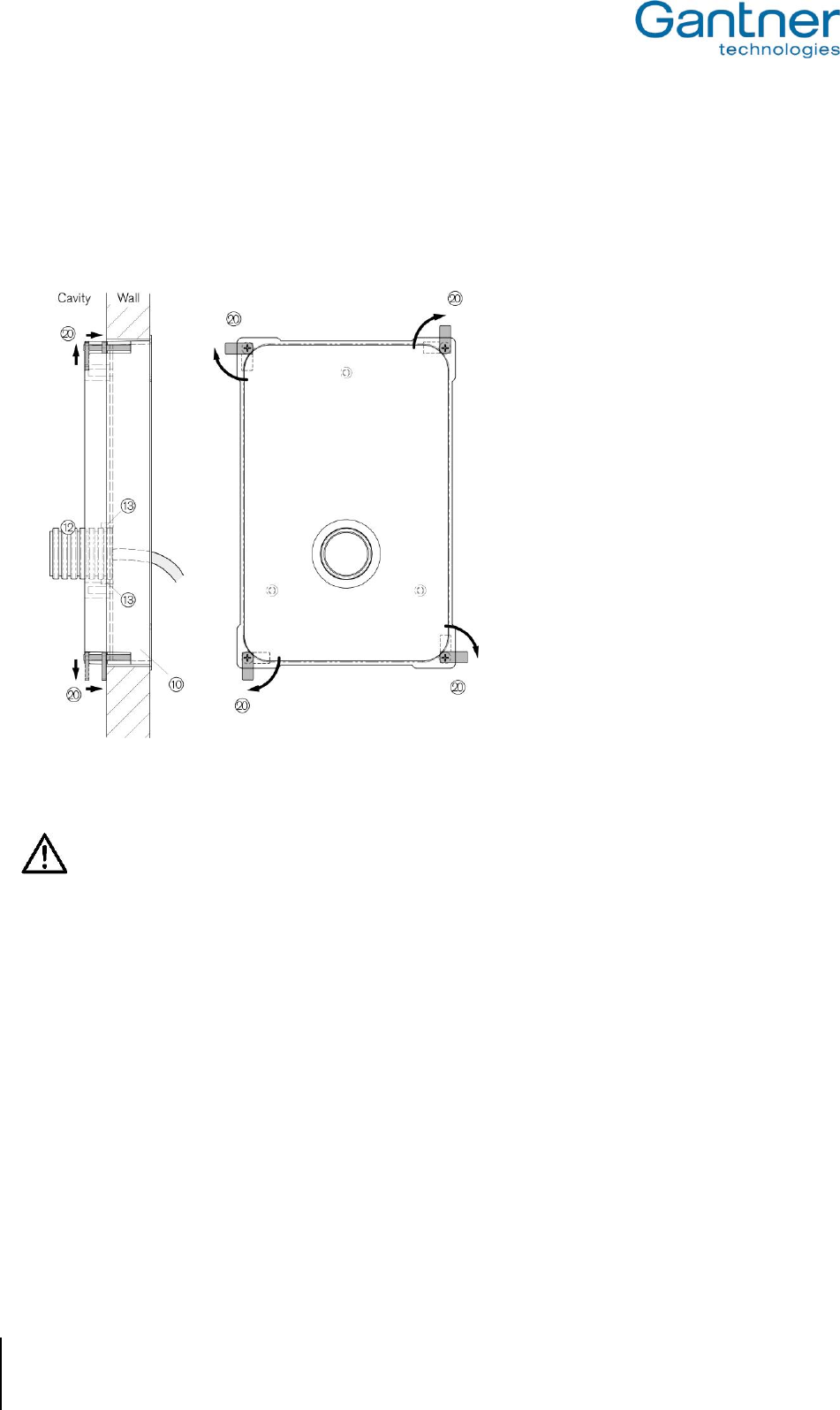
3. Insert the back box (10) into the cut-out in the wall. The four corner lugs of the back box must lie on the wall
(19).
4. Turn the four mounting screws (16) to the right. This will first also turn the lugs at the screws (20) by 90° to the
right and then pull them forward. Turn the screws until the lugs hit the inside of the wall, which will fix the back
box in place.
5. The remaining mounting procedure is the same as described at the installation in brickwork walls (see page 4).
Attention: To finish the installation the GAT TimeAxx 6150 must be hermetically sealed. Humidity/water
must never be able to penetrate into the housing. Pay special attention that the silicone
applied in step 4 seals the housing completely and that the rubber seal (see step 4 of surface
mounting) is inserted correctly and seals the housing in its entire length.
GAT Access 6100, GAT Access 6100 F BIO, GAT Access 6100 F Enrollment Station, GAT TimeAxx 6150
Electrical Connections
www.gantner.com
HB_GAT-ACCESS6100--EN_12
27
3. ELECTRICAL CONNECTIONS
The connection cables for power supply, data signals and peripheral devices are connected at the screw terminals
on the housing upper part.
Attention: Always disconnect or switch-off power supply before connecting or disconnecting cables at the
GAT Access 6100 in order to avoid injuries for persons and damage to the access terminal!
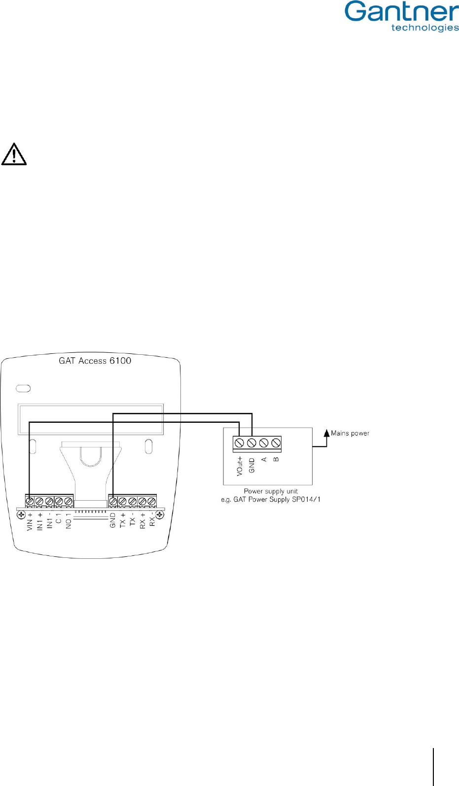
3.1 Power Supply
The GAT Access 6100 terminals need a power supply between 12 and 24 VDC (see technical data). The power can
be supplied for example by the GAT Power Supply SP014/1 or by the GAT Power Supply SP 031/1 from GANTNER
Electronic GmbH. The power input is protected against reverse-polarity.
Note: If several GAT Access 6100 devices or other devices shall use a single power source, please check the max.
power output of the supply unit. For example, one GAT Power Supply SP014/1 can supply two GAT Access
6100.
Note: The GAT Access 6100 F Enrollment Station is equipped with an already connected power supply unit, which
can be plugged into mains power UAC 230 V.
Figure 3.1 - Power supply of a GAT Access 6100 with a GAT Power Supply SP014/1
GAT Access 6100, GAT Access 6100 F BIO, GAT Access 6100 F Enrollment Station, GAT TimeAxx 6150
Electrical Connections
28
HB_GAT-ACCESS6100--EN_12
www.gantner.com
3.2 Network
The GAT Access 6100 terminals are equipped with an Ethernet interface for communication via a LAN network.
3.2.1 Ethernet Network
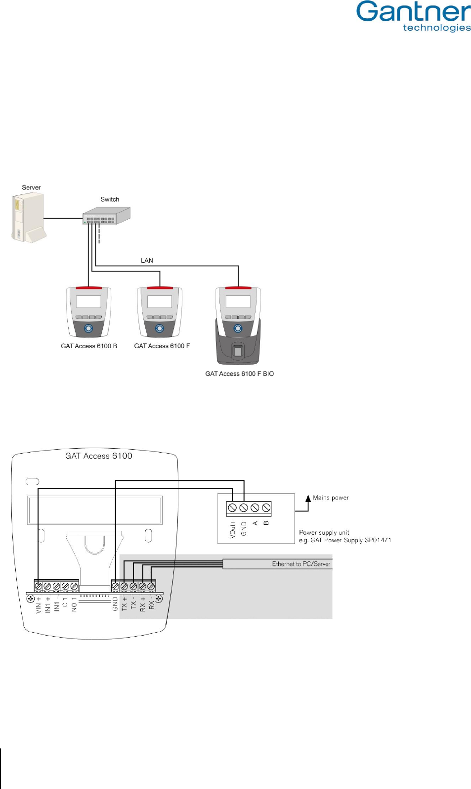
The GAT Access 6100 support 10 and 100 Mbit/s communication. It is recommended to connect each GAT Access
6100 directly to a switch or patch panel socket.
Figure 3.2 - Ethernet network example
The Ethernet network cable is connected to the GAT Access 6100 via the TX+, TX-, RX+, RX- screw terminals. No
RJ 45 plug is used. The wires of the Ethernet cable are directly connected to the screw terminals.
Figure 3.3 - Network connection via Ethernet at GAT Access 6100 (with external power supply)
Recommended cables for 100 MBit Ethernet connection are min. CAT 5 (STP).
GAT Access 6100, GAT Access 6100 F BIO, GAT Access 6100 F Enrollment Station, GAT TimeAxx 6150
Electrical Connections
www.gantner.com
HB_GAT-ACCESS6100--EN_12
29
According to the Ethernet standard (568A or 568B), the following wire colours are used for the TX and RX contacts
(depending on the type of cable):
568A
568B
TX+
green/white
orange/white
TX-
green
orange
RX+
orange/white
green/white
RX-
orange
green
Table 3.1 - Recommended colours of the data lines of Ethernet cables
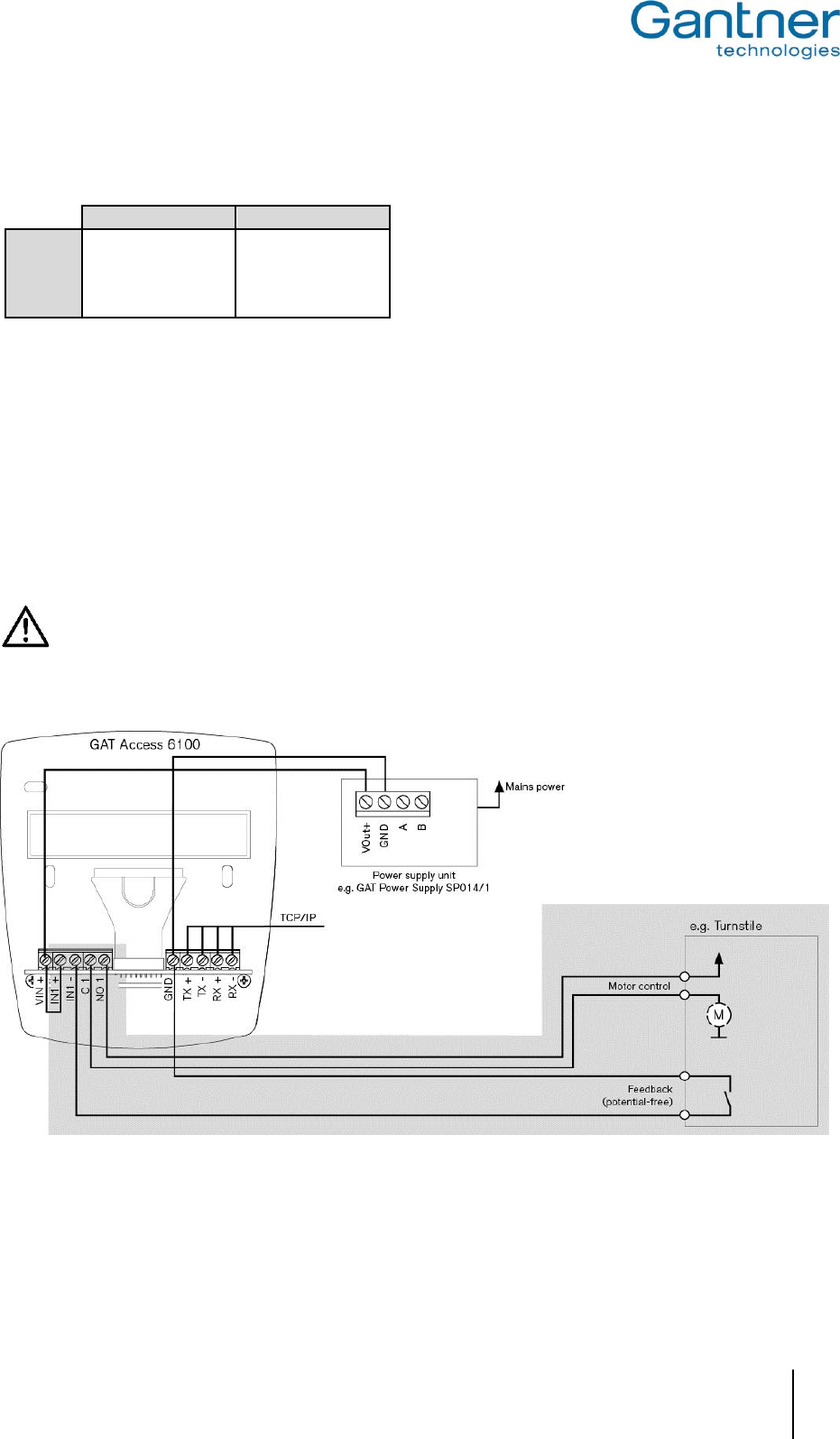
3.3 Connection to Turnstile or Door
The access terminals GAT Access 6100 have one relay output for unlocking of a turnstile or door and one
optocoupler input for status acquisition.
The output is a potential-free relay output and it must be connected to the corresponding control inputs at the
turnstile or door. The input is an optocoupler input and a corresponding supply voltage is required for switching the
input. The supply voltage can be taken from the GAT Access 6100 or supplied by another source.
Attention: Always pay attention to the max. permitted switching voltages and currents, as indicated in the
technical data (see "9. Technical Data").
The following figures show the wiring at the access terminals and the general connection to a turnstile. Please read
the documentation of the turnstile or door for more information about the electrical connections.
Figure 3.4 - Connection of GAT Access 6100 to a turnstile

GAT Access 6100, GAT Access 6100 F BIO, GAT Access 6100 F Enrollment Station, GAT TimeAxx 6150
Electrical Connections
30
HB_GAT-ACCESS6100--EN_12
www.gantner.com
3.4 Checklist for Final Installation
After installation and configuration fill-out the following checklist to ensure that every necessary step has been
performed and the GAT Access 6100 is ready to be put into operation.
Note: Some points in the Installation section are not necessary for the GAT Access 6100 Enrollment Station.
Installation:
Cable between device back part and upper part connected on both sides
Housing closed and sealed
Power supply connected
Interface connected
Host/server is running (for online mode)
RFID Reader tested (hold data carrier to scan field)
Configuration (see chapter "7. Configuration"):
Latest software is installed in the GAT Access 6100
Network parameters set (IP address, network name, subnet mask, DNS)
Time of GAT Access 6100 set correctly
Functional settings set (see chapter "4.3. Configuration Settings" and "GAT Config Manager" manual)
Site-key of the GAT Access 6100 is set correctly
GAT Access 6100, GAT Access 6100 F BIO, GAT Access 6100 F Enrollment Station, GAT TimeAxx 6150
Start-Up and Configuration
www.gantner.com
HB_GAT-ACCESS6100--EN_12
31
4. START-UP AND CONFIGURATION
The GAT Access 6100 terminals start automatically as soon as power supply is supplied. Generally, the different
types of GAT Access 6100 have the same start-up procedure.
For the configuration of the GAT Access 6100 it must be differentiated between system settings and functionality
settings. The system settings define the device setup like communication parameters and the functionality settings
define the operation of the device.
4.1 Starting the GAT Access 6100
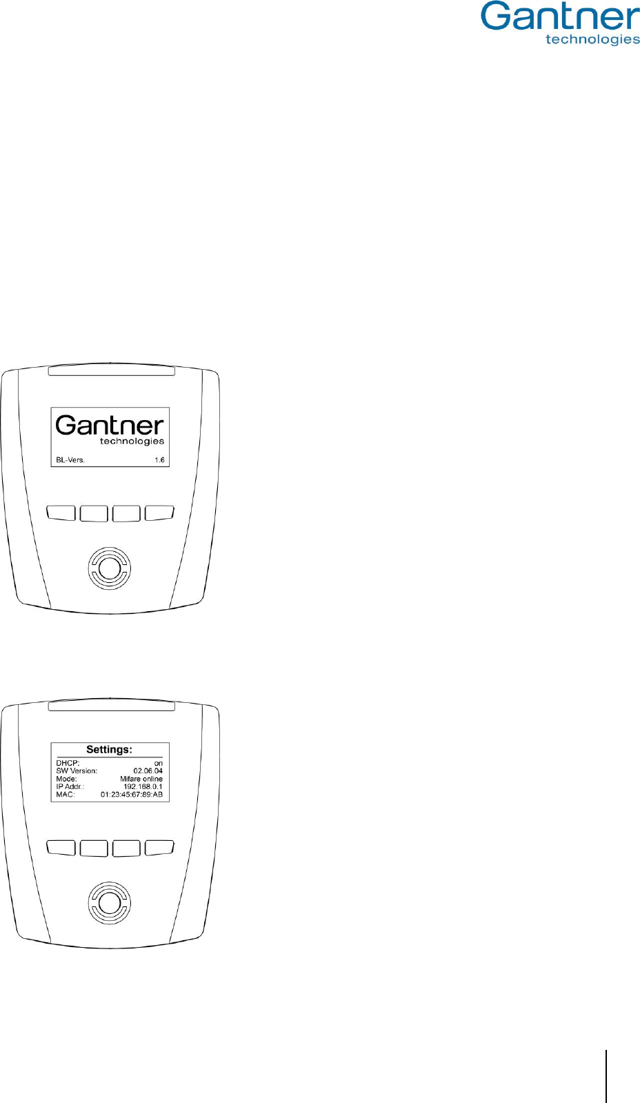
When connecting power the bootloader starts first. The GANTNER logo and the installed software version ("BL-
Vers.") is displayed and the LED status bar and the reader centre lights flash green and red alternately. The
terminal also checks for a connected network. These first steps can take about 1 minute.
Figure 4.1 - Start-up screen of GAT Access 6100
The display will turn blank and shortly after the terminal shows the current system settings on the display.
Figure 4.2 - System settings display during start-up
GAT Access 6100, GAT Access 6100 F BIO, GAT Access 6100 F Enrollment Station, GAT TimeAxx 6150
Start-Up and Configuration
32
HB_GAT-ACCESS6100--EN_12
www.gantner.com
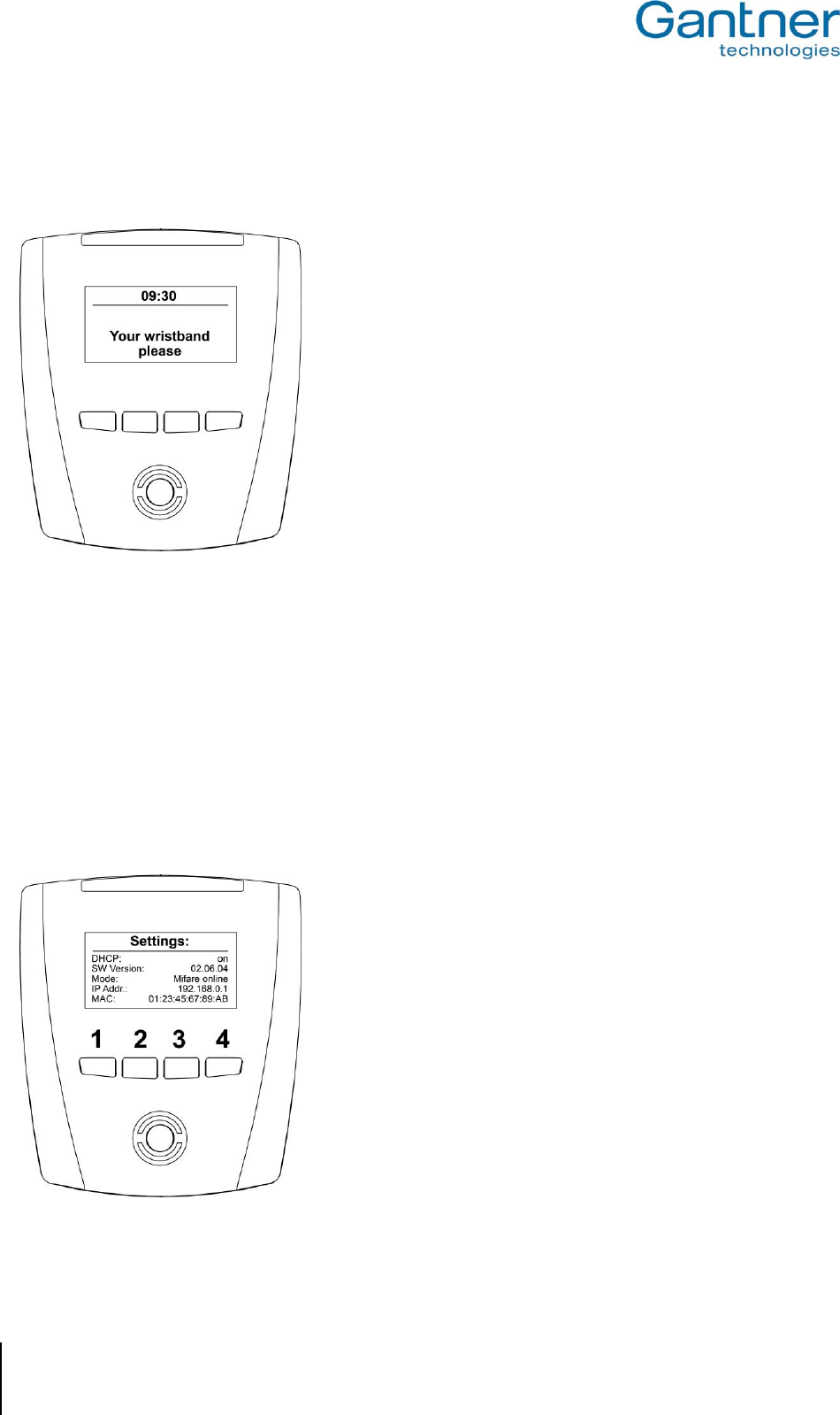
The system settings can be changed in the service menu (see "4.2.1. Service Menu of GAT Access 6100"). If the
service menu is not opened (i.e., if no action is performed at the terminal), the GAT Access 6100 continues to start
and then goes into idle mode. The main screen is displayed and the reading centre is flashing blue.
Figure 4.3 - Main screen (Example)
4.2 System Settings
The system settings of a GAT Access 6100 can be set on-site directly in in the service menu of the terminal or some
of these settings can also be defined via the network with the GAT Config Manager software.
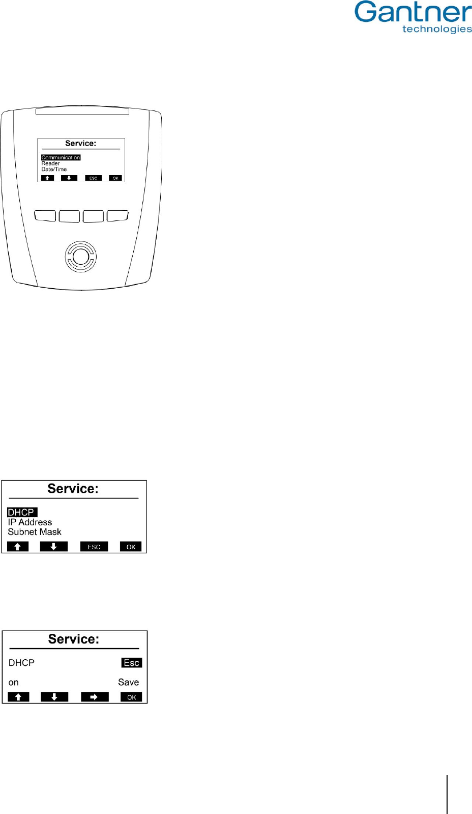
4.2.1 Service Menu of GAT Access 6100
The service menu can be accessed while the device settings (see Figure 4.2) are shown on the display during start-
up of the GAT Access 6100. While this display is shown, the function keys on the front of the GAT Access 6100
must be pressed in the following sequence: 1 - 1 - 4 - 4 - 2 - 3.
Figure 4.4 - Keys for activating the service menu
GAT Access 6100, GAT Access 6100 F BIO, GAT Access 6100 F Enrollment Station, GAT TimeAxx 6150
Start-Up and Configuration
www.gantner.com
HB_GAT-ACCESS6100--EN_12
33
The service menu will be shown:
Figure 4.5 - Service menu of GAT Access 6100
The navigation in the service menu is done by pressing the corresponding keys on the front. Generally on key 3 is
the "ESC" key and on key 4 is the "OK", which both can be used to return to the previous menu where "ESC" will
discard changes to the settings and "OK" will save made changes.
To leave the service menu press Key 3 ("ESC") and confirm the next screen with "Yes".
4.2.2 Communication Parameters
Select the menu item "Communication" in the service menu and press key 4 "OK". This brings up the
communication menu.
Figure 4.6 - Communication menu
When selecting a menu item and pressing "OK" the settings for the menu item are shown. As an example the
DHCP settings are shown.
Figure 4.7 - DHCP settings
GAT Access 6100, GAT Access 6100 F BIO, GAT Access 6100 F Enrollment Station, GAT TimeAxx 6150
Start-Up and Configuration
34
HB_GAT-ACCESS6100--EN_12
www.gantner.com
With the key 3 "" you can move the cursor (black background) to select the available options. Move the cursor to
"on" and then you can change between "on" and "off" with the keys 1 "" and 2 "". This principle works for all the
settings in the service menu.
The following settings can be made:
- DHCP: Set to "on" if a DHCP server is used in the network. In this case, the remaining settings (IP
address, subnet mask, gateway, DNS) will be set automatically by the DHCP server.
- IP Address: If no DHCP server is used for automatic IP assignment, enter the IP address of the GAT
Access 6100.
- Subnet Mask: Definition of the network prefix.
- Default Gateway: IP address of the default gateway.
- Primary DNS: IP address of the primary DNS (domain name server).
- Secondary DNS: IP address of the secondary DNS (domain name server).
- Device Name: Network name of the GAT Access 6100. Standard is "GA" + part number (6 digits) + serial
number (7 digits) of the device.
- MAC Address: The hardware MAC address of the GAT Access 6100. This cannot be changed.
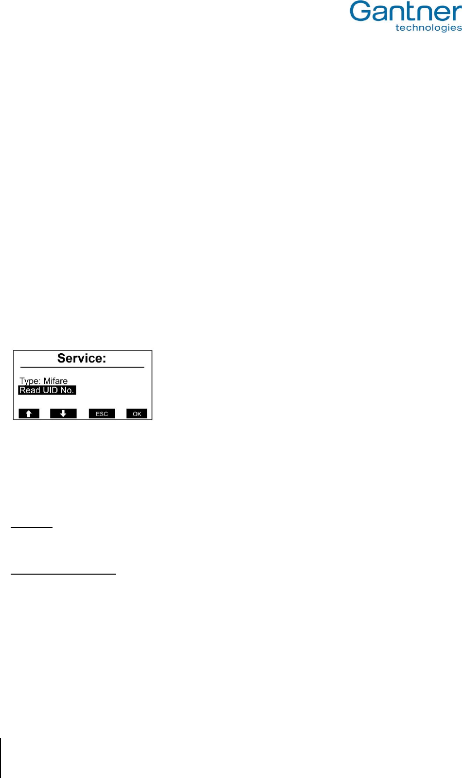
4.2.3 Reader Settings
Depending on the type of GAT Access 6100 different settings of the RFID reader can be displayed.
Figure 4.8 - Reader settings menu (MIFARE)
The RFID reader type of the GAT Access 6100 will be shown (here "Mifare"). The following functions are available
in this meu:
Read UID:
Via this menu, the unique number (UID) of a data carrier, held next to the reading field, is read and displayed.
Read/Clear Authorisation
These menu items are only shown for LEGIC® readers. With these functions it is possible to show / clear the
authorisation data stored in the internal LEGIC® reader.
GAT Access 6100, GAT Access 6100 F BIO, GAT Access 6100 F Enrollment Station, GAT TimeAxx 6150
Start-Up and Configuration
www.gantner.com
HB_GAT-ACCESS6100--EN_12
35
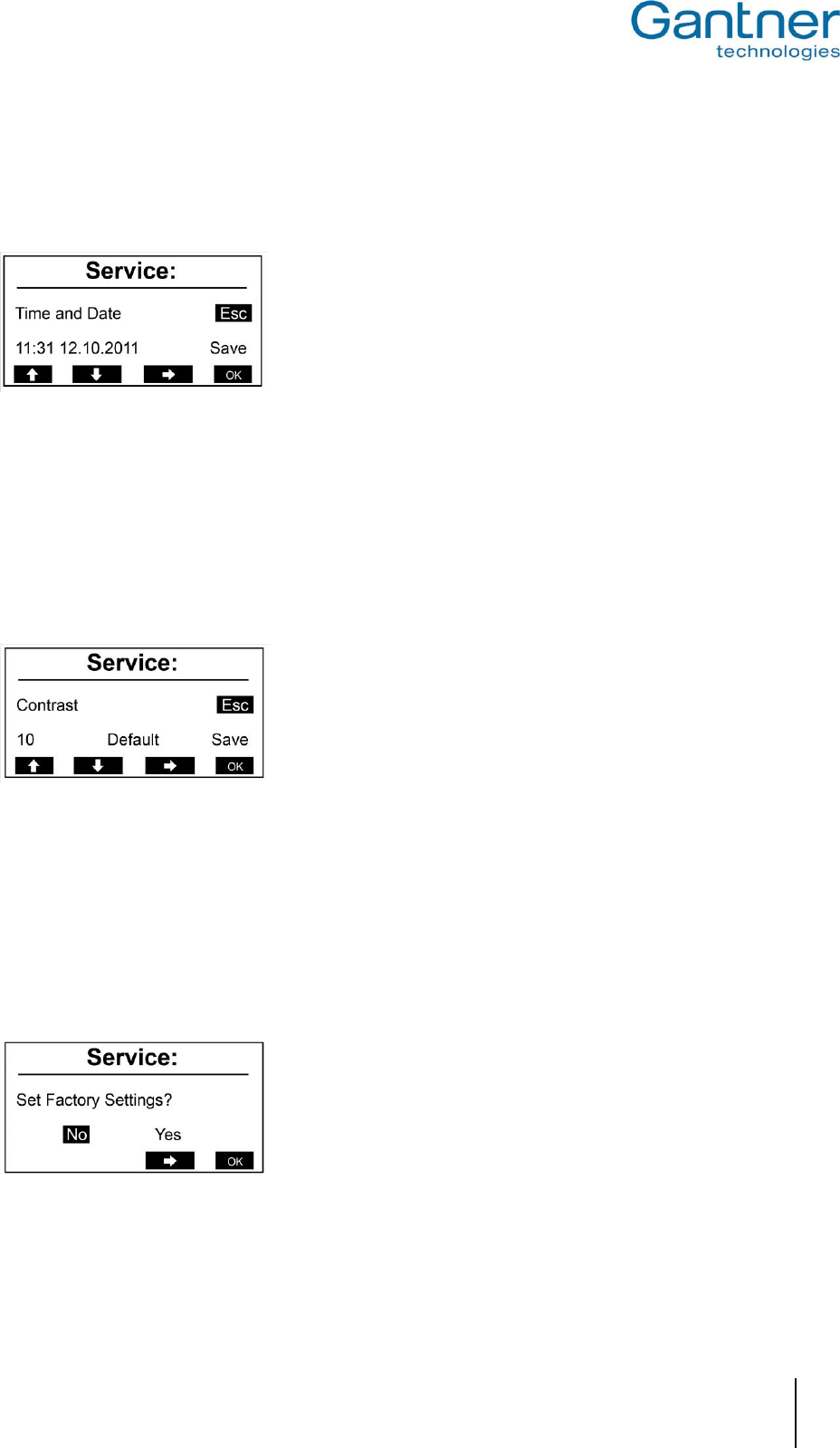
4.2.4 Date and Time Settings
During operation the GAT Access 6100 will show the current date and time on the display. It is important that these
are correct. To change the date and time select the menu item "Date/Time" in the service menu.
Figure 4.9 - Setting time and date of a GAT Access 6100
Select the places to change with the key 3 "" and change the number at the cursor position with the keys 1 ""
and 2 "". Confirm with key 4 "OK".
4.2.5 Display Contrast
You can change the contrast between the black and white parts of the display. Select "Display” and then the menu
item "Contrast".
Figure 4.10 - Setting the display contrast of a GAT Access 6100
Change to the contrast value with the key 3 "" and then change the number with the keys 1 "" and 2 "". The
set contrast can be seen directly while changing the contrast value. With "Default" the contrast value can be reset to
the default value. Confirm with key 4 "OK".
4.2.6 Restore Factory Settings
With the menu item "Factory Settings" it is possible to reset the system settings to the default settings on delivery.
Figure 4.11 - Factory Settings
Attention: After restoring factory settings, you must configure the TCP/IP communication parameters again in
order to be able to communicate with the GAT Access 6100.
GAT Access 6100, GAT Access 6100 F BIO, GAT Access 6100 F Enrollment Station, GAT TimeAxx 6150
Start-Up and Configuration
36
HB_GAT-ACCESS6100--EN_12
www.gantner.com
4.3 Configuration Settings
The configuration settings are the device functions that determine how the GAT Access 6100 interacts with the
user. These settings can be viewed and modified using "GAT Config Manager" PC software. This section provides
an overview on how to define the configuration settings with GAT Config Manager.
Note: A user guide is available when you install GAT Config Manager. This user guide contains detailed information
about the use and possibilities of this software.
In order to configure a GAT Access 6100 you must know the communication settings such as the IP address and
port number (default 8208) for TCP/IP configuration. To find this information see section "4.2. System Settings".
Configuration possibilities:
There are two ways you can configure a GAT Access 6100 with GAT Config Manager.
- Direct configuration: A connection to the GAT Access 6100 must be established by entering all the
communication settings required for a manual connection.
- Project configuration: Creating a project where the GAT Access 6100 and its communication settings are defined
once. To configure the GAT Access 6100, the connection to the device can then be
established by clicking the “Configure device” option in the project. One project can contain
several devices.
To begin configuring a device first start GAT Config Manager via the start menu within Windows®. The default
location of the software is "Programs > Gantner Electronic GmbH > GAT Config Manager".
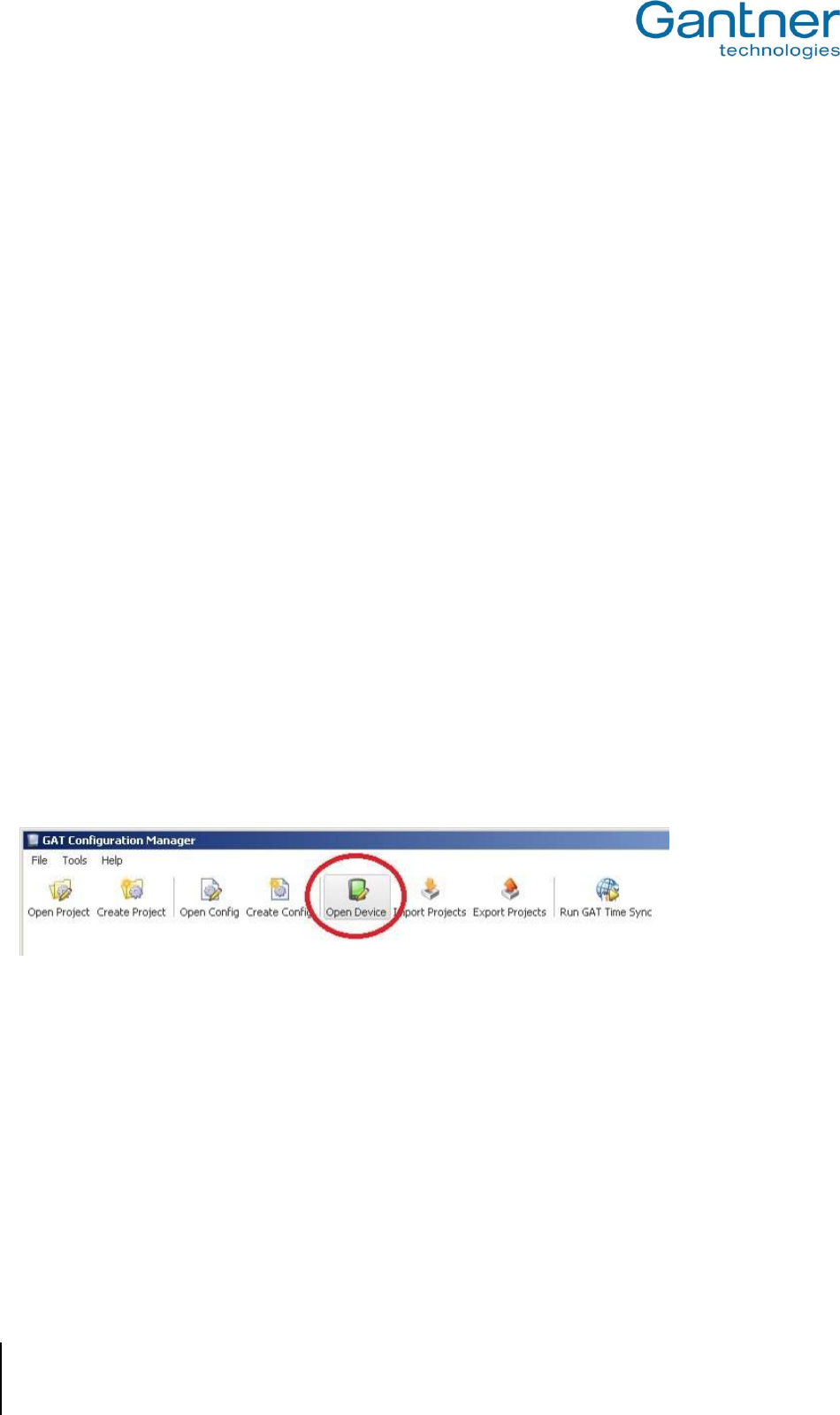
4.3.1 Direct Configuration
Once GAT Config Manager is open, complete the following steps to directly configure a GAT Access 6100.
Click on the "Open Device" icon at the top of the program.
o The device configuration wizard opens.
Figure 4.12 - Open device for direct configuration
The wizard requests the information required to access the GAT Access 6100. Go to the next page of the wizard
by clicking “Next”. To return to a previous page click “Previous” and to close the wizard click “Cancel”. The
"Finish" button becomes available when the wizard has received all the necessary information.
GAT Access 6100, GAT Access 6100 F BIO, GAT Access 6100 F Enrollment Station, GAT TimeAxx 6150
Start-Up and Configuration
www.gantner.com
HB_GAT-ACCESS6100--EN_12
37
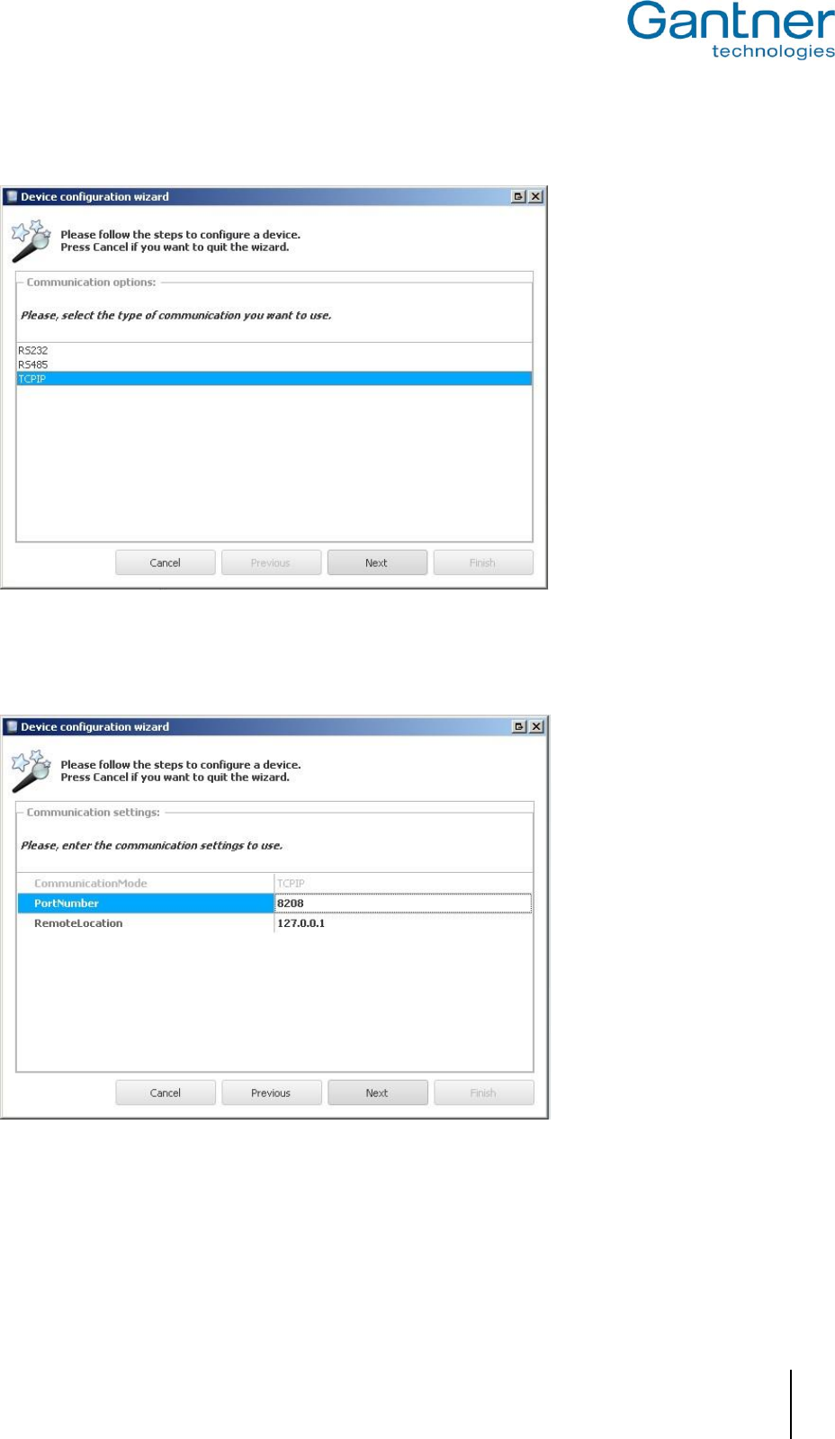
Select the communication type. Choose “TCPIP” then click “Next”.
Figure 4.13 - Open device for direct configuration (Wizard step 1)
Enter the IP address and port number of the GAT Access 6100 then click “Next”.
Figure 4.14 - Open device for direct configuration over TCP/IP (Wizard step 2)
GAT Access 6100, GAT Access 6100 F BIO, GAT Access 6100 F Enrollment Station, GAT TimeAxx 6150
Start-Up and Configuration
38
HB_GAT-ACCESS6100--EN_12
www.gantner.com
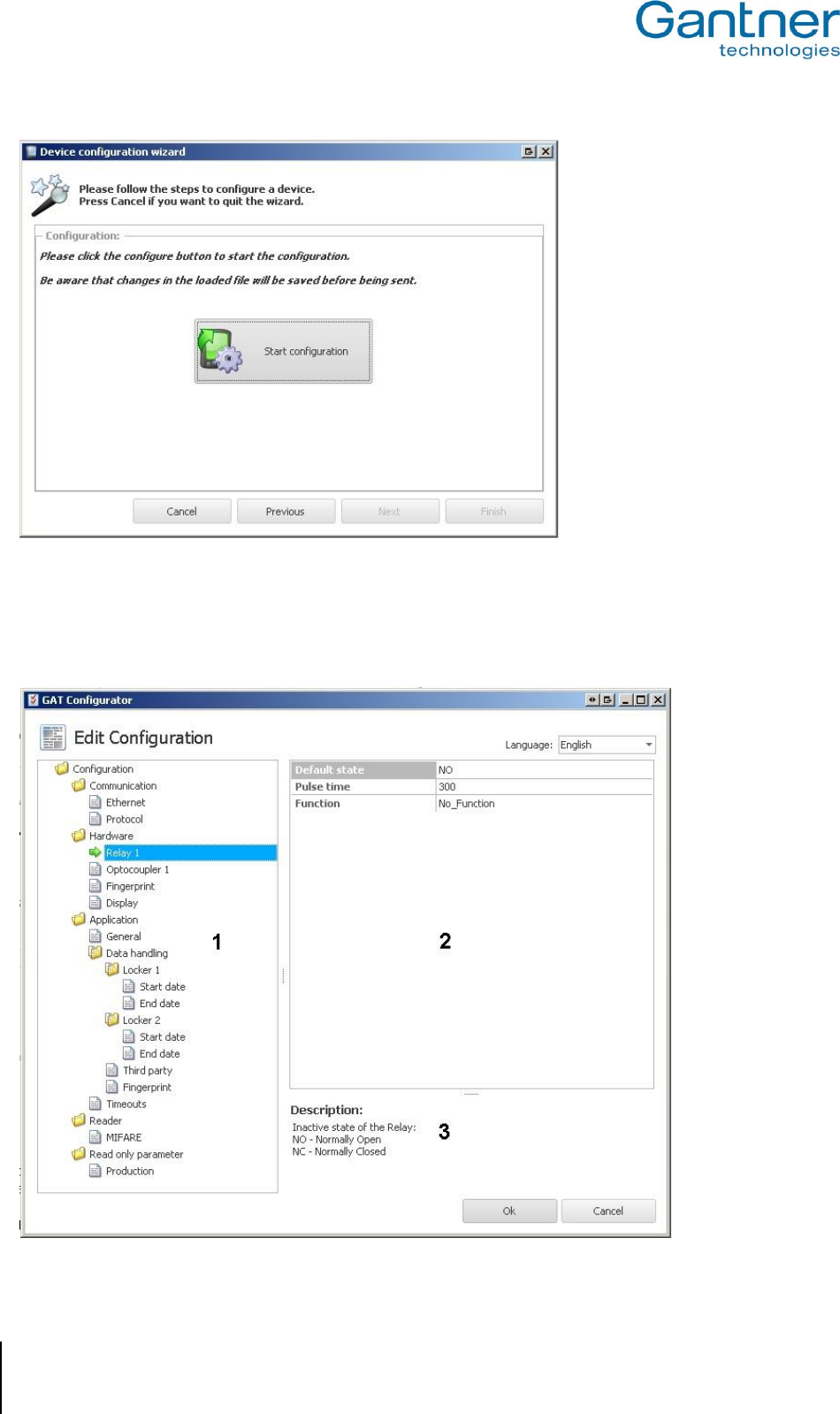
Figure 4.15 - Ready to start configuration (Wizard step 3)
Press "Start configuration".
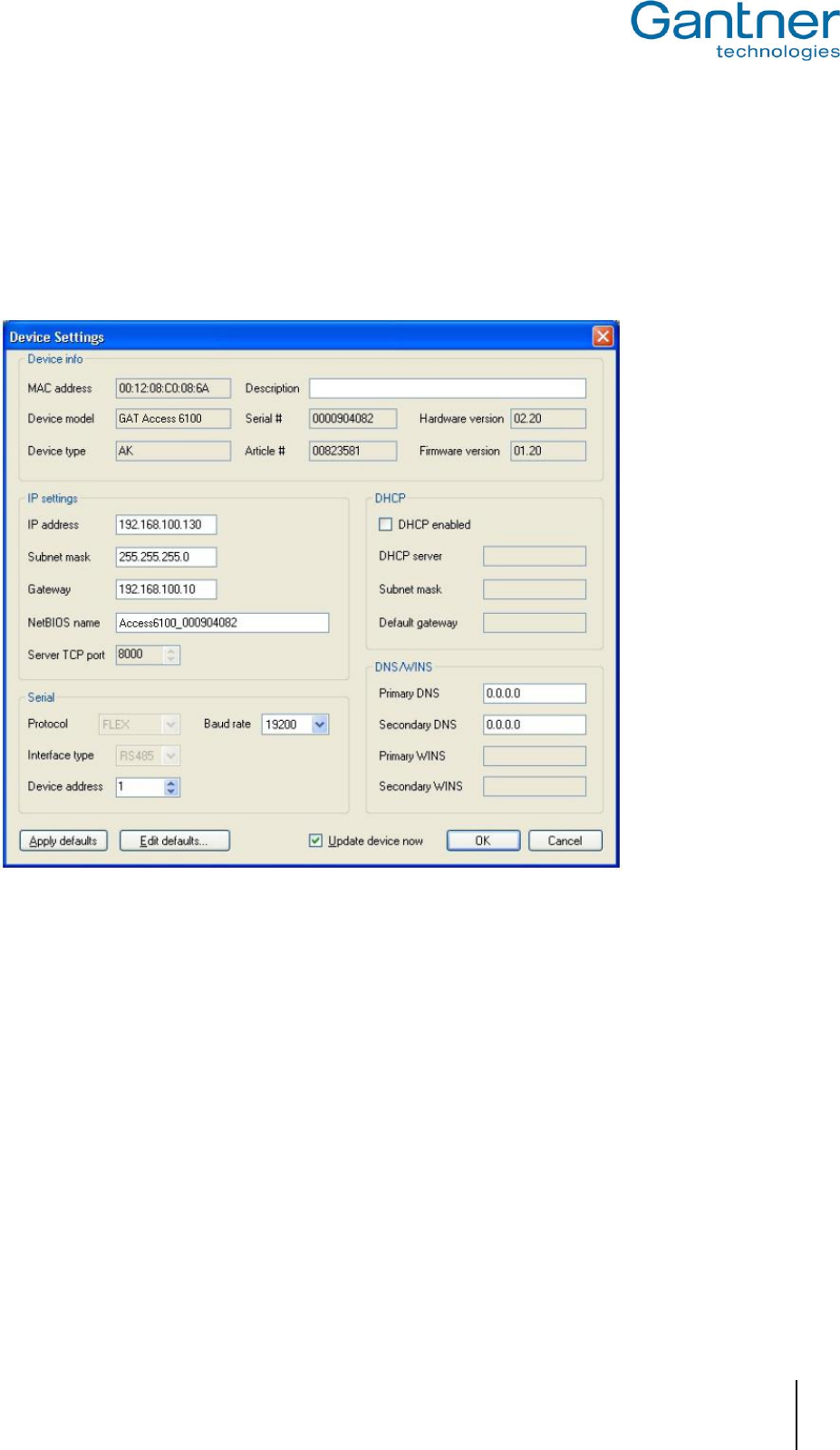
o GAT Config Manager will connect to the GAT Access 6100 and after a short pause, upload and display
the current configuration from the device.
Figure 4.16 - Configuration window for the GAT Access 6100
GAT Access 6100, GAT Access 6100 F BIO, GAT Access 6100 F Enrollment Station, GAT TimeAxx 6150
Start-Up and Configuration
www.gantner.com
HB_GAT-ACCESS6100--EN_12
39
The configuration settings of the GAT Access 6100 are organised into several categories. The directory on the left
(1) lists the different configuration categories. Click on a category and the settings for this category can be viewed
and adjusted in the field to the right (2). A short description of the setting is shown at the bottom of the window (3).
An overview of all the configuration settings is available in Table 4.1.
Note: A more detailed description of all available settings can be found in the GAT Config Manager manual.
4.3.2 Project Configuration
Complete the following steps to configure the GAT Access 6100 via a project in GAT Config Manager.
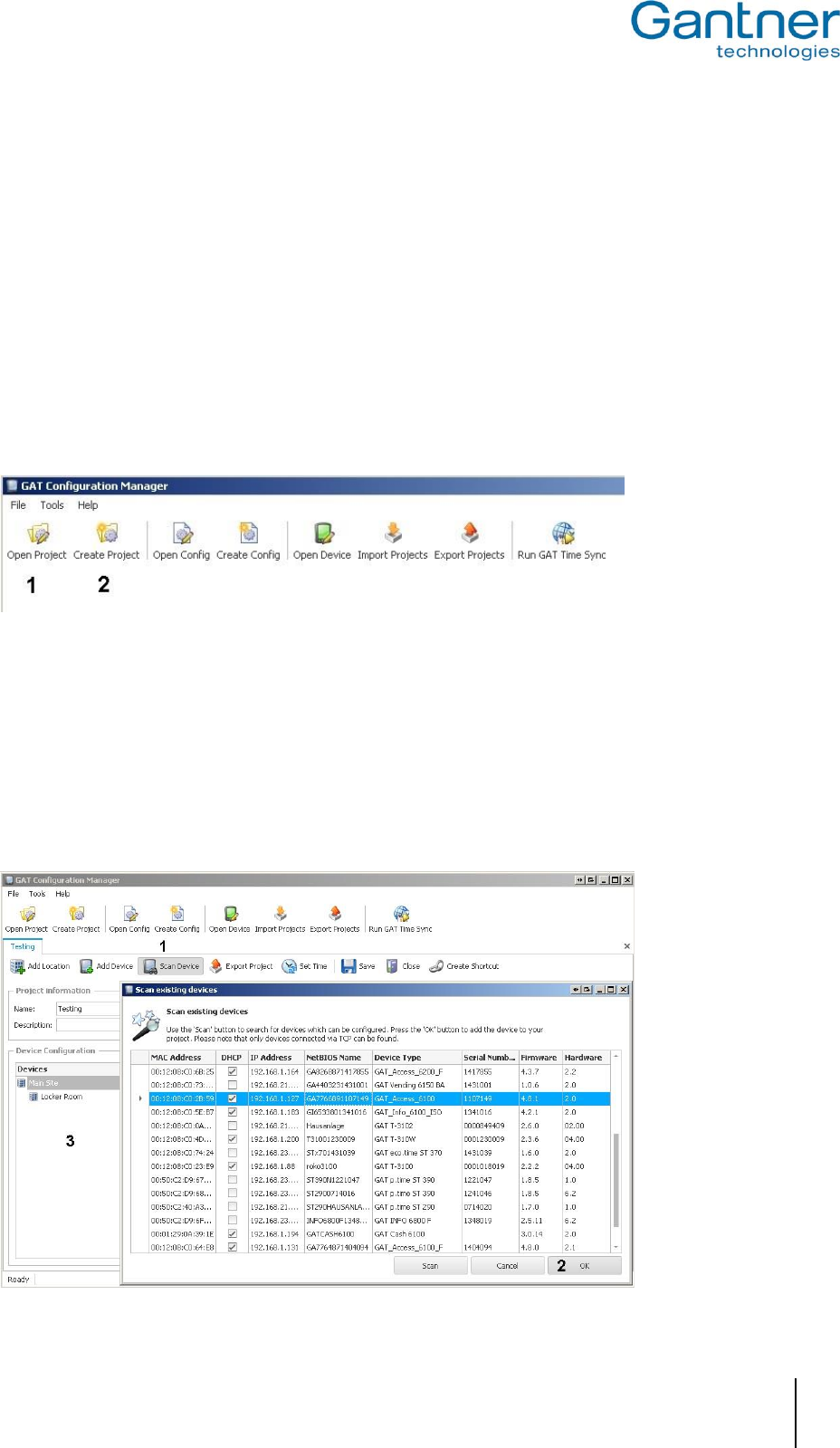
Click on the “Open Project” icon (1 in Figure 4.17) to find an existing project. Alternatively, click on the “Create
Project” icon (2 in Figure 4.17) to start a new project.
Figure 4.17 – GAT Config Manager - project setup
Once a project is established, click on the “Scan Device” icon (1 in Figure 4.18).
o The software scans the network and displays a list of all connected GANTNER devices.
Select your GAT Access 6100 from the list. Use device details such as the IP and MAC address to identify the
correct device.
o The selected device is highlighted in blue as shown in Figure 4.18.
Click on “OK” (2 in Figure 4.18).
o The selected device is added to the “Devices” list (3 in Figure 4.18).
GAT Access 6100, GAT Access 6100 F BIO, GAT Access 6100 F Enrollment Station, GAT TimeAxx 6150
Start-Up and Configuration
40
HB_GAT-ACCESS6100--EN_12
www.gantner.com
Figure 4.18 - Open a project for device configuration
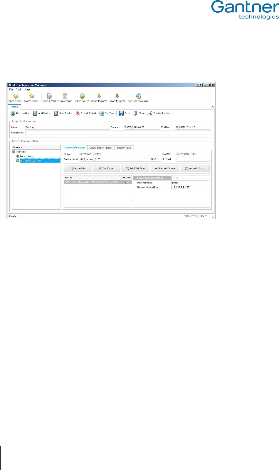
The main project window displays all the project information that has been entered into GAT Config Manager. Click
on the GAT Access 6100 in the “Devices” list and information about the selected device is shown to the right of the
project tree. Here you can view the predefined device and interface settings.
Figure 4.19 - Project window
To configure the display texts of the GAT Access 6100, click on the "Display Texts" tab. Here you can edit each
individual display text for the selected GAT Access 6100 (see "4.3.4. Display Texts").
To view and adjust the configuration settings of the GAT Access 6100 click on the "(2) Configure" button. The
existing configuration is uploaded from the GAT Access 6100 and displayed in the configuration window. See Figure
4.16 in the previous section for more information on the configuration window.
GAT Access 6100, GAT Access 6100 F BIO, GAT Access 6100 F Enrollment Station, GAT TimeAxx 6150
Start-Up and Configuration
www.gantner.com
HB_GAT-ACCESS6100--EN_12
41
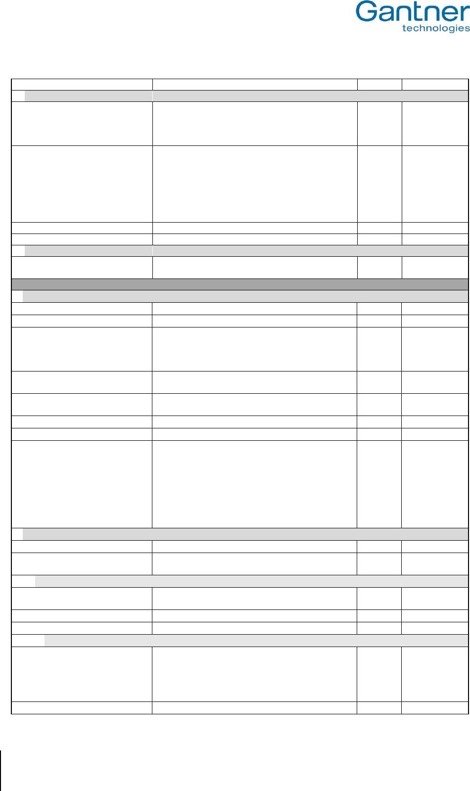
4.3.3 List of Configuration Settings
Table 4.1 lists all the configuration settings available for the GAT Access 6100 in GAT Config Manager. A brief
description and the format (where applicable) for each setting are shown in the table. Make sure to enter data in the
indicated format for settings such as time definitions, etc.
Options
Description
Format
Example(s)
Communication
Ethernet
Port number
Port used for communication with the device
8000
MAC address
The MAC address of the device (cannot be changed)
DHCP enabled
If enabled, will use the IP settings from a DCHP server
Static IP address
IP address of the device if DHCP is disabled
Static subnet mask
Subnet mask of the device (if DHCP is disabled)
Static primary DNS
Primary DNS address of the device (if DHCP disabled)
Static secondary DNS
Secondary DNS address of the device (if DHCP disabled)
Static default gateway
Default gateway of the device (if DHCP is disabled)
NetBIOS name
NetBIOS name of the GAT Access 6100
Dynamic IP address
IP address got from the DHCP Server
Dynamic subnet mask
Subnet mask got from the DHCP Server
Dynamic default gateway
Default gateway got from the DHCP Server
100 MBit Ethernet enabled
Enable 100 MBit Ethernet link, 10 MBit if disabled
Protocol
Terminal address
Address of the device
Integer
1 .. 255
Type
Protocol type
Text
Leisure
Communication mode
Operation mode of the device
Text
Online
Leisure Omron mode active
Indicate if OMRON mode for online communication is
enabled (MIFARE® and ISO 15693 data will be sent as
the old LEGIC® format).
Boolean
false
Button event enabled
Enable the button event command
Verify before CardIdent
Set if a verification with fingerprint is required before
CardIdent command is sent.
Boolean
false
Send Button Number
If this flag is enabled, the number of the pressed button
is transmitted in the "Button_Event" command.
Boolean
false
Hardware
Relay 1
Output for activation/unlocking of a turnstile or door
Default state
Inactive state of the Relay:
NO - Normally Open
NC - Normally Closed
NO / NC
Pulse time
Duration (ms) for how long the relay is active
300
Function
No function - Relay is not used
Entrance - Relay will be activated as configured in
'Pulse time'
ExternalLocking - Relay will be activated when a data
carrier was read by the reader, deactivated when the
process ends
No_Function /
Entrance /
External Locking
Optocoupler 1
Status input for feedback
Function
No function - Optocoupler is not used
Entrance - Feedback of an Entrance
External locking - Input for the locking of the terminal
Event trigger
An event is triggered if the Optocoupler input signal
matches the configured setting
Rising edge /
Falling edge /
Rising & falling e./
State high /
GAT Access 6100, GAT Access 6100 F BIO, GAT Access 6100 F Enrollment Station, GAT TimeAxx 6150
Start-Up and Configuration
42
HB_GAT-ACCESS6100--EN_12
www.gantner.com
State low
Fingerprint
Verification Level
Verification level of the finger print sensor. Can be set
between 0 and 10, the recommended value is 5. A
higher value decreases the false acceptances rate; a
lower value decreases the false rejections.
5
Mode Verification
Defines, how the finger print sensor is used:
Deactivated - Finger prints are not used
Data on Card - The finger prints of the users are stored
on their data carriers for verification.
Compatibility - If the host responds to the Card_Ident
Command with the state 0x00, the Verificationprocess
is started (Compatibility Mode)
Deactivated /
Data on Card /
Data on Data-
base /
Compatibility
Number Fingers
Number of different fingers usable for verification
2
Site key
Site key to read/write fingerprint data from data carriers
Display
Contrast
Contrast of the display. Can also be set in the service
menu of the device.
10
Application
General
Time format
Time format used to show time values at the device
Text
0 - 24 / AM / PM
Emergency Mode enabled
Enable the Emergency Mode
Boolean
True
Device Licence
Licence to enable special features of the device, for
example for the GAT Access 6100 F Upgrade (see
"4.4. Configuration of Offline Emergency Mode
for a GAT Access 6100 ").
Hex
4895CA89…
Enrollment Station
Indicates, if the licence activates the Enrollment Station
functionality
Boolean
false
Disable Secure UID
Indicates, if the licence is used to deactivate the
Secure UID
Boolean
false
Thirdparty Validation
Indicates, if the licence is used for third party validation
Boolean
false
Enable GAT Shower
Indicates, if the countdown functionality is activated
Boolean
false
Remaining period mode
Determines the action that will be performed after the
timeout during a remaining period break (see section
“Application” -> “Timeouts”) is exceeded.
Cancel: The countdown process will be cancelled
Continue Relay off: The countdown will proceed, the
relay will be switched off
Continue Relay on: The countdown will proceed, the
relay will be switched on
Cancel
Continue Relay
off
Continue Relay
on
Data handling
Deny if Checkin failed
Access denied if the LockerCheck-In fails
Boolean
false
Check validity date
Checks site number and validity date of data carriers,
when the GAT Access 6100 is in the Emergency Mode
Boolean
false
Locker 1
Read
Indicates, if data must be read from the first locker
segment of the data carriers.
Boolean
true
Position on card
Where the locker data 1 segment is located on data carriers
Integer
1 .. 255
Clear number
Clear the locker number from the data carrier.
Boolean
false
Start date
Mode
Selection of the LockerCheckin Mode for the Start Date
NONE: Value will not be changed
DELAY: Sets the start date to now + start date value
TIME: Sets the start date to today at start date value
FOREVER: Sets the start date to forever valid
Text
NONE / DELAY /
TIME / FOREVER
Hours
Hours of start date
Integer
0 .. 23
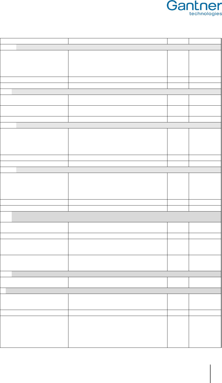
GAT Access 6100, GAT Access 6100 F BIO, GAT Access 6100 F Enrollment Station, GAT TimeAxx 6150
Start-Up and Configuration
www.gantner.com
HB_GAT-ACCESS6100--EN_12
43
Minutes
Minutes of start date
Integer
0 .. 59
End date
Mode
Selection of the LockerCheckin Mode for the End Date
NONE: Value will not be changed
DELAY: Sets the expiry date to now + expiry date value
TIME: Sets the expiry date to today at expiry date value
FOREVER: Sets the expiry date to forever valid
Text
NONE / DELAY /
TIME / FOREVER
Hours
Hours of end date
Integer
0 .. 23
Minutes
Minutes of end date
Integer
0 .. 59
Locker 2
Read
Indicates, if data must be read from the second locker
segment of data carriers.
Boolean
true
Position on card
Defines the segment where locker data 2 is located on
a data carrier
Integer
1 .. 255
Clear number
Clear the locker number from the data carrier.
Boolean
false
Start date
Mode
Selection of the LockerCheckin Mode for the Start Date
NONE: Value will not be changed
DELAY: Sets the start date to now + start date value
TIME: Sets the start date to today at start date value
FOREVER: Sets the start date to valid forever
Text
NONE / DELAY /
TIME / FOREVER
Hours
Hours of start date
Integer
0 .. 23
Minutes
Minutes of start date
Integer
0 .. 59
End date
Mode
Selection of the LockerCheckin Mode for the End Date
NONE: Value will not be changed
DELAY: Sets the expiry date to now + expiry date value
TIME: Sets the expiry date to today at expiry date value
FOREVER: Sets the expiry date to valid forever
Text
NONE / DELAY /
TIME / FOREVER
Hours
Hours of end date
Integer
0 .. 23
Minutes
Minutes of end date
Integer
0 .. 59
Third party (e.g. for GAT Access 6100 F Upgrade, see "4.4. Configuration of Offline Emergency Mode for a GAT
Access 6100 ")
Position on Card Base
Segment number of the third party segment on data
carriers
Integer
1
Block Number
Block number of the third party segment
Integer
0
Mask
The block, that is read from a data carrier, is logical AND
combined with this mask value and then compared with
the Result value
Hex
00000000FFFF
FFFF000…
Result
If the value, which results from logical AND combination of
the read block data from the data carrier and the Mask
value above, matches the Result value, access is granted
Hex
00000000AD33
6000…..
Fingerprint
Position on Card Base
Segment position of the finger print base sector on the
data carriers
Integer
6
Timeouts
Access allowed screen
Duration in milliseconds for the access allowed
process. For a GAT TimeAxx 6150 terminal, this
setting determines the countdown time.
Integer
12000
Access denied screen
Duration in milliseconds for the access denied process.
Integer
3000
Remaining period break
Only for Countdown Mode. Determines, how long the
user can pause the countdown of a GAT TimeAxx
6150 until the whole countdown process is cancelled
(input in milliseconds). The resulting action after
exceeding this timeout is determined by the setting
“Remaining period mode” in the “Application ->
Integer
60000
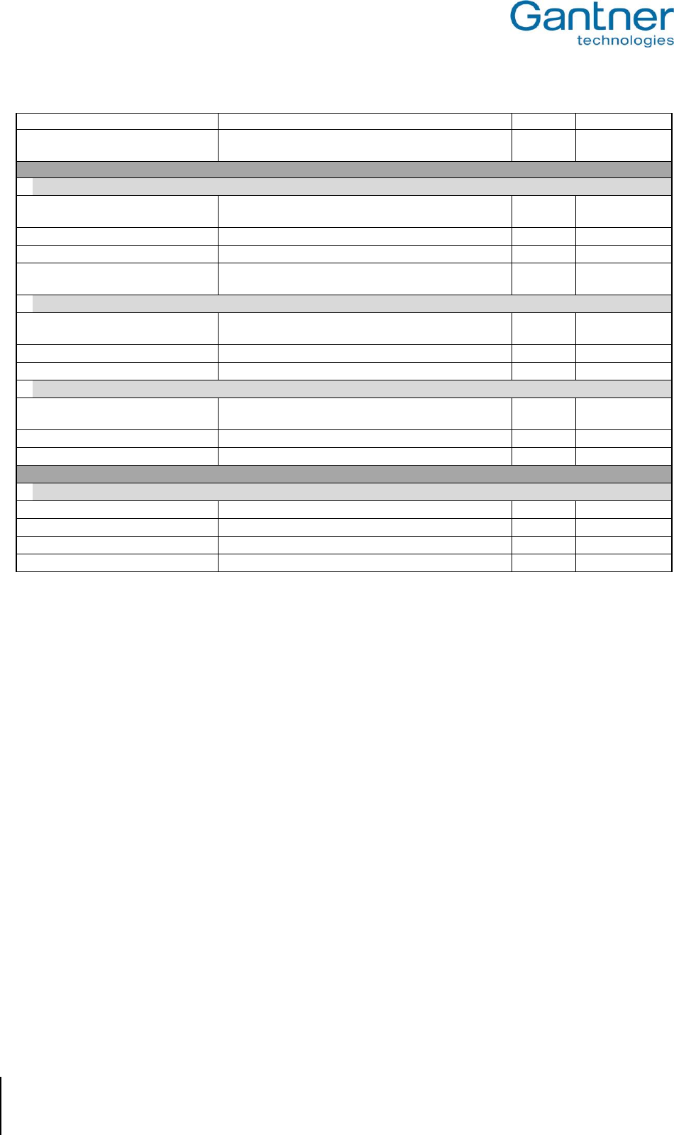
GAT Access 6100, GAT Access 6100 F BIO, GAT Access 6100 F Enrollment Station, GAT TimeAxx 6150
Start-Up and Configuration
44
HB_GAT-ACCESS6100--EN_12
www.gantner.com
General” section (see above).
Second Ident screen
Duration in milliseconds for the second identification
process.
Integer
3000
Reader
LEGIC
Options for reading of LEGIC® data carriers.
Site key
Site key of the device. All data carriers must have the
same site key to be used at the device.
Hex
9999
Subsite
Additional key for division of site keys.
Hex
00
Subsite enabled
If enabled the subsite keys of data carriers will be checked.
Boolean
false
Same segments structure
Set this to true, if all data carriers use the same segment
structure. Enables faster reading of data carriers.
Boolean
true
MIFARE
Options for reading of MIFARE® data carriers.
Site key
Site key of the device. All data carriers must have the
same site key to be used at the device.
Hex
73E0818B…
Subsite
Additional key for division of site keys.
Hex
00
Enable subsite
If enabled the subsite keys of data carriers are checked.
Boolean
false
ISO
Options for reading of ISO 15693 data carriers.
Site key
Site key of the device. All data carriers must have the
same site key to be used at the device.
Hex
73E0818B…
Subsite
Additional key for division of site keys.
Hex
00
Subsite enabled
If enabled the subsite keys of data carriers are checked.
Boolean
false
Read only parameter
Production
Production Data
Production data for the device (set at manufacturer)
Hardware Version
Hardware Version of the Device Hardware
Serial Number
Serial number of the device
Software Version
Software Version of the Application
Table 4.1 - Configuration options for GAT Access 6100
Note for online mode: If the host computer only requires the unique number of a data carrier, deleting all reading
options makes the process faster as the data carrier does not need to be read.
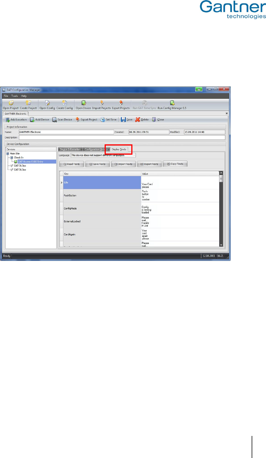
GAT Access 6100, GAT Access 6100 F BIO, GAT Access 6100 F Enrollment Station, GAT TimeAxx 6150
Start-Up and Configuration
www.gantner.com
HB_GAT-ACCESS6100--EN_12
45
4.3.4 Display Texts
The texts, which are shown on the display of a GAT Access 6100, can be edited in GAT Config Manager. In the
project window of a GAT Access 6100 (see Figure 4.19) go to the tab "Display Texts".
Figure 4.20 - Display text configuration
In the left column the type of text is indicated (information see below) and in the right column the text can be
entered. Each separate line of text is also shown on a separate line on the display. The maximum length of one text
line is 21 characters. If a line of text does not fit on the display of the GAT Access 6100 (using the standard font
size), the GAT Access 6100 automatically uses a smaller font size to display the entire text line.
The access terminals can only show signs of windows code page 1252 (Western European), 1251 (Cyrillic) and
1257 (Baltic). All other signs will be shown as "*" on the display.
Meaning of the texts:
- Idle: This text is shown during normal online operation mode to instruct users to hold their
data carrier next to the reading field.
- PushButton: Is shown if a key must be pressed by the user (Second Ident, answer from
Card_Ident status 240 - 255).
- ConfigMode: Is shown if the host computer is the communication master, e.g., if the configuration
is loaded from or to the GAT Access 6100.
- ExternalLocked: Is shown if an optocoupler input is defined as "Ext_Locking“ (external locking) and
this optocoupler is active and a user holds their data carrier to the reading field.

GAT Access 6100, GAT Access 6100 F BIO, GAT Access 6100 F Enrollment Station, GAT TimeAxx 6150
Start-Up and Configuration
46
HB_GAT-ACCESS6100--EN_12
www.gantner.com
- CardAgain: Is shown if the Locker Check-In is activated and a user removes their data carrier too
early from the reading field so that the locker data could not be deleted on the data
carrier yet.
- FeedbackLocked: Is shown if the connected turnstile is already turned and the user holds his data
carrier to the reading field, e.g. for entry or exit.
- Allow: Is shown if access is granted for a user.
- Denied: Is shown if access is denied for a user.
- OutOfService: Is shown if no communication is active with a host and the Online Emergency mode
is switched off (not used).
- RemoveCard: Is shown if the GAT Access 6100 reads the same data carrier twice or several times
without it being removed before. The data carrier must be removed from the reading
field.
- WaitPermission: Is shown while the GAT Access 6100 is waiting for a response from the host
computer after the terminal has read a data carrier and sent a request to the host.
- Default_Deny_01 ... _19: Depending on the status value of 1 up to 19 in the answer to a Card_Ident command
the corresponding display text will be shown and access is denied.
4.4 Configuration of Offline Emergency Mode for a GAT Access 6100
In the Offline Emergency mode it is possible to read data from any block within any sector of a data carrier. With a
configurable mask the read data can be separated into relevant and non-relevant data. The check for access
authorisation in this Offline Emergency mode is then done by comparing the relevant data with a predefined result
value. If the relevant data match exactly the defined result value, access is granted. Otherwise, access is denied.
To use the Offline Emergency mode the Offline Licence from GANTNER Electronic GmbH is required. To receive
this licence, the serial number and MAC address of the GAT Access 6100 must be sent to GANTNER in order to
generate the licence code. The licence code can then be entered into the GAT Access 6100 with the GAT Config
Manager. The following steps and figures show the configuration process for Offline Emergency Mode in GAT
Config Manager.
Note: For more information about GAT Config Manager, see chapter "4.3. Configuration Settings" or the manual of
the GAT Config Manager software.
1. A firmware with version 2.6.0 or higher must be installed in the GAT Access 6100. How to update the firmware
of a device is described in chapter "7. Updating the GAT ACCESS 6100".
2. In GAT Config Manager enter the Site Key information in the configuration option "Reader" -> "MIFARE" ->
"Site key" or "Reader" -> "LEGIC" -> "Site key" respectively.
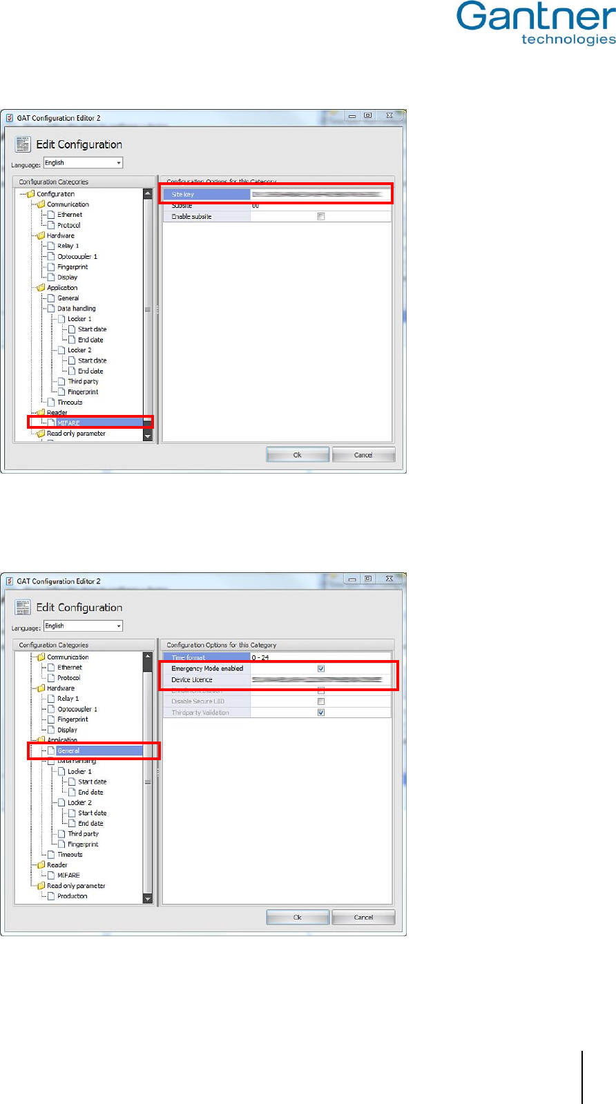
GAT Access 6100, GAT Access 6100 F BIO, GAT Access 6100 F Enrollment Station, GAT TimeAxx 6150
Start-Up and Configuration
www.gantner.com
HB_GAT-ACCESS6100--EN_12
47
3. Enter the Offline Licence number into the configuration option "Application" -> "General" -> "Device Licence".
4. The configuration option "Emergency Mode enabled" must also be checked.
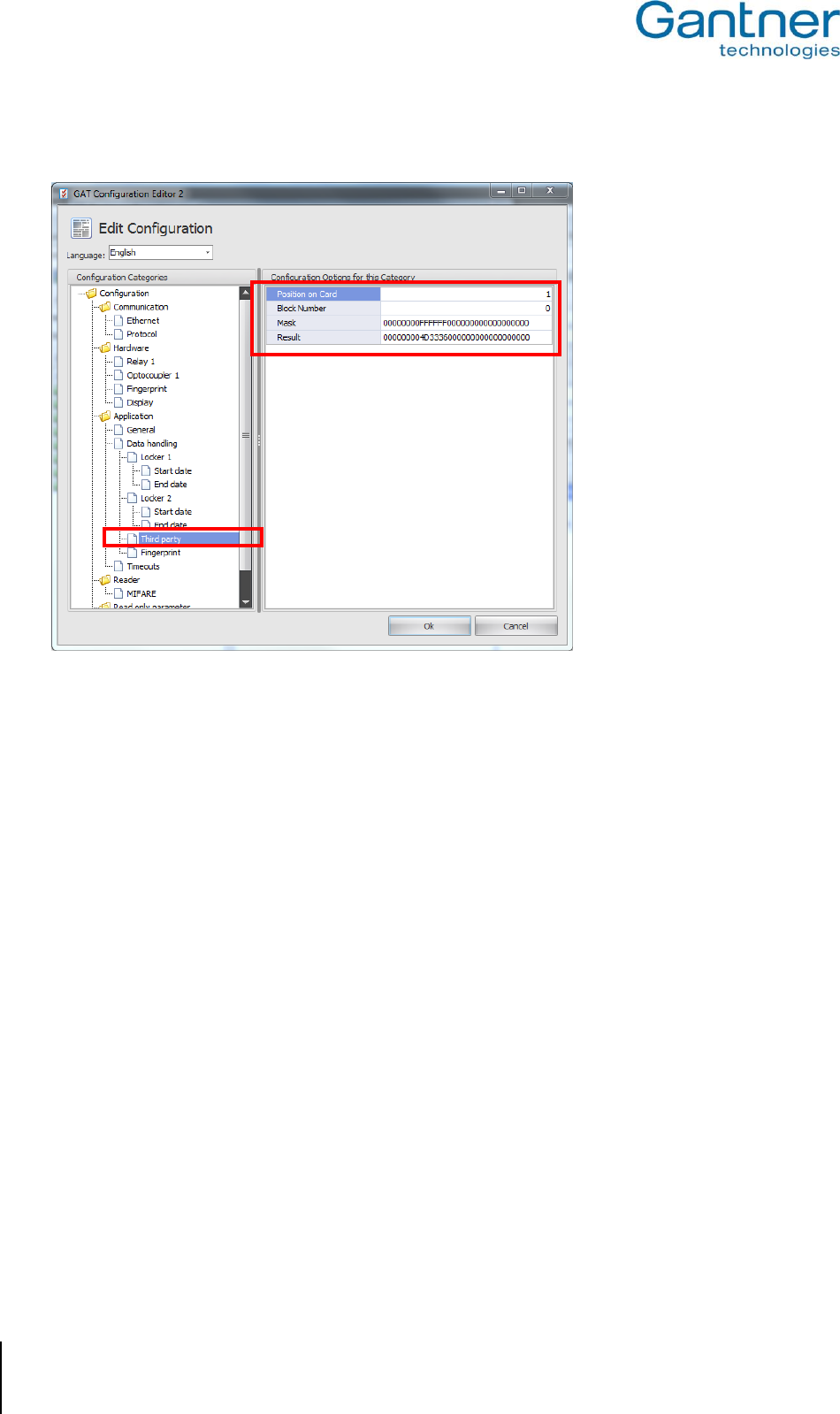
GAT Access 6100, GAT Access 6100 F BIO, GAT Access 6100 F Enrollment Station, GAT TimeAxx 6150
Start-Up and Configuration
48
HB_GAT-ACCESS6100--EN_12
www.gantner.com
5. Configure the "ThirdParty" data in the "Application" -> "Data handling" section as follows:
- Position on Card: Segement number of the user defined segment.
- Block Number: Number of the block of the user defined segment, which shall be read.
- Mask: The data, that are read from the data carrier from the defined block within the segment,
are combined with logical AND with this MASK value to dertermine, which value is
relevant for the compare with the Result value (see next field).
- Result: The result of the AND calculation of the read data and the Mask value are compared
with this Result value. If both values match, access is granted, else access is denied.
In the example above, the Mask value of "00000000FFFFFF000000…" means that the first 4 bytes of the read
data are not relevant (Mask value is entered in hex, i.e. 8 digits = 4 bytes with all bits set to "0") and then the
next 3 bytes are relevant ("FFFFFF" = 3 bytes with bits set to7 "1") and the following bytes are again not
relevant. This means that all data carriers, which have the information "M36” in ASCII or "4D3336" in hex value
at position 5 to 7 of the read data, have access permission.
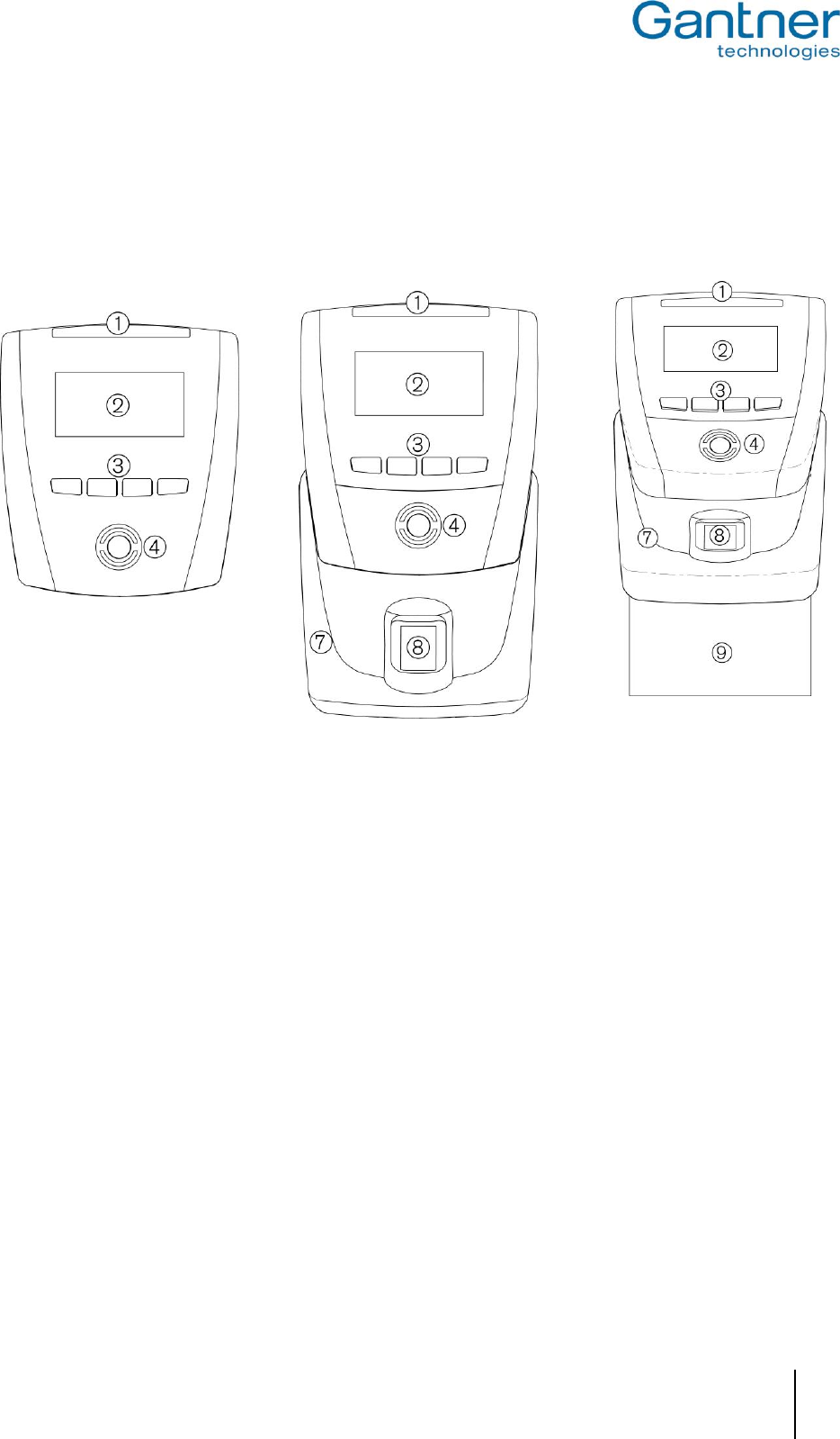
GAT Access 6100, GAT Access 6100 F BIO, GAT Access 6100 F Enrollment Station, GAT TimeAxx 6150
Operation
www.gantner.com
HB_GAT-ACCESS6100--EN_12
49
5. OPERATION
5.1 Control and Display Elements
GAT Access 6100 F Enrollment Station
GAT Access 6100 F BIO
GAT Access 6100
1 ... Four-segment LED display
2 ... Monochrome display (LCD)
3 ... Function keys
4 ... Illuminated, round scan field
8 ... Finger print sensor
Figure 5.1 - Control and display elements of the GAT Access 6100 terminals
Identification of people is done via RFID data carriers, which are read by holding them to the illuminated, round scan
fields (4) of the internal antenna. The light colour of the scan field changes accordingly, to indicate different status
information. Additional status information is shown by the 4-segment LED display above the display.
The GAT Access 6100 terminals also have a monochrome LC display to show user information. The display
language can be changed in the functionality settings (see "4.3. Configuration Settings").
For user input (e.g. to select certain functions or for acknowledgement) the GAT Access 6100 has four keys on the
front (3) to which different functions can be assigned. The assigned functions are shown on the display.
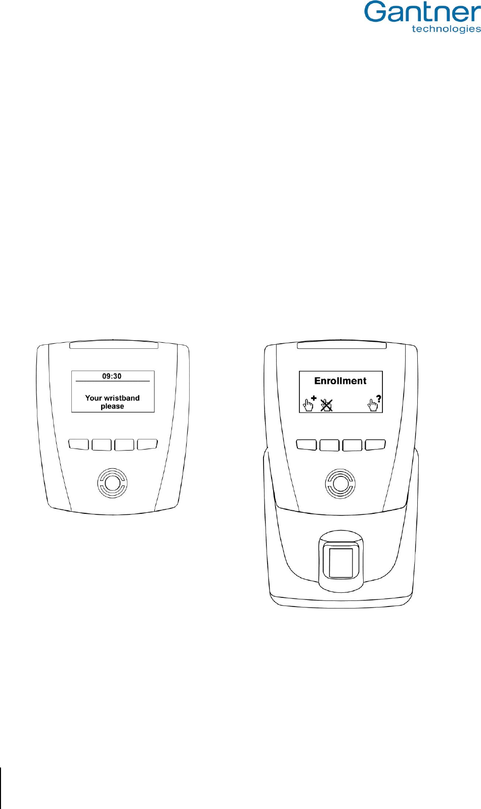
GAT Access 6100, GAT Access 6100 F BIO, GAT Access 6100 F Enrollment Station, GAT TimeAxx 6150
Operation
50
HB_GAT-ACCESS6100--EN_12
www.gantner.com
5.2 General
To use the GAT Access 6100 terminals the user must have an RFID data carrier (user-id) in the form of a card,
wristband or any other form. The data carriers must be of a supported technology:
- GAT Access 6100 B: LEGIC®
- GAT Access 6100 ISO: ISO 15693
- GAT Access 6100 F: MIFARE
- GAT Access 6100 F BIO: MIFARE
- GAT Access 6100 F Enrollment Station: MIFARE
- GAT TimeAxx 6150: MIFARE
In the normal operation mode the GAT Access 6100 show the start screen, asking for a data carrier (Figure 5.2).
The language to use for the display texts is set in the functionality settings (see "Configuration Settings"). The RFID
scan field flashes blue. The relay output is not activated.
The standard operating mode of a GAT Access 6100 Enrollment Station is the Offline Emergency Mode, where the
start screen looks like shown in Figure 5.3.
Figure 5.2 - Start screen of normal function mode of a Figure 5.3 - Start screen of normal function mode of a
GAT Access 6100, waiting for data carrier GAT Access 6100 F Enrollment Station in Offline Mode
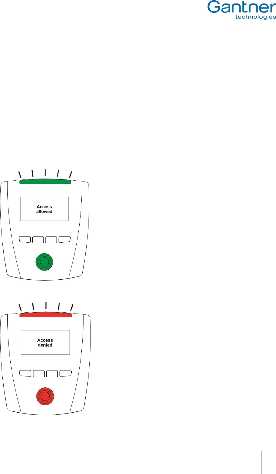
GAT Access 6100, GAT Access 6100 F BIO, GAT Access 6100 F Enrollment Station, GAT TimeAxx 6150
Operation
www.gantner.com
HB_GAT-ACCESS6100--EN_12
51
5.3 User Operation at a GAT Access 6100
To gain access to a restricted area, the user holds their data carrier next to the scan field. The data carrier must be
held steady in front of the scan field while the GAT Access 6100 reads the data carrier. Do not remove the data
carrier too early. First, the GAT Access 6100 checks the FID number (site number) on the data carrier. The FID of
the data carrier must be the same as the FID number of the terminal.
If the data carrier is valid (certificate, device licence, FID), the GAT Access 6100 sends the data carrier information
to the host for evaluation with the stored personnel data. If access to the restricted area is granted, a command is
sent to the GAT Access 6100 and the terminal will unlock the controlled door/turnstile for the configured time period.
The terminal indicates if access is granted or denied (see Figure 5.4 and Figure 5.5). Additionally, the four-segment
LED display and the RFID scan field illuminate green (access allowed) or red (access denied) with one (access
allowed) or two (access denied) acoustic signal(s) generated.
If the data carrier is invalid (e.g., not a GANTNER data carrier and certificate not deactivated via licence), access is
also denied without further checking.
Figure 5.4 - Information display after reading a data carrier (access granted - green lights)
Figure 5.5 - Information display after reading a data carrier (access denied - red lights)
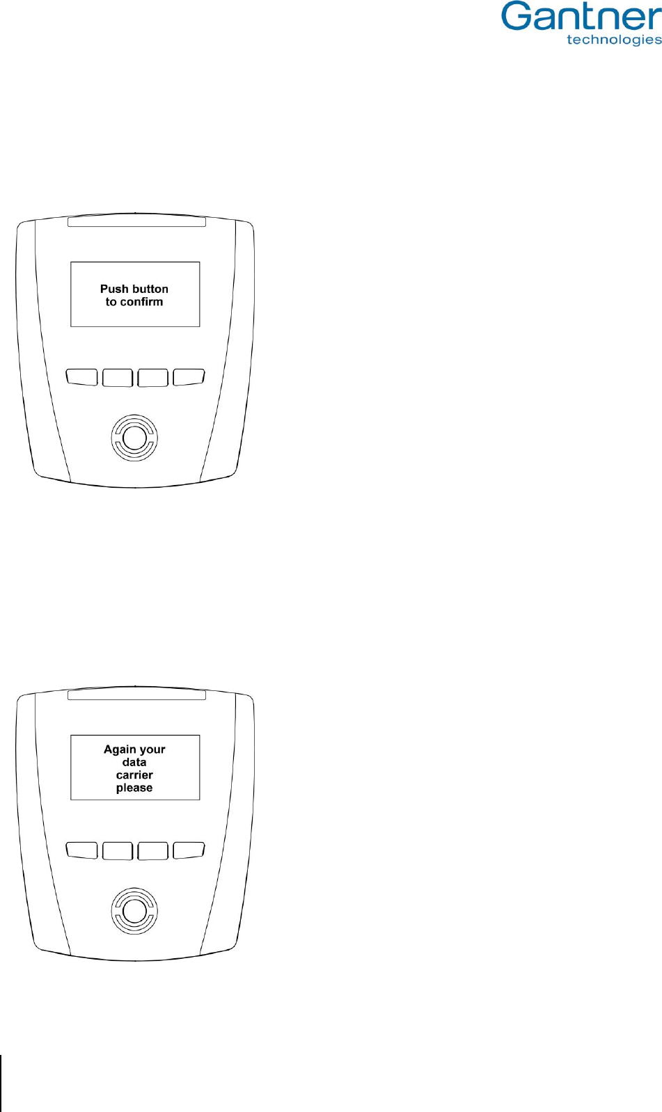
GAT Access 6100, GAT Access 6100 F BIO, GAT Access 6100 F Enrollment Station, GAT TimeAxx 6150
Operation
52
HB_GAT-ACCESS6100--EN_12
www.gantner.com
5.3.1 Additional Acknowledgment or Selection by the User
Depending on the configuration settings of a GAT Access 6100, the user may be requested to additionally press the
acknowledge key after the data carrier is read. In this case the terminal displays the text as shown in Figure 5.6, the
4-segment LED display flashes green and two acoustic signals are emitted.
Figure 5.6 - Information display if the user must press a key
The user must press one of the four keys below the display to gain access, otherwise access is denied.
5.3.2 Problem when Writing to the Data Carrier
If there was a problem when writing to the data carrier (e.g. with the Locker Check-In function), a GAT Access 6100
will show the following display (Figure 5.7). Reasons for this error may be that the data carrier was held not long
enough in front of the scan field or the data carrier is damaged.
Figure 5.7 - Problems when reading the data carrier

GAT Access 6100, GAT Access 6100 F BIO, GAT Access 6100 F Enrollment Station, GAT TimeAxx 6150
Operation
www.gantner.com
HB_GAT-ACCESS6100--EN_12
53
5.4 User Operation at a GAT Access 6100 F BIO
The GAT Access 6100 F BIO has the same functionality as the GAT Access 6100 terminals (see "5.3. User
Operation at a GAT Access 6100"). The GAT Access 6100 F BIO provides the additional function of identifying
visitors by their fingerprints in addition to data carrier verification. The process for this is described below.
To enable fingerprint verification, the visitors must first scan their fingerprints. The enrollment station can be
configured to record either one or two fingerprints directly onto the visitor‘s data carrier. Recording two fingerprints
ensures a visitor can still gain access in instances where one fingerprint may not be readable due to an injury for
example. Depending on the configuration, fingerprints must be scanned once time or twice. This is done with the
GAT Access 6100 F Enrollment Station, e.g. at the check-in. The scanned fingerprints are stored onto the personnel
data carriers of the visitors.
Attention: The finger prints are only stored on the data carriers of the visitors and never in a terminal, the
Enrollment Station or on a PC/Server.
The fingerprint verification can also be deactivated again for a data carrier at the Enrollment Station.
When a visitor identifies himself at a GAT Access 6100 F BIO with his data carrier and the fingerprint verification is
active, the terminal asks him to put one of the fingers, which are stored on his data carrier, onto the sensor field of
the finger print reader. Only if the scanned fingerprint matches one of the fingerprints on the data carrier the further
authorisation process is performed. Otherwise, access is denied.
Note: The fingerprint verification function can be used, for example, for season tickets and provides security
against the misuse of lost data carriers. Since the fingerprint data on the data carrier is checked with each
visit, a lost data carrier cannot be used by another person.
5.5 User Operation at a GAT Access 6100 F Enrollment Station
The GAT Access 6100 F Enrollment Station is used to scan and store up to two finger prints of the visitors onto their
personnel data carriers in order to verify the data carriers when the visitors make an identification (see also "5.4.
User Operation at a GAT Access 6100 F BIO" for more information about the verification process).
Attention: The finger prints are only stored on the data carriers of the visitors and never in the Enrollment Station,
a terminal or on a PC/Server.
The Enrollment Station can be used in Online and Offline mode.
A detailed operational description of the Enrollment Station is available as a separate document. The following lines
give a short description about the user operation.
5.5.1 Enrol Fingerprints at the Enrollment Station
The enrollment station can be configured to record either one or two fingerprints directly onto the visitor‘s data
carrier. Recording two fingerprints ensures a visitor can still gain access in instances where one fingerprint may not
be readable due to an injury for example
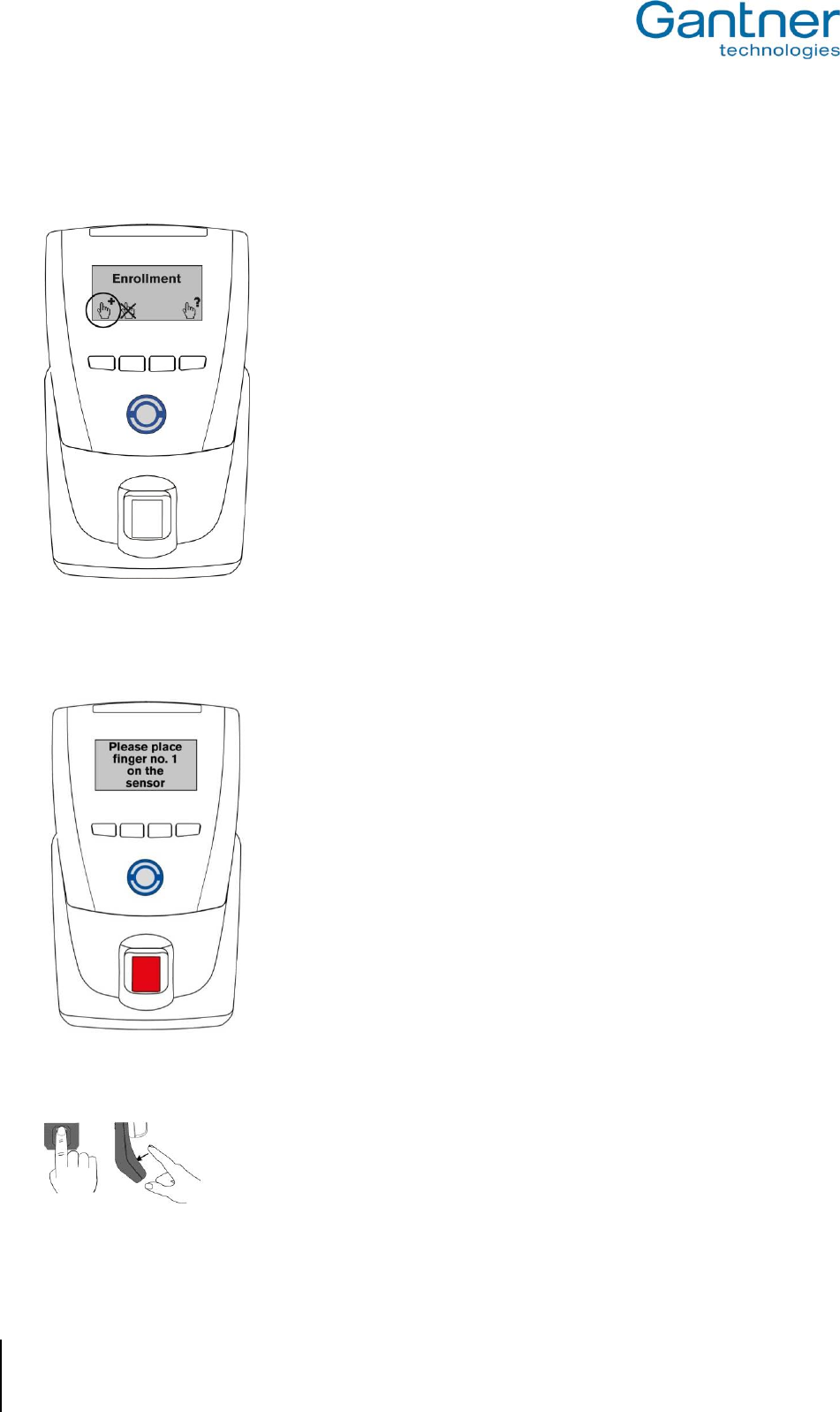
GAT Access 6100, GAT Access 6100 F BIO, GAT Access 6100 F Enrollment Station, GAT TimeAxx 6150
Operation
54
HB_GAT-ACCESS6100--EN_12
www.gantner.com
Complete the following steps to record a visitor’s fingerprints:
1. If the Enrollment Station is in Offline mode, the following screen is shown.
Press the left button to begin enrollment and continue with step 2. In Online mode this screen is not shown and
you can begin directly with step 2.
2. Hold the visitor‘s data carrier next to the RFID scan field of the Enrollment Station.
First, the display will briefly show "Enrollment" and then invite the visitor to put the first finger
on the sensor.
The RFID scan field illuminates in blue and the fingerprint sensor in red.
3. Remove the data carrier from the RFID scan field.
4. The visitor must place their first finger onto the sensor.
Note: The finger must be placed vertically, centred and gently onto the sensor.
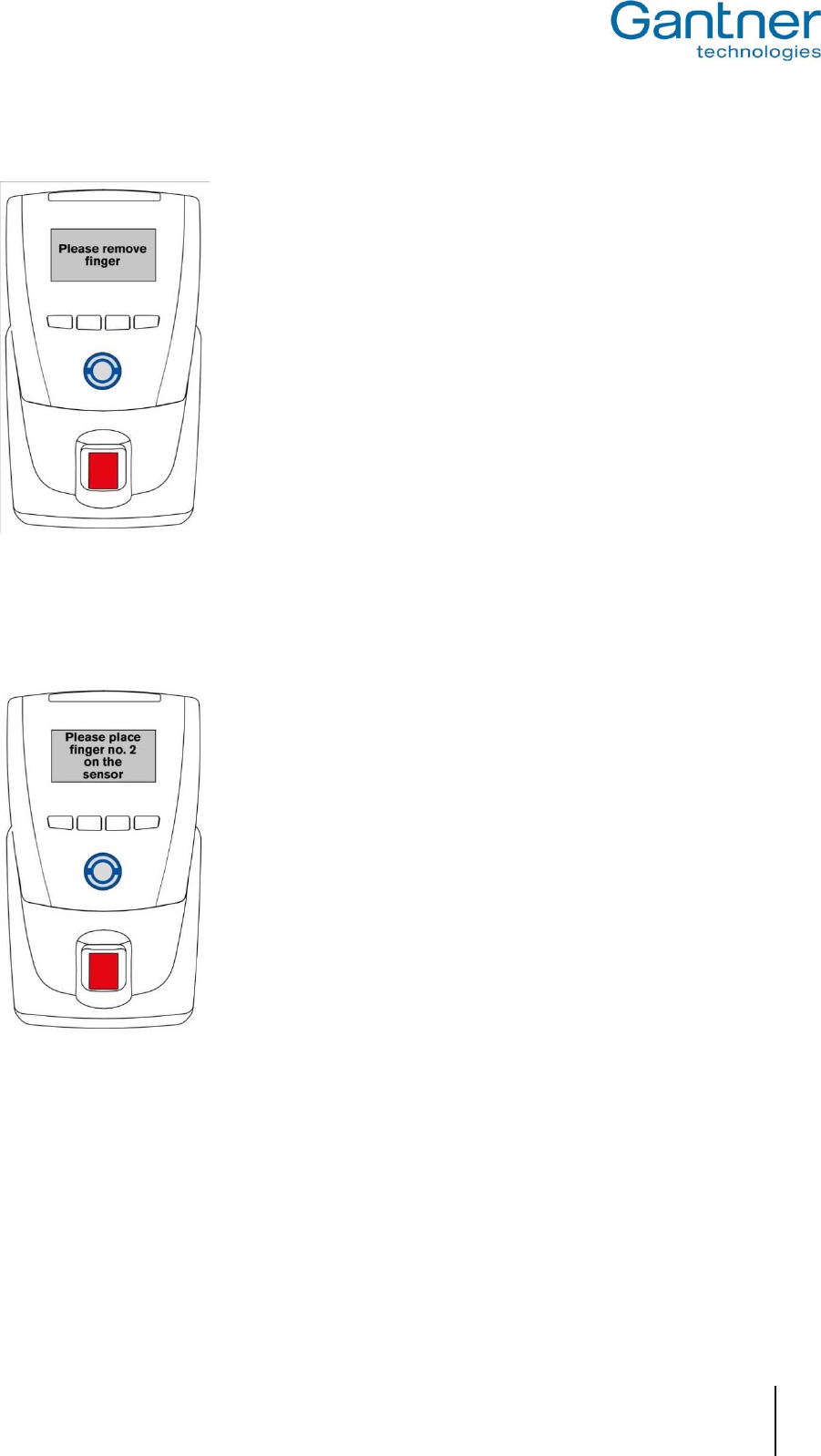
GAT Access 6100, GAT Access 6100 F BIO, GAT Access 6100 F Enrollment Station, GAT TimeAxx 6150
Operation
www.gantner.com
HB_GAT-ACCESS6100--EN_12
55
If the fingerprint was scanned correctly, the display shows a message instructing
the visitor to remove their finger from the sensor.
If the fingerprint was not scanned correctly, a corresponding message is
displayed.
Note: The fingerprint sensor should be regularly cleaned (see 5.5.4. Cleaning the
Fingerprint Sensor).
5. Once the fingerprint has been correctly scanned, the visitor must remove their finger from the sensor and
repeat step 3 using the same finger. The fingerprint must be scanned correctly 3 times to ensure reliable data.
6. Depending on the terminal configuration, the enrollment station may ask to scan a second fingerprint. Proceed
to step 8 otherwise.
Invitation to scan the second fingerprint.
7. Repeat steps 3 and 4 using the second finger. The second fingerprint must also be scanned correctly three
times.
8. Once the fingerprint data is recorded by the terminal, the data carrier must be read once more to save the data
onto the data carrier.
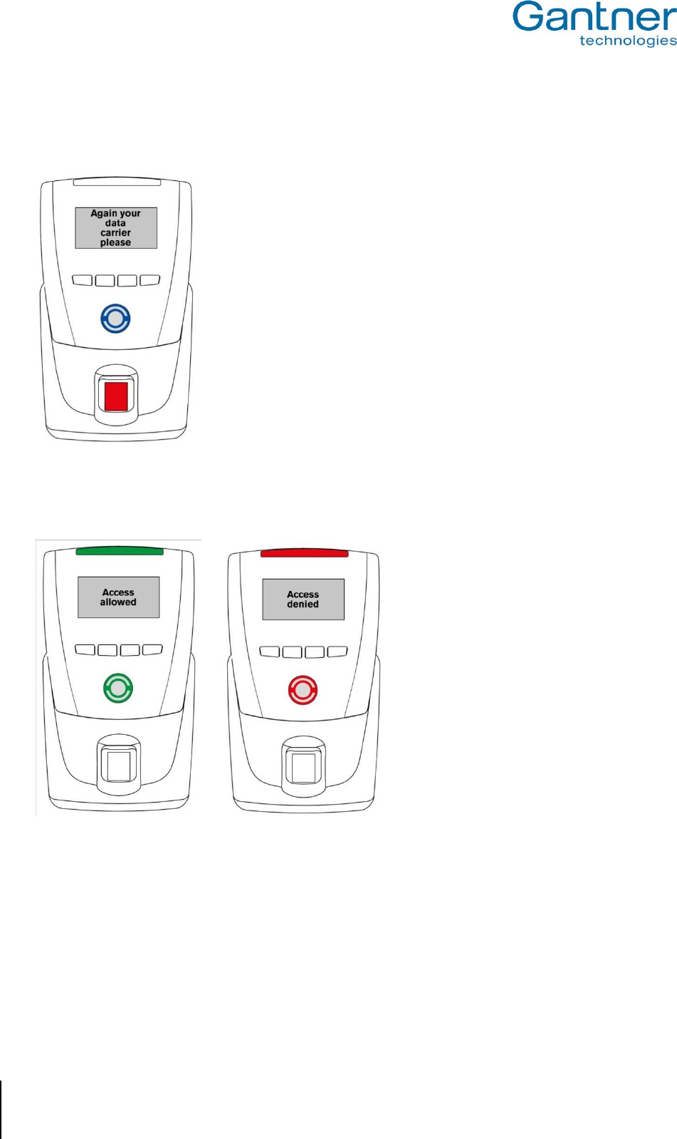
GAT Access 6100, GAT Access 6100 F BIO, GAT Access 6100 F Enrollment Station, GAT TimeAxx 6150
Operation
56
HB_GAT-ACCESS6100--EN_12
www.gantner.com
Request for data carrier.
9. Hold the user‘s data carrier next to RFID scan field within 3 seconds. The fingerprint data is written onto the data
carrier and a message is displayed to confirm if the action was successful or not:
Writing successful Error - writing not successful
Attention: As mentioned above, the fingerprint data is only stored on the visitor’s personal data carrier and never
in the terminal or on a PC/Server.
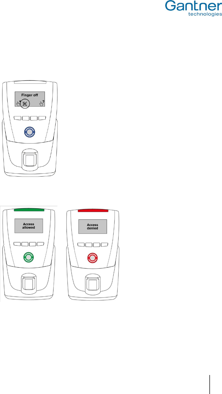
GAT Access 6100, GAT Access 6100 F BIO, GAT Access 6100 F Enrollment Station, GAT TimeAxx 6150
Operation
www.gantner.com
HB_GAT-ACCESS6100--EN_12
57
5.5.2 Deactivation of the Fingerprint Verification
With a GAT Access 6100 F Enrollment Station in Offline mode the fingerprint verification for the visitor is
deactivated. Access will then be possible with the data carrier alone, without the need to scan the fingerprint.
1. Press the second button on the Enrollment Station. The display shows the message “Finger off”.
2. Hold the data carrier of the visitor to the RFID scan field. The fingerprints are deleted on the data carrier and the
fingerprint verification will be deactivated. After 1 second the result is shown as follows:
Deleting successful Error - deleting not successful
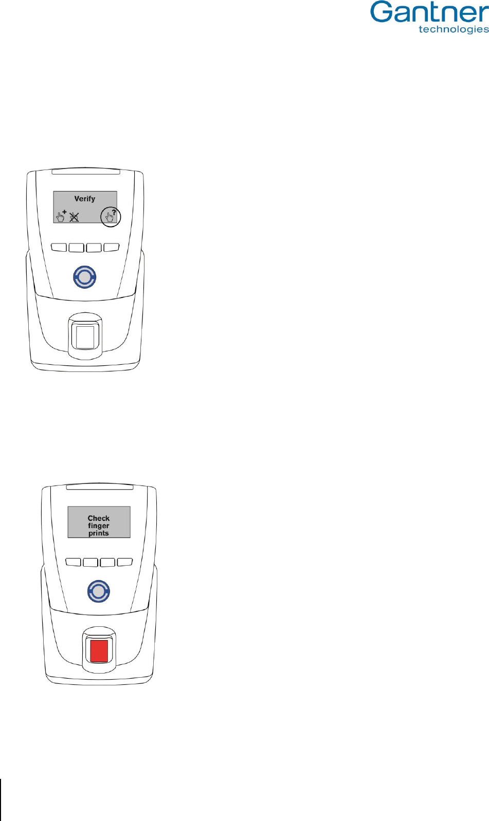
GAT Access 6100, GAT Access 6100 F BIO, GAT Access 6100 F Enrollment Station, GAT TimeAxx 6150
Operation
58
HB_GAT-ACCESS6100--EN_12
www.gantner.com
5.5.3 Verifying the Functionality of a Data Carrier
Complete the following steps to check the access functionality of a data carrier and/or the quality of the fingerprint
data at a GAT Access 6100 F Enrollment Station.
1. Press button four. The “Verify” message is shown on the display.
2. Depending on whether there is fingerprint data stored on the data carrier or not, the following two options are
possible:
a) No fingerprint data saved on data carrier:
Hold the data carrier next to the RFID reading field. The data carrier’s access status will be signalled as
shown in point 3.
b) Fingerprint data saved on data carrier:
Hold the data carrier next to the RFID reading field. The following display is shown:
The visitor must now place one of their previously recorded fingers onto the sensor.
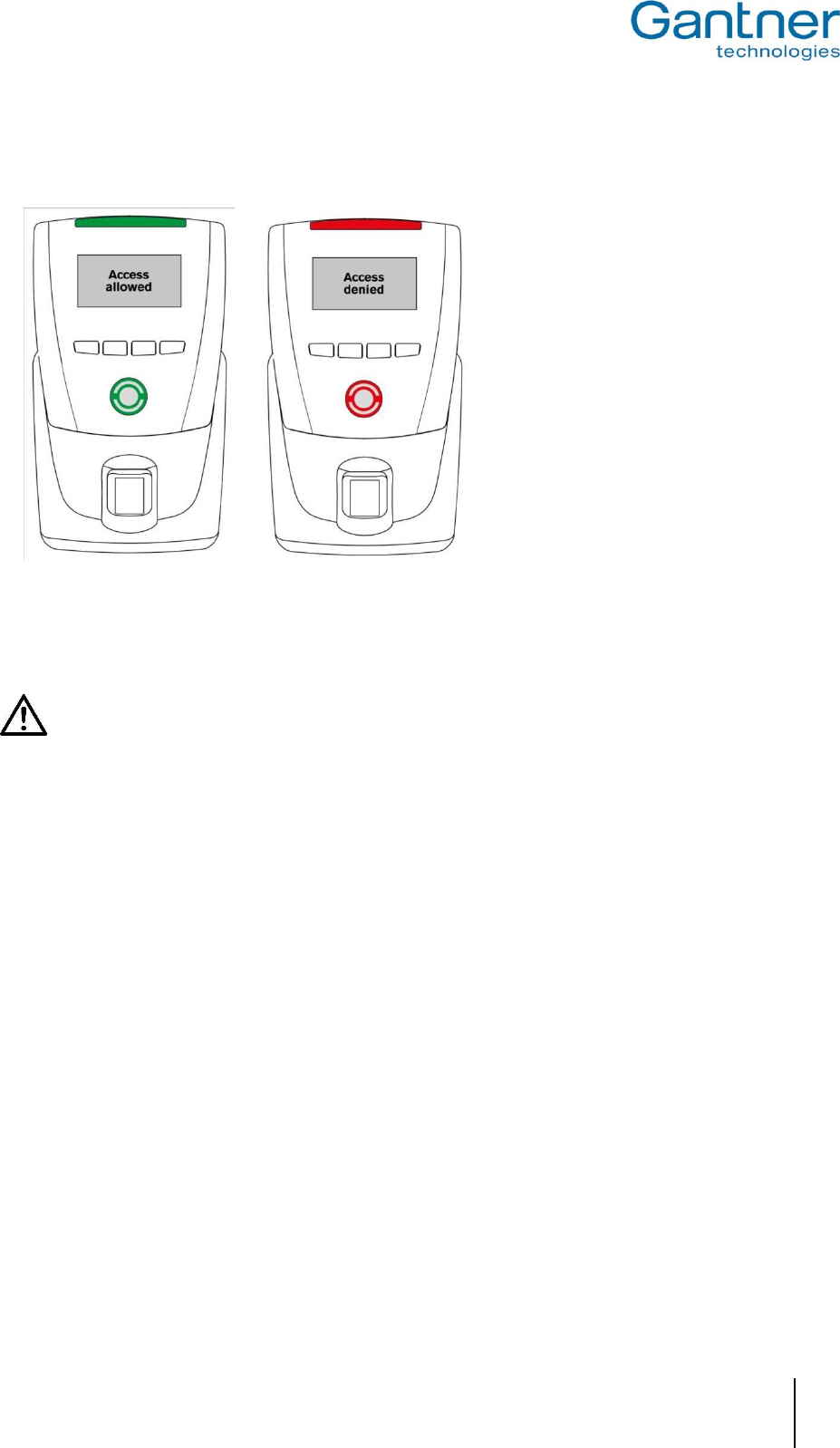
GAT Access 6100, GAT Access 6100 F BIO, GAT Access 6100 F Enrollment Station, GAT TimeAxx 6150
Operation
www.gantner.com
HB_GAT-ACCESS6100--EN_12
59
3. The result of the data carrier check is indicated by the enrollment station as follows:
Verification successful Error - Verification not successful
5.5.4 Cleaning the Fingerprint Sensor
The sensor surface should be regularly cleaned to guarantee a distinct and secure finger print identification.
Attention: To clean the sensor use a damp (not wet!), soft cloth. Never use corrosive cleaning agents or
sharp tools.
5.6 Standard Operation for the GAT TimeAxx 6150 with Countdown Functionality
Using its relay output and the necessary cabling connections, the GAT TimeAxx 6150 with countdown functionality
can control external equipment such as a shower or a sunbed, depending on the user’s authorisation. When the
user has valid authorisation the GAT TimeAxx 6150 will activate the equipment for a pre-defined time period.
In idle mode the equipment is turned-off, the GAT TimeAxx 6150 displays a configurable message (see Figure 5.8)
and the 4-segment LED bar shines green to indicate that the equipment is available for use.
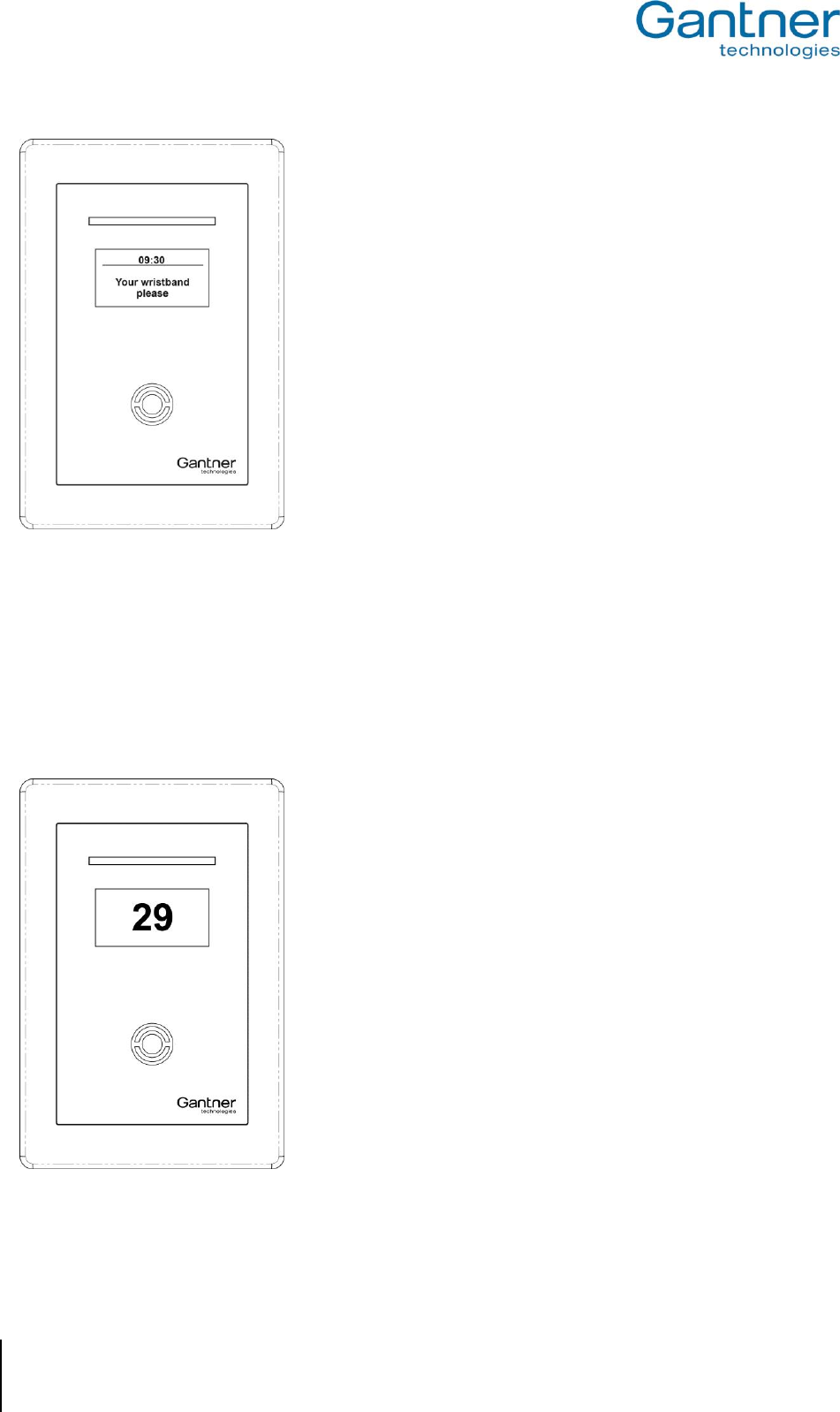
GAT Access 6100, GAT Access 6100 F BIO, GAT Access 6100 F Enrollment Station, GAT TimeAxx 6150
Operation
60
HB_GAT-ACCESS6100--EN_12
www.gantner.com
Figure 5.8 - Information display of GAT TimeAxx 6150 in idle state
In order to activate the equipment, the user holds their data carrier next to the terminal’s scan field. The terminal
sends the user’s data to a server that checks the authorisation of the user. Depending on the system configuration,
a fee can be applied for using the equipment. When configured as such the corresponding amount is debited from
the user’s account on the server.
Following the authorisation and account debiting process, the GAT TimeAxx 6150 activates the equipment and
starts the countdown. The terminal displays the remaining time to use the equipment and the 4-segment LED
display shines red to indicate that the equipment is currently in use.
Figure 5.9 - Indication of the remaining time to use the equipment
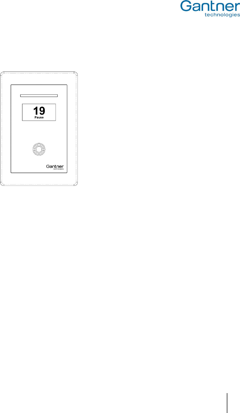
GAT Access 6100, GAT Access 6100 F BIO, GAT Access 6100 F Enrollment Station, GAT TimeAxx 6150
Operation
www.gantner.com
HB_GAT-ACCESS6100--EN_12
61
The GAT TimeAxx 6150 can be configured to allow the user to pause the equipment. If this function is active, the
user holds their data carrier next to the scan field while the equipment is turned-on and the terminal will turn-off the
equipment and pause the countdown. The display indicates the paused state.
Figure 5.10 - Pausing the equipment
To reactivate the equipment the user again holds their data carrier next to the scan field.
Note: In the configuration it is also possible to enable pausing of the countdown via the digital optocoupler input.
This allows the user to pause the equipment by pressing a button that is connected to the optocoupler input
of the GAT TimeAxx 6150.
When in pause mode it is possible to stop/cancel the countdown process before the configured runtime has ended.
For this functionality the correct timeout and action must be set in the configuration (see in chapter "4.3.3. List of
Configuration Settings" the settings "Remaining period mode" in the "Application -> General" section and
"Remaining period break" in the "Application -> Timeouts" section):
If, during a pause, the equipment is not resumed during the defined "Remaining period break" the set "Remaining
period mode" will determine:
- If the countdown process is cancelled immediately
- If the countdown process is resumed and the terminal relay is switched on (= equipment on)
- If the countdown process is resumed and the terminal relay is switched off (= equipment off)
5.7 Online Mode and Emergency Mode
Online mode is the regular mode for operation. The GAT Access 6100 must communicate with a server/host that
decides if the data carrier is valid and if the controlled door or turnstile may be unlocked.
If the server/host is not available or is not responding to the requests of the GAT Access 6100 the terminal will
switch into the Emergency mode (if configured). In this mode, the access terminal only reads the site key of the data
carrier and grants access if this is valid (i.e., the same as the site key in the GAT Access 6100).
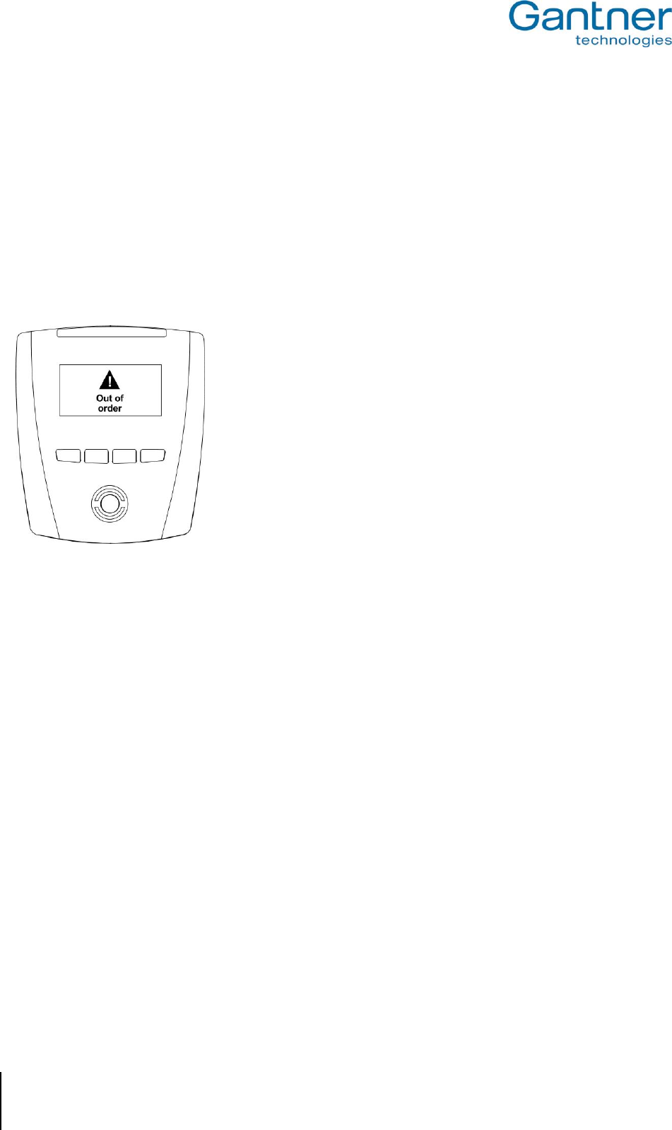
GAT Access 6100, GAT Access 6100 F BIO, GAT Access 6100 F Enrollment Station, GAT TimeAxx 6150
Operation
62
HB_GAT-ACCESS6100--EN_12
www.gantner.com
For the GAT Access 6100 F Enrollment Station, the configuration settings determine if the device displays the icons
that allow users to enrol and check fingerprints, or if these icons are not displayed.
Note: Emergency mode is not indicated via the display or the status LEDs.
5.8 Out of Order Screen
When communication of the GAT Access 6100 is interrupted and the GAT Access 6100 is not configured for
Emergency mode, the terminal switches into Out of Order mode. The following message is displayed on the LC
display.
Figure 5.11 - Out of order screen of GAT Access 6100
Note: The GAT Access 6100 will listen on the configured TCP/IP port (default 8000).
See chapter "6 Communication" for more information about how the GAT Access 6100 communicates with a server.
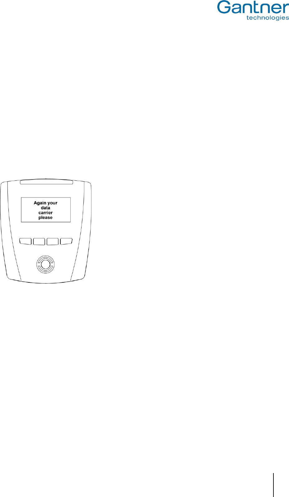
GAT Access 6100, GAT Access 6100 F BIO, GAT Access 6100 F Enrollment Station, GAT TimeAxx 6150
Operation
www.gantner.com
HB_GAT-ACCESS6100--EN_12
63
5.9 Locker Check-In
The GAT Access 6100 can be configured for locker check-in. When this function is active, the GAT Access 6100 will
automatically write or delete specific locker information on each data carrier.
Note: The same RFID data carriers, which are used for access control with the GAT Access 6100, can also be used
with GANTNER’s electronic locker systems.
The action to be performed by the GAT Access 6100 at locker check-in can be defined in the configuration settings
(see "4.3.3. List of Configuration Settings"). It is possible to delete the locker number from each data carrier that is
read or to write a specific validity date onto the data carrier.
When locker check-in is active, the user does not need to perform any additional action besides the normal
operation as described in "5.2. General ". Locker check-in is performed automatically. Ensure that the data carrier is
held in front of the reading field until the locker check-in process is complete. If the data carrier is removed before
the process is complete, access is denied and the GAT Access 6100 displays the following message.
Figure 5.12 - Information screen in Locker Check-In mode
In this case, the data carrier must be read again by the terminal. Access is granted only once the data carrier is
confirmed as valid and the check-in process is successfully completed.

GAT Access 6100, GAT Access 6100 F BIO, GAT Access 6100 F Enrollment Station, GAT TimeAxx 6150
Operation
64
HB_GAT-ACCESS6100--EN_12
www.gantner.com
5.10 General Open Function (Group Entry)
The GAT Access 6100 can be set to operate in "General Open" mode. When this function is active, the turnstile or
gate is permanently unlocked. The green LED and a corresponding message on the terminal's display indicate to
the user that the access point is open. In addition, the user does not have to present their data carrier for
identification at the terminal.
When the general open function is active, the connected management software receives a signal when someone
goes through the access point. This allows the software to manage the number of visitors entering the facility and
can be used to handle group entries for example.
The general open mode can be activated and deactivated with or without data carrier identification. This is a
configurable setting.
Note: To use the general open function, the GAT Access 6100 terminal requires firmware version 4.5.0 or higher
(see GANTNER partner web page).
5.11 External Release Function
The external release function allows external hardware, such as a push button or turnstile, to be activated (opened)
by the GAT Access 6100. The external hardware can connect to any of the terminal’s optocoupler inputs. The
function is activated in GAT Config Manager via the following this path: Configuration > Communication > Hardware
> Optocoupler > Function > External Release. The optocoupler’s “Event trigger” settings remain unchanged and can
be adjusted depending on the installation requirements.
Access through the door is automatically activated when the user presses the external push button (no card data is
sent). All configured relays are activated as in a normal access situation. For example, if Relay1 is configured to
"Entrance" in Config Manager and all other relays are configured to “No function”, then only Relay 1 will be activated
when an optocoupler set to “External Release” receives an input. Alternatively, if all the relays are configured to
“Entrance” then all relays are activated when any optocoupler set to “External Release” receives an input.
An additional setting for the external release function allows access information to be sent to the host software. This
setting is activated in Config Manager via: Configuration > Communication > Protocol > Enable Opto CardIdent.
Selecting this option box sends a “Card Ident” and “Action Started” command together with a UID of zero to the host
software when the optocoupler receives a signal. Host software could use this data to show information such as
how many people have gone through the door and at what time. The host software could also be configured to
restrict door access to certain times, e.g., the door relay is only activated after the external push button is pressed
during facility operating hours. Please note that these examples of host software configuration require additional
programming and it is the responsibility of the software developer to test all functional possibilities.
Note: To use the external release function, the GAT Access 6100 requires firmware version 4.5.0 or higher (see
the GANTNER partner web page).

GAT Access 6100, GAT Access 6100 F BIO, GAT Access 6100 F Enrollment Station, GAT TimeAxx 6150
Communication
www.gantner.com
HB_GAT-ACCESS6100--EN_12
65
6. COMMUNICATION
During operation and for configuration the GAT Access 6100 communicates with a server/host computer. For this
communication, the terminal uses certain protocols that are described in separate manuals. For regular use of the
GAT Access 6100 devices, it is not necessary to know the details of these protocols because the software package
GAT DIRECT.Connect from GANTNER Electronic GmbH offer a comfortable way for operation and configuration of
the GAT Access 6100 terminals. Please refer to the documentation of GAT DIRECT.Connect for implementation
details of the GANTNER devices.
Note: The GAT Access 6100 F Enrollment Station does also work offline without network connection. This chapter
describes the communication of the GAT Access 6100 and GAT Access 6100 F BIO terminals.
6.1 Online Mode
This is the standard operation mode of the GAT Access 6100. Online mode means that when a data carrier is read,
the GAT Access 6100 automatically sends the information of the data carrier over the interface to the server/host
and waits for an appropriate reaction from the server/host. The server evaluates the data and sends commands and
data to the GAT Access 6100 to control the function and set the data to be displayed.
Master and Slave:
In Online mode the GAT Access 6100 is in Master mode and the server/host computer is in Slave mode. The host is
queried cyclically by the GAT Access 6100 as to whether it wishes to transfer to the Master mode (for example in
order to carry out a configuration of the GAT Access 6100 or to upload events). If the host changes to Master mode
the GAT Access 6100 changes into the Slave mode. If during this mode no command has been received from the
host after a certain time, the GAT Access 6100 automatically changes back to the Master mode.
If the host does not respond to the queries of the GAT Access 6100 the access terminal changes, depending on
configuration, either into the Out Of Operation mode or into the Emergency mode.
6.2 Emergency Mode
Emergency Mode can be enabled or disabled in the functionality settings of a GAT Access 6100 (see "4.3.3. List of
Configuration Settings").
If Emergency Mode is enabled and if the communication to the server/host is lost, the GAT Access 6100 will switch
into Emergency mode. In this mode the terminal only checks the site key of a data carrier (company identification
number of FID) and if this is the same as the site key of the GAT Access 6100, access will be granted.
If the Locker Check-In function is activated, the GAT Access 6100 will also perform the locker Check-In by writing or
deleting certain data on the data carriers.
A GAT Access 6100 F Enrollment Station is usually operated in the Offline Emergency mode (see chapter “5.5.
User Operation at a GAT Access 6100 F Enrollment Station”).
As soon as communication is active again the GAT Access 6100 will switch back into normal Online mode.
6.3 Out of Operation Mode
If, after an identification at a GAT Access 6100, the host computer does not respond within a certain time after the
GAT Access 6100 read and sent the data carrier information, the access terminal will switch to the Out Of Operation
mode. In this mode, the GAT Access 6100 does not respond to any user action until the communication is restored.

GAT Access 6100, GAT Access 6100 F BIO, GAT Access 6100 F Enrollment Station, GAT TimeAxx 6150
Communication
66
HB_GAT-ACCESS6100--EN_12
www.gantner.com
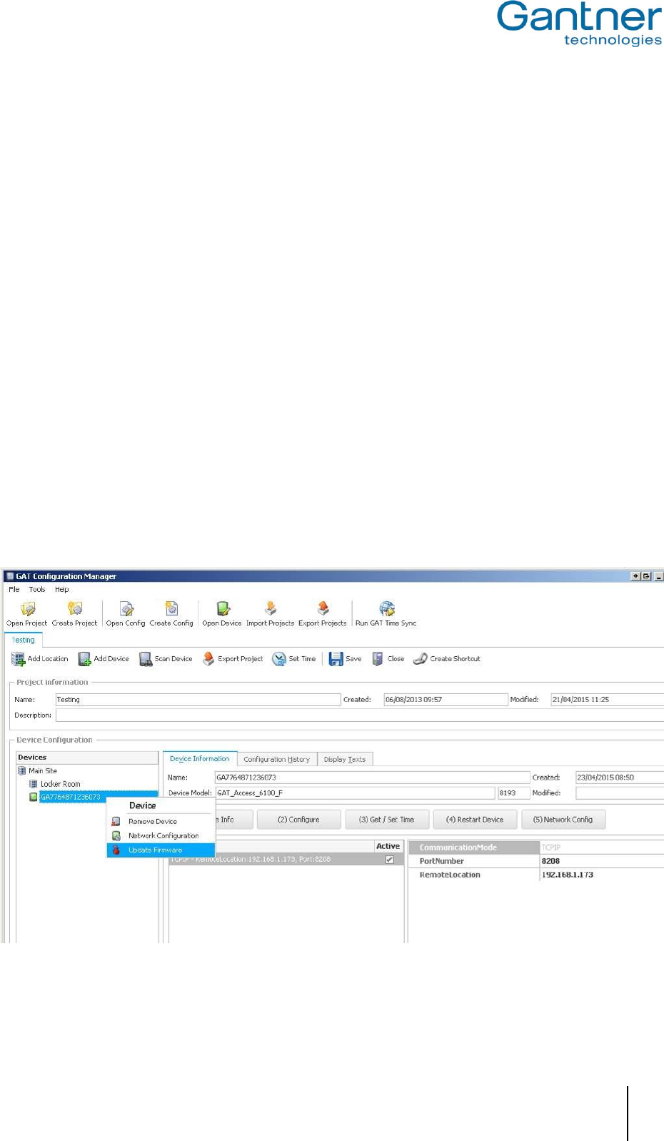
GAT Access 6100, GAT Access 6100 F BIO, GAT Access 6100 F Enrollment Station, GAT TimeAxx 6150
Updating the GAT Access 6xxx
www.gantner.com
HB_GAT-ACCESS6100--EN_12
67
7. UPDATING THE GAT ACCESS 6100
GANTNER Electronic GmbH periodically releases updates for the GAT Access 6100. New firmware versions can be
found and uploaded to the GAT Access 6100 using GAT Config Manager software.
Note: The firmware version currently installed in the GAT Access 6100 is displayed on the terminal information
screen upon start-up of the device (see Figure 4.2).
7.1 Updating with GAT Config Manager
The PC software GAT Config Manager is used to check for new firmware versions and to upload the update to the
GANTNER device. An internet connection is required to allow GAT Config Manager to connect to the GANTNER
server and check for possible updates.
Note: See the GAT Config Manager manual for detailed instructions on installing and operating GAT Config
Manager.
See section “4.3. Configuration Settings” for instructions on how to add a GAT Access 6100 to a project in GAT
Config Manager. Once the GAT Access 6100 is added to a project, complete the following steps to update the
device.
Right-click on the GAT Access 6100 in the device tree and select “Update Firmware” from the menu (Figure
7.1).
o The device update wizard opens.
Figure 7.1 – Update the GAT Access 6100 firmware
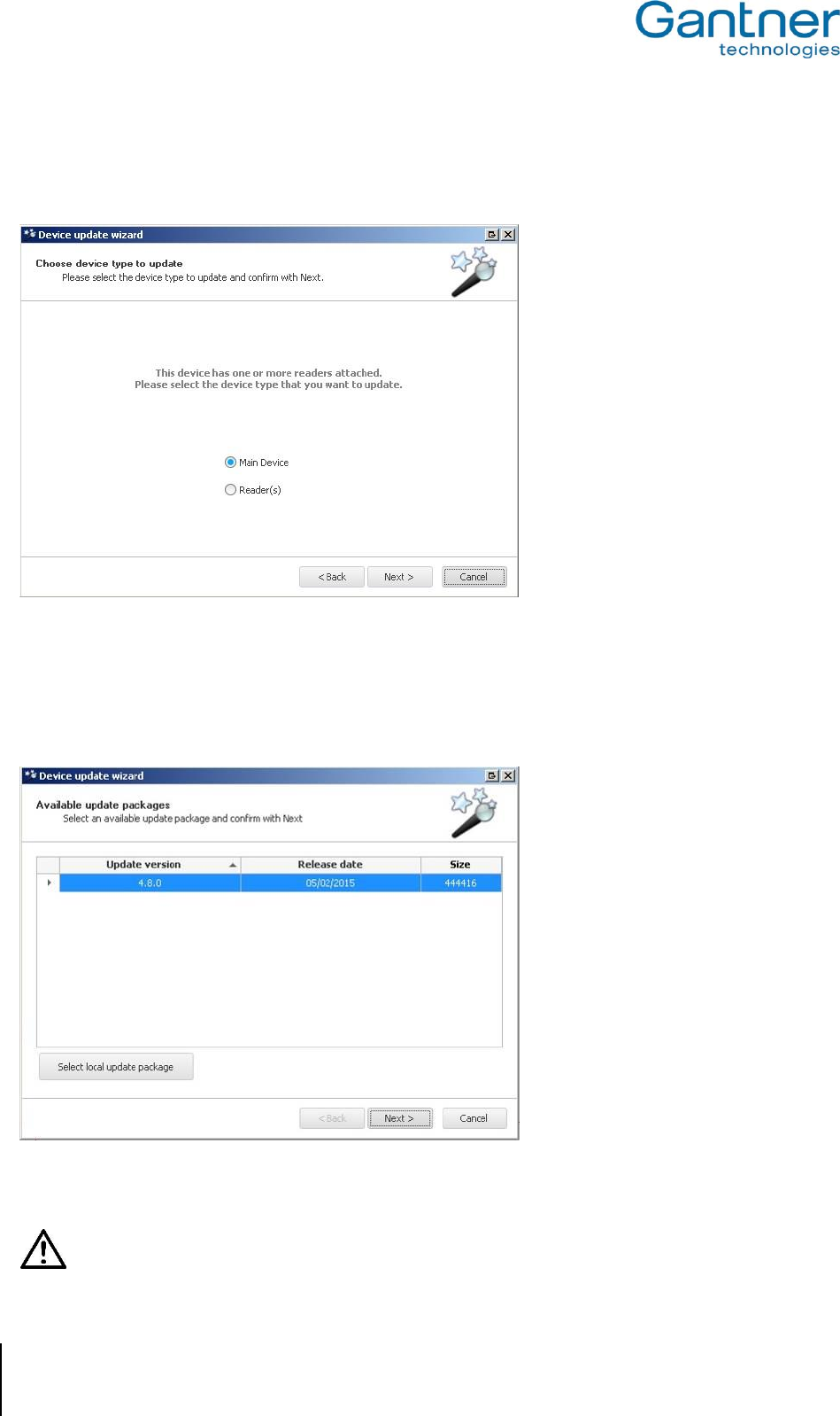
GAT Access 6100, GAT Access 6100 F BIO, GAT Access 6100 F Enrollment Station, GAT TimeAxx 6150
Updating the GAT Access 6xxx
68
HB_GAT-ACCESS6100--EN_12
www.gantner.com
Select “Main Device” in the first window then click “Next” (Figure 7.2).
o The wizard connects to the GANTNER server and returns a list of update packages.
Figure 7.2 – Device update wizard
If there is more than one update package available, select the newest version and click “Next”.
Note: A brief description of the changes included in the update is displayed when you mouse over the update
package.
Figure 7.3 – Select update version
Attention: Ensure there are no power or network interruptions during the update process.
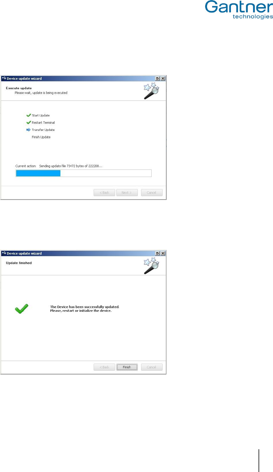
GAT Access 6100, GAT Access 6100 F BIO, GAT Access 6100 F Enrollment Station, GAT TimeAxx 6150
Updating the GAT Access 6xxx
www.gantner.com
HB_GAT-ACCESS6100--EN_12
69
The update wizard uploads the update to the GAT Access 6100. This process usually takes around 1 – 2
minutes depending on this size of the update, network speed, etc.
Figure 7.4 – Uploading file to GAT Access 6100
The update wizard displays the following message when the process is finished. Click on “Finish” to close the
wizard and return to the main page of GAT Config Manager.
Figure 7.5 – Update process successfully completed

GAT Access 6100, GAT Access 6100 F BIO, GAT Access 6100 F Enrollment Station, GAT TimeAxx 6150
Updating the GAT Access 6xxx
70
HB_GAT-ACCESS6100--EN_12
www.gantner.com

GAT Access 6100, GAT Access 6100 F BIO, GAT Access 6100 F Enrollment Station, GAT TimeAxx 6150
Troubleshooting and FAQ
www.gantner.com
HB_GAT-ACCESS6100--EN_12
71
8. TROUBLESHOOTING AND FAQ
This chapter contains "frequently asked questions" about the GAT Access 6100 and the corresponding solutions. In
case of questions about the GAT Access 6100 first read this chapter before contacting your installation partner or
GANTNER Electronic GmbH.
Note: A more detailed and continuously updated version of this FAQ list can be found on the GANTNER Electronic
GmbH Homepage "www.gantner.com" in the "Partner Login" section.
8.1 How can I update the firmware of a GAT Access 6100?
By using the software "GAT Config Manager" (see 7. Updating the GAT ACCESS 6100).
8.2 How do I configure a GAT Access 6100?
The GAT Access 6100 can be configured in different ways:
a) Directly at the device while the terminal is in Serivce mode (see "4.2 System Settings").
Note: Only system settings can be defined this way. The functionality settings are only defined like described in
the next step b).
b) Using the PC software "GAT Config Manager". This is done in three steps:
1. Starting the device configuration wizard.
2. Selecting the type of connection (TCP/IP) with the following parameters:
- Entering the IP address of the terminal
- Port number = 8208
3. Start the configuration by pressing the button "Start configuration".
- In case the DHCP status is changed from "OFF" to "ON", the GAT Access 6100 will perform a reset.
- If a relay has the function "External Locking", the relay "OnTime" is deactivated.
Note: The configuration with GAT Config Manager is described in chapter "4.3. Configuration Settings".
8.2.1 How do I activate service mode?
In service mode, the system settings (communication parameters, time and date, etc.) of a GAT Access 6100 can
be changed directly at the terminal. To enter service mode, perform the following steps:
a) Switch-off power and reconnect to power. The terminal will be reset and start-up.
b) Wait until the first line on the display shows "Settings".
c) Press the function keys of the GAT Access 6100 in the following sequence: 1 - 1 - 4 - 4 - 2 - 3. The service
menu will be shown on the display.
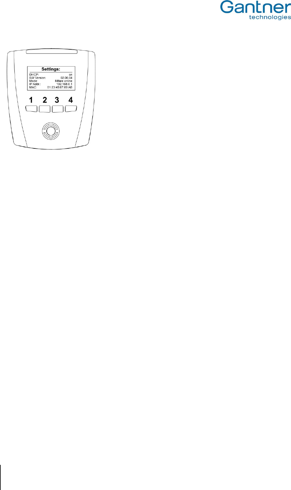
GAT Access 6100, GAT Access 6100 F BIO, GAT Access 6100 F Enrollment Station, GAT TimeAxx 6150
Troubleshooting and FAQ
72
HB_GAT-ACCESS6100--EN_12
www.gantner.com
Note: See "4.2 System Settings" for more information about the Service mode or Service menu respectively.
8.3 Which TCP/IP ports can be used by a GAT Access 6100?
- Port 8000: For communication
- Port 8208: For configuration (GAT Config Manager)
8.4 Which bit rates are used by a GAT Access 6100 for Ethernet and is this configurable?
The GAT Access 6100 operates with bit rates of 10 and 100 Mbit/s. The terminal decides automatically which bit
rate to use or it is also possible to configure the bit rate fix to 10 Mbit/s.
8.5 How can I set the date and time of a GAT Access 6100?
If the date and time of a GAT Access 6100 are no longer correct, it is possible to adjust date and time in different ways:
a) With GAT Config Manager software (see "4.3. Configuration Settings").
b) Directly at the terminal in the Service mode (see 4.2. System Settings")
c) With the FUNLINE protocol command "Set_Date" and "Set_Address".
d) With the software GAT TimeSync, which is part of the GAT SyncManager software.
8.6 How can I find the IP address of a GAT Access 6100 and change it?
There are different possibilities:
a) Read and set the address directly at the GAT Access 6100. The GANTNER technology logo is shown when the
GAT Access 6100 powers on. After a brief pause, the "Settings" screen with information including the IP
address, DHCP ON/OFF, software version, terminal address and reader technology is shown (see "4.2. System
Settings"). The IP address can be changed in the Service menu (see "4.2.1. Service Menu of GAT Access
6100").
b) With the GAT Device Finder software.
c) With GAT Config Manager software.
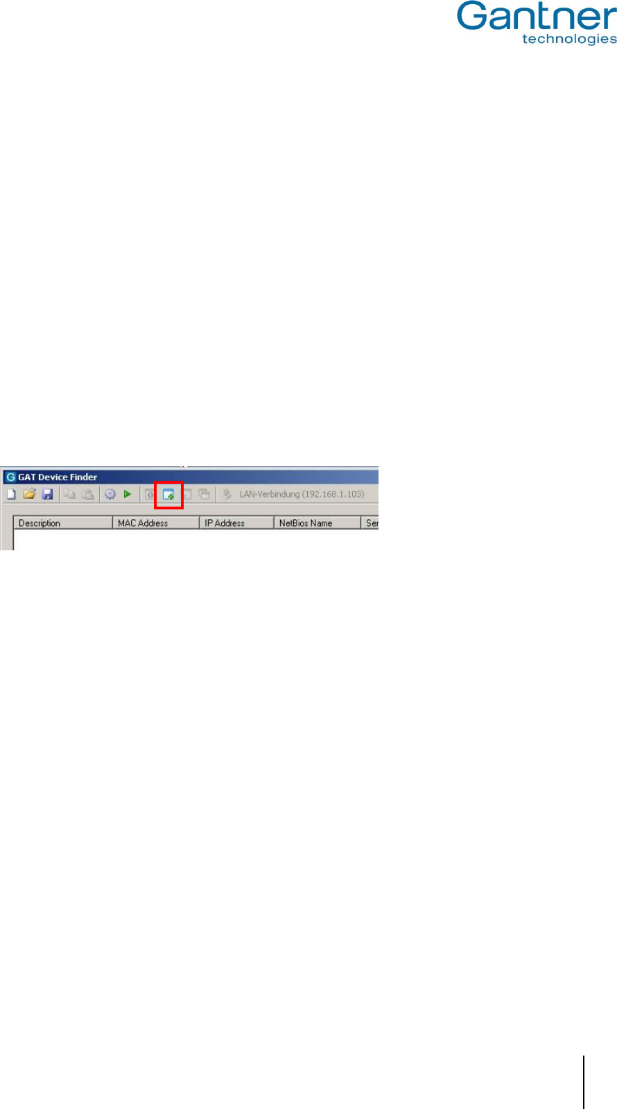
GAT Access 6100, GAT Access 6100 F BIO, GAT Access 6100 F Enrollment Station, GAT TimeAxx 6150
Troubleshooting and FAQ
www.gantner.com
HB_GAT-ACCESS6100--EN_12
73
8.7 How can I find the MAC address of a GAT Access 6100?
There are different possibilities:
a) Directly at the device. The GANTNER technology logo is shown when the GAT Access 6100 powers on. After a
brief pause, the "Settings" screen with information including the MAC address, IP address, DHCP ON/OFF,
software version, terminal address and reader technology is shown (see "4.2. System Settings").
b) The MAC address can also be shown in the Service menu (see "4.2.1. Service Menu of GAT Access 6100") by
selecting "Communication" -> "MAC Address".
c) Label on the processor of the GAT Access 6100.
d) With the GAT Device Finder software.
8.8 Setting IP address when MAC address is not known and IP address of the terminal is
0.0.0.0
There are different possibilities:
a) If DHCP is activated, install a DCHP server.
b) Restart the GAT Device Finder software and the GAT Access 6100. If DHCP is activated it is possible to select
the MAC address of the GAT Access 6100 with the icon "Add new Device" and then set the desired IP address.
8.9 Difference between "Time" and "Delay" in the "Mode" field for Locker Check-In
configuration?
With "Time", the hours and minutes will be written onto the data carriers exactly as they are entered in the "Hours"
and "Minutes" fields.
With "Delay", the terminal will add the values entered in the "Hours" and "Minutes" fields to the current time of the
terminal and write the resulting value onto the data carriers.
Example:
Current date and time of the terminal: November 24th 2010 12:31:00
Field "Hours": 02
Field "Minutes": 15
If mode is set to "Time", the terminal will write "24.11.2010 02:15:00" onto the data carrier.
If mode is set to "Delay", the terminal will write "24.11.2010 14:46:00" onto the data carrier.

GAT Access 6100, GAT Access 6100 F BIO, GAT Access 6100 F Enrollment Station, GAT TimeAxx 6150
Troubleshooting and FAQ
74
HB_GAT-ACCESS6100--EN_12
www.gantner.com
8.10 Meaning of optocoupler settings "Rising_Edge", "Falling_Edge", "Rising- and Falling
Edge"?
Optocouplers are digital inputs used for status acquisition, for example if a turnstile or door, connected to the GAT
Access 6100, is closed or opened.
When set to "Rising_Edge" the terminal will send the "Action_Started" command in case the optocoupler is active
(i.e. current). When set to "Falling_Edge" the terminal will send the "Action_Started" command in case the
optocoupler is NOT active (i.e. no current). When set to "Rising- and Falling Edge" the terminal will send the
"Action_Started" command when the optocoupler is activated OR deactivated, depending which happens first.
8.11 How can the reader of a GAT Access 6100 B be authorised for LEGIC®?
To authorise for LEGIC® means that the GAT Access 6100 B reader is registered to be able to read and write
segments of LEGIC® data carriers (e.g. locker segments). Authorising for LEGIC® is only possible with a GAT
Access 6100 B terminal, because only this terminal has a built-in LEGIC® reader.
The device can be registered in different ways:
a) During normal operation (while the terminal is in normal Online mode) hold the authorisation card (SM100 or
SAM-63 resp.) next to the scan field for approx. 30 seconds.
b) In the Service menu (see "4.2. System Settings") select "Reader" -> "Read UID" and then hold the authorisation
card (SM100 or SAM-63 resp.) to the scan field for approx. 30 seconds until the UID number is shown on the
display.
c) With the "Enable_Authorisation" command of the FUNLINE protocol (see protocol manual) and an authorisation
card (SM100 or SAM-63 resp.).
Note: The value of the site key in the configuration must be the same as the one of the authorisation card. In case
of problems also check the sub-site key and the groups.
8.12 How can I read or delete the authorisation data of a GAT Access 6100?
The authorisation data of a LEGIC® GAT Access 6100 B reader can be read or deleted in different ways:
b) In the Service menu (see "4.2. System Settings") select "Reader" and in the next menu either "Read Authoris."
or "Delete Authoris." to show or delete the authorisation data on the display. Note that if the authorisation is
deleted, no further writing of LEGIC® data carriers is possible (e.g. for Locker Check-In).
c) With the "Read_Authorisation_Data" or "Clear_Authorisation_Data" command of the FUNLINE protocol (see
protocol manual).
8.13 How can I configure the display texts of a GAT Access 6100?
The display texts of a GAT Access 6100 are set by default, but can be changed with the GAT Config Manager
software (see "4.3.4. Display Texts").

GAT Access 6100, GAT Access 6100 F BIO, GAT Access 6100 F Enrollment Station, GAT TimeAxx 6150
Troubleshooting and FAQ
www.gantner.com
HB_GAT-ACCESS6100--EN_12
75
8.14 The relay of the GAT Access 6100 is activated even if the host has denied access.
The relay is configured as "External_Locking" and is activated, as soon as the access terminal has read the unique
number UID of a data carrier.
Solution:
Set the relay to "No_Function" or "Turnstile" function.
8.15 Which FUNLINE protocol commands are supported by a GAT Access 6100?
Offline Commands:
- Set_Address - Repeat_Event - Set_Addr_Extended
- Set_Date - Delete_Events - Set_Protocol_Type
- Ident_Read_Date - Pass_Master - Enable_Baptism
- Test_Connection - TriggerMasterMode - Read_Baptism
- Read_Event - Reset - Clear_Baptism
Online Commands:
- Pass_Master - Card_Ident - Action_Started
8.16 Why does the GAT Access 6100 deny access with my data carrier in Emergency mode?
In emergency mode a GAT Access 6100 reads a certain segment (LEGIC®: configurable, MIFARE®: locker
segment, ISO 15693: general segment) of the data carriers. If the site-key is correct (same site-key on data carrier
and in the terminal) access is granted, otherwise the data carrier is rejected and access is denied.
8.17 What is the maximum start-up current consumption of a GAT Access 6100?
VIn Imax
12 V 7 A
16 V 10 A
20 V 12 A
24 V 15 A
See also chapter “9. Technical Data”.
8.18 What are the factory settings of a GAT Access 6100?
Ethernet:
- TCP Communication Port: 8000
- DHCP enabled: true
- Static IP Address: 192.168.1.37
- Static Subnet Mask: 255.255.255.0
- Static Primary DNS Server: 192.168.1.13
- Static Secondary DNS Server: 192.168.1.11
- Static Default Gateway: 192.168.1.6
- NetBIOS name: GA<PartNo.><SerialNo.>
- 100 Mbit Ethernet enabled: true

GAT Access 6100, GAT Access 6100 F BIO, GAT Access 6100 F Enrollment Station, GAT TimeAxx 6150
Troubleshooting and FAQ
76
HB_GAT-ACCESS6100--EN_12
www.gantner.com
Hardware:
- Terminal Address: 255
- Type: Leisure
- Communication Mode: Online
- Leisure Omron Mode Active: false
- Button Event Enabled: false
- Verify Before CardIdent: false
Relay 1:
- Default state: NO
- Pulse Time: 300
- Function: Entrance
Optocoupler 1:
- Function: Entrance
- Event Trigger: Falling Edge
Fingerprint:
- Verification Level: 5
- Mode Verification: Deactivated
- Number Fingers: 2
- Site key: 0
Display:
- Contrast: 10
General:
- Time Format: 0-24
- Emergency Mode Enabled: false
- Device Licence: 0
Data Handling:
- Deny if Checkin Failed: false
- Check Validity Date: false
Locker 1:
- Read: false
- Position on Card: 4
- Clear number: false
Start Date:
- Mode: None
- Hours: 0
- Minutes: 0
End Date:
- Mode: None
- Hours: 0
- Minutes: 0

GAT Access 6100, GAT Access 6100 F BIO, GAT Access 6100 F Enrollment Station, GAT TimeAxx 6150
Troubleshooting and FAQ
www.gantner.com
HB_GAT-ACCESS6100--EN_12
77
Locker 2:
- Read: false
- Position on Card: 5
- Clear number: false
Start Date:
- Mode: None
- Hours: 0
- Minutes: 0
End Date:
- Mode: None
- Hours: 0
- Minutes: 0
Fingerprint:
- Position on Card Base: 6
Timeouts:
- Access allowed screen: 3000
- Access denied screen: 3000
MIFARE:
- Site Key: 73E0…
- Subsite: 00
- Enable Subsite: false
8.19 How do I configure a GAT Access 6100 for offline emergency mode?
For the GAT Access 6100, there is the possibility to load an Offline Licence into the terminal. With this licence, the
terminal checks if a specific code string is stored in a defined position on the data carrier and if the data carrier has
access permission.
The Offline Licence can be ordered from GANTNER Electronic GmbH. The serial number and MAC address of the
GAT Access 6100 is required and the licence is valid only for one terminal.
To load the licence into the GAT Access 6100, GAT Config Manager software from GANTNER Electronic GmbH is
used (see chapter "4.4. Configuration of Offline Emergency Mode for a GAT Access 6100 ").
8.20 What is the data carrier certificate?
The GAT Access 6100 checks the data carrier certificate to confirm that it is a GANTNER data carrier. In basic
configuration only GANTNER data carriers are allowed.
It is possible to order a device licence that deactivates the certificate test thereby allowing third party data carriers to
be used.

GAT Access 6100, GAT Access 6100 F BIO, GAT Access 6100 F Enrollment Station, GAT TimeAxx 6150
Troubleshooting and FAQ
78
HB_GAT-ACCESS6100--EN_12
www.gantner.com

GAT Access 6100, GAT Access 6100 F BIO, GAT Access 6100 F Enrollment Station, GAT TimeAxx 6150
Technical Data
www.gantner.com
HB_GAT-ACCESS6100--EN_12
79
9. TECHNICAL DATA
Nominal voltage: 12/24 VDC (SELV - safety extra-low voltage)
Permitted input voltage: 10 to 28 VDC
Aver. power consumption
- GAT Access 6100: 3 W
- GAT Access 6100 F BIO: - Full operation with sensor on: 4.5 W
- Full operation with sensor off: 3.5 W
- GAT Access 6100 F Enrollment Stat.: - Full operation with sensor on: 4.5 W
- Full operation with sensor off: 3.5 W
Data storage: Internal flash memory for configuring and booking memory, data
preservation min. 10 years
Internal clock Crystal-controlled real-time clock, data preservation approx. 12 h (gold-cap)
Reader types
- GAT Access 6100 B: LEGIC® Prime
- GAT Access 6100 ISO: ISO 15693
- GAT Access 6100 F: MIFARE®
- GAT Access 6100 F BIO: MIFARE®
- GAT Access 6100 F Enrollment Stat.: MIFARE®
Reader frequency: 13.56 MHz
Control elements: - RFID reader
- 4 function keys
Display elements: - Full graphics monochrome display with white LED background lighting,
resolution 128 x 64 pixels, visible area 50 x 25 mm
- RFID reader (illuminated)
- 4-segment LED display in different colours (green / red / yellow)
- Acoustic signal
Finger print scanner type: Optical sensor, 500 dpi @ 8 bit per pixel, active areas: 13 x 20 mm
Verification time of finger prints: < 0.8 seconds
Identification time: < 1 second
Accepted wrong detection rate: 0.01% (recommended), adjustable
Host interface: Ethernet 10/100 Mbit/s
Signal input: 1 x optocoupler (configurable)
- Input voltage: 0 to 30 VDC, ULow < 2 VDC, UHigh > 6 VDC
- Input current: 4.5 mA
Signal output: 1 x relay (configurable NO/NC)
- Switching voltage: max. 30 VAC/DC
- Continuous current: max. 2 A
- Switching power: max. 60 VA
Connection terminals: 0.5 to 1.5 mm2
Housing material: - Upper part: Shockproof plastic PMMA
- Lower part: Shockproof plastic PC-ABS
- Stand of Enrollment Station: aluminium
Dimensions: see drawings below

GAT Access 6100, GAT Access 6100 F BIO, GAT Access 6100 F Enrollment Station, GAT TimeAxx 6150
Technical Data
80
HB_GAT-ACCESS6100--EN_12
www.gantner.com
Permitted ambient temperature: -10 to +55 °C
Storage temperature: -20 to +70 °C
Relative humidity: 20 to 80%, non-condensing
Protection type: IP 54
Protection class: III
Weight:
- GAT Access 6100 B, F, ISO, F BIO: Approx. 0.2 kg
- GAT Access 6100 F Enrollment Stat.: Approx 1 kg
Environment class based on VDS 2110: II (conditions in indoor areas)
Certification of finger scanner: CE and FCC15
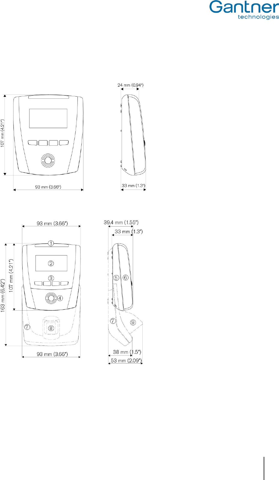
GAT Access 6100, GAT Access 6100 F BIO, GAT Access 6100 F Enrollment Station, GAT TimeAxx 6150
Technical Data
www.gantner.com
HB_GAT-ACCESS6100--EN_12
81
9.1 Dimensions
9.1.1 GAT Access 6100
9.1.2 GAT Access 6100 F BIO
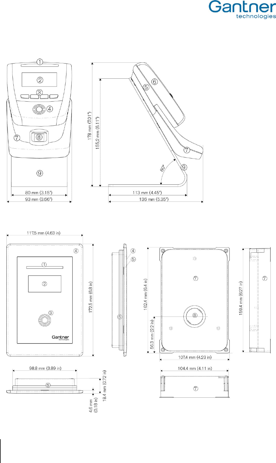
GAT Access 6100, GAT Access 6100 F BIO, GAT Access 6100 F Enrollment Station, GAT TimeAxx 6150
Technical Data
82
HB_GAT-ACCESS6100--EN_12
www.gantner.com
9.1.3 GAT Access 6100 F Enrollment Station
9.1.4 GAT TimeAxx 6150

GAT Access 6100, GAT Access 6100 F BIO, GAT Access 6100 F Enrollment Station, GAT TimeAxx 6150
Technical Data
www.gantner.com
HB_GAT-ACCESS6100--EN_12
83
9.1.5 FCC and ICES Information
Applicable for the following devices:
- GAT Access 6100 F
- GAT Access 6100 F BIO
- GAT Access 6100 F Enrollment Station
FCC INFORMATION (U.S.A.)
Note: This equipment has been tested and found to comply with the limits for a Class B digital device, pursuant to
part 15 of the FCC Rules. These limits are designed to provide reasonable protection against harmful
interference in a residential installation. This equipment generates, uses, and can radiate radio frequency
energy and, if not installed and used in accordance with the instructions, may cause harmful interference to
radio communications. However, there is no guarantee that interference will not occur in a particular
installation. If this equipment does cause harmful interference to radio or television reception, which can be
determined by turning the equipment off and on, the user is encouraged to try to correct the interference by
one or more of the following measures:
- Reorient or relocate the receiving antenna.
- Increase the separation between the equipment and receiver.
- Connect the equipment into an outlet on a circuit different from that of which the receiver is connected.
- Consult the dealer or an experienced radio/TV technician for help.
FCC Warning Statement
[Any] changes or modifications not expressly approved by the party responsible for compliance could void the user's
authority to operate the equipment.
ICES Statement (Canada)
This Class B digital apparatus complies with Canadian ICES-003.
Cet appareil numérique de la classe B est conforme à la norme NMB-003 du Canada.

GAT Access 6100, GAT Access 6100 F BIO, GAT Access 6100 F Enrollment Station, GAT TimeAxx 6150
Technical Data
84
HB_GAT-ACCESS6100--EN_12
www.gantner.com
_ _
Note:
This manual is valid as of August 27th, 2015. It is subject to change.
Amendments and changes can be made without prior notice at any time.

86
HB_GAT-ACCESS6100--EN_12
www.gantner.com
Part No.: 332727 www.gantner.com
GANTNER Electronic GmbH GANTNER Electronic GmbH Deutschland GANTNER Electronics Pty Ltd Australia
Montafonerstraße 8 Industriestraße 40F 3/105a Vanessa St, Kingsgrove
6780 Schruns, Austria 44894 Bochum, Germany NSW 2208, Australia
T: +43 5556 73784-0 T: +49 234 58896-0 T: +61 2 9011 8114
F: +43 5556 73784-8000 F: +49 234 58896-11 F: +61 2 8209 1708
info@gantner.com info-de@gantner.com info-aus@gantner.com
GANTNER Electronics Ltd. UK GANTNER Electronic GmbH Middle East
16 The Havens, Ransomes Europark P.O. Box 62702, Office 1604, Aspect Tower
Ipswich, Suffolk, IP3 9SJ Business Bay, Sheikh Zayed Road, Dubai, UAE
United Kingdom T: +971 4 451 7794
T: +44 1245 697 588 F: +971 4 451 7795
Tech. Line: +44 1480 212 627 M: +971 50 650 4082
info-uk@gantner.com info-me@gantner.com