Gantner Electronic GEA1150002A Access Control Terminal, Access Control Terminal with Biometry User Manual Brochure 6100
Gantner Electronic GmbH Access Control Terminal, Access Control Terminal with Biometry Brochure 6100
Contents
- 1. User Manual
- 2. Brochure 6100
- 3. Brochure 6100F
Brochure 6100

Function description
The GAT Access 6100 reads contact-free data carriers and checks and
grants authorisations. The user holds the data carrier over the round
scan field and selects the required service via the acknowledge key. The
integrated 4-segment LED display, monochrome LCD display and acoustic
signal indicate authorisation.
Further functions:
• Activation of turnstiles, doors etc. via relay output
• Feedback input
• User guidance via monochrome display (LCD), 4-segment LED display,
illuminated round scan field and beeper
• Secure data transmission between reader and data carrier
• RFID frequency 13.56 MHz
• Reading of LEGIC®, MIFARETM standard and ISO 15693 data carriers
(depending on the device type)
• Opening of housing only possible with special tool
• Plug & Play installation
GAT Access 6100
Access Control Terminal
Application
The GAT Access 6100 is a stylish terminal for access control in leisure
facilities such as swimming pools, spas and gyms. Identification at
the terminal is by contact-free RFID data carrier (Radio Frequency
Identification).
Information display for user guidance is realised via a graphical mono-
chrome display (LCD). The different versions (see order information) give
technological flexibility.
Description PartNo.
GAT Access 6100 B
Access control terminal with monochrome display (LCD)
and contact-free reader for LEGIC® data carriers
651681
GAT Access 6100 F
Access control terminal with monochrome display (LCD)
and contact-free reader for MIFARETM data carriers
776487
GAT Access 6100 ISO
Access control terminal with monochrome display (LCD)
and contact-free reader for ISO 15693 data carriers
651782
1
www.gantner.com
Order information
Description PartNo.
GAT Access 6100 Manual
Operating and configuration instructions, English
332727
GAT Reader WK
Tool to open the reader housing
581683
Accessories
Valid as from July 30
th
, 2013 • Technical data subject to modifications without notice!
DB_GAT-ACCESS6100--EN_11.indd • PartNo.: 860279
Nominal voltage: 12/24 VDC (SELV - safety extra-low
voltage)
Permitted input voltage: 10 to 28 VDC
Aver. power consumption: 3 W
Data storage: Internal EEPROM memory for
configuring and booking memory,
data preservation min. 10 years
Internal clock: Data preservation approx. 12 h
(Gold-Cap)
Reader type: See order information
Frequency of reading field: 13.56 MHz
Control elements: - 4 function keys
- RFID reader
Display elements: - Full graphics monochrome display
(LCD) with white LED background
lighting, resolution 128 x 64 pixels,
visible area 50 x 25 mm
- RFID reader (illuminated)
- Acoustic signal
- 4-segment LED display with
different colours
Host interface: Ethernet 10/100 MBit/s
Signal input: 1 x optocoupler (configurable)
- Input voltage: 0 to 30 VDC
ULow < 2 VDC, UHigh > 6 VDC
- Input current: 4.5 mA
Signal output: 1 x relay (configurable NO/NC)
- Switching voltage: max. 30 VAC/DC
- Continuous current: max. 2 A
- Switching power: max. 60 VA
Connection terminals: 0.5 to 1.5 mm2
Housing material: - Upper part: plastic PMMA
- Back part: plastic PC-ABS
Dimensions: 93 x 107 x 33 mm
Permitted ambient temperature: -10 to +55°C
Storage temperature: -20 to +70°C
Relative humidity: 20 to 80%, non-condensing
Protection type: IP 54
Protection class: III
Weight: 0.2 kg
Environment class
based on VDS 2110: II (conditions in indoor areas)
2www.gantner.com
Technical data
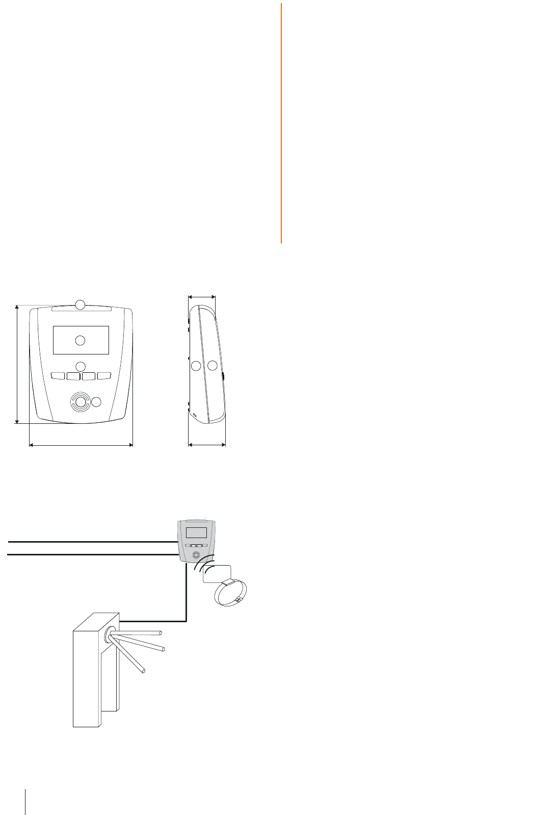
93 mm (3.66”) 33 mm (1.3”)
24 mm (0.94”)
107 mm (4.2”)
2
3
4
56
1
Typical application
Turnstile
RFID data carriers
GAT Access 6100
Power supply
Network
Dimensions
1. 4-segment LED display
2. Monochrome display (LCD)
3. Function keys
4. Illuminated, round scan field
5. Device back part
6. Device upper part
Valid as from July 30
th
, 2013 • Technical data subject to modifications without notice!
DB_GAT-ACCESS6100--EN_11.indd • PartNo.: 860279
3
www.gantner.com
Valid as from July 30
th
, 2013 • Technical data subject to modifications without notice!
DB_GAT-ACCESS6100--EN_11.indd • PartNo.: 860279
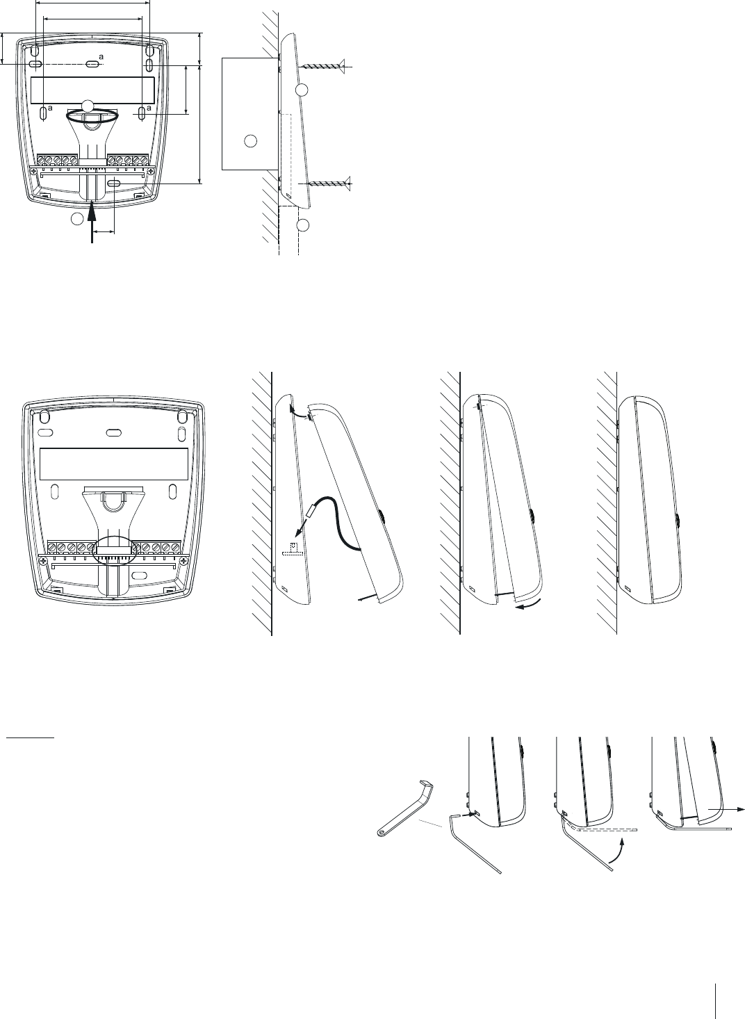
Mounting and installation instructions
The device back part is secured by screws to a flat background (e.g.
concrete wall). When fixing to an uneven background the device back part
must not be distorted as this will prevent correct connection of the upper
part. Recommended mounting height: top edge of device 1.3 m.
Use the drilling template which is attached to the device.
Mounting the device upper part
Once the connection cables are terminated, the device back part and upper
part are connected together via a connection cable (already connected in
the upper part) and the two parts are fixed together.
1. 2.
Notes:
1. Check the socket in the device back part (circled in figure 1). Dirt,
dust and humidity must be removed so that a good contact of the
connection cable is guaranteed. No aggressive detergent may be
used. Please do not damage socket contacts.
Attention: Cleaning only in powerless state.
2. Plug in the connection cable into the socket in the device back part
(consider alignment) and clip the top of the device upper part into the
device back part.
Wall mounting
Cables can be flush (1) or suface-mounted (2).
When surface mounting please check whether the cables can still be
inserted once the device back part has been mounted, otherwise run the
cables through the cable lead-ins prior to securing.
1. Flush-mounted cable
2. Surface-mounted cable
3. Back box
4. Device back part
5. Cable conduit for surface cable connection
3. 4.
3. Swing down the device upper part until it clicks.
4. The device can only be opened with the supplied special tool! With
this the two catches on the bottom of the device can be unlocked in
succession.
69 mm (2.72”)
13 mm (0.51”)
18.5 mm (0.73”)
28.5 mm (1.12”) 20 mm
(0.79”)
71 mm (2.8”)
60 mm (2.36”)
2
3
4
5
1
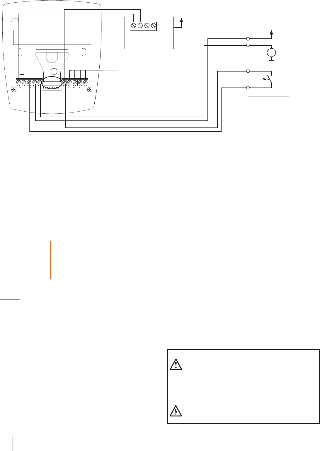
Electrical connections
TCP/IP with external power supply
4www.gantner.com
Valid as from July 30
th
, 2013 • Technical data subject to modifications without notice!
DB_GAT-ACCESS6100--EN_11.indd • PartNo.: 860279
Network
Ethernet, Connection via screw terminals.
Power supply
DC supply (see technical data), e.g. via GANTNER GAT Power Supply
SP014/1. The power input is protected against reverse-polarity.
Recommended cables:
Ethernet: min. CAT 5 (STP) for 100 MBit
Wire colours
Ethernet 10/100 MBit
Connection to the device upper part
Attention: The socket (3) for the connection cable between the device
back part and the device upper part must be clean in order to guarantee
a good contact.
568A 568B
TX + green/white orange/white
TX - green orange
RX + orange/white green/white
RX - orange green
Relay output
For activation of devices like turnstiles etc.. The relay contact is of type
NO (maker contact). Please observe the max. permitted switching voltages
and currents (see technical data).
Depending on the connected instalation (e.g. turnstile) an additional free-
wheeling diode may be necessary, which is used to limit the switch-on
current. Please read the documentation of the connected installation.
Optocoupler input
Input for status acquisition. For using the input a supply voltage must be
applied. This voltage can be taken from the terminal‘s supply or from an
external power source. Please observe the max. permitted input voltages
and currents (see technical data).
GAT Access 6100
RX +
TX -
TX +
GND
NO 1
C 1
IN1 -
IN1 +
RX -
VIN +
TCP/IP
Power supply unit
e.g. GAT Power Supply SP014/1
VOut+
GND
A
B
Mains power
Motor control
Feedback control
M
e.g. Turnstile
1
Safety instructions
- This device must be installed by qualified personnel only.
- The applicable safety and accident prevention regulations
must be observed.
- Safety devices must not be removed.
- Please observe the technical data of the device specified
on the data sheet.
- The device must be disconnected from the power supply
prior to installation, assembly or dismantling.