Contents
- 1. Users Manual part 1of4
- 2. Users Manual part 2of4
- 3. Users Manual part 3of4
- 4. Users Manual part 4of4
Users Manual part 4of4
%DLO0RXQWLQJ
,QVWUXFWLRQV
:$51,1*
See the Important Safety and Product
Information guide in the GPS device
product box for product warnings and
other important information.
Garmin® strongly recommends having an
experienced installer with the proper
knowledge of electrical systems install the
device. Incorrectly wiring the power cable
can result in damage to the vehicle or the
battery and can cause bodily injury.
&$87,21
Always wear safety goggles, ear
protection, and a dust mask when drilling,
cutting, or sanding.
NOTICE
The metal contacts on the GPS device
and the mount should be kept dry to avoid
equipment damage. Use the weather cap
on the mount at all times when the unit is
not mounted to keep the metal contacts
dry and protected.
To obtain the best performance and to
avoid damage to your boat, install the
device according to these instructions.
Read all installation instructions before
proceeding with the installation. If you
experience difficulty during the installation,
contact Garmin Product Support.
7RROV1HHGHG
• Drill
• Phillips screwdriver
• 9.5 mm (3/8 in.) wrench or socket
• 3 bolts or 3 screws:
◦#8 (4 mm) pan-head machine bolts
with nuts and washers, and a
5 mm (5/32 in.) drill bit
◦#8 (4 mm) pan-head self-tapping
screws and a 1.5 mm (1/16 in.) drill
bit
0RXQWLQJ&RQVLGHUDWLRQV
NOTICE
The swivel base must be mounted using
pan-head machine bolts or self-tapping
screws. Using screws with countersunk
heads can damage the mounting bracket.
DRAFT
A
ng an an
oper
ms install thems install the
he power cablehe power cable
the vehicle or thethe vehicle or the
se bodily injury.dily injury.
DR
DR
D
D
&$87,21
safety goggles, ear
safety goggles, e
a dust mask whea dust mask wh
D
D
CE
allall
ng with thng wi
ience difficulty d
ience diff
ntact Garmin Product
ntact Garmin Pr
7RROV1HHGHG7RROV1HHGHG
••
DrillDrill
•
Phillips scPhil
• 9.5 mm• 9.5 m
•3 b3b
The device should be mounted in a
location that provides a clear view of the
screen and is easy to reach.
The device should be mounted in a
location that is sturdy enough to support
the mount and device.
The device must be mounted in a location
that allows room to route and connect the
cables. You should allow at least 8 cm
(3 in.) of clearance behind the case.
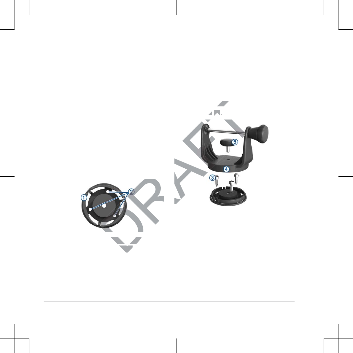
0RXQWLQJWKH%UDFNHW
$VVHPEO\
Separate the swivel base ➀ from the
mount.
Using the swivel base as a template,
mark the pilot hole locations ➁.
Select an option:
• If you intend to secure the base
with machine bolts, drill three 5 mm
(5/32 in.) holes.
• If you intend to secure the base
with self-tapping screws, drill three
1.5 mm (1/16 in.) starter holes.
127(Do not make the holes
deeper than half of the screw
length.
Secure the swivel base with the bolts
or screws ➂.
Place the swivel mount bracket ➃
over the swivel base and secure it with
the short knob ➄.
,QVWDOOLQJWKH0RXQWRQWKH
0RXQWLQJ%UDFNHW
Align the slot ➀ on the back of the
cradle with the long mounting knob ➁,
2 Important Safety Information
DRA
e
se as a tempse as a tem
ations ations
T
swivel bswiv
ws ws
➂➂
..
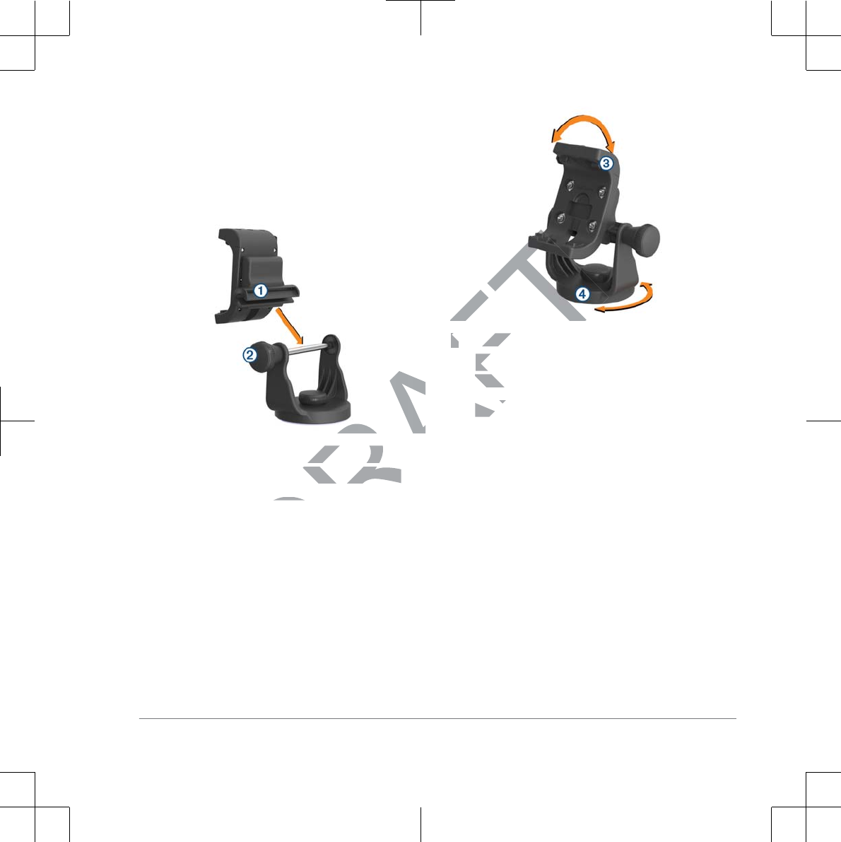
and slide the cradle into place on the
bar.
127(You can turn the long mounting
knob to adjust the width of the bracket
arms.
Adjust the angle of the cradle, and
tighten the long mounting knob until
the cradle ➂ is secure.
Rotate the swivel mount bracket ➃ to
an optimal viewing angle, and tighten
the knob.
The bracket clicks as you turn it.
&RQQHFWLQJ3RZHUWRWKH
0RXQW
Select a mounting location based on
available power sources, safe cable
routing, and an unobstructed view.
Connect the cables.
Important Safety Information 3
DRAFT
e cradle, ande cradle, an
ounting knob untilnting knob until
secure.secur
Rotate the swivRotat
an optimal van
the knobthe k
The bThe b
&RQ
0
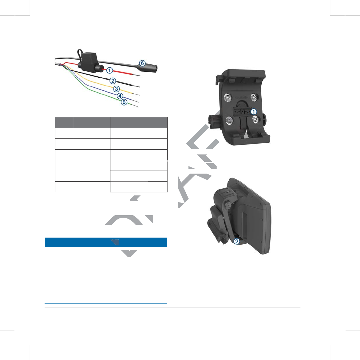
,WHP :LUH&RORU :LUH)XQFWLRQ
➀Red Power
➁Black Power
➂Yellow Serial data input
➃Blue Serial data output
➄Green Serial ground wire
➅Audio jack
Insulate and secure unconnected
wires.
,QVWDOOLQJWKH'HYLFHLQWKH
0RXQW
NOTICE
Before you place the device in the mount,
ensure that the metal contacts on the
device and the mount are dry. Moisture on
the contacts causes equipment damage.
Use the weather cap to keep the mount
cradle dry.
Place the weather cap ➀ in the
storage area on the mount.
Place the bottom of your device into
the cradle ➁.
Tilt the device back until it snaps into
place.
4 Important Safety Information
DRAFT
wire
A
A
RA
RA
RA
RA
nnectednnec
'HYLFHLQWKH'HYLFHLQWKH
D
CE
ce in thce in th
Place the bottomace the
the cradle the cradle
➁➁
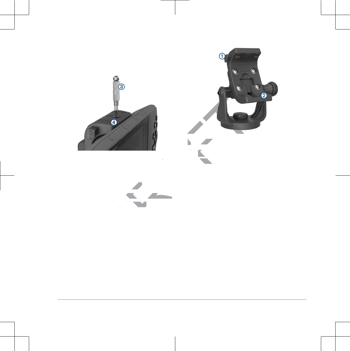
Using the security screw tool, tighten
the security screw ➂ on the top of the
mount ➃.
5HPRYLQJWKH'HYLFHIURP
WKH0RXQW
Loosen the security screw.
Press the button ➀ on the side of the
mount to release the device.
Lift the device out of the mount.
Place the weather cap ➁ on the
cradle.
Important Safety Information 5
DRAFT
RP
rew.rew.
➀
on the side of theon the side of the
e the device.the device.
Lift the device oLift th
Place the wPla
cradle.cradle

DRAFT

DRAFT
Garmin® and the Garmin logo are trademarks of Garmin Ltd. or its subsidiaries, registered in the USA and other countries. These
trademarks may not be used without the express permission of Garmin.
© 2011–2016 Garmin Ltd. or its subsidiaries
Printed in Taiwan
www.garmin.com/support
July 2016
190-02006-92_EN
DRAFT