Garmin 03384 Marine Stereo User Manual
Garmin International Inc Marine Stereo
UserManual.wiki
>
Garmin
>
03384 User Manual
>
User Manual-Installation Instructions 1
Contents
1.
User Manual
2.
Users Manual
3.
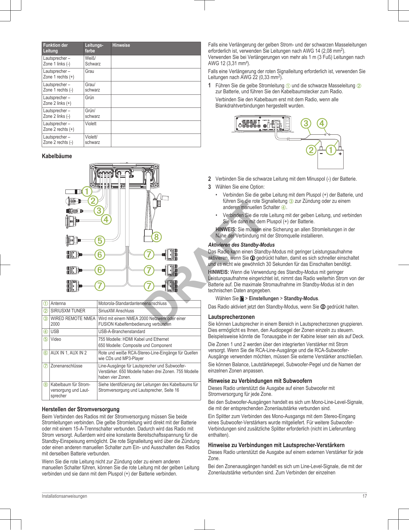
User Manual-Installation Instructions 1
4.
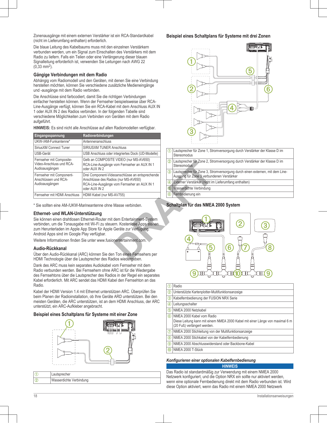
User Manual-Installation Instructions 2
5.
UserMan-statement
User Manual-Installation Instructions 1
Navigation menu
Upload a User Manual
Namespaces
Wiki Guide
HTML
PDF
Info
Views
User Manual
Discussion / Help
Navigation