Garmin GARVHF3 Fixed Mount Class D DSC VHF Marine Radio User Manual 3
Garmin International Inc Fixed Mount Class D DSC VHF Marine Radio 3
Garmin >
Contents
- 1. User Manual 1
- 2. User Manual 2
- 3. User Manual 3
- 4. User Manual 4
User Manual 3
1
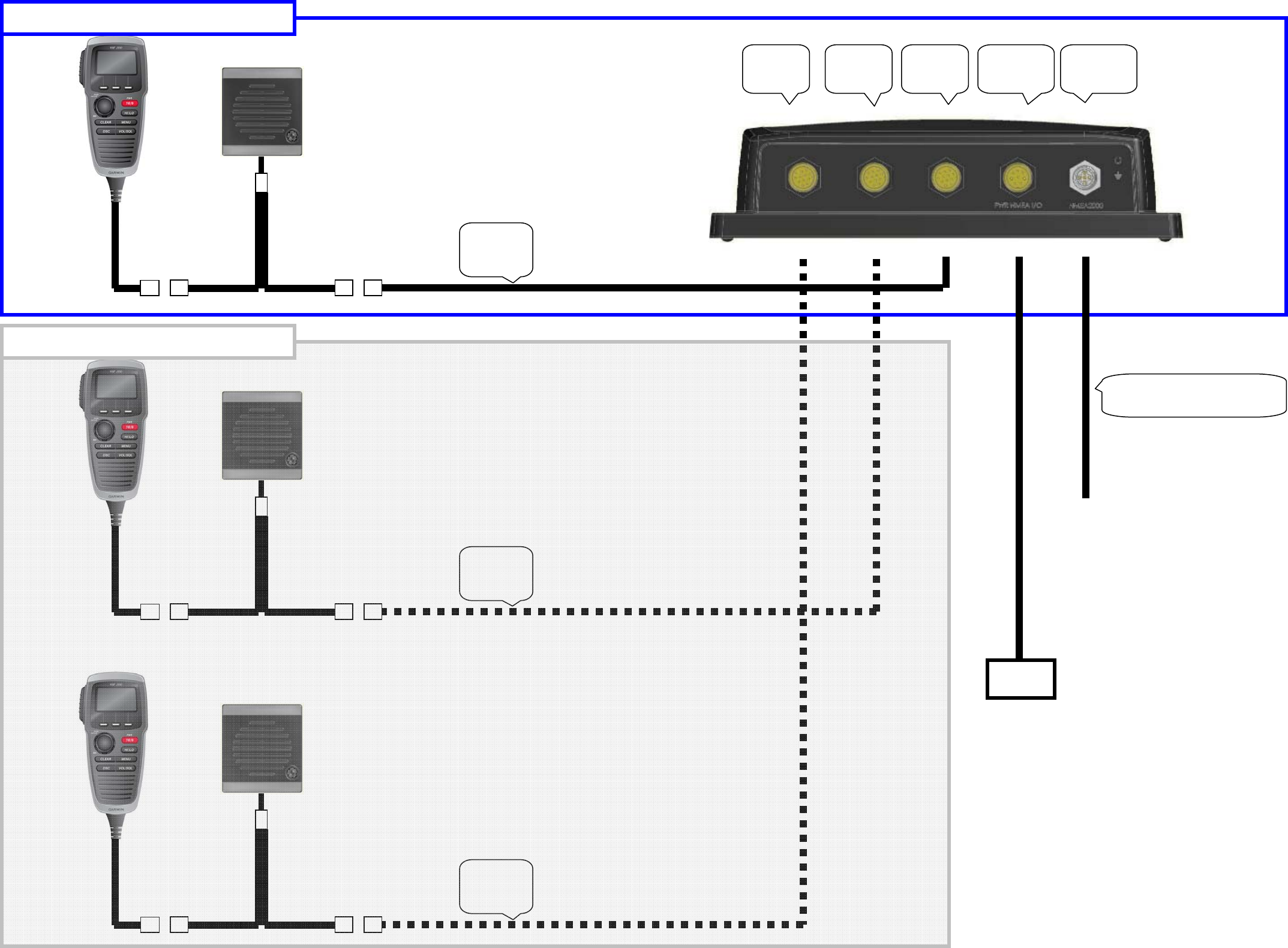
HS1
port
HS2
Port
HS3
port Powe
r
Accessory
port
N
MEA2
k
port
10meter
Extension
Cable
10meter
Extension
Cable
10meter
Extension
Cable
Standard Configuration
Optional Configuration
DC12V
Please use same cable that was
provided for VHF200.
2
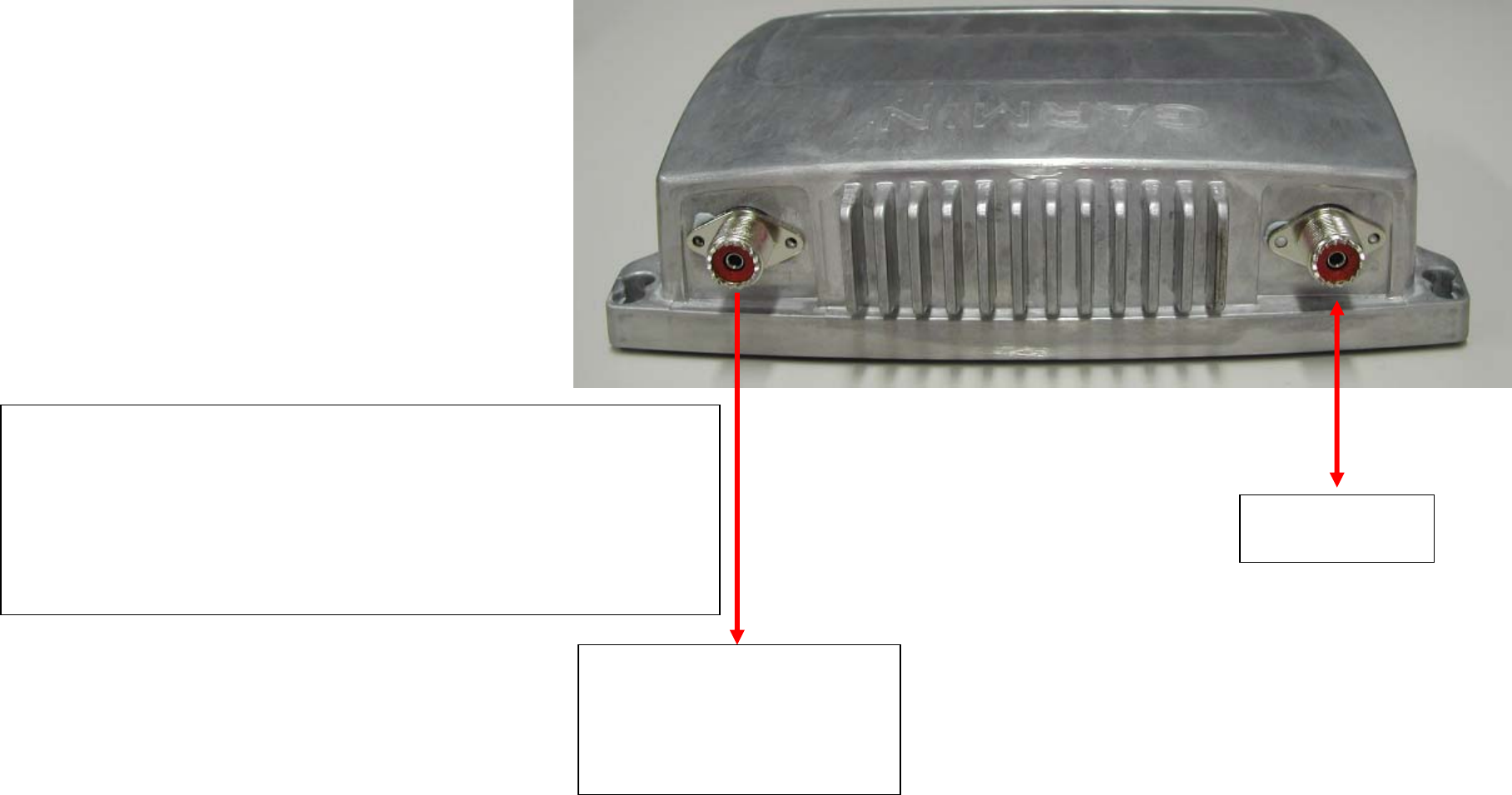
Demodulated DSC signal output port.(Digital signal)
This port is prepared for testing the DSC receiver performance at TUV.
This port is testing purpose only for TUV.
It is not required to connect any equipment when testing EMC.
ANT port.
Bit Error rate meter.
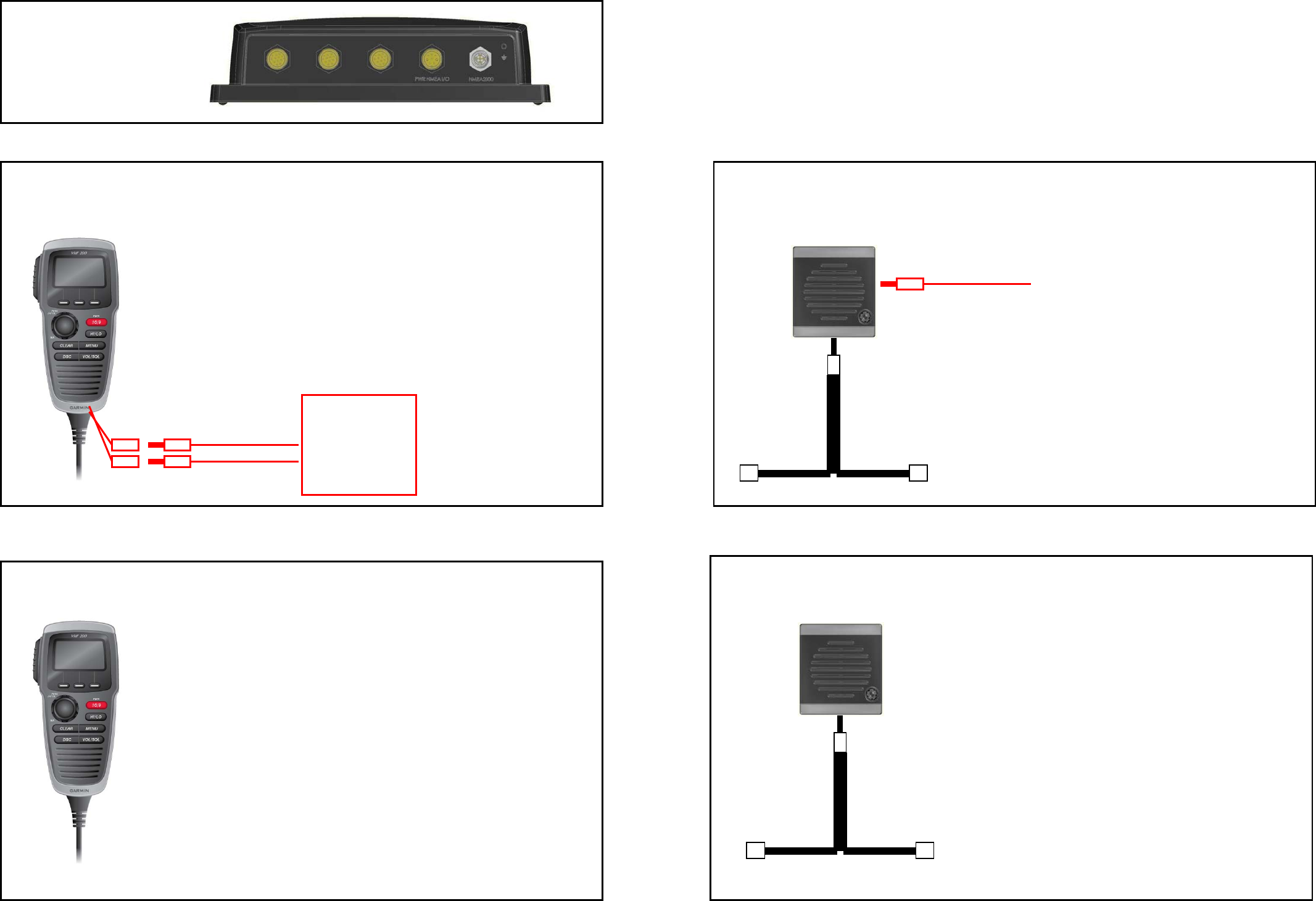
3
Normal Handset
Q’ty : 3 --Note--
Please use normal Handset for EMC TEST.
VHF300 BASE
Q’ty : 3
Handset with Audio input/output terminals
Q’ty : 3 --Note--
Please do not use the Handset which this arrangement was given for EMC TEST.
*22 ohm dummy load is installed instead of speaker.
*Speaker is not active.
*Microphone is not active.
Speaker with Audio output terminals / White resin material
Q’ty : 3 --Note--
Please do not use the Handset which this arrangement was given for EMC TEST.
*4ohm dummy load is installed.
*Speaker will active when un-pluged.
Normal Speaker / White resin material
Q’ty : 3 --Note--
Please use the normal Speaker for EMC TEST.
Items listed below were sent for testing.
JIGfor AFIN/OUT
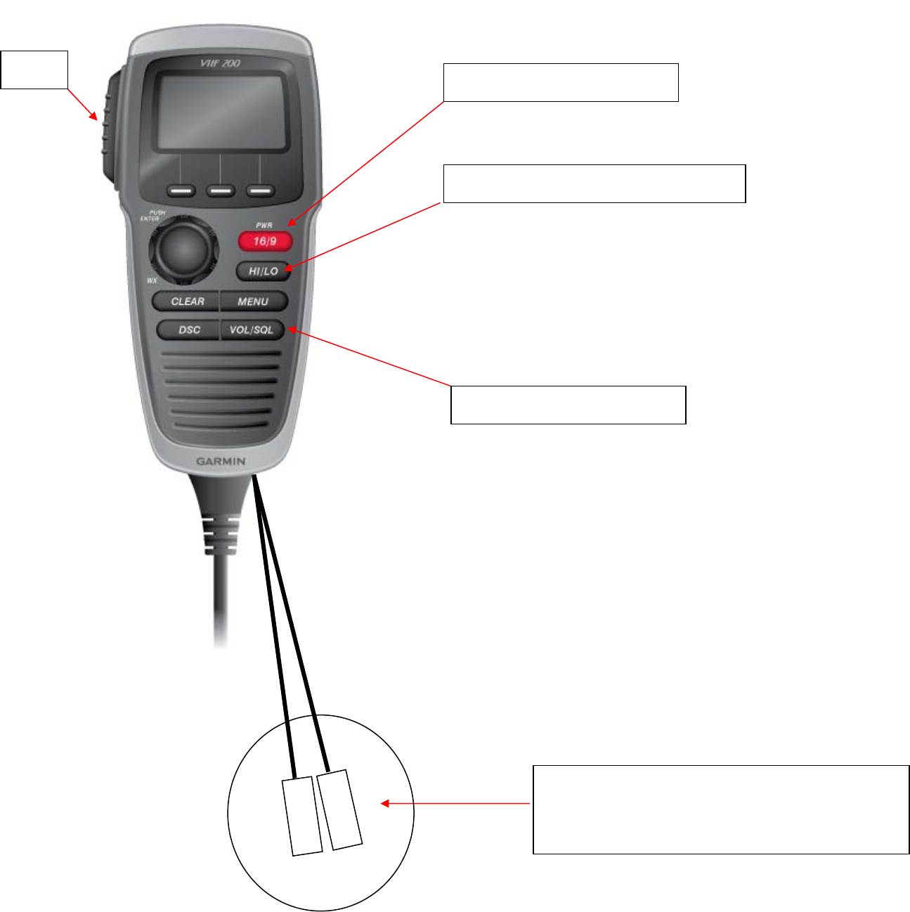
4
1. Press to turn on power.
2. Press and hold to turn off power.
PTT
TX power setting mode.
*Press the Left soft key to select TX power.
1. 1s
t
press to enter Squelch setting.
2. 2nd press to enter Volume setting.
“3.5mm Jac
k
” for Audio input and output.
--Note--
Please do not use the Handset which this arrangement was
given for EMC TEST.
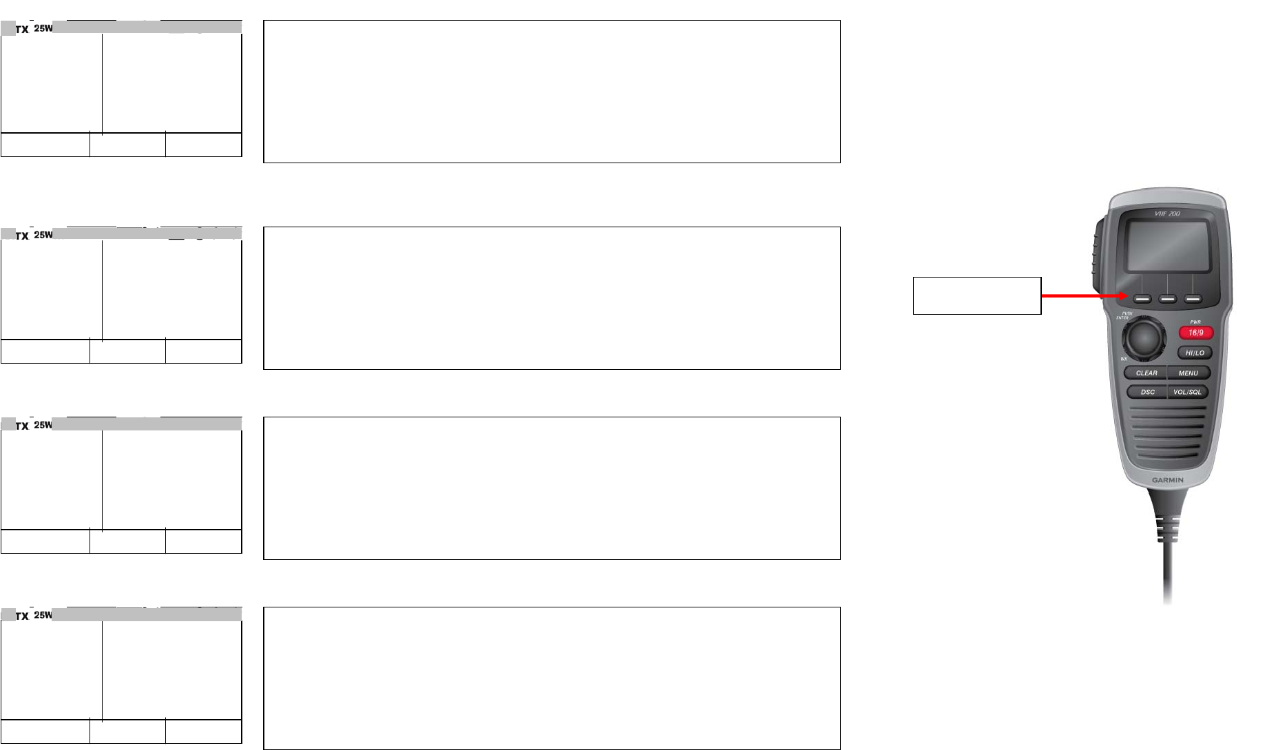
5
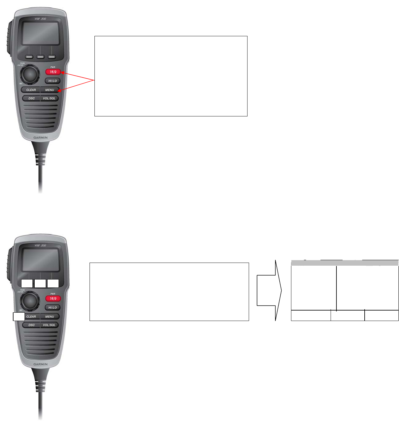
Enter the Test Mode testing the Modulation of DSC .
Step-1. Enter the Test Mode
Step-2 Enter the Key code
1. Turn off power.
2. Press and hold “MENU” + “16”.
3. EUT will ask to enter the key code.
Please enter the Key code as follow.
CLEAR>>Center softkey>>Left softkey>>Right sofykey
Screen will be as right image.
1
2 3 4
01
PRESS OK
LEVEL:050
LO POWER
155.050
+-
6
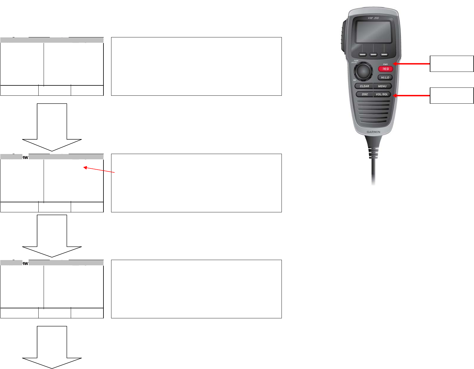
1 Testing of FSK modulation of DSC.
*1.1 Set the EUT to DSC Modulation Test Mode.
continue to the next page
01
PRESS OK
LEVEL:050
LO POWER
155.050
+ -
Press “MENU“ key to set the Test Mode to DSC MOD.
SHUOLD BE “DSC MOD”.!!
Please confirm.
MENU Key
Press “ - “ Soft key to set the channel to 70.
01
PRESS OK
FSK:1300HZ
LEVEL:050
DSC MOD
156.550
FSK + -
“-“ Soft Key
70
PRESS OK
FSK:1300HZ
LEVEL:050
DSC MOD
156.525
FSK + -
Initial screen image of Test Mode.
7
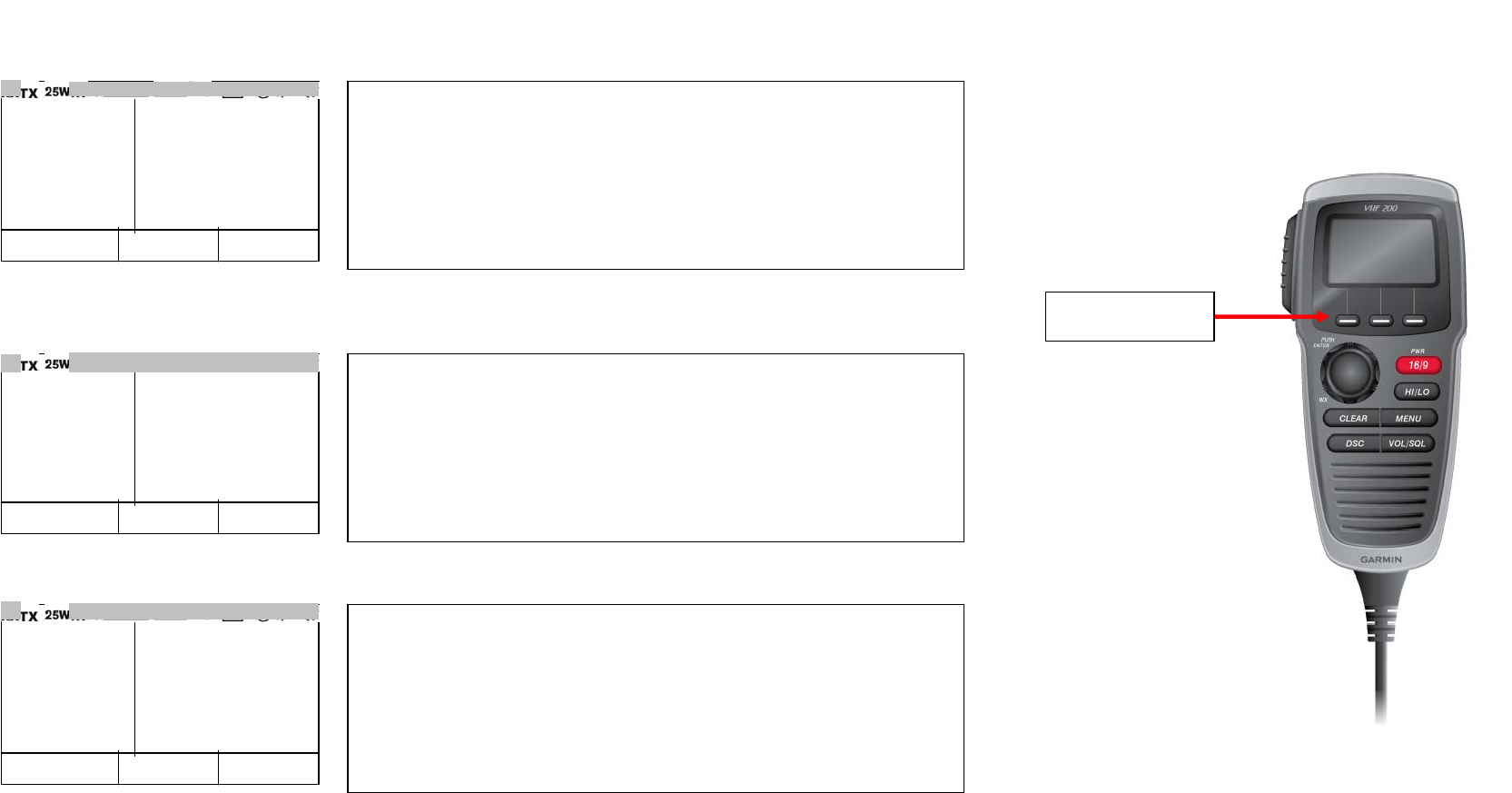
1.2 Testing Y-state / 1300Hz modulation
1.3 Testing B-state / 2100Hz modulation
1.4 Testing continuous Y-state and B-state.
70
PRESS OK
FSK:1300HZ
LEVEL:050
DSC MOD
156.550
FSK + -
1. Press PTT then Y-State / 1300HZ Signal will be transmitted.
Transmit Power will be 25W.
70
PRESS OK
FSK:2100HZ
LEVEL:050
DSC MOD
156.550
FSK + -
1. Press “FS
K
” softkey to change FSK signal to the B-state.
2. Press PTT then B-State / 2100HZ Signal will be transmitted.
Transmit Power will be 25W.
70
PRESS OK
FSK:CONTINU
LEVEL:050
DSC MOD
156.550
FSK + -
1. Press “FS
K
” softkey to change FSK signal to continuous mode.
2. Press PTT then continuous signal will be transmitted.
Transmit Power will be 25W.
“FSK“ Soft Key
Note: Please take a note for frequency set at test mode.
CH70 frequency is set to 156.500MHz at test mode.
CH70 frequency is 156.525 originally. We changed this
frequency setting only for the test because there is possibility to
interfere DSC communication at your area when you conduct this
test longer time ( transmit longer time).
Receiving frequency is set to 156.525.
One of Japanese code less phone influenced DSC frequency recently
in Japan and the unit is recalled. Therefore, we arranged as above
for safety sake.
But, DSC Tx frequency is set to correct frequency (156.525MHz) for actual DSC transmission.
8
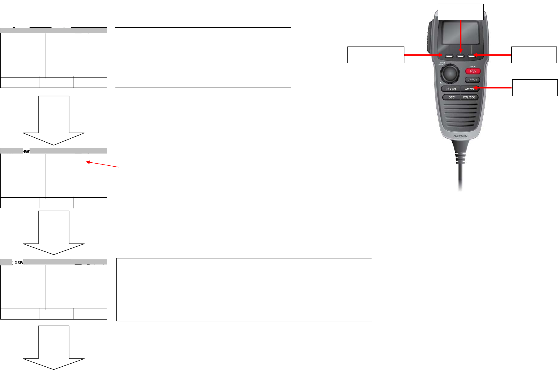
2 Testing of FSK modulation of ATIS.
2.1 Set the EUT to ATIS Modulation Test Mode.
continue to the next page
02
PRESS OK
FSK:1300HZ
LEVEL:050
ATIS MOD
156.800
FSK + -
Press “+“or “-“ soft key to change the channel to CH01,CH02 or CH03.
Frequency of the Test Mode Channels are as follow.
CH01 : 156.050MHz
CH02 : 156.800MHz
CH03 : 157.425MHz
01
PRESS OK
LEVEL:050
LO POWER
155.050
+ -
Press “MENU“ key to set the Test Mode to ATIS MOD.
SHUOLD BE “ATIS MOD”.!!
Please confirm.
MENU Key
01
PRESS OK
FSK:1300HZ
LEVEL:050
ATIS MOD
156.550
FSK + -
“-“ Soft Key
Initial screen image of Test Mode.
“+“ Soft Key
“FSK“ Soft Key
9
2.2 Testing Y-state / 1300Hz modulation
2.3 Testing B-state / 2100Hz modulation
2.4 Testing continuous Y-state and B-state.
2.5 Testing ATIS transmission.
02
PRESS OK
FSK:1300HZ
LEVEL:050
ATIS MOD
156.800
FSK + -
2. Press PTT then Y-State / 1300HZ Signal will be transmitted.
Transmit Power will be 25W.
02
PRESS OK
FSK:2100HZ
LEVEL:050
ATIS MOD
156.800
FSK + -
1. Press “FS
K
” softkey to change FSK signal to the B-state.
2. Press PTT then B-State / 2100HZ Signal will be transmitted.
Transmit Power will be 25W.
02
PRESS OK
FSK:CONTINU
LEVEL:050
ATIS MOD
156.800
FSK + -
1. Press “FS
K
” softkey to change FSK signal to continuous mode.
2. Press PTT then continuous signal will be transmitted.
Transmit Power will be 25W.
02
PRESS OK
FSK:ATIS TX
LEVEL:050
ATIS MOD
156.800
FSK + -
1. Press “FS
K
” softkey to change FSK signal to ATIS TX mode.
2. Press PTT then Y-State signal will be transmitted for 10 seconds.
Transmit Power will be 25W.
“FSK“ Soft Key