GemTek Technology CISCO867VAE XDSL Router User Manual HIG880 860
Gemtek Technology Co., Ltd. XDSL Router HIG880 860
Contents
User Manual Part 2
CHAPTER
2-1
Cisco 860 Series, Cisco 880 Series, and Cisco 890 Series Integrated Services Routers Hardware Installation Guide
OL-16215-10
2
Installing the Router
This chapter describes the equipment and the procedures for successfully installing the Cisco 860 series,
880 series, and 890 series Integrated Services Routers (ISRs), and contains the following sections:
• Equipment, Tools, and Connections, page 2-2
• Installing the Router, page 2-3
Note For compliance and safety information, see the Regulatory Compliance and Safety Information
Roadmap that ships with the router and the Regulatory Compliance and Safety Information for Cisco 800
Series and SOHO Series Routers.
Warning
All wireless LAN products in the 5.2/5.3GHz band cannot be used outdoors. Use the product only
indoors.
Statement 372
Warning
Read the installation instructions before connecting the system to the power source.
Statement 1004
Warning
Only trained and qualified personnel should be allowed to install, replace, or service this equipment.
Statement 1030
Warning
Ultimate disposal of this product should be handled according to all national laws and regulations.
Statement 1040
Warning
Do not locate the antenna near overhead power lines or other electric light or power circuits, or
where it can come into contact with such circuits. When installing the antenna, take extreme care
not to come into contact with such circuits, because they may cause serious injury or death. For
proper installation and grounding of the antenna, please refer to national and local codes (for
example, U.S.:NFPA 70, National Electrical Code, Article 810, Canada: Canadian Electrical Code,
Section 54).
Statement 1052
Warning
No user-serviceable parts inside. Do not open.
Statement 1073
2-2
Cisco 860 Series, Cisco 880 Series, and Cisco 890 Series Integrated Services Routers Hardware Installation Guide
OL-16215-10
Chapter 2 Installing the Router
Equipment, Tools, and Connections
Equipment, Tools, and Connections
This section describes the equipment, tools, and connections necessary for installing your Cisco 860
series, 880 series, and 890 series ISRs. It contains the following topics:
• Items Shipped with your Router, page 2-2
• Additional Items, page 2-2
• Connections, page 2-3
• Ethernet Devices, page 2-3
Items Shipped with your Router
Unpack the box and verify that all items listed on the invoice were shipped with the router.
Table 2-1 lists the items and their quantities that are shipped with each router model.
Additional Items
The following items are not shipped with the router but are required for installation:
• ESD-preventive cord and wrist strap.
• Screws for mounting the router on a wall:
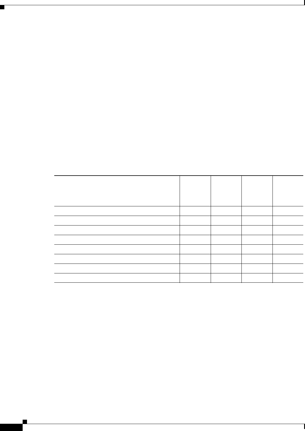
Ta b l e 2-1 Items and Their Quantities That Are Shipped with the Cisco 860 Series, Cisco 880
Series, and Cisco 890 Series ISRs
Item
Cisco 860
Series
Routers
Cisco
860VAE
Series
Routers1
1. By default, no cables are shipped with Cisco 860VAE models unless requested through the dynamic configuration tool.
Cisco 880
Series
Routers
Cisco 890
Series
Routers
Straight-through RJ-45 Ethernet cable 1 — 1 1
ADSL RJ-11-to-RJ-11 straight-through cable ———1
RJ-11 DSL2 cable
2. DSL = digital subscriber line.
13
3. Shipped with Cisco 867 models only.
n/a 14
4. Shipped with Cisco 886, 887, 887M, and 886-J models only.
1
DSL RJ-45-to-dual-RJ-11 breakout cable —n/a 15
5. Shipped with Cisco 888E models only.
1
RJ-45-to-DB-9 console cable 1 — 1 1
External 12 VDC power supply adapter 1111
AC power supply cable with cable retention clip 1111
Cisco Configuration Professional (Cisco CP) CD6
6. Cisco CP is optional by order and available only on some SKUs.
1111

2-3
Cisco 860 Series, Cisco 880 Series, and Cisco 890 Series Integrated Services Routers Hardware Installation Guide
OL-16215-10
Chapter 2 Installing the Router
Installing the Router
–
Two number-10 wood screws (round- or pan-head) with number-10 washers, or two number-10
washer-head screws, for mounting on a wall stud. The screws must be long enough to penetrate
at least 3/4 in. (20 mm) into the supporting wood or metal wall stud.
–
Two number-10 wall anchors with washers, for mounting the router on a hollow-wall.
• Wire crimper for chassis grounding.
• Wire for connecting the chassis to an earth ground:
–
AWG 14 (2 mm2) or larger wire for NEC-compliant chassis grounding.
–
AWG 18 (1 mm2) or larger wire for EN/IEC 60950–compliant chassis grounding.
• Ring terminal with an inner diameter of 1/4 in. (5 to 7 mm), for NEC-compliant chassis grounding.
• Ethernet cables for connecting to the Fast Ethernet (FE) WAN and LAN ports.
Connections
Obtain a broadband or Ethernet connection from your service provider.
Ethernet Devices
Identify the Ethernet devices that you will connect to the router: hub, servers, and workstations or PCs.
Ensure that each device has a network interface card (NIC) for connecting to Ethernet ports.
• If you plan to configure the software using Cisco IOS commands through the console port, provide
an ASCII terminal or a PC that is running terminal emulation software to connect to the console port.
• If you plan to connect a modem, provide the modem and modem cable.
• If you plan to use the Data BRI port, provide an NT1 device and an ISDN S/T cable.
• If you plan to use the cable-lock feature, provide a Kensington or equivalent locking cable.
Installing the Router
This section describes how to install the Cisco 860 series, 880 series, and 890 series ISRs. These routers
can either be installed on a table top or other flat horizontal surface or be mounted on a wall. The
Cisco 890 series ISRs may be mounted in a rack. This section also describes how to attach WLAN
antennas to the Cisco 890 series routers. This section contains the following topics:
• Warnings, page 2-4
• Installing Antennas, page 2-4
• Installing on a Table, page 2-7
• Mounting on a Wall, page 2-8
• Installing in a Rack, page 2-11
• Installing the Router Ground Connection, page 2-13
• Installing the FIPS Cover, page 2-14
2-4
Cisco 860 Series, Cisco 880 Series, and Cisco 890 Series Integrated Services Routers Hardware Installation Guide
OL-16215-10
Chapter 2 Installing the Router
Installing the Router
Warnings
Warning
This equipment needs to be grounded. Use a green and yellow 12 to 14 AWG ground wire to connect
the host to earth ground during normal use.
Statement 242
Warning
This equipment must be grounded. Never defeat the ground conductor or operate the equipment in the
absence of a suitably installed ground conductor. Contact the appropriate electrical inspection
authority or an electrician if you are uncertain that suitable grounding is available.
Statement 1024
Warning
Read the wall-mounting instructions carefully before beginning installation. Failure to use the
correct hardware or to follow the correct procedures could result in a hazardous situation to people
and damage to the system.
Statement 378
Note • Do not stack anything on top of the router.
• Do not cover or obstruct the router vents located on both sides and top of the routers; otherwise,
overheating could occur and cause damage to the router.
• Place router in ventilated area to avoid local air heating.
Caution Do not cover or obstruct the router vents located on both sides of the router; otherwise, overheating could
occur and cause damage to the router.
Caution Do not place anything on top of the router that weighs more than 10 pounds (4.5 kilograms), and do not
stack routers on a desktop. Excessive weight on top of the router could damage the chassis.
Caution Do not install the router or power supplies next to a heat source of any kind, including heating vents.
Caution The top surface of the router is hot since heat is dissipated through the top. Do not keep any object in
direct contact with the surface for a prolonged period.
Installing Antennas
The Cisco 890 series wireless routers have three reverse-polarity threaded Neill-Concelman (RP-TNC)
connectors on the back panel. The antennas that are shipped with the router are dual-band 2.4-GHz to
5-GHz omnidirectional dipole antennas.
2-5
Cisco 860 Series, Cisco 880 Series, and Cisco 890 Series Integrated Services Routers Hardware Installation Guide
OL-16215-10
Chapter 2 Installing the Router
Installing the Router
Warning
All wireless LAN products in the 5.2/5.3GHz band cannot be used outdoors. Use the product only
indoors.
Statement 372
Note Before you install the Cisco 890 series wireless router on a table, wall, or rack, connect the antennas to
the back panel. It is difficult to attach the antennas after the router is installed.
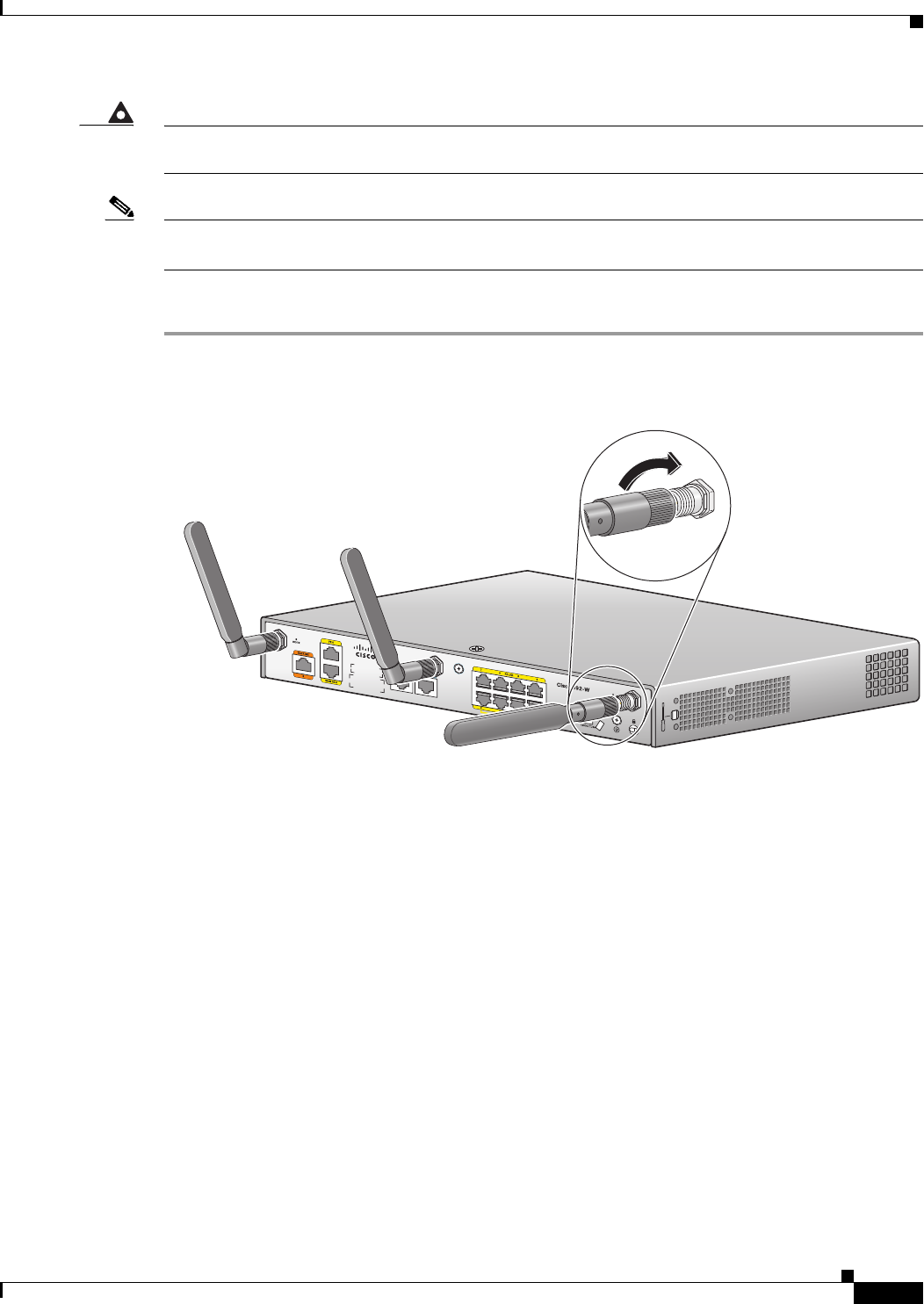
To attach the radio antennas to your wireless router, follow these steps:
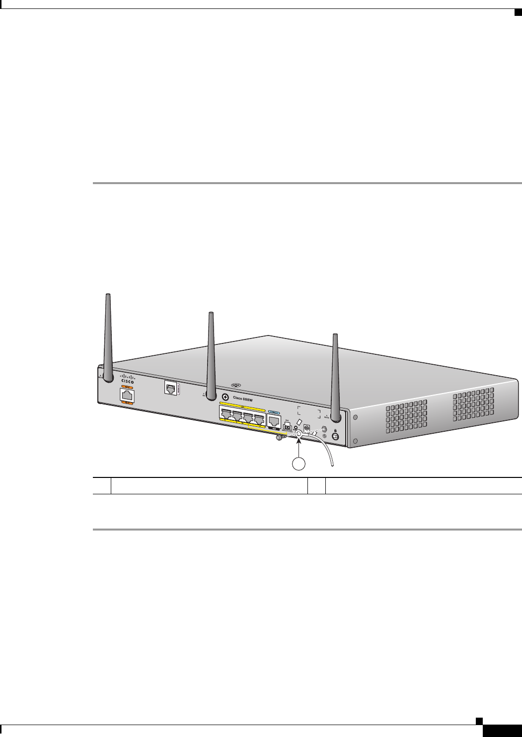
Step 1 Manually screw the antennas tight to the RP-TNC connectors on the back of the router.
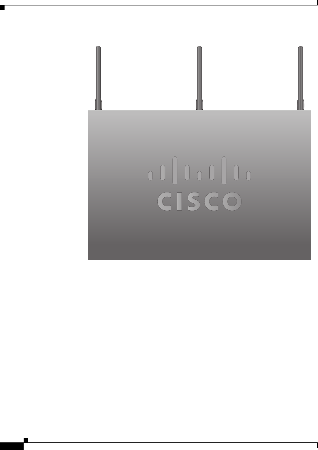
Figure 2-1 Attaching Antennas to the Router
Step 2 Orient the antennas. For optimum wireless performance, the antennas should be perpendicular with
respect to the floor.
a. If the router is being mounted on a desk, orient the antennas straight up.
b. If the router is being mounted on a wall, orient the antennas perpendicular to the floor, as shown in
Figure 2-2 and Figure 2-3.
272486
2-6
Cisco 860 Series, Cisco 880 Series, and Cisco 890 Series Integrated Services Routers Hardware Installation Guide
OL-16215-10
Chapter 2 Installing the Router
Installing the Router
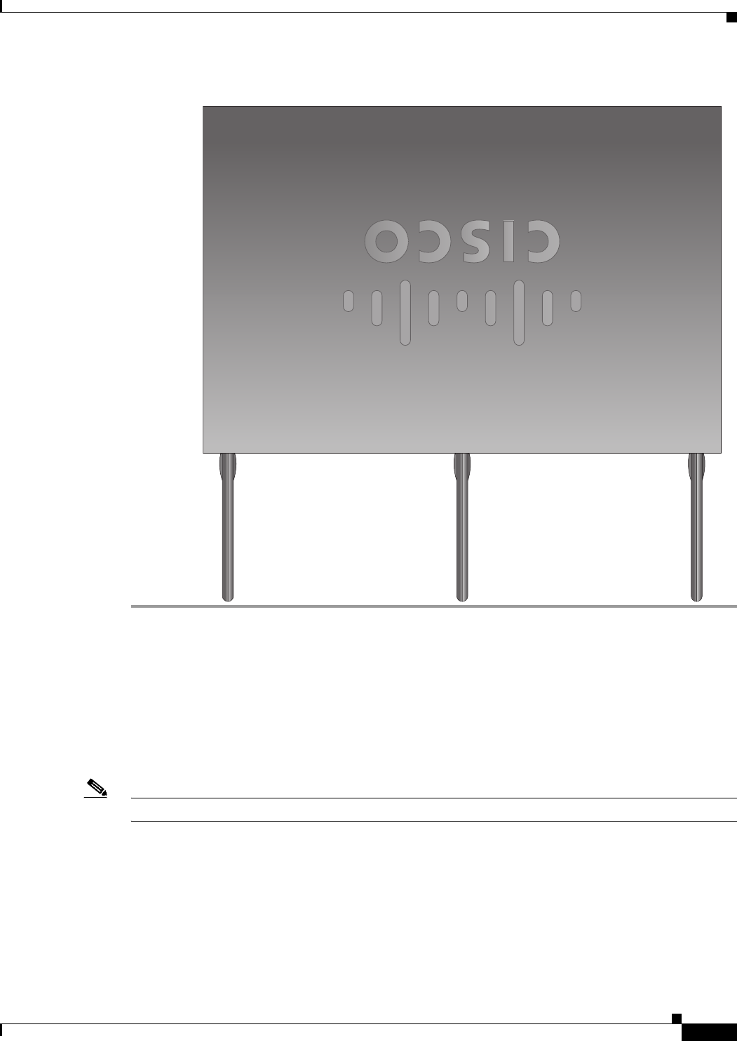
Figure 2-2 Antennas Oriented Vertically Up
274774
2-7
Cisco 860 Series, Cisco 880 Series, and Cisco 890 Series Integrated Services Routers Hardware Installation Guide
OL-16215-10
Chapter 2 Installing the Router
Installing the Router
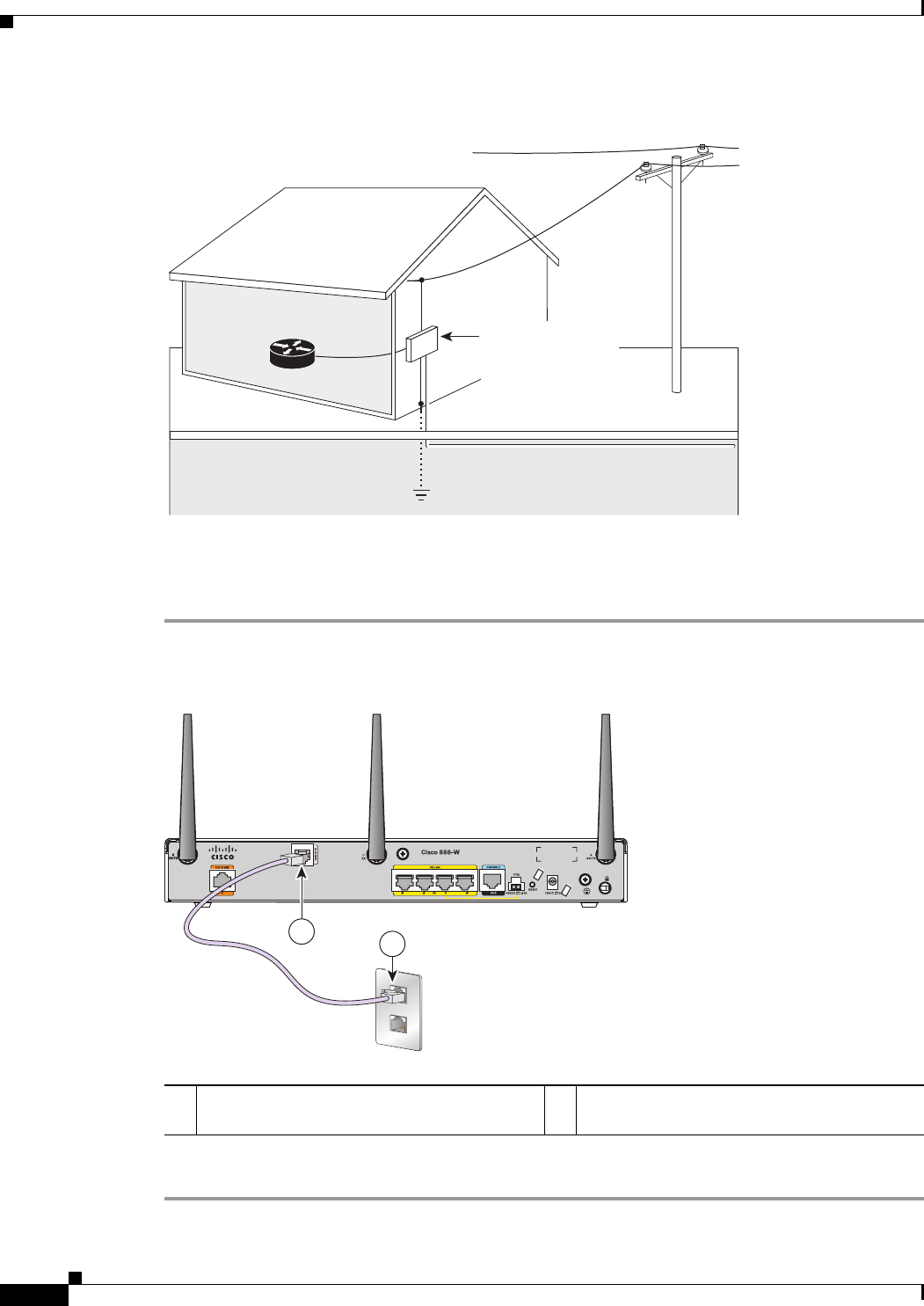
Figure 2-3 Antennas Oriented Vertically Down
Installing on a Table
To install the router on a table or other flat horizontal surface, firmly place the router on a table or other
horizontal surface. Keep at least 1 inch (2.5 cm) of clear space beside the cooling inlet and exhaust vents.
Connect the chassis to a reliable earth ground. For the chassis ground connection procedures, see the
“Installing the Router Ground Connection” section on page 2-13.
Note Do not place anything on top of the router.
274775

2-8
Cisco 860 Series, Cisco 880 Series, and Cisco 890 Series Integrated Services Routers Hardware Installation Guide
OL-16215-10
Chapter 2 Installing the Router
Installing the Router
Mounting on a Wall
The Cisco 860 series, 880 series, and 890 series ISRs have mounting holes on the bottom of the chassis
for mounting the unit on a wall or other vertical surface.
The mounting holes are bidirectional. You can hang the router with the front bezel facing upward or
downward.
Keep at least 1 inch (2.5 cm) of clear space beside the cooling inlet and exhaust vents.
Tip When choosing a location for wall-mounting the router, consider cable limitations and wall structure.
To mount the router on a wall, follow these steps:
Step 1 Determine the required distance between mounting holes on the router. Figure 2-4 shows the wall-mount
holes located on the underside of the router.
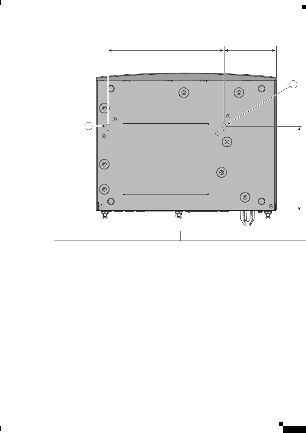
Note For most router models, the distance between mounting holes is 8.2 inches (208 mm), as shown
in Figure 2-4. For the Cisco 866 and Cisco 867 models, the distance is 7.85 inches (199 mm).
Verify the required distance before drilling the holes.
2-9
Cisco 860 Series, Cisco 880 Series, and Cisco 890 Series Integrated Services Routers Hardware Installation Guide
OL-16215-10
Chapter 2 Installing the Router
Installing the Router
Figure 2-4 Wall-mount Holes on the Underside of the Router
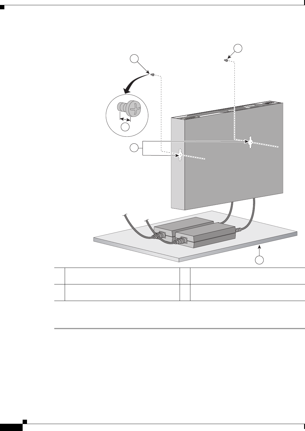
Step 2 Insert the screws, with anchors, into the wall. Leave 1/8 inch (0.32 cm) between the screw head and the
wall. See Figure 2-5.
Step 3 Hang the router on the screw without forcibly pushing towards the wall side. The screw head may
damage the protection wall inside. Place the power adapter on a nearby horizontal surface. See
Figure 2-5.
1Wall-mount holes
231987
1
3.673 in.8.200 in.
5.961 in.
1
2-10
Cisco 860 Series, Cisco 880 Series, and Cisco 890 Series Integrated Services Routers Hardware Installation Guide
OL-16215-10
Chapter 2 Installing the Router
Installing the Router
Figure 2-5 Router Mounted on the Wall
Step 4 Connect the chassis to a reliable earth ground. For the chassis ground connection procedures, see the
“Installing the Router Ground Connection” section on page 2-13.
1Two number-10 wood screws mounted on the
wall
3Horizontal surface on which to place the
power adapter
2Wall-mount holes 4Distance between the screw head and the wall,
1/8 in. (0.32 cm)
231982
4
2
1
1
3
2-11
Cisco 860 Series, Cisco 880 Series, and Cisco 890 Series Integrated Services Routers Hardware Installation Guide
OL-16215-10
Chapter 2 Installing the Router
Installing the Router
Installing in a Rack
The Cisco 890 series ISRs can be mounted in a rack. To install a Cisco 890 series ISR in a rack, follow
these steps:
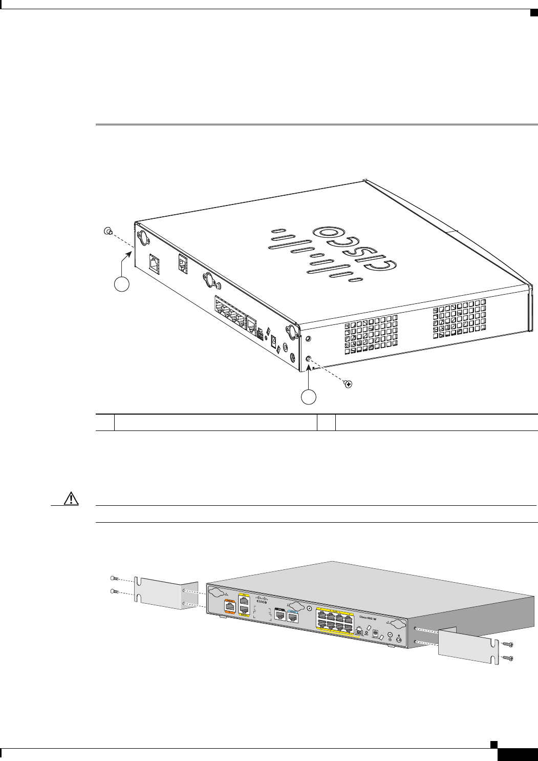
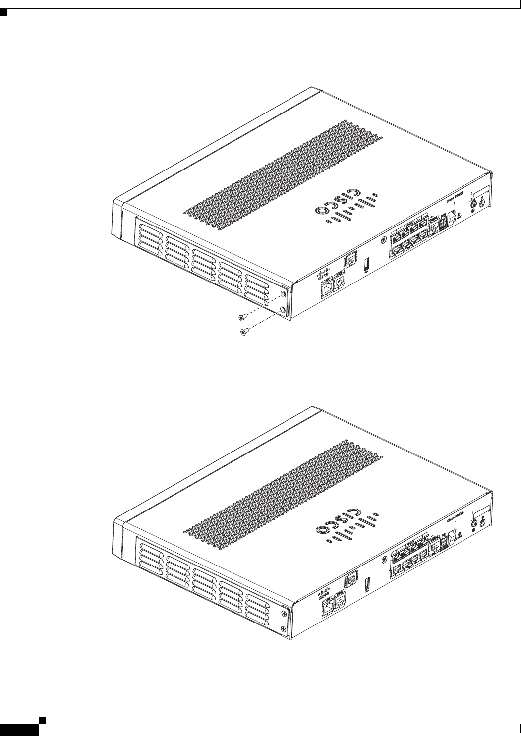
Step 1 Remove the screws, as shown in Figure 2-6.
Figure 2-6 Screw Locations
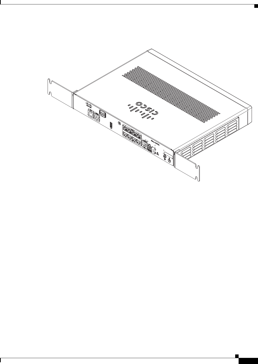
Step 2 Using the screws provided, attach the rack-mount brackets to the Cisco 890 series ISR chassis, as shown
in Figure 2-7. Use two screws on each side. Use a number 2 Phillips screwdriver to install the bracket
screws on both sides of the chassis.
Caution Do not over torque the screws. The recommended torque is 6 to 8 in-lb (0.7 to 0.9 N-m).
Figure 2-7 Attaching the Rack-mount Brackets to the Cisco 890 Series ISR
1Screws
278159
1
1
272484

2-12
Cisco 860 Series, Cisco 880 Series, and Cisco 890 Series Integrated Services Routers Hardware Installation Guide
OL-16215-10
Chapter 2 Installing the Router
Installing the Router
Caution Chassis installation must allow unrestricted airflow for chassis cooling.
Step 3 Using two screws for each side (supplied with the rack), attach the Cisco 890 series ISR with rack-mount
brackets to a 19-inch rack. Start with the lower pair of screws first, resting the brackets on the lower
screws while you insert the upper pair of screws.
Note Be sure to leave space above and below each unit in a rack to allow for cooling air circulation.
Note Do not stack equipment directly above the router. Keep at least 1 rack unit of space above the
router.
Tip The screw slots in the brackets are spaced to line up with every second pair of screw holes in the
rack. When the correct screw holes are used, the small threaded holes in the brackets line up with
unused screw holes in the rack. If the small holes do not line up with the rack holes, you must
raise or lower the brackets to the next rack hole.
Step 4 Place the power adapter on a nearby horizontal surface.
Step 5 Connect the chassis to a reliable earth ground. For the chassis ground connection procedures, see the
“Installing the Router Ground Connection” section on page 2-13.
Warning
To prevent bodily injury when mounting or servicing this unit in a rack, you must take special
precautions to ensure that the system remains stable. The following guidelines are provided to
ensure your safety:
• This unit should be mounted at the bottom of the rack if it is the only unit in the rack.
• When mounting this unit in a partially filled rack, load the rack from the bottom to the top with the heaviest
component at the bottom of the rack.
• If the rack is provided with stabilizing devices, install the stabilizers before mounting or servicing the unit in
the rack.
Statement 1006
2-13
Cisco 860 Series, Cisco 880 Series, and Cisco 890 Series Integrated Services Routers Hardware Installation Guide
OL-16215-10
Chapter 2 Installing the Router
Installing the Router
Installing the Router Ground Connection
The router must be connected to a reliable earth ground. Install the ground wire in accordance with local
electrical safety standards.
• For NEC-compliant grounding, use size 14 AWG (2 mm2) or larger copper wire and a ring terminal
with an inner diameter of 1/4 in. (5 to 7 mm).
• For EN/IEC 60950–compliant grounding, use size 18 AWG (1 mm2) or larger copper wire.
To install the ground connection, follow these steps:
Step 1 Strip one end of the ground wire to the length required for the ground lug or terminal.
Step 2 Crimp the ground wire to the ground lug or ring terminal, using the wire crimper.
Step 3 Attach the ground lug or ring terminal to the chassis, as shown in Figure 2-8. For a ground lug, use the
two provided screws with captive locking washers. For a ring terminal, use one of the screws provided.
Tighten the screws to a torque of 8 to 10 in-lb (0.9 to 1.1 N-m).
Figure 2-8 Chassis Ground Connection Using Ring Terminal
Step 4 Connect the other end of the ground wire to a known reliable earth ground point at your site.
After you install and properly ground the router, you can connect the power wiring, the WAN and LAN
cables, and the cables for administrative access as required for your installation.
1Ring terminal
231981
1
2-14
Cisco 860 Series, Cisco 880 Series, and Cisco 890 Series Integrated Services Routers Hardware Installation Guide
OL-16215-10
Chapter 2 Installing the Router
Installing the Router
Installing the FIPS Cover
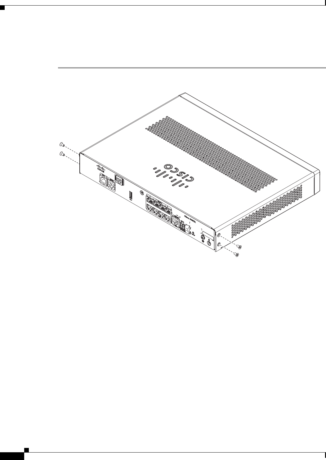
Perform the following steps to install the FIPS cover in the router:
Step 1 Remove the four mounting screws of the top cover.
284921
2-15
Cisco 860 Series, Cisco 880 Series, and Cisco 890 Series Integrated Services Routers Hardware Installation Guide
OL-16215-10
Chapter 2 Installing the Router
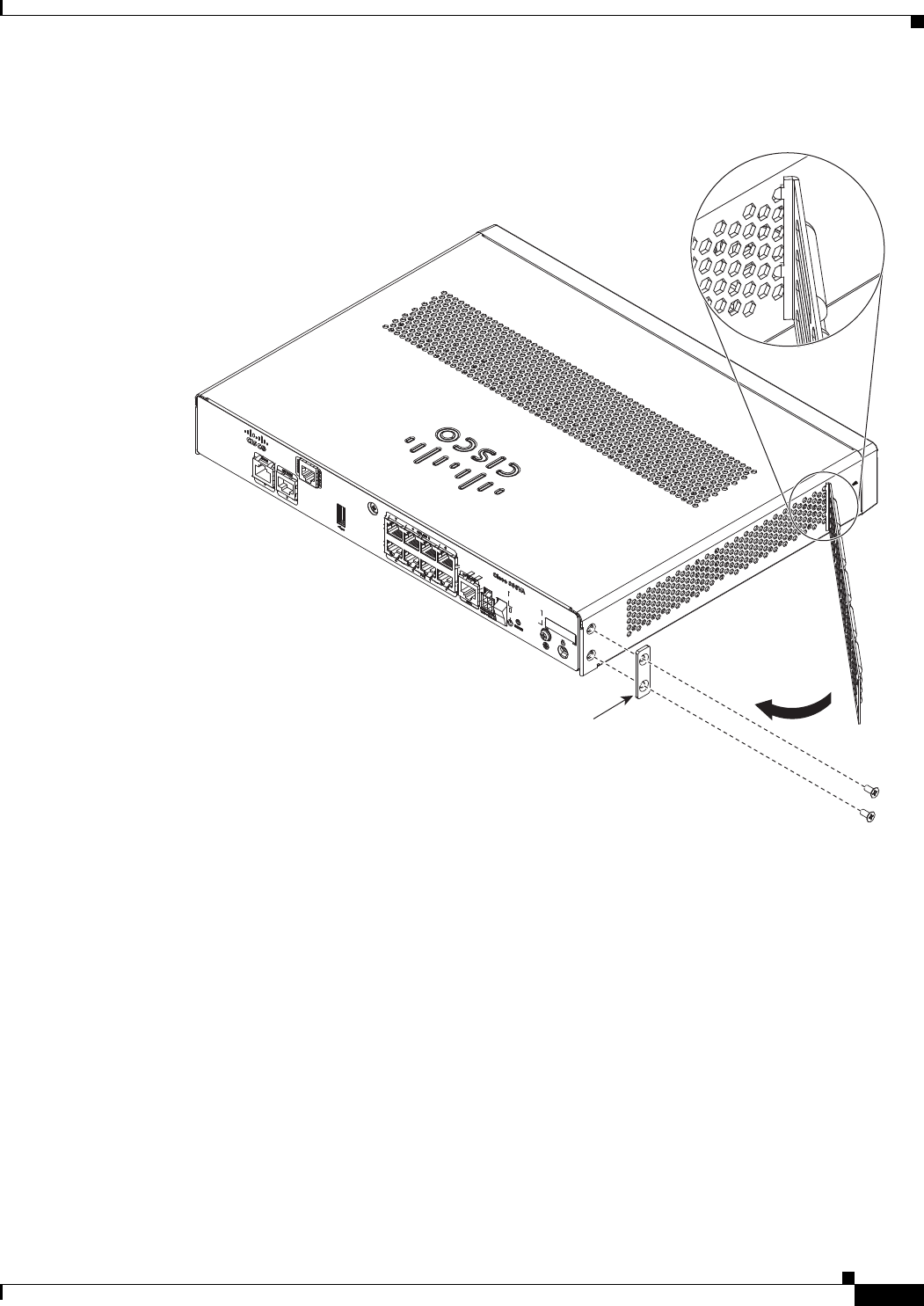
Installing the Router
Step 2 Install the left-side FIPS cover, as shown in detail A.
Step 3 Rotate and bring into the close position to hinge to the correct hexagon.
Step 4 Place the adapter plate before closing by aligning the mounting holes.
284922
Detail A
Adapter
Plate
2-16
Cisco 860 Series, Cisco 880 Series, and Cisco 890 Series Integrated Services Routers Hardware Installation Guide
OL-16215-10
Chapter 2 Installing the Router
Installing the Router
Step 5 Secure the FIPS cover with two mounting screws.
Step 6 Install the right-side FIPS cover the same way as the left-side FIPS cover.
Step 7 View after both covers are installed.
284923
284924
2-17
Cisco 860 Series, Cisco 880 Series, and Cisco 890 Series Integrated Services Routers Hardware Installation Guide
OL-16215-10
Chapter 2 Installing the Router
Installing the Router
Step 8 If the FIPS covers are installed with the rack mount brackets, the adapter plates are not required in the
installation.
284925

2-18
Cisco 860 Series, Cisco 880 Series, and Cisco 890 Series Integrated Services Routers Hardware Installation Guide
OL-16215-10
Chapter 2 Installing the Router
Installing the Router

CHAPTER
3-1
Cisco 860 Series, Cisco 880 Series, and Cisco 890 Series Integrated Services Routers Hardware Installation Guide
OL-16215-10
3
Connecting the Router
This chapter describes how to connect Cisco 860 series, Cisco 880 series, and Cisco 890 series
Integrated Services Routers (ISRs) to Ethernet devices, Power over Ethernet (PoE), and a network. The
chapter contains the following sections:
• Safety Warnings, page 3-2
• Preparing to Connect the Router, page 3-4
• Connecting a PC, Server, or Workstation, page 3-5
• Connecting a Phone, page 3-6
• Connecting an External Ethernet Switch, page 3-7
• Connecting the V.92 modem Port, page 3-8
• Connecting a Terminal or PC to the Console Port, page 3-9
• Connecting a Modem to the Auxiliary Port, page 3-10
• Connecting the 3G Card, page 3-11
• Installing the 3G Adapter for Extended Cable/Antenna, page 3-17
• Connecting a Data BRI Port, page 3-21
• Connecting an FE Line to an FE WAN Port, page 3-23
• Connecting a GE Line to an GE WAN Port, page 3-24
• Connecting an xDSL Line, page 3-25
• Connecting Power over Ethernet, page 3-27
• Connecting the AC Adapter, page 3-28
• Connecting an FXS Line, page 3-32
• Connecting an FXO Line, page 3-34
• Connecting a Voice ISDN BRI Line, page 3-35
• Connecting a Small Form-Factor Pluggable Module, page 3-37
• Verifying Connections, page 3-40
Note For compliance and safety information, see Regulatory Compliance and Safety Information Roadmap
that ships with the router and Regulatory Compliance and Safety Information for Cisco 800 Series and
SOHO Series Routers.
3-2
Cisco 860 Series, Cisco 880 Series, and Cisco 890 Series Integrated Services Routers Hardware Installation Guide
OL-16215-10
Chapter 3 Connecting the Router
Safety Warnings
Note The illustrations in this chapter show a wireless router with antennas attached. Non-wireless routers do
not have antennas or antenna connectors on the back panel. However, the procedures for connecting
devices to the router are the same for both wireless and non-wireless routers.
Note Depending on the features available for your router, some content in this chapter may not apply to your
router.
Safety Warnings
Warning
When installing the product, please use the provided or designated connection cables/power
cables/AC adaptors/batteries. Using any other cables/adaptors could cause a malfunction or a fire.
Electrical Appliance and Material Safety Law prohibits the use of UL-certified cables (that have the
“UL” or “CSA” shown on the cord), not regulated with the subject law by showing “PSE” on the cord,
for any other electrical devices than products designated by CISCO.
Statement 371
Warning
Do not work on the system or connect or disconnect cables during periods of lightning activity.
Statement 1001
Warning
This equipment has been designed for connection to TN and IT power systems.
Statement 1007
Warning
There is the danger of explosion if the battery is replaced incorrectly. Replace the battery only with
the same or equivalent type recommended by the manufacturer. Dispose of used batteries according
to the manufacturer’s instructions.
Statement 1015
Warning
Take care when connecting units to the supply circuit so that wiring is not overloaded.
Statement 1018
Warning
To avoid electric shock, do not connect safety extra-low voltage (SELV) circuits to telephone-network
voltage (TNV) circuits. LAN ports contain SELV circuits, and WAN ports contain TNV circuits. Some
LAN and WAN ports both use RJ-45 connectors. Use caution when connecting cables.
Statement 1021
Warning
Hazardous network voltages are present in WAN ports regardless of whether power to the unit is OFF
or ON. To avoid electric shock, use caution when working near WAN ports. When detaching cables,
detach the end away from the unit first.
Statement 1026
Warning
Only trained and qualified personnel should be allowed to install, replace, or service this equipment.
Statement 1030
3-3
Cisco 860 Series, Cisco 880 Series, and Cisco 890 Series Integrated Services Routers Hardware Installation Guide
OL-16215-10
Chapter 3 Connecting the Router
Safety Warnings
Warning
Do not use this product near water; for example, near a bath tub, wash bowl, kitchen sink or laundry
tub, in a wet basement, or near a swimming pool.
Statement 1035
Warning
Never install telephone jacks in wet locations unless the jack is specifically designed for wet
locations.
Statement 1036
Warning
Never touch uninsulated telephone wires or terminals unless the telephone line has been
disconnected at the network interface.
Statement 1037
Warning
Avoid using a telephone (other than a cordless type) during an electrical storm. There may be a remote
risk of electric shock from lightning.
Statement 1038
Warning
To report a gas leak, do not use a telephone in the vicinity of the leak.
Statement 1039
Warning
Before opening the unit, disconnect the telephone-network cables to avoid contact with
telephone-network voltages.
Statement 1041
Warning
This equipment contains a ring signal generator (ringer), which is a source of hazardous voltage. Do
not touch the RJ-11 (phone) port wires (conductors), the conductors of a cable connected to the RJ-11
port, or the associated circuit-board when the ringer is active. The ringer is activated by an incoming
call.
Statement 1042
Warning
Do not locate the antenna near overhead power lines or other electric light or power circuits, or
where it can come into contact with such circuits. When installing the antenna, take extreme care
not to come into contact with such circuits, because they may cause serious injury or death. For
proper installation and grounding of the antenna, please refer to national and local codes (for
example, U.S.:NFPA 70, National Electrical Code, Article 810, Canada: Canadian Electrical Code,
Section 54).
Statement 1052
Warning
No user-serviceable parts inside. Do not open.
Statement 1073
Warning
Installation of the equipment must comply with local and national electrical codes.
Statement 1074

3-4
Cisco 860 Series, Cisco 880 Series, and Cisco 890 Series Integrated Services Routers Hardware Installation Guide
OL-16215-10
Chapter 3 Connecting the Router
Preparing to Connect the Router
Preparing to Connect the Router
Before you connect the router to the devices, install the router according to the instructions in “Installing
the Router” section on page 2-1
Preventing Damage to the Router
To prevent damage to your router, follow these guidelines when connecting devices to your router:
• Turn off power to the devices and to the router until all connections are completed.
Caution Do not turn on the devices until after you have completed all connections to the router.
• Connect the color-coded cables supplied by Cisco to the color-coded ports on the back panel.
• If you must supply your own cable, see “Technical Specifications” section on page A-1 for cabling
specifications. If this appendix does not provide specifications for a particular cable, we strongly
recommend ordering the cable from Cisco.
3-5
Cisco 860 Series, Cisco 880 Series, and Cisco 890 Series Integrated Services Routers Hardware Installation Guide
OL-16215-10
Chapter 3 Connecting the Router
Connecting a PC, Server, or Workstation
Connecting a PC, Server, or Workstation
To connect a PC (or other Ethernet devices) to an Ethernet switch port, follow these steps:
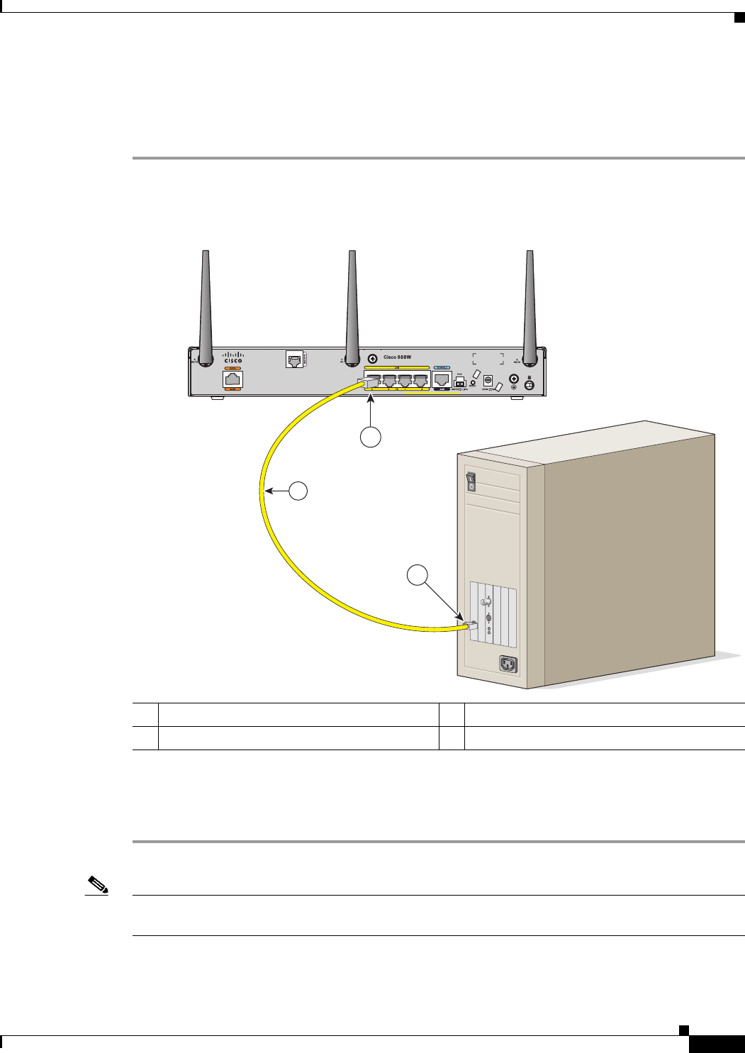
Step 1 Connect one end of the yellow Ethernet cable to an Ethernet switch port on the router. Figure 3-1 shows
a Cisco 888W router connected to a PC.
Figure 3-1 Connecting a Server, PC, or Workstation
Step 2 Connect the other end of the cable to the RJ-45 port on the network interface card (NIC) that is installed
in the PC, server, or workstation.
Step 3 (Optional) Connect additional servers, PCs, or workstations to the other Ethernet switch ports.
Note Use the Cisco Configuration Express to configure the Internet connection settings. See
Cisco Configuration Professional Quick Start Guide for more information.
1Yellow Ethernet cable supplied with the router 3RJ-45 port on the network interface card
2Ethernet switch port on the router
3
2
231989
1
3-6
Cisco 860 Series, Cisco 880 Series, and Cisco 890 Series Integrated Services Routers Hardware Installation Guide
OL-16215-10
Chapter 3 Connecting the Router
Connecting a Phone
Connecting a Phone
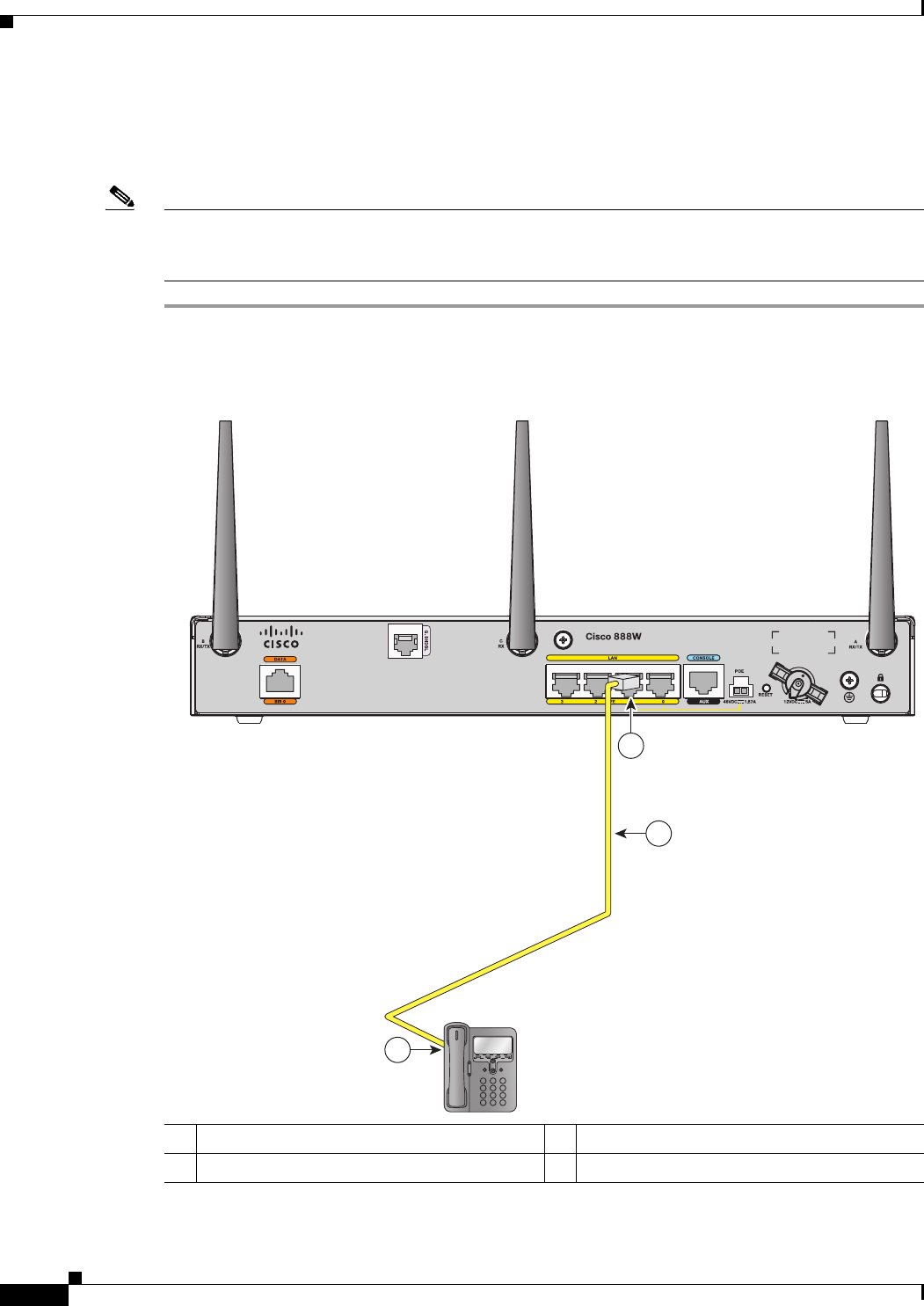
To connect an 802.3af-compliant phone to an Ethernet switch port, follow these steps:
Note A power source must be provided for the phone to function. This can be done in two ways: the phone
can be powered via the PoE function using the PoE enabled Ethernet ports, or by using an external AC
power source connected to the phone.
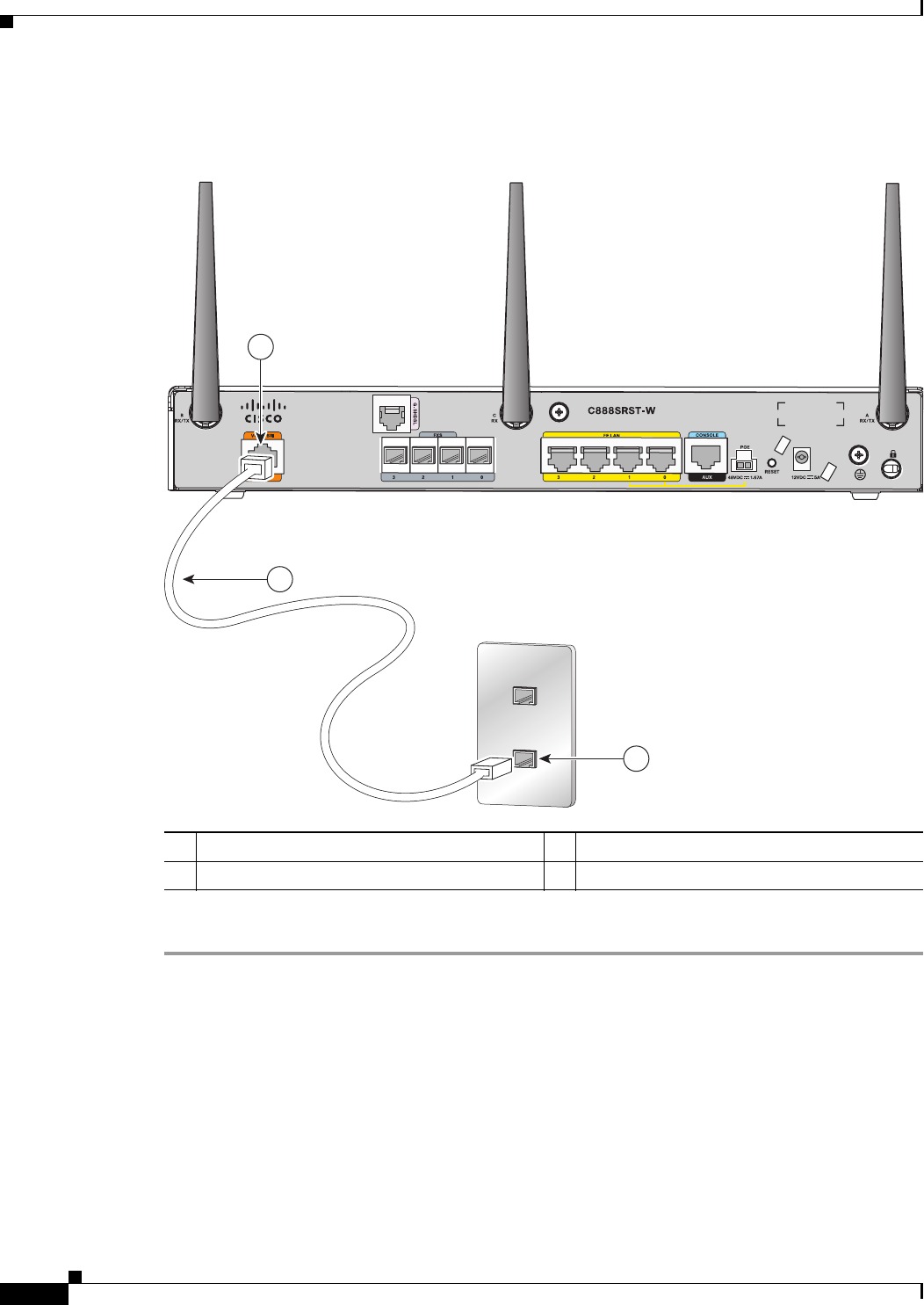
Step 1 Connect one end of the yellow Ethernet cable to Ethernet switch port 0 or port 1 on the router. Figure 3-2
shows a Cisco 888W router connected to a phone.
Figure 3-2 Connecting a Phone
1Yellow Ethernet cable 3RJ-45 port on a phone
2Ethernet switch port 1 on the router
3
2
270551
1
12
ABC
3
DEF
45
JKLGHI
6
MNO
78
TUVPQRS
9
WXYZ
*0
OPER
#
3-7
Cisco 860 Series, Cisco 880 Series, and Cisco 890 Series Integrated Services Routers Hardware Installation Guide
OL-16215-10
Chapter 3 Connecting the Router
Connecting an External Ethernet Switch
Step 2 Connect the other end of the cable to the RJ-45 port on the phone.
Connecting an External Ethernet Switch
If more than four PCs in an office must be connected to each other, you can add Ethernet connections to
the router by connecting an external Ethernet switch to the Ethernet switch on the router.
To connect an external Ethernet switch to an Ethernet switch port on the router, complete the following
steps:
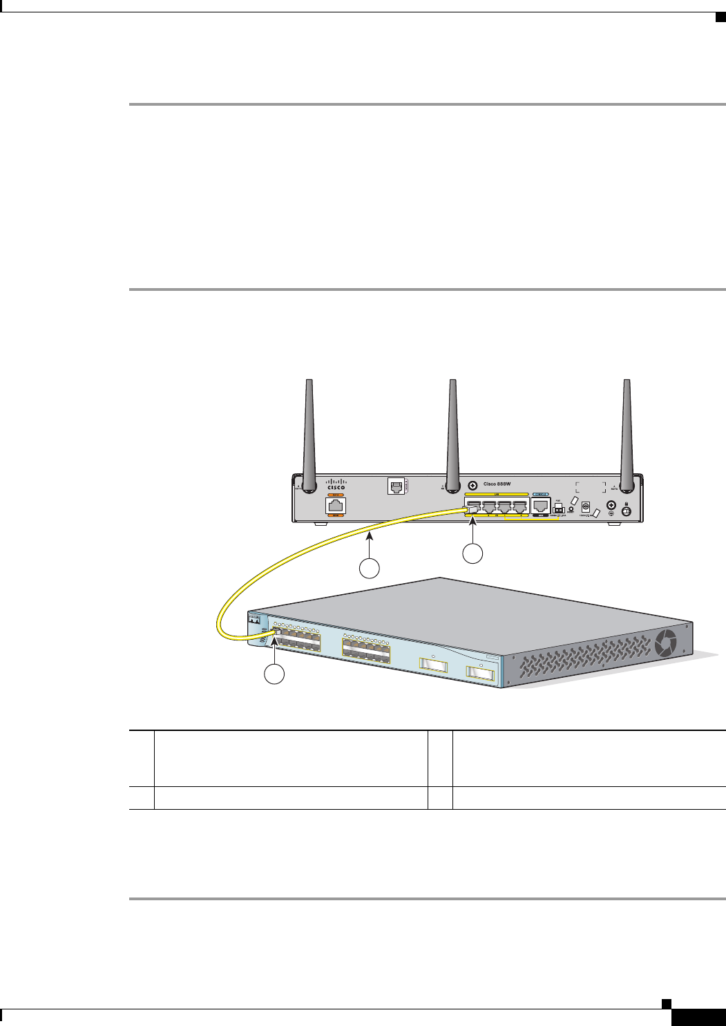
Step 1 Connect one end of the yellow Ethernet cable to an Ethernet switch port on the router. Figure 3-3 shows
a Cisco 888W router connected to an Ethernet switch.
Figure 3-3 Connecting to an Ethernet Switch
Step 2 Connect the other end of the cable to the available port on the Ethernet switch to add additional Ethernet
connections.
Step 3 Turn on the Ethernet switch.
1 Ethernet switch port on the router 3Yellow CAT5 Ethernet cable,
RJ-45–to–RJ-45, connecting to an external
Ethernet switch port
2Available port on the external Ethernet switch
MODE
Catalyst 3500
SERIES
XL
INLINE POWER
SYSTEM
1X
2X
15X
16X
RPS
STATUS
UTIL
DUPLX
SPEED
12345678910 11 12
1
1X
2X
15X
16X
12345678910 11 12
2
231986
1
3
2
3-8
Cisco 860 Series, Cisco 880 Series, and Cisco 890 Series Integrated Services Routers Hardware Installation Guide
OL-16215-10
Chapter 3 Connecting the Router
Connecting the V.92 modem Port
Connecting the V.92 modem Port
Warning
Hazardous network voltages are present in WAN ports regardless of whether power to the unit is OFF
or ON. To avoid electric shock, use caution when working near WAN ports. When detaching cables,
detach the end away from the unit first.
Statement 1026
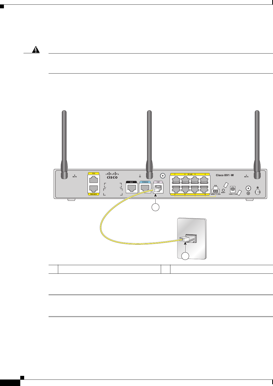
For dialup connection to your service provider network through the V.92 port, follow the steps given
after Figure 3-4, which show this connection.
Figure 3-4 Connecting to Your Service Provider Through the V.92 port
To connect the router to your service provide network through the V.92 port, follow these steps:
Step 1 Connect one end of the straight-through R-J11 cable to the V.92 port.
Step 2 Connect the other end of the straight through R-J11 cable to an RJ-11 telephone wall outlet.
1V.92 port on the router 2Telephone wall outlet
272387
1
2
3-9
Cisco 860 Series, Cisco 880 Series, and Cisco 890 Series Integrated Services Routers Hardware Installation Guide
OL-16215-10
Chapter 3 Connecting the Router
Connecting a Terminal or PC to the Console Port
Connecting a Terminal or PC to the Console Port
Connect a terminal or PC to the Console Auxiliary (Aux) port either to configure the software by using
the CLI or to troubleshoot problems with the router.
To connect a terminal or PC to the console port on the router and access the CLI, follow these steps:
Step 1 Connect the RJ-45 end of a DB-9–to–RJ-45 serial cable to the RJ-45 Console Aux port on the router.
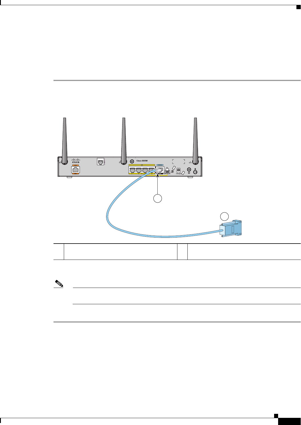
Figure 3-5 shows the RJ-45 end of the serial cable connected to the Console Aux port on the router.
Figure 3-5 Connecting a Terminal or PC to the Console Port
Step 2 Connect the DB-9 end of the DB-9–to–RJ-45 serial cable to the to the COM port on your laptop or PC.
Note Some laptops and PCs do not come with DB-9 serial port connectors and may require a
USB-to-serial port adapter.
Step 3 To communicate with the router, start a terminal emulator application.
1 RJ-45 connector to the Console Aux port on
the router
2DB-9 connector
2
1
231990
3-10
Cisco 860 Series, Cisco 880 Series, and Cisco 890 Series Integrated Services Routers Hardware Installation Guide
OL-16215-10
Chapter 3 Connecting the Router
Connecting a Modem to the Auxiliary Port
Terminal Emulator Settings
Use the following settings for the terminal emulator connection:
• 9600 baud
• 8 data bits, no parity
• 1 stop bit
• No flow control
When the terminal emulator establishes communications, the router prompt is displayed.
For more information on terminal emulation settings, see Applying Correct Terminal Emulator Settings
for Console Connections.
Connecting a Modem to the Auxiliary Port
To connect a modem to the router, follow these steps:
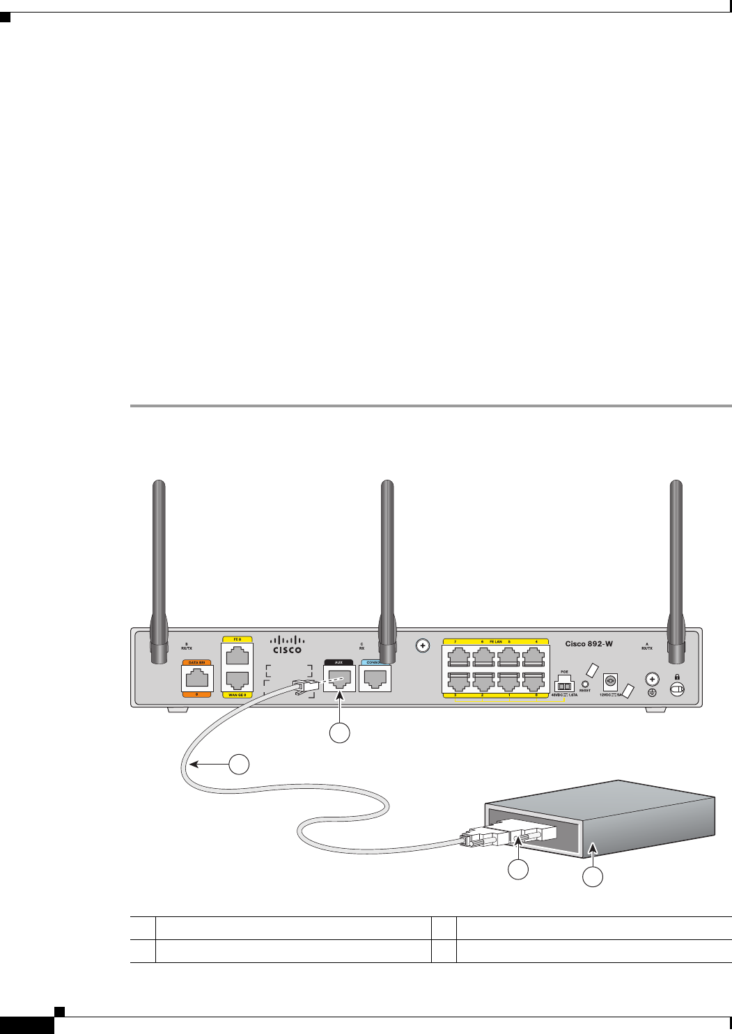
Step 1 Connect the RJ-45 end of the adapter cable to the Aux port on the router as shown in Figure 3-6.
Figure 3-6 Connecting a Modem to the Aux Port
1Aux port (RJ-45) 3DB-9 to DB-25 modem adapter (if required)
2Light blue console cable 4Modem
272386
1
2
34
3-11
Cisco 860 Series, Cisco 880 Series, and Cisco 890 Series Integrated Services Routers Hardware Installation Guide
OL-16215-10
Chapter 3 Connecting the Router
Connecting the 3G Card
Step 2 Connect the DB-9 end of the console cable to the DB-9 end of the modem adapter.
Step 3 Connect the DB-25 end of the modem adapter to the modem.
Step 4 Make sure that your modem and the router auxiliary port are configured for the same transmission speed
(up to 115200 bits per second [b/s] is supported) and support mode control with data carrier detect
(DCD) and data terminal ready (DTR).
Connecting the 3G Card
Note For information on embedded multiband, multiservice WAN modems, see Configuring Cisco EHWIC
and 880G for 3G (EV-DO Rev A) and Configuring Cisco EHWIC and 880G for 3.7G (HSPA+)/3.5G
(HSPA).
Note The Cisco 880G router does not support online insertion and removal (OIR) of the third-generation (3G)
card. You must enter the shutdown command on the cellular interface before you remove the 3G card
from the router.
To connect and secure the 3G card, follow these steps:
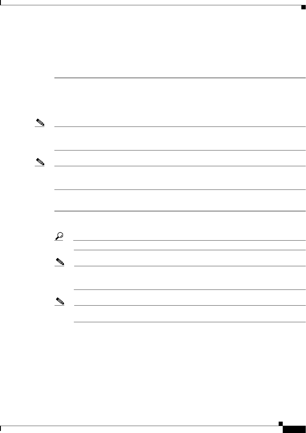
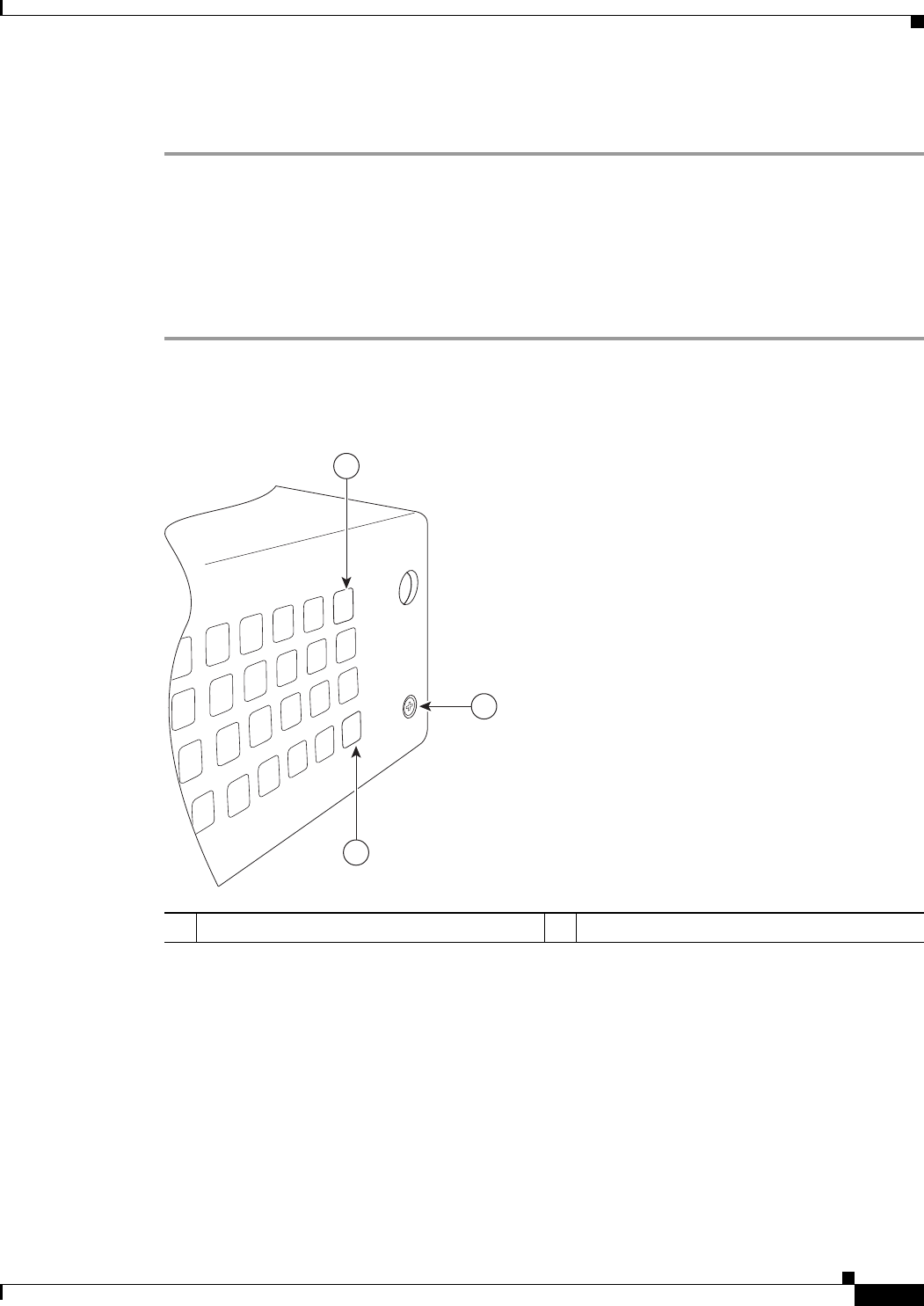
Step 1 Align the 3G card to the 3G express card slot, as shown in Figure 3-7. Keep the card parallel to the
surface and firmly push the card into the slot.
Tip Holding the 3G card on the flat metal surface makes it easier to align and insert the 3G card.
Note When inserting the card into the 3G express card slot, you may hear a metal-on-metal sound as
the 3G card rubs against the internal metal cage. The 3G card is designed to fit tightly into the
3G express card slot. Firm pressure may be required to insert the card.
Note Global System for Mobile Communications (GSM) customers need to insert a SIM card,
provided by their network carrier, into the 3G card.
3-12
Cisco 860 Series, Cisco 880 Series, and Cisco 890 Series Integrated Services Routers Hardware Installation Guide
OL-16215-10
Chapter 3 Connecting the Router
Connecting the 3G Card
Figure 3-7 Inserting the 3G Card
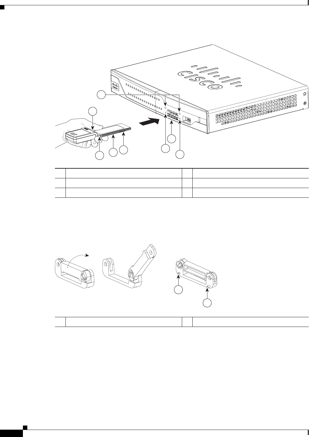
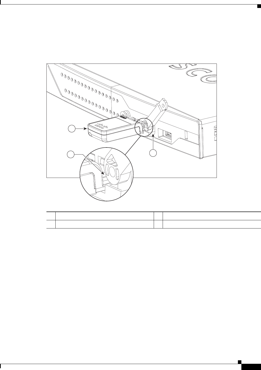
Step 2 Open the top of the anti-theft locking bracket, as shown in Figure 3-8.
Figure 3-8 Opening the Anti-theft Locking Bracket
13G card with the Cisco logo facing up 4Screw holes for locking bracket
23G express card slot 5Pin holes for aligning the locking bracket
3Notches on the 3G card 6SIM slot (in HSPA1 cards only)
1. HSPA = High-Speed Packet Access.
271473
16
2
5
4
5
3
3
1Pins on the locking bracket for alignment
271474
Front View Back View
1
1
3-13
Cisco 860 Series, Cisco 880 Series, and Cisco 890 Series Integrated Services Routers Hardware Installation Guide
OL-16215-10
Chapter 3 Connecting the Router
Connecting the 3G Card
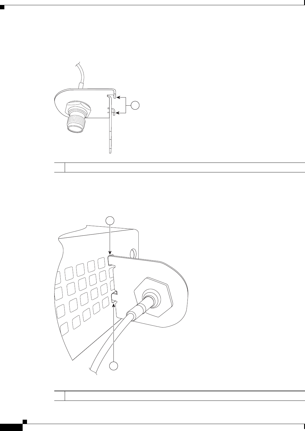
Step 3 Slide the opened locking bracket under the 3G card. The locking bracket should align with the notches
on either side of the 3G card, as shown in Figure 3-9, and the pins on the locking bracket should be
inserted into the corresponding holes in the router.
Figure 3-9 Installing the Locking Bracket
13G card 3Notch on the 3G card
2Locking bracket
1
2
3
271726
3-14
Cisco 860 Series, Cisco 880 Series, and Cisco 890 Series Integrated Services Routers Hardware Installation Guide
OL-16215-10
Chapter 3 Connecting the Router
Connecting the 3G Card
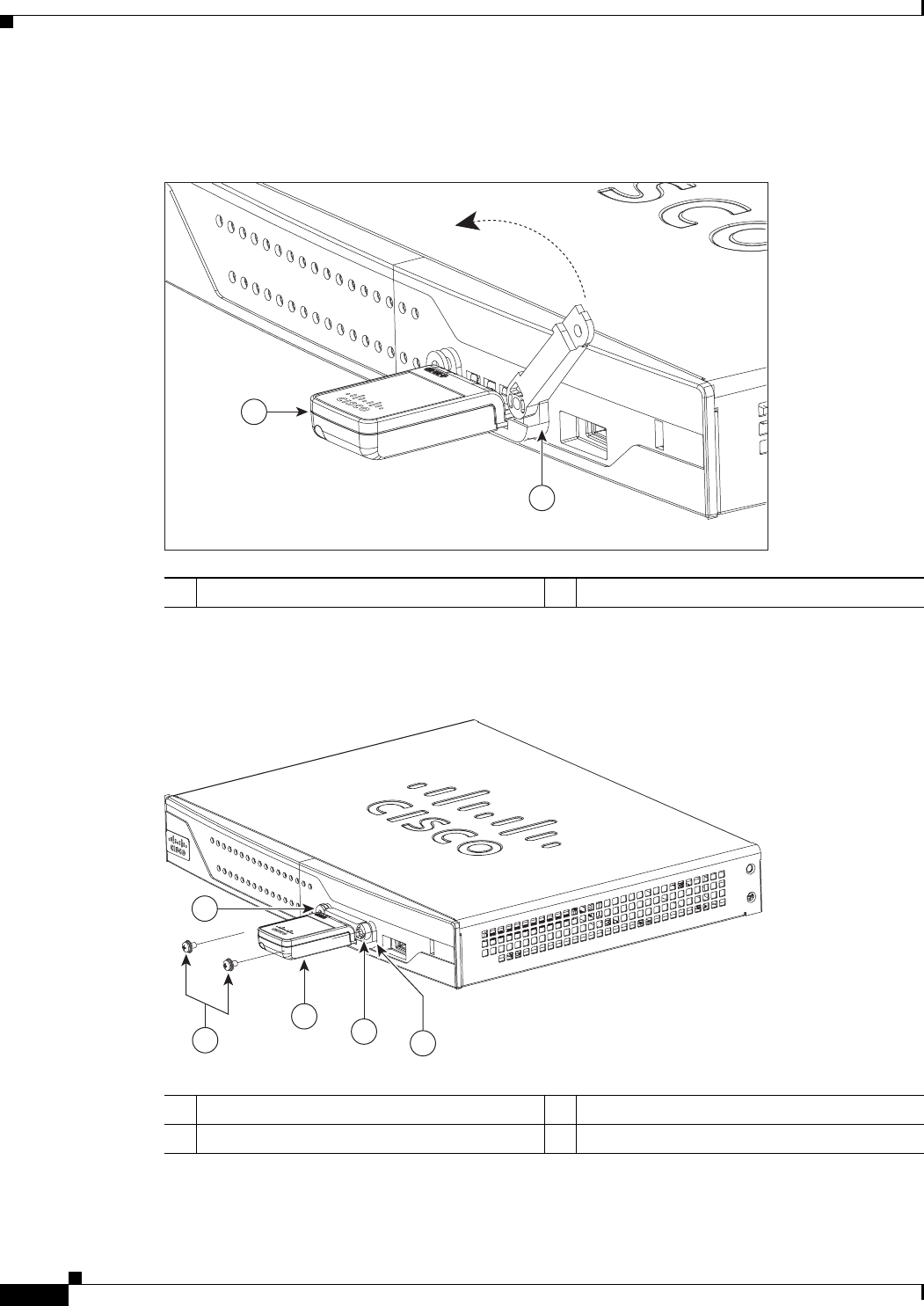
Step 4 Close the locking bracket, as shown in Figure 3-10.
Figure 3-10 Closing the Locking Bracket
Step 5 Insert the screws, as shown in Figure 3-11, and tighten with a number 2 Phillips screwdriver.
Figure 3-11 Inserting the Screws
Step 6 To connect the antenna to the 3G card, insert the antenna connector into the antenna connector receptacle
on the 3G card.
13G card 2Locking bracket
1
2
271580
13G card 3Screws
2Locking bracket 4Screw holes on the locking bracket
271476
342
1
4
3-15
Cisco 860 Series, Cisco 880 Series, and Cisco 890 Series Integrated Services Routers Hardware Installation Guide
OL-16215-10
Chapter 3 Connecting the Router
Connecting the 3G Card
Note The antenna connector receptacle may be located on the left, right, or front of the 3G card, depending
on your card.
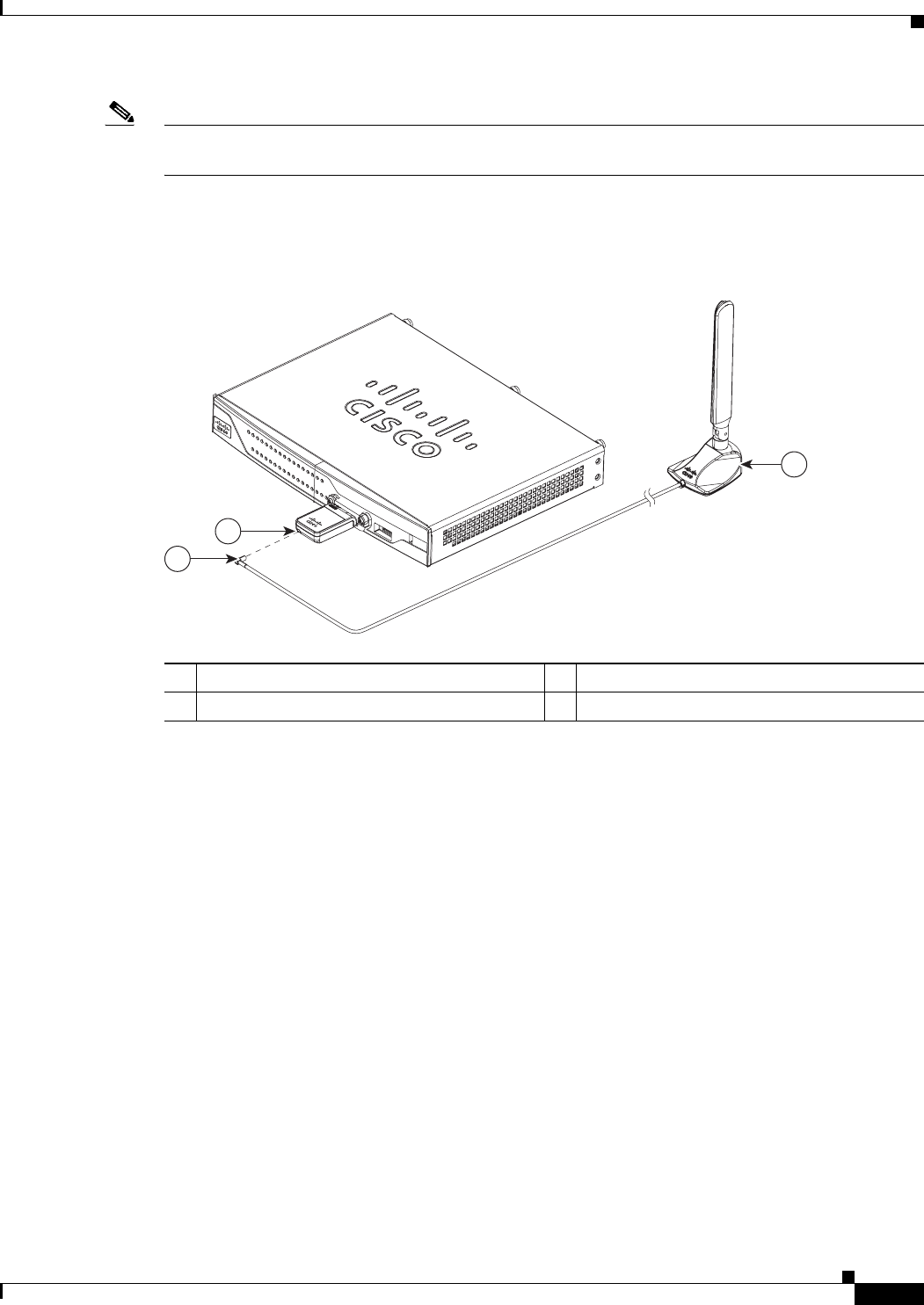
Figure 3-12 shows the antenna connected to the 3G card with an SSMB type plug, and Figure 3-13 shows
the antenna with the SMK-TS-9 connector.
Figure 3-12 Antenna connected to the 3G Card with SSMB connector
1Antenna on a cradle 3Antenna connector receptacle1
1. The antenna connector receptacle is located on either the left, right or front of the card for different SKUs. Please locate the
receptacle of your card before plugging in the cable.
2Antenna SSMB connector
272653
1
2
3
3-16
Cisco 860 Series, Cisco 880 Series, and Cisco 890 Series Integrated Services Routers Hardware Installation Guide
OL-16215-10
Chapter 3 Connecting the Router
Connecting the 3G Card
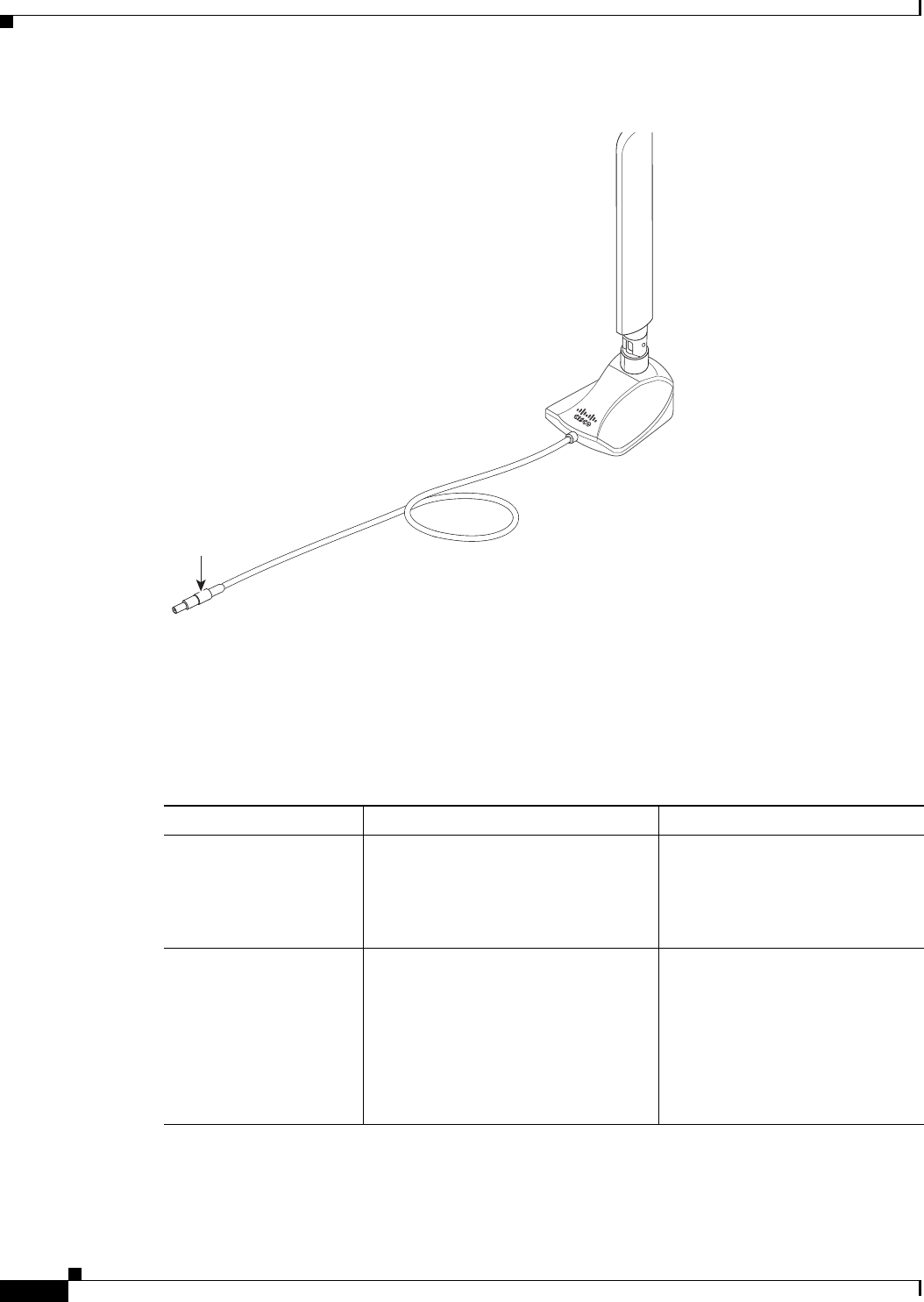
Figure 3-13 Antenna with the SMK-TS- 9 Connector
If you are using an extension cable, you must attach the 3G adapter for extended cable antenna to the
body of the router. Depending on the SKU ordered, the adapters come with different connectors.
Table 3-1 lists the different adapters and SKUs supported by each adapter. For instructions on how to
install the adapter, see the “Installing the 3G Adapter for Extended Cable/Antenna” section on
page 3-17. Otherwise, follow Step 7.
Step 7 Clean the flat surface to which you will affix the antenna.
279085
Original
antenna assembly
SMK-TS-9
connector Cable
Ta b l e 3-1 3G Adapters and Supported SKUs
3G Adapter SKU Description SKUs Supported
3G-ACC-SMKTS9-TNC 3G adapter for extended cable/antenna
with an SMK-TS-9 to TNC connector.
Use this with the pentaband dipole
indoor antenna
(3G-ANTM-SMKTS9).
PCEX-3G-HSPA-R6,
CISCO881G-G-K9
3G-ACC-SSMB-TNC 3G adapter for extended cable/antenna
with an SSMB to TNC connector. Use
this with the pentaband dipole indoor
antenna shipped with your product.
PCEX-3G-HSPA,
PCEX-3G-HSPA-A,
PCEX-3G-CDMA-S,
PCEX-3G-CDMA-V,
PCEX-3G-CDMA-B,
CISCO881G-A-K9,
CISCO881G-S-K9,
CISCO881G-V-K9
3-17
Cisco 860 Series, Cisco 880 Series, and Cisco 890 Series Integrated Services Routers Hardware Installation Guide
OL-16215-10
Chapter 3 Connecting the Router
Installing the 3G Adapter for Extended Cable/Antenna
Step 8 Remove the protective tape from the adhesive on the bottom of the antenna cradle, then firmly press the
cradle to the flat surface.
Installing the 3G Adapter for Extended Cable/Antenna
For better signal and reception, if you are using the Cisco 3G Adapter for Extended Cable/Antenna,
3G-ACC-SMKTS9-TNC, follow these steps to install it:
Step 1 Locate and remove the Phillips screw on the left side of the router as shown in Figure 3-14. Keep the
screw aside for Step 4.
Figure 3-14 Locating the Phillips Screw
1Phillips screw on the left side of router 2Air vent holes to be aligned with adapter
279124
2
2
1
3-18
Cisco 860 Series, Cisco 880 Series, and Cisco 890 Series Integrated Services Routers Hardware Installation Guide
OL-16215-10
Chapter 3 Connecting the Router
Installing the 3G Adapter for Extended Cable/Antenna
Step 2 Locate the hooks on the adapter as shown in Figure 3-15.
Figure 3-15 Locating the Hooks on the Adapter
Step 3 Align and insert the hooks of the adapter into the air vent holes on the left side router body as shown in
Figure 3-16.
Figure 3-16 Inserting the Hooks
279122
1
1Hooks on the adapter
279123
1
1
1Hooks aligned and inserted into the router.

3-19
Cisco 860 Series, Cisco 880 Series, and Cisco 890 Series Integrated Services Routers Hardware Installation Guide
OL-16215-10
Chapter 3 Connecting the Router
Installing the 3G Adapter for Extended Cable/Antenna
Step 4 Align the circular adapter hole with the hole on the router chassis from where you removed the screw in
Step 1 and use the screw to attach the adapter to the router as shown in Figure 3-17.
Figure 3-17 Attaching the Adapter
279091
3-20
Cisco 860 Series, Cisco 880 Series, and Cisco 890 Series Integrated Services Routers Hardware Installation Guide
OL-16215-10
Chapter 3 Connecting the Router
Installing the 3G Adapter for Extended Cable/Antenna
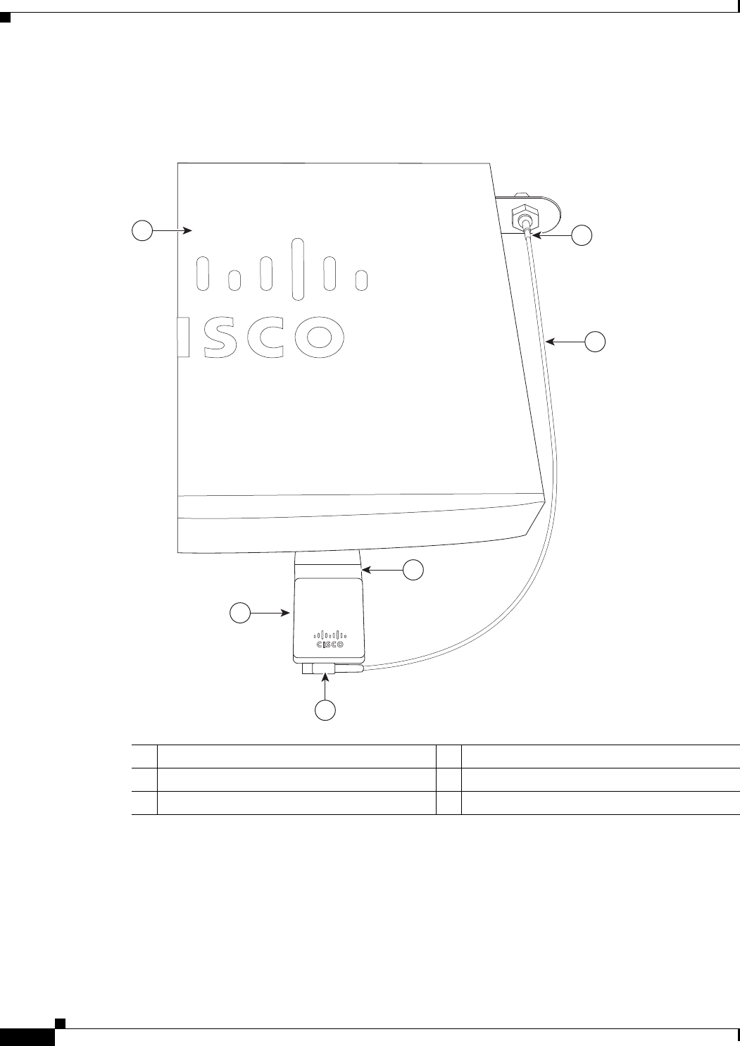
Step 5 Connect the extension cable to the 3G card, as described in the “Connecting the 3G Card” section on
page 3-11. The complete assembly is shown in Figure 3-18.
Figure 3-18 Adapter Connected to 3G Card and Router Chassis
Now the adapter is ready for use with the extension cable. Table 3-2 lists the loss information for the
ultra-low-loss (ULL) LMR 400 cables available with the adpater for the 3G fixed platforms.
1Router chassis 4SSMB or SMK-TS-9 connector
23G adapter for extended cable/antenna 53G card inserted into the router
3Cable 63G card
279089
3
2
1
6
5
4
3-21
Cisco 860 Series, Cisco 880 Series, and Cisco 890 Series Integrated Services Routers Hardware Installation Guide
OL-16215-10
Chapter 3 Connecting the Router
Connecting a Data BRI Port
Note Antenna orientation can increase or decrease signal reception due to polarization. Typically, an SP’s
transmitting antenna on the BTS is a vertically polarized omnidirectional antenna, which means the
electromagnetic waves are transmitted from it in a vertical plane. Hence, the receiving antenna needs to
be vertically oriented too in order to receive the best signal. As the angle of the antenna orientation is
changed from vertical to horizontal, only an angular component of the signal is picked up by the antenna.
Therefore, if the antenna orientation is horizontal, the antenna picks up the least signal. The signal is
received by the antenna as a result of it bouncing off of reflective surfaces. Hence, depending on where
the antenna is placed, it may receive different signal strengths. However, the recommended position is
vertical.
For additional information on all the available cables and antennas available for 3G, go to:
http://www.cisco.com/en/US/docs/routers/access/1800/1861/software/feature/guide/mrwlsgsm.html#w
p1262730
Connecting a Data BRI Port
You can connect the Data BRI port to the ISDN service provider as a backup link to the WAN port in
case the primary xDSL (general term referring to various forms of DSL, including global industry
standard symmetrical high-speed DSL [G.SHDSL]) WAN service fails. The Data BRI connection is not
available on the third-generation (3G) models.
The cabling requirements for the ISDN S/T connection are as follows:
• You must provide two unshielded Category 5 cables. The first cable connects the NT1 box to the
splitter, and the second cable connects the splitter to the wall jack.
• There are RJ-45 connectors at both ends of the default orange ISDN S/T cable. However, an
RJ-45–to–RJ-11 ISDN S/T cable is available upon request if the wall jack at the site requires an
RJ-11 connector. Contact your router reseller for the appropriate cable.
Caution Both LAN and WAN ports use RJ-45 connectors. Use caution when connecting cables to these
connectors. To avoid damage to the router, do not connect telephone-network voltage (TNV) circuits
(such as ISDN or DSL circuits) to safety extra-low voltage (SELV) circuits (such as LAN circuits).
Although the following procedure shows a Cisco 888W data router, this procedure applies to all
Cisco 880 series router with a Data BRI port.
Ta b l e 3-2 Cisco Adapter Cables for Use with 3G Fixed Routers
Cisco Product Number
Antenna Adapter
Length Insertion Loss Frequency (MHz)
3G-ACC-SSMB-TNC 14.5 inches 0.66 dB 2100
3G-ACC-TS9-TNC 13.5 inches 0.62 dB 2100
3-22
Cisco 860 Series, Cisco 880 Series, and Cisco 890 Series Integrated Services Routers Hardware Installation Guide
OL-16215-10
Chapter 3 Connecting the Router
Connecting a Data BRI Port
To connect the Data BRI port to the ISDN service provider, follow these steps:
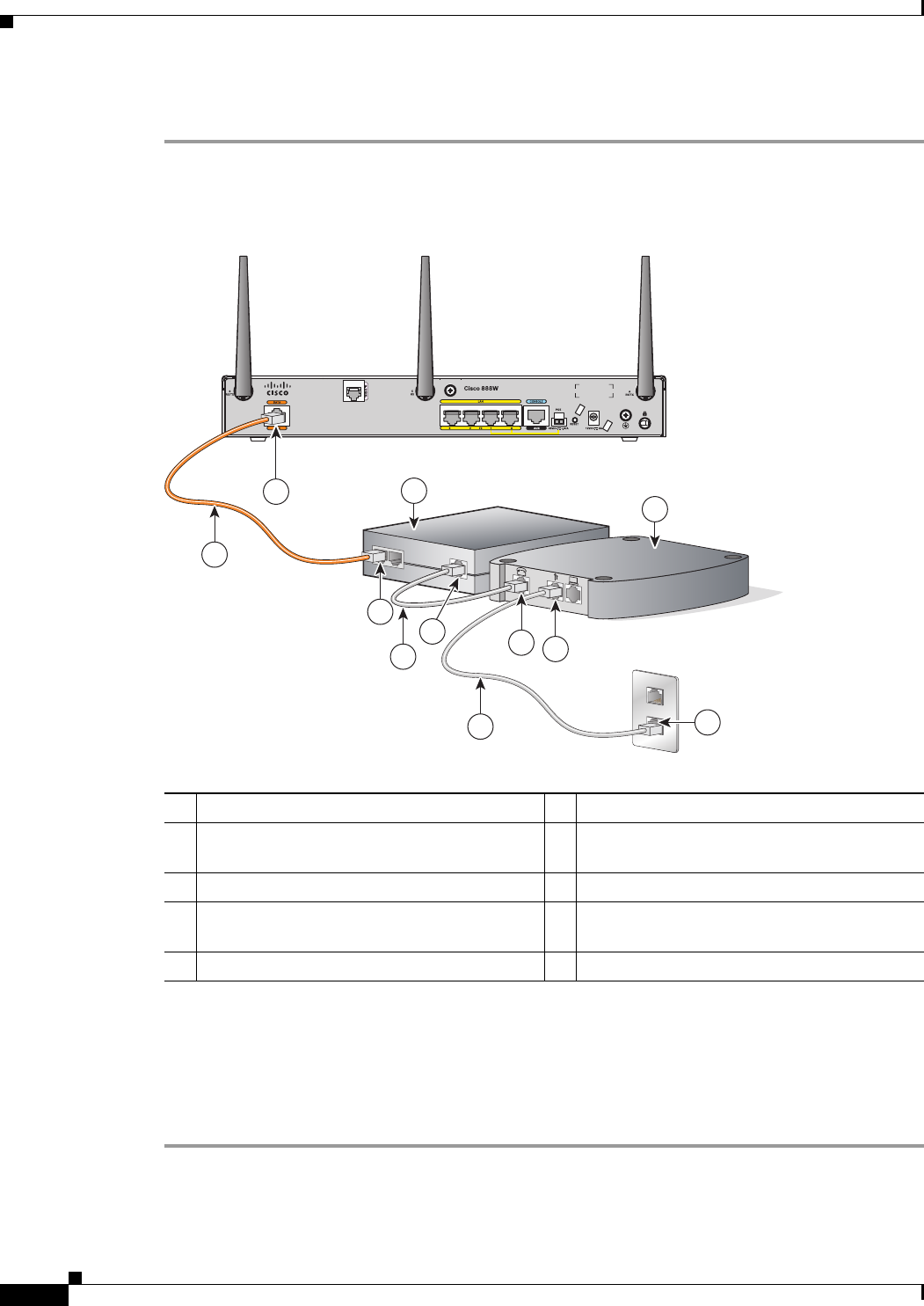
Step 1 Connect one end of the orange ISDN S/T cable to the Data BRI port on the router. Figure 3-19 shows a
Data BRI connection.
Figure 3-19 Connecting the Data BRI Port to the ISDN Line
Step 2 Connect the other end of the orange ISDN S/T cable to the S/T port on the NT1 box.
Step 3 Connect the first unshielded CAT 5 cable from the U-port on the NT1 box to the telephone line port on
the splitter.
Step 4 Connect the second unshielded Category 5 cable from the telecommunication service port on the splitter
to the wall jack to allow a link to the network service provider.
1Data BRI port on the router 6U-port on the NT1 box
2ISDN S/T cable 7xDSL splitter (provided by the xDSL service
provider)
3Network termination 1 (NT1) box 8Telephone line port on the splitter
4S/T port on the NT1 box 9Telecommunication service port on the
splitter
5Unshielded CAT 5 cable 10 Wall jack
231991
3
1
4
2
10
69
8
7
5
5
3-23
Cisco 860 Series, Cisco 880 Series, and Cisco 890 Series Integrated Services Routers Hardware Installation Guide
OL-16215-10
Chapter 3 Connecting the Router
Connecting an FE Line to an FE WAN Port
Connecting an FE Line to an FE WAN Port
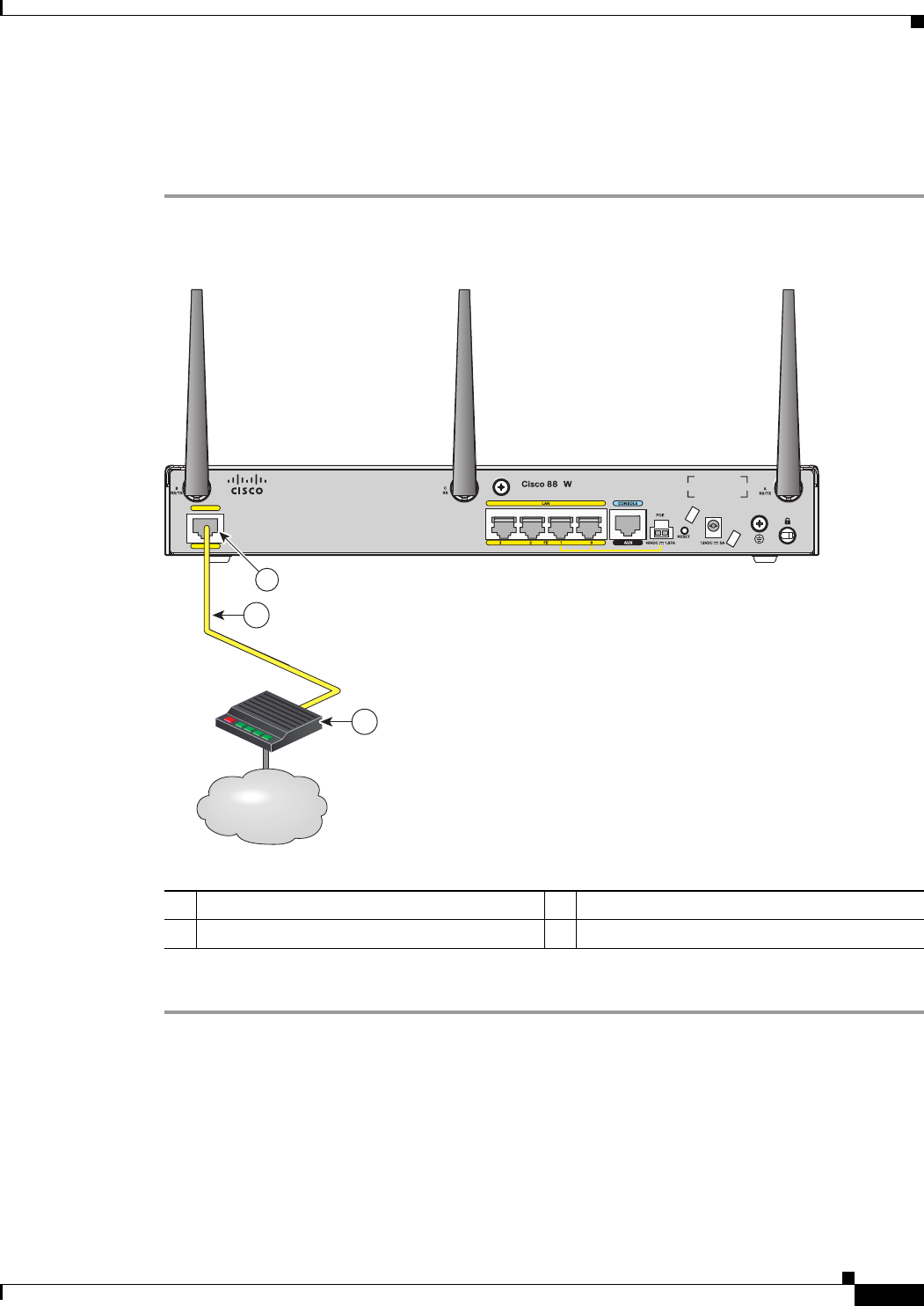
To connect the Fast Ethernet (FE) WAN port on the router, follow these steps:
Step 1 Connect one end of the yellow cable to the FE WAN port as shown in Figure 3-20.
Figure 3-20 Connecting the FE WAN Port
Step 2 Connect the other end of cable to an available port on the modem.
1FE WAN port 3Modem connected to the Internet
2CAT 5 cable
WAN
FE 4
1
InternetInternetInternet
2
3
231992
1
3-24
Cisco 860 Series, Cisco 880 Series, and Cisco 890 Series Integrated Services Routers Hardware Installation Guide
OL-16215-10
Chapter 3 Connecting the Router
Connecting a GE Line to an GE WAN Port
Connecting a GE Line to an GE WAN Port
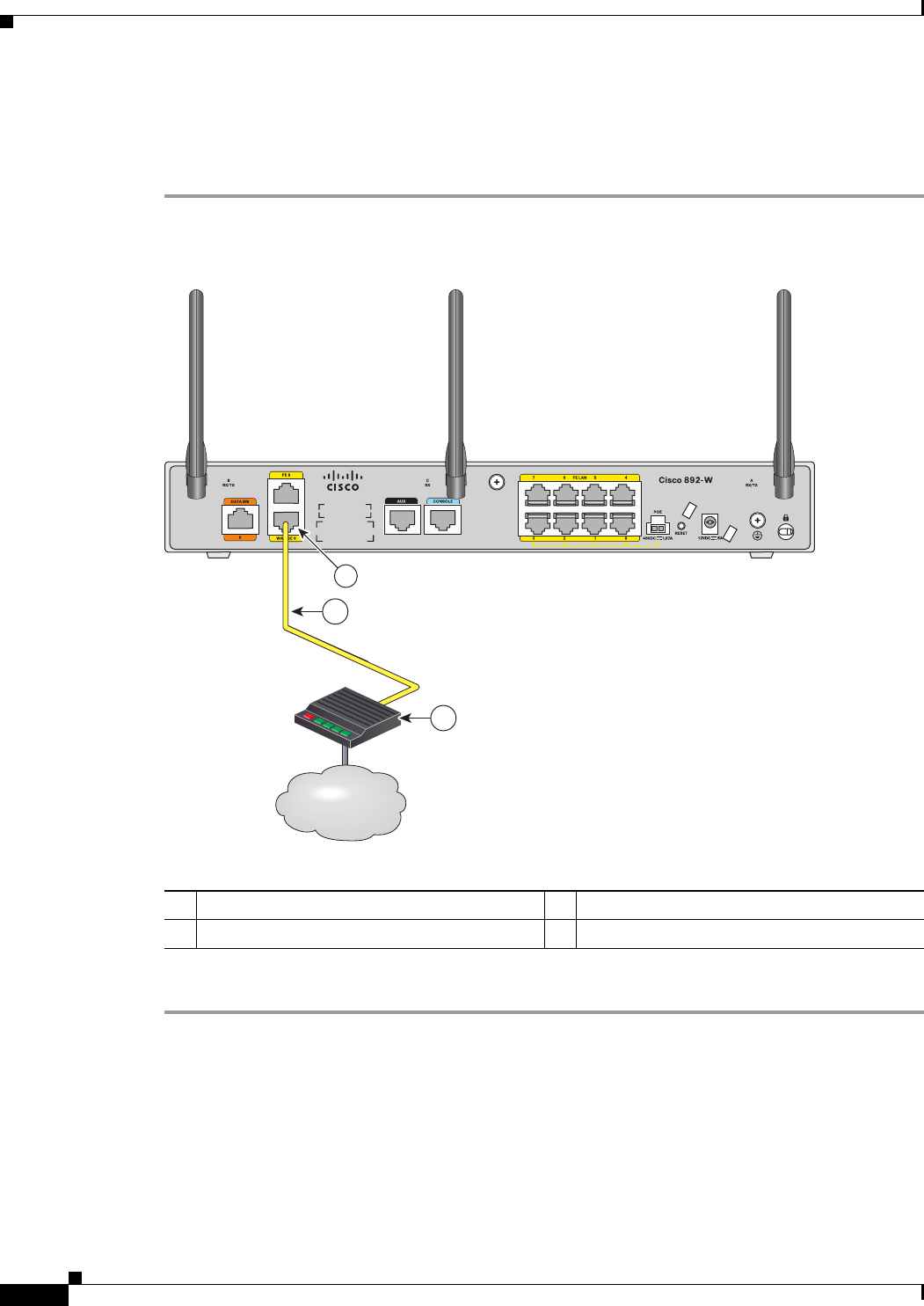
To connect the Gigabit Ethernet (GE) WAN port on the router, follow these steps:
Step 1 Connect one end of the yellow cable to the GE WAN port as shown in Figure 3-21.
Figure 3-21 Connecting the GE WAN Port
Step 2 Connect the other end of cable to an available port on the modem.
1GE WAN port 3Modem connected to the Internet
2CAT 5 cable
InternetInternetInternet
2
3
274493
1
3-25
Cisco 860 Series, Cisco 880 Series, and Cisco 890 Series Integrated Services Routers Hardware Installation Guide
OL-16215-10
Chapter 3 Connecting the Router
Connecting an xDSL Line
Connecting an xDSL Line
Warning
Hazardous network voltages are present in WAN ports regardless of whether power to the unit is OFF
or ON. To avoid electric shock, use caution when working near WAN ports. When detaching cables,
detach the end away from the unit first.
Statement 1026
Caution Cisco Systems DSL WAN Interfaces are tested for compliance with regulatory standards such as FCC
Part 68, ITU-T K.21, IEC 61000-4-5, and CSA/EN/IEC/UL 60950-1. These standards assume Primary
Protection devices protect the Customer Premise Equipment (CPE). These devices are normally
installed by the service provider, local exchange carrier or qualified service person and are located at the
telecom service provider entrance, network interface box, or demarcation point. See Figure 3-22 for the
likely location of the primary protection device. The primary protection device must be suitable for the
xDSL interface employed. Please contact your sales team or qualified service person for further
information and installation.
Caution To reduce the risk of fire, use only No. 26 AWG or larger (e.g., 24 AWG) UL Listed or CSA Certified
Telecommunication Line Cord.
Warning
Do not use this product near water; for example, near a bath tub, wash bowl, kitchen sink or laundry
tub, in a wet basement, or near a swimming pool.
Statement 1035
Warning
Avoid using a telephone (other than a cordless type) during an electrical storm. There may be a remote
risk of electric shock from lightning.
Statement 1038
Warning
To report a gas leak, do not use a telephone in the vicinity of the leak.
Statement 1039
Warning
There is the danger of explosion if the battery is replaced incorrectly. Replace the battery only with
the same or equivalent type recommended by the manufacturer. Dispose of used batteries according
to the manufacturer’s instructions.
Statement 1015
3-26
Cisco 860 Series, Cisco 880 Series, and Cisco 890 Series Integrated Services Routers Hardware Installation Guide
OL-16215-10
Chapter 3 Connecting the Router
Connecting an xDSL Line
Figure 3-22 Primary Protection Device Location
To connect the router to a global industry standard symmetrical high-speed DSL (G.SHDSL) line,
very-high-speed digital subscriber line 2 (VDSL2) port, or an ADSL2+ line, follow these steps:
Step 1 Connect one end of an RJ-11 (RJ-45 on 880 E models) cable to the port on the router. See Figure 3-23.
Figure 3-23 Connecting the xDSL Line
Step 2 Connect the other end of the cable to the DSL wall jack.
Router
Home or Business
Service Utilities Entrance
or Demarcation Point
Network Interface Box/
Network Interface Device/
Station Protector
Building Ground Rod connected to
Service entrance and Primary Protection
* Alternative Underground Service Entrance
Note: Primary Protection
may be located Outside
or Inside of Premise
Telecom Service
Overhead Service
Entrance
281392
1G.SHDSL port, VDSL2oPOTs port, or
ADSL2+ port
2DSL wall jack
232175
2
1

3-27
Cisco 860 Series, Cisco 880 Series, and Cisco 890 Series Integrated Services Routers Hardware Installation Guide
OL-16215-10
Chapter 3 Connecting the Router
Connecting Power over Ethernet
Caution The primary WAN port is designed for an RJ-45 connector only. Damage to the primary WAN port may
occur if a non-RJ-45 connector is inserted
Note The DSL line must be provisioned by your service provider and correctly configured so that the LED
shows the carrier detect (CD) status. On Cisco 860VAE routers, check the DSL Link LED.
Connecting Power over Ethernet
Warning
This unit might have more than one power supply connection. All connections must be removed to
de-energize the unit.
Statement 1028
Warning
This product must be connected to a power-over-ethernet (PoE) IEEE 802.3af compliant power source
or an IEC60950 compliant limited power source.
Statement 353
Figure 3-24 shows how to connect the 48-VDC Power over Ethernet (PoE) power adapter to your router.
The PoE adapter provides power to ports 0 and 1 of the 4-port 10/100 FE switch on the Cisco 880 series
routers and ports 0,1, 2, and 3 of the 8-port 10/100 FE switch on the Cisco 890 series routers.
Note The router must also be connected to an AC power outlet through a 12-VDC adapter. To connect the
router to an AC outlet, see the“Connecting the AC Adapter” section on page 3-28.
Note Be sure that the internal PoE is enabled for this connection procedure to work.
3-28
Cisco 860 Series, Cisco 880 Series, and Cisco 890 Series Integrated Services Routers Hardware Installation Guide
OL-16215-10
Chapter 3 Connecting the Router
Connecting the AC Adapter
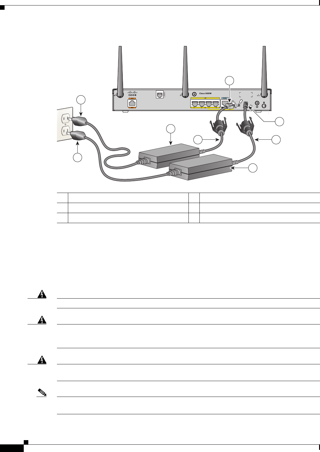
Figure 3-24 Connecting PoE for the Cisco 880 and the Cisco 890 Series Routers
The Cisco 880 series ISRs with embedded WLAN antennas require a single external power supply: a
30-W power supply for non-POE-enabled routers or a 60-W power supply for POE-enabled routers. For
the back panels of some of these routers, see Figure 1-17 and Figure 1-19.
Connecting the AC Adapter
Warning
The device is designed to work with TN power systems.
Statement 19
Warning
This product relies on the building’s installation for short-circuit (overcurrent) protection. Ensure that
the protective device is rated not greater than:
120 VAC, 20 A U.S. (240 VAC, 16 to 20 A international).
Statement 1005
Warning
This unit might have more than one power supply connection. All connections must be removed to
de-energize the unit.
Statement 1028
Note The Cisco 892FSP utilizes a single 4-pin power connector type. Figure 3-27 shows the pin number
assignment of the Cisco 892FSP Power Adapter Connector.
148-VDC PoE input jack 4AC plug
2Power cord 512-VDC input power-jack plug
3Power adapter—48 VDC 6Power adapter—12 VDC
231995
5
22
6
4
4
3
1
3-29
Cisco 860 Series, Cisco 880 Series, and Cisco 890 Series Integrated Services Routers Hardware Installation Guide
OL-16215-10
Chapter 3 Connecting the Router
Connecting the AC Adapter
To connect your Cisco 860 series, Cisco 880 series, or the Cisco 890FSP ISR to an AC power outlet,
follow these steps:
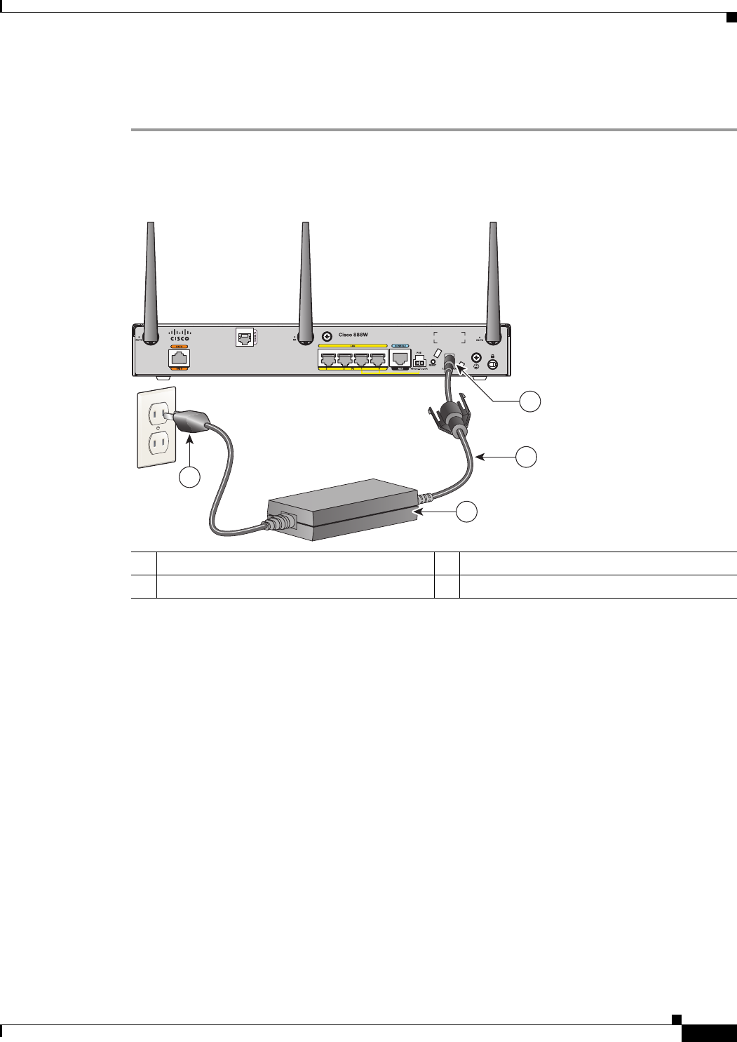
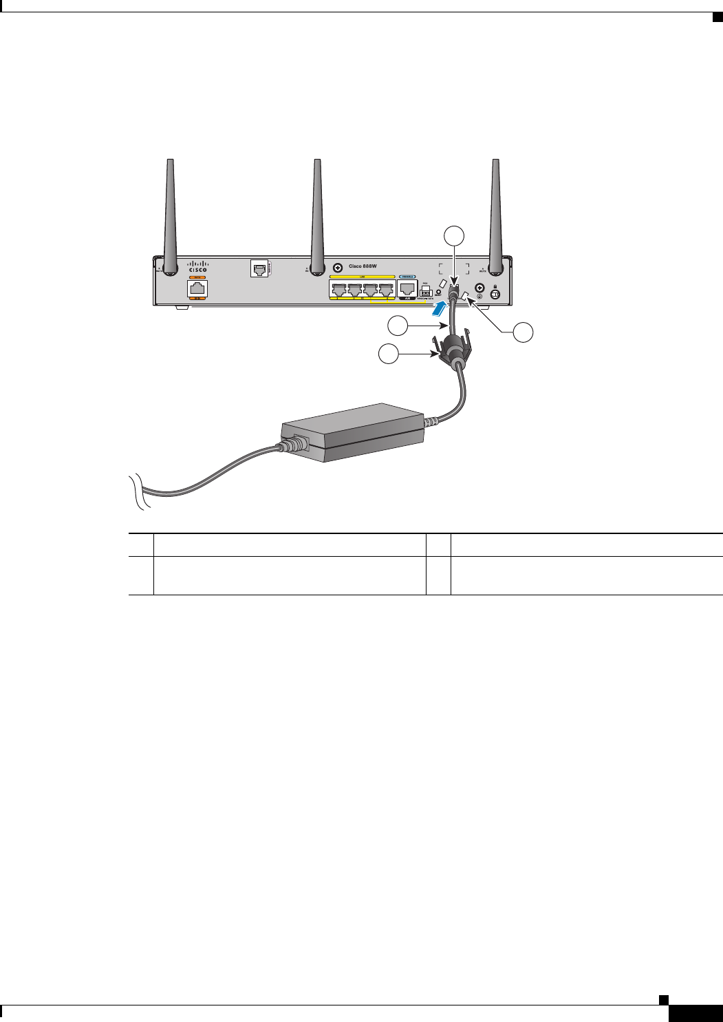
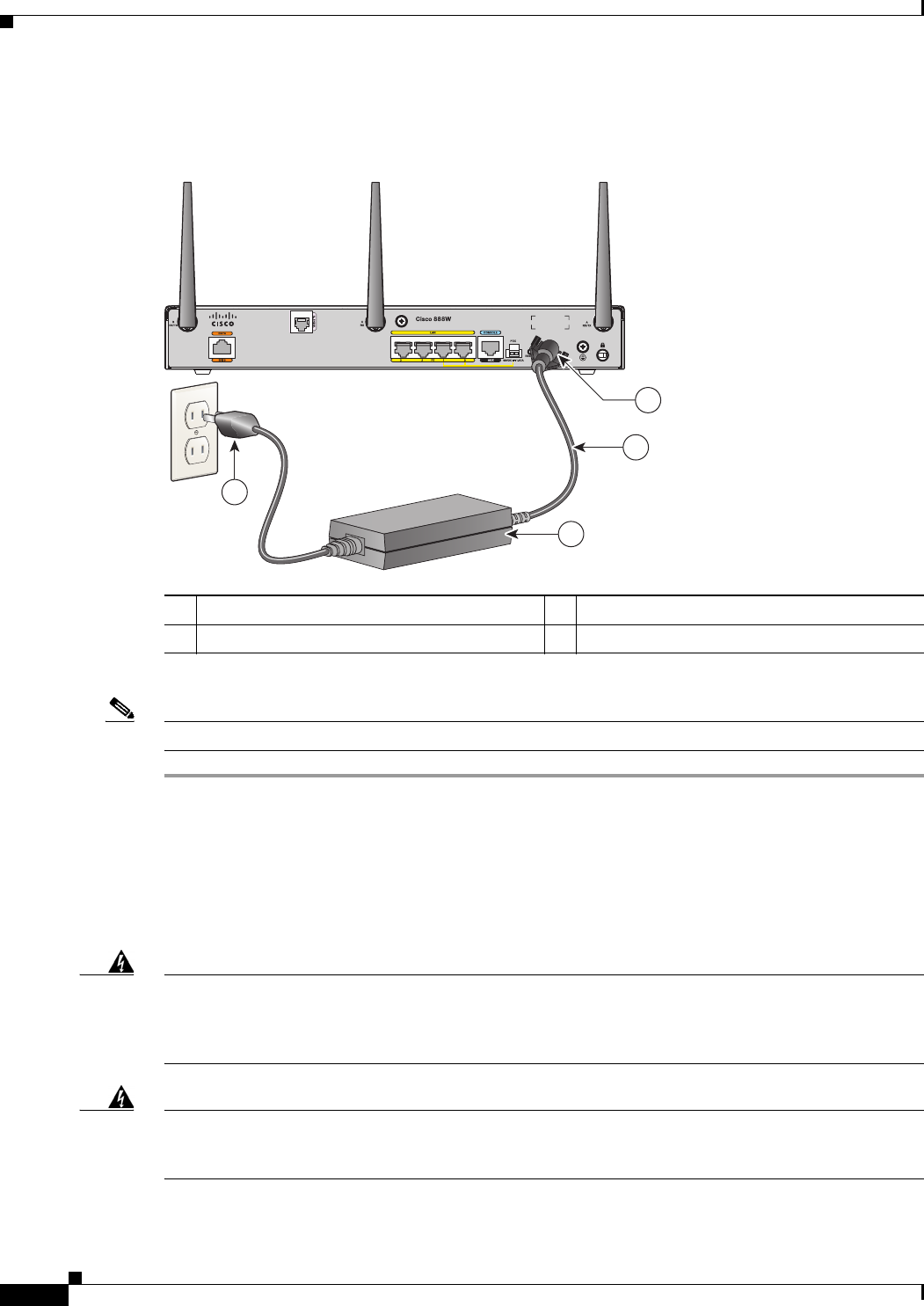
Step 1 Connect the router to an AC power outlet as shown in Figure 3-25.To connect the Cisco 892FSP router,
see Figure 3-26.
Figure 3-25 Connecting the AC Adapter
112-VDC plug 3Power adapter—12 VDC
2Power cord 4AC plug
231996
1
2
4
3
3-30
Cisco 860 Series, Cisco 880 Series, and Cisco 890 Series Integrated Services Routers Hardware Installation Guide
OL-16215-10
Chapter 3 Connecting the Router
Connecting the AC Adapter
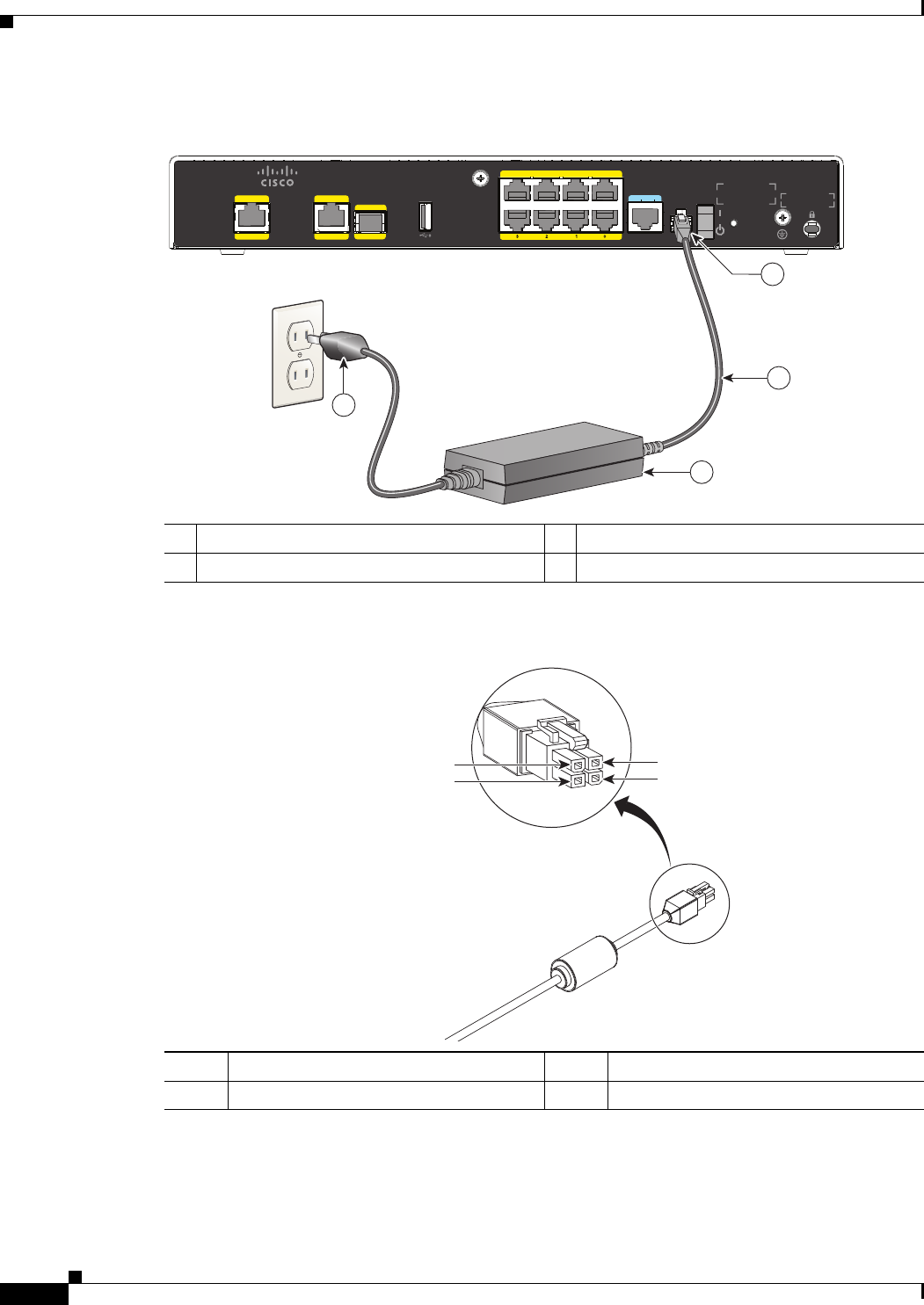
Figure 3-26 Connecting the AC Adapter for the Cisco 892FSP
Figure 3-27 Cisco 892FSP, 896VA, 897VA, and 898EA Power Adapter Connector Pin Assignment
7 6 GE LAN 5 4
9
GE WAN
8
GE WAN
SFP
812VD C 2.5A
CONSOLE
AUX RESET
Cisco 892FSP
343746
1
2
4
3
112-VDC plug 3Power adapter—12 VDC
2Power Adapter Cord 4AC Plug
284800
Pin 3
Pin 1 Pin 4
Pin 2
Pin 1 Ground Pin 3 +12 V
Pin 2 NC1Pin 4 NC
1. NC = No Connection.
3-31
Cisco 860 Series, Cisco 880 Series, and Cisco 890 Series Integrated Services Routers Hardware Installation Guide
OL-16215-10
Chapter 3 Connecting the Router
Connecting the AC Adapter
Step 2 To secure the power cord to the router, attach the power lock clip to the power cord, slide the clip to the
end of the DC plug, and secure the retaining clip into the router chassis. See Figure 3-28.
Figure 3-28 Securing the Power Cord
1Power lock clip 3DC plug
2Power cord 4Lock holes on either side of the power
connector
270659
4
2
1
3
3-32
Cisco 860 Series, Cisco 880 Series, and Cisco 890 Series Integrated Services Routers Hardware Installation Guide
OL-16215-10
Chapter 3 Connecting the Router
Connecting an FXS Line
Step 3 Snap the latches into the holes on either side of the power connector. See Figure 3-29.
Figure 3-29 Power Lock Clip Latched Into the Holes on Either Side of the Power Connector
Note Figure 3-26 shows how to connect the AC power outlet for the Cisco 892FSP.
Connecting an FXS Line
Use a standard straight-through RJ-11 modular telephone cable to connect a Foreign Exchange Service
(FXS) port to a telephone or fax machine.
Warning
This equipment contains a ring signal generator (ringer), which is a source of hazardous voltage. Do
not touch the RJ-11 (phone) port wires (conductors), the conductors of a cable connected to the RJ-11
port, or the associated circuit-board when the ringer is active. The ringer is activated by an incoming
call.
Statement 1042
Warning
Hazardous network voltages are present in WAN ports regardless of whether power to the unit is OFF
or ON. To avoid electric shock, use caution when working near WAN ports. When detaching cables,
detach the end away from the unit first.
Statement 1026
1Power lock clip 3Power adapter
2Power cord 4AC plug
270800
1
2
4
3
3-33
Cisco 860 Series, Cisco 880 Series, and Cisco 890 Series Integrated Services Routers Hardware Installation Guide
OL-16215-10
Chapter 3 Connecting the Router
Connecting an FXS Line
Warning
For connections outside the building where the equipment is installed, the following ports must be
connected through an approved network termination unit with integral circuit protection: FXS.
Statement 1044
To connect the FXS line, follow these steps:
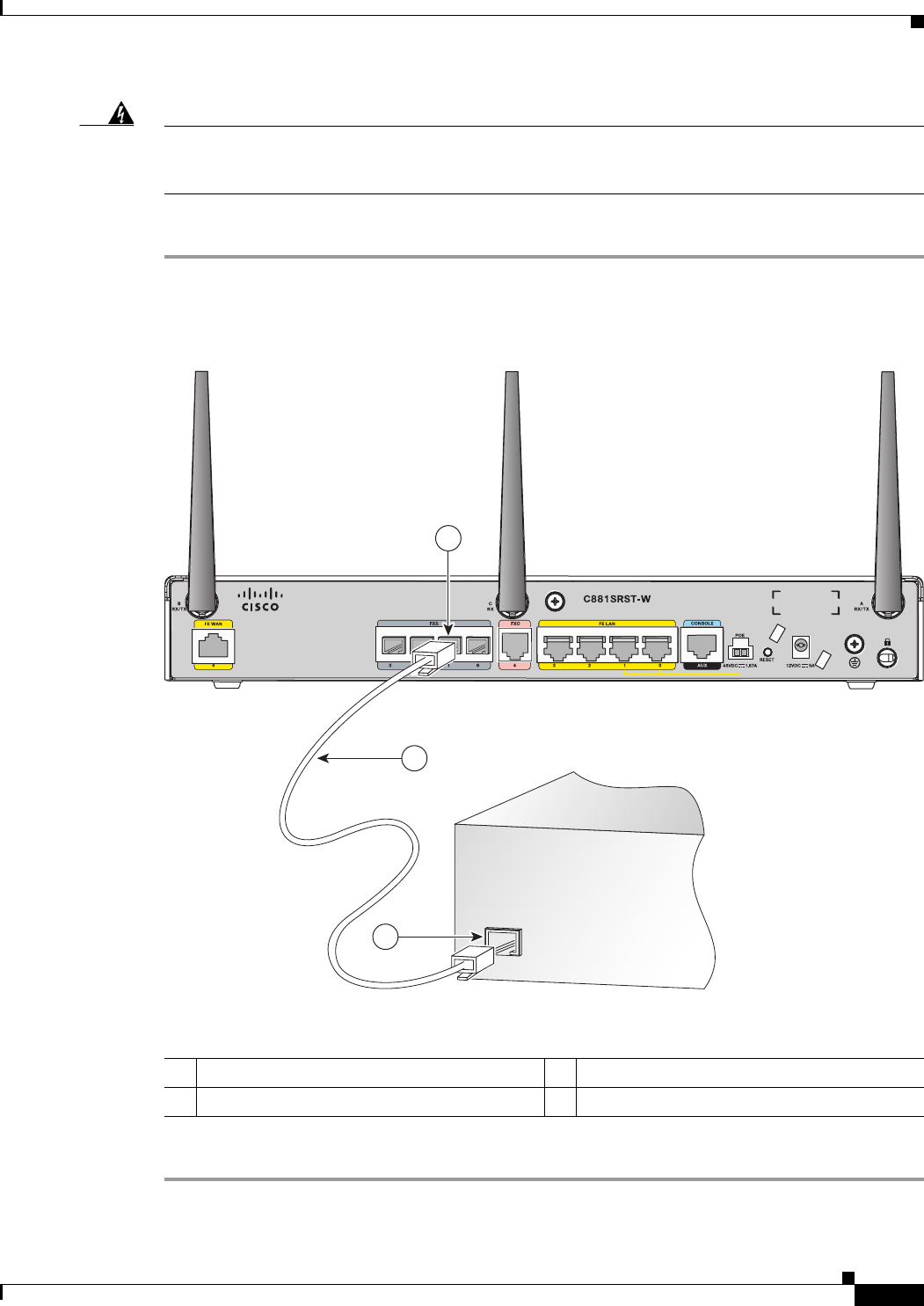
Step 1 Connect one end of the straight-through RJ-11 cable to the FXS port. Figure 3-30 shows an FXS line
connection.
Figure 3-30 Connecting an FXS Line
Step 2 Connect the other end of the cable to the RJ-11 port on the fax machine or telephone.
1FXS port 3RJ-11 port
2RJ-11 cable
Fax machine
or telephone
241907
1
2
3
3-34
Cisco 860 Series, Cisco 880 Series, and Cisco 890 Series Integrated Services Routers Hardware Installation Guide
OL-16215-10
Chapter 3 Connecting the Router
Connecting an FXO Line
Connecting an FXO Line
Use a straight-through RJ-11 cable to connect the FXO voice port to the PSTN or PBX through a
telephone wall outlet.
Warning
Hazardous network voltages are present in WAN ports regardless of whether power to the unit is OFF
or ON. To avoid electric shock, use caution when working near WAN ports. When detaching cables,
detach the end away from the unit first.
Statement 1026
To connect the FXO line, follow these steps:
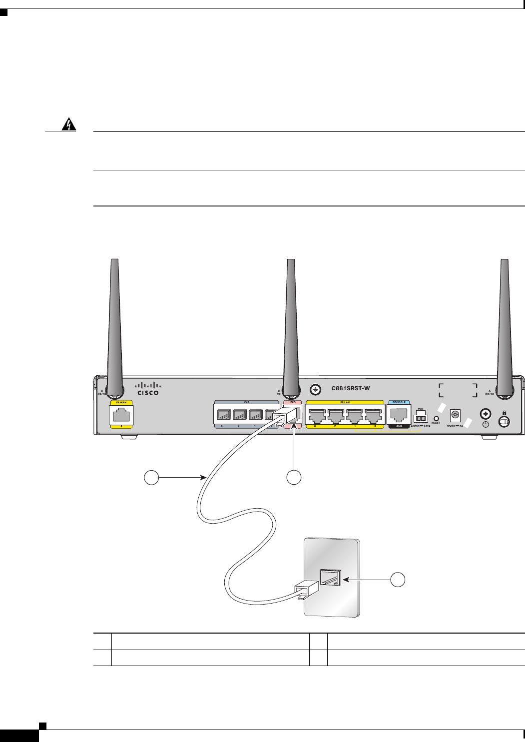
Step 1 Connect one end of the straight-through RJ-11 cable to the FXO port. See Figure 3-31.
Figure 3-31 Connecting an FXO Line
Step 2 Connect the other end of the RJ-11 cable to a telephone wall outlet.
1FXO port 3Telephone outlet
2RJ-11 cable
270542
21
3

3-35
Cisco 860 Series, Cisco 880 Series, and Cisco 890 Series Integrated Services Routers Hardware Installation Guide
OL-16215-10
Chapter 3 Connecting the Router
Connecting a Voice ISDN BRI Line
Note If you have specified the use of a private line automatic ringdown (PLAR) off-premises extension (OPX)
connection mode for an FXO voice port (with loop resistance less than 8000 Ohm), you must ensure that
the soft-offhook option is enabled on the port.
This option allows a stepped offhook resistance during seizure, which avoids overloading the circuit
during offhook in the event that ringing voltage is present on the circuit at the same time as the trunk
seizure. The stepped offhook resistance is initially set to 800 Ohms, then adjusts to 50 Ohms when
ringing voltage is not present.
To enable the soft-offhook command on the port, and to access the connection command with plar opx
syntax, see the Cisco Command Lookup Tool.
Connecting a Voice ISDN BRI Line
Use a straight-through RJ-45 cable to connect the voice BRI port to the ISDN network through a
telephone outlet or other device.
Caution To prevent damage to the router, be sure to connect the BRI cable to the BRI connector only and not to
any other RJ-45 connector.
To connect the voice BRI line, follow these steps:
Step 1 Connect one end of a straight-through RJ-45–to–RJ-45 cable to the Voice BRI port.
Note When the interface is configured as NT and is connecting to a TE device, use a crossover cable.
See Table A-13.
3-36
Cisco 860 Series, Cisco 880 Series, and Cisco 890 Series Integrated Services Routers Hardware Installation Guide
OL-16215-10
Chapter 3 Connecting the Router
Connecting a Voice ISDN BRI Line
Figure 3-32 shows a voice BRI line connection.
Figure 3-32 Connecting a Voice BRI Line
Step 2 Connect the other end of the cable to the RJ-45 telephone outlet or other device.
1Voice BRI port 3Telephone outlet
2RJ-45 cable
241906
1
3
2
3-37
Cisco 860 Series, Cisco 880 Series, and Cisco 890 Series Integrated Services Routers Hardware Installation Guide
OL-16215-10
Chapter 3 Connecting the Router
Connecting a Small Form-Factor Pluggable Module
Connecting a Small Form-Factor Pluggable Module
This section describes how to connect and remove a small form-factor (SFP) module and contains the
following information:
• Safety Warnings, page 3-37
• Installing an SFP Module, page 3-38
• Removing an SFP Module, page 3-38
• Online Insertion and Removal, page 3-39
Safety Warnings
Laser Safety Warnings
Optical SFPs use a small laser to generate the fiber-optic signal. Keep the optical transmit and receive
ports covered whenever a cable is not connected to the port.
Warning
Invisible laser radiation may be emitted from disconnected fibers or connectors. Do not stare into
beams or view directly with optical instruments.
Statement 1051
Warning
Do not stare into the laser beam.
Statement 1010
Warning
Invisible laser radiation present.
Statement 1016
Warning
Ultimate disposal of this product should be handled according to all national laws and regulations.
Statement 1040
Warning
Invisible laser radiation may be emitted from the end of the unterminated fiber cable or connector. Do
not view directly with optical instruments. Viewing the laser output with certain optical instruments
(for example, eye loupes, magnifiers, and microscopes) within a distance of 100 mm may pose an eye
hazard.
Statement 1056
Warning
Use of controls, adjustments, or performing procedures other than those specified may result in
hazardous radiation exposure.
Statement 1057
3-38
Cisco 860 Series, Cisco 880 Series, and Cisco 890 Series Integrated Services Routers Hardware Installation Guide
OL-16215-10
Chapter 3 Connecting the Router
Connecting a Small Form-Factor Pluggable Module
Installing an SFP Module
To connect and secure the SFP module, follow these steps:
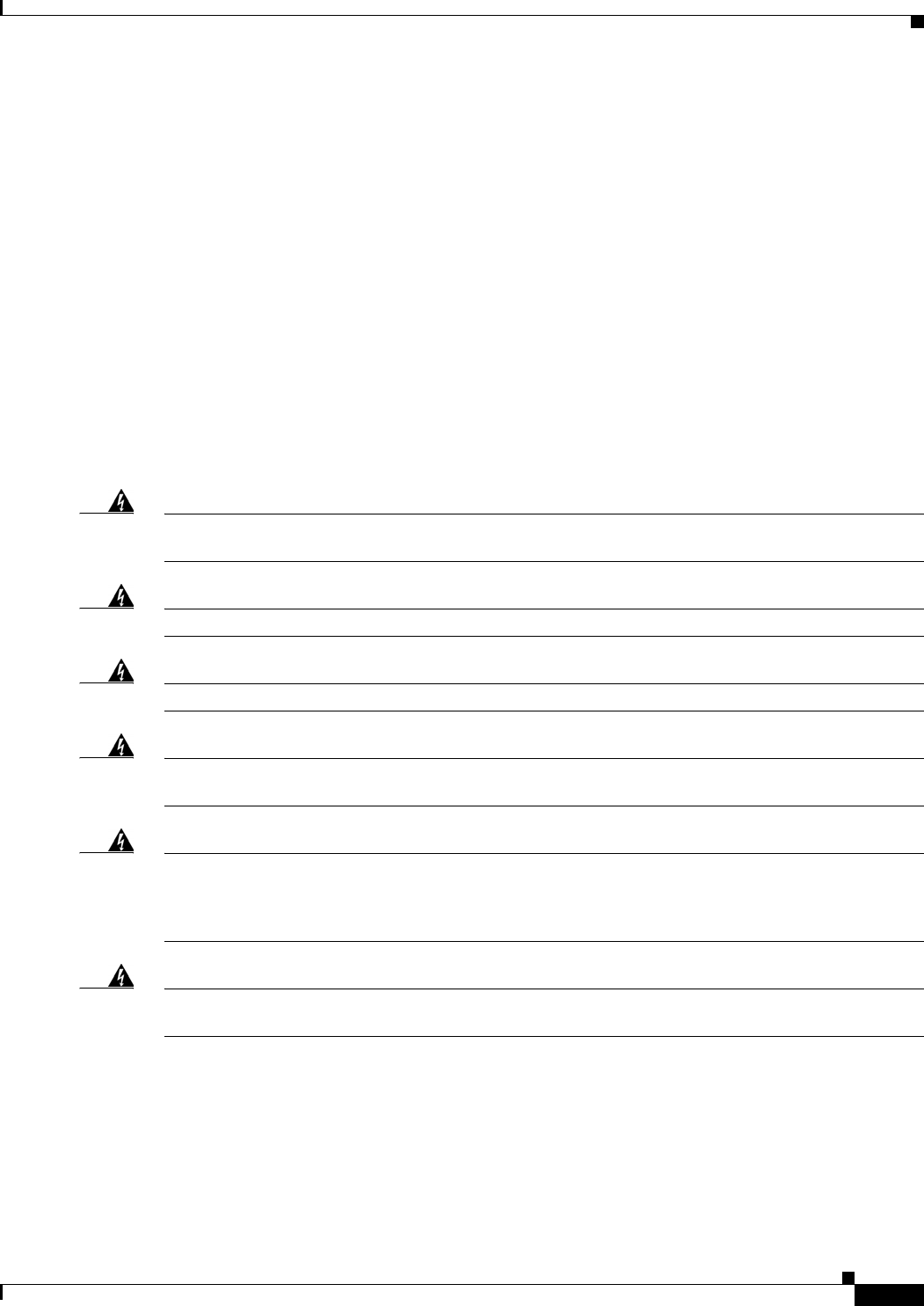
Step 1 Slide the SFP into the SFP port connector until it locks into position (see Figure 3-33).
Tip If the SFP uses a bale-clasp latch (see Figure 3-33), the handle should be on top of the SFP module.
Figure 3-33 Installing an SFP Module
Caution Do not remove the optical port plugs from the SFP until you are ready to connect cabling.
Step 2 Connect the network cable to the SFP module.
Removing an SFP Module
Follow these steps to remove the SFP module from a Cisco 892F series router:
Step 1 Disconnect all cables from the SFP.
Warning
Invisible laser radiation may be emitted from disconnected fibers or connectors. Do not stare into
beams or view directly with optical instruments.
Statement 1051
Caution The latching mechanism used on many SFPs locks the SFP into place when cables are connected. Do not
pull on the cabling in an attempt to remove the SFP.
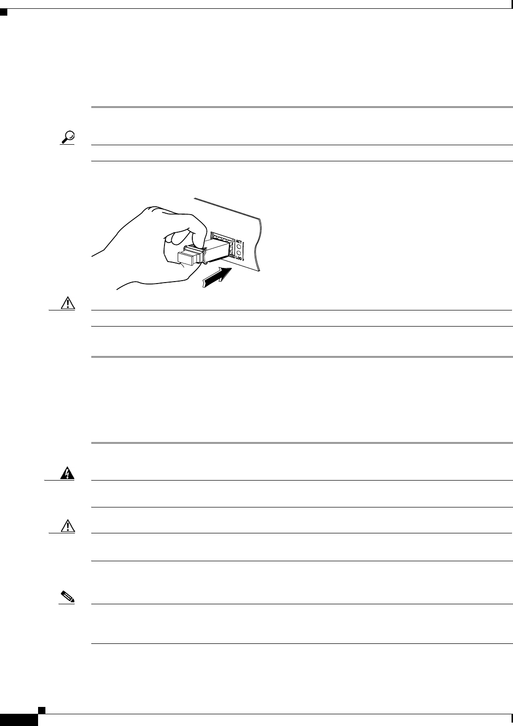
Step 2 Disconnect the SFP latch. See Figure 3-34.
Note SFP modules use various latch designs to secure the module in the SFP port. Latch designs are not linked
to SFP model or technology type. For information on the SFP technology type and model, see the label
on the side of the SFP.
94126
3-39
Cisco 860 Series, Cisco 880 Series, and Cisco 890 Series Integrated Services Routers Hardware Installation Guide
OL-16215-10
Chapter 3 Connecting the Router
Connecting a Small Form-Factor Pluggable Module
Figure 3-34 Figure 5-42 Disconnecting SFP Latch Mechanisms
Tip Use a pen, screwdriver, or other small straight tool to gently release a bale-clasp handle if you cannot
reach it with your fingers.
Step 3 Grasp the SFP on both sides and remove it from the router.
Online Insertion and Removal
Online insertion and removal (OIR) of the SFP module is supported on the Cisco 892F ISRs.
Note If an SFP module is inserted with auto-failover or SFP media-type already configured, the port is forced
to the speed and duplex capability of the SFP. For a 100 base SFP, the speed is set to 100 and duplex can
be configured to either half or full. For a 1000 base SFP, the speed is set to 1000 and duplex is set to full.
1Sliding latch 3Bale-clasp latch
2Swing and slide latch 4Plastic collar latch
117722
1 2 3 4
A
B

3-40
Cisco 860 Series, Cisco 880 Series, and Cisco 890 Series Integrated Services Routers Hardware Installation Guide
OL-16215-10
Chapter 3 Connecting the Router
Verifying Connections
Verifying Connections
To verify that all devices are properly connected to the router, first turn on all the connected devices,
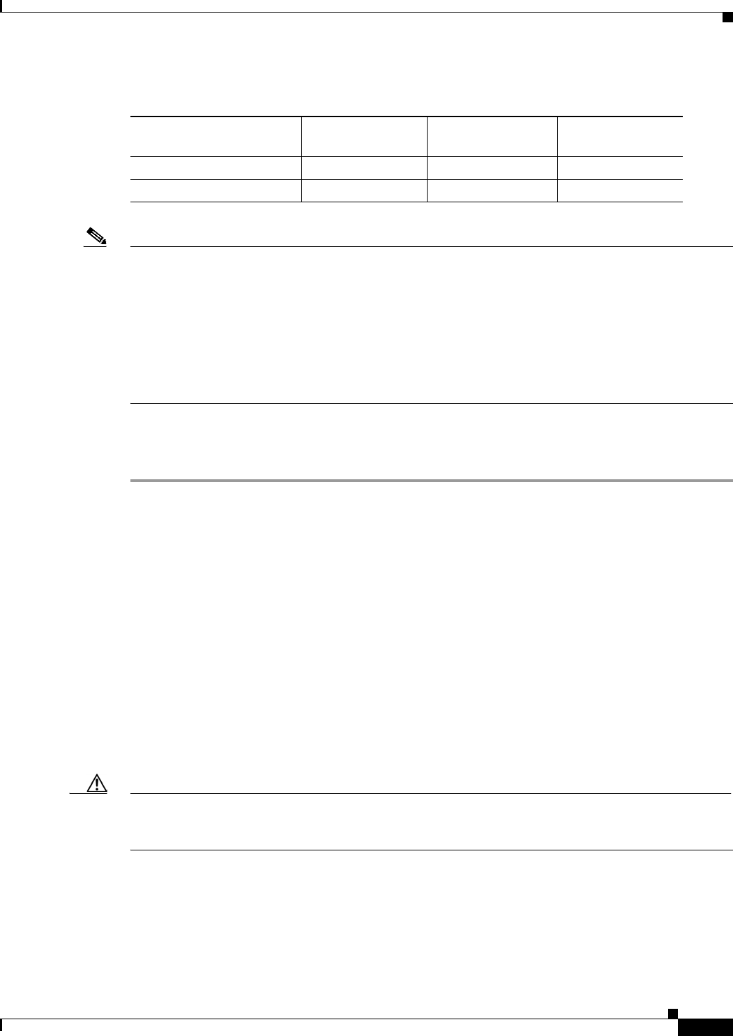
then check the LEDs. To verify router operation, refer to Table 3-3.
For the full LED descriptions, see the “LEDs” section on page 1-30.
Ta b l e 3-3 Verifying the Router Operation
Power and Link LEDs to Check Normal Patterns
Power OK On when power is supplied to the router.
To servers, PCs,
workstations, or an
external Ethernet
switch connected to
the LAN ports
(FE01, FE1, FE2, or
FE3)
LAN 0, LAN 1,
LAN 2, or LAN 3 On when the FE LAN port is physically connected to a
server, PC, workstation, or external Ethernet switch.
To FE WAN line WAN FE4 On when the WAN Ethernet carrier has detected status.
Blinks when receiving or transmitting data.
To xDSL2 line xDSL CD Green when the line is connected to the xDSL DSLAM3.
xDSL Data Green when receiving or sending data.
Blinks when line is in training mode.
ATM 898EA only Green when ATM mode is selected.
EFM 898EA only Green when EFM mode is selected.
To ISDN line Data BRI LNK Green when the ISDN line is connected.
Data BRI B1 and
B2 Green when the channel is connected.
3G4WWAN5Green when service is established.
Slow blinking when searching for service.
RSSI6Amber when service is not established.
Green when signal strength is high.
Off or slow blinking when signal strength is low.
Fast blinking when signal strength is medium.
CDMA7Green when service is established.
GSM8Green when service is established.
To PPP9 clients PPP Green when either a PPPoE10 or PPPoA11 client is running.
To VPN12 tunnel VPN Green when a crypto session is running.
3-41
Cisco 860 Series, Cisco 880 Series, and Cisco 890 Series Integrated Services Routers Hardware Installation Guide
OL-16215-10
Chapter 3 Connecting the Router
Verifying Connections
To wireless LAN WLAN LINK Wireless LAN link status:
• Green if at least one client is associated.
• Off if no client is associated.
WLAN 2.4 GHz Wireless LAN 2.4-GHz status:
• Green when radio is connected, SSID13 is configured,
signal is being transmitted, and client is associated.
• Slow blinking when radio is connected, SSID is
configured, and signal is being transmitted.
WLAN 5.0 GHz Wireless LAN 5.0-GHz status:
• Green when radio is connected, SSID is configured,
signal is being transmitted, and client is associated.
• Slow blinking when radio is connected, SSID is
configured, and signal is being transmitted.
PoE14 PoE 0 (880 and
890 series only) PoE power status:
• Green when connected and powered.
• Amber when there is a fault with the inline power
supply.
PoE 1 (880 and
890 series only)
PoE 2 (890 series
only)
PoE 3 (890 series
only)
SFP15 EN Green when the interface is up.
SBlinking green indicates port speed. Slow blinking for
100Base SFPs and fast blinking for 1000Base SFPs.
To LAN GE/FE line
(860VAE models
only)
LAN Blinking when there is LAN activity (traffic in either
direction).
Off when the link is down.
Table 3-3 Verifying the Router Operation (continued)
Power and Link LEDs to Check Normal Patterns
3-42
Cisco 860 Series, Cisco 880 Series, and Cisco 890 Series Integrated Services Routers Hardware Installation Guide
OL-16215-10
Chapter 3 Connecting the Router
Verifying Connections
To DSL line
(860VAE models
only)
DSL LINK On when DSL WAN mode is selected and DSL training
complete.
Blinking when DSL WAN mode is selected but incomplete
DSL LinkUp state such as in-training (slow initially, fast
when almost connected), or controller "OFF", or no cable
attached to DSL connector.
Off when the device is powered off; or GE WAN mode is
selected.
DSL ACT On when the DSL interface is up.
Blinking when there is DSL WAN activity (traffic in either
direction).
Faster blinking when there is heavier traffic.
Off when the device is powered off or the DSL WAN
interface is down.
To WAN GE line
(860VAE models
only)
GE Mode On when GE WAN mode is selected.
Off when the device is powered off or when DSL WAN
mode is selected.
GE ACT On when the GE WAN interface is up.
Blinking when there is GE WAN activity (traffic in either
direction).
Off when the device is powered off or when the GE WAN
interface is down.
1. FE = Fast Ethernet.
2. xDSL = General term referring to various forms of DSL, including ADSL (asymmetric digital subscriber line), VDSL
(very-high-data-rate digital subscriber line), and G.SHDSL.
3. DSLAM = digital subscriber line access multiplexer.
4. 3G = Third-Generation.
5. WWAN = wireless WAN.
6. RSSI = Received Signal Strength Indicator.
7. CDMA = code division multiple access.
8. GSM = Global System for Mobile Communications.
9. PPP = Point-to-Point Protocol.
10. PPPoE = PPP over Ethernet.
11. PPPoA = PPP over ATM.
12. VPN = Virtual Private Network.
13. SSID = service set identifier.
14. PoE = Power over Ethernet.
15. SFP = small-form-factor pluggable.
Table 3-3 Verifying the Router Operation (continued)
Power and Link LEDs to Check Normal Patterns
CHAPTER
4-1
Cisco 860 Series, Cisco 880 Series, and Cisco 890 Series Integrated Services Routers Hardware Installation Guide
OL-16215-10
4
Initial Configuration
This chapter provides instructions for initial configuration of the Cisco 860 series, 880 series, and 890
series Integrated Services Routers (ISRs). For the initial configuration, we recommend using
Cisco Configuration Professional (CP) Express. Cisco CP Express is a web-based graphical user
interface that guides you through initial configuration.
You may also initially configure your router by using the Cisco IOS command-line interface (CLI) or by
using the setup command facility. To create the initial configuration, the setup command facility prompts
you for basic information about your router and network.
This chapter contains the following sections:
• Cisco Configuration Professional Express, page 4-1
• Cisco IOS CLI, page 4-1
• Setup Command Facility, page 4-3
• Verifying the Initial Configuration, page 4-5
• Initial Configuration of the Wireless Access Point, page 4-6
Note Some SKUs may not include a default configuration file. If your router does not have a default
configuration file, go to the “Setup Command Facility” section on page 3 to configure the initial router
settings.
Cisco Configuration Professional Express
After you connect the cables and power up the router, we recommend that you use the Cisco CP Express
web-based application to configure the initial router settings.
For instructions on how to use Cisco CP Express to configure the router see Cisco CP Express User’s
Guide.
Cisco IOS CLI
To configure the initial router settings by using the Cisco IOS CLI, you must set up a console connection.
For instructions on how to set up a console connection, see the “Connecting a Terminal or PC to the
Console Port” section on page 3-9.
4-2
Cisco 860 Series, Cisco 880 Series, and Cisco 890 Series Integrated Services Routers Hardware Installation Guide
OL-16215-10
Chapter 4 Initial Configuration
Cisco IOS CLI
To configure the initial router settings using the Cisco IOS CLI, follow these steps:
Step 1 Set up a console connection to your router. The following message is displayed:
...
router con0 is now available
Step 2 Press Return. The following message is displayed:
Cisco Configuration Professional Express (Cisco CP Express) is installed on this device.
This feature requires the one-time use of the username "username1"
with the password "password1." The default username and password have a privilege level of
15.
Please change these publicly known initial credentials using Cisco CP Express or the Cisco
IOS CLI.
Here are the Cisco IOS commands.
username <myuser> privilege 15 secret 0 <mypassword>
no username username1
Replace <myuser> and <mypassword> with the username and password you want to use.
For more information about Cisco CP please follow the instructions in the QUICK START
GUIDE for your router...
...
User Access Verification
Username:
Step 3 Enter the username username1, and press Return or Enter. The following prompt is displayed:
Password:
Step 4 Enter the password password1, and press Return or Enter. The following prompt is displayed:
Router#
A message is displayed that is similar to the first warning message. The message directs you to change
the username and password.
You are now in privileged EXEC mode.
Note You must change the username and password before you log off the router. You cannot use the
username username1 or password password1 after you log off from this session.
Step 5 Enter configuration mode using the following commands.
Router#
Router#config t
Router(config)#
Router(config)#username username privilege 15 secret 0 password
Step 6 To change the username and password, enter the following at the prompt:
username username privilege 15 secret 0 password
The username and password are the username and password that you determine.
To continue using the Cisco IOS CLI for initial configuration, see the applicable configuration
procedures in Cisco 860 Series, Cisco 880 Series, and Cisco 890 Series Integrated Services Routers
Software Configuration Guide.
4-3
Cisco 860 Series, Cisco 880 Series, and Cisco 890 Series Integrated Services Routers Hardware Installation Guide
OL-16215-10
Chapter 4 Initial Configuration
Setup Command Facility
Note Save your configuration changes regularly to avoid losing them during resets, power cycles, or
power outages. Use the copy running-config startup-config command at the privileged EXEC
mode prompt (Router#) to save the configuration to NVRAM.
Step 7 Verify the initial configuration. See the “Verifying the Initial Configuration” section on page 4-5.
Setup Command Facility
The setup command facility guides you through the configuration process by prompting you for the
specific information that is needed to configure your system. Use the setup command facility to
configure a hostname for the router, to set passwords, and to configure an interface for communication
with the management network.
To use the setup command facility, you must set up a console connection with the router and enter the
privileged EXEC mode.
Note For instructions on how to set up a console connection, see the “Connecting a Terminal or PC to
the Console Port” section on page 3-9.
To configure the initial router settings by using the setup command facility, follow these steps:
Step 1 Set up a console connection to your router, and enter privileged EXEC mode. For instructions on how to
enter privileged EXEC mode, see Step 1 through Step 4 in the “Cisco IOS CLI” section on page 4-1.
Step 2 In privileged EXEC mode, at the prompt, enter setup.
yourname# setup
The following message is displayed:
--- System Configuration Dialog ---
Continue with configuration dialog? [yes/no]:
You are now in the setup command facility.
The prompts in the setup command facility vary, depending on your router model, on the installed
interface modules, and on the software image. The following steps and the user entries (in bold) are
shown as examples only.
Note If you make a mistake while using the setup command facility, you can exit and run the setup
command facility again. Press Ctrl-C, and enter the setup command at the privileged EXEC
mode prompt (Router#). For more information on using the setup command facility, see “The
Setup Command” chapter in Cisco IOS Configuration Fundamentals Command Reference,
Release 12.2T.
Step 3 To proceed using the setup command facility, enter yes.
Continue with configuration dialog? [yes/no]: yes

4-4
Cisco 860 Series, Cisco 880 Series, and Cisco 890 Series Integrated Services Routers Hardware Installation Guide
OL-16215-10
Chapter 4 Initial Configuration
Setup Command Facility
Step 4 When the following messages appear, enter yes to enter basic management setup.
At any point you may enter a question mark '?' for help.
Use ctrl-c to abort configuration dialog at any prompt.
Default settings are in square brackets '[]'.
Basic management setup configures only enough connectivity
for management of the system, extended setup will ask you
to configure each interface on the system
Would you like to enter basic management setup? [yes/no]: yes
Step 5 Enter a hostname for the router (this example uses Router).
Configuring global parameters:
Enter host name [Router]: Router
Step 6 Enter an enable secret password. This password is encrypted (more secure) and cannot be seen when
viewing the configuration.
The enable secret is a password used to protect access to
privileged EXEC and configuration modes. This password, after
entered, becomes encrypted in the configuration.
Enter enable secret: xxxxxx
Step 7 Enter an enable password that is different from the enable secret password. This password is not
encrypted (less secure) and can be seen when viewing the configuration.
The enable password is used when you do not specify an
enable secret password, with some older software versions, and
some boot images.
Enter enable password: xxxxxx
Step 8 Enter the virtual terminal password, which prevents unauthenticated access to the router through ports
other than the console port.
The virtual terminal password is used to protect
access to the router over a network interface.
Enter virtual terminal password: xxxxxx
Step 9 Respond to the following prompts as appropriate for your network.
Configure SNMP Network Management? [yes]:
Community string [public]:
A summary of the available interfaces is displayed.
Step 10 Choose one of the available interfaces for connecting the router to the management network.
Enter interface name used to connect to the
management network from the above interface summary: fastethernet4
Step 11 Respond to the following prompts as appropriate for your network.
Configuring interface FastEthernet4:
Use the 100 Base-TX (RJ-45) connector? [yes]: yes
Operate in full-duplex mode? [no]: yes
Configure IP on this interface? [yes]: yes
IP address for this interface: 172.1.2.3
Subnet mask for this interface [255.255.0.0] : 255.255.0.0
Class B network is 172.1.0.0, 26 subnet bits; mask is /16

4-5
Cisco 860 Series, Cisco 880 Series, and Cisco 890 Series Integrated Services Routers Hardware Installation Guide
OL-16215-10
Chapter 4 Initial Configuration
Verifying the Initial Configuration
The configuration is displayed:
The following configuration command script was created:
hostname Router
enable secret 5 $1$D5P6$PYx41/lQIASK.HcSbfO5q1
enable password xxxxxx
line vty 0 4
password xxxxxx
snmp-server community public
!
no ip routing
!
interface FastEthernet4
no shutdown
speed 100
duplex auto
ip address 172.1.2.3 255.255.0.0
!
Step 12 Respond to the following prompts. Enter 2 to save the initial configuration.
[0] Go to the IOS command prompt without saving this config.
[1] Return back to the setup without saving this config.
[2] Save this configuration to nvram and exit.
Enter your selection [2]: 2
Building configuration...
Use the enabled mode 'configure' command to modify this configuration.
Press RETURN to get started! RETURN
The user prompt is displayed.
Router>
Step 13 Verify the initial configuration. See the “Verifying the Initial Configuration” section on page 4-5 for
verification procedures.
After the initial configuration file is created, you can use the Cisco IOS CLI to perform additional
configuration.
Verifying the Initial Configuration
To verify that the new interfaces are operating correctly, perform the following tests:
• To verify that the interfaces and line protocol are in the correct state—up or down—enter the show
interfaces command.
• To display a summary status of the interfaces configured for IP, enter the show ip interface brief
command.
• To verify that you configured the correct hostname and password, enter the show configuration
command.
After you complete and verify the initial configuration, you can configure your Cisco router for specific
functions.

4-6
Cisco 860 Series, Cisco 880 Series, and Cisco 890 Series Integrated Services Routers Hardware Installation Guide
OL-16215-10
Chapter 4 Initial Configuration
Initial Configuration of the Wireless Access Point
Initial Configuration of the Wireless Access Point
The embedded wireless access point (AP) runs its own IOS. You can initially configure the embedded
wireless AP by using one of the following methods:
• Cisco Configuration Professional (CP) Express
• Setup command facility on the embedded wireless device
For information on how to do basic wireless configuration on your router see the “Basic Wireless
Device” chapter of the Cisco 860 Series, Cisco 880, and Cisco 890 Series Integrated Services Routers
Software Configuration Guide.
A-1
Cisco 860 Series, Cisco 880 Series, and Cisco 890 Series Integrated Services Routers Hardware Installation Guide
OL-16215-10
APPENDIX
A
Technical Specifications
This appendix provides router, port, and cabling specifications for the Cisco 860 series, Cisco 880 series,
and Cisco 890 series Integrated Services Routers (ISRs). It contains the following sections:
• Router Specifications, page A-2
• Wireless Access Point, page A-3
• FE and GE Port Pinouts, page A-3
• Console and Auxiliary Port Connector Pinouts, page A-4
• FXS and FXO Port Connector Pinouts, page A-5
• VDSL2 Port Connector Pinouts, page A-5
• ADSL2+ Port Connector Pinouts, page A-5
• V.92 Port Connector Pinouts, page A-6
• G.SHDSL Port Connector Pinouts, page A-6
• Data BRI Port Connector Pinouts, page A-7
• Voice ISDN BRI Interface Pin Numbers and Functions, page A-7
• SFP Port Connector Pinouts, page A-8
• Cable Specifications, page A-8
Warning
Ultimate disposal of this product should be handled according to all national laws and regulations.
Statement 1040
Note For compliance and safety information, see Regulatory Compliance and Safety Information Roadmap
that was shipped with the router and Regulatory Compliance and Safety Information for Cisco 800 Series
and SOHO Series Routers.
Note The product has some color variation on the Power Pin. This will not impact product performance or
reliability.
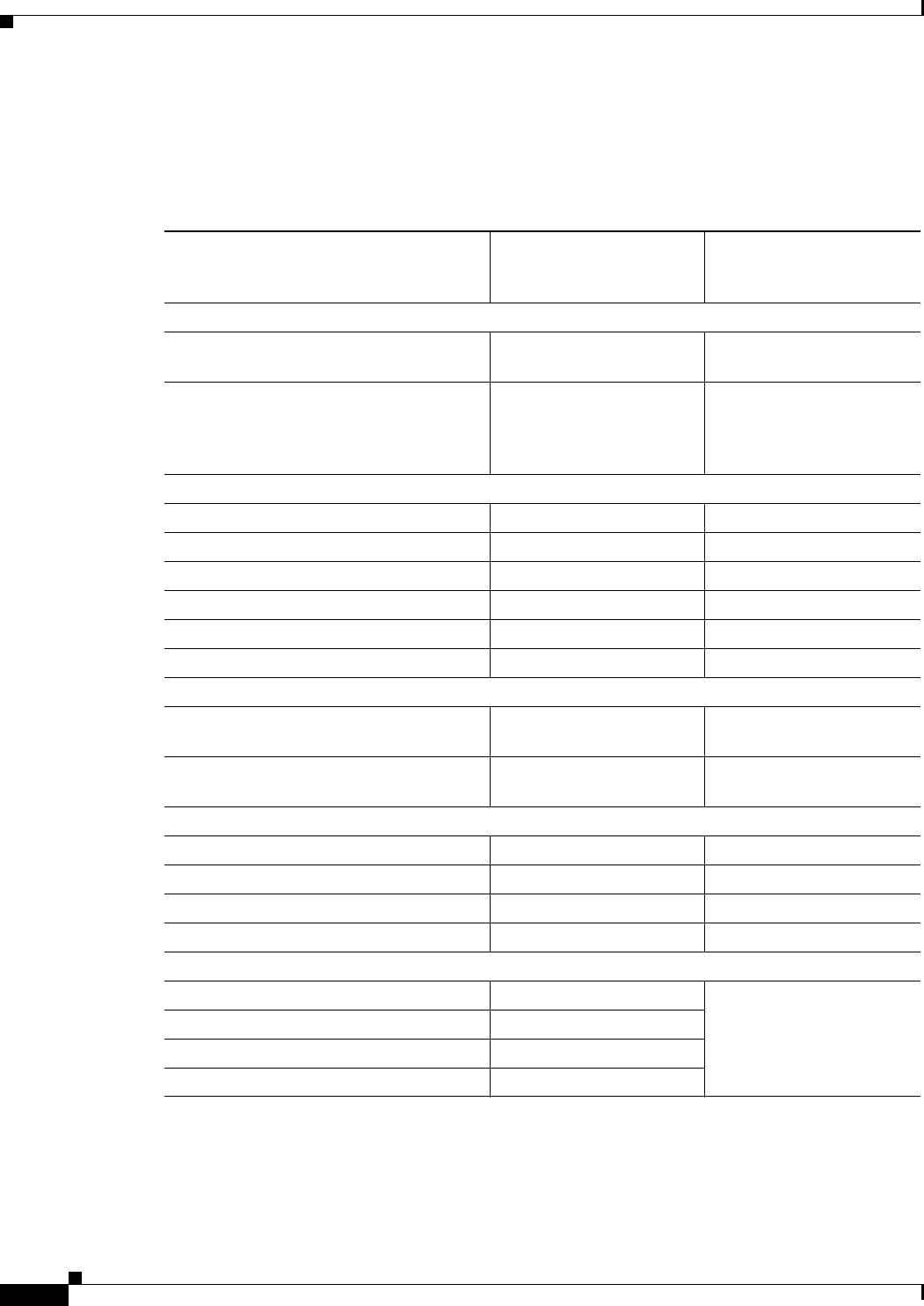
A-2
Cisco 860 Series, Cisco 880 Series, and Cisco 890 Series Integrated Services Routers Hardware Installation Guide
OL-16215-10
Appendix A Technical Specifications
Router Specifications
Router Specifications
Table A-1 lists the system specifications for the routers.
Ta b l e A-1 Router Specifications
Description
Design Specification
(all models except
Cisco 860VAE series)
Design Specification
Cisco 860VAE series
Physical Dimensions
Dimensions with antenna and rubber
feet (H x W x D) 1.9 x 12.8 x 10.4 in. 1.75 x 9.5 x 9 in.
Weight (not including desktop power
supply)5.5 lb (2.5 kg), maximum 3 lb (1.4 kg)
The total weight depends
on customer-selected
options.
Environmental Operating Ranges
Nonoperating temperature –4 to 149°F (–20 to 65°C) –4 to 149°F (–20 to 65°C)
Nonoperating humidity 5 to 95% relative humidity 5 to 95% relative humidity
Nonoperating altitude 0 to 15,000 ft (4570 m) 0 to 15,000 ft (4570 m)
Operating temperature 32 to 104°F (0 to 40°C) 32 to 104°F (0 to 40°C)
Operating humidity 10 to 85% relative humidity 10 to 85% relative humidity
Operating altitude 0 to 10,000 ft (3000 m) 0 to 10,000 ft (3000 m)
Acoustic
Acoustic: Sound Pressure
(Typical/Maximum) Low speed 31.4 dBa
High speed 44.1 dBa N/A, no fan
Acoustic: Sound Power
(Typical/Maximum) Low speed 38.9 dBA
High speed 51.7 dBa N/A, no fan
Router Power Adapter
Input voltage 100 to 240 VAC Nominal 100 to 240 VAC Nominal
Input frequency 47 to 63 Hz 47 to 63 Hz
Power output 60 W, maximum 30 W, maximum
Output voltages +12 VDC +12 VDC
Inline Power-over-Ethernet Adapter
Input voltage 85 to 264 VAC not supported
Input frequency 47 to 63 Hz
Power output 80 W, maximum
Output voltage –48 VDC
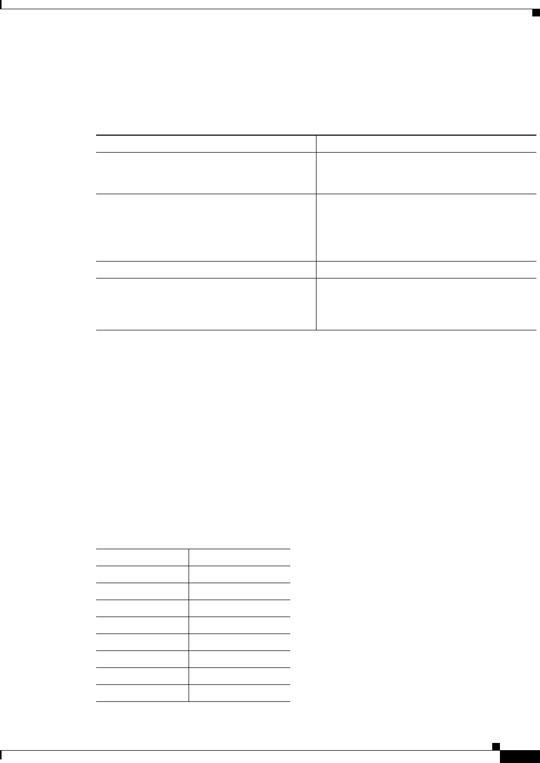
A-3
Cisco 860 Series, Cisco 880 Series, and Cisco 890 Series Integrated Services Routers Hardware Installation Guide
OL-16215-10
Appendix A Technical Specifications
Wireless Access Point
Wireless Access Point
Table A-2 lists the specifications for the wireless access point (AP).
FE and GE Port Pinouts
Table A-3 describes the RJ-45 connector pinouts for Fast Ethernet (FE) ports with Power over Ethernet
(PoE). Some models support PoE using an optional module, and some models do not support PoE. For
ports that do not support PoE, pins 4, 5, 7, and 8 are not connected.
• Cisco 860VAE and 860VAE-K9 ISRs do not support PoE.
• Cisco 880 series ISRs can include an optional PoE module that provides power to 802.3af-compliant
devices connected to FE ports 0 and 1.
• Cisco 890 series ISRs can include an optional PoE module that provides power to 802.3af-compliant
devices connected to FE ports 0, 1, 2, and 3.
Ta b l e A-2 Wireless Access Point Specifications
Description Design Specification
Radio technology IEEE 802.11n draft 2.0 standard compliant. 2x3
MIMO1 radio. Backward compatible with
802.11b/g and 802.11a (Cisco 890 series routers).
1. MIMO = Multiple Input/Multiple Output.
Operating frequency Cisco 860 series and 880 series ISRs
2.4-GHz radio band
Cisco 890 series ISRs
2.4 and 5-GH radio bands
Channels Country-specific 20 and 40 MHz
PHY Data rate 802.11b up to 11 Mb/s
802.11g up to 54 Mb/s
802.11n up to 300 Mb/s
Ta b l e A-3 Ethernet FE LAN Port Pinouts
Pin Function
1RX+1
2RX–
3TX+2
4PoE—optional
5PoE—optional
6TX–
7PoE—optional
8PoE—optional
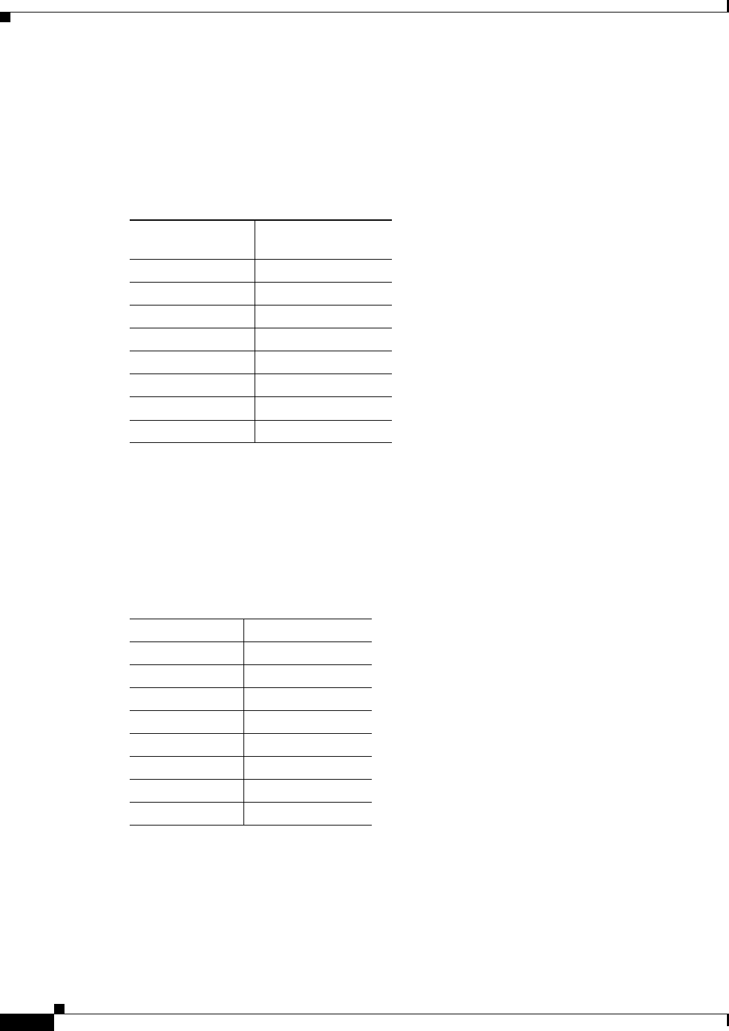
A-4
Cisco 860 Series, Cisco 880 Series, and Cisco 890 Series Integrated Services Routers Hardware Installation Guide
OL-16215-10
Appendix A Technical Specifications
Console and Auxiliary Port Connector Pinouts
Table A-4 describes the RJ-45 connector pinouts for the Gigabit Ethernet (GE) ports of the Cisco
860VAE and 860VAE-K9 ISRs.
Console and Auxiliary Port Connector Pinouts
Table A-5 lists the pinouts for the console and auxiliary port connectors.
1. RX = Receive
2. TX = Transmit
Ta b l e A-4 Ethernet GE Port Pinouts
Pin
GE Signal
(LAN and WAN)
1Tx A+1
1. TX = Transmit
2Tx A-
3Rx B+2
2. RX = Receive
4Tx C+
5Tx C-
6Rx B-
7Rx D+
8Rx D-
Ta b l e A-5 Console and Auxiliary Port Connector Pinouts
RJ-45 Pin Function
1RTS
2DTR
3TXD
4GND
5GND
6RXD
7DSR
8CTS
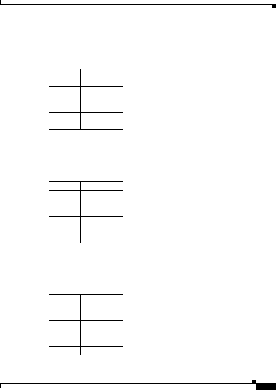
A-5
Cisco 860 Series, Cisco 880 Series, and Cisco 890 Series Integrated Services Routers Hardware Installation Guide
OL-16215-10
Appendix A Technical Specifications
FXS and FXO Port Connector Pinouts
FXS and FXO Port Connector Pinouts
Table A-6 lists the FXS and FXO connector pinouts.
VDSL2 Port Connector Pinouts
Table A-7 lists the VDSL2 connector pinouts.
ADSL2+ Port Connector Pinouts
Table A-8 lists the ADSL2+ connector pinouts.
Ta b l e A-6 FXS and FXO Connector Pinouts (RJ-11-to-RJ-45)
Pin Signal
1NC
2NC
3TIP
4RING
5NC
6NC
Ta b l e A-7 VDSL2 Connector Pinouts (RJ-11-to-RJ-45)
RJ-11 Pin Function
1Unused
2Unused
3TIP
4RING
5Unused
6Unused
Ta b l e A-8 ADSL2+ Connector Pinouts (RJ-11)
RJ-11 Pin Function
1Unused
2Unused
3TIP
4RING
5Unused
6Unused

A-6
Cisco 860 Series, Cisco 880 Series, and Cisco 890 Series Integrated Services Routers Hardware Installation Guide
OL-16215-10
Appendix A Technical Specifications
V.92 Port Connector Pinouts
V.92 Port Connector Pinouts
Table A-9 lists the V.92 connector pinouts.
G.SHDSL Port Connector Pinouts
Table A-10 lists the pinouts for the symmetrical high-speed DSL (G.SHDSL) WAN port for two-pair
products, including the following router model(s):
• C888
Table A-11 lists the pinouts for the symmetrical high-speed DSL (G..SHDSL) WAN port for four-pair
products, including the following router models:
• C888E
• C888EW
• C888EA
Ta b l e A-9 V.92 Connector Pinouts (RJ-11-to-RJ-45)
RJ-11 Pin Function
1Unused
2Unused
3TIP
4RING
5Unused
6Unused
Ta b l e A-10 G.SHDSL WAN Port Pinouts for Two-Pair Products
Pin Function
1Unused
2TIP (Port1)
3TIP (Port0)
4RING (Port0)
5RING (Port1)
6Unused
Ta b l e A-11 G.SHDSL WAN Port Pinouts for Four-Pair Products
Pin Function
1TIP (Port1)
2RING (Port1)
3TIP (Port2)
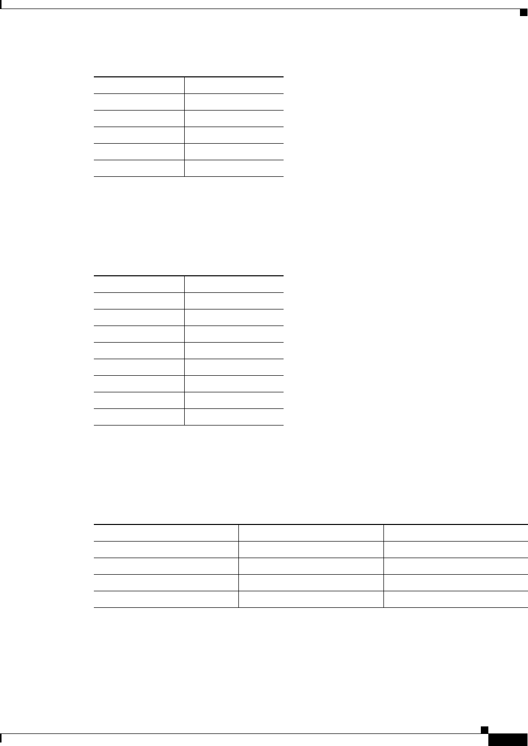
A-7
Cisco 860 Series, Cisco 880 Series, and Cisco 890 Series Integrated Services Routers Hardware Installation Guide
OL-16215-10
Appendix A Technical Specifications
Data BRI Port Connector Pinouts
Data BRI Port Connector Pinouts
Table A-12 lists the pinouts for the Data BRI port.
Voice ISDN BRI Interface Pin Numbers and Functions
Table A-13 lists the interface pin numbers and functions for the voice ISDN BRI port.
4TIP (Port0)
5RING (Port0)
6RING (Port2)
7TIP (Port3)
8RING (Port3)
Table A-11 G.SHDSL WAN Port Pinouts for Four-Pair Products (continued)
Pin Function
Ta b l e A-12 Data BRI Port Pinouts
Pin Function
1Unused
2Unused
3TXP
4RXP
5TXN
6TXN
7Unused
8Unused
Ta b l e A-13 Interface Pin Numbers and Functions
ISDN BRI NT/TE Card NT Interface1
1. Use a straight-through cable for NT interfaces.
TE Interface2
2. Use a crossover cable for TE interfaces.
Pin 3/T+ Pin 3/R+ Pin 3/T+
Pin 4/R+ Pin 4/T+ Pin 4/R+
Pin 5/R- Pin 5/T- Pin 5/R-
Pin 6/T- Pin 6/R- Pin 6/T-

A-8
Cisco 860 Series, Cisco 880 Series, and Cisco 890 Series Integrated Services Routers Hardware Installation Guide
OL-16215-10
Appendix A Technical Specifications
SFP Port Connector Pinouts
SFP Port Connector Pinouts
Table A-14 lists the pinouts for the SFP port.
Cable Specifications
This section provides specifications for the following Ethernet cables:
• Straight-through cable
• Crossover cable
Because of the autocrossover (autosensing) function, both straight-through and crossover cables can be
used for the Ethernet LAN port.
Ta b l e A-14 SFP Port Pinouts
Pin Function
1TX Ground
2TX Fault
3TX disable
4Module definition 2
5Module definition 1
6Module definition 0
7Rate Select
8Loss of signal
9Receiver ground
10 Receiver ground
11 Receiver ground
12 Inverted received data out
13 Received data out
14 Receiver ground
15 Receiver power
16 Transmitter power
17 Transmitter ground
18 Transmit data in
19 Inverted transmit data in
20 Transmitter ground

A-9
Cisco 860 Series, Cisco 880 Series, and Cisco 890 Series Integrated Services Routers Hardware Installation Guide
OL-16215-10
Appendix A Technical Specifications
Cable Specifications
Ethernet Cable Specifications
Table A-15 lists the specifications that apply to both straight-through and crossover Ethernet cables.
Maximum Cable Length
The maximum length for the Ethernet cables that connect equipment to the router is 328 feet
(100 meters). This length is also the maximum distance between the router and the equipment connected
to it.
Ta b l e A-15 Ethernet Cable Specifications
Type Category
10BASE-T Category 3 or 5
100BASE-T Category 5 or higher
1000BASE-T Category 5 or higher

A-10
Cisco 860 Series, Cisco 880 Series, and Cisco 890 Series Integrated Services Routers Hardware Installation Guide
OL-16215-10
Appendix A Technical Specifications
Cable Specifications