General Dynamics Broand P1DKF2 Wireless Broadband Modem User Manual Integration Instructions
General Dynamics Broadband, Inc. Wireless Broadband Modem Integration Instructions
Contents
- 1. User Manual
- 2. Integration Instructions
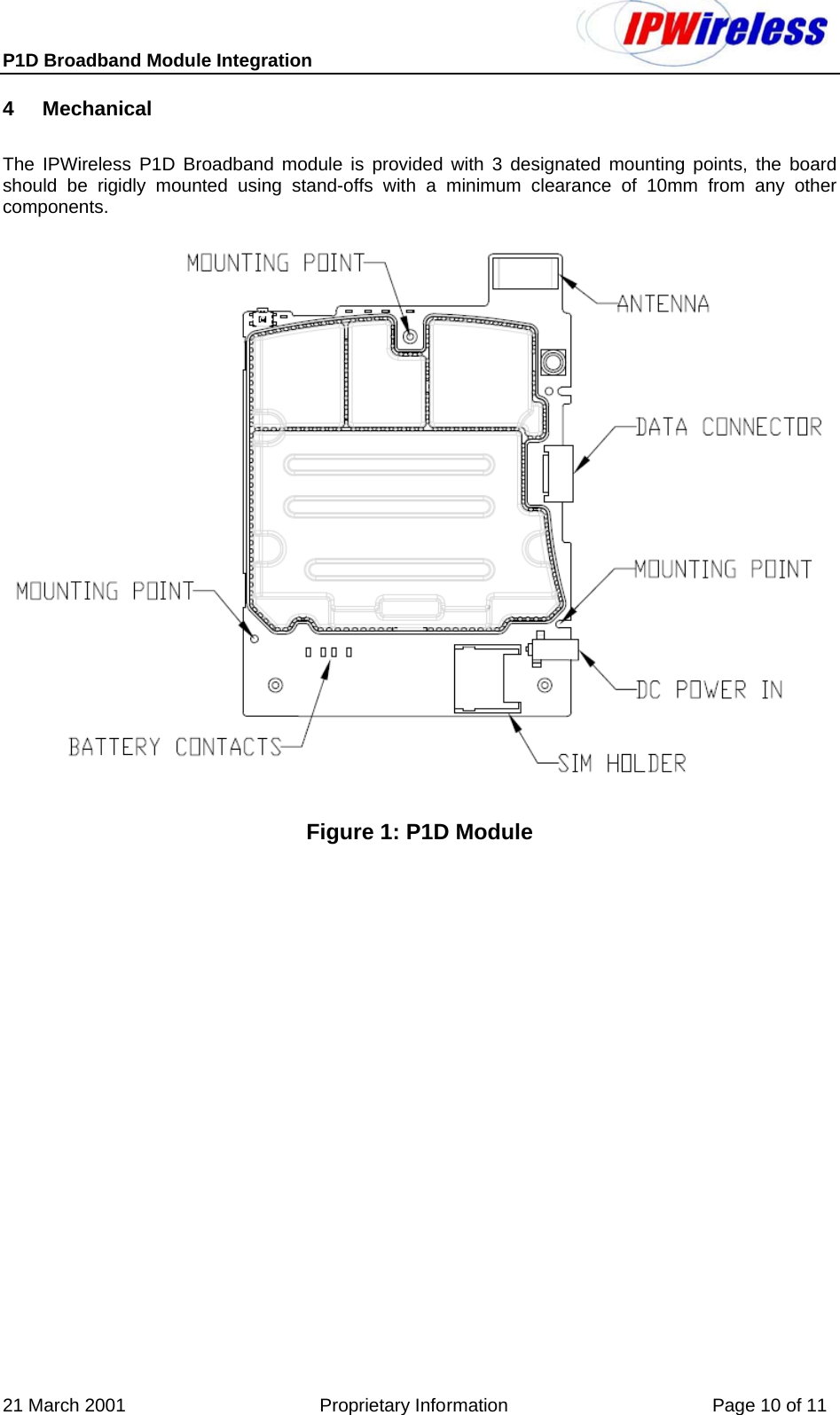
Integration Instructions