General Dynamics Broand P1DKF2 Wireless Broadband Modem User Manual Integration Instructions
General Dynamics Broadband, Inc. Wireless Broadband Modem Integration Instructions
Contents
- 1. User Manual
- 2. Integration Instructions
Integration Instructions

P1D Broadband Module Integration
21 March 2001 Proprietary Information Page 1 of 11
IPWireless P1D Module
Integration Instructions
DRAFT
V00.02

P1D Broadband Module Integration
21 March 2001 Proprietary Information Page 2 of 11

P1D Broadband Module Integration
21 March 2001 Proprietary Information Page 3 of 11
Contents
1General............................................................................................................................................ 5
1.1Approvals and Dates ............................................................................................................... 5
1.2Change Record ....................................................................................................................... 5
1.3Acronyms ................................................................................................................................ 6
1.4External References ................................................................................................................ 6
2Introduction ..................................................................................................................................... 7
2.1Scope of Document ................................................................................................................. 7
2.2Overview of Module ................................................................................................................ 7
3Module Connections ....................................................................................................................... 8
3.1Data Interface J2 ..................................................................................................................... 8
3.1.1Universal Serial Bus ........................................................................................................ 8
3.1.2Ethernet ........................................................................................................................... 8
3.2J2 Connector ........................................................................................................................... 8
3.2.1Connector Type ............................................................................................................... 8
3.2.2Pin Out ............................................................................................................................ 8
3.3DC Power Input J1 .................................................................................................................. 9
3.4Battery Contact J3 ................................................................................................................... 9
3.5SIM Holder Socket 2 ............................................................................................................... 9
4Mechanical .................................................................................................................................... 10
5Regulatory Information .................................................................................................................. 11
5.1Compliance with FCC Rules and Regulations ...................................................................... 11
5.2Exposure to Radio Frequency Signals .................................................................................. 11
Figures
Figure 1: P1D Module ........................................................................................................................... 10
Tables
Table 1: 18 way Data Connector ............................................................................................................ 9

P1D Broadband Module Integration
21 March 2001 Proprietary Information Page 4 of 11
P1D Broadband Module Integration
21 March 2001 Proprietary Information Page 5 of 11
1 General
1.1 Approvals and Dates
Approval Date
W. J. Jones
1.2 Change Record
Date Version Author Reason For Change Issue
06/11/2007 00.00 PFW New Document.
24/01/2007 00.01 PFW Update for external antenna.
05/02/2008 00.02 PFW Typographical changes.

P1D Broadband Module Integration
21 March 2001 Proprietary Information Page 6 of 11
1.3 Acronyms
Term Definition
LED Light Emitting Diode
MPE Maximum Permissible Exposure
OEM Original Equipment Manufacturer
P1D Phase 1D
SIM Subscriber Identity Module
TDD Time Division Duplex
UMTS Universal Mobile Telephone System
USB Universal Serial Bus
1.4 External References
Ref
() Number Title
1 FCC Part 27
Note: Where a reference is undated, the latest version applies

P1D Broadband Module Integration
21 March 2001 Proprietary Information Page 7 of 11
2 Introduction
This document describes the method of integrating the IPWireless P1D Broadband module into an
OEM product.
2.1 Scope of Document
This document applies to the IPWireless P1D Broadband module only.
2.2 Overview of Module
The IPWireless P1D Broadband module provides a complete UMTS TDD wireless modem solution
and only requires the application of DC power and suitable data connection. The module is designed
to minimise the time and resource required to integrate.

P1D Broadband Module Integration
21 March 2001 Proprietary Information Page 8 of 11
3 Module Connections
3.1 Data Interface J2
The IPWireless P1D Broadband module is provided with an 18 pin data connector for connection to
the external application. This connection supports the following interface types and these are
described below.
3.1.1 Universal Serial Bus
The data interface provides a USB 1.1 interface. This is available on pins 1-4 of the data connector.
3.1.2 Ethernet
The data interface provides a 10Mbps Ethernet interface on pins 5-8, power is provided on pin 11 if a
link active LED is required.
3.2 J2 Connector
3.2.1 Connector Type
The mating connector is a Matushita 18-W AXR30241B101.
3.2.2 Pin Out
Connector Pin Description Comment
1 USB 5V In
2 USB Ground
3 USB D-
4 USB D+
5 Ethernet RXP
6 Ethernet RXN
7 Ethernet TXP
8 Ethernet TXN
9 Not Used
10 Not Used
11 Ethernet Transformer Power
12 Serial RTS
13 Serial RXD
14 Serial DSR

P1D Broadband Module Integration
21 March 2001 Proprietary Information Page 9 of 11
15 Serial CTS
16 Serial TXD
17 DTE Ground
18 Chassis Ground
G1, G2 Chassis Ground
Table 1: 18 way Data Connector
3.3 DC Power Input J1
The module requires a DC supply of 5VDC at upto 1A, the input voltage is required to be with ±5% of
nominal voltage. The connector type is a standard DC plug for 0.65mm centre pin configured as
centre positive.
3.4 Battery Contact J3
The module provides board contacts to allow an external battery pack to be used, connection to these
contact is made using spring fingers. The recommended battery is a lithium ion pack nominal voltage
3.7VDC, capacity 650mAh.
3.5 SIM Holder Socket 2
The IPWireless P1D Broadband module supports SIM authentication if required.
P1D Broadband Module Integration
21 March 2001 Proprietary Information Page 10 of 11
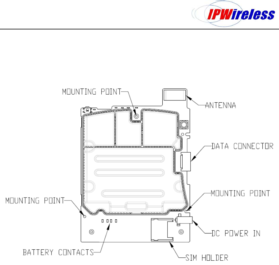
4 Mechanical
The IPWireless P1D Broadband module is provided with 3 designated mounting points, the board
should be rigidly mounted using stand-offs with a minimum clearance of 10mm from any other
components.
Figure 1: P1D Module

P1D Broadband Module Integration
21 March 2001 Proprietary Information Page 11 of 11
5 Regulatory Information
5.1 Compliance with FCC Rules and Regulations
The IPWireless P1D Broadband module is certified against FCC Part 27 for operation in the 2496-
2690MHz frequency allocation. The module is certified under FCC ID: PKTP1DKF2 and is only
certified for use with either an integral or external antenna, the maximum antenna gain allowed is
defined on the FCC Grant of Certification.
If the FCC ID is not visible from outside of the host device, then an additional label is required on
outside of the host device stating ‘Contains FCC ID: PKTP1DKF2’
IMPORTANT: Manufacturers of devices containing the IPWireless P1D Broadband module are
advised to
1. Clarify any regulatory questions.
2. Have their final product tested and approved for FCC compliance.
3. Include instructions with the final product regarding meeting RF Exposure requirements of the
FCC rules.
This device complies with Part 15 of the FCC Rules. Operation is subject to the following two
conditions: (1) this device may not cause harmful interference, and (2) this device must accept any
interference received, including interference that may cause undesired operation.
Caution: Changes or modifications not covered in this manual must be approved in writing by the
Manufacturer. Changes or modifications made without written approval may void the user’s authority
to operate this equipment.
5.2 Exposure to Radio Frequency Signals
To comply with the FCC RF exposure rules, the UE P1D wireless broadband modem has been
evaluated against the Maximum Permissible Exposure (MPE) limits defined in Section 1.1310 of the
FCC rules for the uncontrolled environment. During normal operation, all persons should maintain a
distance of at least 20cm from the antenna to ensure compliance with the MPE limits.