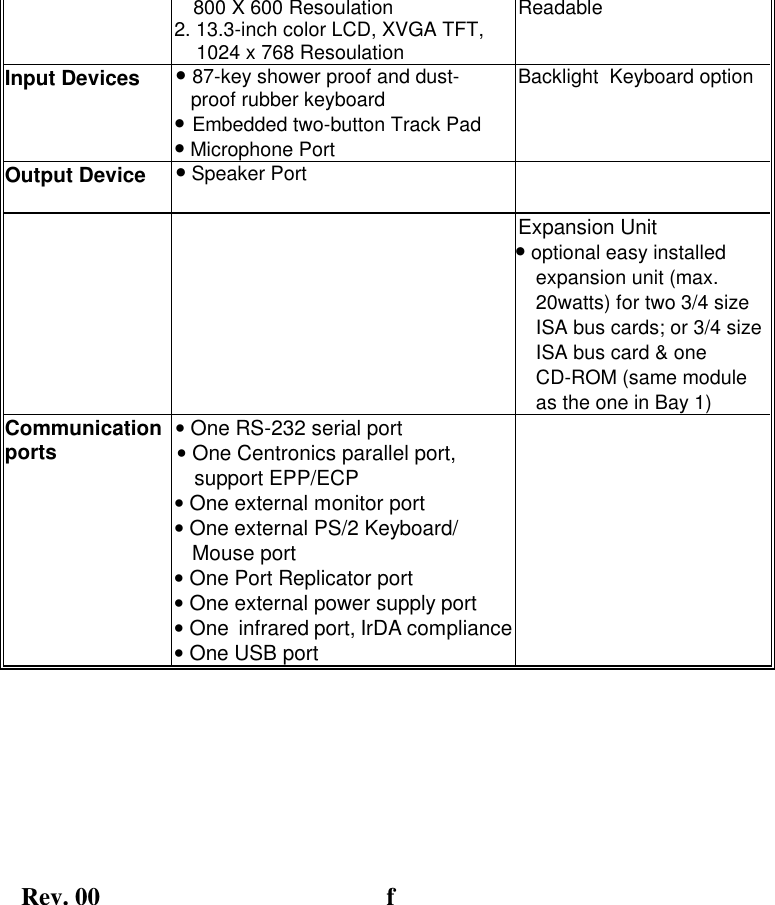
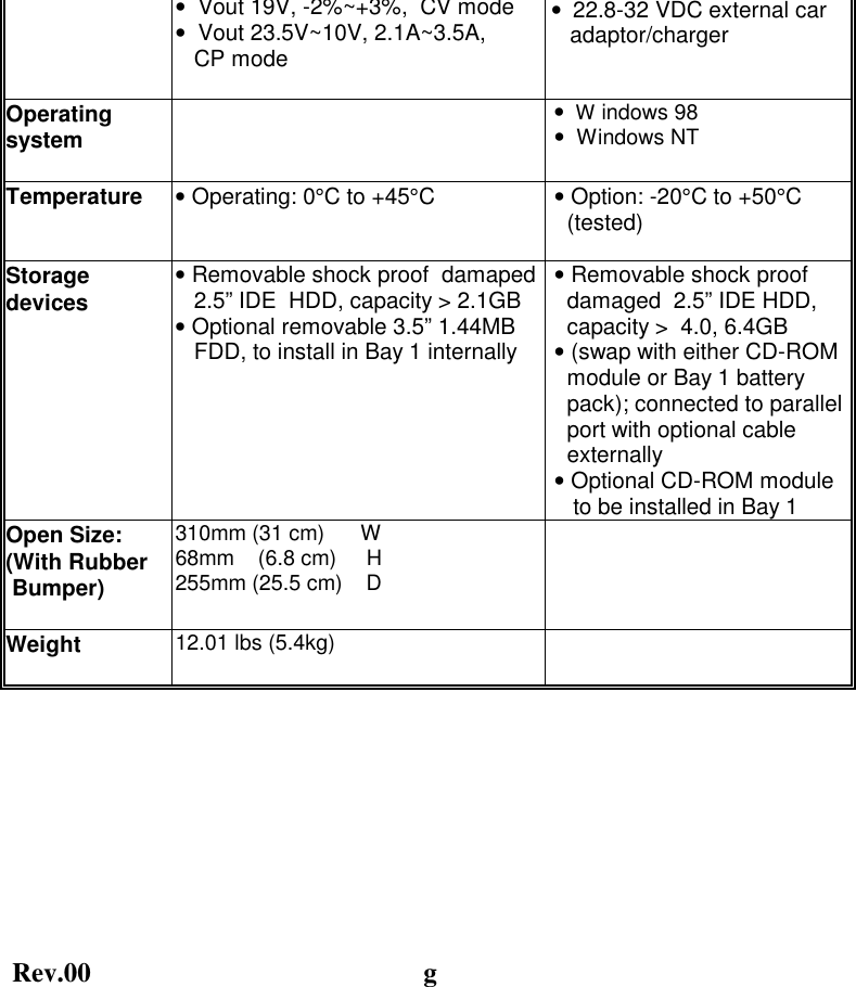
Getac Technology 007 Notebook PC User Manual N Series Notebook Guide Front Matter

Getac Technology Corp. Notebook PC N Series Notebook Guide Front Matter

users manual 1 of 6

    19-Nov-00     Prepared By: ______________ Reviewed By:_______________ Reviewed By:_______________ Reviewed By:_______________ Reviewed By:_______________ Approved By:______________  P/N:799001121001 R00
Rev.00  b
Rev.00  a       IBM, IBM PC/AT and OS/2 are registered trademarks of International Business Machines Corporation. Intel Pentium is a registered trademark of Intel Corporation. MS-DOS, XENEX, Windows 98 are registered trademarks of Microsoft Corporation. UNIX is a registered trademark of AT&T Bell Laboratories. Other brand and product names are trademarks and/or registered trademarks of their respective holders.
Rev.00  b gy ycause harmful interference to radio communications. However, there is no guarantee that interference will not occur in a particular installation. If this equipment does cause harmful interference to radio or television reception, which can be determined by turning the equipment off and on, the user is encouraged to try to correct the interference by one or more of the following measures:  Reorient or relocate the receiving antenna. Increase the separation between the equipment and receiver.  Connect the equipment into an outlet on a circuit different from that to which the receiver is connected. Consult the dealer or an experienced radio/TV technician for help. Any changes or modifications not expressly approved by the manufacturer could void the user’s authority to operate the equipment.  Please note: 1. The use of a non-shielded interface cable with this equipment is prohibited. 2. A shielded AC power cord must be used with this equipment.
Rev.00  c  ! EN61000-3-2: Current Harmonic  ! EN61000-3-3: Voltage Flicker ! EN50082-2: Electromagnetic compatibility-Generic immunity standard ! IEC1000-4-2: Electrostatic Discharge ! IEC1000-4-3: Radiated Susceptibility ! IEC1000-4-4: Electrical Fast Transients ! IEC1000-4-5: Surge Test ! IEC1000-4-6: Conducted Susceptibility ! IEC1000-4-11: Voltage Dip and Interruption
Rev.00  d
Rev.00  e With the exception of the SETUP configuration program,  which is part of the system firmware, this manual does not explain any of the software or devices used with the system.  Supplemental manuals or text-based documents on the hard disk supply information about any software included with the system. Audience All operators using the notebook in or out of the field should read and become familiar with this manual. Organization This manual has three chapters. Chapter 1 introduces the notebook pointing out its major features. Chapter 2 explains daily operation. Chapter 3 gives detailed information about configuring the notebook. Chapter 4  introduces the notebook Maintenance.  Supplemental Reading For further information about this computer and computing in general, use these references: •  A760T Series Service Manual for detailed troubleshooting and repair instructions for serious hardware problems associated with the A760T Series notebook. •  Various software manuals offer detailed instructions about individual programs run on the notebook.
Rev. 00   f     800 X 600 Resoulation 2. 13.3-inch color LCD, XVGA TFT,      1024 x 768 Resoulation Readable Input Devices  • 87-key shower proof and dust-    proof rubber keyboard  • Embedded two-button Track Pad • Microphone Port Backlight  Keyboard option Output Device  • Speaker Port     Expansion Unit • optional easy installed expansion unit (max. 20watts) for two 3/4 size ISA bus cards; or 3/4 size ISA bus card & one CD-ROM (same module as the one in Bay 1) Communication ports  • One RS-232 serial port • One Centronics parallel port,     support EPP/ECP • One external monitor port • One external PS/2 Keyboard/ Mouse port • One Port Replicator port • One external power supply port • One  infrared port, IrDA compliance • One USB port
Rev.00 g                  •  Vout 19V, -2%~+3%,  CV mode •  Vout 23.5V~10V, 2.1A~3.5A,     CP mode  •  22.8-32 VDC external car    adaptor/charger Operating system   •  W indows 98  •  Windows NT Temperature  • Operating: 0°C to +45°C   • Option: -20°C to +50°C    (tested)   Storage devices  • Removable shock proof  damaped    2.5” IDE  HDD, capacity > 2.1GB • Optional removable 3.5” 1.44MB    FDD, to install in Bay 1 internally  • Removable shock proof    damaged  2.5” IDE HDD,    capacity >  4.0, 6.4GB  • (swap with either CD-ROM    module or Bay 1 battery    pack); connected to parallel    port with optional cable    externally  • Optional CD-ROM module     to be installed in Bay 1  Open Size:  (With Rubber  Bumper)   310mm (31 cm)      W 68mm    (6.8 cm)     H 255mm (25.5 cm)    D  Weight  12.01 lbs (5.4kg)
Rev. 00   h gp p j p , ,next to the system unit. 5.  Use only batteries supplied with the system. 6.  Make sure any external power source connected to the adapter or system conforms with adaptor or system ratings. 7.  The external power adapter has a two-pronged grounding plug.  If an adapter is needed to plug the system into a power source, make sure the system is properly grounded. 8.  Arrange all cables so that they are out of traffic and unobstructed by personnel or equipment. 9.  Avoid using extension cords with this product. If an extension cord is needed, make sure it is rated for at least 10 amperes. 10.  Make sure amperage drawn by all items plugged into an outlet with this system does not exceed 15 amperes. 11.  Do not put any objects except those designed for use with this system inside the computer. 12. Observe proper electrical safety precautions when performing system maintenance. 13.  Replace any cables with identically rated cables as those included with the original equipment. 14.   Improper handling of the battery can cause personal injury  or fires. Do not attempt to disassemble or replace individual cells in the battery pack. Do not expose the battery to open flames. Do not short the positive and negative ends together even if the battery is fully discharged. Keep the battery away from children.
Rev. 00   i
Rev. 00   i  Contents...........................................................................................e  Audience ..........................................................................................e  Organization....................................................................................e  Supplemental Reading....................................................................e  Specifications  Specifications................................................................................... f  Safety Summary  Safety Summary..............................................................................h Chapter 1     System Overview 1-1 Introduction..................................................................................1-1 1-2 System Description ......................................................................1-1 1-3 System Configuration..................................................................1-1 1-3.1 Standard Configuration................................................1-1 1-3.2  Options and Accessories................................................1-2 1-3.3 System Identification.....................................................1-3
Rev. 00   ii 1-5.7 Brightness Control.........................................................1-8 1-5.8 Keyboard Backlight ......................................................1-8 1-5.9 CRT/LCD/Simulscan Toggle........................................1-8 1-5.10 Panel On/Off ..................................................................1-8 1-5.11 Standby Mode................................................................1-8 1-5.12 Suspend Mode................................................................1-8 1-5.13    Status Row......................................................................1-9 1-5.14 Battery Pack ................................................................1-10 1-5.15  Low Battery Indication...............................................1-10 1-5.16 Battery Charger...........................................................1-10 1-5.17  CHARGE LED Indicator Status................................1-11 1-5.18  Diskette Drive and CD-ROM .....................................1-12 1-5.19  PCMCIA Slot and Diskette Drive and CD-ROM Door1-13 1-5.20 PCMCIA Slot...............................................................1-13 1-5.21    VGA Port......................................................................1-14 1-5.22 Serial Port.....................................................................1-14 1-5.23 Printer Port ..................................................................1-14 1-5.24 VGA Port......................................................................1-14 1-5.25 IrDA Port......................................................................1-14 1-5.26 USB Port.......................................................................1-14 1-5.27 Keyboard/Mouse Port.................................................1-14 1-5.28  External Power Source Port .......................................1-14 1-5.29    External Power Adapter.............................................1-15 1-5.30  Reed Switch..................................................................1-15
Rev. 00   iii 2-2.2  Closing the Cover...........................................................2-2 2-2.3  Opening the PCMCIA/FDD/CD-ROM Door..............2-2 2-2.4  Shutting the PCMCIA/FDD/CD-ROM Door..............2-3 2-3  Connecting and Installing Devices.............................................2-3 2-3.1  Serial and Parallel Port.................................................2-3 2-3.2  External Power Adapter ...............................................2-4 2-3.3 Diskettes..........................................................................2-4 2-3-4  Remove the Floppy Diskette Drive and CD-ROM/ Bay 1               Battery ............................................................................2-5 2-3.5 PCMCIA Cards .............................................................2-6 2-3-6 Hard Disk .......................................................................2-7 2-4  First Time Use..............................................................................2-9 2-4.1  Configuring the System.................................................2-9 2-4.2  Installing Software Driver ............................................2-9 2-5 Daily Operation..........................................................................2-13 2-5.1  Starting the Computer ................................................2-13 2-5.2  Turning Off The Notebook.........................................2-14 2-5.3  Using the Notebook in the Car ...................................2-15 2.6  Using External Power Sources .................................................2-15 2-6.1  Using AC External Adaptor .......................................2-16 2-6.2  Charging the Batteries ................................................2-16 2-7  Running On Battery Power ......................................................2-16 2-8  Use the External FDD................................................................2-16
Rev. 00   iv 3-2.1  Main................................................................................3-3 3-2.2  Moving Around and making Selections ......................3-3 3-2.3 Security.........................................................................3-12 3-2.4 Power ............................................................................3-15 3-2.5 Exit................................................................................3-20 Chapter 4  Notebook Maintenance 4-1 Introduction................................................................................... 4-1 4-2 Daily Use........................................................................................ 4-1 4-3 Battery Maintenance .................................................................... 4-1 4-3.1 Conserving Power........................................................... 4-1 4-3.2  Changing the Battery Pack............................................ 4-2 4-4 Cleaning.........................................................................................4-2
Rev. 00   v ggFigure 1-5  A760T Status Row................................................................... 1-9 Figure 1-6  Diskette Drive and CD-ROM............................................... 1-12 Figure 1-7  Rear Side View ......................................................................1-13 Figure 2-1  Opening the Notebook ............................................................ 2-1 Figure 2-2  Opening a Door........................................................................ 2-2 Figure 2-3  Connecting the External Power, Serial & Parallel Ports..... 2-3 Figure 2-4  Removing a Diskette................................................................ 2-4 Figure 2-5  Removing a FDD/CD-ROM.................................................... 2-5 Figure 2-6  Removing a PCMCIA Cards.................................................. 2-6 Figure 2-7  Removing a Hard Disk............................................................ 2-7 Figure 2-8  Plug Car Power Cable in Notebook.....................................2-15 Figure 2-9  Use the External FDD ...........................................................2-17   List of Tables  Table 1-1  Standard A760T Notebook Computer.................................... 1-2
Rev. 00   vi

Navigation menu