Glenayre Electronics GL-T8600-CN Base Station User Manual s frame f9110s f00163 sec 1 bk
Glenayre Electronics Inc Base Station s frame f9110s f00163 sec 1 bk
Contents
Users manual part 1

Print Date: 11/09/98 Copyright © 1998 Glenayre
Gold Line GL-T8500-CN/GL-T8600-CN System Rev. F: 11/09/98
Specifications subject to change without notice
Copyright © 1998 Glenayre
All rights reserved. No part of this work may be reproduced or copied in any form or by
any means—graphic, electronic, or mechanical, including photocopying, recording,
taping, or information-retrieval system—without written permission of Glenayre.
Gold Line GL-T8500-CN/
GL-T8600-CN System
USER MANUAL
PN 9110.00163 (old part number = 916-8A00-001)
REV F
RELEASED

Gold Line GL-T8500-CN/GL-T8600-CN System Glenayre Document Number: 9110.00163
Document Change Record Rev. F: 11/09/98
Copyright © 1998 Glenayre Print Date: 11/09/98
Document Change Record
Revision: A
Date: 05/25/95
Changes: new format
Issue: Revision B
Date: 10/17/95
Changes: Wording Section 4.1.2, 7 inches required between cabinets.
Issue: Rev. C
Date: 02/01/96
Changes: new format
Issue: Rev D
Date: 07/09/96
Changes: made released
Issue: Rev E
Date: 02/20/97
Changes: changed rackup in Figures 1-3, 1-6, 3-5, 3-6, 3-7, and 3-8
Issue: Rev F
Date: 11/09/98
Changes: changed simplified block diagram to include GL-T8500-CN/GL-T8600-CN

Glenayre Document Number: 9110.00163 GL-T8500-CN/GL-T8600-CN System Manual
Rev F 11/09/98 Table of Contents
sec_1.toc
Print Date: 11/09/98 Copyright © 1998 Glenayre Page: i
Table of Contents
1 GENERAL. . . . . . . . . . . . . . . . . . . . . . . . . . . . . . . . . . . . . 1-1
1.1 Manual Scope . . . . . . . . . . . . . . . . . . . . . . . . 1-1
1.2 Applicable Documents. . . . . . . . . . . . . . . . . . . . . 1-1
1.3 Manual Sections . . . . . . . . . . . . . . . . . . . . . . . 1-1
1.4 Hardware Identification . . . . . . . . . . . . . . . . . . . . 1-2
2 SPECIFICATIONS . . . . . . . . . . . . . . . . . . . . . . . . . . . . . . . . 2-1
2.1 Introduction . . . . . . . . . . . . . . . . . . . . . . . . . 2-1
2.2 Specifications . . . . . . . . . . . . . . . . . . . . . . . . 2-1
3 DESCRIPTION . . . . . . . . . . . . . . . . . . . . . . . . . . . . . . . . . . 3-1
3.1 Introduction . . . . . . . . . . . . . . . . . . . . . . . . . 3-1
3.2 Physical Description. . . . . . . . . . . . . . . . . . . . . . 3-1
3.2.1 Exciter / PA Control Unit . . . . . . . . . . . . . . . . . . . . . .3-2
3.2.2 Power Amplifier (PA). . . . . . . . . . . . . . . . . . . . . . . .3-2
3.2.3 Power Supply . . . . . . . . . . . . . . . . . . . . . . . . . . . .3-2
3.2.4 Transmitter Controller . . . . . . . . . . . . . . . . . . . . . . .3-3
3.2.5 Link Receiver . . . . . . . . . . . . . . . . . . . . . . . . . . . .3-3
3.2.6 Video Display Terminal (VDT). . . . . . . . . . . . . . . . . . .3-3
3.2.7 Rack Cabinet . . . . . . . . . . . . . . . . . . . . . . . . . . . .3-3
3.3 Simplified Functional Description . . . . . . . . . . . . . . . . 3-3
3.3.1 Paging Site . . . . . . . . . . . . . . . . . . . . . . . . . . . . .3-3
3.3.2 Paging Site Control . . . . . . . . . . . . . . . . . . . . . . . . .3-4
3.3.3 Link Receiver . . . . . . . . . . . . . . . . . . . . . . . . . . . .3-4
3.3.4 Video Display Terminal. . . . . . . . . . . . . . . . . . . . . . .3-4
3.3.5 Interface I/O Board . . . . . . . . . . . . . . . . . . . . . . . . .3-4
4 INSTALLATION AND SETUP . . . . . . . . . . . . . . . . . . . . . . . . . 4-1
4.1 Installation . . . . . . . . . . . . . . . . . . . . . . . . . 4-1
4.1.1 Tools and Equipment Required . . . . . . . . . . . . . . . . . . .4-1
4.1.2 Rack Positioning . . . . . . . . . . . . . . . . . . . . . . . . . .4-1
4.1.3 Rack Grounding. . . . . . . . . . . . . . . . . . . . . . . . . . .4-2
4.1.4 Inspection . . . . . . . . . . . . . . . . . . . . . . . . . . . . . .4-2
4.1.5 Primary Power Requirements . . . . . . . . . . . . . . . . . . . .4-2
4.1.6 Equipment Cabling . . . . . . . . . . . . . . . . . . . . . . . . .4-3
4.1.7 Dc Only Sites . . . . . . . . . . . . . . . . . . . . . . . . . . . .4-3
4.1.8 System Connectors . . . . . . . . . . . . . . . . . . . . . . . . .4-3

GL-T8500-CN/GL-T8600-CN System Manual Glenayre Document Number: 9110.00163
Table of Contents Rev F 11/09/98
Page: ii Copyright © 1998 Glenayre Print Date: 11/09/98
4.2 Setup . . . . . . . . . . . . . . . . . . . . . . . . . . . 4-4
4.2.1 Introduction. . . . . . . . . . . . . . . . . . . . . . . . . . . . . 4-4
4.2.2 Setup Procedures . . . . . . . . . . . . . . . . . . . . . . . . . . 4-4
5 OPERATION . . . . . . . . . . . . . . . . . . . . . . . . . . . . . . . . . . . 5-1
5.1 Introduction . . . . . . . . . . . . . . . . . . . . . . . . 5-1
5.1.1 Precautions and Hazards . . . . . . . . . . . . . . . . . . . . . . 5-1
5.2 Local Operation . . . . . . . . . . . . . . . . . . . . . . . 5-1
5.3 Front Panels Controls and Indicators . . . . . . . . . . . . . . . 5-1
5.3.1 Exciter/PA Control Unit . . . . . . . . . . . . . . . . . . . . . . 5-1
5.3.2 Power Amplifier (PA) . . . . . . . . . . . . . . . . . . . . . . . 5-2
5.3.3 Power Supply . . . . . . . . . . . . . . . . . . . . . . . . . . . . 5-2
5.3.4 Transmitter Controller . . . . . . . . . . . . . . . . . . . . . . . 5-2
5.3.5 Link Receiver. . . . . . . . . . . . . . . . . . . . . . . . . . . . 5-2
5.4 Front-Panel Operations . . . . . . . . . . . . . . . . . . . . 5-3
5.4.1 Resetting the Transmitter Controller . . . . . . . . . . . . . . . . 5-3
5.4.2 Receiver Power Control . . . . . . . . . . . . . . . . . . . . . . 5-3
5.4.3 Receiver Audio Monitoring Level . . . . . . . . . . . . . . . . . 5-3
5.4.4 Receiver Squelch Setting . . . . . . . . . . . . . . . . . . . . . . 5-3
5.4.5 Receiver Key Options Setting . . . . . . . . . . . . . . . . . . . 5-3
6 THEORY OF OPERATION. . . . . . . . . . . . . . . . . . . . . . . . . . . 6-1
6.1 Introduction . . . . . . . . . . . . . . . . . . . . . . . . 6-1
6.2 Simplified Functional Descriptions . . . . . . . . . . . . . . . 6-1
6.2.1 Paging Site . . . . . . . . . . . . . . . . . . . . . . . . . . . . . 6-1
6.2.2 Paging Transmitter . . . . . . . . . . . . . . . . . . . . . . . . . 6-1
6.2.3 Exciter / PA Control Unit. . . . . . . . . . . . . . . . . . . . . . 6-1
6.2.4 Power Amplifier . . . . . . . . . . . . . . . . . . . . . . . . . . 6-2
6.2.5 Power Supply . . . . . . . . . . . . . . . . . . . . . . . . . . . . 6-2
6.2.6 Link Receiver. . . . . . . . . . . . . . . . . . . . . . . . . . . . 6-2
6.2.7 Video Display Terminal . . . . . . . . . . . . . . . . . . . . . . 6-2
6.3 Site Signal Flows . . . . . . . . . . . . . . . . . . . . . . 6-2
6.3.1 Site RF Signal Flow . . . . . . . . . . . . . . . . . . . . . . . . 6-2
6.3.2 Site Audio Signal Flow . . . . . . . . . . . . . . . . . . . . . . . 6-3
6.3.3 Site Control Signal Flow . . . . . . . . . . . . . . . . . . . . . . 6-3
6.3.4 Status Signal Flow . . . . . . . . . . . . . . . . . . . . . . . . . 6-3
6.4 Site Signals . . . . . . . . . . . . . . . . . . . . . . . . . 6-3

Glenayre Document Number: 9110.00163 GL-T8500-CN/GL-T8600-CN System Manual
Rev F 11/09/98 Table of Contents
sec_1.toc
Print Date: 11/09/98 Copyright © 1998 Glenayre Page: iii
7 MAINTENANCE . . . . . . . . . . . . . . . . . . . . . . . . . . . . . . . . . 7-1
7.1 Introduction . . . . . . . . . . . . . . . . . . . . . . . . . 7-1
7.2 Maintenance Procedures . . . . . . . . . . . . . . . . . . . . 7-1
7.2.1 PA Current Check. . . . . . . . . . . . . . . . . . . . . . . . . .7-1
7.2.2 Dc Ripple Check . . . . . . . . . . . . . . . . . . . . . . . . . .7-1
7.2.3 Audio Level Check (QT-1000 only) . . . . . . . . . . . . . . . .7-2
7.2.4 VDT Maintenance. . . . . . . . . . . . . . . . . . . . . . . . . .7-2
8 CHECKOUT AND TROUBLESHOOTING . . . . . . . . . . . . . . . . . . 8-1
8.1 Introduction . . . . . . . . . . . . . . . . . . . . . . . . . 8-1
8.2 Checkout Procedures . . . . . . . . . . . . . . . . . . . . . 8-1
8.2.1 Dc Voltage Verification. . . . . . . . . . . . . . . . . . . . . . .8-1
8.2.2 VDT Power-up Verification . . . . . . . . . . . . . . . . . . . .8-1
8.2.3 Cooling Fans Check. . . . . . . . . . . . . . . . . . . . . . . . .8-1
8.3 Troubleshooting Procedures. . . . . . . . . . . . . . . . . . . 8-1
9 REMOVAL AND REINSTALLATION. . . . . . . . . . . . . . . . . . . . . 8-1
9.1 Introduction . . . . . . . . . . . . . . . . . . . . . . . . . 8-1
9.2 Required Tools . . . . . . . . . . . . . . . . . . . . . . . . 8-1
9.3 Removal . . . . . . . . . . . . . . . . . . . . . . . . . . 8-1
9.4 Reinstallation . . . . . . . . . . . . . . . . . . . . . . . . 8-1

GL-T8500-CN/GL-T8600-CN System Manual Glenayre Document Number: 9110.00163
Table of Contents Rev F 11/09/98
Page: iv Copyright © 1998 Glenayre Print Date: 11/09/98

Glenayre Document Number: 9110.00163 GL-T8500-CN/GL-T8600-CN System Manual
Rev F 11/09/98 List of Figures
sec_1.lof
Print Date: 11/09/98 Copyright © 1998 Glenayre Page: v
List of Figures
Figure 1-1 GL-T8500 Transmitter Isometric Front View . . . . . . . . . . . . . . 1-3
Figure 1-2 GL-T8600 Transmitter Isometric Front View . . . . . . . . . . . . . . 1-4
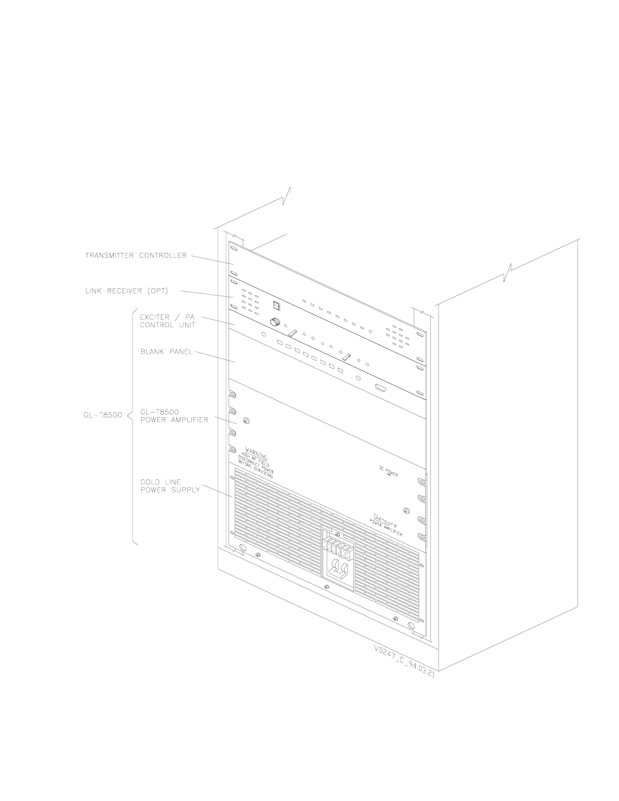
Figure 1-3 GL-T8500 Transmitter (W/C2000) . . . . . . . . . . . . . . . . . . . . 1-5
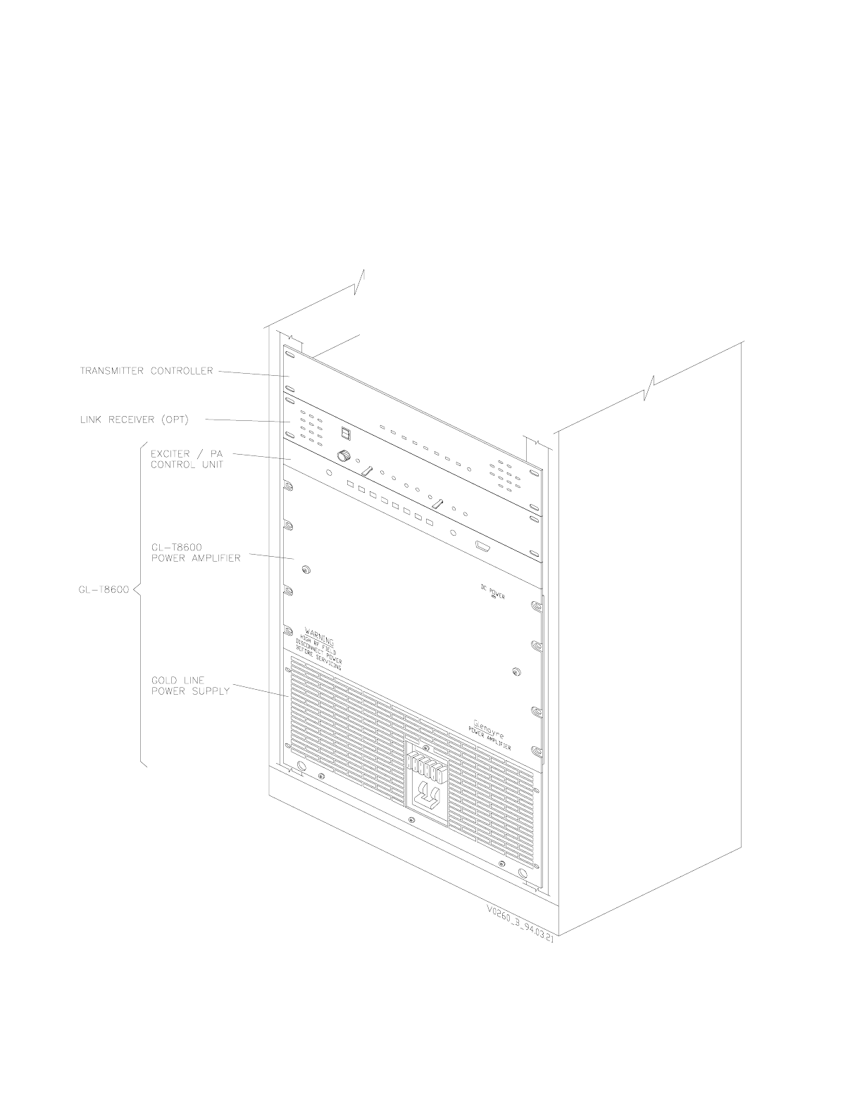
Figure 1-4 GL-T8600 Transmitter (W/C2000) . . . . . . . . . . . . . . . . . . . . 1-6
Figure 3-1 Gold Line GL-T8500 Paging Site Front View Without Receiver . . . . 3-5
Figure 3-2 GL-T8500 Paging Site Back View With Receiver . . . . . . . . . . . . 3-6
Figure 3-3 Gold Line GL-T8600 Paging Site Front View Without Receiver . . . . 3-7
Figure 3-4 Gold Line GL-T8600 Paging Site Back View With Receiver . . . . . . 3-8
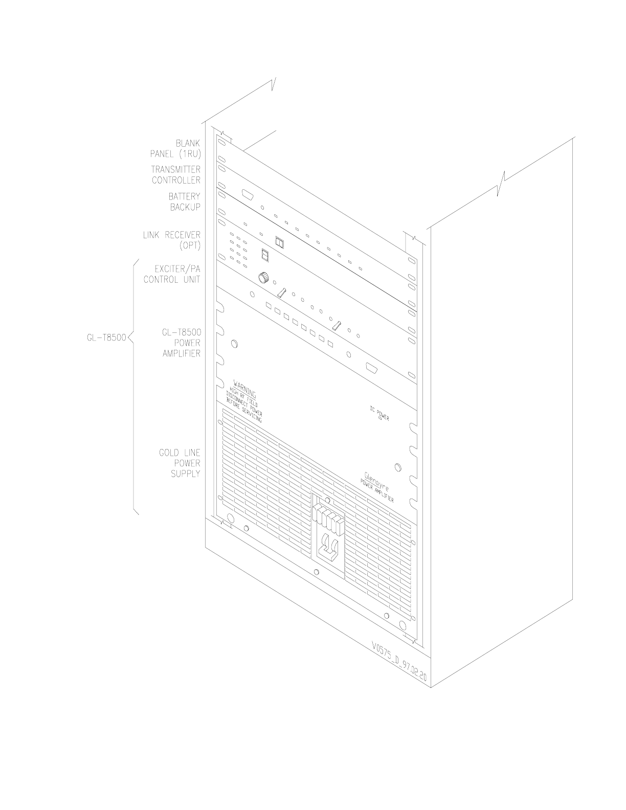
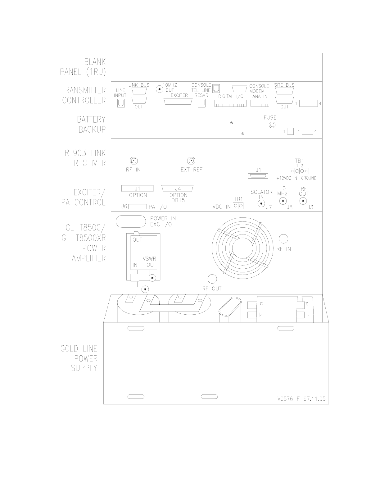
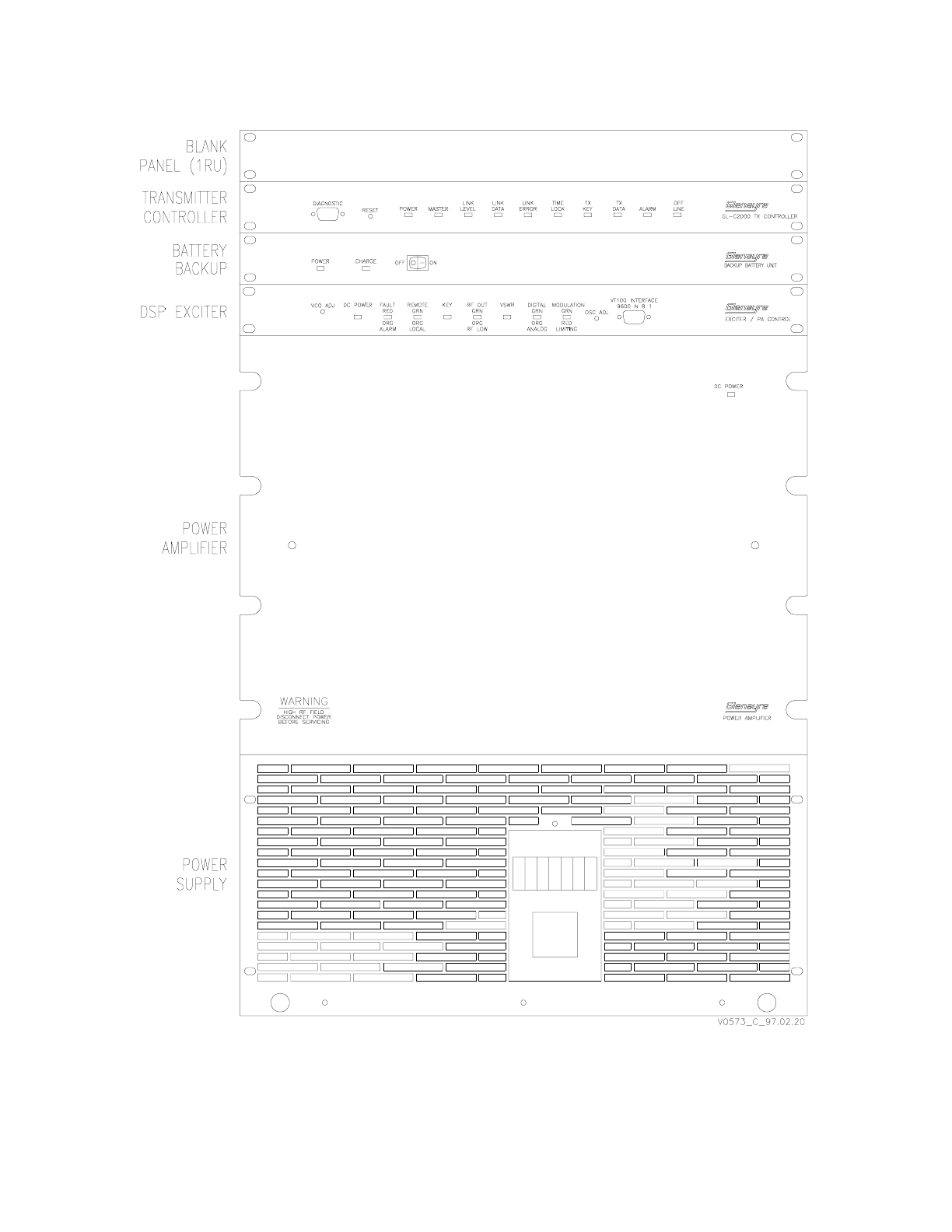
Figure 3-5 GL-T8500 Rackup (w/C2000) . . . . . . . . . . . . . . . . . . . . . . 3-9
Figure 3-6 GL-T8500 Transmitter Back View (w/C2000) . . . . . . . . . . . . . .3-10
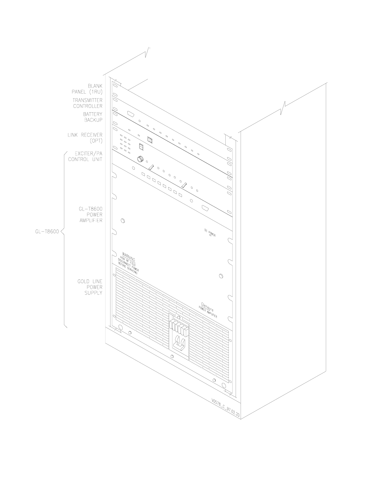
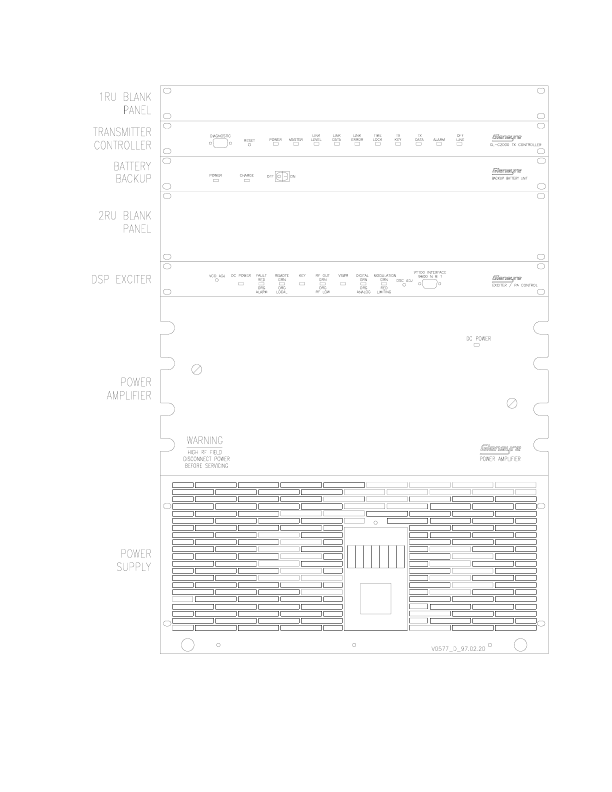
Figure 3-7 GL-T8600 Rackup (w/C2000) . . . . . . . . . . . . . . . . . . . . . .3-11
Figure 3-8 GL-T8600 Transmitter Back View (w/C2000) . . . . . . . . . . . . . .3-12
Figure 3-9 GL-T8500/8600 Simplified Block Diagram . . . . . . . . . . . . . . .3-13
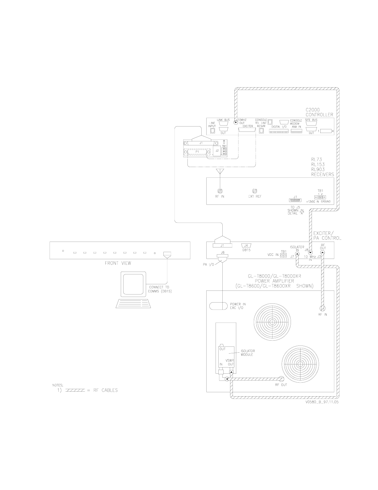
Figure 4-1 Site Installation Diagram . . . . . . . . . . . . . . . . . . . . . . . . . 4-9
Figure 4-2 Site Dc Connection Diagram (w/QT-1000). . . . . . . . . . . . . . . .4-10
Figure 4-3 Site Interconnect Diagram (w/QT-1000) . . . . . . . . . . . . . . . . .4-11
Figure 4-4 Site Dc Connection Diagram (w/C2000) . . . . . . . . . . . . . . . . .4-12
Figure 4-5 Site Interconnect Diagram (w/C2000) . . . . . . . . . . . . . . . . . .4-13
Figure 6-1 Paging Network Signal Diagram (w/QT-1000). . . . . . . . . . . . . . 6-4
Figure 6-2 Paging Network Signal Diagram (w/C2000) . . . . . . . . . . . . . . . 6-5
Figure 6-3 Site Signal-Flow Diagram . . . . . . . . . . . . . . . . . . . . . . . . 6-6
Figure 6-4 Site Signals Diagram (w/QT-1000). . . . . . . . . . . . . . . . . . . . 6-8
Figure 6-5 Site Signal Diagram (w/C2000) . . . . . . . . . . . . . . . . . . . . .6-10

GL-T8500-CN/GL-T8600-CN System Manual Glenayre Document Number: 9110.00163
List of Figures Rev F 11/09/98
Page: vi Copyright © 1998 Glenayre Print Date: 11/09/98

Glenayre Document Number: 9110.00163 GL-T8500-CN/GL-T8600-CN System Manual
Rev F 11/09/98 Table of Contents
sec_1.lot
Print Date: 11/09/98 Copyright © 1998 Glenayre Page: vii
Table of Contents
Table 1-1 Applicable Documents . . . . . . . . . . . . . . . . . . . . . . . . . . 1-1
Table 1-2 Manual Sections . . . . . . . . . . . . . . . . . . . . . . . . . . . . . 1-2
Table 2-1 Specifications . . . . . . . . . . . . . . . . . . . . . . . . . . . . . . . 2-2
Table 3-1 Site Equipment List . . . . . . . . . . . . . . . . . . . . . . . . . . . . 3-2
Table 4-1 Required Tools and Equipment. . . . . . . . . . . . . . . . . . . . . . 4-1
Table 4-2 Power Requirements . . . . . . . . . . . . . . . . . . . . . . . . . . . 4-2
Table 4-3 Equipment Connectors . . . . . . . . . . . . . . . . . . . . . . . . . . 4-4

GL-T8500-CN/GL-T8600-CN System Manual Glenayre Document Number: 9110.00163
Table of Contents Rev F 11/09/98
Page: viii Copyright © 1998 Glenayre Print Date: 11/09/98

Glenayre Document Number: 9110.00163 GL-T8500-CN/GL-T8600-CN System Manual
Rev. F: 11/09/98 GENERAL
sec_1
Print Date: 11/09/98 Copyright © 1998 Glenayre Page: 1-1
1 GENERAL
1.1 Manual Scope
This manual presents the Gold Line GL-T8500 (250W) and GL-T8600 (500W) transmit-
ters, which operate in the 900-MHz range. It includes the QT-1000 interface board with an
interface I/O board. Other paging site equipment is included as listed below.
• transmitter controller
• receiver
• video display terminal (VDT)
• equipment racks
1.2 Applicable Documents
This manual is incomplete without additional manuals. Refer to Table 1-1 for a list of
applicable documents, their part numbers, and a brief description of each.
1.3 Manual Sections
Refer to Table 1-2. This table lists the sections in this manual, and provides a brief descrip-
tion of the content of each section.
Table 1-1 Applicable Documents
document part number description
QT-1000 transmitter
controller manuals IBPHASE3 describes installation, setup, and operation
of QT-1000 control system
GL-T8500/8600 system
manual 9110.00163 this document
GL-T8500/8600 VDT
manual 9110.00164 describes 250/500-W, 900-MHz Gold Line
VDT software operation
exciter / PA control man-
ual 9110.00172 describes exciter/PA control equipment
with interfaces
GL-T8500 power ampli-
fier manual 9110.00160 describes 250-W, 900 MHz Gold Line
power amplifier
GL-T8600 power ampli-
fier manual 9110.00162 describes 500-W, 900 MHz Gold Line
power amplifier
Gold Line power supply
manual 9110.00159 describes 55A/90A Gold Line power
supply equipment

GL-T8500-CN/GL-T8600-CN System Manual Glenayre Document Number: 9110.00163
GENERAL Rev. F: 11/09/98
Page: 1-2 Copyright © 1998 Glenayre Print Date: 11/09/98
1.4 Hardware Identification
Refer to Figure 1-1 and Figure 1-2. These show the GL-T8500 and 8600 transmitters with
a QT-1000 transmitter controller and an RL-903 link receiver, for equipment identification.
Also, refer to Figure 1-3 and Figure 1-4. These show the GL-T8500 and 8600 transmitters
with a C2000 transmitter controller and an RL-903 link receiver, for equipment
identification.
Table 1-2 Manual Sections
section contents
1. General contains scope and content of this entire manual and lists
other applicable documents to supplement this manual
2. Specifications contains overall and selected equipment specifications, and
those not given in other equipment manuals
3. Description contains overall physical and functional equipment descrip-
tions
4. Installation & Setup contains relevant equipment installation information and
setup procedures
5. Site Operation contains overall description of site operation using VDT
menu based commands and procedures
6. Theory of Operation contains overall block-diagram level theory of operation for
equipment listed in paragraph 1.1 above as it functions as a
unit
7. Maintenance contains necessary maintenance procedures which keep site
operating within specified parameters
8. Checkout and Trouble-
shooting contains information needed to checkout and troubleshoot
overall equipment performance
9. Removal and Reinstal-
lation contains information needed to remove and reinstall the rack
and equipment contained in it
Glenayre Document Number: 9110.00163 GL-T8500-CN/GL-T8600-CN System Manual
Rev. F: 11/09/98 GENERAL
sec_1
Print Date: 11/09/98 Copyright © 1998 Glenayre Page: 1-3
Figure 1-1 GL-T8500 Transmitter Isometric Front View
GL-T8500-CN/GL-T8600-CN System Manual Glenayre Document Number: 9110.00163
GENERAL Rev. F: 11/09/98
Page: 1-4 Copyright © 1998 Glenayre Print Date: 11/09/98
Figure 1-2 GL-T8600 Transmitter Isometric Front View
Glenayre Document Number: 9110.00163 GL-T8500-CN/GL-T8600-CN System Manual
Rev. F: 11/09/98 GENERAL
sec_1
Print Date: 11/09/98 Copyright © 1998 Glenayre Page: 1-5
Figure 1-3 GL-T8500 Transmitter (W/C2000)
GL-T8500-CN/GL-T8600-CN System Manual Glenayre Document Number: 9110.00163
GENERAL Rev. F: 11/09/98
Page: 1-6 Copyright © 1998 Glenayre Print Date: 11/09/98
Figure 1-4 GL-T8600 Transmitter (W/C2000)

Glenayre Document Number: 9110.00163 GL-T8500-CN/GL-T8600-CN System Manual
Rev. F: 11/09/98 SPECIFICATIONS
sec_2
Print Date: 11/09/98 Copyright © 1998 Glenayre Page: 2-1
2 SPECIFICATIONS
2.1 Introduction
Specifications given in this section pertain to the equipment described in section three of
this manual. Additional equipment specifications are given in the individual equipment
user manuals. Test and measurement equipment is calibrated in accordance with standards
established by the National Institute of Standards and Technology (NIST).
2.2 Specifications
Refer to Table 2-1.
GL-T8500-CN/GL-T8600-CN System Manual Glenayre Document Number: 9110.00163
SPECIFICATIONS Rev. F: 11/09/98
Page: 2-2 Copyright © 1998 Glenayre Print Date: 11/09/98
Table 2-1 Specifications
characteristic condition specification
Electrical
ac input voltage 50/60 Hz GL-T8500, 120/100 or 220/200 Vac
50/60 Hz GL-T8600, 220/200 Vac
ac input load 120V w/tx keyed GL-T8500, 12-17 A
220V w/tx keyed GL-T8500, 6-10 A
GL-T8600, 12-17 A
dc input voltage see ripple spec 23-28 Vdc, full load-no load
dc input load see ripple spec GL-T8500, 35-50 A @ 25 Vdc
see ripple spec GL-T8600, 70-90 A @ 25 Vdc
dc input ripple up to 120 Hz
over 120 Hz 1.5 Vp-p max
50 mVp-p max
audio input balanced 600 ohm -30 to +10 dBm; refer to exciter manual
RF output continuous duty op-
erating range GL-T8500, 100-300W (sing. circ. out)
GL-T8600, 200-600W (sing. circ. out)
GL-T8600, 200-550W (trip. circ. out)
Physical and Environmental
dimensions 72I cabinet H:W:D 72.6 in: 23 in: 24 in
180 cm: 58 cm: 60 cm
weights 72I cabinet empty approx 210 lb (462 kg)
maximum operating
elevation continuous operation
at rated power 10,000 ft or
3050 m (see temperature derating factor)
temperature range operating
storage -30 to +60 degrees C
-55 to +70 degrees C
temperature derat-
ing factor above 5000 ft or
above 1525 m 2 degrees C per 1000 ft or
2 degrees C per 305 m
humidity operating 0-95 % RH noncondensing
certification FCC identifiers GL-T8500: BFLGL-T8500
GL-T8600: BFLGL-T8600

Glenayre Document Number: 9110.00163 GL-T8500-CN/GL-T8600-CN System Manual
Rev. F: 11/09/98 DESCRIPTION
sec_3
Print Date: 11/10/98 Copyright © 1998 Glenayre Page: 3-1
3 DESCRIPTION
3.1 Introduction
The Gold Line GL-T8500 and GL-T8600 paging site is generally just one of several sites
in the larger paging network. Equipment and options that comprise a particular site may
vary depending on paging system requirements. Paging site operating characteristics are
determined by hardware options and controlling software features.
Note the distinction between the paging site and the paging transmitter. A GL-T8500 or
GL-T8600 paging site consists of a Gold Line paging transmitter, a receiver (non-wireline
applications), and a transmitter controller. A paging transmitter consists of an exciter, a
power amplifier, and a power supply. The receiver and transmitter controller provide
support functions for the paging transmitter which allows it to function as a part of a larger
paging network.
The purpose of a paging transmitter is to modulate a specific RF carrier channel with
paging information and amplify it for broadcast. The paging transmitter cannot function in
a paging network without the other site equipment. The purpose of a paging site is to
broadcast paging information on a specific channel (frequency) at a specific time. Paging
site equipment is racked together for practical and functional reasons. The paging site
broadcasts paging information in response to commands from the paging terminal. All of
the paging site equipment is usually part of a larger paging network, which is typically
comprised of several paging sites.
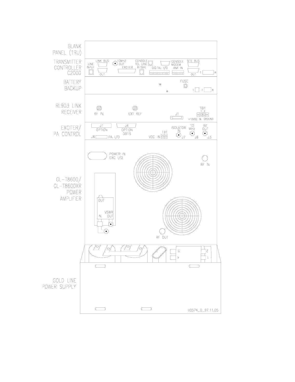
3.2 Physical Description
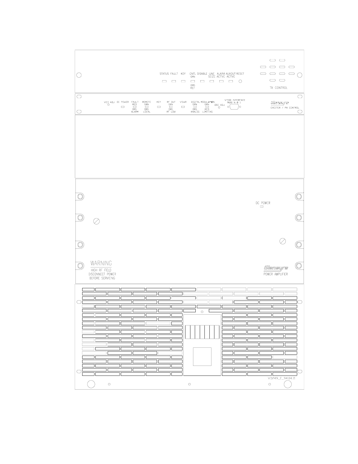
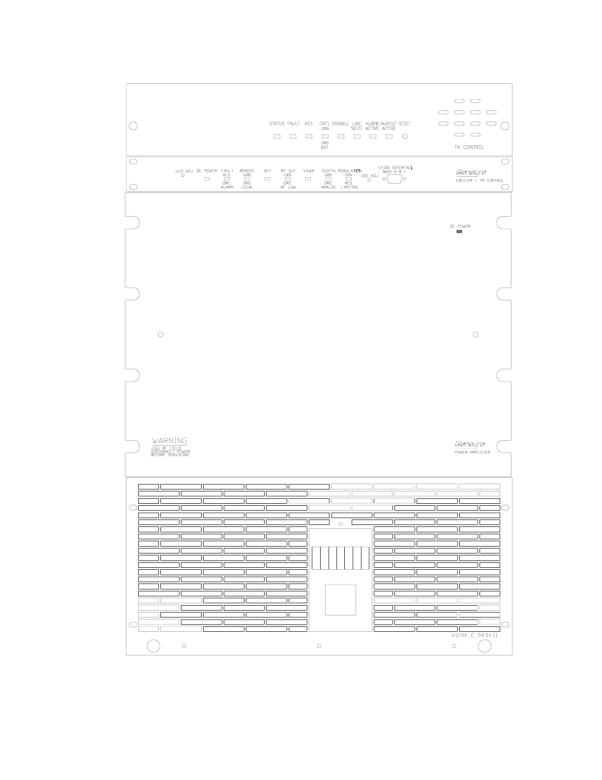
Refer to Figure 3-1 and Figure 3-2, for equipment names, identifying features, and
equipment racking order. Refer to Table 3-1, for equipment part numbers, and brief descrip-
tions. Refer to Figure 3-3 and Figure 3-4, for connector names and locations. Refer to the
individual equipment user manuals for more information.
Refer to Figure 3-5, Figure 3-6, Figure 3-7, and Figure 3-8. These provide similar infor-
mation as those listed above but feature the C2000 transmitter controller.

GL-T8500-CN/GL-T8600-CN System Manual Glenayre Document Number: 9110.00163
DESCRIPTION Rev. F: 11/09/98
Page: 3-2 Copyright © 1998 Glenayre Print Date: 11/10/98
.
3.2.1 Exciter / PA Control Unit
The Gold Line exciter/ PA control unit is one rack unit high. It is racked where shown and
is held in place with four machine screws. The top cover is removable for access to subas-
semblies, jumpers, and adjustments contained in the unit. All but one of its connectors are
on the back of the unit. The front of this unit has a connector which allows the VDT to be
connected to it.
3.2.2 Power Amplifier (PA)
The Gold Line PA is normally installed above the power supply and is held in place with
several machine screws. By removing the front cover, internal components and subassem-
blies can be accessed without removing the PA from the rack. All PA I/O connections are
made from the back. Each power amplifier is equipped with an RF circulator mounted on
the PA heatsink.
3.2.3 Power Supply
The Gold Line power supply is supported by a shelf that is mounted to the bottom of the
rack and is held in place by several machine screws along the bottom front. The perf panel
on the supply front is for cooling ventilation; do not obstruct it. Some components can be
accessed by removing the perf panel; to access others, the supply must be removed from
the rack. All interconnections are made at the back where the connectors are accessible. A
connector-ended cable inside the supply allows quick disconnection from the equipment
rack wiring harness.
Table 3-1 Site Equipment List
equipment part number function
power supply
55 A version
90 A version 265-0082-012
265-0082-006
provides dc to site equipment
power amplifier
GL-T8500
GL-T8600 265-0082-013
265-0082-005
amplifies 900 MHz RF for broadcast
exciter/PA
control unit refer to exciter manual generates then modulates RF; controls PA
I/O activities
link receiver
(RL-903) 265-00301-xxx, see re-
ceiver manual for con-
figurations & part No.
receives data and commands from the
system controller
transmitter
controller controls paging transmitter activities;
performs I/O functions for paging site

Glenayre Document Number: 9110.00163 GL-T8500-CN/GL-T8600-CN System Manual
Rev. F: 11/09/98 DESCRIPTION
sec_3
Print Date: 11/10/98 Copyright © 1998 Glenayre Page: 3-3
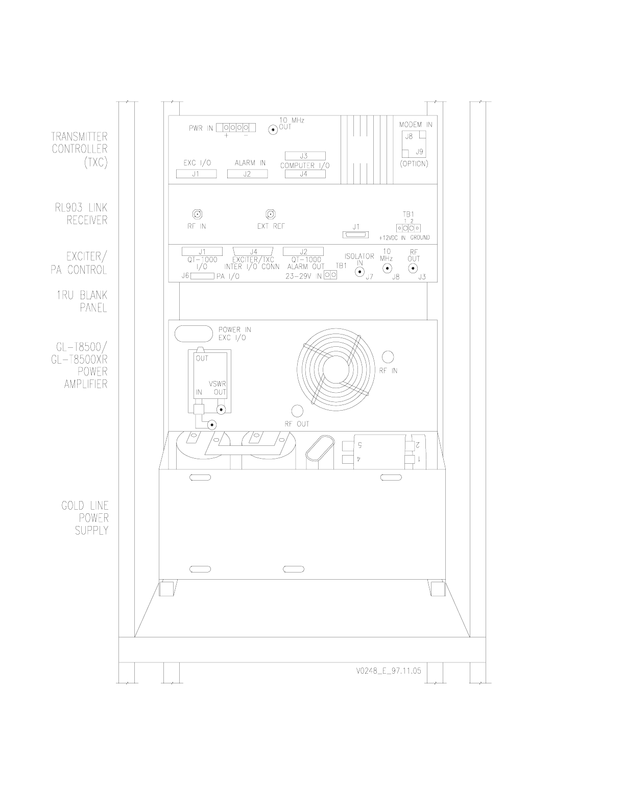
3.2.4 Transmitter Controller
The transmitter controller is normally racked at the top. A controller may or may not be
mounted to the rack with slide rails. By loosening the two thumbscrews on the front of the
TXC, the controller slides forward from the rack. By loosening the four top cover thumb-
screws, the top can be removed for access to the subassemblies, jumpers, indicators, and
adjustments contained in the unit. On the back of the transmitter controller are a variety of
connectors which are not all used for any one particular application. When using a QT1000
controller, do not rely on identifiers which are molded in the back of the TXC; use the appli-
cable figures provided in this manual.
3.2.5 Link Receiver
3.2.5.1 RL-903
The receiver is racked below the transmitter controller. By loosening the top cover screws,
the top can be removed for access to the subassemblies, jumpers, and adjustments
contained in the unit. All interconnections to other site equipment are made to connectors
on the back of the receiver. Refer to the receiver user manual for more information.
3.2.6 Video Display Terminal (VDT)
The VDT is required for setup, local control, and monitoring of the Gold Line transmitter.
It is also required for local interrogation of the transmitter controller. The VDT can be any
compatible laptop or desktop computer running a VT-100 emulation program. The VDT
has a brightness and contrast control to accommodate various lighting conditions and
probably has its own power conversion and supply system.
3.2.7 Rack Cabinet
An air plenum covers the back of the power amplifier when the transmitter is installed in a
72-inch rack cabinet; this provides improved cooling. Connectors are accessible with the
air plenum removed.
3.3 Simplified Functional Description
3.3.1 Paging Site
Refer to Figure 3-9, for a block-diagram representation of the paging site equipment.
The paging site receives paging and command information from equipment outside the
paging site through telephone land lines or a link receiver. Incoming information is decoded
by the transmitter controller and sent to the exciter / PA control unit, which uses a micro-
processor to translate received information into useful paging functions. The exciter / PA
control unit generates modulated RF and control signals which are sent to the power ampli-
fier. The PA amplifies and broadcasts the modulated RF .

GL-T8500-CN/GL-T8600-CN System Manual Glenayre Document Number: 9110.00163
DESCRIPTION Rev. F: 11/09/98
Page: 3-4 Copyright © 1998 Glenayre Print Date: 11/10/98
The purpose of the exciter/PA control unit is twofold. The exciter section generates a
modulated RF carrier which is applied to the input of the PA. The PA control section
controls and monitors the PA using a microprocessor based system.
3.3.2 Paging Site Control
The Gold Line paging transmitter has divided control functions. Since the power amplifier
has no internal control circuitry, the exciter / PA control unit sends commands to the PA and
receives status information from the PA.
3.3.3 Link Receiver
The link receiver connects the paging site equipment to the off-site paging equipment when
telephone land lines are not used. It receives paging data and commands and forwards that
information to the transmitter controller.
3.3.4 Video Display Terminal
The VDT interfaces the transmitter through the connector on the front of the exciter. Refer
to the VT-100 VDT user manual for screen display details.
3.3.5 Interface I/O Board
The interface board is mounted to the rear of the exciter / PA control unit with four machine
screws. The terminal board and D-sub connector on the interface I/O board provide
identical electrical interface through different physical configurations. Refer to the exciter
/ PA control unit user manual for more information.
Glenayre Document Number: 9110.00163 GL-T8500-CN/GL-T8600-CN System Manual
Rev. F: 11/09/98 DESCRIPTION
sec_3
Print Date: 11/10/98 Copyright © 1998 Glenayre Page: 3-5
Figure 3-1 Gold Line GL-T8500 Paging Site Front View Without Receiver
GL-T8500-CN/GL-T8600-CN System Manual Glenayre Document Number: 9110.00163
DESCRIPTION Rev. F: 11/09/98
Page: 3-6 Copyright © 1998 Glenayre Print Date: 11/10/98
Figure 3-2 GL-T8500 Paging Site Back View With Receiver
Glenayre Document Number: 9110.00163 GL-T8500-CN/GL-T8600-CN System Manual
Rev. F: 11/09/98 DESCRIPTION
sec_3
Print Date: 11/10/98 Copyright © 1998 Glenayre Page: 3-7
Figure 3-3 Gold Line GL-T8600 Paging Site Front View Without Receiver
GL-T8500-CN/GL-T8600-CN System Manual Glenayre Document Number: 9110.00163
DESCRIPTION Rev. F: 11/09/98
Page: 3-8 Copyright © 1998 Glenayre Print Date: 11/10/98
Figure 3-4 Gold Line GL-T8600 Paging Site Back View With Receiver
Glenayre Document Number: 9110.00163 GL-T8500-CN/GL-T8600-CN System Manual
Rev. F: 11/09/98 DESCRIPTION
sec_3
Print Date: 11/10/98 Copyright © 1998 Glenayre Page: 3-9
Figure 3-5 GL-T8500 Rackup (w/C2000)
GL-T8500-CN/GL-T8600-CN System Manual Glenayre Document Number: 9110.00163
DESCRIPTION Rev. F: 11/09/98
Page: 3-10 Copyright © 1998 Glenayre Print Date: 11/10/98
Figure 3-6 GL-T8500 Transmitter Back View (w/C2000)
Glenayre Document Number: 9110.00163 GL-T8500-CN/GL-T8600-CN System Manual
Rev. F: 11/09/98 DESCRIPTION
sec_3
Print Date: 11/10/98 Copyright © 1998 Glenayre Page: 3-11
Figure 3-7 GL-T8600 Rackup (w/C2000)
GL-T8500-CN/GL-T8600-CN System Manual Glenayre Document Number: 9110.00163
DESCRIPTION Rev. F: 11/09/98
Page: 3-12 Copyright © 1998 Glenayre Print Date: 11/10/98
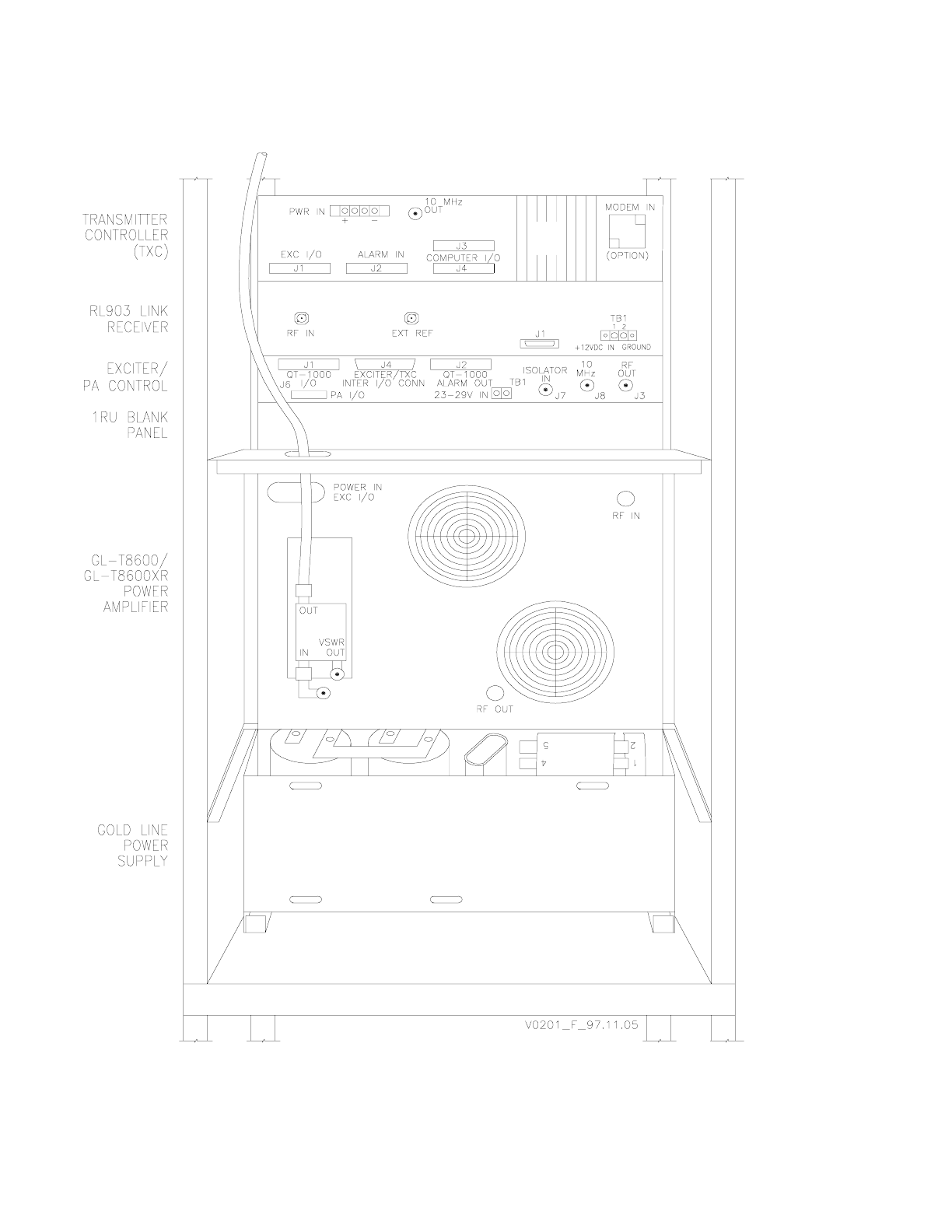
Figure 3-8 GL-T8600 Transmitter Back View (w/C2000)
Glenayre Document Number: 9110.00163 GL-T8500-CN/GL-T8600-CN System Manual
Rev. F: 11/09/98 DESCRIPTION
sec_3
Print Date: 11/10/98 Copyright © 1998 Glenayre Page: 3-13
Figure 3-9 GL-T8500/8600 and GL-T8500/8600-CN Simplified Block Diagrams

GL-T8500-CN/GL-T8600-CN System Manual Glenayre Document Number: 9110.00163
DESCRIPTION Rev. F: 11/09/98
Page: 3-14 Copyright © 1998 Glenayre Print Date: 11/10/98

Glenayre Document Number: 9110.00163 GL-T8500-CN/GL-T8600-CN System Manual
Rev. F: 11/09/98 INSTALLATION AND SETUP
sec_4
Print Date: 11/09/98 Copyright © 1998 Glenayre Page: 4-1
4 INSTALLATION AND SETUP
4.1 Installation
Refer to Figure 4-1, for general information.
4.1.1 Tools and Equipment Required
Refer to Table 4-1. Equipment listed by brand name may be substituted with equivalent.
For installation, only common hand tools are necessary if at all, since installation is usually
completed at the factory.
4.1.2 Rack Positioning
Rackup variations are generally not possible. Cooling and cabling restraints require that
equipment pieces remain racked as shown. Detailed descriptions of equipment mounting
and installation procedures are given in the various equipment user manuals.
During normal operation the equipment rack can be placed with its back or top close to
another object since it ventilates through the front and sides. However, to gain reasonable
access to the front or back for maintenance purposes, 30 inches of free space should be
allowed. For ventilation, the front of the rack should have at least ten inches of free space,
and seven inches should be allowed for each side. The cabinet should be placed as close as
possible to the transmitting antenna, and to the primary power source as a secondary
consideration.
Caution
Never place the rack where moisture, steam,
condensation, or standing water, can come in
contact with it. The host room may need to be air
conditioned or additionally ventilated to remove
excess heat generated by this equipment.
Table 4-1 Required Tools and Equipment
nut driver - 5/16”
screw driver - # 3 flat blade
screw driver - #3 Phillips
Bird 4421 RF power meter
Bird 8327 dummy load
barrel connector - type-N
cable - 1 M long (max) with type-N ends
Fluke 77 DVM

GL-T8500-CN/GL-T8600-CN System Manual Glenayre Document Number: 9110.00163
INSTALLATION AND SETUP Rev. F: 11/09/98
Page: 4-2 Copyright © 1998 Glenayre Print Date: 11/09/98
4.1.3 Rack Grounding
The rack cabinet must be connected to a reliable earth ground. Connect the earth ground
point to the ground stud provided in the bottom of the cabinet; use four gauge or larger
copper conductor.
4.1.4 Inspection
Inspect the equipment to be certain that the equipment rack is complete. Compare items
received to the packing list. Report shipping loss or damage to carrier within 15 days of
receipt. Remove any packing material from the rack and check each assembly. Pay partic-
ular attention to the power supply; check it closely and remove any foreign material in the
chassis. Be certain to disconnect primary power from the power supply before removing
any equipment covers.
4.1.5 Primary Power Requirements
The primary power source must be capable of delivering adequate power to the equipment.
Refer to Table 4-2. This equipment operates with 60 Hz ac unless the power supply has the
50 Hz option or the dc only option installed. Refer to section 2 of this manual for current
and voltage specifications. Electrical connections made to this equipment must be made in
accordance with local electrical codes.
4.1.5.1 Special Considerations
Various options for the G/L power supply permit operation at different line frequencies and
voltages. The supplied connector allows for these variations. If the supplied connector is
not used, be certain that the correct combination of line frequency and voltage is applied.
The G/L power supply causes a large inrush of current when first turned on. The ac supply
breaker must be able to handle this brief surge.
Table 4-2 Power Requirements
input type transmitter power
required wire size
ac 50/60 Hz GL-T8500 2200 W max 12 gauge
ac 50/60 Hz GL-T8600 3740 W max 12 gauge
dc only GL-T8500 2000 W max 0 gauge
dc only GL-T8600 3540 W max 0 gauge

Glenayre Document Number: 9110.00163 GL-T8500-CN/GL-T8600-CN System Manual
Rev. F: 11/09/98 INSTALLATION AND SETUP
sec_4
Print Date: 11/09/98 Copyright © 1998 Glenayre Page: 4-3
4.1.6 Equipment Cabling
4.1.6.1 Ac Connections
The ac input cable comes fitted with a three-pronged ac connector. A grommeted hole in
the cabinet is recommended for cable throughput. A three-terminal connector block is
mounted inside the air plenum; the power supply input cable is also connected here. The ac
input is fused at CB1 on the front of the power supply. All ac connections internal to the
rack are made at the factory and should not need to be modified.
4.1.6.2 Dc Connections
Refer to Figure 4-2 and Figure 4-4 for more information. This figure shows a GL-T8600
transmitter; connections are the same for the GL-T8500 transmitter.
4.1.6.3 I/O Connections
Refer to Figure 4-3 and Figure 4-5 for more information. This figure shows a GL-T8600
transmitter; connections are the same for the GL-T8500 transmitter.
4.1.7 Dc Only Sites
Some installation do not use ac input power. Usually it is racked and wired at the factory,
but it can be retrofitted. Be sure to connect as shown in the dc only power supply user
manual.
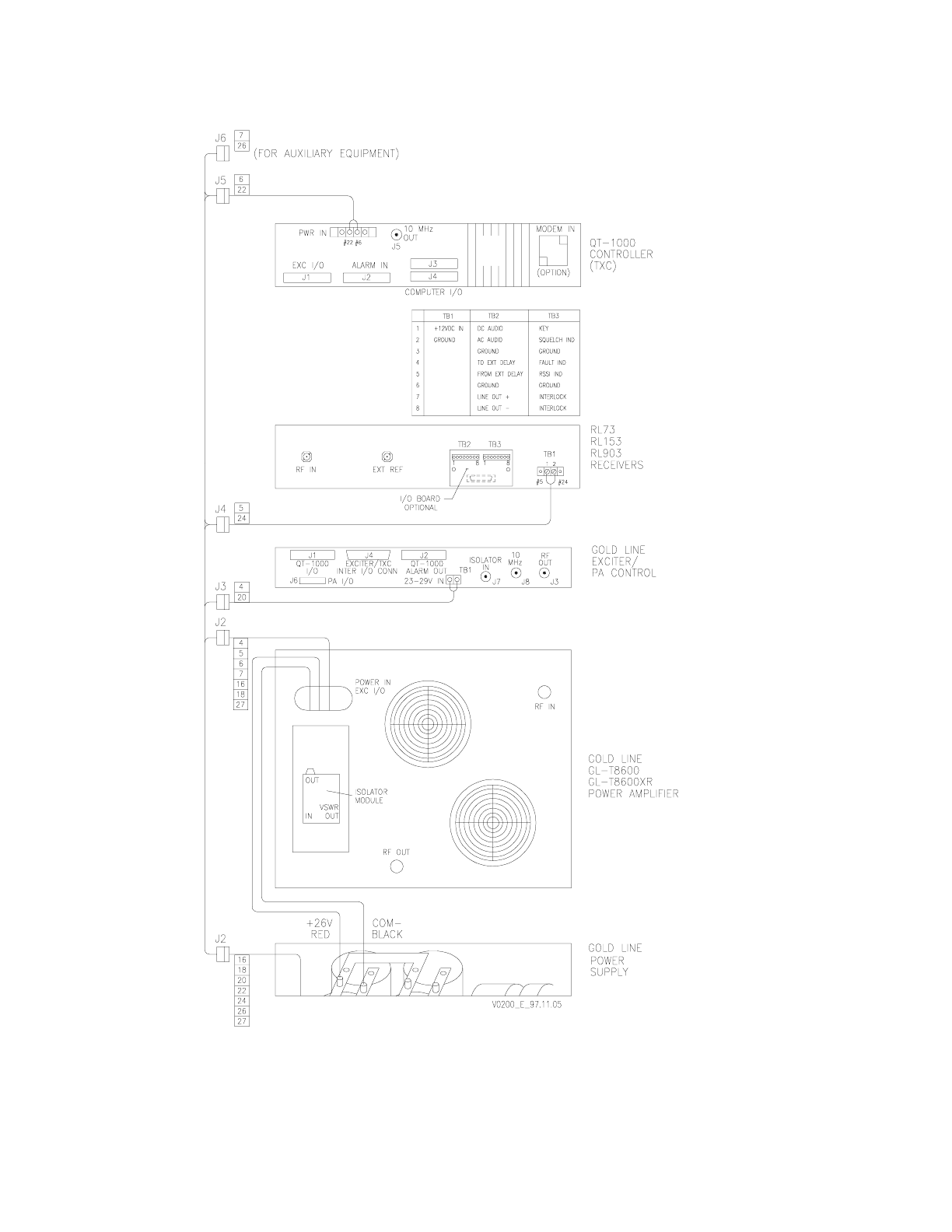
4.1.8 System Connectors
Refer to Table 4-3. This table lists connectors by equipment unit. Connections made to
equipment outside the cabinet are also described below.
To the isolator, connect the transmit antenna coax cable to OUT. Some installations may
also include a lightning protection device between the isolator and antenna. The connector
is typically a type-N and should be securely tightened.
To the receiver (if used), connect the receive antenna coax cable at RF IN. The connector
is typically type-N and should be securely tightened. Some installations include a lightning
protection device between the receiver and antenna.
If used, connect the telephone wireline to the TXC at MODEM IN. Modem specifications
are given in the TXC user manual.

GL-T8500-CN/GL-T8600-CN System Manual Glenayre Document Number: 9110.00163
INSTALLATION AND SETUP Rev. F: 11/09/98
Page: 4-4 Copyright © 1998 Glenayre Print Date: 11/09/98
Note: In the table below, the > symbol is short for “is connected to”.
4.2 Setup
4.2.1 Introduction
This subsection contains setup procedures for the Gold Line transmitter with a TXC. These
procedures are usually performed only once, when the transmitter is initially installed at the
site. This procedure presumes that the equipment has already been factory configured for
the correct RF band, transmitter controller, and oscillator. Refer to the VDT user manual
for more information on these and other procedures.
4.2.2 Setup Procedures
The procedure is divided into separate areas for activation, password setup, channel setup,
digital mode setup, analog mode setup, forward power setup, oscillator calibration, and
preoperational check. Perform each in the order shown. Setup procedures include the
following:
Table 4-3 Equipment Connectors
equipment connector destination
TXC J1 >exc J1:
J2 >exc J2:
J3 not used
J4 > VDT:
J5 > exc J8:
J8/9 > telephone land line:
RX rf in > antenna:
ext ref >
J1 > exc J5 (interface I/O bd):
PA exc io > exc J6:
rf in > exc J3:
rf out > isolator in:
vswr out > exc J7:
iso out > antenna:
EXC connectors listed above not repeated under EXC
J4 > interface i/o bd:
TB2 > (see exc IB):
VT100 > VDT:

Glenayre Document Number: 9110.00163 GL-T8500-CN/GL-T8600-CN System Manual
Rev. F: 11/09/98 INSTALLATION AND SETUP
sec_4
Print Date: 11/09/98 Copyright © 1998 Glenayre Page: 4-5
• equipment power-up
• starting VDT software
•password setup
• channel setup
• forward power setup
• preoperational checks
• paging check
4.2.2.1 Equipment Power-Up
Operating power for racked equipment is regulated by the power supply in the bottom of
the rack. Operating power for the VDT is independent of the power supply.
Transmitter power-up is accomplished by setting the breaker switch on the supply front to
the up position. Also, on the receiver, set front panel switch to on position.VDT power-up
is accomplished by setting the its power switch to the on position. Be sure VDT is properly
connected to primary power.
4.2.2.2 Starting VDT Software (QT-1000 only)
Once the VDT is powered, one of two programs must be running to facilitate communica-
tions with site hardware. This procedure presumes that the proper programs are already
loaded into the computer console. The VDT interacts with the G/L transmitter when the
‘VT-100’ console program runs. The VDT interacts with the QT-1000 controller (TXC)
when the ‘DOS’ console program runs.
Starting the VT-100 console is accomplished by performing the steps in the list below.
• Type 'cd procomm' and enter it.
• Type 'procomm' and enter it.
• As instructed by the VDT, press a key to begin.
• Enter ‘local’ control mode to prevent any remote control interference.
The VT-100 program should now be running. For detailed instructions on operating this
program software, refer to the VDT user manual.
Starting DOS console is accomplished by performing steps in list below.
• Type 'cd console' and enter it.
• Type 'console' and enter it.
• As instructed by the VDT, press a key to begin.
• If necessary, type 'quintron' and enter it at the password query.
• Enter ‘local’ control mode to prevent any remote control interference.
The QT-1000 console program should now be running. For detailed instructions on
operating this program software, refer to the TXC user manual.

GL-T8500-CN/GL-T8600-CN System Manual Glenayre Document Number: 9110.00163
INSTALLATION AND SETUP Rev. F: 11/09/98
Page: 4-6 Copyright © 1998 Glenayre Print Date: 11/09/98
4.2.2.3 Password Setup
To prevent unauthorized tampering, change both frequency and entry passwords. An entry
password should be used in both VT-100 and DOS console programs.
Initiating a password in the DOS console program is accomplished by performing the steps
in the list below.
• Start the DOS console program. (see above).
• Enter ‘console setup’ menu.
• Enter ‘edit passwords’ submenu.
For more details, refer to manual 9110.00028.
Initializing a password in the VT-100 console program is accomplished by performing the
steps in the list below.
• Start the VT-100 console program. (see above).
• When the password query appears, enter ‘abcd’.
• Enter ‘local’ main menu..
• Enter ‘change tx settings’ menu item..
• Enter ‘change frequency password’ submenu. OR
• Enter ‘change / toggle entry password’ submenu.
The VT-100 VDT uses two passwords to provide a higher level of security for entry into
the transmitter channel frequency change area. For more details, refer to the VT-100 user
manual.
4.2.2.4 Channel Setup
On site channel setup is not required if the transmitter was configured at the factory.
Generally all transmitters are setup at the factory. This procedure presumes that the trans-
mitter status has already been checked and the procedure needs to be performed.
Channel setup (frequency settings) is accomplished by performing the steps in the list
below.
• Start the VT-100 console program. (see above).
• Enter ‘local’ main menu.
• Enter ‘change tx settings’ menu item.
• Enter ‘set frequencies’ submenu. This requires password entry.
• Follow screen prompts as given.
For more details, refer to the VT-100 screen displays manual.

Glenayre Document Number: 9110.00163 GL-T8500-CN/GL-T8600-CN System Manual
Rev. F: 11/09/98 INSTALLATION AND SETUP
sec_4
Print Date: 11/09/98 Copyright © 1998 Glenayre Page: 4-7
4.2.2.5 Forward Power Setup
The forward power setup procedures are necessary for all transmitter installations. Proce-
dures include: forward power calibration, forward power adjustment, and alarm level
setting. Before starting, select mode and channel in which the transmitter is to operate.
Forward power calibration is accomplished by performing the ‘forward power calibration
procedure’ given in the MAINTENANCE section of this manual. Refer to that section for
details. Since most transmitters have already been calibrated at the factory and should not
be recalibrated, check calibration status by performing the steps listed below.
• Start the VT-100 console program. (see above).
• Enter ‘local’ main menu.
• Enter ‘view tx status’.
• Enter ‘view faults selection’ submenu. If ‘fwd calib’ is OK, do not do forward power
calibration. If a fault exists, do procedure as described above.
Follow screen prompts as shown.
Forward power adjustment is accomplished by performing the steps in the list below.
• Start the VT-100 console program. (see above).
• Enter ‘local’ main menu.
• Enter ‘change tx settings’.
• Enter ‘adj fwd pwr’ submenu.
Follow screen prompts as shown.
Set power output level to rated transmitter output unless diminished coverage area is
desired.
Alarm level setting is accomplished by performing the steps in the list below.
• Start the VT-100 console program. (see above).
• Enter ‘local’ main menu.
• Enter ‘change tx settings’.
• Enter ‘set low pwr alarm’ submenu.
Follow screen prompts as shown.
4.2.2.6 Preoperational Checks
These checks should be performed before the transmitter is put into paging service.
Transmitter check is accomplished by performing the steps in the list below.
• Start the VT-100 console program. (see above).
• Enter ‘local’ main menu.
• Enter ‘view tx status’.

GL-T8500-CN/GL-T8600-CN System Manual Glenayre Document Number: 9110.00163
INSTALLATION AND SETUP Rev. F: 11/09/98
Page: 4-8 Copyright © 1998 Glenayre Print Date: 11/09/98
• Enter ‘view faults selection’ submenu.
• Key transmitter; verify that no faults exist.
Follow screen prompts as shown.
Exciter LED check is accomplished by performing the ‘exciter LED self-test’; refer to VDT
user manual. Verify that all conditions are OK.
4.2.2.7 Paging Check
Paging check is accomplished by performing the steps in the list below. This check should
be performed using at least three pagers. Pagers should be tuned to every on-frequency and
every adjacent frequency.
• Start the VT-100 console program. (see above).
• Enter ‘remote’ main menu.
• Set transmitter mode and channel as required.
• Send page and verify appropriate pager response; repeat for each operating frequency.
• Send page and verify that adjacent channel pagers do not respond; repeat for each
adjacent frequency.
The transmitter setup procedures are completed. Refer to the VDT user manual for more
information on checkout procedures.
Glenayre Document Number: 9110.00163 GL-T8500-CN/GL-T8600-CN System Manual
Rev. F: 11/09/98 INSTALLATION AND SETUP
sec_4
Print Date: 11/09/98 Copyright © 1998 Glenayre Page: 4-9
Figure 4-1 Site Installation Diagram
GL-T8500-CN/GL-T8600-CN System Manual Glenayre Document Number: 9110.00163
INSTALLATION AND SETUP Rev. F: 11/09/98
Page: 4-10 Copyright © 1998 Glenayre Print Date: 11/09/98
Figure 4-2 Site Dc Connection Diagram (w/QT-1000)
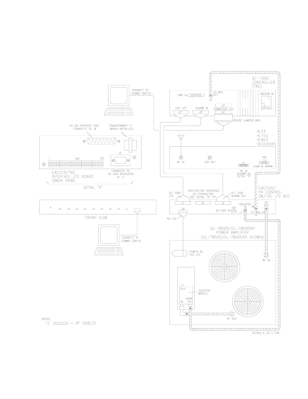
Glenayre Document Number: 9110.00163 GL-T8500-CN/GL-T8600-CN System Manual
Rev. F: 11/09/98 INSTALLATION AND SETUP
sec_4
Print Date: 11/09/98 Copyright © 1998 Glenayre Page: 4-11
Figure 4-3 Site Interconnect Diagram (w/QT-1000)
GL-T8500-CN/GL-T8600-CN System Manual Glenayre Document Number: 9110.00163
INSTALLATION AND SETUP Rev. F: 11/09/98
Page: 4-12 Copyright © 1998 Glenayre Print Date: 11/09/98
Figure 4-4 Site Dc Connection Diagram (w/C2000)
Glenayre Document Number: 9110.00163 GL-T8500-CN/GL-T8600-CN System Manual
Rev. F: 11/09/98 INSTALLATION AND SETUP
sec_4
Print Date: 11/09/98 Copyright © 1998 Glenayre Page: 4-13
Figure 4-5 Site Interconnect Diagram (w/C2000)

GL-T8500-CN/GL-T8600-CN System Manual Glenayre Document Number: 9110.00163
INSTALLATION AND SETUP Rev. F: 11/09/98
Page: 4-14 Copyright © 1998 Glenayre Print Date: 11/09/98

Glenayre Document Number: 9110.00163 GL-T8500-CN/GL-T8600-CN System Manual
Rev. F: 11/09/98 OPERATION
sec_5
Print Date: 11/09/98 Copyright © 1998 Glenayre Page: 5-1
5 OPERATION
5.1 Introduction
Normally this equipment is operated remotely from the paging terminal. When the trans-
mitter is in the local operating mode. Only very limited operation can be done with front-
panel controls. Front panels controls and indicators are presented below. Refer to the indi-
vidual equipment user manuals for more detailed information.
5.1.1 Precautions and Hazards
WARNING
It is unsafe and counterproductive to operate this
equipment when covers are removed. Remove ac
and dc power before making modifications to any
equipment. Avoid the PA if it is keyed and the PA
front cover is removed. Do not disconnect any RF
connectors while the PA is keyed. During
operation, the lower section of the power supply
front panel gets very hot; do not touch it.
5.2 Local Operation
The Gold Line transmitter is operated using the video display terminal (VDT), which runs
a DEC VT-100 emulating program e.g., ProComm. Refer to the VDT user manual for more
information about local operation using the VDT.
5.3 Front Panels Controls and Indicators
5.3.1 Exciter/PA Control Unit
The front panel contains the controls and indicators listed below.
• VCO ADJ - potentiometer adjusts VCO frequency fine tuning
• DC POWER - LED either not lighted or lights green; green is normal
• FAULT/ALARM - LED lights red or orange; neither is normal
• REMOTE/LOCAL - LED lights green or orange; green is normal
• KEY - LED either not lighted or lights green; either can be normal
• RF OUT/RF LOW - LED lights green or orange; green is normal
• VSWR - LED either not lighted or lights red; not lighted is normal
• DIGITAL/ANALOG - LED lights green or orange; either is normal
• MODULATION/LIMITING - LED lights green or red; green is normal

GL-T8500-CN/GL-T8600-CN System Manual Glenayre Document Number: 9110.00163
OPERATION Rev. F: 11/09/98
Page: 5-2 Copyright © 1998 Glenayre Print Date: 11/09/98
5.3.2 Power Amplifier (PA)
The power amplifier has no controls; the only front panel indicator is listed below.
• DC POWER - not lighted or lighted green; green is normal
5.3.3 Power Supply
The power supply has one control and several fuses listed below.
• no stencil - circuit breaker switch for primary power to power supply
• +13.5V 5A - fuse for 13.5 volt supply to PA metering board
• FAN1 3A - fuse for PA cooling fan one
• FAN2 3A - fuse for PA cooling fan two (GL-T8600 PA only)
• EXC 5A - fuse for exciter/PA control unit
• CNTL 5A - fuse for transmitter controller
• RX 3A - fuse for link receiver
• AUX 3A - fuse for other auxiliary equipment
5.3.4 Transmitter Controller
The front panel contains one control and the indicators listed below.
• STATUS - LED blinks green or is not lighted; blinking is normal
• FAULT - LED lights red or is not lighted; not lighted is normal
• KEY - LED lights green momentarily or is not lighted; either is normal
• CNTL/REF - LED lights green or orange momentarily; either is OK
• DISABLE - LED lights red momentarily; not lighted is normal
• LINE SEIZE - LED lights orange momentarily; refer to user manual
• ALARM ACTIVE - LED lights red; not lighted is normal
• AUXOUT ACTIVE - LED lights orange; refer to user manual
• RESET - switch resets the transmitter controller
5.3.5 Link Receiver
The front panel contains the controls and indicators listed below.
• no stencil - off/on switch controls power to unit
• VOLUME - adjusts monitor speaker volume
• POWER - LED is normally lighted
• NORMAL/TEST/TIGHT - switch that sets receiver squelch mode
• NORMAL - LED lights when receiver squelch in normal
• TIGHT - LED lights when receiver squelch set to tight

Glenayre Document Number: 9110.00163 GL-T8500-CN/GL-T8600-CN System Manual
Rev. F: 11/09/98 OPERATION
sec_5
Print Date: 11/09/98 Copyright © 1998 Glenayre Page: 5-3
• LINE OUT - adjustment for line out level
• OK/HI - LED lights green or red to show line out level; green is normal
• KEY/DIS/REMOTE - switch sets receiver key mode; remote is normal
• KEY LINE - LED is lighted when transmitter is keyed
• FAULT - LED lights red for VCO fault; not lighted is normal
5.4 Front-Panel Operations
The following subparagraphs present operations that are accomplished using front-panel
controls. Since this is a computer-controlled transmitter, only the operations listed below
are possible without the VDT.
• resetting transmitter controller
• receiver power control
• receiver audio monitoring level
• receiver squelch setting
• receiver key options setting
5.4.1 Resetting the Transmitter Controller
To reset the transmitter controller, push the recessed RESET switch. This action re-boots
the controller. It is used only when the controller is nonresponsive to system or user
commands. Reset can cause a loss or change of site operating parameters. Refer to the
transmitter controller user manual for all details.
5.4.2 Receiver Power Control
To apply power to the receiver, set the 1/0 switch to 1; to turn unit off, set switch to 0.
5.4.3 Receiver Audio Monitoring Level
To increase receiver audio monitoring level, turn VOLUME control clockwise. To decrease
level, turn it counterclockwise.
5.4.4 Receiver Squelch Setting
To put receiver in squelch mode, set SQUELCH switch to NORMAL. To put unit in carrier
squelch mode, set switch to TIGHT. To put unit in open squelch mode, set switch to TEST.
5.4.5 Receiver Key Options Setting
To disable receiver remote keying, set receiver front-panel switch to DIS. To key locally,
push switch to KEY. To return receiver to normal service, set switch to REMOTE.

GL-T8500-CN/GL-T8600-CN System Manual Glenayre Document Number: 9110.00163
OPERATION Rev. F: 11/09/98
Page: 5-4 Copyright © 1998 Glenayre Print Date: 11/09/98

Glenayre Document Number: 9110.00163 GL-T8500-CN/GL-T8600-CN System Manual
Rev. F: 11/09/98 THEORY OF OPERATION
sec_6
Print Date: 11/09/98 Copyright © 1998 Glenayre Page: 6-1
6 THEORY OF OPERATION
6.1 Introduction
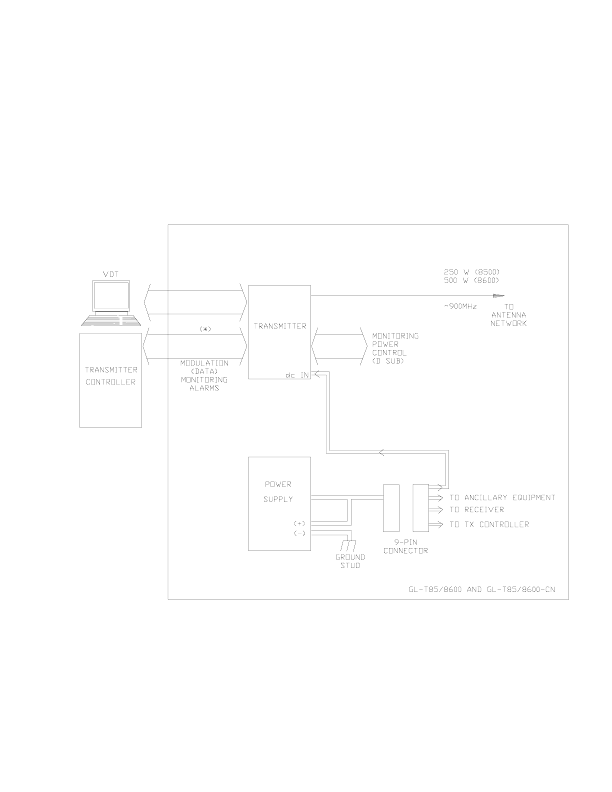
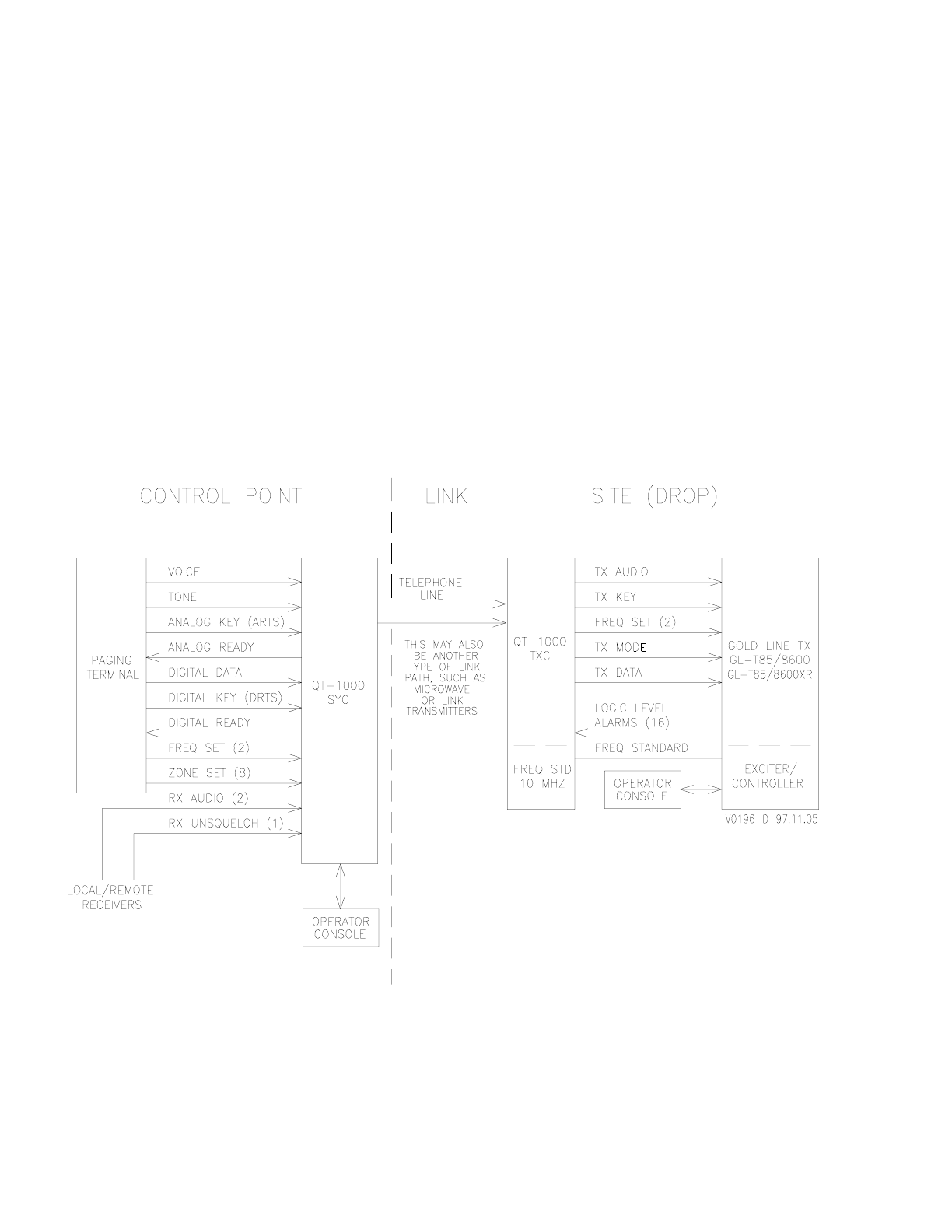
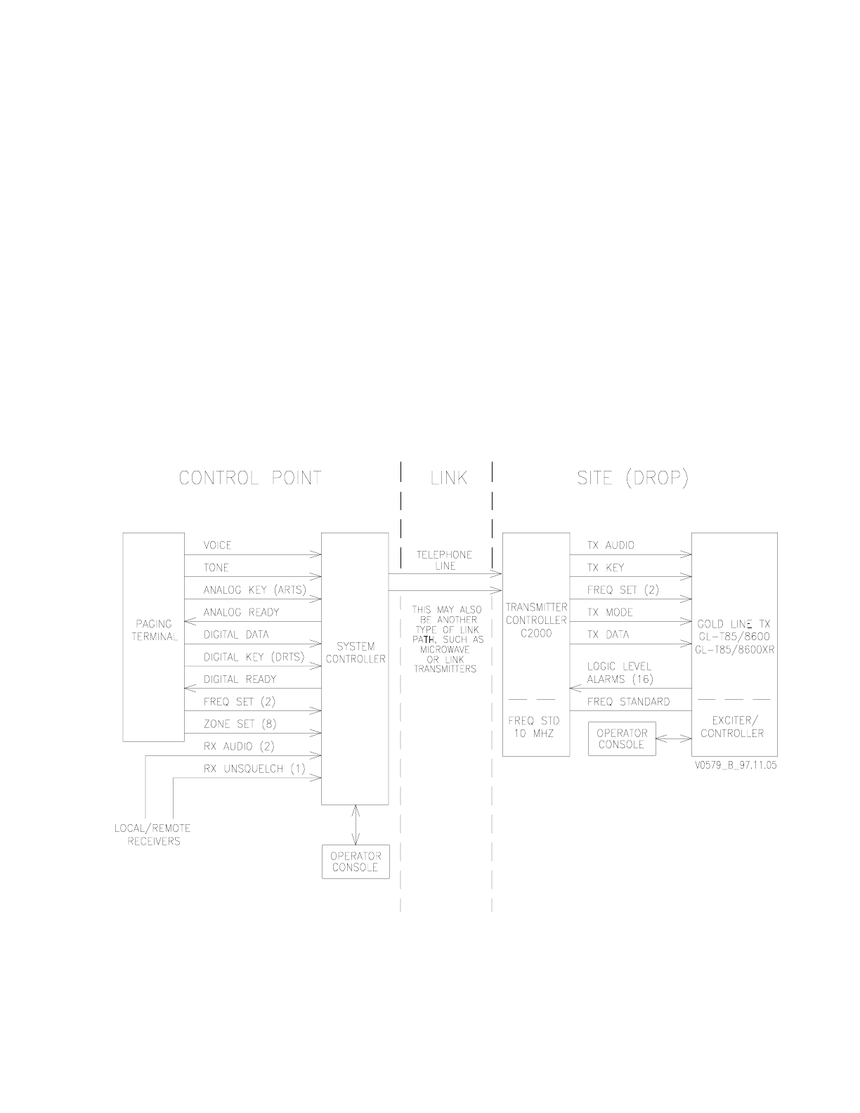
Refer to Figure 6-1 and Figure 6-3. The Gold Line GL-T8500 and GL-T8600 transmitters
operate in a larger paging network. This figure shows how the paging transmitter fits into
the overall paging network.
The following paragraphs provide a block diagram-level functional description of a typical
Gold Line GL-T8500 and GL-T8600 paging sites.
6.2 Simplified Functional Descriptions
6.2.1 Paging Site
Refer to Figure 6-4. This figure shows basic signal flows between the various paging site
equipment pieces.
6.2.2 Paging Transmitter
The Gold Line paging transmitter converts audio from the receiver or wireline, into
modulated and amplified RF. This function is performed in response to commands from the
transmitter controller via the exciter/PA control unit. The transmitter monitors its functions
and reports its status to the VDT via the exciter/PA control unit. The paging signal is
normally supplied via the transmitter controller, which permits the transmitter to be
controlled and monitored from a remote location. Local control and monitoring is
performed through a VT-100 video display terminal (VDT).
Note
If this equipment is to transmit 4-level or higher FSK data, the data lines
(1-4) must not be separated by more than 1.8 microseconds in order to
operate properly.
6.2.3 Exciter / PA Control Unit
The exciter / PA control unit combines functions of an RF exciter and a PA controller. The
exciter generates modulation using digital signal processing (DSP) to achieve accurate,
stable modulation that does not vary with time or temperature. The PA control section
monitors transmitter status signals in the form of fault logic and voltage samples. The
microprocessor in the exciter reports PA status to the controller, VDT, and the exciter front
panel. If a malfunction occurs, the transmitter enters a reduced operating condition
depending on the level of the fault. PA control and status monitoring is performed by the
microprocessor, which consolidates control logic from the controller or the locally operated
VDT. Both the exciter and controller receive continuous status reports from the micropro-
cessor. The exciter is the control and status-monitoring interface between the transmitter
and the user.

GL-T8500-CN/GL-T8600-CN System Manual Glenayre Document Number: 9110.00163
THEORY OF OPERATION Rev. F: 11/09/98
Page: 6-2 Copyright © 1998 Glenayre Print Date: 11/09/98
6.2.4 Power Amplifier
The Gold Line PA performs amplification of the RF signal generated by the exciter. An
indicator visible on the front panel lights when the PA is receiving operating power. The PA
amplifies a nominal 0.25-watt signal to 250 or 500 watts for application to the antenna
system. Monitoring circuitry is on the metering board in the PA chassis. PA functions
include those listed below.
• overheat sensing
• over-current protection
• general fault detection
• output level monitoring
• input level monitoring
6.2.5 Power Supply
The standard Gold Line power supply takes ac input, converts it, rectifies and filters it, and
supplies dc output to all racked equipment. Each dc circuit is individually fused on the front
of the supply. A circuit breaker on the front of the supply doubles as a transmitter power
on/off switch.
6.2.6 Link Receiver
The link receiver monitors specific RF channels for data, command, and control informa-
tion and forwards it to the paging site equipment. The receiver is used in place of a
telephone wireline to link the paging site equipment to the paging network.
6.2.7 Video Display Terminal
The VDT, though not part of the transmitter, is required for setup, local control, and local
monitoring of the transmitter. The VDT can be any laptop or desktop terminal with a VT-
100 type program. The VDT interfaces the transmitter through the connector on the front
of the exciter. The Gold Line transmitter VDT software is menu driven.
6.3 Site Signal Flows
6.3.1 Site RF Signal Flow
The on-frequency carrier is created by the VCO circuitry in the exciter / PA control unit. It
is then modulated with paging information, amplified, and sent to the PA via connector J3
on the back of the exciter / PA control unit. Through coaxial cable, the carrier goes to the
back of the PA where it is further amplified to a preset level. The amplified carrier is cabled
from the PA output to the input of the isolator where it is cleaned up and sent to the antenna
system. Note that some installations have a ten MHz reference signal cabled from the
controller to connector J8 on the back of the exciter / PA control unit.

Glenayre Document Number: 9110.00163 GL-T8500-CN/GL-T8600-CN System Manual
Rev. F: 11/09/98 THEORY OF OPERATION
sec_6
Print Date: 11/09/98 Copyright © 1998 Glenayre Page: 6-3
6.3.2 Site Audio Signal Flow
The audio signal arrives at the site either through a link receiver or by wireline. The signal
can be either analog or digital and is first routed through the transmitter controller. The
controller checks for and responds to appropriate embedded commands. Paging informa-
tion is supplied to the exciter. The exciter modulates this signal using digital signal
processing, then up-converts this modulated signal to final RF. This modulated RF from the
exciter is supplied to the PA, which amplifies the signal to the RF output level. This modu-
lated, amplified RF from the PA is supplied to an antenna for transmission. An audio-
monitoring speaker is available on the RL-903 receiver.
6.3.3 Site Control Signal Flow
Gold Line transmitter paging site control is done two ways: remotely (normal operation),
and locally. In either case, the paging site broadcasts when the transmitter controller
commands the transmitter, via the Gold Line exciter / PA control unit, to key and transmit.
Control functions are shared by the transmitter controller and the G/L exciter / PA control
unit, which controls the power amplifier. The exciter / PA control unit also controls the
power amplifier, locally, by responding to commands from the video display terminal
(VDT).
Control signals enter and exit the paging site via the transmitter controller, which has
overall control of the paging site. The TXC is part of the larger QT-1000 paging control
system even though it is racked with paging site equipment. Controller functions include
those listed below.
• transmitter alarm gathering
• transmitter alarm dispatching
• simulcast parameter implementation
• remote transmitter operation interface.
Remote control of the paging site is done through commands being sent to the transmitter
controller from the external paging control system.
Control commands originating from a remote site are supplied to the exciter through the
controlling device. Control and setup commands may be applied to the exciter locally
through the VDT. A microprocessor within the exciter interprets each command and
responds by performing the appropriate function.
6.3.4 Status Signal Flow
The exciter monitors extensive transmitter status signal in the form of fault logic and
voltage samples. The microprocessor within the exciter reports transmitter status to the
controlling device, VDT, and the exciter front panel. If a transmitter malfunction occurs, a
reduced operating condition is entered depending on the level of the fault.
6.4 Site Signals
Refer to Figure 6-4 and Figure 6-5.
GL-T8500-CN/GL-T8600-CN System Manual Glenayre Document Number: 9110.00163
THEORY OF OPERATION Rev. F: 11/09/98
Page: 6-4 Copyright © 1998 Glenayre Print Date: 11/09/98
Figure 6-1 Paging Network Signal Diagram (w/QT-1000)
Glenayre Document Number: 9110.00163 GL-T8500-CN/GL-T8600-CN System Manual
Rev. F: 11/09/98 THEORY OF OPERATION
sec_6
Print Date: 11/09/98 Copyright © 1998 Glenayre Page: 6-5
Figure 6-2 Paging Network Signal Diagram (w/C2000)

GL-T8500-CN/GL-T8600-CN System Manual Glenayre Document Number: 9110.00163
THEORY OF OPERATION Rev. F: 11/09/98
Page: 6-6 Copyright © 1998 Glenayre Print Date: 11/09/98
Figure 6-3 Site Signal-Flow Diagram
Reserved
Glenayre Document Number: 9110.00163 GL-T8500-CN/GL-T8600-CN System Manual
Rev. F: 11/09/98 THEORY OF OPERATION
sec_6
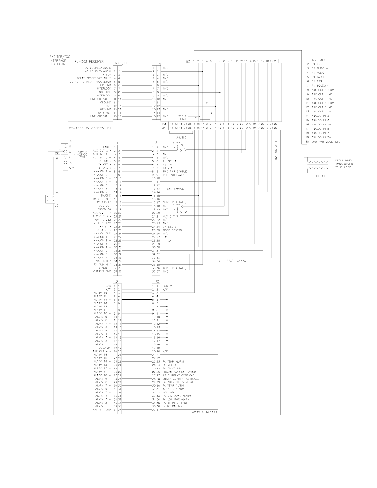
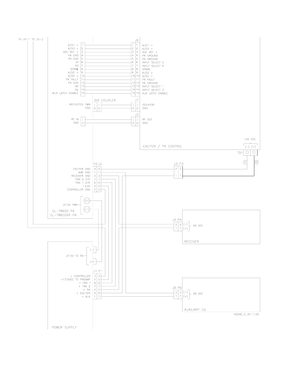
Print Date: 11/09/98 Copyright © 1998 Glenayre Page: 6-7
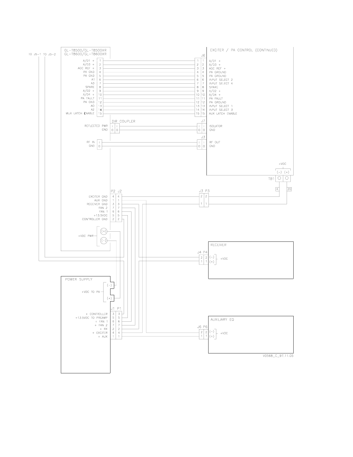
Figure 6-4 Site Signals Diagram (w/QT-1000) (page 1 of 2)
GL-T8500-CN/GL-T8600-CN System Manual Glenayre Document Number: 9110.00163
THEORY OF OPERATION Rev. F: 11/09/98
Page: 6-8 Copyright © 1998 Glenayre Print Date: 11/09/98
Figure 6-4 Site Signals Diagram (page 2 of 2)
Glenayre Document Number: 9110.00163 GL-T8500-CN/GL-T8600-CN System Manual
Rev. F: 11/09/98 THEORY OF OPERATION
sec_6
Print Date: 11/09/98 Copyright © 1998 Glenayre Page: 6-9
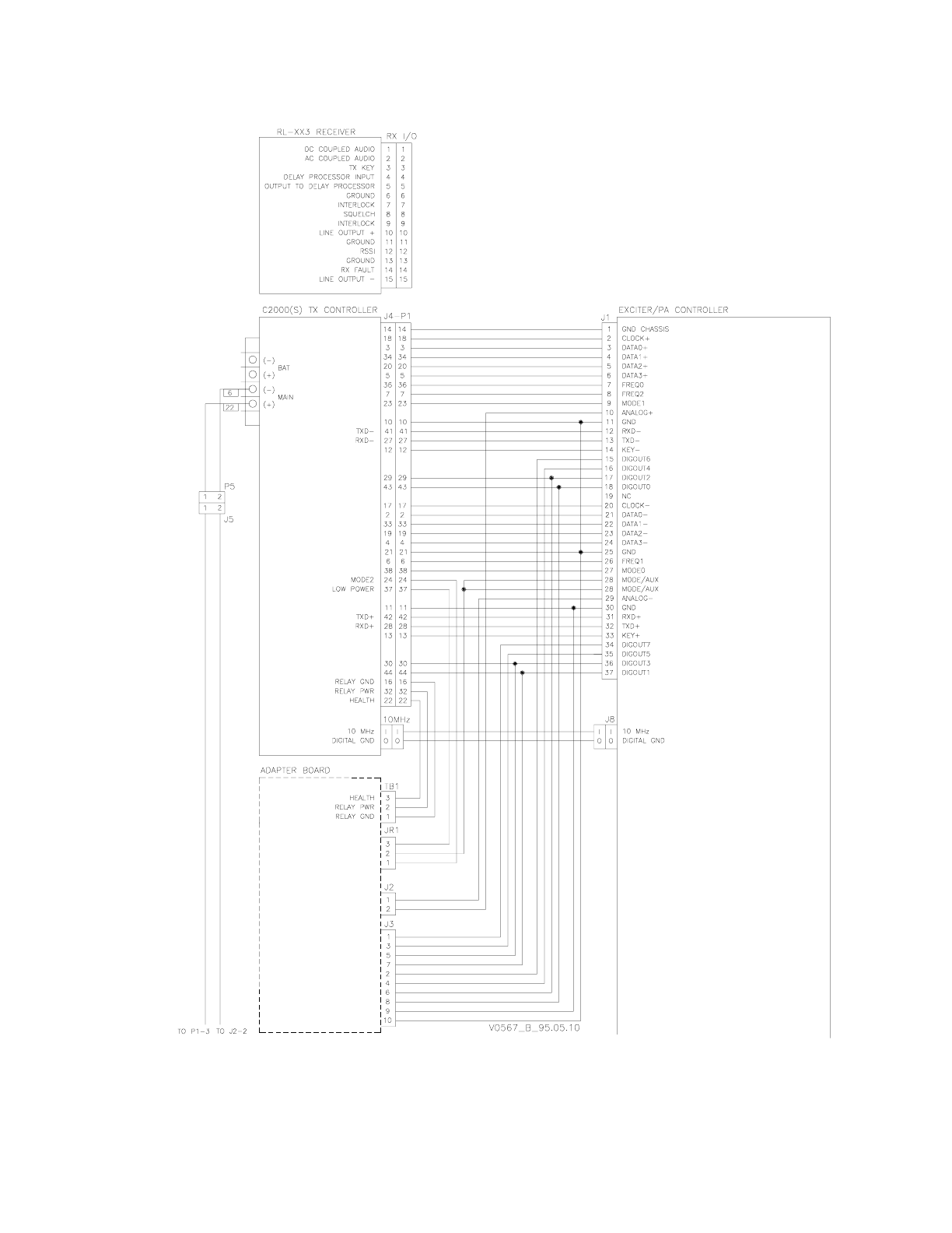
Figure 6-5 Site Signal Diagram (w/C2000) (page 1 of 2)
GL-T8500-CN/GL-T8600-CN System Manual Glenayre Document Number: 9110.00163
THEORY OF OPERATION Rev. F: 11/09/98
Page: 6-10 Copyright © 1998 Glenayre Print Date: 11/09/98
Figure 6-5 Site Signal Diagram (w/C2000) (page 2 of 2)

Glenayre Document Number: 9110.00163 GL-T8500-CN/GL-T8600-CN System Manual
Rev. F: 11/09/98 MAINTENANCE
sec_7
Print Date: 11/09/98 Copyright © 1998 Glenayre Page: 7-1
7 MAINTENANCE
7.1 Introduction
Maintenance procedures in this section are listed below.
• power amplifier current check
• dc ripple check
7.2 Maintenance Procedures
7.2.1 PA Current Check
Once per year the power amplifier device currents should be compared to the levels listed
on the data sheet that accompanied the transmitter. Be sure that the operating RF output is
the same as listed on the data sheet.
• put transmitter in local mode
• key transmitter
• monitor power amplifier currents on VDT
• make comparison between data sheet and monitor
Monitored currents should not vary more than ten percent from data sheet levels. An
exception is when original components or modules have been replaced or modified.
7.2.2 Dc Ripple Check
Once per year the dc supply current should be checked for excessive ripple. Maximum
allowable ripple is given in section two of this manual. The supply should be under normal
operating load for this procedure.
• put transmitter in local mode
• key transmitter
• connect oscilloscope between ground and supply output
• set oscilloscope to read ripple
The observed ripple level should be less than the specification given in section two of this
manual.

GL-T8500-CN/GL-T8600-CN System Manual Glenayre Document Number: 9110.00163
MAINTENANCE Rev. F: 11/09/98
Page: 7-2 Copyright © 1998 Glenayre Print Date: 11/09/98
7.2.3 Audio Level Check (QT-1000 only)
Once per year audio level through the TXC should be checked. To identify components, it
may be necessary to refer to Figure 9-1 in TXC User Manual 9110.0029.
• put transmitter in local mode
• command SYC to send test tone to TXC
• remove to cover of TXC
• observe that LED 9 (yel) not lit; LED 10 (grn) should be lit
The procedure to properly set this audio level is given in section four of this manual.
7.2.4 VDT Maintenance
Other procedures are available through VDT connection to the exciter/PA control unit.
VDT user manual description is given in section one of this manual.

Glenayre Document Number: 9110.00163 GL-T8500-CN/GL-T8600-CN System Manual
Rev. F: 11/09/98 CHECKOUT AND TROUBLESHOOTING
sec_8
Print Date: 11/09/98 Copyright © 1998 Glenayre Page: 8-1
8 CHECKOUT AND TROUBLESHOOTING
8.1 Introduction
Checkout procedures can be performed at any time to verify that the transmitter and related
paging site equipment is functioning properly. After the checkout procedures are success-
fully completed, the site can be returned to normal service. Any troubleshooting procedure
provided or referenced, which is a direct result of a failed checkout procedure, should be
pursued before trying to complete the checkout procedure.
The following procedures presume that the setup procedures in section four of this manual
have already been successfully completed. Refer to the VDT user manual for more
checkout procedures.
8.2 Checkout Procedures
8.2.1 Dc Voltage Verification
Once powered, verify that equipment is powered. Check list below.
• on G/L PA front panel, DC POWER indicator is on
• on G/L exciter front panel, DC POWER indicator is on
• on TXC front panel, STATUS indicator blinks at 1 Hz rate (QT-1000 only)
• on receiver, POWER indicator is on
8.2.2 VDT Power-up Verification
Once powered, verify that the VDT is powered. Check list below.
• the VDT should have a cursor displayed and blinking or
• the VDT should have an instructional prompt displayed or
• the VDT should have an auto-loaded program running
8.2.3 Cooling Fans Check
Once powered, verify that the fans are operating.
8.3 Troubleshooting Procedures
Refer to the VDT user manual for troubleshooting procedures.

GL-T8500-CN/GL-T8600-CN System Manual Glenayre Document Number: 9110.00163
CHECKOUT AND TROUBLESHOOTING Rev. F: 11/09/98
Page: 8-2 Copyright © 1998 Glenayre Print Date: 11/09/98

Glenayre Document Number: 9110.00163 GL-T8500-CN/GL-T8600-CN System Manual
Rev. F: 11/09/98 REMOVAL AND REINSTALLATION
sec_9
Print Date: 11/09/98 Copyright © 1998 Glenayre Page: 9-1
9 REMOVAL AND REINSTALLATION
9.1 Introduction
All of the Gold Line site equipment is accessed from the front of the rack to remove or
install individual equipment pieces.
9.2 Required Tools
Site equipment can be removed and installed using only common hand tools.
9.3 Removal
Equipment removal is performed on a piece by piece method. Disconnect all connecting
cables and wires before removing the equipment. Refer to the individual equipment
manuals for details.
9.4 Reinstallation
Equipment reinstallation is performed on a piece by piece method. Connect all cables and
wires after installing the equipment. Refer to the individual equipment manuals for details.

GL-T8500-CN/GL-T8600-CN System Manual Glenayre Document Number: 9110.00163
REMOVAL AND REINSTALLATION Rev. F: 11/09/98
Page: 9-2 Copyright © 1998 Glenayre Print Date: 11/09/98