Glenayre Electronics GL-T8600-CN Base Station User Manual Users manual part 4
Glenayre Electronics Inc Base Station Users manual part 4
Contents
Users manual part 4
Print Date: 12/17/96 Copyright © 1996 Glenayre
Gold Line VDT Issue 1, Rev. F: 09/03/96
Specifications subject to change without notice
Copyright © 1996 Glenayre
All rights reserved. No part of this work may be reproduced or copied in any form or by
any means—graphic, electronic, or mechanical, including photocopying, recording,
taping, or information-retrieval system—without written permission of Glenayre.
Gold Line VDT
USER MANUAL
PN 9110.00164 (old part number = 916-8A00-002)
REV F
RELEASED
Gold Line VDT Glenayre Document Number: 9110.00164
Document Change Record Issue 1, Rev. F: 09/03/96
Copyright © 1996 Glenayre Print Date: 12/17/96
Document Change Record
Revision: 0, preliminary
Date: 09/03/96
Changes: none, original
Issue: Rev B
Date: 11/19/95
Changes: VDT to DSP Exciter cable
Issue: Rev C
Date: 02/05/96
Changes: new format
Issue: Rev D
Date: 05/15/96
Changes: I20 programming information
Issue: Rev E
Date: 07/10/96
Changes: new menus and menu tree, made released, added I20 overwriting information
Issue: Rev F
Date: 09/03/96
Changes: changed table 4-1 port settings

Glenayre Document Number: 9110.00164 Gold Line VDT
Issue 1, Rev. F: 09/03/96 Table of Contents
Print Date: 12/17/96 Copyright © 1996 Glenayre Page: -i
Table of Contents
1 GENERAL. . . . . . . . . . . . . . . . . . . . . . . . . . . . . . . . . . . . . 1-1
1.1 Manual Scope . . . . . . . . . . . . . . . . . . . . . . . . 1-1
1.2 Applicable Documents. . . . . . . . . . . . . . . . . . . . . 1-1
1.3 Manual Sections . . . . . . . . . . . . . . . . . . . . . . . 1-2
2 REQUIREMENTS . . . . . . . . . . . . . . . . . . . . . . . . . . . . . . . . 2-1
2.1 VDT Requirements . . . . . . . . . . . . . . . . . . . . . . 2-1
2.2 Emulating Program . . . . . . . . . . . . . . . . . . . . . . 2-1
3 DESCRIPTION . . . . . . . . . . . . . . . . . . . . . . . . . . . . . . . . . . 3-1
3.1 Status Display . . . . . . . . . . . . . . . . . . . . . . . . 3-1
3.2 Remote Control . . . . . . . . . . . . . . . . . . . . . . . 3-1
3.3 Local Control . . . . . . . . . . . . . . . . . . . . . . . . 3-2
3.4 Setup. . . . . . . . . . . . . . . . . . . . . . . . . . . . 3-2
4 INSTALLATION AND SETUP . . . . . . . . . . . . . . . . . . . . . . . . . 4-1
4.1 VDT Connection . . . . . . . . . . . . . . . . . . . . . . . 4-1
4.1.1 The VDT to Exciter Interconnect Cable . . . . . . . . . . . . . .4-1
4.1.2 Connecting the VDT to the Transmitter . . . . . . . . . . . . . .4-2
4.2 Starting Up the VDT . . . . . . . . . . . . . . . . . . . . . 4-2
4.2.1 Presetting the Emulating Program . . . . . . . . . . . . . . . . .4-2
4.2.2 Access VDT Communications . . . . . . . . . . . . . . . . . . .4-2
4.2.3 Changing Passwords . . . . . . . . . . . . . . . . . . . . . . . .4-2
4.3 Using the VT-100-Emulating Program . . . . . . . . . . . . . . 4-3
5 OPERATION . . . . . . . . . . . . . . . . . . . . . . . . . . . . . . . . . . . 5-1
5.1 VT-100 Screen Displays . . . . . . . . . . . . . . . . . . . . 5-1
5.1.1 Display Area 1: STATUS. . . . . . . . . . . . . . . . . . . . . .5-1
5.1.2 Display Area 2: CURRENTS . . . . . . . . . . . . . . . . . . . .5-5
5.1.3 Display Area 3: POWERS . . . . . . . . . . . . . . . . . . . . .5-6
5.1.4 Display Area 4:Menu . . . . . . . . . . . . . . . . . . . . . . . .5-7
5.2 Keyboard Operation . . . . . . . . . . . . . . . . . . . . . . 5-7
5.2.1 Numeric Keys . . . . . . . . . . . . . . . . . . . . . . . . . . . .5-7
5.2.2 Enter/Return Key . . . . . . . . . . . . . . . . . . . . . . . . . .5-7
5.2.3 [Esc]. . . . . . . . . . . . . . . . . . . . . . . . . . . . . . . . .5-8
5.2.4 Alphabetic Function Keys . . . . . . . . . . . . . . . . . . . . .5-8
6 MENU TREE . . . . . . . . . . . . . . . . . . . . . . . . . . . . . . . . . . . 6-1
7 CHANGE TX SETTINGS . . . . . . . . . . . . . . . . . . . . . . . . . . . . 7-1
7.1 Select Channel To Adj Fwd Pwr . . . . . . . . . . . . . . . . . 7-2
Gold Line VDT Glenayre Document Number: 9110.00164
Table of Contents Issue 1, Rev. F: 09/03/96
Page: -ii Copyright © 1996 Glenayre Print Date: 12/17/96
7.1.1 Adj Fwd Pwr For Channel . . . . . . . . . . . . . . . . . . . . . 7-3
7.2 Select Channel To Set Low Pwr Alarm . . . . . . . . . . . . . . 7-4
7.2.1 Set Low Pwr Alarm For Channel. . . . . . . . . . . . . . . . . . 7-5
7.3 Enter Password To Set Frequencies Menu. . . . . . . . . . . . . 7-6
7.3.1 Select Channel To Set Frequencies. . . . . . . . . . . . . . . . . 7-7
7.3.2 Set Frequencies For Channel . . . . . . . . . . . . . . . . . . . . 7-8
7.4 Change Frequency Password . . . . . . . . . . . . . . . . . . 7-9
7.5 Change/Toggle Entry Password . . . . . . . . . . . . . . . . . 7-10
7.5.1 Change Entry Password . . . . . . . . . . . . . . . . . . . . . 7-11
8 DIGITAL MODE SETUP . . . . . . . . . . . . . . . . . . . . . . . . . . . . 8-1
8.1 Select Channel To Set 2-Level Deviation . . . . . . . . . . . . . 8-2
8.1.1 Set 2-level Deviation For Channel . . . . . . . . . . . . . . . . . 8-3
8.2 Select Channel To Set 2-Level Offset Menu . . . . . . . . . . . . 8-4
8.2.1 Set 2-level Offset For Channel . . . . . . . . . . . . . . . . . . . 8-5
8.3 Select Channel To Set 4-Level Deviation Menu . . . . . . . . . . 8-6
8.3.1 Set 4-level Deviation For Channel . . . . . . . . . . . . . . . . . 8-7
8.4 Select Channel To Set 4-Level Offset . . . . . . . . . . . . . . 8-8
8.4.1 Set 4-level Offset . . . . . . . . . . . . . . . . . . . . . . . . . . 8-9
8.5 Select Data Polarity . . . . . . . . . . . . . . . . . . . . . 8-10
8.6 Select Filter Risetime . . . . . . . . . . . . . . . . . . . . . 8-11
8.7 Controller Select. . . . . . . . . . . . . . . . . . . . . . . 8-12
9 ANALOG MODE SETUP . . . . . . . . . . . . . . . . . . . . . . . . . . . . 9-1
9.1 Adjust Audio Input Level . . . . . . . . . . . . . . . . . . . 9-2
9.2 Set Analog Deviation . . . . . . . . . . . . . . . . . . . . . 9-3
9.3 Set Analog Limiter Value . . . . . . . . . . . . . . . . . . . 9-4
9.4 Set Analog Offset . . . . . . . . . . . . . . . . . . . . . . 9-5
9.5 Select Audio Response . . . . . . . . . . . . . . . . . . . . 9-6
9.6 Select Audio Polarity . . . . . . . . . . . . . . . . . . . . . 9-7
10 VIEW TX STATUS. . . . . . . . . . . . . . . . . . . . . . . . . . . . . . . . 10-1
10.1 View Voltage Readings . . . . . . . . . . . . . . . . . . . . 10-2
10.1.1 View Channel Freqs . . . . . . . . . . . . . . . . . . . . . . . 10-3
10.2 View Faults Selection. . . . . . . . . . . . . . . . . . . . . 10-4
10.2.1 Present Tx Faults Full-screen Display . . . . . . . . . . . . . . 10-5
10.2.2 Stored Tx Faults Full-screen Display. . . . . . . . . . . . . . . 10-6
10.2.3 View Readings At Fault Full-screen Display. . . . . . . . . . 10-14
10.3 View All Tx Presets Full-Screen Displays. . . . . . . . . . . . 10-15

Glenayre Document Number: 9110.00164 Gold Line VDT
Issue 1, Rev. F: 09/03/96 Table of Contents
Print Date: 12/17/96 Copyright © 1996 Glenayre Page: -iii
11 CALIBRATE FWD/REF PWR . . . . . . . . . . . . . . . . . . . . . . . . .11-1
11.1 Calibrate Fwd Pwr 8500 (8600) . . . . . . . . . . . . . . . . .11-2
11.2 Calibrate Ref Pwr. . . . . . . . . . . . . . . . . . . . . . .11-3
12 CHANGE MODE . . . . . . . . . . . . . . . . . . . . . . . . . . . . . . . . .12-1
13 CHANGE CHANNEL . . . . . . . . . . . . . . . . . . . . . . . . . . . . . .13-1
14 TX SELF TESTS . . . . . . . . . . . . . . . . . . . . . . . . . . . . . . . . .14-1
14.1 Key/Unkey Exciter . . . . . . . . . . . . . . . . . . . . . .14-2
14.2 LEDs Test. . . . . . . . . . . . . . . . . . . . . . . . . .14-3
14.3 AGC Test . . . . . . . . . . . . . . . . . . . . . . . . . .14-4
14.4 Test Alarms . . . . . . . . . . . . . . . . . . . . . . . . .14-6
Gold Line VDT Glenayre Document Number: 9110.00164
Table of Contents Issue 1, Rev. F: 09/03/96
Page: -iv Copyright © 1996 Glenayre Print Date: 12/17/96

Glenayre Document Number: 9110.00164 Gold Line VDT
Issue 1, Rev. F: 09/03/96 List of Figures
Print Date: 12/17/96 Copyright © 1996 Glenayre Page: -v
List of Figures
Figure 4-1 DSP Exciter to VDT Cable. . . . . . . . . . . . . . . . . . . . . . . . 4-1
Figure 7-1 Change Tx Settings Menu . . . . . . . . . . . . . . . . . . . . . . . . 7-1
Figure 7-2 Select Channel To Adj Fwd Pwr Menu. . . . . . . . . . . . . . . . . . 7-2
Figure 7-3 Adj Fwd Pwr For Channel 1 Menu . . . . . . . . . . . . . . . . . . . . 7-3
Figure 7-4 Select Channel To Set Low Pwr Alarm Menu . . . . . . . . . . . . . . 7-4
Figure 7-5 Set Low Power Alarm For Channel 1 Menu . . . . . . . . . . . . . . . 7-5
Figure 7-6 Enter Password To Set Frequencies Menu . . . . . . . . . . . . . . . . 7-6
Figure 7-7 Select Channel To Set Frequencies Menu . . . . . . . . . . . . . . . . 7-7
Figure 7-8 Set Frequencies For Channel All Menu . . . . . . . . . . . . . . . . . 7-8
Figure 7-9 Change Frequency Password Menu . . . . . . . . . . . . . . . . . . . 7-9
Figure 7-10 Change/Toggle Entry Password Menu . . . . . . . . . . . . . . . . . .7-10
Figure 7-11 Change Entry Password Menu . . . . . . . . . . . . . . . . . . . . . .7-11
Figure 8-1 Digital Mode Setup Menu . . . . . . . . . . . . . . . . . . . . . . . . 8-1
Figure 8-2 Select Channel To Set 2-Level Deviation Menu . . . . . . . . . . . . . 8-2
Figure 8-3 Set 2-Level Deviation For Channel All Menu . . . . . . . . . . . . . . 8-3
Figure 8-4 Set Channel To Set 2-Level Offset Menu . . . . . . . . . . . . . . . . 8-4
Figure 8-5 Set 2-Level Offset For Channel All Menu . . . . . . . . . . . . . . . . 8-5
Figure 8-6 Select Channel To Set 4-Level Deviation Menu . . . . . . . . . . . . . 8-6
Figure 8-7 Set 4-Level Deviation For Channel All Menu . . . . . . . . . . . . . . 8-7
Figure 8-8 Set Channel To Set 4-Level Offset Menu . . . . . . . . . . . . . . . . 8-8
Figure 8-9 Set 4-Level Offset For Channel All Menu . . . . . . . . . . . . . . . . 8-9
Figure 8-10 Select Data Polarity Menu . . . . . . . . . . . . . . . . . . . . . . . .8-10
Figure 8-11 Select Filter Risetime Menu . . . . . . . . . . . . . . . . . . . . . . .8-11
Figure 8-12 Controller Select Menu . . . . . . . . . . . . . . . . . . . . . . . . . .8-12
Figure 9-1 Analog Mode Setup Menu . . . . . . . . . . . . . . . . . . . . . . . . 9-1
Figure 9-2 Adjust Audio Level Menu . . . . . . . . . . . . . . . . . . . . . . . . 9-2
Figure 9-2 Set Analog Deviation Menu . . . . . . . . . . . . . . . . . . . . . . . 9-3
Figure 9-2 Set Analog Limiter Value Menu . . . . . . . . . . . . . . . . . . . . . 9-4
Figure 9-3 Set Analog Offset Menu . . . . . . . . . . . . . . . . . . . . . . . . . 9-5
Figure 9-4 Select Audio Response Menu. . . . . . . . . . . . . . . . . . . . . . . 9-6
Figure 9-5 Select Audio Polarity Menu . . . . . . . . . . . . . . . . . . . . . . . 9-7
Figure 10-1 View Tx Status Menu. . . . . . . . . . . . . . . . . . . . . . . . . . .10-1
Figure 10-2 View Voltage Readings Menu . . . . . . . . . . . . . . . . . . . . . .10-2
Figure 10-3 View Channel Frequencies Menu. . . . . . . . . . . . . . . . . . . . .10-3
Figure 10-4 View Faults Selection Menu . . . . . . . . . . . . . . . . . . . . . . .10-4
Gold Line VDT Glenayre Document Number: 9110.00164
List of Figures Issue 1, Rev. F: 09/03/96
Page: -vi Copyright © 1996 Glenayre Print Date: 12/17/96
Figure 10-5 Present Transmitter Faults Menu . . . . . . . . . . . . . . . . . . . . . 10-5
Figure 10-6 Stored Transmitter Faults Menu . . . . . . . . . . . . . . . . . . . . . 10-6
Figure 10-7 View Readings At Fault Menu . . . . . . . . . . . . . . . . . . . . . 10-14
Figure 10-8 View All Transmitter Full-Screen Displays Menu . . . . . . . . . . . 10-15
Figure 11-1 Calibrate Fwd/Ref Pwr Menu . . . . . . . . . . . . . . . . . . . . . . 11-1
Figure 11-2 Calibrate Fwd Pwr Menu . . . . . . . . . . . . . . . . . . . . . . . . . 11-2
Figure 11-3 Calibrate Ref Pwr Menu . . . . . . . . . . . . . . . . . . . . . . . . . 11-3
Figure 12-1 Change Mode Menu . . . . . . . . . . . . . . . . . . . . . . . . . . . 12-1
Figure 13-1 Change Channel Menu . . . . . . . . . . . . . . . . . . . . . . . . . . 13-1
Figure 14-1 Tx Self Tests Menu. . . . . . . . . . . . . . . . . . . . . . . . . . . . 14-1
Figure 14-2 Key/Unkey Exciter Menu . . . . . . . . . . . . . . . . . . . . . . . . 14-2
Figure 14-3 LED Test Menu. . . . . . . . . . . . . . . . . . . . . . . . . . . . . . 14-3
Figure 14-4 AGC Test Menu . . . . . . . . . . . . . . . . . . . . . . . . . . . . . 14-4
Figure 14-5 Alarm Test Select Menu . . . . . . . . . . . . . . . . . . . . . . . . . 14-6
Figure 14-6 Forward Power Calibration Setup/
AGC Reference Test Point Location . . . . . . . . . . . . . . . . . . . 14-7

Glenayre Document Number: 9110.00164 Gold Line VDT
Issue 1, Rev. F: 09/03/96 List of Tables
Print Date: 12/17/96 Copyright © 1996 Glenayre Page: -vii
List of Tables
Table 1-1 Applicable Documents . . . . . . . . . . . . . . . . . . . . . . . . . . 1-1
Table 1-2 Manual Sections . . . . . . . . . . . . . . . . . . . . . . . . . . . . . 1-2
Table 4-1 VT-100 Line Settings . . . . . . . . . . . . . . . . . . . . . . . . . . . 4-2
Table 5-1 Measurements for CURRENTS Display Area. . . . . . . . . . . . . . 5-5
Table 5-2 Measurements for POWERS Display Area. . . . . . . . . . . . . . . . 5-6
Table 10-1 TX Faults Legend Display Description . . . . . . . . . . . . . . . . . .10-7
Gold Line VDT Glenayre Document Number: 9110.00164
List of Tables Issue 1, Rev. F: 09/03/96
Page: -viii Copyright © 1996 Glenayre Print Date: 12/17/96

Glenayre Document Number: 9110.00164 Gold Line VDT
Issue 1, Rev. F: 09/03/96 GENERAL
Print Date: 12/17/96 Copyright © 1996 Glenayre Page: 1-1
1 GENERAL
1.1 Manual Scope
The software discussed in this manual controls GL-T8500 and GL-T8600 transmitters with
the QT-1000 interface. The software resides in a PEROM that installs into the Gold Line
exciter/PA control equipment, part number 265-0082-003.
1.2 Applicable Documents
This manual is incomplete without additional Gold Line manuals. Refer to Table 1-1 for a
listing of these manuals with their part number and a brief description.
Table 1-1 Applicable Documents
document part number description
GL-T8500/8600 system
manual
9110.00163 describes fully racked-up 250/
500-watt, 900-MHz Gold Line
transmitter system with QT-1000
interface
DSP exciter user manual 9110.00172 describes exciter/PA control
equipment for transmitter systems
with interfaces
GL-T8500 power amplifier
manual
9110.00160 describes 250-watt, 900-MHz
Gold Line power amplifier
equipment
GL-T8600 power amplifier
manual
9110.00162 describes 500-watt, 900-MHz
Gold Line power amplifier
equipment
Gold Line VDT manual 9110.00164 this manual
Gold Line 50A/90A power
supply manual
9110.00159 describes power supply equipment
for 250W/500W Gold Line
transmitter systems

Gold Line VDT Glenayre Document Number: 9110.00164
GENERAL Issue 1, Rev. F: 09/03/96
Page: 1-2 Copyright © 1996 Glenayre Print Date: 12/17/96
1.3 Manual Sections
Table 1-2 lists the sections of this manual with a summary of their contents.
Table 1-2 Manual Sections
section contents
1. general introduction and purpose of manual
2. requirements minimum features of VDT
3. description introduction and principal characteristics of software
4. installation and setup initial installation and activation of VDT
5. operation operation of VDT screen and keyboard
6. menu tree menu identification, keystrokes to display menus, in
tree format
7. change TX settings menus that permit forward power adjustment, low
power alarm setting, frequencies setting, frequency
password change, and entry password change/toggle
8. set up digital mode menus that permit 2-level deviation setting, 2-level
offset setting, 4-level deviation setting, 4-level
offset setting, data polarity selection, filter risetime
selection, and controller selection
9. set up analog mode menus that permit audio input level adjustment,
analog deviation setting, analog limiter setting,
analog offset setting, analog response selection, and
analog polarity selection
10. view TX status menus that display voltage readings, channel
frequencies, faults status, and all TX presets
11. calibrate fwd/ref power menus that allow calibration of forward and
reflected power
12. change mode menu that allows selection between analog, 2-level,
and 4-level modes
13. change channel menu that allow selection between channels one
through eight
14. run TX self tests menus that allow: activation of LEDs, AGC, and
alarm test; key/unkey of exciter only; reset of exciter

Glenayre Document Number: 9110.00164 Gold Line VDT
Issue 1, Rev. F: 09/03/96 REQUIREMENTS
Print Date: 12/17/96 Copyright © 1996 Glenayre Page: 2-1
2 REQUIREMENTS
The software described in this manual requires a video display terminal (VDT) with a DEC
VT100-type emulating program. The VDT requirements depend on the type of emulating
program installed.
2.1 VDT Requirements
These requirements are for a VDT with a typical emulating program installed such as
ProComm Plus®.
•computer: an IBM® PC, XT, AT, PS/2 or compatible computer.
•memory: at least 192K of available RAM.
•operating system: PC-DOS or MS-DOS, version 2.0 or later.
•disc drive: at least one floppy drive.
•display: VGA monitor and adapter, or compatible monitor and adapter.
•serial port: with DB-9 or DB-25 connection.
•null modem cable: with male DB-9 connector on transmitter end.
2.2 Emulating Program
These setup requirements are for all DEC VT100-type emulating programs.
•baud rate: 9600
•parity: none
•data bits: 8
•stop bits: 1
•port: serial port interface
Gold Line VDT Glenayre Document Number: 9110.00164
REQUIREMENTS Issue 1, Rev. F: 09/03/96
Page: 2-2 Copyright © 1996 Glenayre Print Date: 12/17/96

Glenayre Document Number: 9110.00164 Gold Line VDT
Issue 1, Rev. F: 09/03/96 DESCRIPTION
Print Date: 12/17/96 Copyright © 1996 Glenayre Page: 3-1
3 DESCRIPTION
The software described in this manual allows interactive operation with GL-T8500 and
GL-T8600 transmitters. Here is a brief list of the transmitter features that the software
operates.
3.1 Status Display
The VDT displays principal transmitter status continuously or specific transmitter status
selectively. Principal status is show in three information blocks at the top of most screens:
•The status block provides present information on 20 critical parameters of the trans-
mitter, in addition to the fault or alarm condition.
•The currents block provides amperage measurements for the dc power input of each
amplifier stage in the power amplifier.
•The powers block provides wattage measurements for forward and reflected RF power
of most amplifier stages in the power amplifier.
The VDT can display more specific transmitter status if desired. Specific status includes
regulated voltage readings, programmed channel frequencies, and four full-screen informa-
tion displays:
•The present faults display lists every transmitter fault or alarm available at the present
moment.
•The stored faults display lists the transmitter fault or alarm that was stored when the
transmitter first left normal operating status.
•The readings at fault display lists the status, currents, and power blocks that were stored
when the transmitter first left normal operating status.
•The presets display lists programmed transmitter parameters for all eight channels.
3.2 Remote Control
When the transmitter is in service and is responding to controller commands, the VDT can
perform remote control functions:
•Adjust the transmitter’s RF power out to any wattage within the transmitter’s rated
forward power.
•Adjust the transmitter’s low power alarm to an RF power out wattage below which the
transmitter provides an alert.
•Program frequencies into channels, if authorized with the frequency password.
Frequency password can be changed.
•Change entry password, used to gain access to VDT. Enable and disable use of entry
password.

Gold Line VDT Glenayre Document Number: 9110.00164
DESCRIPTION Issue 1, Rev. F: 09/03/96
Page: 3-2 Copyright © 1996 Glenayre Print Date: 12/17/96
3.2.1 Software Downloading
Note
C2000/I20 overwrites user changes when in remote mode.
3.3 Local Control
After the VDT has removed the transmitter from service, the VDT can still perform remote
control functions, but now can perform local control functions:
•Key or unkey transmitter.
•Change between analog, 2-level, and 4-level digital modes.
•Change between eight channels.
•Calibrate total forward power (TFP) and total reflected power (TRP) using the appro-
priate external instruments.
•Perform four built-in-tests (BITs) to exciter equipment. Check keyup circuit, AGC
reference circuit, front-panel LEDs, and digital alarm outputs.
•Reboot exciter.
3.3.1 Software Downloading
Note
I20 interface software upgrade overwrites local programming.
3.4 Setup
When the transmitter is initially installed and set up at the paging site, the VDT presets the
analog or digital modes for operation:
•Set number of hertz that the signal deviates the RF carrier.
•Set number of hertz to offset the center of the RF carrier.
•Select inverted or non-inverted input signal polarity.
•Select a filter for the RF output signal.
•Set optimum audio input level (analog mode).
•Set maximum audio input level (analog mode).

Glenayre Document Number: 9110.00164 Gold Line VDT
Issue 1, Rev. F: 09/03/96 INSTALLATION AND SETUP
Print Date: 12/18/96 Copyright © 1996 Glenayre Page: 4-1
4 INSTALLATION AND SETUP
This section requires user manuals for VDT hardware and emulating software. Before
starting this section, verify that all hardware required to run the emulating program has
been installed into the VDT.
4.1 VDT Connection
Connect the VDT to the exciter/PA control equipment using the proper interconnecting
cable. The exciter female DE-9 connector is configured as a serial, DCE, EIA-232 port. The
VDT (or computer) female DB-25 or male DE-9 input is configured as a serial, DTE, EIA-
232 port. The typical serial input connector for the VDT is a female DB-25, and that of most
computers is a male DE-9, but there is no guarantee of this.
4.1.1 VDT-to-Exciter Interconnect Cable
The DSP Exciter to VDT cable can be a straight through DE-9 to DE-9 cable, or a DE-9 to
DB-25, EIA-232 adaptor cable, as shown in Figure 4-1. These cables may be purchased
from a computer shop, adapted using standard EIA-232 parts, or fabricated. The exciter end
of the cable is always a male DE-9 connector. The VDT end can be a male or female DE-
9 or DB-25 connector, check your VDT for the correct connector type.
A 3-conductor cable can be used to fabricate either of the above mentioned cables, as only
the TXD, RXD, and ground connections are needed. Connect the three conductors as
shown in Figure 4-1.
Figure 4-1 DSP Exciter to VDT Cable
8
3
2
20
7
6
4
5
22
DB-25 or DE-9
TO VDT or Computer
1
2
3
4
5
6
7
8
9
DE-9 MALE
TO EXCITER
Note: The solid lines show the conductors necessary for the exciter and VDT (or computer)
to communicate. The dotted lines show the rest of the conductors in the standard cables.
TXD
RXD
GND
1
2
3
4
5
6
7
8
9

Gold Line VDT Glenayre Document Number: 9110.00164
INSTALLATION AND SETUP Issue 1, Rev. F: 09/03/96
Page: 4-2 Copyright © 1996 Glenayre Print Date: 12/18/96
4.1.2 Connecting the VDT to the Transmitter
Connect the VDT to the transmitter using the proper cable(s). Plug the male DB-9 DCE
connector into the jack marked VT-100 INTERFACE located on the front panel of the
exciter/PA control. Plug the other end of the cable or the adapter into one of the VDT's serial
ports. Note the designation of this port for VDT start-up.
4.2 Starting Up the VDT
Apply power to the VDT. If it has not yet been installed, install the emulating program and
all software required to run it.
4.2.1 Presetting the Emulating Program
Select the comm port I/O line settings screen on the VDT. Change the current settings to
those shown in Table 4-1. After you are done, save and exit the line settings screen.
4.2.2 Access VDT Communications
At this point, the VDT should display a screen containing the ENTRY LEVEL
PASSWORD menu. From this menu, perform the following steps:
1. Type ABCD from VDT keyboard. As each letter is typed, an asterisk (*) appears on
the screen under the phrase ENTER PRESENT PASSWORD.
4.2.3 Changing Passwords
When the VDT is connected to the transmitter the first time, a password must be entered in
order to access VT-100 communications. Enter the default password "abcd" to access VT-
100 communications. The VDT uses another password to access channel carrier frequency
assignments. This password is also initially the default password "abcd". It is important to
change these default passwords to secret passwords immediately after the VDT is
connected the first time. By using two passwords, the frequency password may be main-
tained at a higher level of secrecy than the entry password. The entry password may be
disabled if desired to permit immediate access to VT-100 communications. However, even
if it is disabled, it is important to change the entry password to prevent unauthorized
personnel from changing the default password.
Table 4-1 VT-100 Line Settings
parameter setting
baud rate 9600
parity none
data bits 8
stops bits 1
port select desired port
A common abbreviation for the above settings is: 9600 8N1.

Glenayre Document Number: 9110.00164 Gold Line VDT
Issue 1, Rev. F: 09/03/96 INSTALLATION AND SETUP
Print Date: 12/18/96 Copyright © 1996 Glenayre Page: 4-3
4.3 Using the VT-100-Emulating Program
Most VT-100-emulating programs have additional features, some of which can be helpful
when operating the program as a transmitter interface. The program may be capable of
saving the active, or present settings for the RS-232 link with the transmitter. Some
programs have a log function, which saves the keystrokes and displays from the current
session. This feature is particularly useful for saving the transmitter parameters entered
during a setup procedure. When used with a printer, the program may be able to dump the
contents of the present screen display to the printer.
Caution
Some transmitter controllers may issue an alarm if
a transmit command is sent with no resultant
indication of transmitter forward power. This can
be avoided by first placing the transmitter
controller in a mode that does not allow it to issue
alarms.
Gold Line VDT Glenayre Document Number: 9110.00164
INSTALLATION AND SETUP Issue 1, Rev. F: 09/03/96
Page: 4-4 Copyright © 1996 Glenayre Print Date: 12/18/96

Glenayre Document Number: 9110.00164 Gold Line VDT
Issue 1, Rev. F: 09/03/96 OPERATION
Print Date: 12/17/96 Copyright © 1996 Glenayre Page: 5-1
5 OPERATION
5.1 VT-100 Screen Displays
Most VT-100 screens have four display areas as shown below. Display area 1 contains
STATUS information, such as transmitter parameters and conditions. Display area 2
contains the value of CURRENTS through selected active devices within the power ampli-
fier. Display area 3 contains the value of forward or reflected POWERS for selected active
devices within the power amplifier. Display area 4 contains the menu, which permits data
input and selection of other menus. The VT-100 screens that do not have these four display
areas are certain full-screen status displays. This section shows all four STATUS,
CURRENTS, POWERS, and menu display areas, in addition to the full-screen status
displays.
5.1.1 Display Area 1: STATUS
STATUS display area 1 contains two groups of two columns. The transmitter parameter is
in the left column of each group, and its value or condition is in the right column of each
group. The entire display area is repeated and continuously updated on all VT-100 screens
except certain full-screen status displays. The STATUS display area is display-only and
does not permit selections or data entry. The following text describes each parameter and
condition displayed in the STATUS display area.
FWD PWR (Forward Power)
This display lists the transmitter's actual forward RF output power in watts. Sometimes
described as total forward power, the value for this display is measured at the output of the
PA's combiner board.
REF PWR (Reflected Power)
This display lists the transmitter's actual reflected RF power in watts. Sometimes described
as total reflected power, the value for this display is measured at the isolator module on the
rear of the PA.
EXC 26V (Exciter 26 Volts)
This display lists the exciter's actual 26-volt operating voltage. This voltage is measured at
the power input of the exciter/PA control, and is normally supplied by the transmitter's 26-
volt power supply.
AGC (Automatic Gain Control)
This display lists the AGC voltage, a dc voltage that controls the gain of the power amplifier.
This voltage, generated by the PA metering board, is measured at the preamplifier (first
stage) on the PA's driver board.

Gold Line VDT Glenayre Document Number: 9110.00164
OPERATION Issue 1, Rev. F: 09/03/96
Page: 5-2 Copyright © 1996 Glenayre Print Date: 12/17/96
Note
Do not confuse AGC voltage generated in the PA with AGC reference
voltage generated in the exciter/PA control. The PA's AGC voltage is
produced by comparing AGC reference voltage against transmitter
forward power.
V001 (Voltage-Controlled Oscillator 1)
This display lists the dc control voltage for VCO-1, in the exciter/PA control IF stage
circuitry. The VCO1 control voltage, necessary for phase-locking the VCO-1 carrier to the
10-MHz reference signal, is generated by synthesizer-1.
V002 (Voltage-Controlled Oscillator 2)
This display lists the dc control voltage for VCO-2, in the exciter/PA control RF stage
circuitry. The VCO2 control voltage, necessary for phase-locking the VCO-2 carrier to the
10-MHz reference signal, is generated by synthesizer-2.
TEMP (Temperature)
This display lists the temperature in degrees centigrade measured at the heat sink on the
back of the PA.
CTRL VER (Control Version)
This display lists the version number for the MCU software that is presently installed in the
exciter/PA control. It is the version of software installed in the programmable and erasable
read-only memory (PEROM) for the MCU.
DSP VER (DSP Version)
This display lists the version number for the DSP software that is presently installed in the
exciter/PA control. It is the version of software installed in the programmable and erasable
read-only memory (PEROM) for the DSP.
P/N (Part Number)
This display lists the part number of U3, the PEROM for the MCU. The present version of
software for the MCU, designated by the CTRL VER display, is installed in U3.
DEVIATION
This display lists signal deviation values and other relative status items. The operation of
the deviation display is dependent on the transmitter operating mode presently selected:
digital FSK or analog.
Digital FSK Mode
•When no input data is present, the DEVIATION display lists NO DATA.

Glenayre Document Number: 9110.00164 Gold Line VDT
Issue 1, Rev. F: 09/03/96 OPERATION
Print Date: 12/17/96 Copyright © 1996 Glenayre Page: 5-3
•When input data is present, the DEVIATION display lists the programmed deviation
value for the channel and digital level currently selected. This value is the difference, in
Hz, between f0 and the highest FSK frequency, and between f0 and the lowest FSK
frequency. See OFFSET for a description of f0.
Analog Mode
•When in analog mode and no input signal is present above 100 Hz, the DEVIATION
display lists 0 Hz
•When in analog mode and an input signal is present above the programmed limiting
value, causing the transmitter to impose deviation limiting, the DEVIATION display lists
LIMIT.
•When in analog mode and an input signal is present above 100 Hz and below the
programmed limiting value, the DEVIATION display lists the actual deviation value.
This value is the number of Hz between f0 and the highest modulated frequency, and
between f0 and the lowest modulated frequency. See OFFSET for a description of f0.
OFFSET
This display lists the programmed offset value for the mode currently selected, and, when
in the digital FSK mode, for the channel currently selected. This offset of the channel
frequency is needed in order to reduce overlap area nulls when simulcasting. Offset value
is the number of Hz added to or subtracted from the channel frequency to create the center
frequency (digital FSK mode) or carrier frequency (analog mode), also known as f0.
MODE
This display lists the presently selected operating mode and, when in analog mode, also lists
the audio response.
•If 2-LEVEL is listed, two-level FSK mode is selected.
•If 4-LEVEL is listed, four-level FSK mode is selected.
•If ANLG-FLAT is listed, analog mode and audio response for flat is selected.
•If ANLG-PRE is listed, analog mode and audio response for preemphasis is selected.
CHANNEL
This display lists the number (1 through 8) of the transmitter channel that
is currently selected.
FREQ (Frequency)
This display lists the programmed channel frequency, in MHz, for the channel currently
selected.
DATA POL or ANLG POL
This display lists the programmed input signal polarity state for the presently selected
mode. The title of this display item is DATA POL if 2-level or 4-level FSK modes are
presently selected; the title is ANLG POL if analog mode is presently selected. NON-INV
is listed to indicate the programmed input signal polarity state is noninverted. INV is listed
to indicate the programmed input signal polarity state is inverted. The result of input signal
polarity inversion is dependent on the mode presently selected.
Gold Line VDT Glenayre Document Number: 9110.00164
OPERATION Issue 1, Rev. F: 09/03/96
Page: 5-4 Copyright © 1996 Glenayre Print Date: 12/17/96
DATA POL (Polarity)
•When in 2-level FSK mode and NON-INV is listed_, data "1" generates a frequency
above f0 and data "0" generates a frequency below f0.
•When in 2-level FSK mode and INV is listed, data "1" generates frequency below f0 and
data "0" generates a frequency above f0.
•When in 4-level FSK mode and NON-INV is listed, data "10" and data "11" generate
frequencies above f0. Data "01" and data "00" generate frequencies below f0.
•When in 4-level FSK mode and INV is listed, data "10" and data "11" generate frequen-
cies below f0. Data "01" and data "00" generate frequencies above f0. Note that data is
rearranged, not just inverted (3-4/2-1 to 2-1/4-3).
ANLG POL (analog polarity)
•When in analog mode and NON-INV is listed, a positive voltage into audio (+) causes a
positive deviation from f0 and a negative voltage into audio (+) causes a negative
deviation from f0.
•When in analog mode and INV is listed, a positive voltage into audio (+) causes a
negative deviation from f0 and a negative voltage into audio (+) causes a positive
deviation from f0.
CONTROL
This display lists the transmitter's presently selected control state. This state is listed either
as LOCAL or REMOTE.
•REMOTE - this is the transmitter's normal operating mode. External control inputs such
as channel, mode, and key commands are supplied by a device such as a transmitter
controller and are obeyed by the transmitter. These commands are not possible through
the VT-100 interface when in the remote control mode.
•LOCAL - this is the transmitter's maintenance mode. External control inputs such as
channel, mode, and key commands are ignored by the transmitter. These commands, in
addition to maintenance, setup, and self test functions, are possible through the VT-100
interface when in the local control mode.
KEY STATE
This display lists the transmitter's presently selected key input state. This state is listed as
KEYED or UNKEYED. The logic for this condition is detected in the exciter/PA control. A
keyed condition indicates an external key hardline activation (in the remote control mode)
or a VT-100 VDT [K] key software selection (in the local control mode).
FILTER
This display lists the rise time, in microseconds, of the presently selected digital premodu-
lation filter. This rise time is effective for the digital FSK modes only, although it is always
displayed regardless of mode.
CHAN BW (Channel Bandwidth)
This display lists maximum bandwidth, in kHz, of all the transmitter channels. The
bandwidth is determined by the filtering circuitry installed in the exciter/PA control.

Glenayre Document Number: 9110.00164 Gold Line VDT
Issue 1, Rev. F: 09/03/96 OPERATION
Print Date: 12/17/96 Copyright © 1996 Glenayre Page: 5-5
FAULT or ALARM
This display is normally blank, unless a transmitter malfunction has occurred that can be
detected by the transmitter's monitoring system. In the event that a transmitter malfunction
is detected, FAULT or ALARM appears as inverted video. The display is reset after each key
cycle, unless a serious malfunction prevents the transmitter from keying up. The serious-
ness of the malfunction is indicated as FAULT or ALARM.
ALARM
A less serious transmitter malfunction has occurred, requiring an operator alert but still
permitting normal transmitter operation.
FAULT
A more serious transmitter malfunction has occurred, requiring an operator alert and
causing the transmitter to shut down or reduce power, thus preventing further transmitter
damage.
5.1.2 Display Area 2: CURRENTS
CURRENTS display area 2 contains three groups of two columns. The active devices within
the PA are in the left column of each group, and their currents are in the right column of
each group. The entire display area is repeated and continuously updated on all VT-100
screens except for certain full-screen status displays. The CURRENTS display area is
display-only and does not permit selections or data entry. Table 5-1 lists each item in the
left column of each group, and describes the measurement that determines its currents value
in the right column of each group.
Table 5-1 Measurements for
CURRENTS
Display Area
item measurement
PREAMP current through preamplifier (first stage) on driver board
DRVR1 current through transistor on driver board that supplies RF to PA1 board
DRVR2 current through transistor on driver board that supplies RF to PA2 board
DRVR3 current through transistor on driver board that supplies RF to PA3 board
DRVR4 current through transistor on driver board that supplies RF to PA4 board
IPA current through intermediate PA transistor (second stage) on driver
board
PA1-A current through transistor pair A on PA1 board
PA2-A current through transistor pair A on PA2 board
PA3-A current through transistor pair A on PA3 board

Gold Line VDT Glenayre Document Number: 9110.00164
OPERATION Issue 1, Rev. F: 09/03/96
Page: 5-6 Copyright © 1996 Glenayre Print Date: 12/17/96
5.1.3 Display Area 3: POWERS
POWERS display area 3 contains three groups of two columns. The active devices within
the PA and the direction of their measurements are in the left column of each group. The
powers in watts are in the right column of each group. The entire display area is repeated
and continuously updated on all VT-100 screens except for certain full-screen status
displays. The POWERS display area is display-only and does not permit selections or data
entry. Table 5-2 lists each item in the left column of each group, and describes the measure-
ment that determines its powers value in the right column of each group.
5.1.4 Display Area 4:Menu
The remainder of this section describes the menu display area 4. Unlike the other three
display areas, most menus permit data input and parameter selection. Each menu is
described in five parts: access procedure, sample menu, menu function, menu operation,
and active alpha function key list.
PA4-A current through transistor pair A on PA4 board
PA1-B current through transistor pair B on PA1 board
PA2-B current through transistor pair B on PA2 board
PA3-B current through transistor pair B on PA3 board
PA4-B current through transistor pair B on PA4 board
Table 5-2 Measurements for POWERS Display Area
item measurement
IPA FWD forward power out of second stage on driver board
IPA REF reflected power into second stage on driver board
PA1 FWD forward power out of PA1 board
PA2 FWD forward power out of PA2 board
PA3 FWD forward power out of PA3 board
PA4 FWD forward power out of PA4 board
PA1 REF reflected power into PA1 board output
PA2 REF reflected power into PA2 board output
PA3 REF reflected power into PA3 board output
PA4 REF reflected power into PA4 board output
Table 5-1 Measurements for
CURRENTS
Display Area (continued)
item measurement

Glenayre Document Number: 9110.00164 Gold Line VDT
Issue 1, Rev. F: 09/03/96 OPERATION
Print Date: 12/17/96 Copyright © 1996 Glenayre Page: 5-7
1. Access Procedure - an access procedure is included at the top of each page just be-
low the menu title. The access procedure describes the keystrokes or other actions re-
quired to display this menu.
2. Sample Menu - a sample menu is outlined by a square. This sample shows the typical
contents of display area 4 when the menu is selected.
3. Menu Function - a menu function describes the purpose of the menu.
4. Menu Operation - a menu operation describes how to use the menu.
5. Active Alpha Function Keys - an active alpha function key list is at the bottom of
each page. This list contains the alphabetical keys, active when the menu is displayed,
that have been assigned a predetermined software function. The predetermined soft-
ware function of these alpha keys is described in the previous introductory Section 4.
5.2 Keyboard Operation
Depending upon the displayed menu, the keys most often used on the keyboard are the
numeric keys, enter/return key, [ESC], and alphabetic function keys.
5.2.1 Numeric Keys
The numeric keys are used to select a menu or transmitter parameter, or to enter a value into
a data input field. The numeric keys on the keypad function identically to those on the main
keyboard if [NUM LOCK] is enabled.
If the menu contains a list of numbered options, a single press of a numeric key produces
the menu or function desired. No further keystrokes are required if the number pressed was
one of the options.
If the menu contains a data input field, more than one keystroke is usually required to
produce the desired function. Pressing numeric keys causes the value to appear in this data
input field, in the space underlined by the cursor. The backspace key is functional during
this procedure. After typing a value into the data input field, a press of enter/return is
required to activate the value.
5.2.2 Enter/Return Key
This key is labeled Enter, Return, or abbreviations thereof, depending upon the keyboard.
This key performs the same enter function regardless of label, and so is called [ENTER].
The key is used to activate a value that has been typed into a data input field.
When a data input field first appears, it already contains the default value or the last value
entered by previous keystrokes. A cursor located to the left of this value indicates where a
typed numeral will appear. As the new value is typed into the data input field, the old value
disappears and the cursor flows to the right of the new value. After [ENTER] is pressed,
the cursor resets to the left to indicate the new value has become the operative value.
Gold Line VDT Glenayre Document Number: 9110.00164
OPERATION Issue 1, Rev. F: 09/03/96
Page: 5-8 Copyright © 1996 Glenayre Print Date: 12/17/96
5.2.3 [Esc]
The [ESC], or escape key, is active when all except top-level menus are displayed. Pressing
the escape key causes the previous menu to be displayed. The previous menu is the next-
higher level, or one menu back. The escape key will not work if a Main Menu (remote or
Local) is displayed.
5.2.4 Alphabetic Function Keys
Alphabetic function keys are a group of letters that, when pressed, cause a predetermined
activity to occur. Only some keys are active when a particular menu is displayed. An active
alphabetic function key list is provided for each menu. The following is a list of all the
alphabetic function keys:
•M (display main menu)
•R (refresh main menu)
•K (key or unkey TX)
•A (select all channels)
•Y (yes, perform request)
•N (no, do not perform request)
•U (adjust value upwards)
•D (adjust value downwards)
M Key
Pressing the M (main menu) key causes a main menu to be displayed, if it is not already
displayed. If the transmitter is in remote control, the M key displays the Remote Control
Main Menu. If the transmitter is in local control, the M key displays the Local Control Main
Menu.
R Key
Pressing the R (refresh) key causes a main menu to be displayed if it is not already
displayed (the same as pressing the M key). The R key also causes the transmitter to update
the status, currents, and powers values in the top half of the screen.
K Key
Pressing the K (key) key causes the transmitter to key, if unkeyed, or to unkey, if already
keyed. The K key is active in local control only. When local control is entered, the K key
is activated and the transmitter unkeys, if already keyed. When local control is exited, the
K key is deactivated and the transmitter assumes the key state determined by the remote
key input.
A Key
Pressing the A (all) key causes the channel-all menu to be displayed for the parameter
presently selected. This key allows selection or change of a transmitter parameter for all
channels simultaneously, without having to select each channel individually.

Glenayre Document Number: 9110.00164 Gold Line VDT
Issue 1, Rev. F: 09/03/96 OPERATION
Print Date: 12/17/96 Copyright © 1996 Glenayre Page: 5-9
U and D Keys
Pressing the U (up) or D (down) key causes an incremental adjustment to the value for the
parameter displayed. These keys permit numerous adjustments to a transmitter parameter
value without having to enter the entire value many times.
Y and N Keys
Pressing the Y (yes) or N (no) key causes a positive or negative response to a question being
asked by the displayed menu. These keys are used when selecting or changing an important
transmitter parameter.
Gold Line VDT Glenayre Document Number: 9110.00164
OPERATION Issue 1, Rev. F: 09/03/96
Page: 5-10 Copyright © 1996 Glenayre Print Date: 12/17/96

Glenayre Document Number: 9110.00164 Gold Line VDT
Issue 1, Rev. F: 09/03/96 MENU TREE
Print Date: 12/17/96 Copyright © 1996 Glenayre Page: 6-1
6 MENU TREE
Note
C2000/I20 overwrites user changes when in remote mode. I20 interface
software upgrade overwrites local programming.
MAIN MENU
1 CHANGE TX SETTINGS see page 7-1
ADJ FWD PWR see page 7-2
Select Channel to Adj Fwd Pwr see page 7-2
Adj Fwd Pwr For Channel see page 7-2
SET LOW PWR ALRM see page 7-3
Select Channel To Set Low Pwr Alarm see page 7-3
Set Low Pwr Alarm For Channel see page 7-3
SET FREQUENCIES see page 7-4
Enter Password to Set Frequencies see page 7-4
Select Channel To Set Frequencies see page 7-4
Set Frequencies For Channel see page 7-5
CHANGE FREQUENCY PASSWORD see page 7-6
CHANGE/TOGGLE ENTRY PASSWORD see page 7-7
Change Entry Password see page 7-7
2 DIGITAL MODE SETUP see page 8-1
SET DEVIATION see page 8-1
Select Channel To Set Mode Deviation see page 8-2
Set Mode Deviation For Channel see page 8-2
SET OFFSET see page 8-3
Select Channel To Set Mode Offset see page 8-3
Set Mode Offset For Channel see page 8-4
SELECT DATA POLARITY see page 8-4
SELECT FILTER RISETIME see page 8-5
Select Channel To Set Filter Risetime see page 8-5
Select Filter Risetime for Channel see page 8-5
3 ANALOG MODE SETUP see page 9-1
ADJUST AUDIO INPUT LEVEL see page 9-1
SET ANALOG DEVIATION see page 9-2
SET ANALOG LIMITER VALUE see page 9-2
SET ANALOG OFFSET see page 9-3
SELECT AUDIO RESPONSE see page 9-3
SELECT AUDIO POLARITY see page 9-4
4 VIEW TX STATUS see page 10-1
VIEW VOLTAGE READINGS see page 10-2
VIEW CHANNEL FREQS see page 10-2
VIEW FAULTS SELECTION see page 10-3
Gold Line VDT Glenayre Document Number: 9110.00164
MENU TREE Issue 1, Rev. F: 09/03/96
Page: 6-2 Copyright © 1996 Glenayre Print Date: 12/17/96
View Present Faults see page 10-3
View Stored Faults see page 10-4
View Stored Fault Readings see page 10-12
View Readings At Fault see page 10-12
View/Reset DSP Faults see page 10-12
VIEW ALL TX PRESETS see page 10-13
5 EXIT LOCAL CONTROL see other main menu items for description
6 CALIBRATE FWD/REF PWR see page 11-1
CALIBRATE FWD PWR see page 11-2
CALIBRATE REF PWR see page 11-3
7 CHANGE MODE see page 12-1
8 CHANGE CHANNEL see page 13-1
9 TESTS/UPLOAD see page 14-1
KEY/UNKEY EXCITER see page 14-1
LEDS TEST see page 14-2
N/A
RESET EXCITER see page 14-3
TEST ALARMS see page 14-3
UPDATE FIRMWARE see page 14-4

Glenayre Document Number: 9110.00164 Gold Line VDT
Issue 1, Rev. F: 09/03/96 MENU TREE
Print Date: 12/17/96 Copyright © 1996 Glenayre Page: 6-3
Gold Line VDT Glenayre Document Number: 9110.00164
MENU TREE Issue 1, Rev. F: 09/03/96
Page: 6-4 Copyright © 1996 Glenayre Print Date: 12/17/96

Glenayre Document Number: 9110.00164 Gold Line VDT
Issue 1, Rev. F: 09/03/96 CHANGE TX SETTINGS
Print Date: 12/17/96 Copyright © 1996 Glenayre Page: 7-1
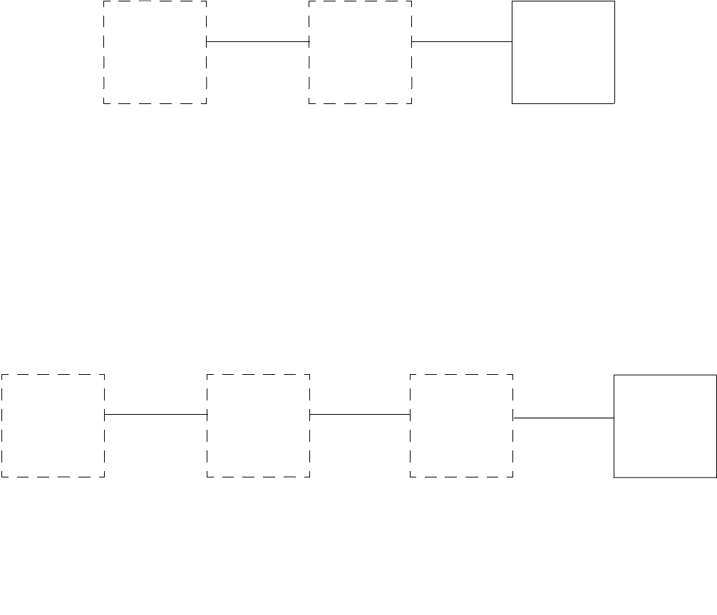
7 CHANGE TX SETTINGS
Refer to following diagram for initial steps of Change Tx Settings procedure.
•Select option to ADJ FWD PWR
•Select option to SET LOW PWR ALRM
•Select option to SET FREQUENCIES
•Select option to CHANGE FREQUENCY PASSWORD
•Select option to CHANGE/TOGGLE ENTRY PASSWORD
MAIN
MENU
(REMOTE
OR LOCAL)
CHANGE
TX
SETTINGS

Gold Line VDT Glenayre Document Number: 9110.00164
CHANGE TX SETTINGS Issue 1, Rev. F: 09/03/96
Page: 7-2 Copyright © 1996 Glenayre Print Date: 12/17/96
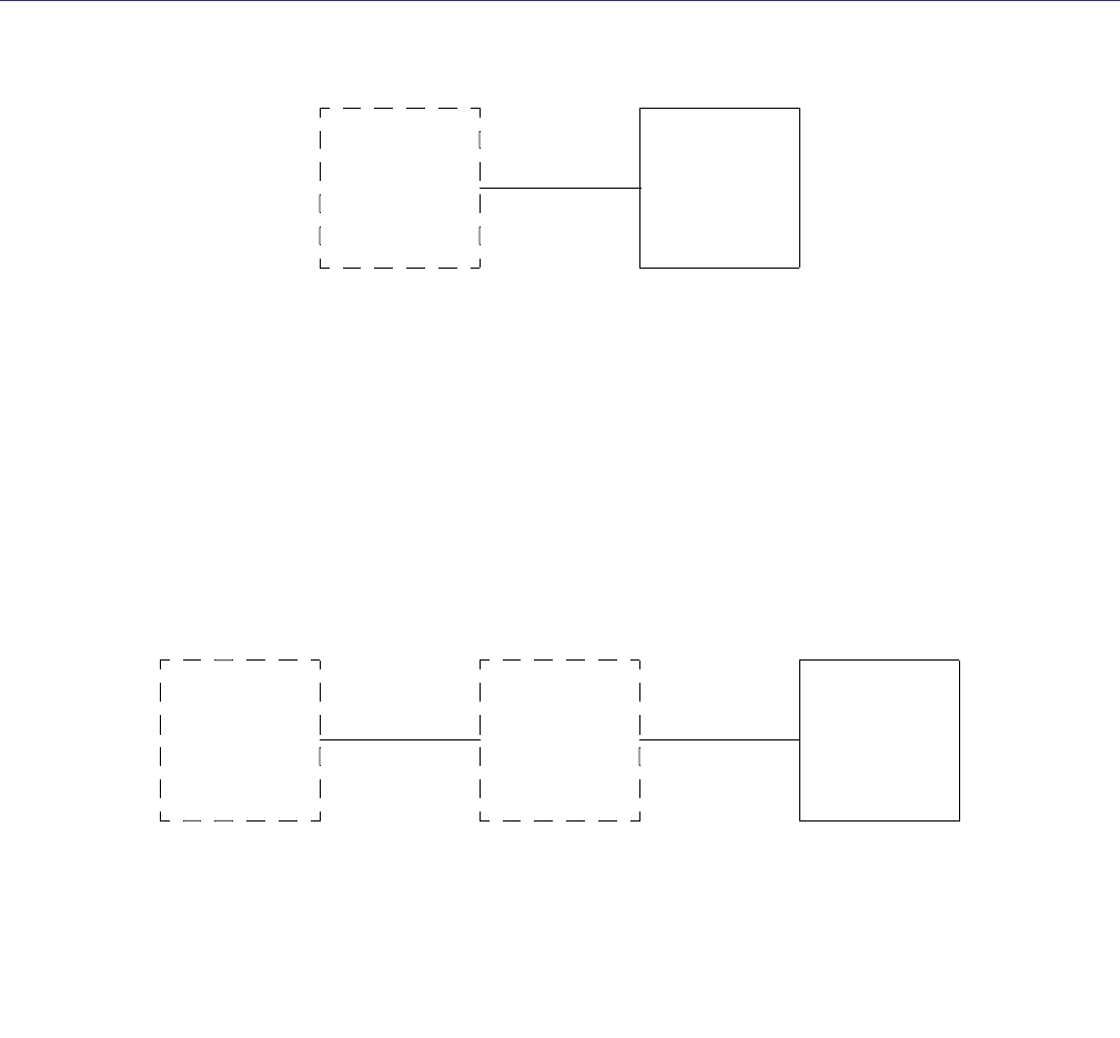
7.1 ADJ FWD PWR
7.1.1 SELECT CHANNEL TO ADJ FWD PWR
Refer to the following diagram for initial steps of Select Channel to Adjust Forward Power
Procedure.
•To set one channel to a different forward power than other channels, press numeric key
that corresponds to that channel. A menu to adjust forward power for one channel
appears.
•To set forward power for all channels simultaneously, press A. A menu to adjust forward
power for all channels appears. Refer to next paragraph for more information.
7.1.1.1 Adj Fwd Pwr For Channel
Refer to following diagram for initial steps of Adjust Forward Power For Channel
Procedure.
•For incremental adjustments, press U to increase or D to decrease forward power shown
in shaded area. Forward power must remain between wattage limits stated on screen.
•For entry of a specific value, press numeric keys to input forward power into shaded area.
Forward power must be whole number between wattage limits stated on screen. Press
Enter to store value and reset cursor.
MAIN
MENU
(REMOTE
OR LOCAL)
CHANGE
TX
SETTINGS
ADJ FWD
PWR
SELECT
CHANNEL
TO ADJ FWD
PWR
CHANGE
TX
SETTINGS
MAIN
MENU
(REMOTE
OR LOCAL)
ADJ FWD
PWR FOR
CHANNEL
ADJ FWD
PWR
SELECT
CHANNEL
TO ADJ FWD
PWR

Glenayre Document Number: 9110.00164 Gold Line VDT
Issue 1, Rev. F: 09/03/96 CHANGE TX SETTINGS
Print Date: 12/17/96 Copyright © 1996 Glenayre Page: 7-3
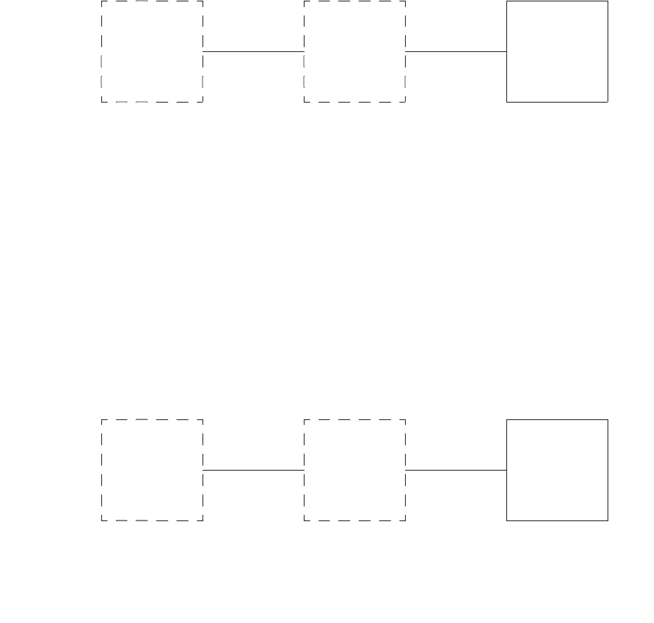
7.2 Set Low Pwr Alrm
7.2.1 Select Channel To Set Low Pwr Alarm
Refer to following diagram for initial steps of Select Channel To Set Low Power Alarm
Procedure.
•To set one channel to a different low power alarm than other channels, press numeric key
that corresponds to that channel. A menu to set low power alarm for one channel appears.
•To set low power alarm for all channels simultaneously, press A. A menu to set low
power alarm for all channels appears. Refer to next paragraph for more information.
7.2.1.1 Set Low Pwr Alarm For Channel
Refer to following diagram for initial steps of Set Low Power Alarm For Channel
Procedure.
•Press numeric keys to input desired alarm level into shaded area. Alarm level must be a
whole number between wattage limits stated on screen.
•Set deviation to maximum setting without causing channel interference.
•Press Enter to store deviation and reset cursor.
CHANGE
TX
SETTINGS
MAIN
MENU
(REMOTE
OR LOCAL)
SET LOW
PWR ALARM
SELECT
CHANNEL
TO SET LOW
PWR ALARM
CHANGE
TX
SETTINGS
MAIN
MENU
(REMOTE
OR LOCAL)
SET LOW
PWR ALRM SET LOW
PWR
ALARM FOR
CHANNEL
SELECT
CHANNEL
TO SET LOW
PWR ALARM

Gold Line VDT Glenayre Document Number: 9110.00164
CHANGE TX SETTINGS Issue 1, Rev. F: 09/03/96
Page: 7-4 Copyright © 1996 Glenayre Print Date: 12/17/96
7.3 Set Frequencies
7.3.1 Enter Password To Set Frequencies
Refer to following diagram for initial steps of Enter Password To Set Frequencies
procedure.
•Press keys corresponding to frequency password. Asterisk (*) appears in shaded area as
each key is pressed.
•Press Enter. A screen to select channel to set frequencies appears if password is correct.
Refer to next paragraph for more information.
7.3.1.1 Select Channel To Set Frequencies
Refer to following diagram for initial steps of Select Channel To Set Frequencies
procedure.
•To set one channel to a different frequency than other channels, press numeric key that
corresponds to that channel. A menu to set frequency for one channel appears.
•To set frequency for all channels simultaneously, press A. A menu to set frequencies for
all channels appears.
ENTER
PASSWORD
TO SET
FREQUEN-
CIES
MAIN
MENU
(REMOTE
OR LOCAL)
CHANGE
TX
SETTINGS
SET
FREQUEN-
CIES
MAIN
MENU
(REMOTE
OR LOCAL)
ENTER
PASSWORD
TO SET
FREQUEN-
CIES
SELECT
CHANNEL
TO SET
FREQUEN-
CIES
CHANGE
TX
SETTINGS
SET
FREQUEN-
CIES

Glenayre Document Number: 9110.00164 Gold Line VDT
Issue 1, Rev. F: 09/03/96 CHANGE TX SETTINGS
Print Date: 12/17/96 Copyright © 1996 Glenayre Page: 7-5
7.3.1.1.1 Set Frequencies For Channel
Refer to following diagram for initial steps of Set Frequencies For Channel procedure.
.
Note
Different frequency ranges appear for different bands. The ranges which
are available to you, correspond to the available frequency range of the
exciter, except in cases where the frequency band is subdivided (banded)
so that frequencies selected must be within the range of resonant parts.
For example, if your range is 920-960 MHz, you may legitimately select
a new frequency around 925 MHz. The particular exciter, however, has
resonant parts for, say, approximately 955 MHz and may not work at the
programmed frequency because the VCO cannot lock unless you also
install banded parts for the range which corresponds to the new
frequency.
•Press numeric keys to input desired frequency into shaded area. Frequency must be
within limits and proper multiple as stated on screen. Frequency must be within
bandwidth of VCO/RF amplifier board. Press at least three whole digits and no more than
eight digits total. A decimal may be pressed if desired.
•Press Enter to store frequency and reset cursor. A decimal is assumed between third and
fourth digits if not pressed in previous step.
CHANGE
TX
SETTINGS
ENTER
PASSWORD
TO SET
FREQUEN-
CIES
SELECT
CHANNEL
TO SET
FREQUEN-
CIES
SET
FREQUEN-
CIES FOR
CHANNEL
SET
FREQUEN-
CIES

Gold Line VDT Glenayre Document Number: 9110.00164
CHANGE TX SETTINGS Issue 1, Rev. F: 09/03/96
Page: 7-6 Copyright © 1996 Glenayre Print Date: 12/17/96
7.4 Change Frequency Password
Refer to following diagram for initial steps of Change Frequency Password procedure.
•Enter present password.
•If password is not correct, invalid password is displayed, go back to previous step.
•If password is correct, enter new password. Password is any combination of one to six
alphanumeric keys on keyboard.
•Enter new password again.
•If password is not correct, invalid password is displayed, go back to previous step.
•If password is correct, password is saved.
MAIN
MENU
(REMOTE
OR LOCAL)
CHANGE
TX
SETTINGS
CHANGE
FREQUENCY
PASSWORD
Glenayre Document Number: 9110.00164 Gold Line VDT
Issue 1, Rev. F: 09/03/96 CHANGE TX SETTINGS
Print Date: 12/17/96 Copyright © 1996 Glenayre Page: 7-7
7.5 Change/Toggle Entry Password
Refer to the following diagram for initial steps of Change/Toggle Entry Password proce-
dure.
•Press option to enable entry password if disabled. Password status changes to ENTRY
PASSWORD IS CURRENTLY ENABLED. Password is now required to gain access to
VT-100 communications.
•Press option to disable entry password if enabled. Password status changes to ENTRY
PASSWORD IS CURRENTLY DISABLED. Password is now no longer required to gain
access to VT-100 communications.Press option to CHANGE ENTRY PASSWORD. Refer
to next paragraph for more information.
7.5.1 Change Entry Password
Refer to following diagram for initial steps of Change Entry Password procedure
•Enter present password.
•If password is not correct, invalid password is displayed, go back to previous step.
•If password is correct, enter new password. Password is any combination of one to six
alphanumeric keys on keyboard.
•Enter new password again.
•If password is not correct, invalid password is displayed, go back to previous step.
•If password is correct, password is saved.
MAIN
MENU
(REMOTE
OR LOCAL)
CHANGE
TX
SETTINGS
CHANGE/
TOGGLE
ENTRY
PASSWORD
MAIN
MENU
(REMOTE
OR LOCAL)
CHANGE
TX
SETTINGS
CHANGE/
TOGGLE
ENTRY
PASSWORD
CHANGE
ENTRY
PASSWORD
Gold Line VDT Glenayre Document Number: 9110.00164
CHANGE TX SETTINGS Issue 1, Rev. F: 09/03/96
Page: 7-8 Copyright © 1996 Glenayre Print Date: 12/17/96
Glenayre Document Number: 9110.00164 Gold Line VDT
Issue 1, Rev. F: 09/03/96 DIGITAL MODE SETUP
Print Date: 12/17/96 Copyright © 1996 Glenayre Page: 8-1
8 DIGITAL MODE SETUP
Refer to following diagram for initial steps of Digital Mode Setup procedure.
•Press option to SET DEVIATION
•Press option to SET OFFSET
•Press option to SELECT DATA POLARITY
•Press option to SELECT FILTER RISETIME
8.1 Set Deviation
Refer to following diagram for initial steps of Set Deviation procedure.
•To set one mode to a different deviation than other modes, press numeric key that corre-
sponds to that mode.Up to four modes are adjustable (A,B,C, and D). A menu to select
channel to set mode deviation appears.
MAIN
MENU
(REMOTE
OR LOCAL)
DIGITAL
MODE
SETUP
MAIN
MENU
(REMOTE
OR LOCAL)
DIGITAL
MODE
SETUP
SET
DEVIATION

Gold Line VDT Glenayre Document Number: 9110.00164
DIGITAL MODE SETUP Issue 1, Rev. F: 09/03/96
Page: 8-2 Copyright © 1996 Glenayre Print Date: 12/17/96
8.1.1 Select Channel To Set Mode Deviation
Refer to following diagram for initial steps of Select Channel To Set Mode Deviation
procedure.
•To set one channel to a different mode deviation than other channels, press numeric key
that corresponds to that channel. A menu to set mode deviation for one channel appears.
•To set mode deviation for all channels simultaneously, press A. A menu to set mode
deviation for all channels appears.
8.1.1.1 Set Mode Deviation For Channel
Refer to following diagram for initial steps of Select Channel To Set Mode Deviation
Procedure.
•Press numeric keys to input desired deviation into shaded area. Deviation must be whole
number between frequency limits stated on screen.
•Set deviation to maximum setting without causing channel interference.
•Press Enter to store deviation and reset cursor.
MAIN
MENU
(REMOTE
OR LOCAL)
DIGITAL
MODE
SETUP
SELECT
CHANNEL
TO SET
MODE
DEVIATION
SET
DEVIATION
MAIN
MENU
(REMOTE
OR LOCAL)
DIGITAL
MODE
SETUP
SELECT
CHANNEL
TO SET
MODE
DEVIATION
SET
DEVIATION

Glenayre Document Number: 9110.00164 Gold Line VDT
Issue 1, Rev. F: 09/03/96 DIGITAL MODE SETUP
Print Date: 12/17/96 Copyright © 1996 Glenayre Page: 8-3
8.2 Set Offset
Refer to the following diagram for initial steps of Set Offset procedure.
•To set one mode to a different offset than other modes, press numeric key that corre-
sponds to that mode. A menu to select channel to set mode offset appears.
8.2.1 Select Channel To Set Mode Offset
Refer to following diagram for initial steps of Select Channel To Set Mode Offset
Procedure.
•To set one channel to a different mode offset than other channels, press numeric key that
corresponds to that channel. A menu to set mode offset for one channel appears.
•To set mode offset for all channels simultaneously, press A. A menu to set mode offset
for all channels appears.
MAIN
MENU
(REMOTE
OR LOCAL)
DIGITAL
MODE
SETUP
SET OFFSET
MAIN
MENU
(REMOTE
OR LOCAL)
DIGITAL
MODE
SETUP
SELECT
CHANNEL
TO SET
MODE
OFFSET
SET OFFSET

Gold Line VDT Glenayre Document Number: 9110.00164
DIGITAL MODE SETUP Issue 1, Rev. F: 09/03/96
Page: 8-4 Copyright © 1996 Glenayre Print Date: 12/17/96
8.2.1.1 Set Mode Offset For Channel
Refer to following diagram for initial steps of Set Mode Offset For Channel Procedure.
•Press minus (-) key if negative offset. If positive offset, plus (+) key may be pressed if
desired.
•Press numeric keys to input desired offset into shaded area. Offset must be whole number
between frequency limits stated in menu.
•Set offset to O if not simulcasting. If simulcasting, set one tx to 0, a second to +400, and
a third tx to -400.
•Press Enter to store offset and reset cursor.
8.3 Select Data Polarity
Refer to following diagram for initial steps of Select Data Polarity procedure .
•Press 1 to invert data if noninverted. Polarity status changes to DATA POLARITY IS
CURRENTLY INVERTED.
•Press 2 to non-invert data if inverted. Polarity status changes to DATA POLARITY IS
CURRENTLY NON-INVERTED.
•Set to non-inverted unless data is inverted by a receiver or controller.
MAIN
MENU
(REMOTE
OR LOCAL)
DIGITAL
MODE
SETUP
SELECT
CHANNEL
TO SET
MODE
OFFSET
SET OFFSET SET MODE
OFFSET FOR
CHANNEL
MAIN
MENU
(REMOTE
OR LOCAL)
DIGITAL
MODE
SETUP
SELECT
DATA
POLARITY

Glenayre Document Number: 9110.00164 Gold Line VDT
Issue 1, Rev. F: 09/03/96 DIGITAL MODE SETUP
Print Date: 12/17/96 Copyright © 1996 Glenayre Page: 8-5
8.4 Select Filter Risetime
8.4.1 Select Channel To Set Filter Risetime
Refer to the following diagram for initial steps of Select Channel To Set Filter Risetime
procedure.
•To set one channel to a different filter risetime than other channels, press numeric key
that corresponds to that channel. A menu to select filter risetime for one channel appears.
•To set filter risetime for all channels simultaneously, press A. A menu to set filter
risetime for all channels appears.
8.4.1.1 Select Filter Risetime for Channel
Refer to the following diagram for initial steps of Select Filter Risetime For Channel
procedure.
•Press 1 to select standard rise time. Premodulation filter selection status changes to
FILTER RISETIME IS CURRENTLY 88uS.
•Press 2 to select narrowband rise time. Premodulation filter selection status changes to
FILTER RISETIME IS CURRENTLY 150uS.
•Set to standard 88uS unless this is a retrofit to a system that already uses 150uS bessel.
MAIN
MENU
(REMOTE
OR LOCAL)
DIGITAL
MODE
SETUP
SELECT
FILTER
RISETIME
SELECT
CHANNEL
TO SET
FILTER
RISETIME
MAIN
MENU
(REMOTE
OR LOCAL)
DIGITAL
MODE
SETUP
SELECT
FILTER
RISETIME
SELECT
FILTER
RISETIME
FOR
CHANNEL
SELECT
CHANNEL
TO SET
FILTER
RISETIME
Gold Line VDT Glenayre Document Number: 9110.00164
DIGITAL MODE SETUP Issue 1, Rev. F: 09/03/96
Page: 8-6 Copyright © 1996 Glenayre Print Date: 12/17/96

Glenayre Document Number: 9110.00164 Gold Line VDT
Issue 1, Rev. F: 09/03/96 ANALOG MODE SETUP
Print Date: 12/17/96 Copyright © 1996 Glenayre Page: 9-1
9 ANALOG MODE SETUP
Refer to following diagram for initial steps of Analog Mode Setup procedure
.
•Press option to ADJUST AUDIO INPUT LEVEL (must enter analog mode and local
control to initiate this command).Press Y for yes to enter analog mode and local control.
Press N for no to do not enter analog mode and local control. Press M to display main
menu. Press R to refresh main menu. Press K when in local control to key or unkey TX.
•Press option to SET ANALOG DEVIATION (must enter analog mode and local control
to initiate this command).
•Press option to SET ANALOG LIMITER.
•Press option to SET ANALOG OFFSET.
•Press option to SELECT AUDIO RESPONSE.
•Press option to SELECT AUDIO POLARITY.
9.1 Adjust Audio Input Level
1. Remove exciter/PA control far enough to gain access to AUDIO INPUT ADJUST
control through top cover.
2. Input standard-level (1000-Hz) audio tone from transmitter controller.
3. Refer to following diagram for next steps of ADJUST AUDIO INPUT LEVEL Pro-
cedure.
.
4. Set to appropriate (normal) level by rotating audio input adjust clockwise if message
at bottom of menu says low. Set to normal level by rotating audio input adjust
counter-clockwise if message at bottom of menu says high.
5. Remove audio input and replace exciter/PA control.
6. Return transmitter to service.
Procedure is complete.
MAIN
MENU
(REMOTE
OR LOCAL)
ANALOG
MODE
SETUP
MAIN
MENU
(REMOTE
OR LOCAL)
ANALOG
MODE
SETUP
ADJUST
AUDIO
INPUT
LEVEL*

Gold Line VDT Glenayre Document Number: 9110.00164
ANALOG MODE SETUP Issue 1, Rev. F: 09/03/96
Page: 9-2 Copyright © 1996 Glenayre Print Date: 12/17/96
9.2 Set Analog Deviation
Perform audio input level adjustment procedure referenced on previous page.
•Input standard (1000-Hz) level audio tone to exciter/PA control from transmitter
controller or other source.
•Press numeric keys to input desired deviation into shaded area. Deviation must be whole
number between frequency limits stated on screen.
•Set to 3500 Hz.
•Press Enter to store value and reset cursor.
•Press Reset on transmitter controller to remove audio tone from exciter/PA control.
9.3 Set Analog Limiter Value
Refer to following diagram for initial steps of Set Analog Limiter Value procedure.
.
•Press numeric keys to input analog limiter level into shaded area. Limiter level must be
whole number between frequency limits stated in menu.
•Set to 4800 Hz.
•Press Enter to store limiter level and reset cursor.
MAIN
MENU
(REMOTE
OR LOCAL)
ANALOG
MODE
SETUP
SET
ANALOG
DEVIATION*
MAIN
MENU
(REMOTE
OR LOCAL)
ANALOG
MODE
SETUP
SET
ANALOG
LIMITER
VALU E
* (Must be in
analog mode
and local
control)
Glenayre Document Number: 9110.00164 Gold Line VDT
Issue 1, Rev. F: 09/03/96 ANALOG MODE SETUP
Print Date: 12/17/96 Copyright © 1996 Glenayre Page: 9-3
9.4 Set Analog Offset
Refer to following diagram for initial steps of Set Analog Offset Procedure.
•Press minus (-) key if negative offset. If positive offset, plus (+) key may be pressed if
desired.
•Press numeric keys to input desired offset into shaded area. Offset must be whole number
between frequency limits stated on screen.
•Set to 0 if not simulcasting. If simulcasting, set as follows. Two transmitters: set tx1 to
0; set tx2 to between +2 and +8 Hz. Three transmitters: set tx1 to 0; set tx2 to between
+2 and +4; set tx3 to between -2 and -4 Hz. Note: Never set more than 8 Hz total spread
in offset between transmitters of same simulcast area.
•Press Enter to store offset and reset cursor.
9.5 Select Audio Response
Refer to following diagram for initial steps of Select Audio Response procedure.
.
•Press option to disable audio preemphasis if enabled. Audio response status changes to
AUDIO RESPONSE IS CURRENTLY FLAT.
•Press option to enable audio preemphasis if disabled. Audio response status changes to
AUDIO RESPONSE IS CURRENTLY PRE-EMPH.
•Set to flat for most sites. Set to preemphasis if paging receivers correspondingly deem-
phasize received signal.
MAIN
MENU
(REMOTE
OR LOCAL)
ANALOG
MODE
SETUP
SET
ANALOG
OFFSET
MAIN
MENU
(REMOTE
OR LOCAL)
ANALOG
MODE
SETUP
SELECT
AUDIO
RESPONSE

Gold Line VDT Glenayre Document Number: 9110.00164
ANALOG MODE SETUP Issue 1, Rev. F: 09/03/96
Page: 9-4 Copyright © 1996 Glenayre Print Date: 12/17/96
9.6 Select Audio Polarity
Refer to following diagram for initial steps of Select Audio Polarity procedure.
.
•Press option to invert audio if noninverted. Polarity status changes to AUDIO
POLARITY IS CURRENTLY INVERTED.
•Press option to non-invert audio if inverted. Polarity status changes to AUDIO
POLARITY IS CURRENTLY NON-INVERTED.
•Set to non-inverted unless audio is inverted by a receiver or controller.
MAIN
MENU
(REMOTE
OR LOCAL)
ANALOG
MODE
SETUP
SELECT
AUDIO
POLARITY

Glenayre Document Number: 9110.00164 Gold Line VDT
Issue 1, Rev. F: 09/03/96 VIEW TX STATUS
Print Date: 12/17/96 Copyright © 1996 Glenayre Page: 10-1
10 VIEW TX STATUS
Refer to following diagram for initial steps of View Transmitter Status procedure.
•Press option to VIEW VOLTAGE READINGS
•Press option to VIEW CHANNEL FREQS
•Press option to VIEW FAULTS SELECTION
•Press option to VIEW ALL TX PRESETS
MAIN
MENU
(REMOTE
OR LOCAL)
VIEW
TX
STATUS

Gold Line VDT Glenayre Document Number: 9110.00164
VIEW TX STATUS Issue 1, Rev. F: 09/03/96
Page: 10-2 Copyright © 1996 Glenayre Print Date: 12/17/96
10.1 View Voltage Readings
Refer to following diagram for intitial steps of View Voltage Readings Procedure.
•The screen displays two groups of two columns. Location of each voltage measurement
(either power amplifier or exciter/PA control) and its expected value are in left column
of each group. Actual value is in right column of each group, adjacent to its expected
value. Each voltage is measured at output of its respective regulating device.
10.2 View Channel Freqs
Refer to following diagram for initial steps of View Channel Frequencies procedure.
•This screen displays two groups of two columns. Each channel number (FREQUENCY 1
through FREQUENCY 16) is in left column of each group. Programmed frequency is in
right column of each group, adjacent to its channel number.
MAIN
MENU
(REMOTE
OR LOCAL)
VIEW
TX
STATUS
VIEW
VOLTAGE
READINGS
MAIN
MENU
(REMOTE
OR LOCAL)
VIEW
TX
STATUS
VIEW
CHANNEL
FREQS

Glenayre Document Number: 9110.00164 Gold Line VDT
Issue 1, Rev. F: 09/03/96 VIEW TX STATUS
Print Date: 12/17/96 Copyright © 1996 Glenayre Page: 10-3
10.3 View Faults Selection
Refer to following diagram for initial steps of View Faults Selection Procedure.
.
•Press option to VIEW PRESENT FAULTS.
•Press option to VIEW STORED FAULTS.
•Press option to VIEW STORED FAULT READINGS.
•Press option to VIEW/RESET DSP FAULTS.
10.3.1 View Present Faults
Refer to following diagram for initial steps of View Present Faults full-screen display
procedure
•This full screen displays four groups of two columns. Location/function of each item is
in left column of each group. FAULT/ALARM/OK or HI/LO status is in right column of
each group, adjacent to its location/function. Refer to Section 7 for a detailed description
of all faults screens.
MAIN
MENU
(REMOTE
OR LOCAL)
VIEW
TX
STATUS
VIEW
FAULTS
SELECTION
MAIN
MENU
(REMOTE
OR LOCAL)
VIEW
TX
STATUS
VIEW
FAULTS
SELECTION
VIEW
PRESENT
FAULTS

Gold Line VDT Glenayre Document Number: 9110.00164
VIEW TX STATUS Issue 1, Rev. F: 09/03/96
Page: 10-4 Copyright © 1996 Glenayre Print Date: 12/17/96
10.3.2 View Stored Faults
Refer to following diagram for initial steps of View Stored Faults full-screen display.
•This full screen displays four groups of two columns. Location/function of each item is
in left column of each group. FAULT/ALARM/OK or HI/LO status is in right column of
each group, adjacent to its location/function. Refer to Section 7 for a detailed description
of all fault screens.
MAIN
MENU
(REMOTE
OR LOCAL)
VIEW
TX
STATUS
VIEW
FAULTS
SELECTION
VIEW
STORED
FAULTS

Glenayre Document Number: 9110.00164 Gold Line VDT
Issue 1, Rev. F: 09/03/96 VIEW TX STATUS
Print Date: 12/17/96 Copyright © 1996 Glenayre Page: 10-5
Table 10-1 TX Faults Legend Display Description
display legend normal state alarm state fault state
PA1 BOARD OK PA1 board is fully
operational.
PA1 BOARD ALARM PA1 board should be replaced
soon.
PA1 BOARD FAULT PA1 board must be replaced
immediately.
PA1-A
CURR
OK Current through A pair of
transistors on PA1 board is
within window:
(PA1 FWD ÷ PA SUPPLY
VOLTAGE) ±2.5A.
PA1-A
CURR
LO Current through A pair of
transistors on PA1 board is below
window or below 2.0A.
PA1-A
CURR
HI Current through A pair of
transistors on PA1 board is above
window and below 9A.
Current through A pair of
transistors on PA1 board is
above 9A.
PA1-B CURR OK Current through B pair of
transistors on PA1 board is
within window:
(PA1 FWD ÷ PA SUPPLY
VOLTAGE) ±2.5A.
PA1-B CURR LO Current through B pair of
transistors on PA1 board is below
window or below 2.0A.
PA1-B CURR HI Current through B pair of
transistors on PA1 board is above
window and below 9A.
Current through B pair of
transistors on PA1 board is
above 9A.
PA1 FWD
PWR
OK Forward power of PA1 board
is within window:
[(FWD PWR + 25%) ÷ NO.
of PA BOARDS]
+ 33%/-50%.
PA1 FWD
PWR
LO Forward power of PA1 board is
below window.
PA1 FWD
PWR
HI Forward power of PA1 board is
above window.
PA1 REF
PWR
OK Reflected power of PA1
board is below 15 W

Gold Line VDT Glenayre Document Number: 9110.00164
VIEW TX STATUS Issue 1, Rev. F: 09/03/96
Page: 10-6 Copyright © 1996 Glenayre Print Date: 12/17/96
PA1 REF
PWR
HI Reflected power of PA1 is
above 15 W.
PA2 BOARD OK PA2 board is fully
operational.
PA2 BOARD ALARM PA2 board should be replaced
soon.
PA2 BOARD FAULT PA2 board must be replaced
immediately.
PA2-A
CURR
OK Current through A pair of
transistors on PA2 board is
within window:
(PA2 fwd ÷ PA supply
voltage) ±2.5 A.
PA2-A
CURR
LO Current through A pair of
transistors on PA2 board is below
window or below 2.0 A.
PA2-A
CURR
HI Current through A pair of
transistors on PA2 board is above
window and below 9 A.
Current through A pair of
transistors on PA2 board is
above 9 A.
PA2-B CURR OK Current through B pair of
transistors on PA2 board is
within window:
(PA2 FWD ÷ PA SUPPLY
VOLTAGE) ±2.5 A.
PA2-B CURR LO Current through B pair of
transistors on PA2 board is below
window or below 2.0A.
PA2-B CURR HI Current through B pair of
transistors on PA2 board is above
window and below 9 A.
Current through B pair of
transistors on PA2 board is
above 9 A.
PA2 FWD
PWR
OK Forward power of PA2 board
is within window:
[(FWD PWR + 25%) ÷ NO.
OF PA BOARDS]
+ 33%/-50%.
PA2 FWD
PWR
LO Forward power of PA2 board is
below window.
PA2 FWD
PWR
HI Forward power of PA2 board is
above window.
PA2 REF
PWR
OK Reflected power of PA2
board is below 15 W.
Table 10-1 TX Faults Legend Display Description (continued)
display legend normal state alarm state fault state

Glenayre Document Number: 9110.00164 Gold Line VDT
Issue 1, Rev. F: 09/03/96 VIEW TX STATUS
Print Date: 12/17/96 Copyright © 1996 Glenayre Page: 10-7
PA2 REF
PWR
HI Reflected power of PA2 board
is above 15 W.
DRVR1
CURR
OK Current through No. 1 driver
transistor on driver board is
between 1.5 A and 4.5 A.
DRVR1
CURR
LO Current through No. 1 driver
transistor on driver board is
below 1.5 A.
DRVR1
CURR
HI Current through No. 1 driver
transistor on driver board is
above 4.5 A.
DRVR2
CURR
OK Current through No. 2 driver
transistor on driver board is
between 1.5 A and 4.5 A.
DRVR2
CURR
LO Current through No. 2 driver
transistor on driver board is
below 1.5 A.
DRVR2
CURR
HI Current through No. 2 driver
transistor on driver board is
above 4.5 A.
IPA BOARD OK Driver board is fully
operational.
IPA BOARD ALARM Driver board should be replaced
soon.
IPA BOARD FAULT Driver board must be replaced
immediately.
PREAMP
CURR
OK Current through first stage
on driver board is between
1 A and 4 A.
PREAMP
CURR
LO Current through first stage on
driver board is below 1 A.
PREAMP
CURR
HI Current through first stage on
driver board is above 4 A.
IPA CURR OK Current through second stage
on driver board is between
0.7 A and 2.5 A.
IPA CURR LO Current through second stage on
driver board is below 0.7 A.
IPA CURR HI Current through second stage
on driver board is above 2.5 A.
Table 10-1 TX Faults Legend Display Description (continued)
display legend normal state alarm state fault state

Gold Line VDT Glenayre Document Number: 9110.00164
VIEW TX STATUS Issue 1, Rev. F: 09/03/96
Page: 10-8 Copyright © 1996 Glenayre Print Date: 12/17/96
IPA FWD
PWR
OK Forward power of second
stage on driver board is
between 7 W and 35 W.
IPA FWD
PWR
LO Forward power of second stage
on driver board is below 7 W.
IPA FWD
PWR
HI Forward power of second
stage on driver board is above
35 W.
IPA REF
PWR
OK Reflected power of second
stage on driver board is
below 10 W.
IPA REF
PWR
HI Reflected power of second
stage on driver board is above
10 W.
TOT FWD
PWR
OK Forward power of combiner
board is below 300 W and
above low- power alarm
setting.
TOT FWD
PWR
LO Forward power of combiner
board is below low power alarm
setting and above 100 W.
Forward power of combiner
board is below 100W.
TOT FWD
PWR
HI Forward power of combiner
board is being limited to
300 W.
TOT REF
PWR
OK Reflected power at isolator is
below 25 W.
TOT REF
PWR
HI Reflected power at isolator is
above 25 W.
EXC OUT-
PUT
OK Power amplifier's modulated
RF input signal is above
1 Vrms or 200 mW
EXC OUT-
PUT
LO Power amplifier's modulated
RF input signal is below
1 Vrms or 200 mW
ISOLATOR OK Isolator module is fully
operational.
ISOLATOR FAULT Isolator module must be
replaced immediately.
COMBINER OK Combiner board is fully
operational.
Table 10-1 TX Faults Legend Display Description (continued)
display legend normal state alarm state fault state

Glenayre Document Number: 9110.00164 Gold Line VDT
Issue 1, Rev. F: 09/03/96 VIEW TX STATUS
Print Date: 12/17/96 Copyright © 1996 Glenayre Page: 10-9
COMBINER FAULT Combiner board must be
replaced immediately.
PA 26V OK Power amplifier's 26 Vdc
power input is between 22 V
and 29 V.
PA 26V LO Power amplifier's 26 Vdc power
input is below 22 V.
PA 26V HI Power amplifier's 26 Vdc power
input is above 29 V.
PA 13V OK Power amplifier's 13.5 Vdc
power input is between 11 V
and 15 V.
PA 13V LO Power amplifier's 13.5 Vdc
power input is below 11 V.
PA 13V HI Power amplifier's 13.5 Vdc
power input is above 15 V.
PA 5V OK Power amplifier's internal
5 Vdc supply is between 4 V
and 6 V.
PA 5V LO Power amplifier's internal 5 Vdc
supply is below 4 V.
PA 5V HI Power amplifier's internal 5 Vdc
supply is above 6 V.
EXC 26V OK Exciter's 26 Vdc power input
is between 22 V and 29 V.
EXC 26V LO Exciter's 26 Vdc power input is
below 22 V.
EXC 26V HI Exciter's 26 Vdc power input is
above 29 V.
EXC 13.5V OK Exciter's internal 13.5 Vdc
supply is between 11 V and
15 V.
EXC 13.5V LO Exciter's internal 13.5 Vdc
supply is below 11 V.
EXC 13.5V HI Exciter's internal 13.5 Vdc
supply is above 15 V.
EXC 5V OK Exciter's internal 5 Vdc
supply is between 4 V and
6V.
Table 10-1 TX Faults Legend Display Description (continued)
display legend normal state alarm state fault state

Gold Line VDT Glenayre Document Number: 9110.00164
VIEW TX STATUS Issue 1, Rev. F: 09/03/96
Page: 10-10 Copyright © 1996 Glenayre Print Date: 12/17/96
EXC 5V LO Exciter's internal 5 Vdc supply is
below 4 V.
EXC 5V HI Exciter's internal 5 Vdc supply is
above 6 V.
TEMP OK Power amplifier's heat sink
temperature below 85°C.
TEMP HI Power amplifier's heatsink
temperature above 85°C.
100KHZ
LEVEL
OK DSP's modulated 1st IF
signal output is above
1Vrms.
100KHZ
LEVEL
LO DSP's modulated 1st IF signal
output is below 1 Vrms.
10MHZ LEV-
EL
OK 10 MHz reference signal is
above 1 Vrms.
10MHZ LEV-
EL
LO 10 MHz reference signal is
below 1 Vrms.
OSC WARM OK 10 MHz oscillator is at
operating temperature.
OSC WARM FAULT 10 MHz oscillator is below
operating temperature in local
control.
10 MHz oscillator is below
operating temperature in
remote control.
SYNTH1
LCK
OK No. 1 stage VCO-1 carrier
signal is phase locked.
SYNTH1
LCK
FAULT No. 1 stage VCO-1 carrier
signal is not phase-locked.
SYNTH2
LCK
OK No. 2 stage VCO-2 carrier
signal is phase-locked.
SYNTH2
LCK
FAULT No. 2 stage VCO-2 carrier
signal is not phase-locked.
SCI COMM OK Serial data link with VT-100
VDT has no overrun,
framing, or lockup errors.
SCI COMM FAULT Serial data link with VT-100
VDT has overrun, framing, or
lockup error.
SPI COMM OK Serial data link to synth-1
and synth-2 has no lockup
error.
Table 10-1 TX Faults Legend Display Description (continued)
display legend normal state alarm state fault state

Glenayre Document Number: 9110.00164 Gold Line VDT
Issue 1, Rev. F: 09/03/96 VIEW TX STATUS
Print Date: 12/17/96 Copyright © 1996 Glenayre Page: 10-11
SPI COMM FAULT Serial data link to synth-1 and
synth-2 has lockup error.
DSP COMM OK DSP responds to status
requests.
DSP COMM FAULT DSP unresponsive to status
requests.
RAM OK No read/write errors by
MCU's internal RAM.
RAM FAULT Data read from MCU's internal
RAM not same as written.
EEPROM OK No read/write errors by
MCU's internal ROM.
EEPROM FAULT Data read from MCU's internal
ROM not same as written.
ROM OK No checksum errors by
MCU's external ROM.
ROM FAULT Calculated checksum from
MCU's external ROM does not
equal known checksum.
FWD CALIB OK Forward power has been
calibrated.
FWD CALIB FAULT Forward power has not been
calibrated.
REF CALIB OK Reflected power has been
calibrated.
REF CALIB FAULT Reflected power has not been
calibrated.
DSP ROM OK No checksum errors by
DSP's external ROM.
DSP ROM FAULT Calculated checksum from
DSP's external ROM does not
equal known checksum.
Table 10-1 TX Faults Legend Display Description (continued)
display legend normal state alarm state fault state

Gold Line VDT Glenayre Document Number: 9110.00164
VIEW TX STATUS Issue 1, Rev. F: 09/03/96
Page: 10-12 Copyright © 1996 Glenayre Print Date: 12/17/96
10.3.3 View Stored Fault Readings
10.3.3.1 View Readings At Fault
Refer to following diagram for initial steps of View Readings At Fault procedure.
•This full screen displays fault readings in display areas. Instead of being continuously
updated, STATUS, CURRENTS, and POWERS readings indicate saved values when
first fault or alarm occurred during most recent key cycle. If no fault or alarm occurred,
menu displays phrase THERE ARE NO TX FAULTS and fault readings are zero. Refer
to Section 7 for a detailed description of all faults screens.
10.3.4 View/Reset DSP Faults
.
•Screen displays current number of DSP faults. Select option to reset DSP faults.
MAIN
MENU
(REMOTE
OR LOCAL)
VIEW
TX
STATUS
VIEW
FAULTS
SELECTION
VIEW
READINGS
AT FAULT
VIEW
STORED
FAULT
READINGS
MAIN
MENU
(REMOTE
OR LOCAL)
VIEW
TX
STATUS
VIEW
FAULTS
SELECTION
VIEW/RESET
DSP FAULTS

Glenayre Document Number: 9110.00164 Gold Line VDT
Issue 1, Rev. F: 09/03/96 VIEW TX STATUS
Print Date: 12/17/96 Copyright © 1996 Glenayre Page: 10-13
10.4 View All Tx Presets
Refer to following diagram for initial steps of View All Transmitter Presets full-screen
displays procedure.
•Full screen displays presently selected transmitter parameters: frequency for each
channel; mode deviation for each channel; mode offset for each channel; forward power
for each channel; low power alarm for each channel; filter for each channel; analog devi-
ation; analog limiter; analog polarity; digital polarity; audio response; and mode.
MAIN
MENU
(REMOTE
OR LOCAL)
VIEW
TX
STATUS
VIEW
ALL
TX
PRESETS
Gold Line VDT Glenayre Document Number: 9110.00164
VIEW TX STATUS Issue 1, Rev. F: 09/03/96
Page: 10-14 Copyright © 1996 Glenayre Print Date: 12/17/96

Glenayre Document Number: 9110.00164 Gold Line VDT
Issue 1, Rev. F: 09/03/96 CALIBRATE FWD/REF PWR
Print Date: 12/17/96 Copyright © 1996 Glenayre Page: 11-1
11 CALIBRATE FWD/REF PWR
Refer to following diagram for initial steps of Calibrate Forward/Reflected Power
Procedure.
•Press option to CALIBRATE FWD PWR.
•Press option to CALIBRATE REF PWR.
MAIN
MENU
LOCAL*
CALIBRATE
FWD/REF
PWR
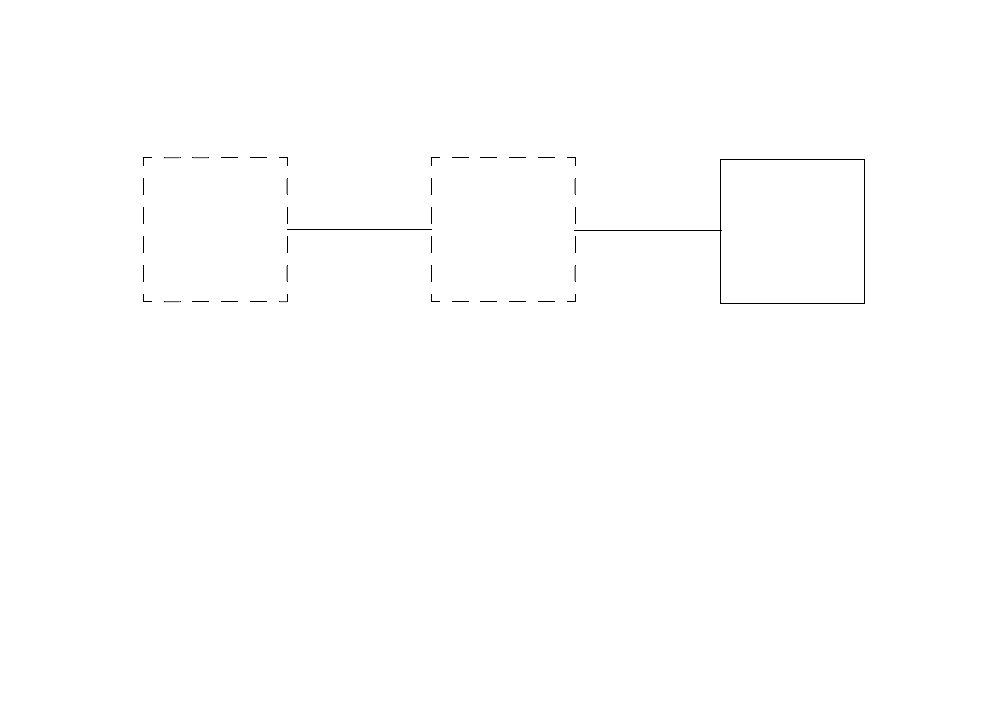
Gold Line VDT Glenayre Document Number: 9110.00164
CALIBRATE FWD/REF PWR Issue 1, Rev. F: 09/03/96
Page: 11-2 Copyright © 1996 Glenayre Print Date: 12/17/96
11.1 CALIBRATE FWD PWR
Note
Output is at cabinet-mounted connector on 36 inch cabinet. On other
cabinets, output is at isolator output.
Refer to following diagram for initial steps of Calibrate Forward Power procedure..
•Press K to unkey transmitter if transmitter is keyed.
•Connect wattmeter and dummy load to transmitter RF output.
•Press K on VDT keyboard to key transmitter.
•Press and hold U on VDT keyboard until wattmeter reads correct wattage if wattmeter
reads below that wattage.
•Press and hold D on VDT keyboard until wattmeter reads correct wattage if wattmeter
reads above that wattage.
•Press Enter on VDT keyboard when the wattmeter reads correct wattage.
•Press N on VDT keyboard if wattmeter does not read correct wattage. Go to step 5.
•Press Y on VDT keyboard if wattmeter does read correct wattage.
Caution
Wattmeter must read exactly correct wattage to
ensure proper metering.
•Menu displays TX CALIBRATED. Press K on VDT keyboard to unkey transmitter.
•Disconnect wattmeter and dummy load; return transmitter to service.
Procedure is complete.
MAIN
MENU
LOCAL*
CALIBRATE
FWD/REF
PWR
CALIBRATE
FWD PWR

Glenayre Document Number: 9110.00164 Gold Line VDT
Issue 1, Rev. F: 09/03/96 CALIBRATE FWD/REF PWR
Print Date: 12/17/96 Copyright © 1996 Glenayre Page: 11-3
11.2 Calibrate Ref Pwr
Note
Output is at cabinet-mounted connector on 36 inch cabinet. On other
cabinets, output is at isolator output. Before continuing, forward power
calibration must have been completed.
Refer to following diagram for initial steps of Calibrate Reflected Power procedure.
•Press Enter to continue.
•Disconnect PA RF output from load at a convenient point.
•Press Enter to continue.
•Automatic reflected power calibration has just occurred.
•Press Enter to continue.
•This procedure is finished.
MAIN
MENU
LOCAL*
CALIBRATE
FWD/REF
PWR
CALIBRATE
REF PWR
Gold Line VDT Glenayre Document Number: 9110.00164
CALIBRATE FWD/REF PWR Issue 1, Rev. F: 09/03/96
Page: 11-4 Copyright © 1996 Glenayre Print Date: 12/17/96

Glenayre Document Number: 9110.00164 Gold Line VDT
Issue 1, Rev. F: 09/03/96 CHANGE MODE
Print Date: 12/17/96 Copyright © 1996 Glenayre Page: 12-1
12 CHANGE MODE
Refer to following diagram for initial steps of Change Mode procedure
.
•Press option to select analog mode if not already selected. Transmitter operating mode
selection status changes to MODE IS CURRENTLY ANALOG.
•Press option to select digital mode A if not already selected. Transmitter operating mode
selection status changes to MODE IS CURRENTLY MODE A.
•Press option to select digital mode B if not already selected. Transmitter operating mode
selection status changes to MODE IS CURRENTLY MODE B.
•Press option to select digital mode C if not already selected. Transmitter operating mode
selection status changes to MODE IS CURRENTLY MODE C.
•Press option to select digital mode D if not already selected. Transmitter operating mode
selection status changes to MODE IS CURRENTLY MODE D.
MAIN
MENU
LOCAL*
CHANGE
MODE
Gold Line VDT Glenayre Document Number: 9110.00164
CHANGE MODE Issue 1, Rev. F: 09/03/96
Page: 12-2 Copyright © 1996 Glenayre Print Date: 12/17/96

Glenayre Document Number: 9110.00164 Gold Line VDT
Issue 1, Rev. F: 09/03/96 CHANGE CHANNEL
Print Date: 12/17/96 Copyright © 1996 Glenayre Page: 13-1
13 CHANGE CHANNEL
Refer to following diagram for initial steps of Change Channel procedure.
•Press option to change channel and status indication to channel one.
•Press option to change channel and status indication to channel two.
•Press option to change channel and status indication to channel three.
•Press option to change channel and status indication to channel four.
•Press option to change channel and status indication to channel five.
•Press option to change channel and status indication to channel six.
•Press option to change channel and status indication to channel seven.
•Press option to change channel and status indication to channel eight.
•Press option to change channel and status indication to channel nine.
•Press option to change channel and status indication to channel ten.
•Press option to change channel and status indication to channel eleven.
•Press option to change channel and status indication to channel twelve.
•Press option to change channel and status indication to channel thirteen.
•Press option to change channel and status indication to channel fourteen.
•Press option to change channel and status indication to channel fifteen.
•Press option to change channel and status indication to channel sixteen.
MAIN
MENU
LOCAL*
CHANGE
CHANNEL
Gold Line VDT Glenayre Document Number: 9110.00164
CHANGE CHANNEL Issue 1, Rev. F: 09/03/96
Page: 13-2 Copyright © 1996 Glenayre Print Date: 12/17/96
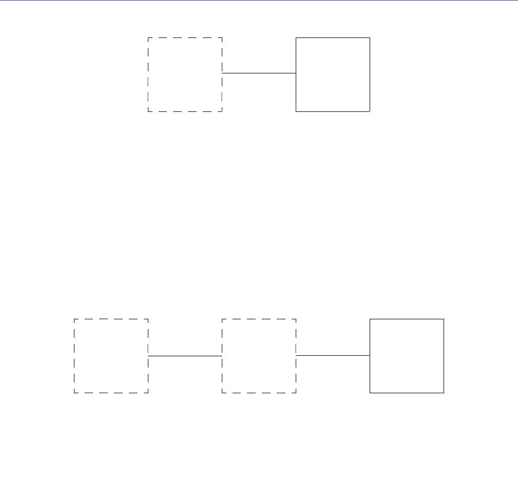
Glenayre Document Number: 9110.00164 Gold Line VDT
Issue 1, Rev. F: 09/03/96 TESTS/UPLOAD
Print Date: 12/17/96 Copyright © 1996 Glenayre Page: 14-1
14 TESTS/UPLOAD
Refer to following diagram for initial steps of Tests/Upload procedure.
•Press option to KEY/UNKEY EXCITER
•Press option to initiate exciter front-panel LEDs test and display menu: LEDS TEST
•N/A
•Press option to RESET EXCITER
•Press option to initiate alarms test to see if alarms are reported correctly: TEST ALARMS
•Press option to UPDATE FIRMWARE
14.1 Key/Unkey Exciter
Refer to following diagram for initial steps of Key/Unkey Exciter procedure.
•Press option to key exciter internal keyline if transmitter is unkeyed. Exciter key state
changes to KEYED. KEY LED on exciter front panel is illuminated. Any exciter keyline
outputs or key reports are activated.
•Press option to unkey exciter internal keyline if exciter is keyed and AGC reference
voltage is low (PA unkeyed). Exciter key state changes to UNKEYED. KEY LED on
exciter front panel is extinguished. Any exciter keyline outputs or key reports are
deactivated.
MAIN
MENU
LOCAL*
TESTS/
UPLOAD
MAIN
MENU
LOCAL*
TESTS/
UPLOAD
KEY/UNKEY
EXCITER
*IN LOCAL CONTROL
MODE ONLY

Gold Line VDT Glenayre Document Number: 9110.00164
TESTS/UPLOAD Issue 1, Rev. F: 09/03/96
Page: 14-2 Copyright © 1996 Glenayre Print Date: 12/17/96
14.2 LEDs Test
Refer to following diagram for initial steps of LEDs Test procedure.
•Observe that front-panel LEDs on exciter light as follows:
All tested LEDs: light green except VSWR which lights red.
FAULT/ALARM: lights red; flashes green; flashes red; returns to green.
REMOTE LOCAL: toggles orange/green; returns to green.
KEY: flashes green; returns to green.
RF OUT/RF LOW: toggles orange/green; toggles orange/red; returns to green.
VSWR: flashes red; returns to red.
DIGITAL/ANALOG: toggles orange/green.
•All tested LEDs: return to original pretest color. Ignore DC POWER and MODULA-
TION/LIMITING LEDs which are not tested during this procedure.
•Return transmitter to service
Test is complete.
MAIN
MENU
LOCAL*
TESTS/
UPLOAD
LEDS
TEST

Glenayre Document Number: 9110.00164 Gold Line VDT
Issue 1, Rev. F: 09/03/96 TESTS/UPLOAD
Print Date: 12/17/96 Copyright © 1996 Glenayre Page: 14-3
14.3 N/A
14.4 Reset Exciter
Select to reset exciter.
14.5 Test Alarms
Refer to following diagram for initial steps of Test Alarms procedure.
•Press option to toggle RF IN fault on/off.
•Press option to toggle PA DC LOW fault on/off.
•Press option to toggle PA SHTDWN fault on/off.
•Press option to toggle ISOLATOR fault on/off
•N/A
•Press option to toggle PA FLT fault on/off.
•Press option to toggle MOD IND fault on/off.
•Press option to toggle TEMP FLT fault on/off
MAIN
MENU
LOCAL*
TESTS/
UPLOAD
TEST
ALARMS

Gold Line VDT Glenayre Document Number: 9110.00164
TESTS/UPLOAD Issue 1, Rev. F: 09/03/96
Page: 14-4 Copyright © 1996 Glenayre Print Date: 12/17/96
14.6 Update Firmware
Refer to following diagram for initial steps of Update Firmware Procedure.
Press enter to continue firmware ugrade.
•Place firmware update diskette in drive A or B.
•Press ALT-F5 to continue firmware update.
•Use filename. Example: a:\upload.asx.
MAIN
MENU
LOCAL*
TESTS/
UPLOAD
UPDATE
FIRMWARE