Glenayre Electronics GL-T8600-CN Base Station User Manual Users manual part 2
Glenayre Electronics Inc Base Station Users manual part 2
Contents
Users manual part 2
Print Date: 12/17/96 Copyright © 1996 Glenayre
Gold Line Power Supplies Issue 1, Rev. D: 02/01/96
Specifications subject to change without notice
Copyright © 1996 Glenayre
All rights reserved. No part of this work may be reproduced or copied in any form or by
any means—graphic, electronic, or mechanical, including photocopying, recording,
taping, or information-retrieval system—without written permission of Glenayre.
Gold Line Power Supplies
USER MANUAL
PN 9110.00159 (old part number=916-8500-003)
REV D
RELEASED
Gold Line Power Supplies Glenayre Document Number: 9110.00159
Document Change Record Issue 1, Rev. D: 02/01/96
Copyright © 1996 Glenayre Print Date: 12/17/96
Document Change Record
Revision: B
Date: 06/17/95
Changes: none, original
Issue: C
Date: 08/21/95
Changes: picture change
Issue: D
Date: 02/01/96
Changes: new format

Glenayre Document Number: 9110.00159 Gold Line Power Supplies
Issue 1, Rev. D: 02/01/96 Table of Contents
Print Date: 12/17/96 Copyright © 1996 Glenayre Page: -i
Table of Contents
1 GENERAL . . . . . . . . . . . . . . . . . . . . . . . . . . . . . . . . . . . . 1-1
1.1 Manual Scope . . . . . . . . . . . . . . . . . . . . . . . . 1-1
1.2 Applicable Documents . . . . . . . . . . . . . . . . . . . . 1-1
1.3 Manual Sections . . . . . . . . . . . . . . . . . . . . . . . 1-2
2 SPECIFICATIONS . . . . . . . . . . . . . . . . . . . . . . . . . . . . . . . . 2-1
3 DESCRIPTION . . . . . . . . . . . . . . . . . . . . . . . . . . . . . . . . . . 3-1
3.1 Introduction . . . . . . . . . . . . . . . . . . . . . . . . . 3-1
3.2 Physical Description . . . . . . . . . . . . . . . . . . . . . 3-1
3.2.1 Mounting Provisions . . . . . . . . . . . . . . . . . . . . . . . 3-1
3.3 Simplified Description . . . . . . . . . . . . . . . . . . . . 3-2
4 INSTALLATION AND SETUP . . . . . . . . . . . . . . . . . . . . . . . . . 4-1
4.1 Precautions and Hazards . . . . . . . . . . . . . . . . . . . . 4-1
4.2 Test Equipment and Tools Required . . . . . . . . . . . . . . . 4-1
4.3 Component and Adjustment Locations . . . . . . . . . . . . . . 4-1
4.4 Installation . . . . . . . . . . . . . . . . . . . . . . . . . 4-1
4.4.1 Inspection . . . . . . . . . . . . . . . . . . . . . . . . . . . . . 4-1
4.4.2 Power Requirement . . . . . . . . . . . . . . . . . . . . . . . . 4-1
4.4.3 Input/Output Connections . . . . . . . . . . . . . . . . . . . . 4-2
4.4.4 Chassis Removal and Reinstallation . . . . . . . . . . . . . . . 4-3
4.4.5 Ac Voltage Change . . . . . . . . . . . . . . . . . . . . . . . . 4-3
4.4.5.1 Dc Voltage Check . . . . . . . . . . . . . . . . . . 4-4
4.5 Ultimate Disposition . . . . . . . . . . . . . . . . . . . . . 4-4
5 OPERATION . . . . . . . . . . . . . . . . . . . . . . . . . . . . . . . . . . . 5-1
5.1 Front-Panel Controls and Indicators . . . . . . . . . . . . . . . 5-1
5.2 Operating Instructions . . . . . . . . . . . . . . . . . . . . . 5-1
6 THEORY OF OPERATION . . . . . . . . . . . . . . . . . . . . . . . . . . . 6-1
6.1 Chassis Components . . . . . . . . . . . . . . . . . . . . . 6-1
6.2 Voltage Regulator Assembly . . . . . . . . . . . . . . . . . . 6-1
7 MAINTENANCE . . . . . . . . . . . . . . . . . . . . . . . . . . . . . . . . . 7-1
7.1 Location of Maintenance Procedures . . . . . . . . . . . . . . . 7-1
8 CHECKOUT AND TROUBLESHOOTING . . . . . . . . . . . . . . . . . . 8-1
8.0.1 Test Equipment and Tools Required . . . . . . . . . . . . . . . 8-1
8.0.2 Precautions . . . . . . . . . . . . . . . . . . . . . . . . . . . . 8-1
8.0.3 Resonator Capacitor Check . . . . . . . . . . . . . . . . . . . 8-1
8.0.4 Transformer Check . . . . . . . . . . . . . . . . . . . . . . . . 8-1
Gold Line Power Supplies Glenayre Document Number: 9110.00159
Table of Contents Issue 1, Rev. D: 02/01/96
Page: -ii Copyright © 1996 Glenayre Print Date: 12/17/96
8.0.5 Diode Check . . . . . . . . . . . . . . . . . . . . . . . . . . . 8-1
9 REMOVAL AND REINSTALLATION . . . . . . . . . . . . . . . . . . . . 9-1
9.1 Precautions and Hazards . . . . . . . . . . . . . . . . . . . 9-1
9.2 Test Equipment and Tools Required . . . . . . . . . . . . . . . 9-1
9.3 Ac Voltage Change . . . . . . . . . . . . . . . . . . . . . 9-1
9.4 Component Locations . . . . . . . . . . . . . . . . . . . . 9-1
9.5 Chassis Removal and Reinstallation . . . . . . . . . . . . . . . 9-1
9.5.1 Removing Chassis from Rack . . . . . . . . . . . . . . . . . . 9-2
9.5.2 Reinstalling Power Supply into Rack . . . . . . . . . . . . . . 9-2
9.6 Removing and Reinstalling the 13.5-Volt Regulator . . . . . . . . 9-2
9.6.1 Removing 13.5-Volt Regulator . . . . . . . . . . . . . . . . . 9-3
9.6.2 Reinstalling 13.5-Volt Regulator . . . . . . . . . . . . . . . . 9-3
10 OPTION . . . . . . . . . . . . . . . . . . . . . . . . . . . . . . . . . . . . 10-1

Glenayre Document Number: 9110.00159 Gold Line Power Supplies
Issue 1, Rev. D: 02/01/96 List of Figures
Print Date: 12/17/96 Copyright © 1996 Glenayre Page: -iii
List of Figures
Figure 3-1 Front View of Gold Line 50A Power Supply . . . . . . . . . . . . . . 3-3
Figure 3-2 Top View of Gold Line 50A Power Supply . . . . . . . . . . . . . . . 3-4
Figure 3-3 Front View of Gold Line 90-A Power Supply . . . . . . . . . . . . . . 3-5
Figure 3-4 Top View of Gold Line 90-A Power Supply . . . . . . . . . . . . . . . 3-6
Figure 4-1 Ac Jumpering 100 Vac Nominal . . . . . . . . . . . . . . . . . . . . . 4-5
Figure 4-2 Ac Jumpering 115 Vac Nominal . . . . . . . . . . . . . . . . . . . . . 4-6
Figure 4-3 Ac Jumpering 200 Vac Nominal . . . . . . . . . . . . . . . . . . . . . 4-7
Figure 4-4 Ac Jumpering 230 Vac Nominal . . . . . . . . . . . . . . . . . . . . . 4-8
Figure 5-1 Gold Line Power Supply Front-Panel Controls and Indicators . . . . . 5-2
Figure 6-1 50A Power Supply Functional Diagram . . . . . . . . . . . . . . . . . 6-2
Figure 6-2 90A Power Supply Functional Diagram . . . . . . . . . . . . . . . . . 6-3
Figure 6-3 Power Supply 13.5V Regulator Assembly/Functional Diagram . . . . . 6-4
Figure 7-1 Gold Line 50A Power Supply Assembly 265-0082-012 . . . . . . . . . 7-2
Figure 7-2 Gold Line 50A Power Supply Assembly 265-0082-012 . . . . . . . . . 7-4
Figure 7-2 Gold Line 90A Power Supply Assembly 265-0082-006 . . . . . . . . . 7-5
Figure 9-1 Power Supply Removal and Reinstallation from/into rack . . . . . . . 9-4
Figure 9-2 13.5-Volt Regulator Board Removal and Reinstallation . . . . . . . . . 9-5
Figure 10-1 Gold Line 50/90A DC Only Power Supply Assembly . . . . . . . . . 10-1
Figure 10-2 Gold Line 50A DC-Only Power Supply Functional Diagram . . . . . 10-2
Figure 10-3 Gold Line 90A DC-Only Power Supply Functional Diagram . . . . . 10-3
Gold Line Power Supplies Glenayre Document Number: 9110.00159
List of Figures Issue 1, Rev. D: 02/01/96
Page: -iv Copyright © 1996 Glenayre Print Date: 12/17/96

Glenayre Document Number: 9110.00159 Gold Line Power Supplies
Issue 1, Rev. D: 02/01/96 List of Tables
Print Date: 12/17/96 Copyright © 1996 Glenayre Page: -v
List of Tables
Table 1-1 Applicable Documents . . . . . . . . . . . . . . . . . . . . . . . . . 1-1
Table 1-2 Manual Contents . . . . . . . . . . . . . . . . . . . . . . . . . . . . . 1-2
Table 2-1 Gold Line Power Supplies Specifications . . . . . . . . . . . . . . . . 2-1
Table 3-1 Gold Line Power Supply Options . . . . . . . . . . . . . . . . . . . . 3-1
Table 4-1 Input/Output Connections . . . . . . . . . . . . . . . . . . . . . . . . 4-2
Table 4-2 Transformer Connection and Jumpers . . . . . . . . . . . . . . . . . . 4-3
Gold Line Power Supplies Glenayre Document Number: 9110.00159
List of Tables Issue 1, Rev. D: 02/01/96
Page: -vi Copyright © 1996 Glenayre Print Date: 12/17/96

Glenayre Document Number: 9110.00159 Gold Line Power Supplies
Issue 1, Rev. D: 02/01/96 GENERAL
Print Date: 12/17/96 Copyright © 1996 Glenayre Page: 1-1
1 GENERAL
1.1 Manual Scope
This manual is intended for use as part of a paging-transmitter system manual. It contains
information concerning the overall operation of the Gold Line 50 and 90-ampere power
supplies.
This manual covers the power supplies configured with no options.
1.2 Applicable Documents
Table 1-1, Applicable Documents, lists and briefly describes related part numbers which
may be required to document the set of user equipment.
Table 1-1 Applicable Documents
document part number description
GL-T8500/8600 VDT
manual
9110.00164 describes 250/500-W, 900-MHz Gold Line
VDT software with QT-1000 interface
GL-T8500/8600 system
manual
9110.00163 describes transmitter equipment and
interconnections with QT-1000 control
equipment
GL-T8500/8600 exciter
/ PA control manual
9110.00172 describes exciter and QT-1000 interface
GL-T8500 power
amplifier manual
9110.00160 describes 250-W, 900 MHz Gold Line
power amplifier
GL-T8600 power
amplifier manual
9110.00162 describes 500-W, 900 MHz Gold Line
power amplifier
GL-T8500/T8600 power
supply manual
9110.00159 this manual

Gold Line Power Supplies Glenayre Document Number: 9110.00159
GENERAL Issue 1, Rev. D: 02/01/96
Page: 1-2 Copyright © 1996 Glenayre Print Date: 12/17/96
1.3 Manual Sections
Table 1-2, Manual Contents, lists manual sections and their contents. Refer to the table of
contents for additional detail.
Table 1-2 Manual Contents
section no.
and title contents
1 General this section
2 Specifications list of power supply specifications. Also see specifications in system
manual.
3 Descriptions listing of options and assemblies covered, simplified electrical
description, physical description, simplified block theory of
operation
4 Installation and
Setup
power supply installation, setup, and lists of connections
5 Operation listing, description, and location of operator controls and indicators
6 Theory of Oper-
ation
assembly-level description of power supply operation
7 Maintenance power supply maintenance (covered in system manual)
8 Checkout and
Troubleshooting
power supply checkout and troubleshooting (covered in system
manual)
9 Removal and
Reinstallation
procedures for removing and reinstalling power supply and power
supply assemblies

Glenayre Document Number: 9110.00159 Gold Line Power Supplies
Issue 1, Rev. D: 02/01/96 SPECIFICATIONS
Print Date: 12/17/96 Copyright © 1996 Glenayre Page: 2-1
2 SPECIFICATIONS
Table 2-1 lists specifications. Also refer to the specifications in the system manual.
Table 2-1 Gold Line Power Supplies Specifications
characteristic condition specification
ac input voltage (Vac)
GL-T8500 transmitter only
GL-T8500 and GL-T8600
transmitter
100-volt primary
tap
85-115
115-volt primary
tap
98-132
200-volt primary
tap
170-230
230-volt primary
tap
196-264
ac input frequency (Hz) standard optional 60
50
power consumption (A)
GL-T8500 tx only
GL-T8500 and GL-T8600
transmitter
100-volt or 115-
volt primary tap
12-17
200-volt or 230-
volt primary tap
12-17
power output 25-Vdc outputs 22-28 Vdc at 50 A/90A
total, some outputs
fused
13.5-Vdc output 12.8-14.2 Vdc at 5 A,
current-limited
weight (approx.) GL-T8500
GL-T8600
60 lb (27 kg)
70 lb (32 kg)
dimensions height 8.75 in (22.5 cm)
depth 9.25 in (23.5 cm)
width 19 in (48.5 cm)
Gold Line Power Supplies Glenayre Document Number: 9110.00159
SPECIFICATIONS Issue 1, Rev. D: 02/01/96
Page: 2-2 Copyright © 1996 Glenayre Print Date: 12/17/96

Glenayre Document Number: 9110.00159 Gold Line Power Supplies
Issue 1, Rev. D: 02/01/96 DESCRIPTION
Print Date: 12/17/96 Copyright © 1996 Glenayre Page: 3-1
3 DESCRIPTION
3.1 Introduction
The Gold Line 50-A and 90-A power supplies are part of a radio paging transmitter. The
50-A version is used in the GL-T8500 transmitter; the 90-A version is used in the GL-
T8600 transmitter. The supplies provide power to other assemblies within the rack,
including cooling fans.
Refer to Table 3-1 Gold Line Power Supply Options for more information.
3.2 Physical Description
The supply chassis must accommodate more than one type of equipment rack. Accordingly,
the assembly may vary slightly for proper cooling and mounting requirements. Weight
varies with supply configuration. Also refer to Table 2-1. Figure 3-1, Front View of Gold
Line 50-A Power Supply shows the front of the power supply, and Figure 3-2, Top View
of Gold Line 50A Power Supply shows a view of the power supply from the top.
3.2.1 Mounting Provisions
The power supply is mounted in a standard 19-inch rack. Some rack cabinets do not have
equipment access from the back; others do. The steel supply chassis has no top or sides.
The protective front cover attaches to the front rail of the rack cabinet. The chassis is folded
on the bottom to allow it to slide between the rack-cabinet floor and two floor-mounted
bars. The chassis is held in place with two bolts that attach to the rack cabinet through the
lower front edge of the chassis. The supply is mounted at the bottom of the equipment rack
in all single-transmitter configurations.
The supply requires little cabinet space. Refer to Figure 3-1, Front View of Gold Line
50-A Power Supply for detail. The front panel of five RUs (8.75 in) in height contains a
circuit breaker and fuses. Figure 5-1, Gold Line 50-A Power Supply Front-Panel
Controls and Indicators shows and describes their functions.
Table 3-1 Gold Line Power Supply Options
item condition transformer
90 A power supply 60 Hz 6401.00019
90 A power supply 50 Hz 6401.00018
50 A power supply 60 Hz 6401.00020
50 A power supply 50 Hz 6401.00017
Gold Line Power Supplies Glenayre Document Number: 9110.00159
DESCRIPTION Issue 1, Rev. D: 02/01/96
Page: 3-2 Copyright © 1996 Glenayre Print Date: 12/17/96
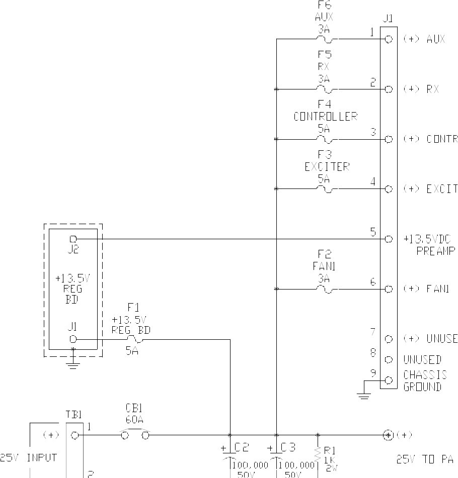
3.3 Simplified Description
Ac power flows to power transformer T1; circuit breaker CB1 provides protection against
excess current. The rectified and filtered 25-volt output is supplied to other transmitter
assemblies. The 25-volt output also goes, via fuse F1, to the 13.5-volt regulator board,
which provides 13.5 volts for use by the transmitter.
Glenayre Document Number: 9110.00159 Gold Line Power Supplies
Issue 1, Rev. D: 02/01/96 DESCRIPTION
Print Date: 12/17/96 Copyright © 1996 Glenayre Page: 3-3
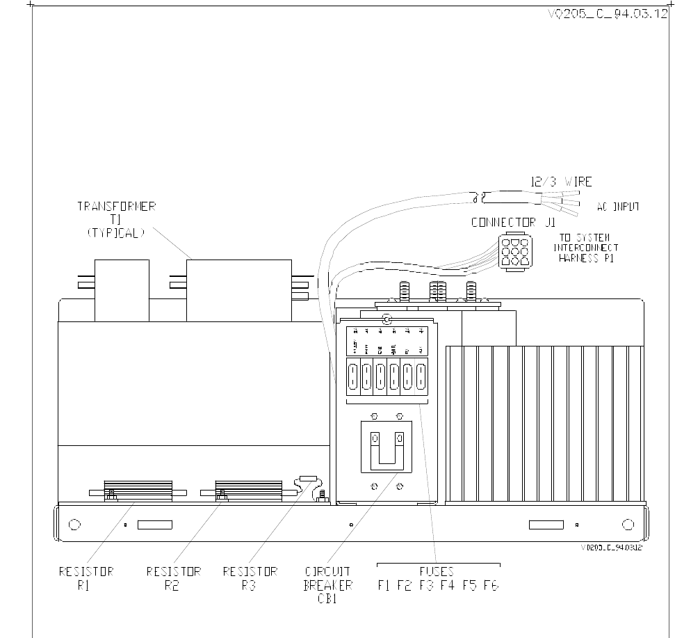
Figure 3-1 Front View of Gold Line 50-A Power Supply
Gold Line Power Supplies Glenayre Document Number: 9110.00159
DESCRIPTION Issue 1, Rev. D: 02/01/96
Page: 3-4 Copyright © 1996 Glenayre Print Date: 12/17/96
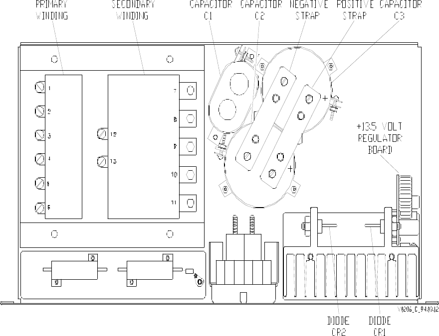
Figure 3-2 Top View of Gold Line 50A Power Supply
Glenayre Document Number: 9110.00159 Gold Line Power Supplies
Issue 1, Rev. D: 02/01/96 DESCRIPTION
Print Date: 12/17/96 Copyright © 1996 Glenayre Page: 3-5
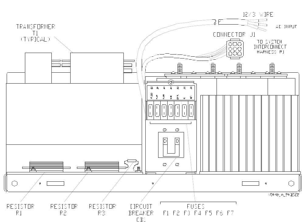
Figure 3-3 Front View of Gold Line 90-A Power Supply
Gold Line Power Supplies Glenayre Document Number: 9110.00159
DESCRIPTION Issue 1, Rev. D: 02/01/96
Page: 3-6 Copyright © 1996 Glenayre Print Date: 12/17/96
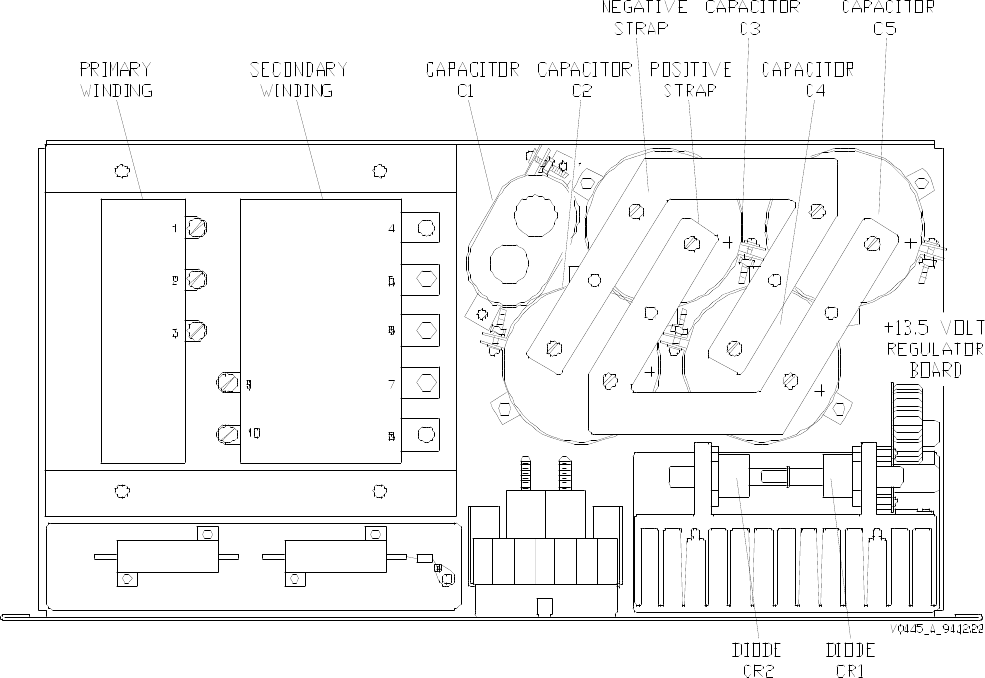
Figure 3-4 Top View of Gold Line 90-A Power Supply

Glenayre Document Number: 9110.00159 Gold Line Power Supplies
Issue 1, Rev. D: 02/01/96 INSTALLATION AND SETUP
Print Date: 12/17/96 Copyright © 1996 Glenayre Page: 4-1
4 INSTALLATION AND SETUP
4.1 Precautions and Hazards
DANGER
The power supply chassis is not protected by
interlocks. Disconnect ac power before removing
any covers.
DANGER
The power transformer is heavy. Follow
precautions for heavy lifting.
4.2 Test Equipment and Tools Required
Common hand tools are required for assembly and disassembly. An RFI-immune voltmeter
is required for voltage measurement. Also refer to the system manual.
4.3 Component and Adjustment Locations
Figure 5-1, Gold Line 50-A Power Supply Front-Panel Controls and Indicators, shows the
locations of circuit breaker CB1 and the fuses. The only user-setup option is the power-
transformer-input-voltage jumpering.
4.4 Installation
4.4.1 Inspection
Refer to the system manual for inspection information.
4.4.2 Power Requirement
Refer to Section 2 for power specifications.

Gold Line Power Supplies Glenayre Document Number: 9110.00159
INSTALLATION AND SETUP Issue 1, Rev. D: 02/01/96
Page: 4-2 Copyright © 1996 Glenayre Print Date: 12/17/96
4.4.3 Input/Output Connections
Table 4-1, Input/Output Connections, shows the connections and functions of I/O connec-
tions for the power supply. The power transformer input must be jumpered for the expected
ac input voltage. Refer to the procedure in this paragraph.
Power supply output connections are made on the filter capacitor assembly inside the
supply. Dc output is cabled directly to the power amplifier chassis. Dc output also goes to
other equipment via a connector and cable. Ac input connections are made directly to
circuit breaker CB1.
Table 4-2, Transformer Connection and Jumpers, shows the connections and jumper
settings for the power supply. The power transformer input must be jumpered for the
expected ac input voltage.
Table 4-1 Input/Output Connections
connection schematic label and function
CB1-A L. one (black wire) side of ac mains input (goes to TB1-3*)
CB1-B L. other (white wire) side of ac mains input (goes to TB1-2*)
ground stud E. ground (green wire*) conductor for ac mains (goes to TB1-1)
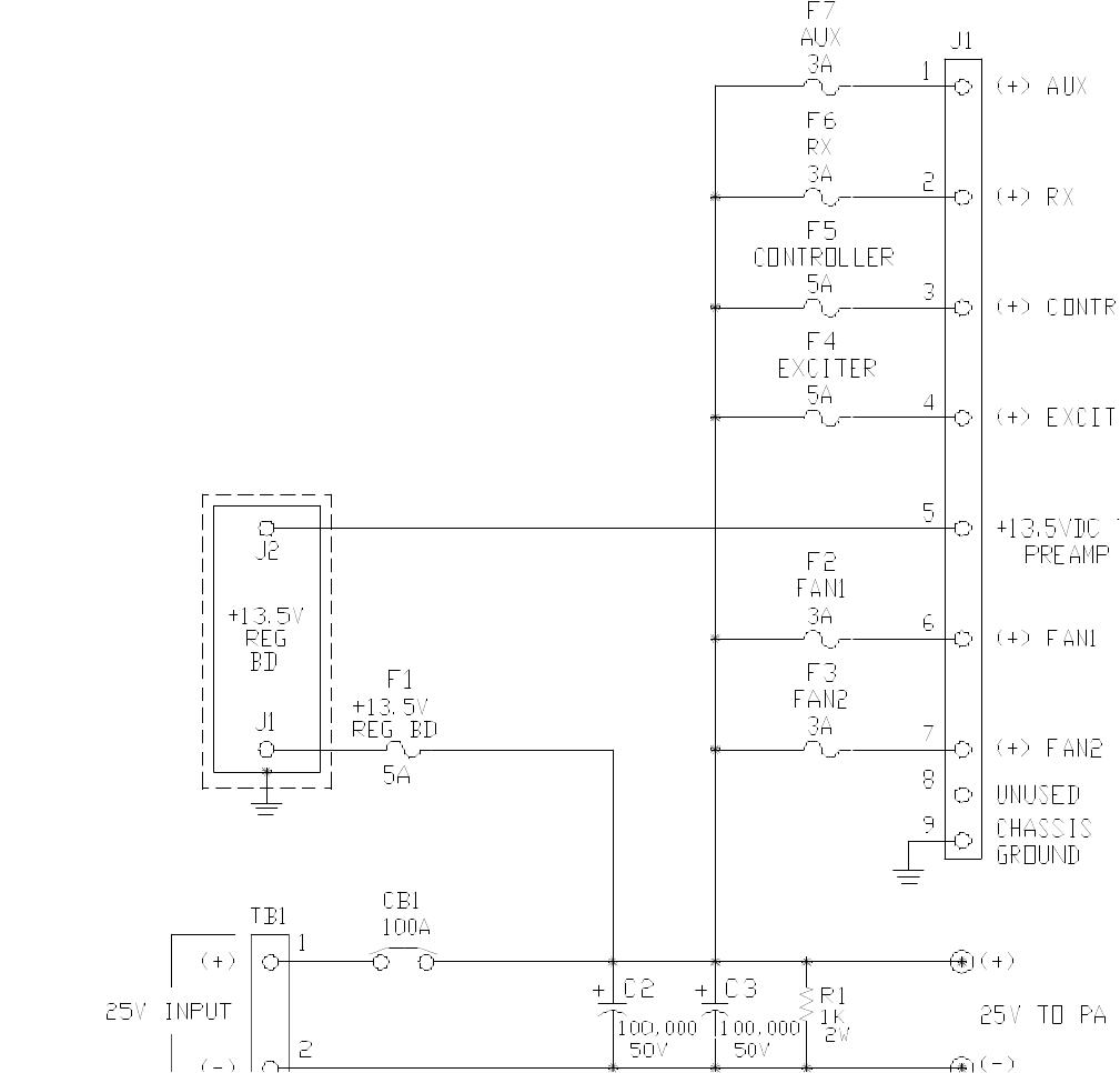
J1-1 + AUX. fuses 25 Vdc for auxiliary equipment
J1-2 +RX. fused 25 Vdc for receiver
J1-3 +CONTROLLER. fused 25 Vdc for transmitter controller
J1-4 +EXCITER. fused 25 Vdc for exciter
J1-5 +13.5VDC TO PREAMP. 13.5 Vdc to preamplifier
J1-6 +FAN 1. fused 25 Vdc to fan1
J1-7 +FAN 2. fused 25 Vdc to fan2
J1-8, -9 unused
filter cap
straps
+. 25-Vdc to PA
-. 25 Vdc dc return from PA (See Figure 3-2 and Figure 3-4.)
__________
*terminal strip on rear-rail-mounted air plenum (22” deep cabinet or on side of 10”
deep cabinet)

Glenayre Document Number: 9110.00159 Gold Line Power Supplies
Issue 1, Rev. D: 02/01/96 INSTALLATION AND SETUP
Print Date: 12/17/96 Copyright © 1996 Glenayre Page: 4-3
4.4.4 Chassis Removal and Reinstallation
Refer to paragraph 9.5 for a procedure.
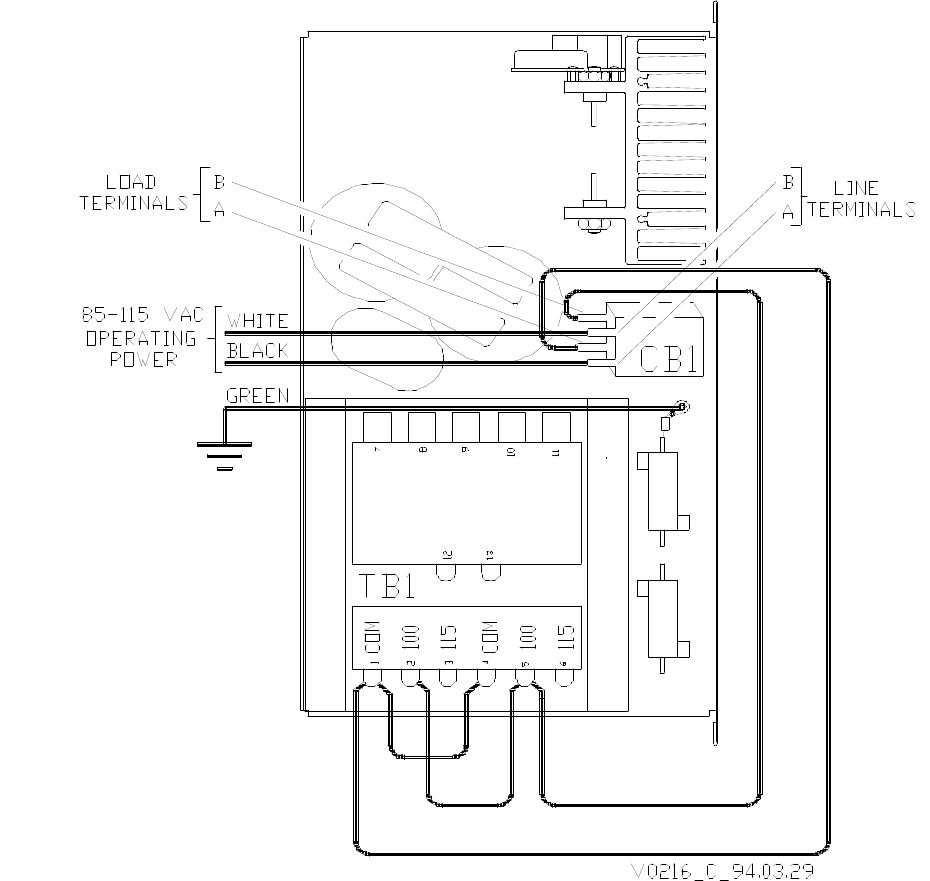
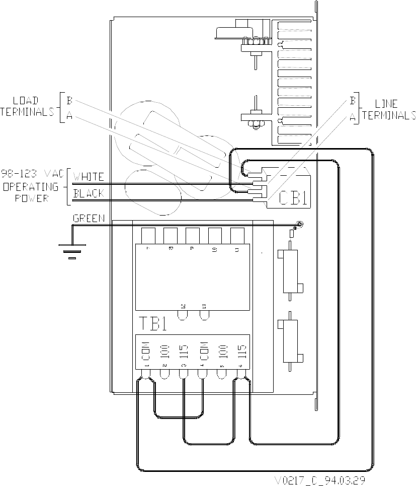
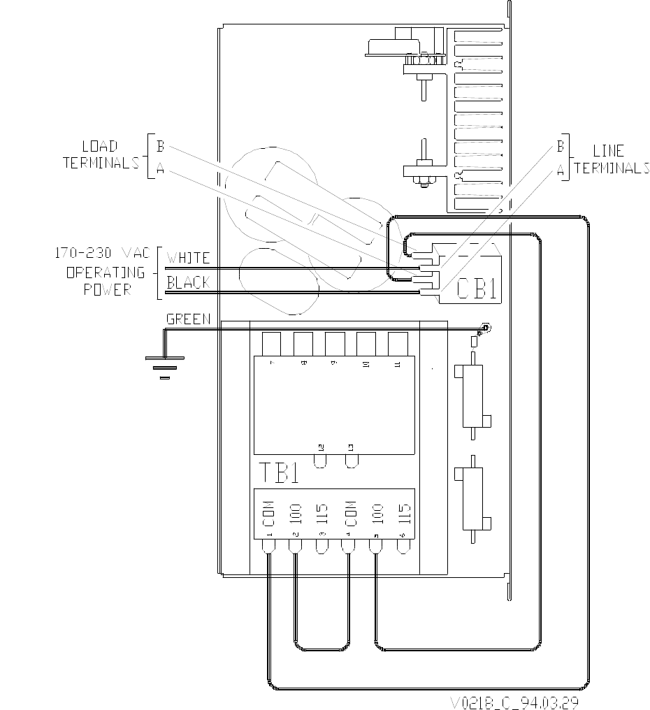
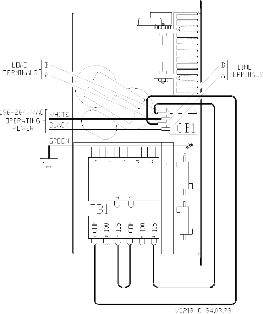
4.4.5 Ac Voltage Change
This procedure requires only common hand tools.
Note
Any added jumper must be of adequate wire size to accommodate current
requirements. Be certain that all transformer connections are tight.
1. Disconnect ac power and remove power supply cover.
2. Remove supply chassis from rack.
3. Locate power transformer T1; identify primary terminals.
4. Refer to
Figure 4-1, Ac Jumpering 100 Vac Nominal,
Figure 4-2, Ac Jumpering 115 Vac Nominal,
Figure 4-3, Ac Jumpering 200 Vac Nominal,
Figure 4-4, Ac Jumpering 230 Vac Nominal,
to configure transformer. Place jumpers for expected line voltage.
5. Reinstall supply chassis into rack; be sure no tools or hardware have been left inside
the power supply.
6. Replace supply cover.
Table 4-2 Transformer Connection and Jumpers
50A version power supply
voltage input jumpers
100V 1 and 5 1 and 4
2 and 5
115V 1 and 6 1 and 4
3 and 6
200 1 and 5 2 and 4
230 1 and 6 3 and 4
90A version power supply
voltage input jumpers
200 1 and 2 none
230 1 and 3 none

Gold Line Power Supplies Glenayre Document Number: 9110.00159
INSTALLATION AND SETUP Issue 1, Rev. D: 02/01/96
Page: 4-4 Copyright © 1996 Glenayre Print Date: 12/17/96
4.4.5.1 Dc Voltage Check
Perform the following steps to check power supply output voltage:
1. With transmitter unkeyed, check voltage at external interface on rack cabinet. Dc
meter reading should be about 26 Vdc.
2. With transmitter keyed (at rated output), check voltage at external interface. Dc meter
reading should be about 24 Vdc
4.5 Ultimate Disposition
Caution
This equipment may contain hazardous materials.
Check with the local EPA or other environmental
authority before disposing of this equipment.
Glenayre Document Number: 9110.00159 Gold Line Power Supplies
Issue 1, Rev. D: 02/01/96 INSTALLATION AND SETUP
Print Date: 12/17/96 Copyright © 1996 Glenayre Page: 4-5
v0216.hgl
Figure 4-1 Ac Jumpering 100 Vac Nominal
Gold Line Power Supplies Glenayre Document Number: 9110.00159
INSTALLATION AND SETUP Issue 1, Rev. D: 02/01/96
Page: 4-6 Copyright © 1996 Glenayre Print Date: 12/17/96
v0217.hgl
Figure 4-2 Ac Jumpering 115 Vac Nominal
Glenayre Document Number: 9110.00159 Gold Line Power Supplies
Issue 1, Rev. D: 02/01/96 INSTALLATION AND SETUP
Print Date: 12/17/96 Copyright © 1996 Glenayre Page: 4-7
v0218.hgl
Figure 4-3 Ac Jumpering 200 Vac Nominal
Gold Line Power Supplies Glenayre Document Number: 9110.00159
INSTALLATION AND SETUP Issue 1, Rev. D: 02/01/96
Page: 4-8 Copyright © 1996 Glenayre Print Date: 12/17/96
v0219.hgl
Figure 4-4 Ac Jumpering 230 Vac Nominal

Glenayre Document Number: 9110.00159 Gold Line Power Supplies
Issue 1, Rev. D: 02/01/96 OPERATION
Print Date: 12/17/96 Copyright © 1996 Glenayre Page: 5-1
5 OPERATION
5.1 Front-Panel Controls and Indicators
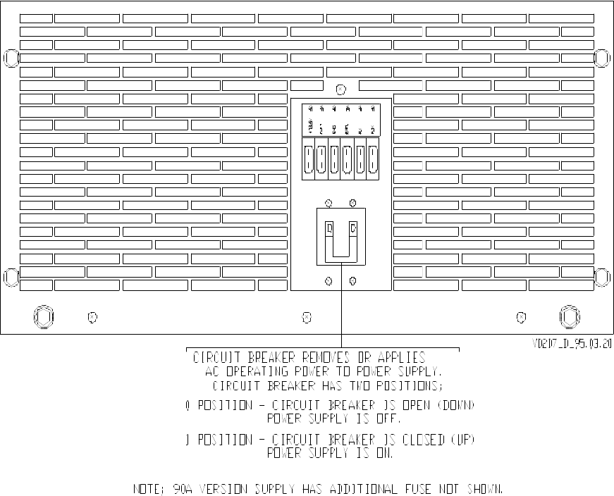
Figure 5-1, Gold Line 50-A Power Supply Front-Panel Controls and Indicators
shows a view of the front panel, with a description of the operation of the circuit breaker.
The function and ratings of fuses are clearly labelled on the equipment. Note that the fuses
are visible from the front panel. In most cases a blown fuse is obvious by visual inspection.
Note their condition when troubleshooting the equipment.
5.2 Operating Instructions
The power supply operates in an unattended manner during normal system operation. Use
the circuit breaker and fuses when it is necesary to perform maintenance or troubleshooting.
Set the circuit breaker to up position to turn on power supply. Set the circuit breaker to
down position to turn off power supply.
Gold Line Power Supplies Glenayre Document Number: 9110.00159
OPERATION Issue 1, Rev. D: 02/01/96
Page: 5-2 Copyright © 1996 Glenayre Print Date: 12/17/96
v0207.hgl
Figure 5-1 Gold Line 50-A Power Supply Front-Panel Controls and Indicators

Glenayre Document Number: 9110.00159 Gold Line Power Supplies
Issue 1, Rev. D: 02/01/96 THEORY OF OPERATION
Print Date: 12/17/96 Copyright © 1996 Glenayre Page: 6-1
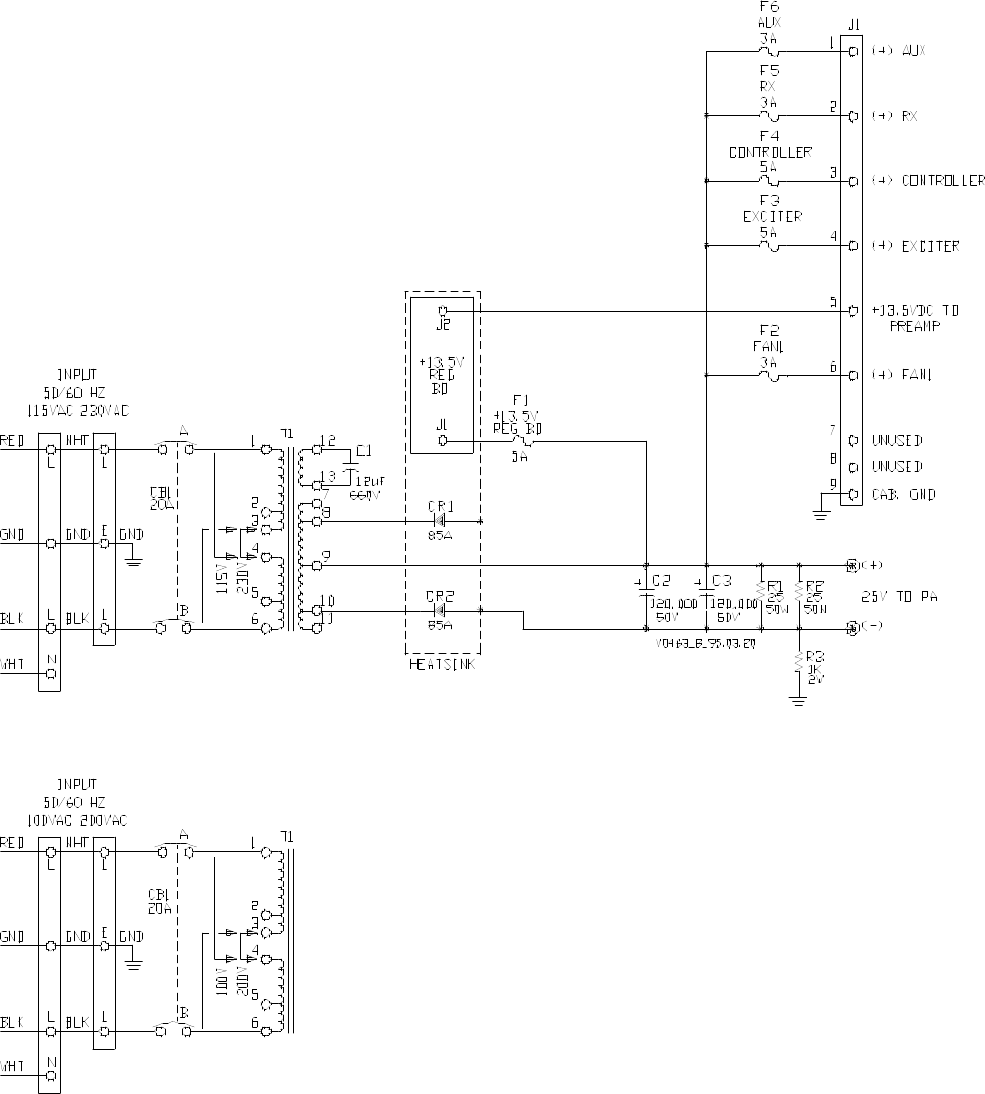
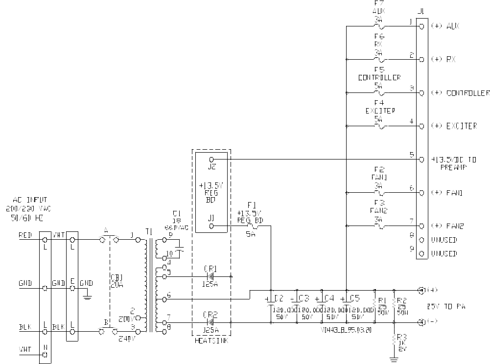
6 THEORY OF OPERATION
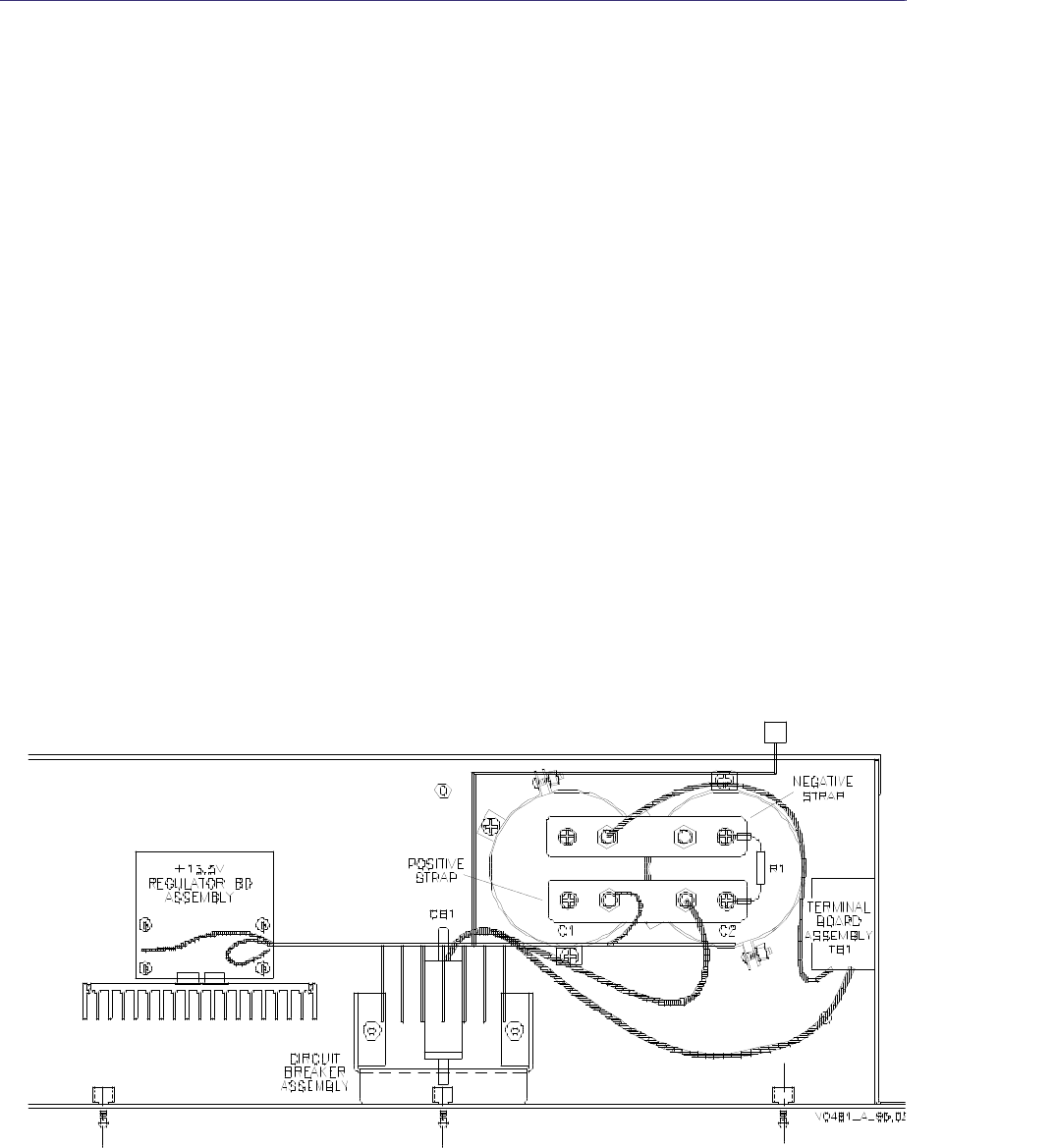
6.1 Chassis Components
Refer to Figure 6-1 and Figure 6-2.
Ferroresonant transformer T1 and resonating capacitor C1 act as a reservoir to allow a
constant voltage output despite changing load conditions as long as a constant voltage is
applied to the input. It is electrically protected by circuit breaker CB1. There are taps on the
primary of the power transformer to allow various ranges of input voltage.
Output is rectified by CR1 and CR2, and filtered by C2, C3, and C4, and C5 to provide a
filtered, stable dc output. Dc output for the PA is cabled directly from the filter capacitor
assembly to terminals mounted on the side of the equipment rack. Dc for the exciter,
receiver, controller, fans, and auxiliary equipment is routed through plug J1.
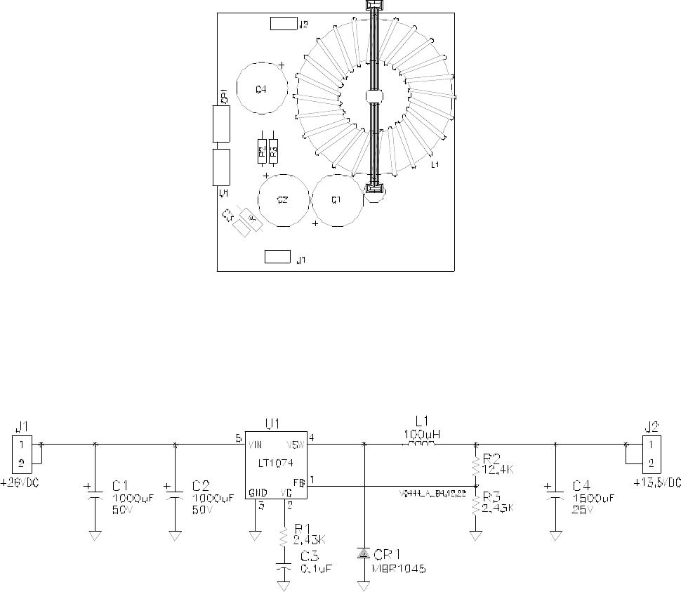
6.2 Voltage Regulator Assembly
Refer to Figure 6-3.
The 13.5-volt output of voltage regulator IC U1 is set by the values of R1 through R3. Asso-
ciated components filter and protect the assembly from damage due to electrical transients.
Gold Line Power Supplies Glenayre Document Number: 9110.00159
THEORY OF OPERATION Issue 1, Rev. D: 02/01/96
Page: 6-2 Copyright © 1996 Glenayre Print Date: 12/17/96
Figure 6-1 50A Power Supply Functional Diagram
Glenayre Document Number: 9110.00159 Gold Line Power Supplies
Issue 1, Rev. D: 02/01/96 THEORY OF OPERATION
Print Date: 12/17/96 Copyright © 1996 Glenayre Page: 6-3
Figure 6-2 90A Power Supply Functional Diagram
Gold Line Power Supplies Glenayre Document Number: 9110.00159
THEORY OF OPERATION Issue 1, Rev. D: 02/01/96
Page: 6-4 Copyright © 1996 Glenayre Print Date: 12/17/96
Figure 6-3 Power Supply 13.5V Regulator Assembly/Functional Diagram

Glenayre Document Number: 9110.00159 Gold Line Power Supplies
Issue 1, Rev. D: 02/01/96 MAINTENANCE
Print Date: 12/17/96 Copyright © 1996 Glenayre Page: 7-1
7 MAINTENANCE
7.1 Location of Maintenance Procedures
Most maintenance of electrical assemblies is done via the VT100 interface. Refer to the
system and menu manuals. No maintenance procedures are performed on a regular
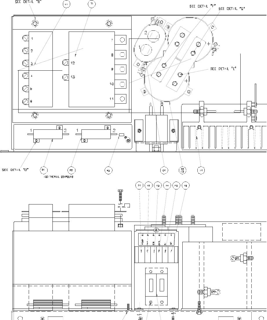
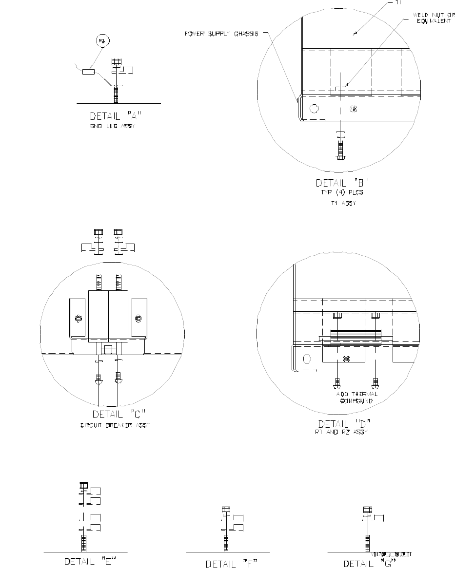
schedule. See section 8 of this manual for more information. Refer to Figure 7-1, Gold
Line 50A Power Supply Assembly 265-0082-012 for additional information.
Gold Line Power Supplies Glenayre Document Number: 9110.00159
MAINTENANCE Issue 1, Rev. D: 02/01/96
Page: 7-2 Copyright © 1996 Glenayre Print Date: 12/17/96
v0479l.hgl
Figure 7-1 Gold Line 50A Power Supply Assembly 265-0082-012
Glenayre Document Number: 9110.00159 Gold Line Power Supplies
Issue 1, Rev. D: 02/01/96 MAINTENANCE
Print Date: 12/17/96 Copyright © 1996 Glenayre Page: 7-3
v0479r.hgl
Figure 7-1 Gold Line 50A Power Supply Assembly 265-0082-012
Gold Line Power Supplies Glenayre Document Number: 9110.00159
MAINTENANCE Issue 1, Rev. D: 02/01/96
Page: 7-4 Copyright © 1996 Glenayre Print Date: 12/17/96
v0480l.hgl
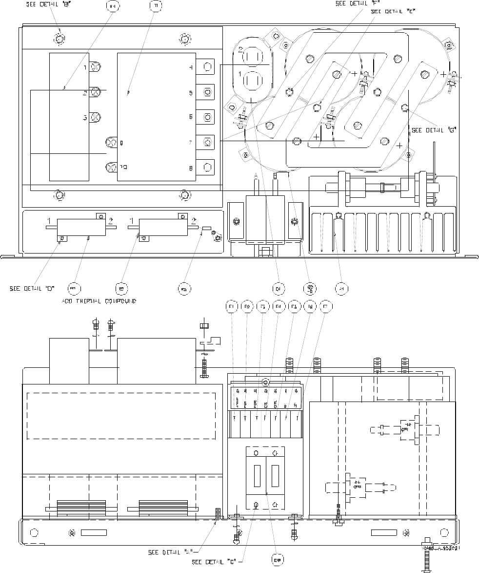
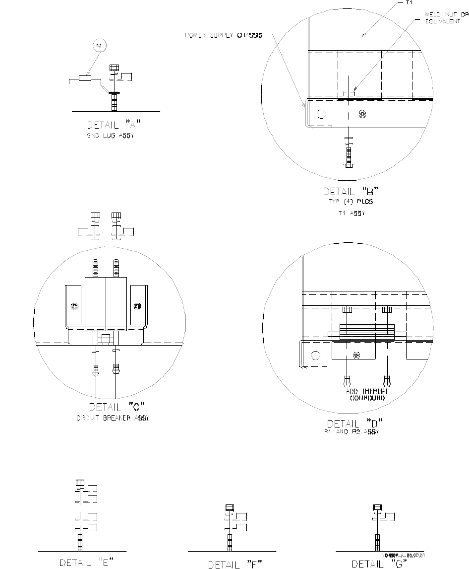
Figure 7-2 Gold Line 90A Power Supply Assembly 265-0082-006
Glenayre Document Number: 9110.00159 Gold Line Power Supplies
Issue 1, Rev. D: 02/01/96 MAINTENANCE
Print Date: 12/17/96 Copyright © 1996 Glenayre Page: 7-5
v0480r.hgl
Figure 7-2 Gold Line 90A Power Supply Assembly 265-0082-006
Gold Line Power Supplies Glenayre Document Number: 9110.00159
MAINTENANCE Issue 1, Rev. D: 02/01/96
Page: 7-6 Copyright © 1996 Glenayre Print Date: 12/17/96

Glenayre Document Number: 9110.00159 Gold Line Power Supplies
Issue 1, Rev. D: 02/01/96 CHECKOUT AND TROUBLESHOOTING
Print Date: 12/17/96 Copyright © 1996 Glenayre Page: 8-1
8 CHECKOUT AND TROUBLESHOOTING
8.0.1 Test Equipment and Tools Required
Common hand tools are required for assembly and disassembly. An RFI-immune voltmeter
is required to measure dc voltages.
8.0.2 Precautions
Follow all danger advisories in paragraph 9.1, as ac power is applied to equipment during
some tests. Only qualified technicians should perform these service items.
8.0.3 Resonator Capacitor Check
With main power applied, connect a dc meter across the supply dc output. Level should be
24-27 Vdc. .
This check is complete.
8.0.4 Transformer Check
With ac input power applied, connect an ac meter across the secondary winding of the
transformer.
Approximately twice supply voltage (50 Vac) should be present.
This check is complete.
8.0.5 Diode Check
With power off, disconnect each diode from the heat sink.
Check with ohmmeter in diode-checking mode from each diode anode to the heat sink;
normal dc conduction should be present from each one.
This check is complete.
Gold Line Power Supplies Glenayre Document Number: 9110.00159
CHECKOUT AND TROUBLESHOOTING Issue 1, Rev. D: 02/01/96
Page: 8-2 Copyright © 1996 Glenayre Print Date: 12/17/96

Glenayre Document Number: 9110.00159 Gold Line Power Supplies
Issue 1, Rev. D: 02/01/96 REMOVAL AND REINSTALLATION
Print Date: 12/17/96 Copyright © 1996 Glenayre Page: 9-1
9 REMOVAL AND REINSTALLATION
9.1 Precautions and Hazards
DANGER
The power supply chassis is not protected by
interlocks. Disconnect ac power before removing
any covers.
DANGER
The power transformer is heavy. Follow
precautions for heavy lifting.
9.2 Test Equipment and Tools Required
Common hand tools are required for assembly and disassembly. An RFI-immune voltmeter
is required for voltage measurement.
9.3 Ac Voltage Change
If the power supply or power transformer is replaced, the expected input voltage must be
set before ac power is applied. Refer to the installation in Section 4.
9.4 Component Locations
Regarding component locations in the 50A supply, see Figure 3-1, Figure 3-2, and
Figure 7-1.
Regarding component locations in the 90A supply, see Figure 3-3, Figure 3-4, and
Figure 7-2.
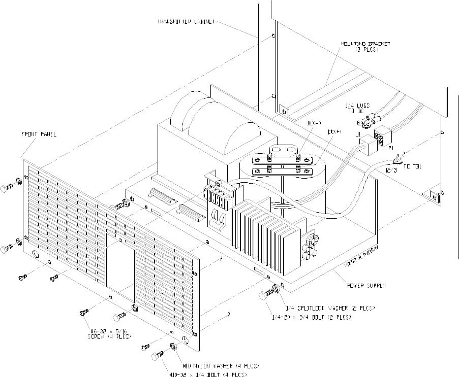
9.5 Chassis Removal and Reinstallation
Heed all danger references at the beginning of this section. Refer to Figure 9-1, Power
Supply Removal and Reinstallation from/into rack throughout this procedure.The 90A
power supply picture is similar except it has four capacitors instead of two.
Gold Line Power Supplies Glenayre Document Number: 9110.00159
REMOVAL AND REINSTALLATION Issue 1, Rev. D: 02/01/96
Page: 9-2 Copyright © 1996 Glenayre Print Date: 12/17/96
9.5.1 Removing Chassis from Rack
Perform the following steps to remove the chassis:
1. Disconnect primary power to cabinet before continuing.
2. Remove the front cover; it is held by several machine screws.
3. Remove two bolts in bottom-front of supply chassis.
4. Pull chassis out of rack enough to access electrical connections.
5. Disconnect wiring harness plug.
6. Remove dc cables from filter capacitor gridwork.
7. Disconnect 3-conductor power cable from rear-mounted TB1.
8. Remove supply from rack carefully.
This procedure is complete.
9.5.2 Reinstalling Power Supply into Rack
Installing the supply is done by performing the following steps:
1. Set the supply partially into rack.
2. Connect dc cables to capacitor gridwork.
3. Reconnect 3-conductor power cable to rear-mounted TB1.
4. Reconnect wiring harness plug.
5. Push supply into rack; be careful not to damage any wiring.
6. Secure supply with two bolts in bottom-front edge of chassis.
7. Secure front cover with machine screws.
This procedure is complete.
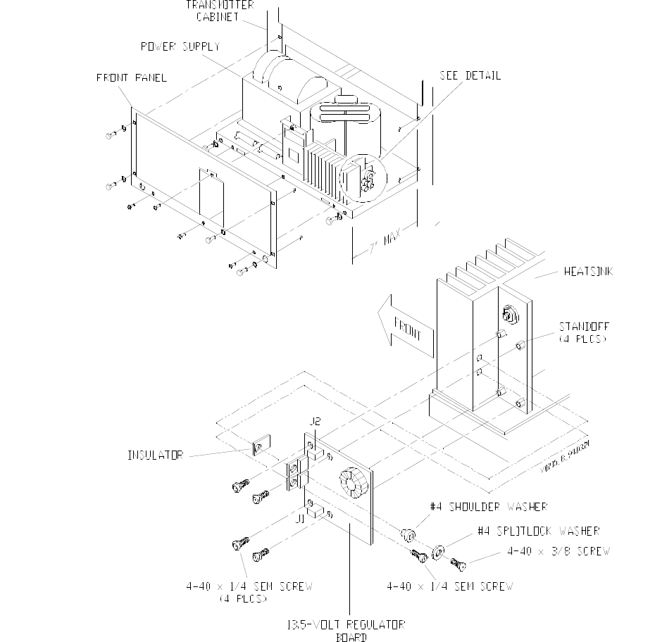
9.6 Removing and Reinstalling the 13.5-Volt Regulator
If it becomes necessary to replace the 13.5-volt regulator, perform the following proce-
dures. Refer to Figure 9-2, 13.5-Volt Regulator Board Removal and Reinstallation
throughout these procedures. It is assumed that the power supply chassis has been removed
from the rack.

Glenayre Document Number: 9110.00159 Gold Line Power Supplies
Issue 1, Rev. D: 02/01/96 REMOVAL AND REINSTALLATION
Print Date: 12/17/96 Copyright © 1996 Glenayre Page: 9-3
9.6.1 Removing 13.5-Volt Regulator
1. Carefully note electrical connections to board.
2. Remove connectors from J1 and J2.
3. Note arrangement of hardware on mounting screws and transistors. Replacing parts in
correct order is essential to successful assembly replacement.
4. Remove screws from heat-sink-mounted transistors.
5. Remove screws from On edges of pc assembly so that assembly comes loose from
standoffs..
6. Remove assembly
9.6.2 Reinstalling 13.5-Volt Regulator
1. Check insulators between transistors and heat sink for damage. Make sure that insula-
tors are undamaged and have adequate thermal compound on both sides and that no
grit or other foreign substances are embedded in thermal compound.
2. Place regulator assembly on standoffs by heat sink.
3. Replace screws which mount pc board to standoffs.
4. Replace screws and hardware to attach transistors to large heat sink.
5. Reattach electrical connections to J1 and J2.
Gold Line Power Supplies Glenayre Document Number: 9110.00159
REMOVAL AND REINSTALLATION Issue 1, Rev. D: 02/01/96
Page: 9-4 Copyright © 1996 Glenayre Print Date: 12/17/96
v0212.hgl
Figure 9-1 Power Supply Removal and Reinstallation from/into rack
Glenayre Document Number: 9110.00159 Gold Line Power Supplies
Issue 1, Rev. D: 02/01/96 REMOVAL AND REINSTALLATION
Print Date: 12/17/96 Copyright © 1996 Glenayre Page: 9-5
v0215.hgl
Figure 9-2 13.5-Volt Regulator Board Removal and Reinstallation
Gold Line Power Supplies Glenayre Document Number: 9110.00159
REMOVAL AND REINSTALLATION Issue 1, Rev. D: 02/01/96
Page: 9-6 Copyright © 1996 Glenayre Print Date: 12/17/96
Glenayre Document Number: 9110.00159 Gold Line Power Supplies
Issue 1, Rev. D: 02/01/96 OPTION
Print Date: 12/17/96 Copyright © 1996 Glenayre Page: 10-1
P
TION
Figure 10-1 Gold Line 50/90A DC Only Power Supply Assembly
Gold Line Power Supplies Glenayre Document Number: 9110.00159
OPTION Issue 1, Rev. D: 02/01/96
Page: 10-2 Copyright © 1996 Glenayre Print Date: 12/17/96
v0482.hgl
Figure 10-2 Gold Line 50A DC-Only Power Supply Functional Diagram
Glenayre Document Number: 9110.00159 Gold Line Power Supplies
Issue 1, Rev. D: 02/01/96 OPTION
Print Date: 12/17/96 Copyright © 1996 Glenayre Page: 10-3
v0483.hgl
Figure 10-3 Gold Line 90A DC-Only Power Supply Functional Diagram
Gold Line Power Supplies Glenayre Document Number: 9110.00159
OPTION Issue 1, Rev. D: 02/01/96
Page: 10-4 Copyright © 1996 Glenayre Print Date: 12/17/96
Glenayre Document Number: 9110.00159 Gold Line Power Supplies
Issue 1, Rev. D: 02/01/96 Index
Print Date: 12/17/96 Copyright © 1996 Glenayre Page: index-1
Index
Numerics
13.5-Volt Regulator Assembly 261-0082-001 10-3
A
ac line frequency 8-1
C
controls and indicators, front panel 5-2
D
description
13.5-volt regulator 6-1
detailed 6-1
simplified 3-2
diode check 8-1
G
Gold Line 50-A Power Supply Assembly 265-
0082-012 10-1
I
I/O connections 4-2
input voltage, setting power transformer jumpers 4-
3
M
manual contents 1-2
manual part numbers 1-1
R
rack units 3-1
removal and reinstallation
13.5-volt regulator 9-2
chassis 9-1
resonator capacitor 8-1
S
specifications 2-1
T
test equipment required 4-1
tools required 4-1
transformer check 8-1
Gold Line Power Supplies Glenayre Document Number: 9110.00159
TIssue 1, Rev. D: 02/01/96
Page: index-2 Copyright © 1996 Glenayre Print Date: 12/17/96