HUBSAN INTELLIGENT 501ARX HUBSAN X4 CAM BRUSHLESS WITH APP User Manual pt 2
SHENZHEN HUBSAN INTELLIGENT COMPANY LIMITED HUBSAN X4 CAM BRUSHLESS WITH APP pt 2
Contents
- 1. User Manual pt 1
- 2. User Manual pt 2
User Manual pt 2
16 ©2016 Hubsan
9. CALIBRATION
Push the left stick to the
most left side
Move the right stick left to right
quickly, the LCD
screen displays “Calib compass 1”
Rotate the X4 clock-wise
until the LCD screen displays
“Calib compass 2”
Put the X4 nose down and rotate
it counter clock-wise until
the ‘Calib compass 2” disappears
START
Calibration done
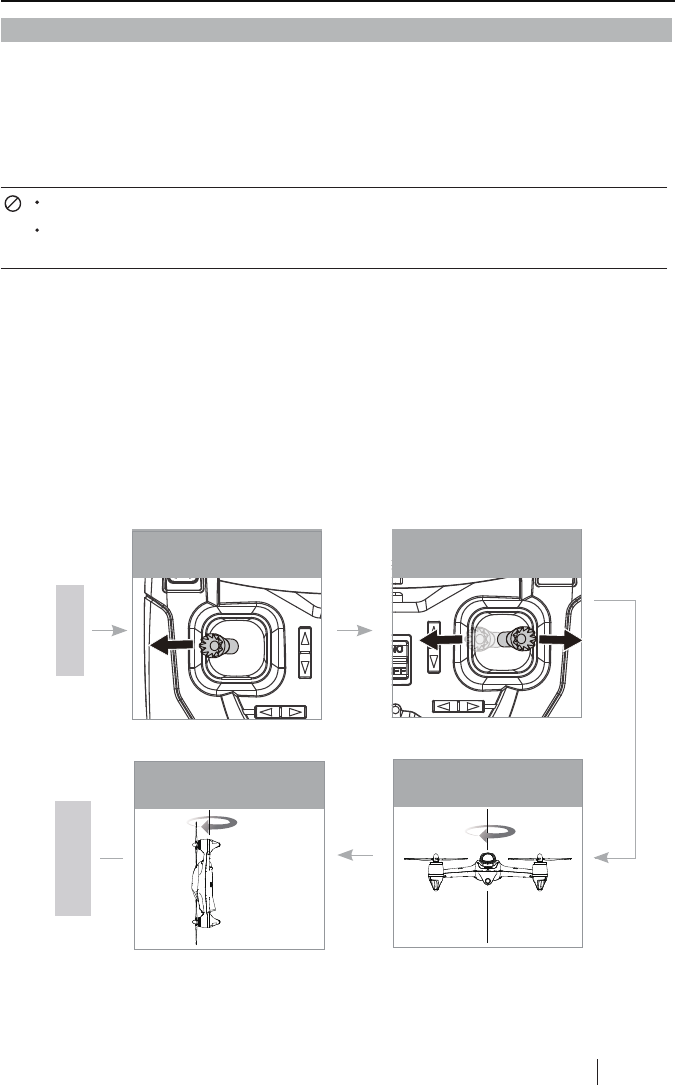
COMPASS CALIBRATION PROCEDURES
Please follow the calibrating procedures before the first flight.
1) Push the left stick to the most left side, and move the right stick left to right quickly until the
transmitter displays "Calib compass 1"
2) Rotate the X4 horizontally clock-wise until the LCD screen displays " Calib compass 2"
3) Put the X4 nose down and rotate it vertically clock-wise until the " Calib compass 2" on screen
disappears.
4) Calibration done.
Do not calibrate the compass in a strong magnetic field
Do not carry ferromagnetic materials with you while calibrating the compass,
such as keys, cell phones, etc.
9.1 COMPASS CALIBRATION
Compass calibration is required before the first time flight, otherwise the system may not work
properly. The compass is very sensitive to electromagnetic interference which can cause
abnormal compass data and lead to poor flight performance or even flight failure. Regular
calibration enables the compass is in optimum performance.
17 ©2016 Hubsan
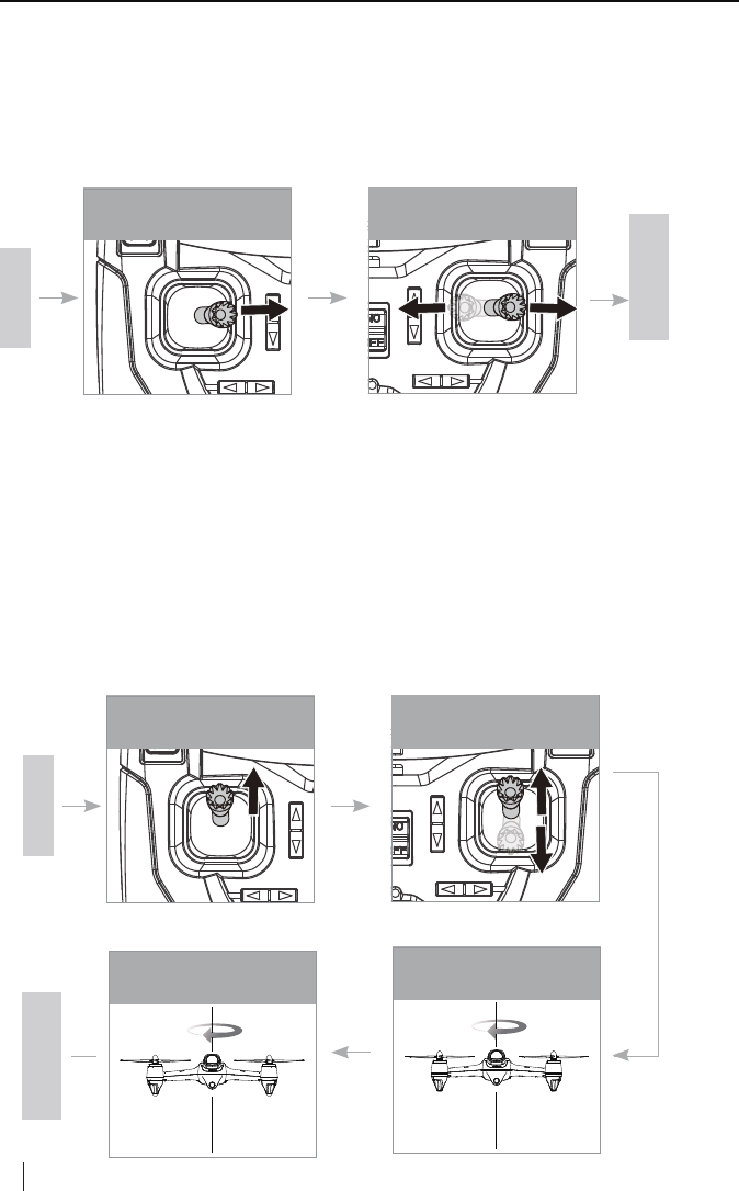
9.2 HORIZONTAL CALIBRATION
Horizontal calibration is required when the X4 is drift during flight.
Please follow the calibrating procedures:
1) Push the left stick to the most right side, and move the right stick left to right quickly until the 4
LED indicators blink in yellow slowly.
2) Calibration succeeded when the 4 LED indicators stop blinking slowly.
Push the left stick to the
most right side
Move the right stick left to right
quickly
START
Calibration done
9.3 ROTATION CALIBRATION
Rotation calibration is required when the X4 is yaw during flight.
Please follow the calibrating procedures and be sured that the X4 always on horizontal surface:
1) Push the left stick to the top side, and move the right stick up and down quickly until the 4 LED
indicators blink in yellow slowly
2) When the 4 LED indicators turns into red and blink circularly, rotate the X4 horizontally
clock-wise until the 4 LED indicators remain lighted in green
3) When the 4 LED indicators turns into red again, rotate the X4 horizontally clock-wise until the 4
LED indicators explosion-flashing simultaneously
4) Calibration done
Push the left stick to the top
side
Move the right stick up and down
quickly
Rotate the X4 clock-wise until LED
indicators remain lighted in green
START
Calibration done
Rotate the X4 clock-wise until
LED indicators explosion-flashing
simultaneously
18
2016 Hubsan
The transmitter will automatically find the best frequency to ensure a live video with good
quality of transmission. Please re-select the frequency from 5730MHZ to 5845MHZ to get a
better video transmission when necessary.
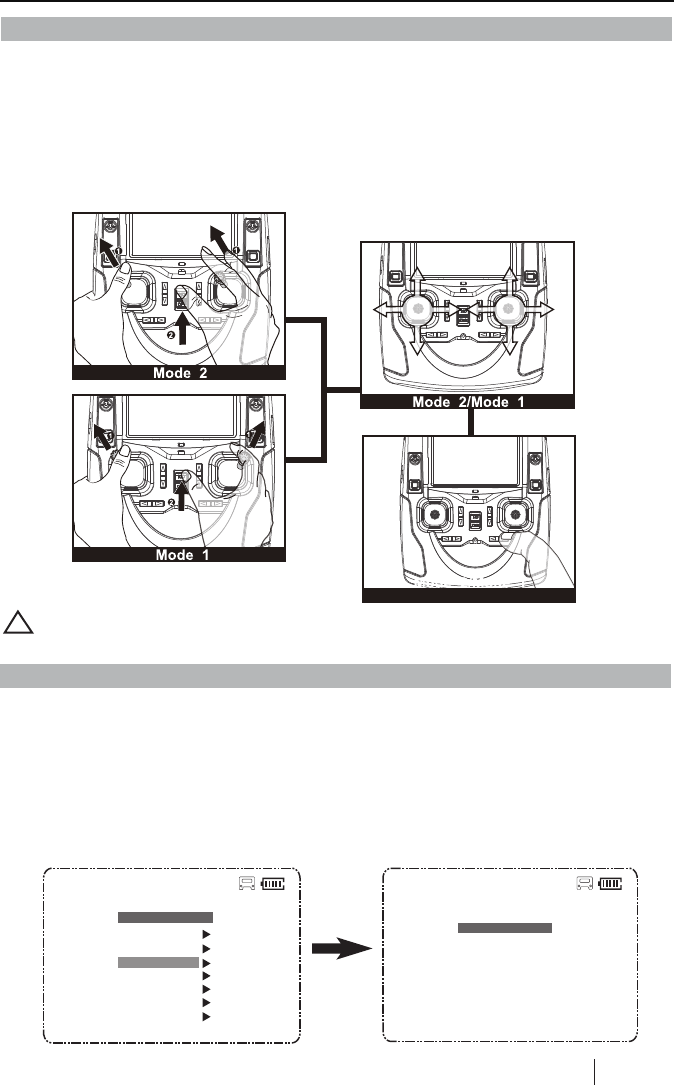
Pull the throttle stick to the lowest position and press the Elevator stick for 1.5 second to enter
into the MAIN MENU interface. Push the Elevator stick up/down to select “5.8G Frequency”,
push the stick to the right to enter into the “ 5.8G frequency” interface, select a matched
frequency.
5.8G FREQUENCY
0:08:49
Exit
5730MHZ
M2
Mode 2: Push both sticks to the upper left corner and power on the transmitter simultaneously, the
LCD will display “Calibrate Stick Mode 2”, rotate both sticks in circles for three times, release both
sticks, then press any trim for 1.5 seconds until one “beep” heard which indicates a successful
calibration.
Mode 1: Push the left stick to the upper left corner and the right stick to the upper right corner and
power on the transmitter simultaneously, the LCD will display “Calibrate Stick Mode 1”, rotate both
sticks in circles for three times, release both sticks, then press any trim for 1.5 seconds until one
“beep” heard which indicates a successful calibration.
The transmitter mode can be shifted according to the above operation.
!
0:08:49
MAIN MENU
Set Reverse
Set Sensitivity
5.8G Frequency
Set Manual
Fly When no GPS
Show Version
Exit
M2
10. TRANSMITTER STICK CALIBRATION
11. FREQUENCY SELECTABLE 5.8GHZ
12. X-HUBSAN APP
12.1 APP HOME PAGE
12.2 CAMERA
Download X-Hubsan APP in App Store or in Google Play.
In the camera interface,you can take and view all pictures/ videos you took with the HD
camera.
【1】Camera
: Click the icon to enter into camera interface.
【2】Album
: To view HD videos and pictures.
【3】Map
: Click the icon to enter into the map interface.
【4】Feedback
: For users to submit suggestions.
19 ©2016 Hubsan
【1】
Camera FeedbackAlbum Map
【2】 【3】 【4】
【1】
【14】
【10】
【11】
【12】
【13】
【2】 【3】 【4】 【5】【6】【7】 【8】
【9】
Connected Battery
capacity
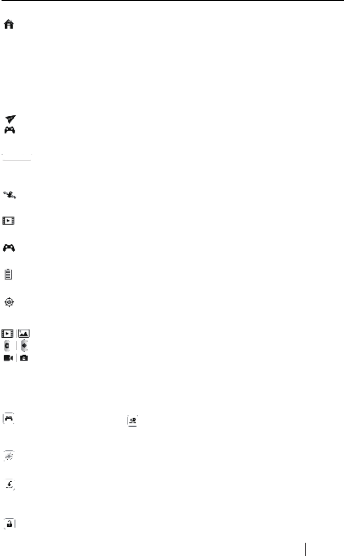
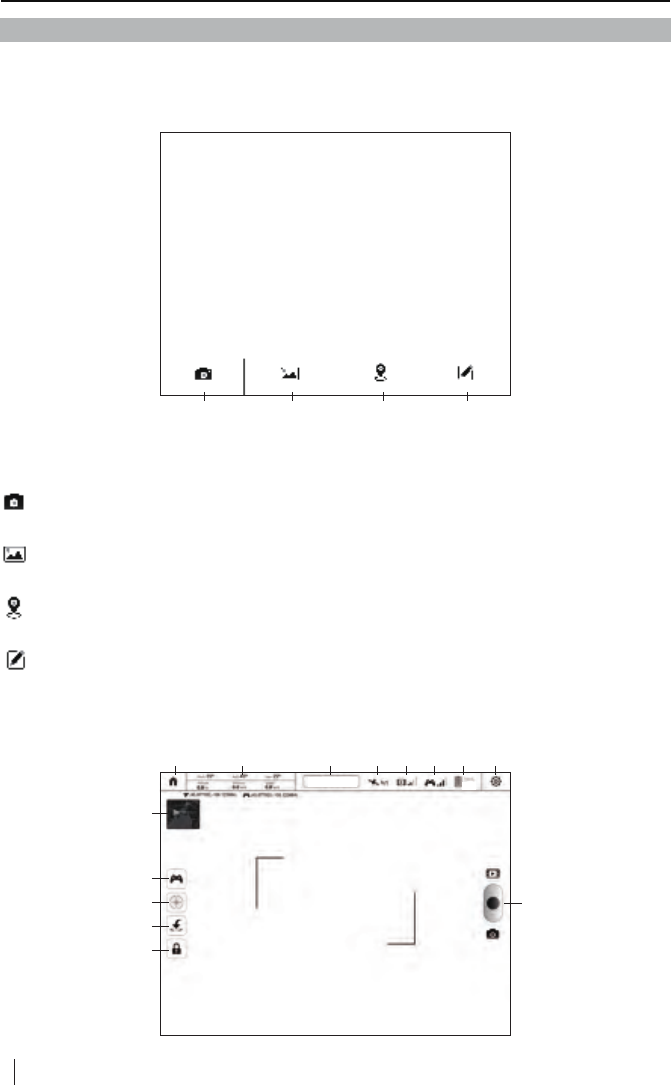
【1】HOME PAGE
: Click the icon to go back to home page.
: Display the longitude and latitude of the quadcopter.
: Display status of quadcopter and warnings. Quadcopter is connected when this
icon is in blue.
: Display the longitude and latitude of the control device.
: Display the current GPS signal.
Pitch: Pitch angle during flight.
Roll: Roll angle during flight.
Yaw: Yaw angle during filght.
Altitude: Vertical height from the ground.
Distance: Horizontal distance between quadcopter and control device.
Speed: Current flight speed.
【2】FLIGHT DATA
【3】X4 STATUS BAR
【4】GPS SINGAL
: Display the signal of FPV transmission.
【5】VIDEO SIGNAL
: Display the connection signal between quadcopter and control device.
【6】TRANSMITTER SIGNAL
: Display the quadcopter battery level. For safety, please land the quadcopter when the battery is low.
【7】POWER
: Click the icon to adjust flight settings according to personal preferences.
: Tap the icon to view pictures and videos.
: Tap the icon to take pictures and videos.
: Tap the icon to shift between picture mode and video mode.
【8】SETTINGS
: Click the icon to enter/exit headless mode.
【11】HEADLESS MODE
Default setup is stick mode, tap the screen, the sticks will show on the screen and use the
sticks to control quadcopter.
: Click the icon, it will shift to , and enter into waypoint mode. The tansmitter mode
is not available.
【10】TRANSMITTER MODE
【9】CAMERA
: Click the icon to turn on/off RTH mode.When RTH mode is activated, the quadcopter
will fly back to the takeoff point automatically.
【12】RETURN TO HOME
: Click the icon and slide the screen as instructed to arm the motors.
【13】ARM/DISARM MOTORS
After quadcopter took off, click the icon again and slide the screen as instructed to
disarm the motors and land the quadcopter. 20 ©2016 Hubsan
Connected
21 ©2016 Hubsan
: Tap the thumbnail window to enter into map interface.
【14】Map Thumbnail Window
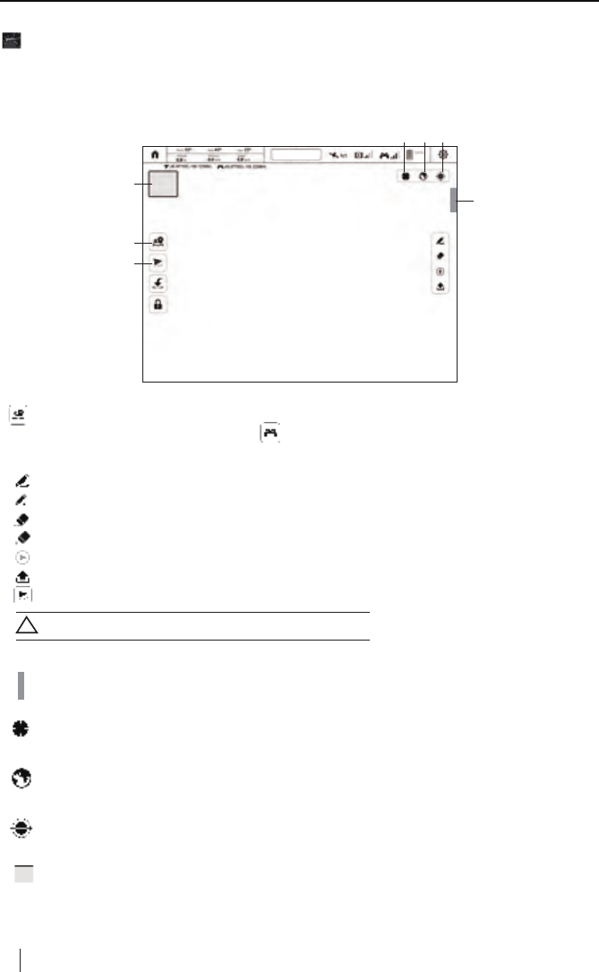
12.3 WAYPOINT MODE
【1】Waypoint Mode
: Click the icon to set up user location as the center point of map.
Waypoint mode can be activated/deactivated in the map interface, which allows user to define
waypoints and make the quoadcopter to fly according to the user defined waypoints.
: Click the icon, the quadcopter will fly according to waypoints.
Click the icon again, it will shift to , and exit waypoint mode.
【3】History
: Click the icon to check flight record.
【2】Waypoint Setup
: Tap the icon to set the flight path.
: Tap the icon to set waypoint, and the flight path will be composed of waypoints in sequence.
: Tap the icon to delete all waypoint data.
: Tap the icon and then click one waypoint, you can detele it.
: Tap the icon to set the nose direction.
: Tap the icon to submit waypoint data to quadcopter.
【4】Map Center
: Click the icon to set up user location as the center point of map.
: Tap the icon, then long press the map to make calibration automatically.
【5】Map Mode
Normal Mode; Satellite Mode; Mixed Mode.
【6】Map Calibration
: Tap the thumbnail window to enter into camera interface.
【7】Camera Thumbnail Window
Make sure to submit waypoints data after finished.
!
History
Connected Battery
capacity
History
【1】
【7】
【2】
【3】
【4】
【5】【6】
22 ©2016 Hubsan
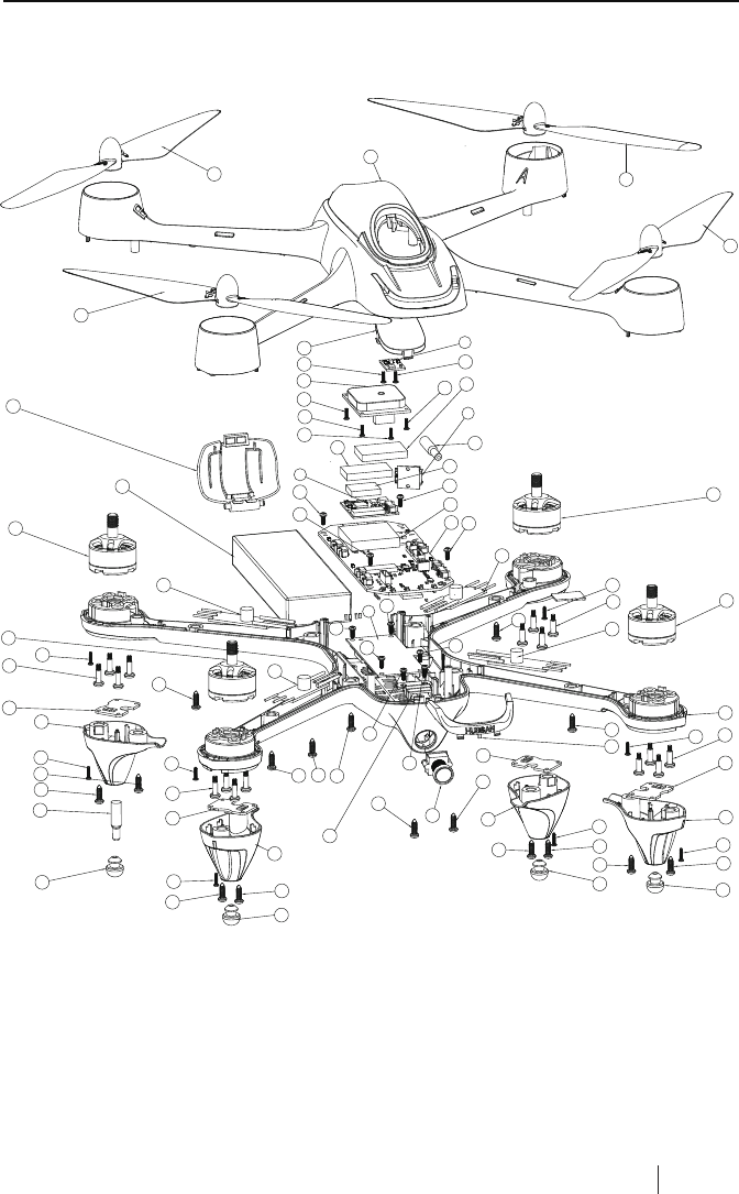
EXPLODED VIEW
6
9
10
15
17
9
9
9
10
15
15
15
8
11
16
1
19
20
21
24
27
11
27
27
27
34
32
32
32
32
32
32
32
32
32
32
32
32
32
32 32
12
7
35
35
35
35
34
33
33
34
4
25
25
26
26
5
18
31 31
31
31
2
31
31
31 31
31
31
32
30
31
30
31
22
22 23
23
34
13
14
28
29
3
33
33
33
33

23 ©2016 Hubsan
01
02
03
04
05
06
07
08
09
10
11
12
13
14
15
16
17
18
NO. PART NAME QTY
19
20
21
22
23
24
25
26
27
28
29
30
31
32
33
34
35
NO. PART NAME QTY
Lower Body Shell
Main Control Board
Power Board
5.8 GHz Transmission PCBA
Compass PCBA
GPS Module
USB PCBA
Camera Module
ESC
Motor A
Motor B
Li-Po Battery
2.4G Attenna
5.8G Attenna
LED PCBA
Upper Body Shell
2.4GHz Shielding Case
Sponge
Battery Cover
Canopy
Eye Lampshade
Motor A Lampshade
Motor B Lampshade
Lens Holder
Propeller A
Propeller B
Rubber Feet
Shielding Case
Sponge
Screw
Screw
Screw
Screw
Screw
Screw
1
1
1
2
2
1
2
2
4
1
1
4
10
16
8
2
16
1
1
1
1
1
1
1
1
4
2
2
1
1
1
4
1
1
1
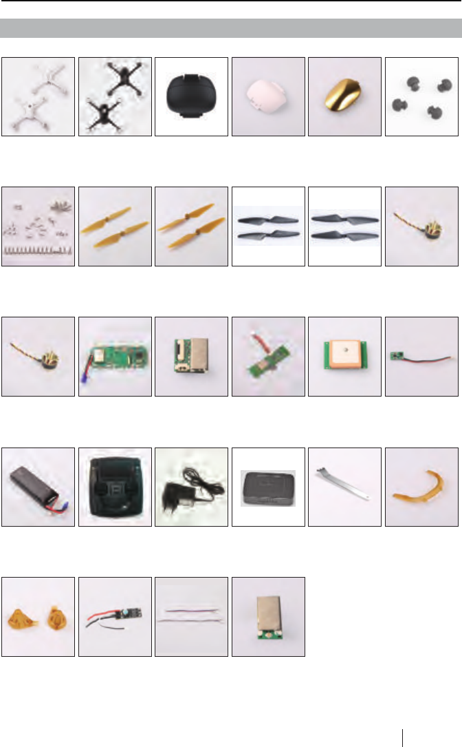
H501S SPARE PART CHART
H501S-01
Body Shell
Set- White
H501S-22
Body Shell
Set- Black
H501S-02B
Battery
Cover- Black
H501S-02
Battery
Cover- White
H501S-03
Canopy
H109-04
Rubber Feet
H501S-04
Screw Set
H501S-05
Propeller
A- Gold
Propeller
B- Gold
H501S-06 H501S-05B
Propeller
A- Black
H501S-06B
Propeller
B- Black
H501S-07
Brushless
Motor A
H501S-08 H501S-09
PCB Module
H501S-10
Flight Control
PCB Module
H501S-11
5.8G Transmission
Module
H501S-13
Compass Module
H501S-14
Lipo Battery
2700MAh
H501S-15
Remote
H301S-11
Adapter
H501S-17
Eye Lampshade
Brushless
Motor B
H501S-12
GPS Module
H501S-16
U Wrench
H301S-12
Balance Charger
H501S-18
Motor LED
Lampshade
H501S-19
ESC
H501S-20
LED PCBA
H501S-21
2.4G Receiver
Module
24 ©2016 Hubsan
FCC INFORMATION
This equipment has been tested and found to comply with the limits for a Class B digital device,
pursuant to Part 15 of the FCC Rules. These limits are designed to provide reasonable protection
against harmful interference in a residential installation. This equipment generates, uses, and can
radiate radio frequency energy and, if not installed and used in accordance with the instructions, may
cause harmful interference to radio communications. However, there is no guarantee that interference
will not occur in a particular installation. If this equipment does cause harmful interference to radio or
television reception, which can be determined by turning the equipment off and on, the user is
encouraged to try to correct the interference by one or more of the following measures:
• Reorient or relocate the receiving antenna.
• Increase the separation between the equipment and receiver.
• Connect the equipment into an outlet on a circuit different from that to which the receiver is
connected.
• Consult the local dealer or an experienced radio/TV technician for help.
Changes or modifications not expressly approved by the party responsible for compliance could void
the user’s authority to operate the equipment.
This device complies with Part 15 of the FCC Rules. Operation is subject to the following two
conditions: (1) this device may not cause harmful interference, and (2) this device must accept any
interference received, including interference that may cause undesired operation.
ENVIRONMENTALLY FRIENDLY DISPOSAL
Old electrical appliances must not be disposed of together with the residual waste, but have to be disposed of
separately. The disposal at the communal collecting point via private persons is for free.
The owner of old appliances is responsible to bring the appliances to thise collecting
points or to similar collection points. With this little personal effort, you contribute to recycle
valuable raw materials and the treatment of toxic substances.
25 ©2016 Hubsan

User manual is subject to change without prior notice due to
unforseen product upgrades.
Download the latest user manual from
WWW.HUBSAN.COM
VERSION 1.0 EN