HARRIS M7200 M7200 700/800 MHz Mobile Radio User Manual manual 1
Harris Corporation M7200 700/800 MHz Mobile Radio manual 1
UserManual.wiki
>
HARRIS
>
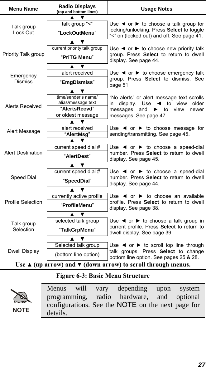
M7200 User Manual
>
manual 1
Contents
1.
manual 1
2.
manual 2
3.
Manual 1
4.
Manual 2
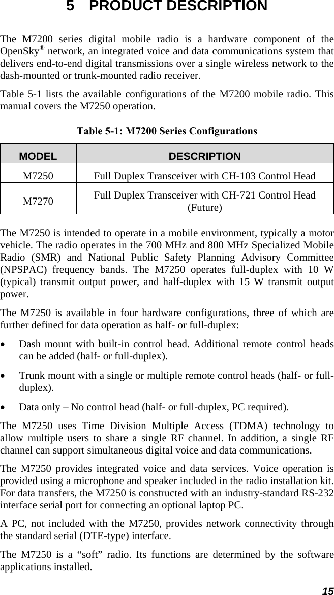
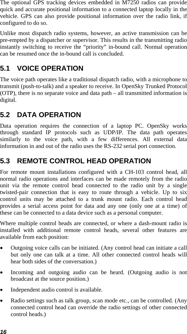
5.
Manual
6.
User Manual
manual 1
Navigation menu
Upload a User Manual
Namespaces
Wiki Guide
HTML
PDF
Info
Views
User Manual
Discussion / Help
Navigation

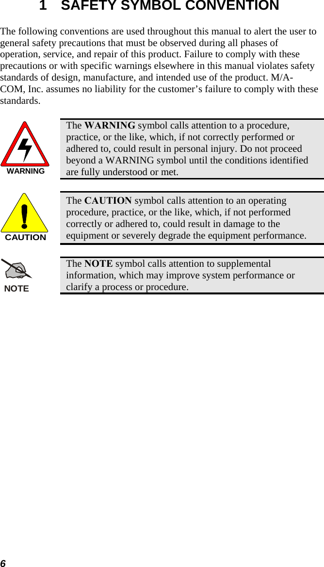
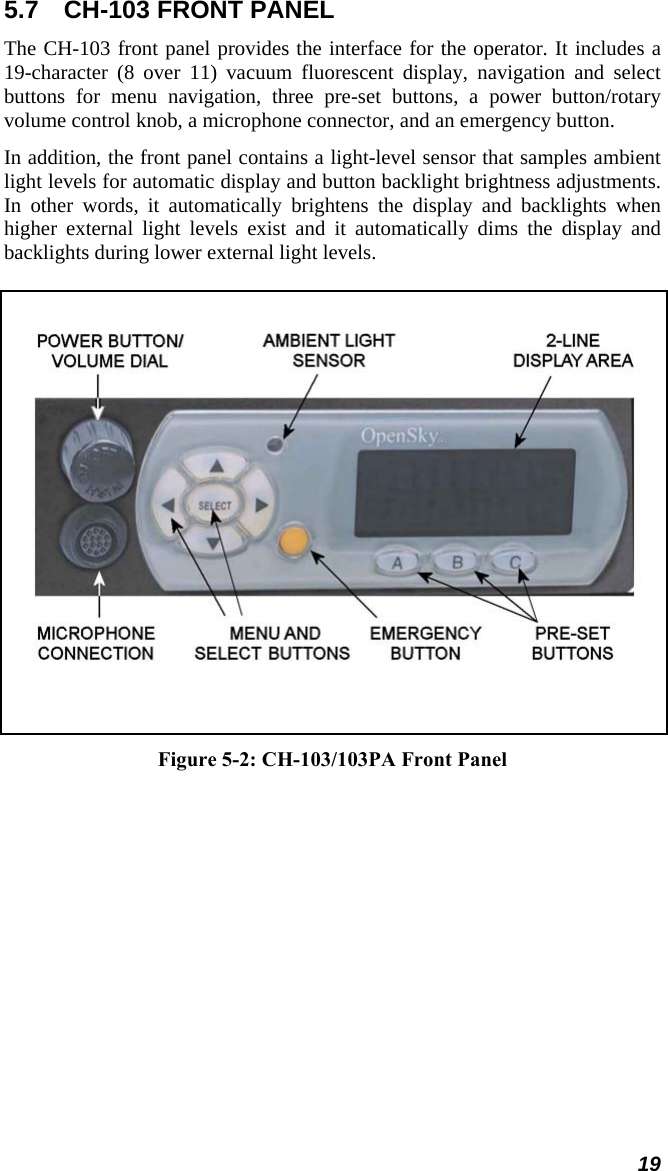
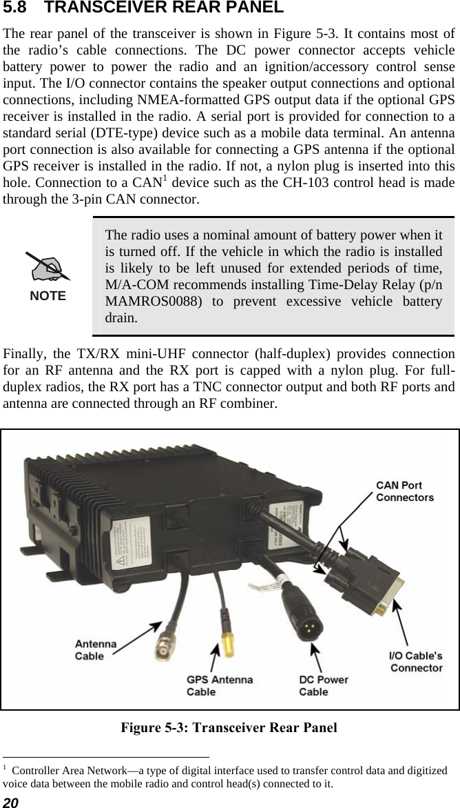
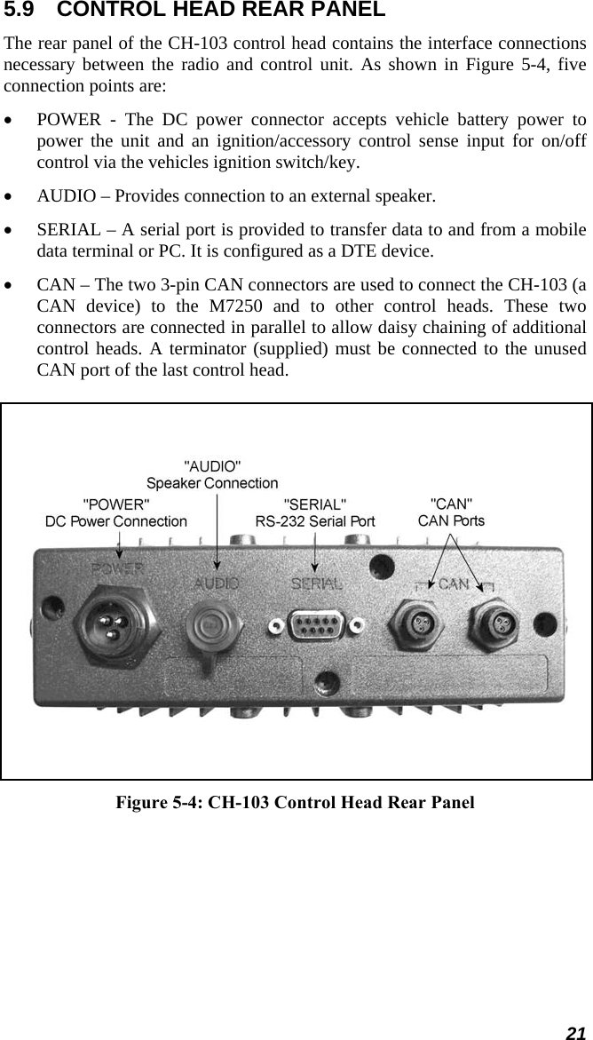
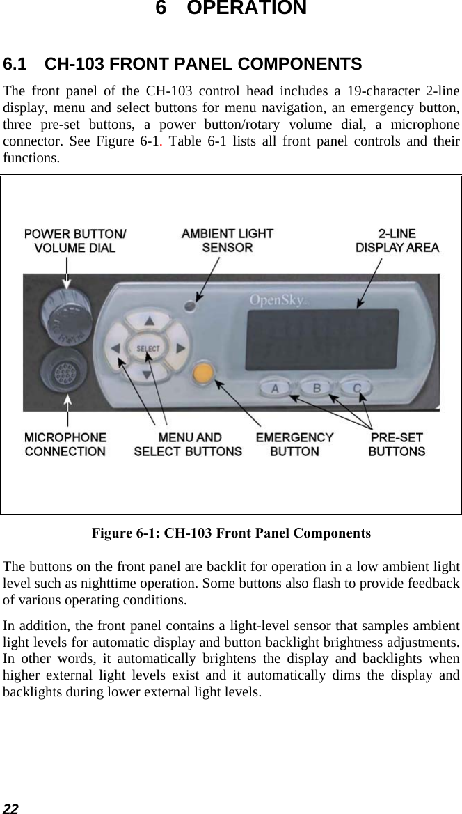
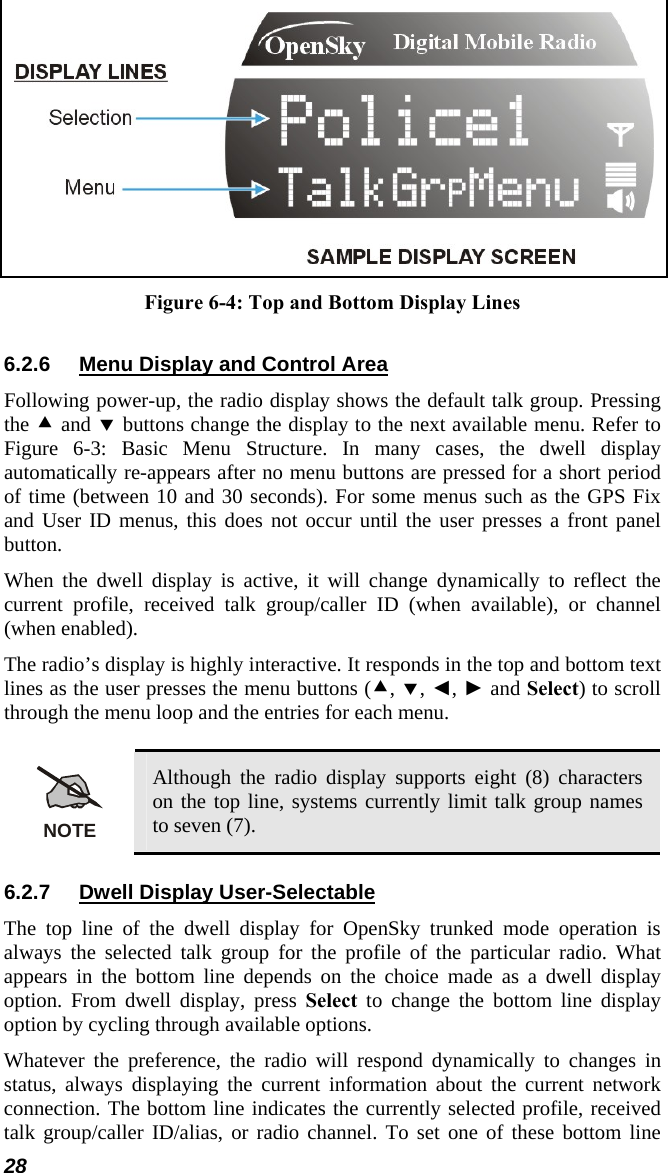
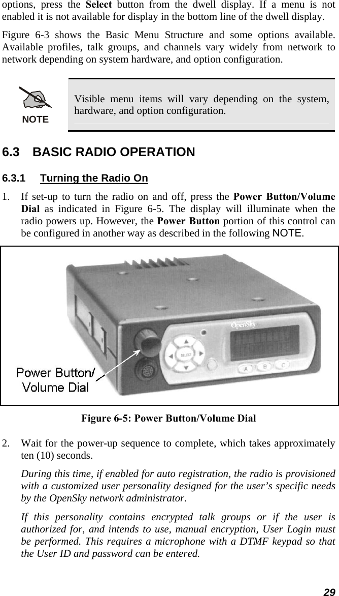
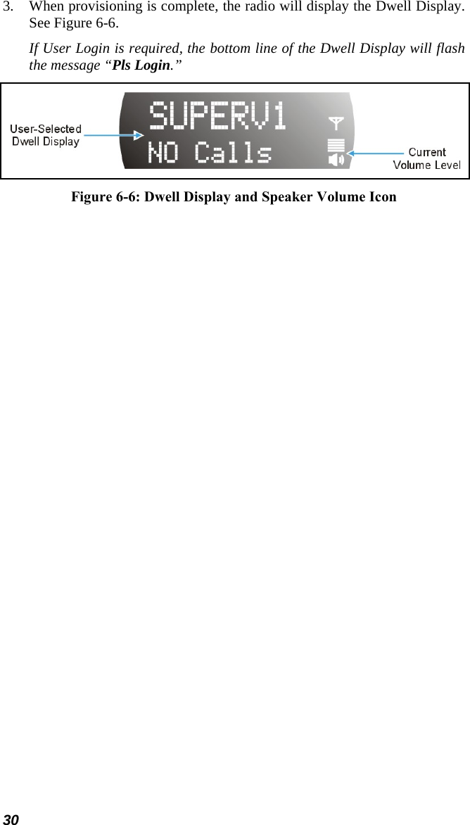
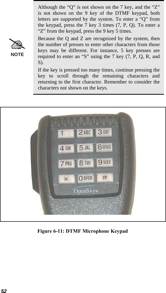
![To perform a command from the keypad, press the * key followed by one of the pre-set function keys as follows: *0 Log-off command: *0## (logs the user off the system). See page 33 for additional information. *1 Log-in command: *1<User ID> # <Password> ## (required for encryption). See page 32 for additional information. *5 Single Site Channel command: *5<SMR/NPSPAC channel># *6 Load Default Personality command: *6#. This command applies only if the radio is not voice-registered on the network. *7 Initiate Selective Alert command: *7<Target ID>#[Choose Message]#. See page 46 for additional information. *8 Radio-to-Radio Call command: Selective call number # (PTT to dial). See page 44 for additional information. *9 Public Switched Telephone Network (PSTN) Call command: See page 48 for additional information. *32 Begin Manual Encryption command: *32<Pre-Determined Encryption Key of Up To 16 Digits># See page 54 for additional information. *33 End Manual Encryption command: *33#. NOTE When entering letters or numbers from the keypad that has if two or more adjacent characters represented by the same key on the keypad, the pound (#) key must be pressed after all but the last of the adjacent characters. For example, to enter MACOM6, press the following keys: 6 key twice (M), 2 key twice (A), # key, 2 key 4 times (C), 6 key 4 times (O), # key, the 6 key twice (M), # key, and then the 6 key once (6). Press the # key twice to complete the entry. 6.10.1 Password Entry Password entry requires a DTMF microphone. Password characters are encrypted on the display using symbols to indicate the entry. The encryption symbols for each entry will appear in the display as they are scrolled through, for example: '-' and '+'. Press the # key twice to complete the entry process. Refer to the above NOTE for more details. If the radio is configured for alpha-numeric passwords and the password has consecutive duplicate numbers (“MES33” for example), enter # between the consecutive duplicate numbers so the radio will not interpret the entry as a letter (“D” in this example). If the radio is configured for numeric-only passwords, do not enter # between duplicated numbers. 53](https://usermanual.wiki/HARRIS/M7200.manual-1/User-Guide-588516-Page-53.png)