Contents
Users Manual 1

User's Manual
UM4710Ver. A2
Hi-G-Tek Ltd. Microelectronics and Asset Tracking Technology
DataReader
and
DataSeal
System
Table of Contents Page
1. Introduction
2. DataSeal Installation
1.1. About the Product
1.2. DataReader System Components
1.2.1. DataSeal Mounting Fixture
1.2.2. The DataSeal
1.2.3. Seal Wire
1.2.4. Outdoor DataReader
1.2.5. Indoor DataReader
Hi-G-Tek Ltd. Microelectronics & Asset Tracking Technology 2
16
19
19
19
20
15
3. DataReader Installation
3.1 Outdoor DataReader Installation
3.1.1 Connecting the Outdoor Unit
3.1.2 Ceiling Installation
3.1.3 Wiring the Outdoor Datareader
3.1.4 DataReader Configuration switches
3.1.5 RS232 Wiring Diagram
3.1.5 RS-485 Full Duplex Wiring Diagram
3.1.6 RS-485 Half Duplex Wiring Diagram
3.2 Indoor DataReader Installation
3.2.1 Connecting the Indoor Unit
3.2.2 Ceiling Installation
3.2.3 Wiring the Indoor DataReader
3.2.4 RS-232 Wiring Diagram
3.2.5 RS-485 Full Duplex Wiring Diagram
3.2.6 RS-485 Half Duplex Wiring Diagram
3.3 Chaining DataReaders Together
3.4 RS-232/RS-485 Adapter
2.1. DataSeal Installation
20
22
25
26
29
30
30
31
32
33
33
34
34
36
37
38
39
39
40
43
41
43
44
3.4.1 Connecting the RS-232/RS-485
Adapter to the First Reader
3.4.2. Connecting the RS-232/RS-485
Adapter to the Host
5.1. System Description
Table of Contents Page
Hi-G-Tek Ltd. Microelectronics & Asset Tracking Technology 3
5. The System
49
46
45
50
50
57
57
63
66
66
67
68
68
69
70
70
70
71
71
72
72
72
73
73
73
5.3. Parameters Format
5.2.1. Seal's Parameters
5.2.2. Reader's Parameters
5.2.3. Calculating Thw
5.2.4. Calculating Tw
5.2.5. Calculating Thp
5.4.1. Normal Mode
5.4.2. Sleep Mode
5.4.3. Alert Burst Mode
5.4.4. Events Footprint Mode
5.4 Seal Modes of Operations
5.5. Reader Modes of Operation
5.5.1. Carrier Sense Collision
5.5.2. Unsynchronized Mode
5.2. System Parameters
5.1.1. General
5.3.1. Date & Time
5.3.2.
5.3.3. ORG_ID & Department
5.3.4. System
5.3.5. Mode
Seal Serial Number.
74
74
76
76
5.6. System Commands
5.6.1. LSC and Reader Messages
5.6.2. Error Codes
5.6.3. Detailed Commands
3.5. Power Supply Requirements
3.6. Communication Cable Selection
3.7. Installation notes
47
4. DataReader Operation Instructions
44
Hi-G-Tek Ltd. Microelectronics & Asset Tracking Technology 4
Table of Contents Page
77
5.6.3.2. Execute RF Command
85
86
89
91
5.6.3.3. Get Results
5.6.3.4. Get Status
77
77
79
79
80
80
81
81
81
82
83
83
83
84
85
84
85
84
82
5.6.3.2.1. Command
Transmission
5.6.3.2.2. Verify
5.6.3.2.3. Tamper
5.6.3.2.4. Set
5.6.3.2.5. Suspended Set
5.6.3.2.6. Soft Set
5.6.3.2.7. Deep Sleep
5.6.3.2.8. Hard Wakeup
5.6.3.2.9. Start Alert
Burst Mode
5.6.3.2.10. Stop Alert
Burst Mode
5.6.3.2.11. Ack Alert
Burst Mode
5.6.3.2.12. Read Data
5.6.3.2.13. Write Data
5.6.3.2.14. Reset Data
5.6.3.2.15. Set/Reset Status
5.6.3.2.16. Write Parameters
5.6.3.2.17. Read Parameters
5.6.3.2.18. Addressed Verify
5.6.3.2.19. Read Events
5.6.3.5. Get Burst Message
5.6.3.6. Reset Reader
5.6.3.7. Write Parameters 92
76
76
5.6.3.1. Wakeup
5.6.3.1.1. Command
Transmission
Hi-G-Tek Ltd. Microelectronics & Asset Tracking Technology 5
Table of Contents Page
5.6.3.8. Read Parameters
5.6.3.9. BIT
93
94
95
95
96
96
5.6.3.10. Sleep
5.6.3.11. Unsynchronized Reader
Message
5.6.3.12. Get Reader's Baud Rate
5.6.3.13. Set Reader's Baud Rate
97
98
98
98
5.6.3.14. Set Reader's Address
5.6.3.15. Acknowledge OK
5.6.3.16. Acknowledge Failed
5.6.3.17. Save Command
100
101
5.6.3.18. Execute Saved
Command
5.6.3.19. Reader Channels
Definitions Command
103
103
104
104
105
106
106
5.7. System Planning
5.7.1. Electromagnetic Environment
5.7.2. System Layout
5.7.2.1. Radio Frequency
Communication Layout
5.7.2.2. Cellular Layout
5.7.2.3. Reader Sessions
Retransmissions
5.7.2.4. Line Communications
RS-485 Layout
Hi-G-Tek Ltd. Microelectronics & Asset Tracking Technology 6
Table of Contents Page
107
5.8. System Segregation
107
107
108
108
109
5.8.1. Company Segregation by ORG_ID
5.8.2. Department Isolation
5.8.3. Common Services to Several
Companies by a Service Provider
5.8.4. How to use subgroups of Seals in
a Company
5.8.5. ORG_ID, Global and ADI: Impact on
Seal's Response
109
112
5.9. Seal Memory
5.10. Calculating Reader Session Duration
109
113
113
111
5.9.1. Events Memory
5.9.2. User Data
6. RS-485/232 Communication Protocol
6.1. RS-485/232 Communication Protocol:
General Description
6.2. Physical Layer
6.2.1. Down Link
6.2.2. Up-Link
115
116
116
116
116
6.4.1. LSC to READERS Messages
6.3. Protocol Flow
6.4. String Format
6.4.1.2. CMND Field Structure
6.4.1.1. CRC Calculation
116
119
119
120
119
5.10.1. Calculating Tbmm
5.10.2. Calculating Trw
Hi-G-Tek Ltd. Microelectronics & Asset Tracking Technology 7
Table of Contents Page
6.5.1. LSC Commands and Acknowledge
Table
6.5.2. Message Table
6.5.3. Parameter Table
6.5. LSC and READER Messages
6.5.3.1. Reader Master Firmware
Vresion MVER
6.5.3.2. Reader Slave1 Firmware
Version SVER1.
6.5.3.3. Reader Slave1 Firmware
Version SVER2
127
127
128
129
130
130
130
6.4.2. READER to LSC Messages
6.4.2.2. R_Status Field Structure
6.4.2.3. Reader Messages Packed
Data Format
6.4.2.3.1. Packed Data from
the LSC
6.4.2.3.2. Packed Data from
the READER
123
126
121
126
126
6.5.3.5. Reader ID RID
6.5.3.6. Group Access Identifier ADI
Organization identifier OrgID6.5.3.7.
6.5.3.8. Department DEP
6.5.3.9. Reader IH length Thw
6.5.3.10. Reader Address RADD
6.5.3.11. Mode MODE
Reader Receives Signal 6.5.3.4.
Strength RSSI1 131
131
132
133
133
133
132
132
Hi-G-Tek Ltd. Microelectronics & Asset Tracking Technology 8
Table of Contents Page
6.5.5.1. Wakeup
6.5.5.2. Execute RF Command
6.5.5.2.1. Command
Transmission
6.5.5.2.2. Execute RF
Command Ack
6.5.5.2.3. Verify
6.5.5.2.4. Tamper
6.5.5.2.5. Set
6.5.5.2.6. Suspended Set
6.5.5.2.7. Soft Set
6.5.5.2.8. Deep Sleep
6.5.5.2.9. Hard Wakeup
6.5.5.2.10.Start Alert Burst Mode
6.5.5.2.11. Stop Alert Burst Mode
6.5.5.2.12. Acknowledge Alert
Burst Mode
6.5.5.2.13. Read Data
6.5.5.2.14. Write Data
6.5.5.2.15. Reset Data
6.5.4. Error Codes
6.5.5. Detailed Commands
6.5.5.1.1. Command
Transmission
6.5.5.1.2 Wakeup Response
135
135
135
135
136
138
139
140
140
140
141
141
141
142
142
137
138
139
135
135
134
6.5.5.2.17. Write Parameters
6.5.5.2.18. Read Parameters
6.5.5.2.19. Addressed Verify
6.5.5.2.20. Read Events
142
143
143
143
143
6.5.5.2.16 Set/Reset Status

Hi-G-Tek Ltd. Microelectronics & Asset Tracking Technology 9
Table of Contents Page
6.5.5.3.1. Command
Transmission
6.5.5.3.2. Get Results Command
General Response
6.5.5.3.3. Get Results Command
Response for Verify
Command
6.5.5.3.4. Get Results Command
Response for Tamper
Command
6.5.5.3.5. Get Results Command
Response for Set
Command
6.5.5.3.6. Get Results Command
Response for Suspended
Set Command
6.5.5.3.7. Get Results Command
Response for Soft Set
Command
6.5.5.3.8. Get Results Command
Response for Read Data
Command
6.5.5.3.9. Get Results Command
Response for Write Data
Command
6.5.5.3.10.Get Results Command
Response for Deep Sleep
Command
6.5.5.3. Get Results 144
144
144
146
147
147
147
147
147
148
148
6.5.5.3.11. Get Results Command
Response for Hard
Wakeup Command 148
Hi-G-Tek Ltd. Microelectronics & Asset Tracking Technology 10
6.5.5.3.12. Get Results Command
Response for Reset
Data Command
6.5.5.3.13. Get Results Command
Response for Start Alert
Burst Mode Command
6.5.5.3.14. Get Results Command
Response for Stop Alert
Burst Mode Command
6.5.5.3.15. Get Results Command
Response for Start Alert
Burst Mode Command
6.5.5.3.16. Get Results Command
Response for Write
Parameters Command
6.5.5.3.17. Get Results Command
Response for Read
Parameters Command
6.5.5.3.18. Get Results Command
Response for Addressed
Verify Command
6.5.5.3.19. Get Results Command
Response for Read
Events Command
Table of Contents Page
6.5.5.4. Get Status
6.5.5.5. Get Burst Message
149
149
149
150
150
150
151
151
153
153
6.5.5.6. Reset Reader 155
6.5.5.8. Read Parameters 157
6.5.5.7. Write Parameters 156
6.5.5.9. BIT
6.5.5.10. Sleep
158
158
Hi-G-Tek Ltd. Microelectronics & Asset Tracking Technology 11
Table of Contents Page
6.5.5.11. Unsynchronized Reader
Message.
6.5.5.12. Get Reader's Baud Rate
159
160
6.5.5.13. Set Reader's Baud Rate
6.5.5.14. Set Reader's Address
6.5.5.15. Acknowledge OK
6.5.5.16. Acknowledge Failed
6.5.5.17. Save Command
6.5.5.18. Execute Saved Command
6.5.5.19. Read Channel Definitions
Command
6.5.5.20. Write Channel Definitions
Command
160
162
162
163
164
165
162
161
167
7. Evaluation Software
168
168
168
169
7.1. Software Installation
7.2. Communication Setup-
Readers Administration
7.2.1 Defining the Readers
Connected
7.2.2 Setting up the
Communication Channel
170
170
170
7.3. Readers Setup
7.3.1 MCU Setup
7.3.2 RF Modem Setup
171
172
7.4. Built-In Test
7.5. Login-Password Setup.
Password Change
Hi-G-Tek Ltd. Microelectronics & Asset Tracking Technology 12
Table of Contents Page
176
176
176
7.7.1 Selecting the Reader.
7.7.2 Broadcast Sessions.
7.7. Performing Verify and Set cycles
177
179
179
180
179
181
7.7.2.1 Setting Session's
Parameters.
7.7.2.2 ADI Definition.
7.7.2.3 Reader Session
7.7.2.4. Single Session
7.7.2.5 Multiple Sessions
7.7.2.6 Reading the Results
174
175
174
7.6.1 MCU Software Update
7.6.2 RF Modem Software
Update
7.6. Download DataReader
Software Utility
182
182
183
7.7.3 Addressed Verify
Sessions
7.7.3.1 Single Session
7.7.3.2 Multiple
Sessions
7.7.4 SET Sessions
7.7.3.3 Reading the
Results 185
186
Hi-G-Tek Ltd. Microelectronics & Asset Tracking Technology 13
Table of Contents Page
7.8. Performing General Commands Cycles.
7.8.1 Selecting a Reader.
7.8.2 Selecting a Command
7.8.3 Defining Seals
7.8.4 Setting the System Session Duration
7.8.5 Setting the Command Parameters.
7.8.6 Single or Continuous Sessions.
7.8.7 Commands.
187
188
188
189
190
191
189
187
7.8.7.1 Verify Command
7.8.7.2 Tamper Command
7.8.7.3 Addressed Verify
7.8.7.4 Set
7.8.7.5 Soft Set
7.8.7.6 Suspended Set
7.8.7.7 Read Data
7.8.7.8 Write Data
7.8.7.9 Read Parameter
7.8.7.10 Write Parameter
7.8.7.11 Reset Data
7.8.7.12 Deep Sleep
7.8.7.13 Hard Wakeup
7.8.7.14 Start Alert Burst
7.8.7.15 Start Alert Burst (all)
193
193
194
191
196
197
198
199
200
200
201
201
202
203
7.8.7.16 Stop Alert Burst
7.8.7.17 Stop Alert Burst (all)
7.8.7.18 Ack Alert
7.8.7.19. Read Events
204
205
204
206
195
Hi-G-Tek Ltd. Microelectronics & Asset Tracking Technology 14
207
208
208
211
212
213
213
214
215
215
216
217
219
9.1. 24v Outdoor DataReader
9.2. 12v Outdoor DataReader
9.3. 48v Outdoor DataReader
9.4. 24v Indoor DataReader
9.5. 12v Indoor DataReader
9.6. 48v Indoor DataReader
9.7. DataSeal
9.8. Magnetic DataSeal
8.1. DataReader Troubleshooting
8.2. Evaluation System Troubleshooting
9. Technical Specifications
8. Troubleshooting
Table of Contents Page
10. Index

Introduction
Chapter 1

Introduction
1
Hi-G-Tek Ltd. Microelectronics & Asset Tracking Technology 16
The Hi-G-Tek range of products provides a highly reliable and secure
cargo and asset monitoring system utilising state-of-the-art RFID
technologies.
1.1. About the Product
The Hi-G-Tek system was developed in order to fill the requirement
for fast, automatic processing of secured cargoes and to provide real
time monitoring and improved management of cargoes both in
transit and in storage.
The DataSeal is a sophisticated device, which includes a
transmitter/ receiver unit, real-time clock, processor, memory
and sensing circuitry for sealing verification. The Sealing Wire
prevents any attempt of opening, bypassing or tampering with the
seal without alerting the system and recording of the event. The
system combines the technological and operational advantages of
both low frequency close-range data management AND high
frequency long range sealing verification and automatic data
collection.
DataSeal's ability to log data and communicate it through a
Handheld DataTerminal is best used In low frequency/short range
applications. This way the electronic manifest of the sealed cargo
can be written into the DataSeal's memory. The information includes
Vehicle ID, container and invoice numbers, cargo description,
quantities, destination, etc. Capable of logging up to 55 events, the
information can be downloaded into a computerised database for
storage and processing.
Cost-effective, more reliable and more secure than their mechanical
counterparts, the Hi-G-Tek product range will constantly
monitor your assets and alert you to any potential problems
at all times.
The reusable electronic seal automates the processing of secured
cargoes enabling the organization to effectively and economically
process the increasing numbers of containers' traffic in the ports
and between inland destinations.
Thank you for choosing Hi-G-Tek quality products.
Introduction
1
Hi-G-Tek Ltd. Microelectronics & Asset Tracking Technology 17
When used in high frequency/long range applications, the DataSeal
is capable of communicating its ID and status to a distance of up to
30 meters. The DataSeal transmits the information in reply to an
interrogation by the DataReader. The ability of the DataSeal to
communicate with the DataReader at long range enables the use
of the DataSeal in applications such as: tracking and sealing
verification of containers in transit, protection of containers in storage,
remote, automatic data collection from secured cargoes as they pass
through check points, etc.
This User's manual includes all the information required for
installing and operating Hi-G-Tek Electronic Seals and
DataTerminals.
The handheld DataTerminal is used for writing information into the
DataSeal's memory at the departure point and retrieving the
information at the destination. Events, logged in the DataSeal's
memory are also downloaded into the DataTerminal for later office
use.
The DataReader is used in long range applications to interrogate the
DataSeals over the high frequency channel for their ID and Status.
The DataReader is also used for writing information into the DataSeal
and retrieving logged information from the DataSeal. Each
DataReader can communicate with numerous DataSeals
simultaneously and verify their presence and status. The DataReaders
can be chained to allow coverage and protection for secured cargoes
in large storage yards and ports. The DataReader has an optional
communication modem which allows the system to transmit the
collected information through available communication channels to
the Control Center. The DataReader is available in both outdoor and
indoor models.
A set of Mounting Fixtures has been developed for the DataSeal
system which allow convenient mounting and removal of the
DataSeal whenever required. The various Mounting Fixtures differ
in the level of protection they provide to the DataSeal as may be
required in various environments.
Introduction
1
Hi-G-Tek Ltd. Microelectronics & Asset Tracking Technology 18
Software License Agreement
Information in this document is subject to change without notice and
does not represent a commitment on the part of the manufacturer. The
software described in this document is furnished under license
agreement or nondisclosure agreement. It is against the law to copy
the software on any medium except as specifically allowed in the license
or nondisclosure agreement. The purchaser may make one copy of the
software for backup purposes. No part of this manual may be reproduced
or transmitted in any form or by any means, electronic or mechanical,
including photocopying, recording, or information storage and retrieval,
for any purpose other than for the purchaser's personal use, without
written permission.
DataSeal is a tradmark of TydenTek.
Pentium is a trademark of Intel Corporation.
c
Copyright 2001 Hi-G-Tek Ltd.
All rights reserved.
TM
TM
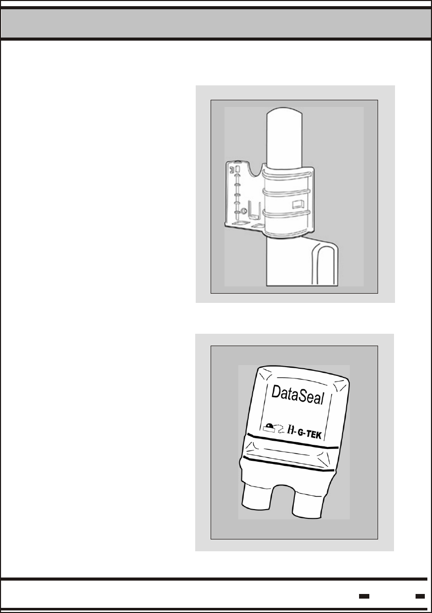
1.2.1. The Mounting Fixture
1.2.2. The Seal
The DataSeal Mounting
Fixture is used to mount
the DataSeal on the
container's keeper bar
or other surface.
The DataSeal unit
contains the DataSeal
electronics, a battery,
a transceiver, a
processor and memory
to record and store the
events and the
relevant information
about the cargo.
1
1.2. System Components
Introduction
Hi-G-Tek Ltd. Microelectronics & Asset Tracking Technology 19
1Introduction
Hi-G-Tek Ltd. Microelectronics & Asset Tracking Technology 20
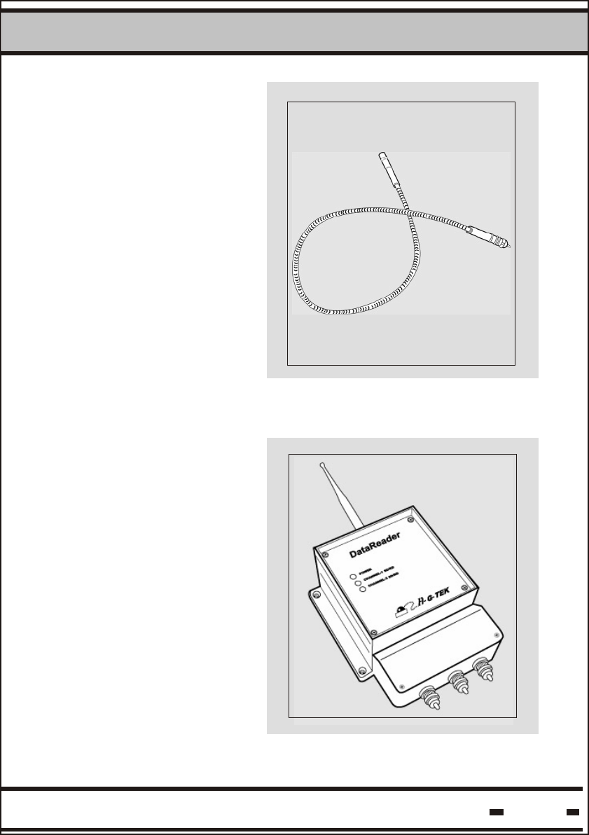
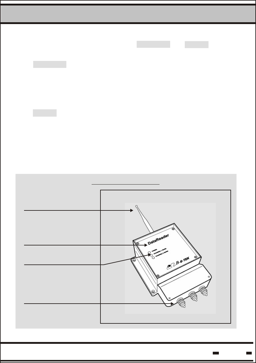
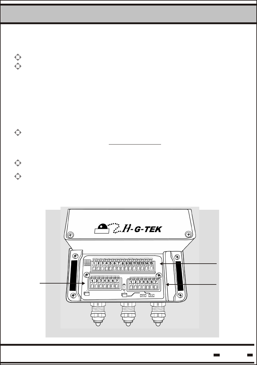
The DataReader is
comprised of two
compartments. The upper
compartment is the heart
of the unit and contains
the DataReader's
electronics section. The
lower compartment contains
the terminal glands which
connect the unit to the
networking cable.
1.2.3. Seal Wire
The DataSeal Wire serves
to seal the cargo.
Any tampering with the
DataSeal Wire at any
point during transport is
recorded and reported at
once.
1.2.4. Outdoor DataReader
The Hi-G-Tek DataSeal
System uses state-of-the
-art technology to
secure and monitor
secured cargoes in
storage and during
transport.
1Introduction
Hi-G-Tek Ltd. Microelectronics & Asset Tracking Technology 21
In the stationary configuration, the unit is mounted on a flat stationary
surface such as a wall or pole. A typical installation of this configuration
is at the point of exit from ports, customs terminals, warehouses, etc.
This operation mode allows monitoring of the seal at predetermined
sites and checkpoints.
In the mobile configuration, the unit is mounted in the truck cabin.
The DataReader monitors the seal during the entire journey, and reports
its status via the vehicle's communication system to the control center
in real-time.
The DataReader is mastered by a host computer. Once installed, the
unit waits for commands coming from the host computer.
The DataReader may be used in both stationary and mobile
configurations.
Upper Compartment:
Electronics Bay
Lower Compartment:
Cable Connection
Antenna
LED Indicators
Outdoor DataReader
1Introduction
Hi-G-Tek Ltd. Microelectronics & Asset Tracking Technology 22
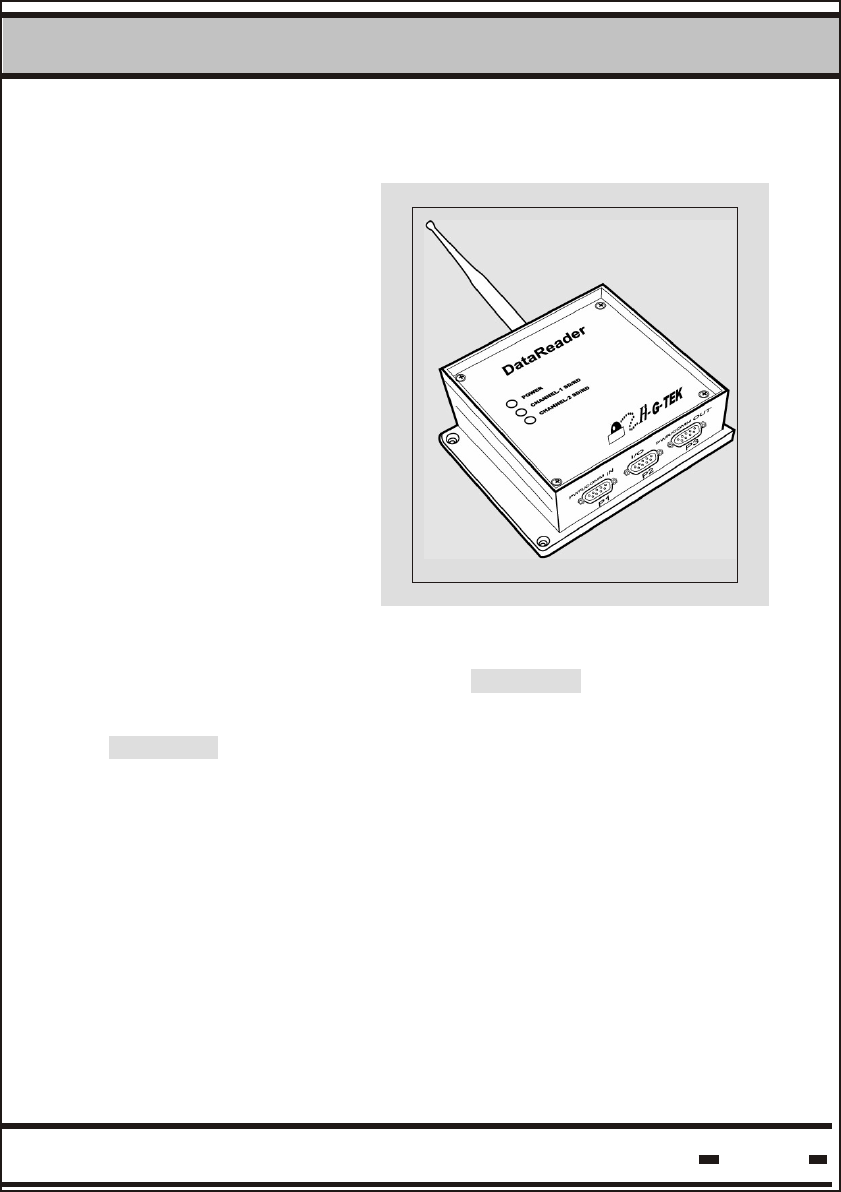
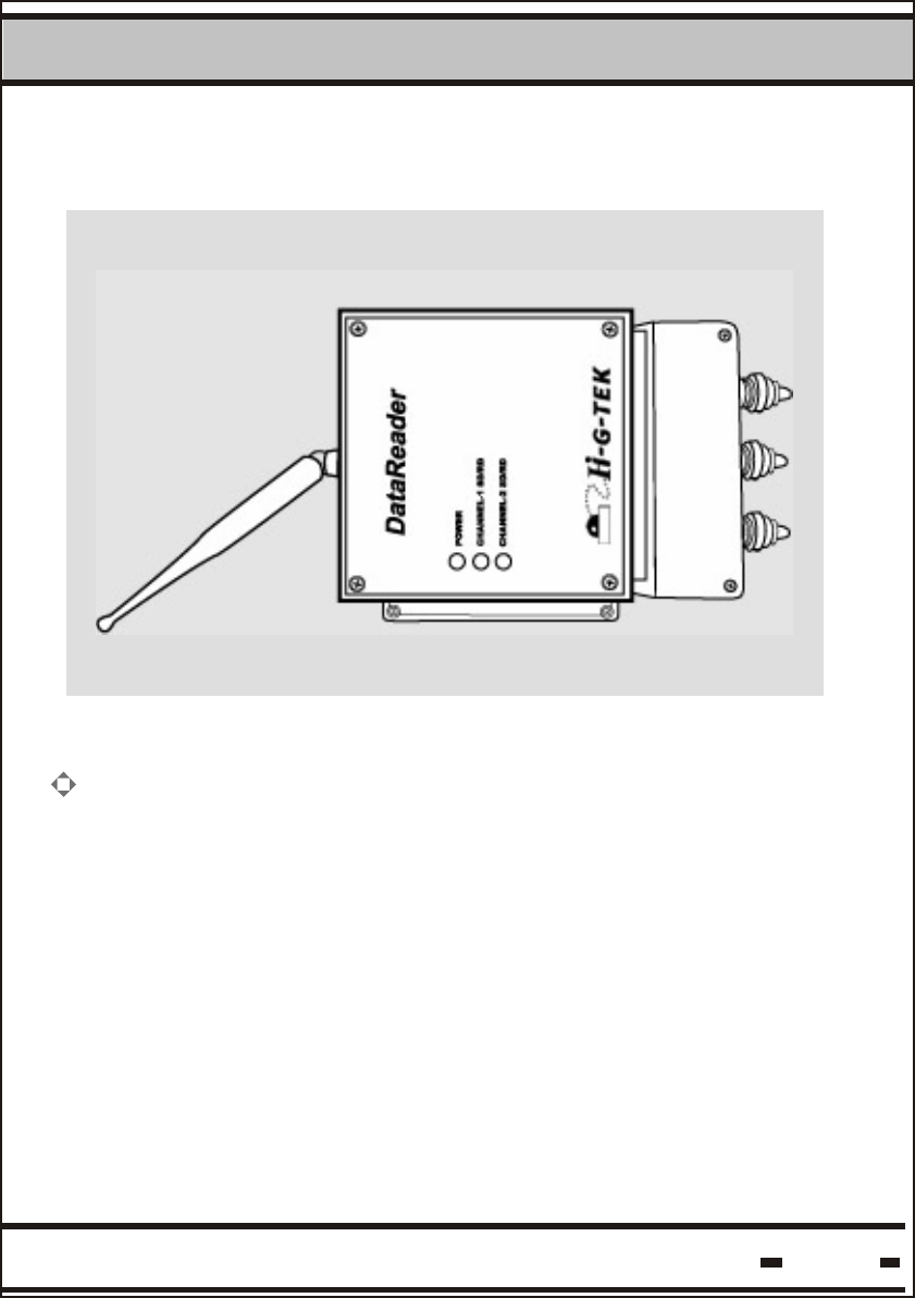
1.2.5. Indoor DataReader
Similar to the outdoor
version, the indoor
DataReader uses state-of
-the-art technology to
secure and monitor
secured cargoes in an
indoor environment.
In the stationary configuration, the unit is mounted on a flat surface
such as a wall or pole. A typical installation of this configuration
is at the point of exit from ports, customs terminals, warehouses, etc.
This operation mode allows monitoring of the seal at predetermined
sites and checkpoints.
The DataReader is mastered by a host computer. Once installed, the
unit waits for commands coming from the host computer.
The Indoor DataReader may be used in stationary configuration
only.
1Introduction
Hi-G-Tek Ltd. Microelectronics & Asset Tracking Technology 23
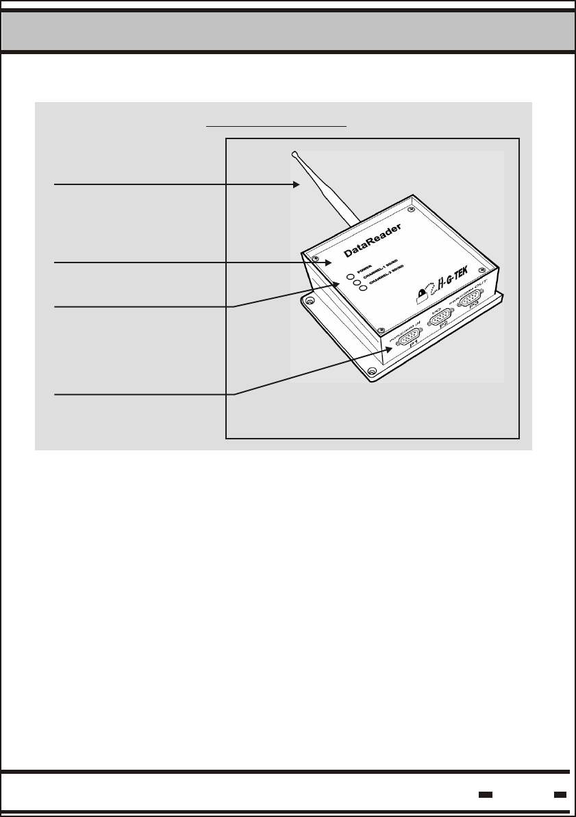
Electronics Bay
Cable Connection
Antenna
LED Indicators
Indoor DataReader

1Introduction
Hi-G-Tek Ltd. Microelectronics & Asset Tracking Technology 24

DataSeal
Installation
Chapter 2
2
Hi-G-Tek Ltd. Microelectronics & Asset Tracking Technology 26
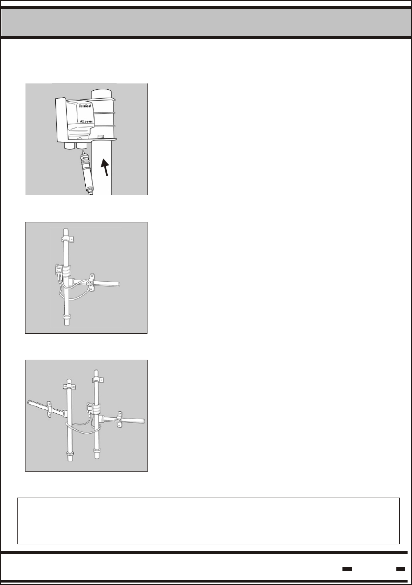
DataSeal Installation
step 1.
Fig. 1
Fig. 3
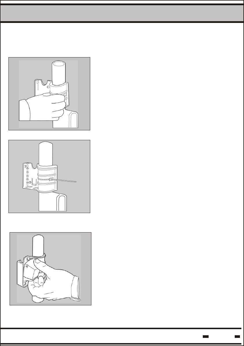
To install the DataSeal Mounting Fixture, attach
the fixture to the keeper bar at the back of the
container (fig.1). A click indicates that the
fixture is in place.
Fig. 2
0
To install the DataSeal, hold the unit at a 45
angle as illustrated and snap it into place in its
cradle on the DataSeal Mounting Fixture. (fig. 3)
step 2.
2.1 DataSeal Installation
The two side slots may be used to secure the
mounting fixture to the container, using
a 3-5mm width by 180-250 mm length
plastic strap (fig 2).
2
Hi-G-Tek Ltd. Microelectronics & Asset Tracking Technology 27
DataSeal Installation
Fig. 5
To connect the DataSeal Wire, simply attach
one end of the seal wire conectors to either of
the sockets at the base of the DataSeal (fig 4).
Fig. 4
Loop the wire through the container locking ring
and the keeper bar, then insert the end into
the other socket (fig. 5).
step 3.
Fig. 6
Alternatively, you may loop the wire through both
keeper bars then insert the end into the
other socket (fig. 6).
FCC ID: OB6-IGRS40916
This device complies with Part 15 of FCC rules. Operation is subject to the following two
conditions: (1) This device may not cause harmful interference, and (2) This device must accept
any interference that may cause undesired operation.

Hi-G-Tek Ltd. Microelectronics & Asset Tracking Technology 28

DataReader
Installation
Chapter 3
DataReader Installation
3
3.1 Outdoor DataReader Installation
3.1.1. Connecting the Outdoor Unit
The DataReader should be mounted on a smooth, flat surface.
To mount the unit, insert 4 screws into the slots on the unit and
fix to the surface.
A 6mm plastic anchor and 35mm pan head tapping screw
is recommended.
Remove the cover on the bottom portion of the DataReader unit
cover by removing the screws holding it in place.
Expose the wires in the cable and insert them into the terminal
blocks. Use a small screwdriver to push the wires in. Ensure wires
are inserted in the slots in accordance with the color scheme.
See section 3.4. of this manual for wiring information.
Hi-G-Tek Ltd. Microelectronics & Asset Tracking Technology 30
Remove the covers from the glands being used.
* Note: The electronics compartment panel should only be
opened by an authorised repair person. Unauthorized use
may result in loss of warrenty.
TB3
TB1
TB2
DataReader Installation
3
Hi-G-Tek Ltd. Microelectronics & Asset Tracking Technology 31
DataReader Ceiling Unit. Antenna is perpendicular to ceiling.
3.1.2 Ceiling Installation
The DataReader can be mounted on the ceiling.
In such cases it is requested to mount the antenna perpendicular
to the ceiling using a 90 connector.
0
3.1.3 Wiring the Outdoor DataReader
Hi-G-Tek Ltd. Microelectronics & Asset Tracking Technology 32
DataReader Installation
3
The DataReader may be connected to the network via three types of
serial communication:
RS485 Full Duplex1.
RS485 Half duplex.2.
RS232 (different model number)3.
According to the DataReader model in use, the serial connection
can be either RS232 or RS485 (see Technical Specifications).
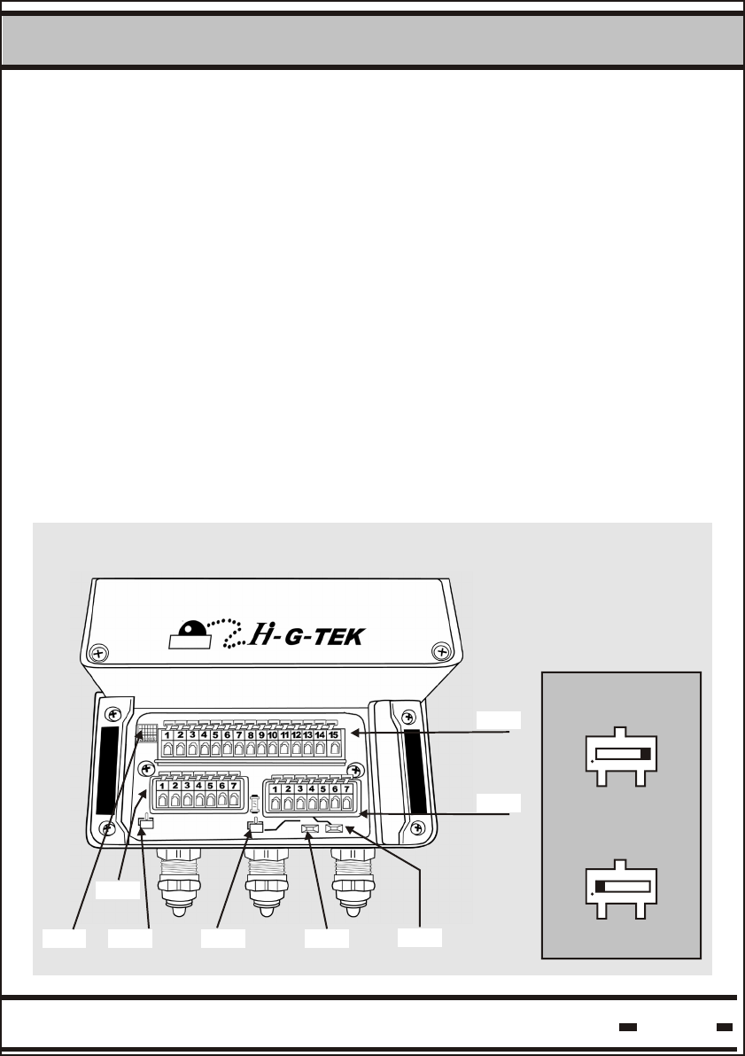
When the reader is connected using RS485, it can be set by the user
to full duplex mode or half duplex mode by altering the switch
configuration. For further information see sections 3.1.4.-3.1.6.
Switch Position
ON
OFF
TB3
TB1
S1 S4 S2 S6 S3
TB2
Hi-G-Tek Ltd. Microelectronics & Asset Tracking Technology 10
DataReader Installation
3
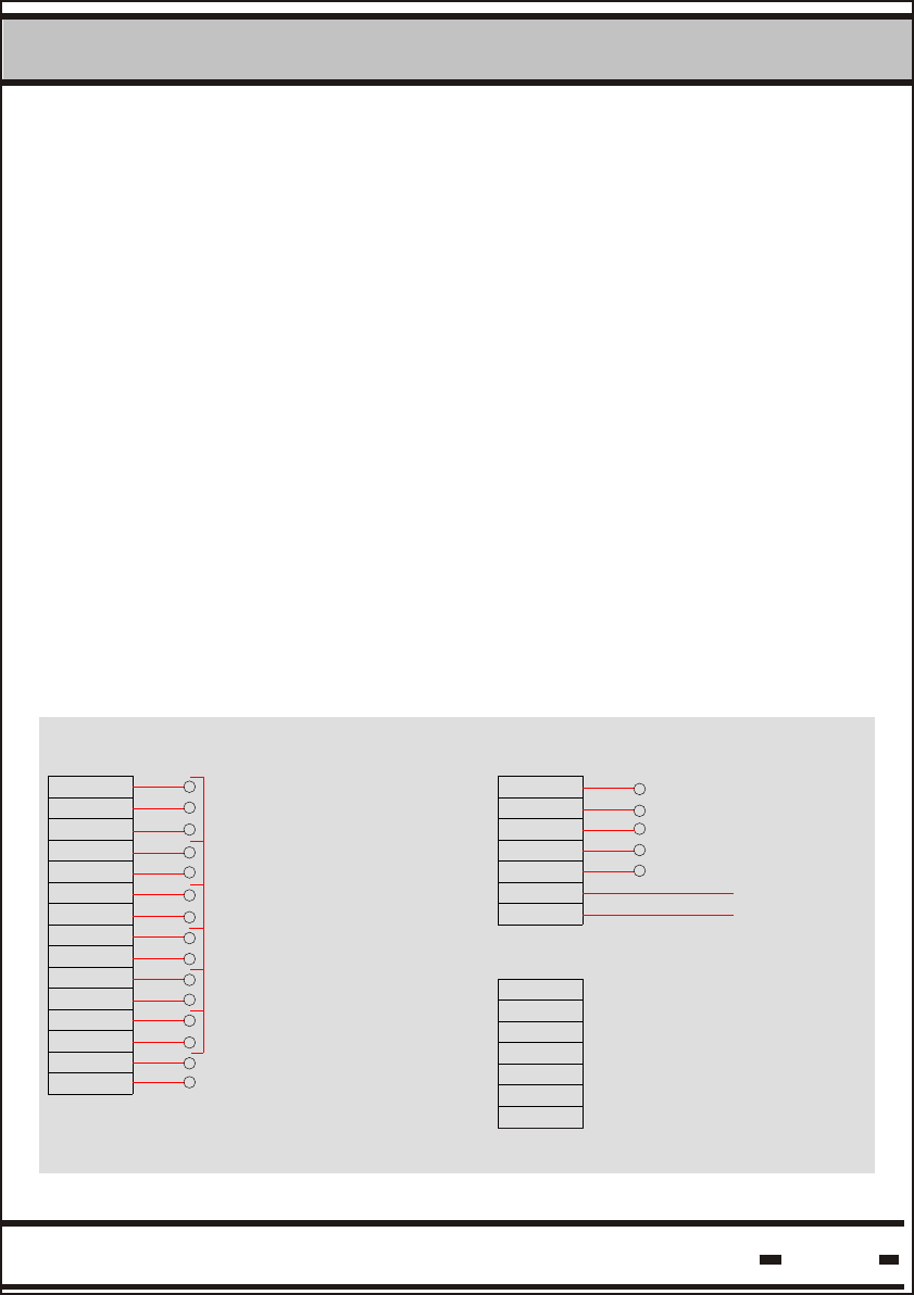
3.1.5. RS-232 Wiring Diagram
S1:
S2:
S3, S6:
S4:
3.1.4 DataReader Configuration Switches
Hi-G-Tek Ltd. Microelectronics & Asset Tracking Technology 33
DataReader Installation
3
+
3
1
2
CHASSIS GND
CHASSIS GND
9
6
4
5
7
8
10
11
14
12
13
TB3
15
DRY CONTACT OUTPUT
ISOLATED OUTPUT
ISOLATED OUTPUT
EXT.INTERRUPT INPUT
+
LED OUT
ISOLATED INPUT
-
+
-
-
+
+
-
NC
-
O
NO
POWER IN
RS232
TB1
READER TX
READER RX
SIGNAL GND
5
3
2
1
4
6
7
+
-
TB2
1
3
2
4
5
6
7
Reader configuration setup switch; Future use.
Default position: OFF.
Termination ON/OFF switch.
While ON, connects an internal 120 Ohm termination
resistor to the RS485 chain.
Default position: OFF
Full/Half duplex switches.
While OFF: Full duplex mode is set
While ON: Half duplex mode is set
Default position: OFF
Reader shut-down switch.
While OFF: Reader is active
While ON: Reader is not powered
Default position: OFF
Hi-G-Tek Ltd. Microelectronics & Asset Tracking Technology 34
DataReader Installation
3
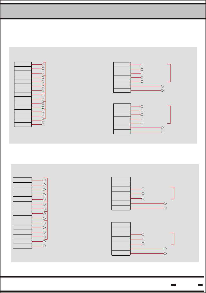
3.1.6. RS-485 FullDuplex Wiring Diagram
CHASSIS GND
1
2
3
4
5
6
7
8
9
10
11
12
13
14
15
TB3
CHASSIS GND
EXT.INTERRUPT INPUT
+
-
+
-
+
-
+
-
+
-
O
NC
NO
DRY CONTACT OUTPUT
ISOLATED OUTPUT
LED OUT
ISOLATED INPUT
ISOLATED OUTPUT
7
3
5
6
4
2
1+
-POWER IN
RXA
RXB
SIGNAL GND
TXA
TXB
RS485 IN
TB1
TB2
1
2
3
6
4
5
7
RS485 OUT
POWER OUT
SIGNAL GND
TXA
TXB
RXB
RXA
+
-
3.1.7. RS-485 Half Duplex Wiring Diagram
ISOLATED INPUT
8
2
1
5
3
4
6
7
EXT.INTERRUPT INPUT
CHASSIS GND
CHASSIS GND
LED OUT
+
+
-
+
-
10
9
13
12
11
TB3
15
14
ISOLATED OUTPUT
ISOLATED OUTPUT
DRY CONTACT OUTPUT
-
+
-
-
+
O
NO
NC
POWER IN
RS485 IN
POWER IN
TB2
TX/RX-A
TX/RX-B
SIGNAL GND
4
1
2
3
6
5
7
+
-
TB1
SIGNAL GND
TX/RX-B
TX/RX-A
1
2
3
6
4
5
7
+
-
RS485 OUT
DataReader Installation
3
Hi-G-Tek Ltd. Microelectronics & Asset Tracking Technology 35
3.2. Indoor DataReader Installation
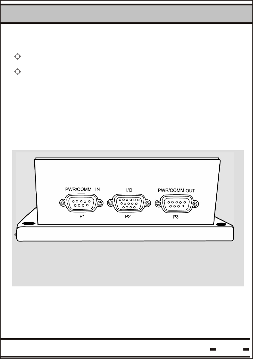
3.2.1. Connecting the Indoor Unit
* Note: The electronics compartment panel should only be
opened by an authorized repair person. Unauthorized use
may result in loss of warranty.
The indoor unit has three connector sockets at its base. Connector
socket P1 is for incoming communications and power-in. Socket
P3 is used to transfer power and to connect the unit to the next unit
in a daisy chain.
The DataReader should be mounted on a smooth, flat surface.
To mount the unit, insert 4 screws into the slots on the unit and
fix to the surface.
A 6mm plastic anchor and 35mm pan head tapping screw
is recommended.
DataReader Installation
3
Hi-G-Tek Ltd. Microelectronics & Asset Tracking Technology 36
DataReader Ceiling Unit. Antenna is perpendicular to ceiling.
3.2.2 Ceiling Installation
The DataReader can be mounted on the ceiling.
In such cases it is requested to mount the antenna perpendicular
to the ceiling using a 90 connector.
0
DataReader Installation
3
Hi-G-Tek Ltd. Microelectronics & Asset Tracking Technology 37
3.2.3 Wiring the Indoor DataReader
The DataReader may be connected to the network via three types of
serial communication:
RS485 Full Duplex1.
RS485 Half duplex.2.
RS232.3.
Each of the above is a different model number.
According to the DataReader model in use, the serial connection
can be either RS232 or RS485 (seeTechnical Specifications).
The RS485 connector is always optically isolated.
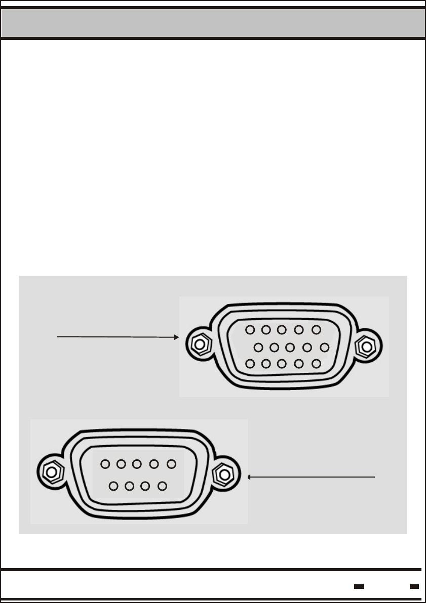
DB15
PIN Arrangement
DB9
PIN Arrangement
1
5
10 6
11
15
9
1
6
5
DataReader Installation
3
Hi-G-Tek Ltd. Microelectronics & Asset Tracking Technology 38
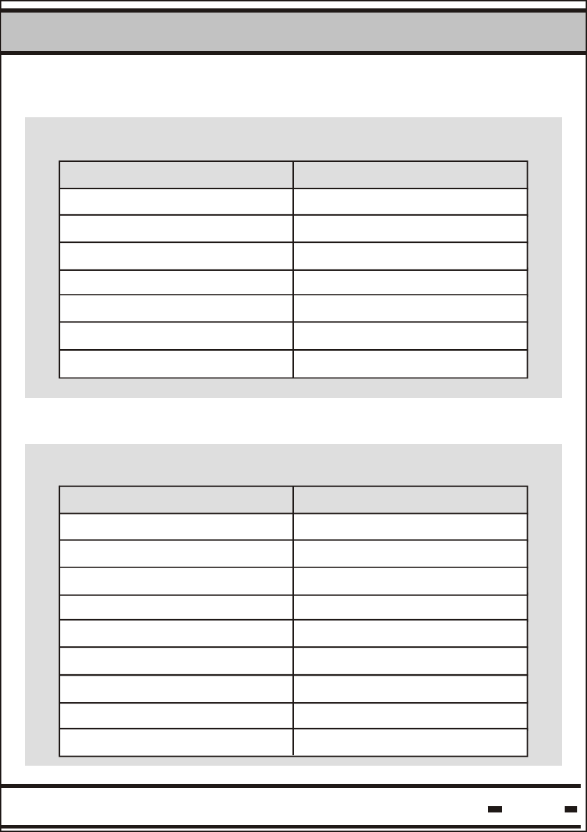
3.2.4. RS-232 Wiring Diagram
Pin assignment for PWR/COM IN & PWR/COM OUT
Function Pin Number
Positive Power
Positive Power
Signal GND
Negative Power
Negative Power
TX
RX
1
2
3
4
5
6
7
3.2.5. RS-485 FullDuplex Wiring Diagram
Pin assignment for PWR/COM IN & PWR/COM OUT
Function Pin Number
Positive Power
Positive Power
Signal GND
Negative Power
Negative Power
RX-A
RX-B
TX-A
TX-B
1
2
3
4
5
6
7
8
9
DataReader Installation
3
Hi-G-Tek Ltd. Microelectronics & Asset Tracking Technology 39
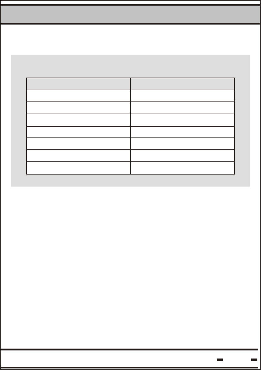
Pin assignment for PWR/COM IN & PWR/COM OUT
Function Pin Number
Positive Power
Positive Power
Signal GND
Negative Power
Negative Power
TX/RX-A
TX/RX-B
1
2
3
4
5
6
7
3.2.6. RS-485 Half Duplex Wiring Diagram

DataReader Installation
3
Hi-G-Tek Ltd. Microelectronics & Asset Tracking Technology 40
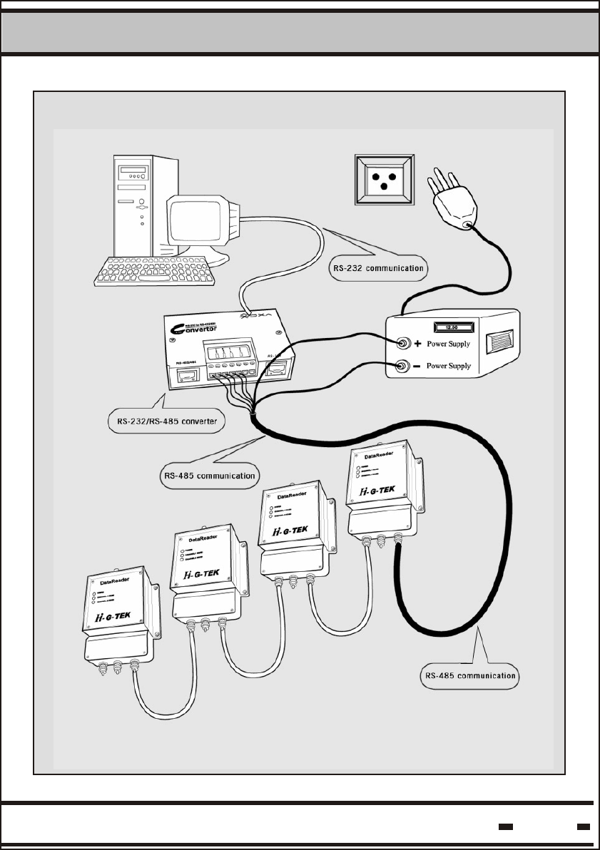
Up to 32 DataReaders can be connected in a daisy chain using
RS485. The last reader in the chain should be terminated by a
120 Ohm resistor between the RXA and the RXB.
For the Outdoor version, the user can decide to create either an
internal or external termination switch. The internal termination
switch is created by setting to ON the termination switch (S2) of
the last reader in the daisy chain.
An external termination is relevant for the Indoor version only. An
RS-485 to RS-232 adapter termination should be provided for the
adapter receive channel.
3.3. Chaining DataReaders Together
DataReader Installation
3
Hi-G-Tek Ltd. Microelectronics & Asset Tracking Technology 41
DataReader Installation
3
Hi-G-Tek Ltd. Microelectronics & Asset Tracking Technology 42
3.4. RS-232/RS-485 Adapter
Adapter's requirements:
- Full/Half duplex operation mode
- Isolated communication lines
Recommended adapter: Moxa Technologies, model A51
Adapter configuration: (refer to adapter's User Manual)
Default configuration of the Moxa A51:
1.
2.
3.
Communication mode (either half or full duplex)
Txd: always enable
Rxd: always enable
- Full Duplex mode
- Txd always enable
- Rxd always enable
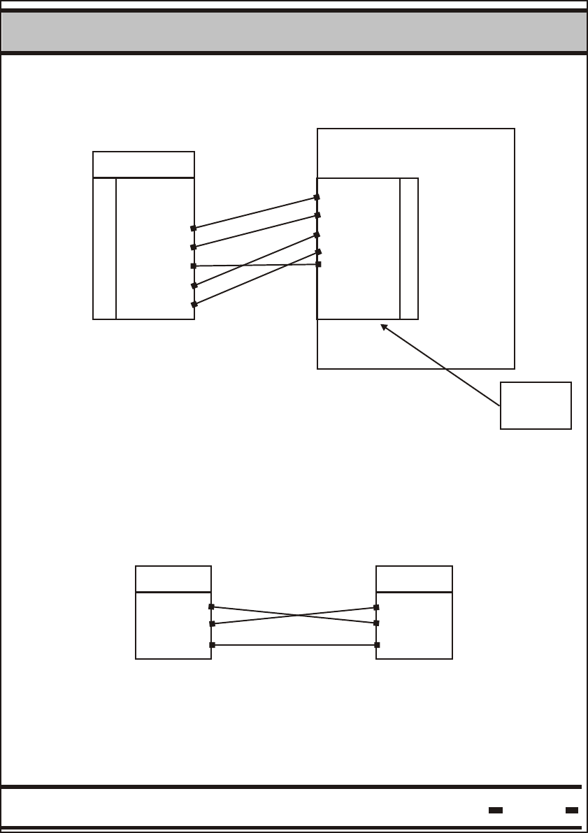
3.4.1. Connecting the RS-232/RS-485 Adapter to the First Reader
The Rx and Tx lines should be crossed between the adapter and
the first reader as follows:
Reader
RXA
RXB
TXA
TXB
SIG-GND
Reader
TXA
TXB
RXA
RXB
SIG-GND
DataReader Installation
3
Hi-G-Tek Ltd. Microelectronics & Asset Tracking Technology 43
Moxa A51 Wiring:
Reader TB1
PWR+
PWR-
RXB
RXA
GND
TXB
TXA
TXB
TXA
RXB
RXA
GND
PWR-
PWR+
Terminal
Block
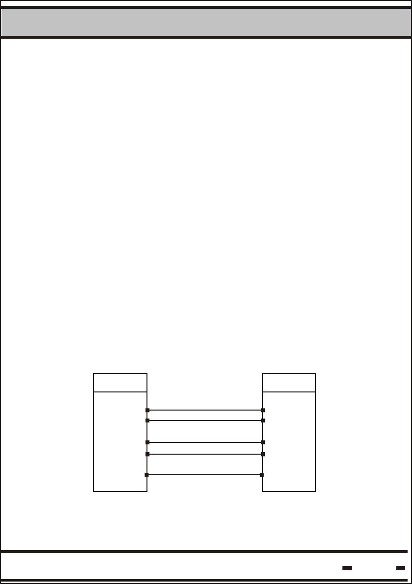
3.4.2. Connecting the RS-232/RS-485 Adapter to the Host
RS-323 3-wire connection should be performed between the
adapter and the host. (Other control signals beside the Rx, Tx and
GND are not required).
Adapter
Rx
Tx
GND
Rx
Tx
GND
Host
Rx and Tx should be crossed, as follows:
The Moxa A51 is connected to Host with RJ45/DB25 cable
supplied with the adapter. If the Host has a DB9 connector, a
DB25/DB9 adapter should be used.
MOXA
1
2
3
4
5
6
7
1
2
3
4
5
6
7

DataReader Installation
3
Hi-G-Tek Ltd. Microelectronics & Asset Tracking Technology 44
3.5. Power Supply Requirements
The DataReader supply voltage is chosen according to the
model, either 12V, 24V or 48V.
Power supply wattage: each Reader consumes maximum 1.7W,
so the power should tolerate the number of Readers in the chain
multiplied by each Reader's power consumption.
EXAMPLE: 10 Readers connected in a daisy chain require
10X1.7=17W power supply.
Note that if the power supply is installed in a high temperature
0
area (usually above 40 C), there is a derate in power supply
wattage. (Refer to power supply manual).
For safety reasons, power supply current should be limited to 3A.
Current limitation should be done internally in the power supply, or
externally with a 3A fuse.
In vehicular installation, a 1A fuse must be used.
In outdoor and indoor system, the power supply should be installed
indoor. For outdoor system, approved power supplies are:
For Indoor system, the power supply should be UL1950 approved.
A desktop style with IEC320 inlet is recommended.
When power supply cable ends are connected directly to system cable,
a proper isolation should be made. Using heat shrink tube is
recommended.
3.6. Cable Selection
The cable is used for power supply to Readers in a chain and for
RS-485 serial communication.
For most applications, 3 or 4 pairs of 24AWG shielded cable is
adequate.
The serial communication requires shielded twisted pair cable,
the power supply requires low ohmic resistance of the conductors.
DataReader Installation
3
Hi-G-Tek Ltd. Microelectronics & Asset Tracking Technology 45
Example:
A setup of 10 DataReaders with 20 meter 24AWG cable between
Readers and 24v supply to the first Reader
The ohmic resistance between Readers is 3.4 Ohms (20 meter
of supply and 20 meters of return). Calculating the voltage drop
across the lines gives 5v only, left to the last Reader in the chain.
This is below Reader specification of Reader minimum supply voltage.
Supply: Two main issues should be considered, max current
carrying capacity and wire resistance.
Max current capacity: For 24AWG cable , the jacket is heated at 1 C
at 0.1A current, max temperature is 80 C. So, this cable can carry a
max of 2A at 60 C. ( (80-60)*0.1 ).
This calculation should be done for the application specific
requirements.
Wire resistance: The voltage drop across the cable may cause
insufficient voltage to the last readers in chain. Calculation of voltage
drop in a certain setup should be done, in order to avoid this.
In most cases, the solution for such problems includes , connecting
a pair of wires for the supply ( 2 for supply and 2 for return), using
thicker cable, or using higher temperature rated cable.
Environmental considerations: In an outdoor installation ,the cable
should withstand all outdoor conditions, that is water proof,
temperature,ruggedness etc.
Cable connection:
1 pair for RXA and RXB signals.
1 pair for TXA and TXB signals
SIGNAL GND may be connected to shield or to a pair of wires
(shield connection is recommended, though it depends on the
noise level of the specific environment).
If two conductors are used for supply and return, the ohmic
resistance would be 3.4/2=1.7 ohm. The voltage to the last Reader
in the chain would then be 17v, well above the minimum voltage
required.
If you experience difficulty calculating the voltage drop across the
supply line, contact your distributor for assistance.

DataReader Installation
3
Hi-G-Tek Ltd. Microelectronics & Asset Tracking Technology 46
3.7. Installation notes
3.7.1 The DataReader is distributed to a commercial/industrial use
only, and cannot be sold to the general public.
3.7.2 Installation must be performed according to this user manual,
and by an authorized personnel only.
3.7.3 It is the responsibility of the installer to ensure that when using
the outdoor antenna kits in the United States (or where FCC rules
apply), only those antennas certified with the product are used.
The use of any antenna other than those certified with the product is
expressly forbidden in accordance with FCC rules CFR47 part
15.204."

DataReader
Operating
Instructions
Chapter 4
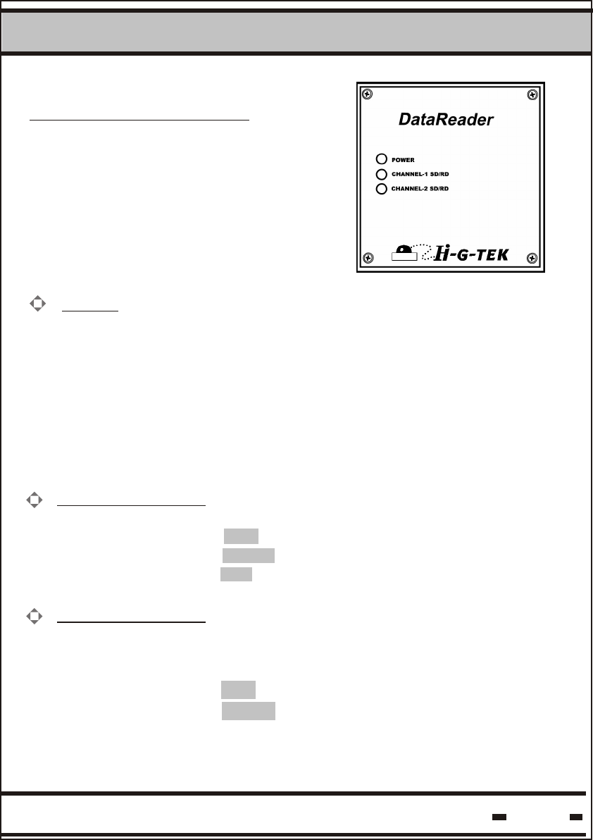
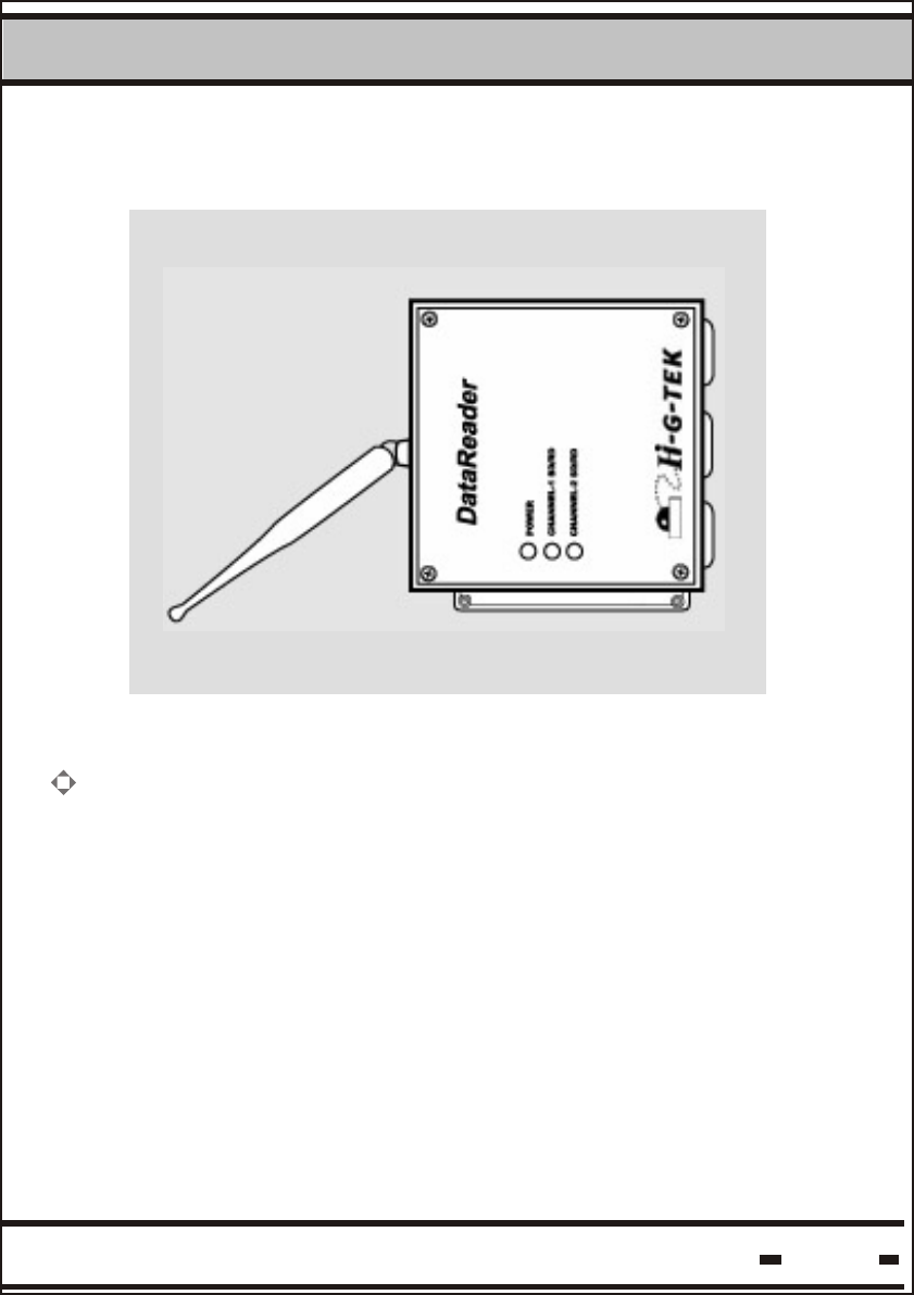
Hi-G-DataReader Operation
Three LED light indicators are located
on the left-hand side of the electronics
compartment.
Power: The DataReader is activated by connecting it to a power
supply. At power ON and self-test the power indicator alternates
between the GREEN and RED indicators for several seconds.
If the check result is OK, the indicator remains GREEN. If a
problem was detected, the indicator remains RED.
When performing firmware download:
- MCU download, the indicator alternates between GREEN
and RED
- AVR- the indicator remains off
Channel 2 SD/RD:
When the indicator is red, the unit is in SD (sending data) mode.
When the indicator is green, the unit is in RD (receiving data) mode.
When the indicator is off, it is in stand-by mode.
Channel 1 SD/RD:
This channel is optional. The indicators operate in an identical
manner to those for channel 2:
When the indicator is red, the unit is in SD (sending data) mode.
When the indicator is green, the unit is in RD (receiving data) mode.
DataReader Operation Instructions
4
Hi-G-Tek Ltd. Microelectronics & Asset Tracking Technology 48