Contents
Users Manual 3

Chapter 6
RS 485/232
Communication
Protocol

Hi-G-Tek Ltd. Microelectronics & Asset Tracking Technology 116
RS 485/232 Communication Protocol
6
6.1. RS- 485/232 Communication Protocol:
General Description
Communication between the Local Site Controller LSC and the
STAR READER is based on the master/slave approach. The LSC
is the MASTER unit, the READERS are the SLAVE units.
The LSC and the READERS communicate via a RS-485 multi
drop or RS-232 connection. Each READER has its own address,
enabling the LSC to approach each reader individually.
6.2. Physical Layer
6.2.1. Down-link
Down-link is the link from the LSC to the READERS. The link is
RS-485 or RS-232 half duplex. Data rate can be one of the
following: 2400, 4800, 9600, 19200, 38400 BPS. The default rate
is set at 9600 BPS.
6.2.2. Up-link
Up-link is the link from the READERS to the LSC. The link is
RS-485 or RS-232 half duplex. Data rate can be one of the
following: 2400, 4800, 9600, 19200, 38400 BPS. The default rate
is set at 9600 BPS.
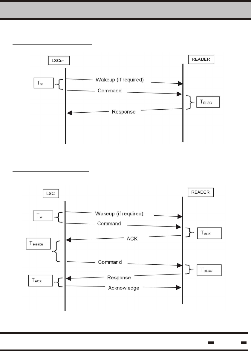
6.3. Protocol Flow.
Communication is initiated by a command sent by the LSC to the
READER. The READER executes the command and responds
accordingly. In a long command session, the session is concluded
when the LSC acknowledges the READER within T = 50 msec.
ACK
If the READERS are in sleep mode, the LSC must ensure they are
awakened prior to the initialization of the session. In this case, the
LSC should wait T = 50 msec before sending the main command.
w

Hi-G-Tek Ltd. Microelectronics & Asset Tracking Technology 117
6 RS 485/232 Communication Protocol
There are 2 types of commands: SHORT COMMANDS and LONG
COMMANDS.
Short Commands: These are commands that are relevant to
internal tasks at the reader level.
Long Commands: These commands involve sessions with seals.
The READER will respond to commands generated by the LSC
within T seconds.
RLSC
For short commands, response time should be: T = 50 msec.
RLSC
For long commands, the LSC should return to retrieve the results
after T with the appropriate GET RESULTS command.
session
T is a derivative of the type of command executed to the seals.
session
Acknowledge can be positive or negative.
If the LSC detects a problem, Acknowledge will be negative.
The READERS are designed to work in cycles. Following an
internal or external trigger, a READER SESSION is generated.
This is a full communication cycle going back and forth between
a READER and the tags located in the READER's receiving zone.
The LSC operates differently The READERs are scanned on a
different time line, using the same frequency as that of the
READER's cycles or greater.
This protocol supports RS-485 and RS-232 communication
fashions. When working with the LSC using RS-232 communication
opposite only one device, address fields should be set to 0xFFFF.
When using RS-485 communication in broadcast situations, the
address field should be set to 0x0000.
Hi-G-Tek Ltd. Microelectronics & Asset Tracking Technology 118
6 RS 485/232 Communication Protocol
Short Commands Mode:
Long Commands Mode:
Hi-G-Tek Ltd. Microelectronics & Asset Tracking Technology 119
6 RS 485/232 Communication Protocol
6.4. String Formats.
6.4.1. LSC to READERS messages.
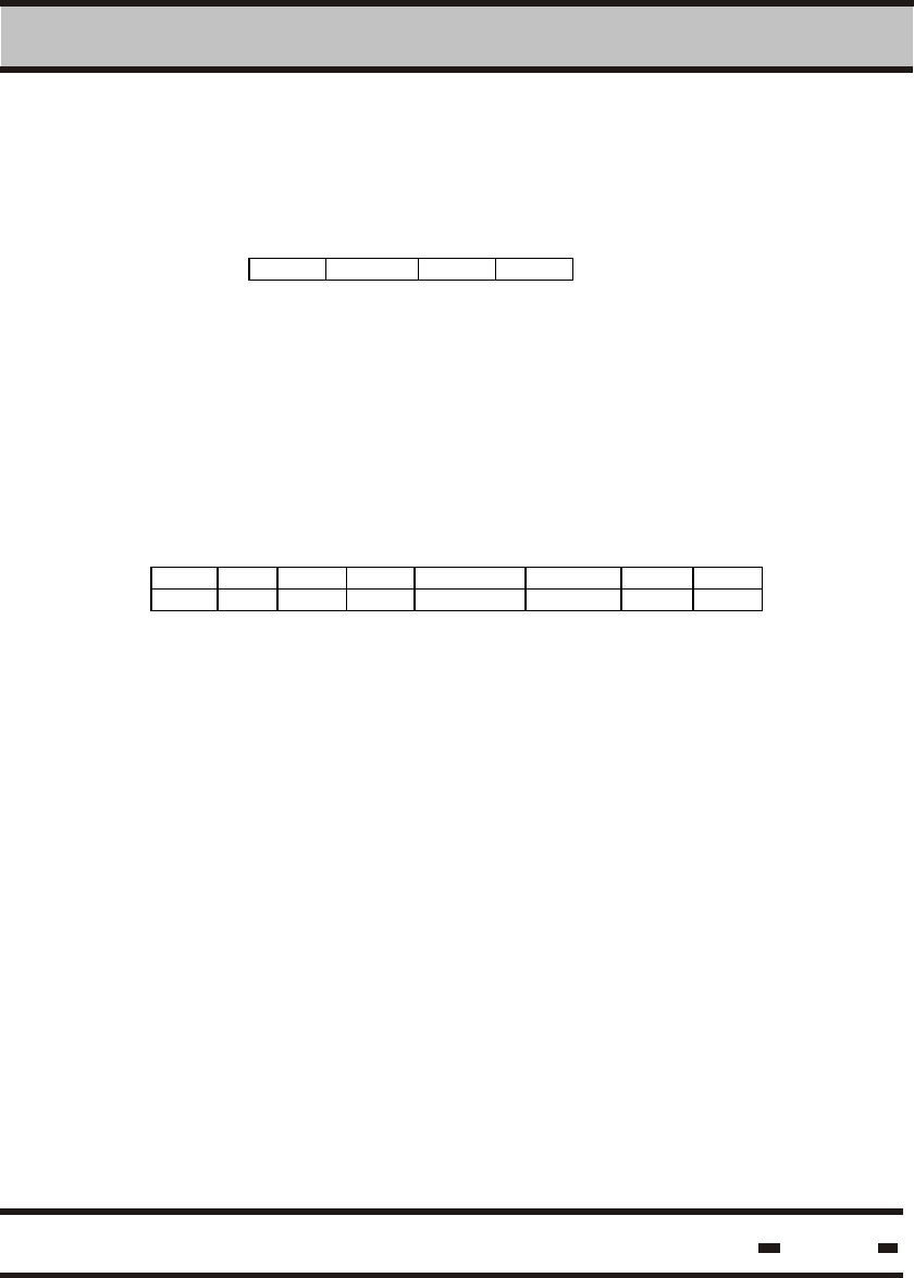
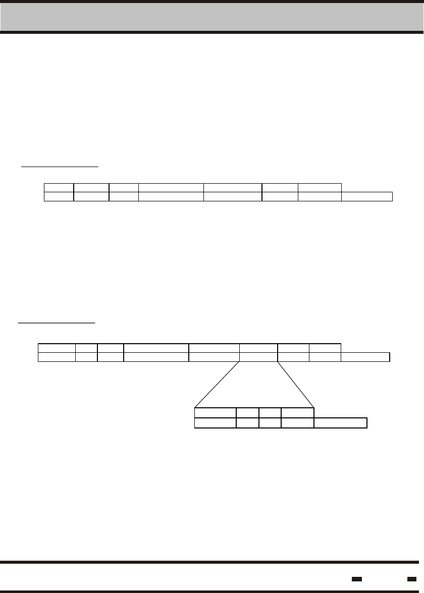
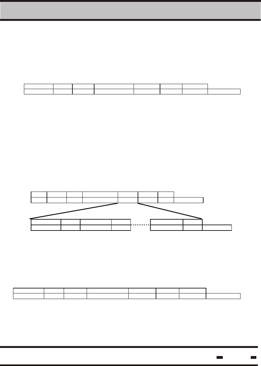
Commands & Acknowledge strings:
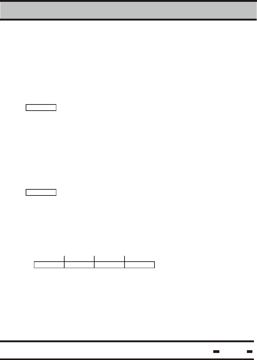
STX #B R# CMND data CRC ETX
1 2 2 2 n 2 1 # of bytes
#B
CRC
Where:
STX This is the marker for the beginning of the
messages. STX = 02 hex.
#B String length, the string contains the R#,CMND,
the DATA field, and the CRC.
R# This session's READER address .
CMND This session's command code .
DATA The data field contains the data required to execute
the command
CRC This is the cyclic redundancy check for DATA and
fields #B, R#, CMND.
ETX This is the marker for the end of the messages.
ETX = 03 hex.
6.4.1.1. CRC Calculation.
CRC calculations are based on the following CCITT polynomial:
16 12 5
X + X + X + 1
The result is 2 bytes.
Hi-G-Tek Ltd. Microelectronics & Asset Tracking Technology 120
6 RS 485/232 Communication Protocol
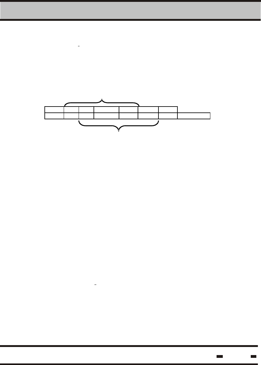
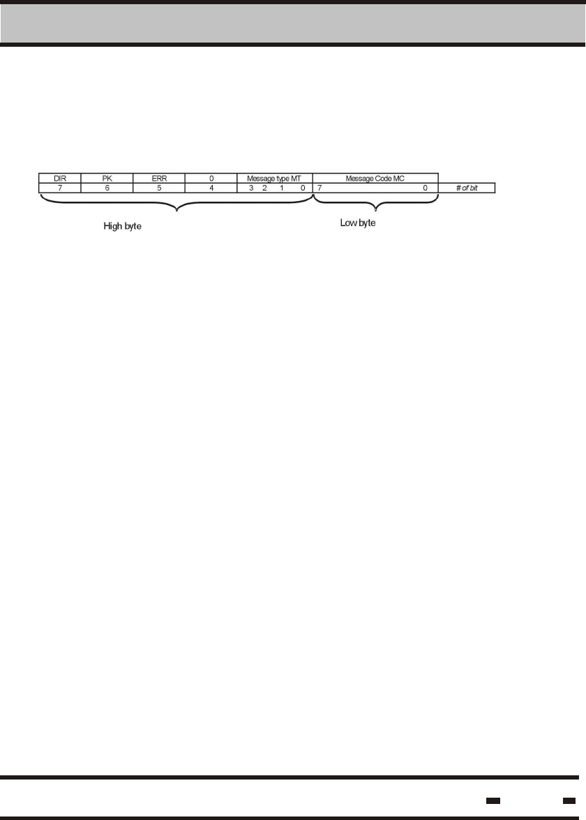
6.4.1.2. CMND Field Structure.
The command field is divided into several sections:
DIR Denotes string direction. In case of a command
from the LSC to the reader, it is equal to 0.
PK Denotes whether the command transmitted is
composed of packets or not. PK = 0 is for non-packet
commands. PK = 1 is for packet commands.
ERR this flag indicates an error.
ERR = 0 no error.
ERR = 1 Error. The first byte in the data field is the
error code.
CT Is the scenario command type. It describes the
Where:
command type, and whether it is in short or long form
00000 designates SHORT commands that stream
from the LCR to the Reader for MCU purposes.
00011 is for LONG commands.
This is the command code .
CC
Hi-G-Tek Ltd. Microelectronics & Asset Tracking Technology 121
6 RS 485/232 Communication Protocol
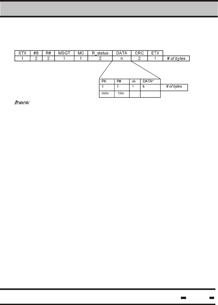
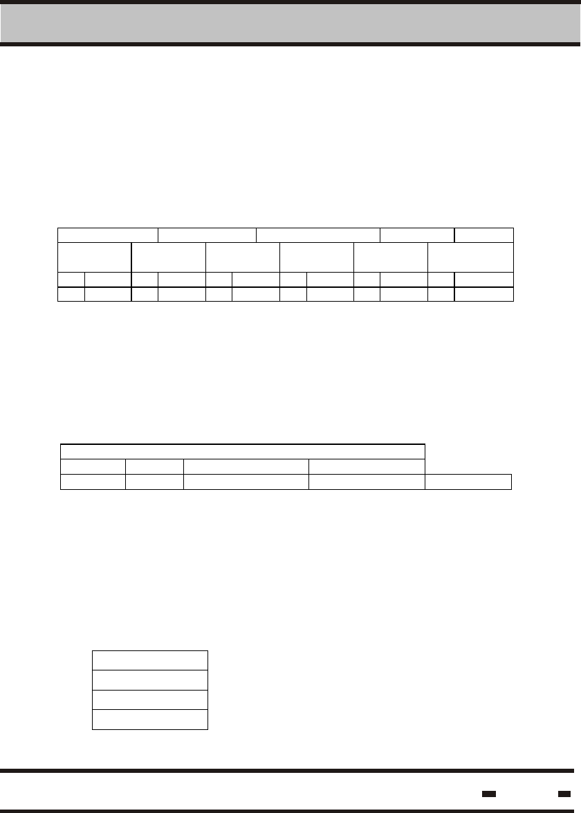
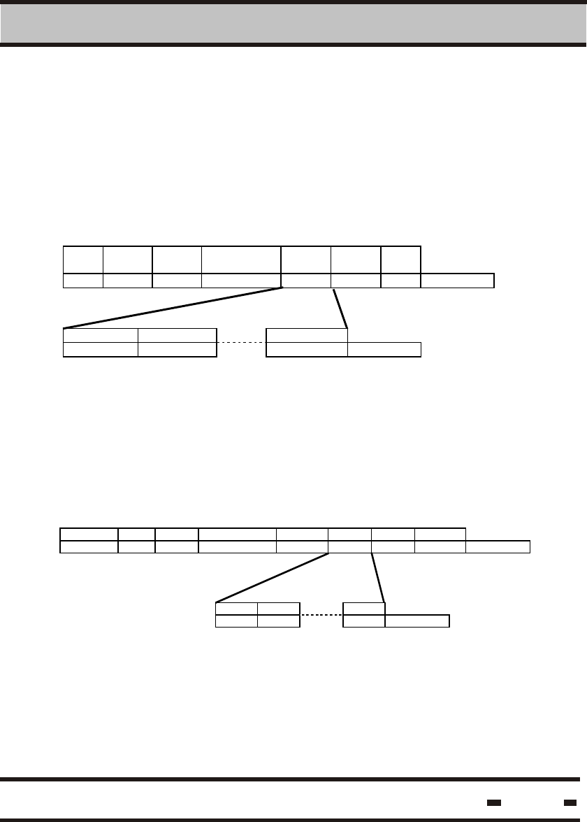
Response & Acknowledge strings:
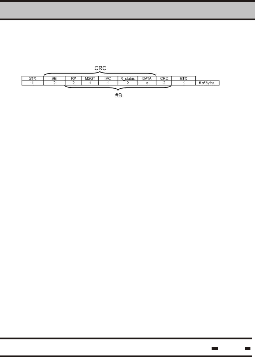
6.4.2. Reader to LSC Message
This is the marker for the beginning of the messages.
STX=02 hex.
String length, the string contains the R#, MSGT, MC,
R_status, the DATA field and the CRC.
This is the address of the READER for the current
session.
This is the message type response for the current
session. The MSGT corresponds to a specific
command (see paragraph 6.4.2.1)
This is the message code (see paragraph 5.2)
This is the status field of the reader. The field contains
bytes A&B (see paragraph 6.4.2.2)
The data field contains the relevant response data.
This is the cyclic redundancy check for fields #B,
MSGT, R_status and DATA.
This is the marker for the end of the messages.
ETX=03 hex.
STX
#B
R#
MSGT
MC
R_status
DATA
CRC
ETX
Hi-G-Tek Ltd. Microelectronics & Asset Tracking Technology 122
6 RS 485/232 Communication Protocol
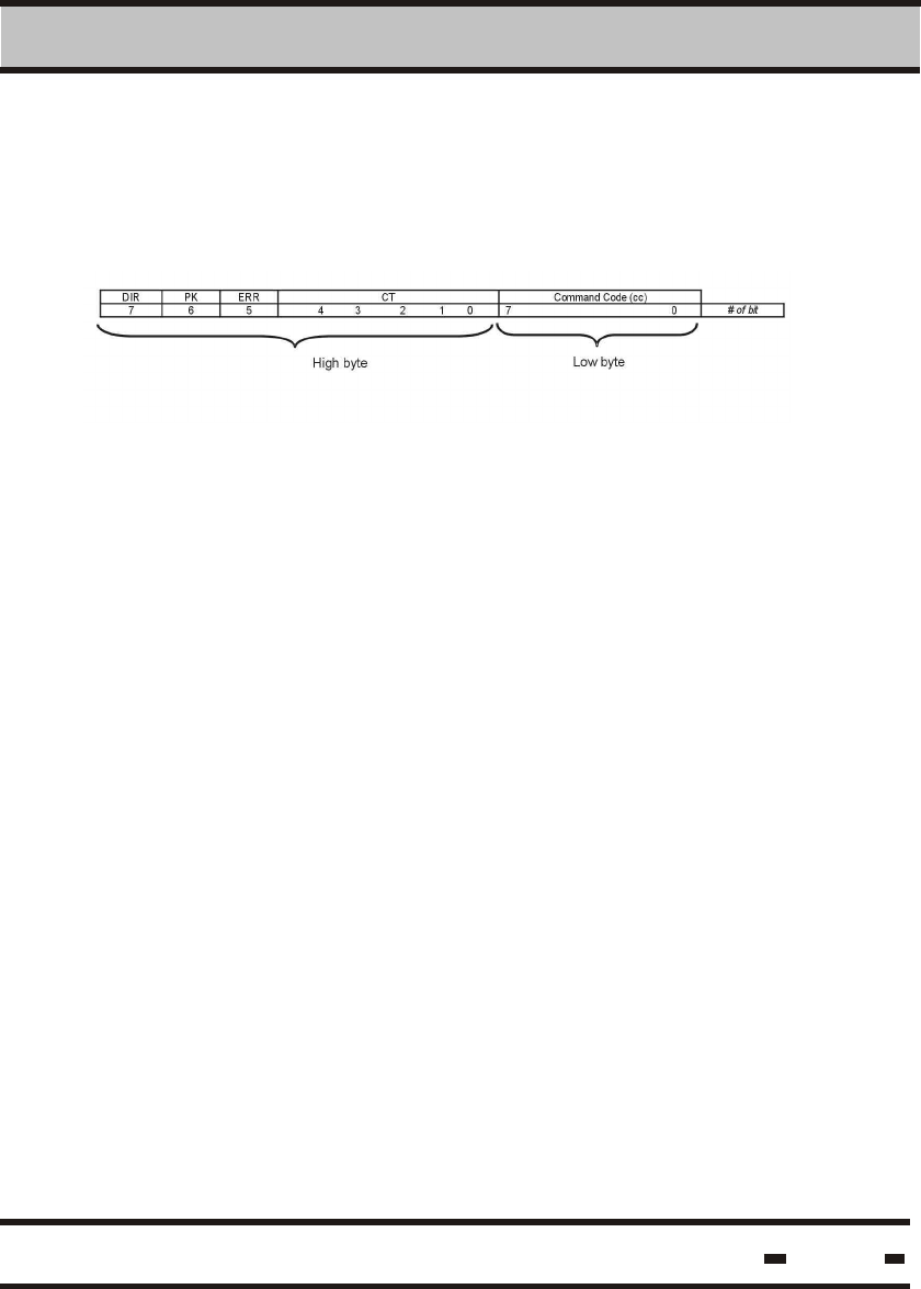
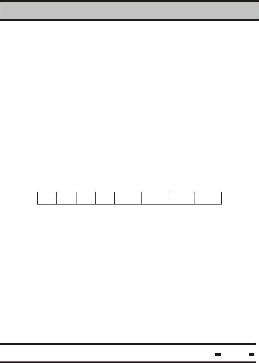
6.4.2.1. MSGT Field Structure.
The Message Type field is divided into several sections:
Where:
Is the string direction.Response will be 1.
DIR
PK
ERR
MT
MC This field holds the same value as the Command
Code of the related commands. This field makes it
possible to link the response to the appropriate
command.
This code reflects the nature of the response. A
regular response to a command has the same value
as the CC (See paragraph 6.4.1.2).
This flag indicates an error.
ERR = 0 no error.
ERR = 1 Error. The first byte in the data field stores
the error code.
Denotes whether the transmitted message is
composed of packets. A response of 1 indicates
that the message is composed of packets. If the
response is 0, the message was transmitted without
packets. (If PK=0 there must be 1 reserved data byte).
Hi-G-Tek Ltd. Microelectronics & Asset Tracking Technology 123
6 RS 485/232 Communication Protocol
6.4.2.2. R_Status Field Structure
The READER's STATUS field is 4 bytes.
Byte A Byte B Byte C Byte D
Byte A represents the status of the main motherboard MCU.
The other bytes represent the RF modems' status.
In a general Reader response the R-Status reply contains
bytes A&B only.
In a GET Status command, the reply contains all the R-Status
bytes.
Byte A:
7 6 5 4 3 2 1 0
LCK 485 PCR PER VCCERR VBERR PMC EDC
Where:
LCK
485
PCR
If the response shows 0, the READER's parameters
are locked.
If the response is 1, the READER's parameters
are unlocked.
If the response is 0, the READER is using RS-232
mode for communication.
If the response shows 1, the READER is using
RS-485 mode for communication.
If the response shows 0, the parameters in the MCU's
2
E ROM are OK.
If the reponse is 1, parameters were corrupted and
successfully restored.
Hi-G-Tek Ltd. Microelectronics & Asset Tracking Technology 124
6 RS 485/232 Communication Protocol
If the response is 0, the parameters in the
2
MCU's E ROM are OK.
If the answer is 1, parameters are corrupted.
If response is 0, internal power is OK.
If response is 1, internal power is faulty.
If response shows 0, internal battery is OK.
If response is1, internal battery is faulty.
If response is 0, program memory in the MCU is OK.
If response is 1, program memory is corrupted.
This flag indicates that a delayed command was
triggered and is in process.
PER
VCCERR
VBERR
PMC
EDC
Byte B:
7 6 5 4 3 2 1 0
Ch1 Ch2 Ch3 Ch4 Ch1err Ch2err Ch3err Ch4err
Where:
Ch1
Ch2
Ch3
Ch4
if 0 channel1 is not in use.
If 1 channel1 is in use.
Iif 0 channel2 is not in use.
If 1 channel2 is in use.
If 0 channel3 is not in use.
If 1 channel3 is in use.
If 0 channel4 is not in use.
If 1 channel4 is in use.
Hi-G-Tek Ltd. Microelectronics & Asset Tracking Technology 125
6 RS 485/232 Communication Protocol
Ch1err
Ch2err
Ch3err
Ch4err
If 0, channel is OK
If 1, channel is defective, details are in byte C. If
byte C flags are OK, there is a communication
failure with this channel.I
If 0, channe2 is OK.
If 1, channe2 is defective, details are in byte C.
If byte C flags are OK, there is a communication
failure with this channel.
If 0, channe3 is OK.
If 1, channe3 is defective, details are in byte D. If
byte D flags are OK, there is a communication
failure with this channel.
If 0, channe4 is OK.
If 1, channe4 is defective, details are in byte D.
If byte D flags are OK, there is a communication
failure with this channel.
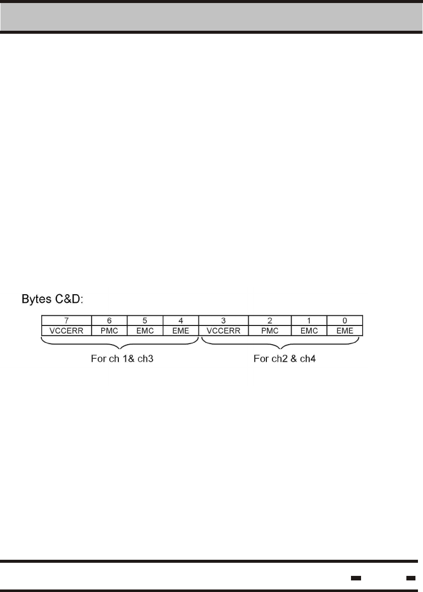
Bytes C&D:
VCCERR
PMC
EMC
EME
If 0, power is OK.
If 1, power is not faulty
If 0, program memory in the module is OK.
If 1, program memory is corrupted.
2
If 0, E ROM is OK.
2
If 1, E ROM was corrupted and then restored.
2
If 0, E ROM is OK.
2
If 1, E ROM was corrupted.
Hi-G-Tek Ltd. Microelectronics & Asset Tracking Technology 126
6 RS 485/232 Communication Protocol
6.4.2.3. Reader Messages Packed Data Format
Where:
PK
P#
Ch
The first byte is the total number of packets in
the string.
The second byte is the packet serial number.
The third byte is the channel number from which
the message is received.
Maximum total message length is 128 bytes.
Maximum Data* length is 115 bytes.
6.4.2.3.1. Packed Data from the LSC.
6.4.2.3.2. Packed Data from the READER.
When the packets originate with the LSC, each packet will be
transmitted after an appropriate response from the READER.
The LSC may retransmit the last packet upon receipt of a
response indicating that the last packet was not received
satisfactorily.
When the packets originate with the READER, each packet will be
transmitted after an appropriate acknowledgement from the LSC.
The READER may retransmit the last packet upon receipt of an
acknowledgment indicating that the packet was not received
satisfactorily
Hi-G-Tek Ltd. Microelectronics & Asset Tracking Technology 127
6 RS 485/232 Communication Protocol
6.5. LSC and Reader Messages.
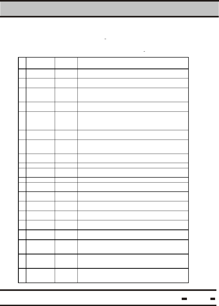
6.5.1. LSC Commands and Acknowledge Table:
# Commands
Set
Command
Code Comments
1 Wakeup E0 h This comm and wakens REA DERS it hat were in sl eep
mode.
2 Execute RF
cmnd
20 h This comm and generates an appropriat e comm and from
the READE R to the tags .
3 Get Results 15 h In a tag-reader sess ion, thi s com mand allows t he LSC to
retrieve the results received by the REA DER from the tags .
.
4 Get Status 16 h In case of a self-contained c ommand, t he READER will
return to it s current s tatus .
5 Get Burs t
Mess age
1C h This comm and should be us ed to retrieve the alert
mess ages retrieved from the seal s when using t he alert
burst mode. These are not available through the regular Get
Results .
6 Reset
Reader
14 h This comm and resets theREADER.
7 Write
Parameters
06 h This comm and modifies t he PARAM ETERS of a READE R.
After is suing a LOCK c ommand, not all the paramet ers are
accessible.
8 Read
Parameters
07 h This comm and is to read t he PARAM ETERS of a READE R.
9 BIT 09 h Exec utes a built in t est
10 Sleep 08 h This comm and puts t he READER int o the sleep m ode of
operation to enabl e power conservation.
11 Unsync Ack 0A h Reserved for the unsynchroniz ed response, see table 5. 2
12 Get Reader’s
baud rate
FF h This comm and allows t he LSC to obtain t he reader’s baud
rate.
13 Set Reader
baud rate
FE h This comm and allows t he LSC to s et the REA DER’s baud
rate.
14 Set Reader’s
Address
12 h This comm and sets the READE R’s address for RS-485
usage
15 Ack nowledge
OK
92 h This is an ac knowledgement of a mes sage com ing from a
READER.
16 Ack nowledge
Failed
94 h This is an ac knowledgement of an improper mess age
coming from a RE ADER.
17 Save
Command
0F h This comm and saves one of the above commands for lat er
execut ion. It is used to s ynchroniz e readers.
18 Exec ute
Saved
command
17 h This comm and execut es the c ommand saved in the
READER. When is used in a broadcas t fashion, all the
READERS execut e the com mand sim ultaneousl y.
19 Read
Channel
Definitions
11 h This comm and allows t he reading of channel definitions ..
20 Write
Channel
Definitions
10 h This comm and allows t he writing of channel defini tions.

Hi-G-Tek Ltd. Microelectronics & Asset Tracking Technology 128
6 RS 485/232 Communication Protocol
6.5.2. Message Table:
# Message Message
Code
Commen ts
1 Wak eup
response
- No response for WAKEUP st ring
2 Exec ute RF
cmnd res ponse
20 h
3 Get Results
response
15 h
4 Get Status
response
16 h
5 Get Burs t
Mess age
response
1C h
6 Reset Reader
response
14 h
7 Write
Parameters
response
06 h
8 Read
Parameters
response
07 h
9 BIT response 09 h
10 Sleep response 08 h
11 Unsynch
Mess age
0A h When a REA DER is i n unsync h mode, the RE ADER
may s end an unsync h mess age. This oc curs after
receiving an alert mes sage from a seal .
12 Get Reader’s
baud rate
response
FF h
13 Set Reader
baud rate
response
FE h
14 Set Reader’s
Address
response
12 h
15 Save
Command
response
0F h This comm and saves one of the above commands for
later exec ution. It is us ed to sy nchroniz e readers.
16 Exec ute Saved
command
response
_ This is a broadc ast c ommand. There is noresponse t o
this command.
17 Read Channel
Definitions
response
11 h This comm and allows t he reading of channel
definitions .
18 Writ e Channel
Definitions
response
10 h This comm and allows t he writing of channel definitions ..
Hi-G-Tek Ltd. Microelectronics & Asset Tracking Technology 129
6 RS 485/232 Communication Protocol
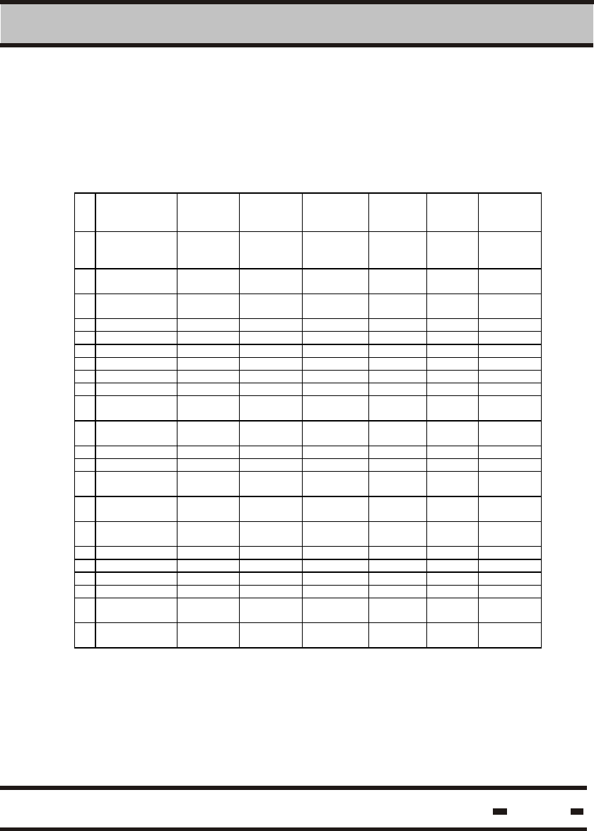
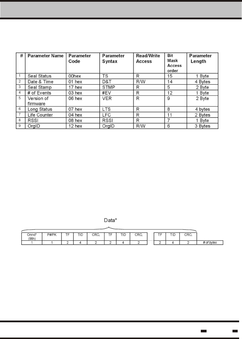
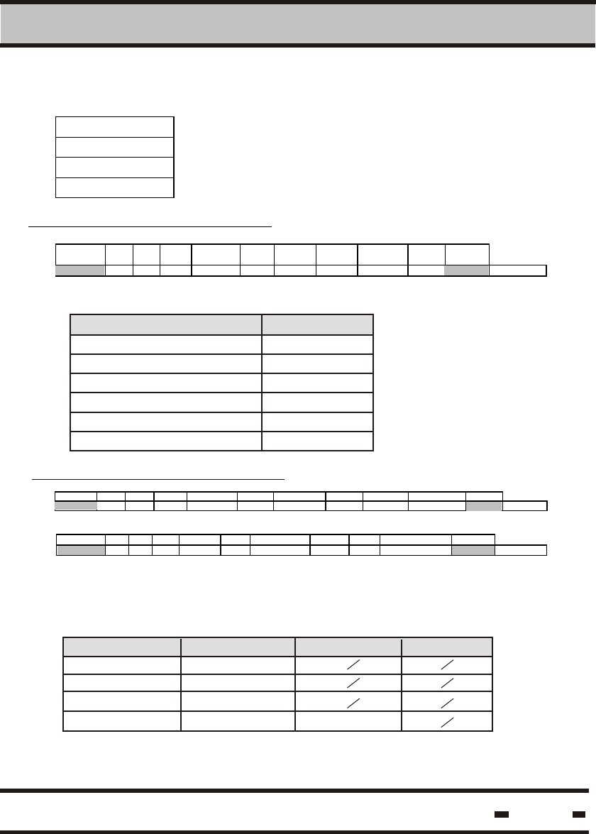
6.5.3. Parameters Table:
The following table relates to the Read and Write Parameters
Commands:
# Parameter
Name
Parameter
Code
Parameter
Syntax
Read/Write
Access *
Default
value
[unit]
Unit Parameter
length
1 Version of
MCU_firmwar
e
01 h MVER R 2 Byte
2 Version of
S1_firmware
80 h SVER1 R 2 Byte
3 Version of
S2_firmware
40 h SVER2 R 2 Byte
4 RSSI ch1 87 h RSSI1 R 1 Byte
5 RSSI ch2 47 h RSSI2 R 1 Byte
6 Reader ID 02 h RID R / 1 00000000 4 Byte
7 ADI ch1 81 h ADI1 R/W 00000000 4 Byte
8 ADI ch2 41 h ADI2 R/W 00000000 4 Byte
9 OrgID* 04 h OrgID R / 2 0000 2 Byte
10 Department
ch1
82 h DEP1 R/W 1 Byte
11 Department
ch2
42 h DEP2 R/W 1 Byte
12 Thw ch1 85 h Thw1 R/W 997 3.072ms 2 Byte
13 Thw ch2 45 h Thw2 R/W 997 3.072ms 2 Byte
14 Reader
Address
03 h RADD R/W 0000 2 Byte
15 Transmitter
Power ch1
88 h TRPOR1 R/W 65 1 Byte
16 Transmitter
Power ch2
48 h TRPOR2 R/W 65 1 Byte
17 System ch1 83 h SYS1 R/W ** 1 Byte
18 System ch2 43 h SYS2 R/W ** 1 Byte
19 Mode ch1 84 h MODE1 R/W 00 1 Byte
20 Mode ch2 44 h MODE2 R/W 00 1 Byte
21 Hard wakeup
ch1
86 h THP1 R/W 3256 3.072ms 2 Byte
22 Hard wakeup
ch2
46 h THP1 R/W 3256 3.072ms 2 Byte
* /1 or /2 defines the LOCK level.
Hi-G-Tek Ltd. Microelectronics & Asset Tracking Technology 130
6 RS 485/232 Communication Protocol
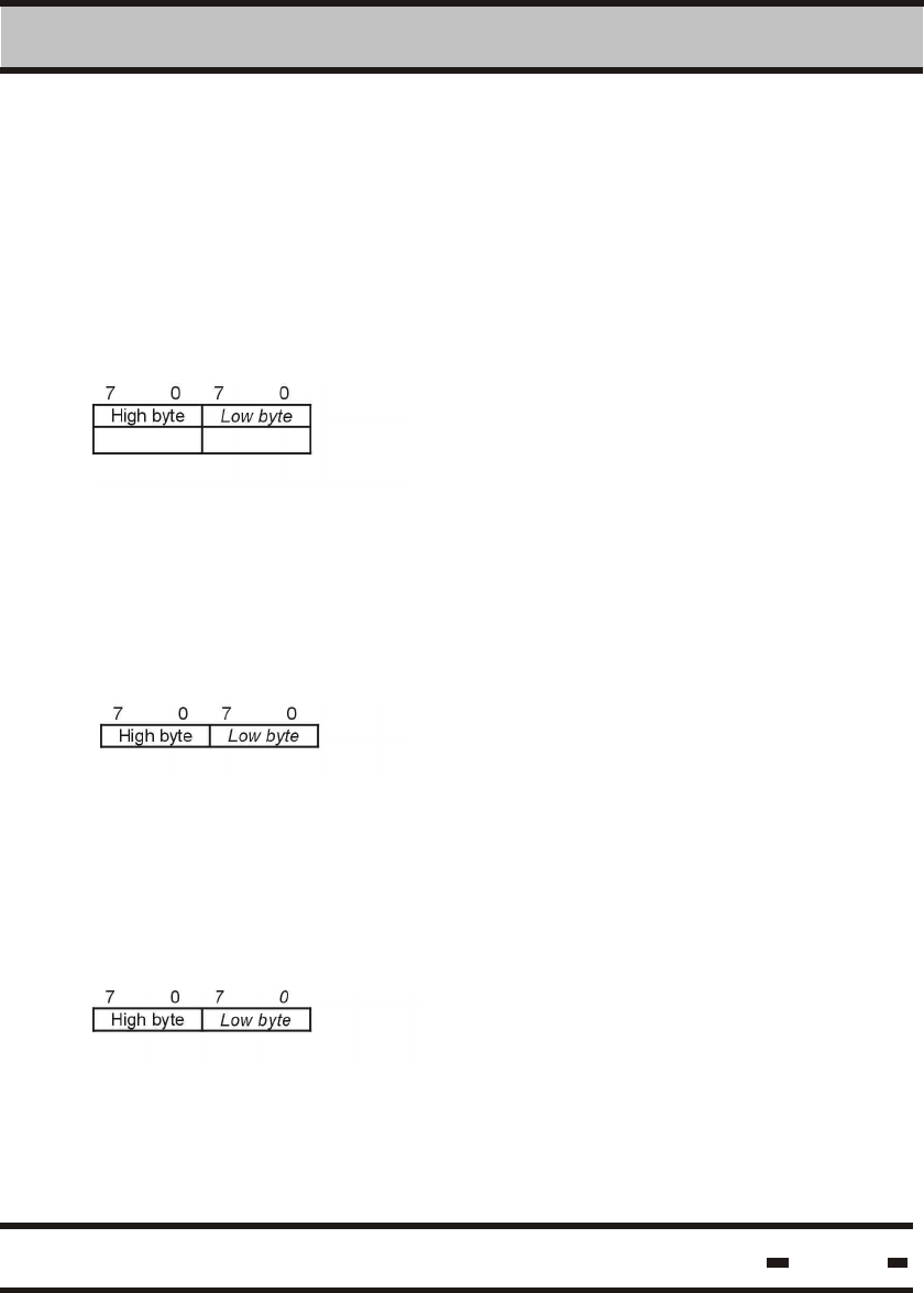
Parameters Format:
6.5.3.1. Reader Master Firmware Version MVER,
MVER is the version of the master firmware. This is a read only
parameter.
Bits assignment:
6.5.3.2. Reader Slave1 Firmware Version SVER1.
SVER1 is the version of the first slave's firmware.
This is a read only parameter.
Bits assignment:
6.5.3.3. Reader Slave1 Firmware Version SVER2,
SVER2 is the version of the second slave's firmware.
This is a read only parameter.
Bits assignment:
Hi-G-Tek Ltd. Microelectronics & Asset Tracking Technology 131
6 RS 485/232 Communication Protocol
6.5.3.4. Reader's receives signal strength RSSI1,
RSSI1 is the amplitude of the received signal from the READER
at the first channel. This value indicates the link's properties to
the READER and the system.
Bits assignment:
7 0
1 byte
Reader's receives signal strength RSSI2,
RSSI2 is the amplitude of the received signal from the READER
at the second channel. This value indicates the link's properties
to the READER and the system.
Bits assignment:
7 0
1 byte
6.5.3.5. Reader ID RID,
This is a Reader's ID.
Bits assignment:
7 0 7 0 7 0 7 0
High byte Mid byte Mid byte Low byte
Reader and Seal IDs format are identical. For additional information,
see paragraph 5.3.2.
Hi-G-Tek Ltd. Microelectronics & Asset Tracking Technology 132
6 RS 485/232 Communication Protocol
Bits assignment:
Bits assignment:
6.5.3.6. Group Access Identifier ADI.
The identifier allows the READER to access groups that conform
to this value.
7 0 7 0 7 0 7 0
High byte mid byte mid byte Low byte
6.5.3.7. Organization identifier OrgID*,
This is the end user's identifier. This parameter is used to
segregate between companies.
7 0 7 0
High byte Low byte
6.5.3.8. Department DEP
This is the customer's department identifier. This parameter is
used to segregate between departments within a company.
Bits assignment:
7 0
High byte
* See paragraph 5.3.3.
* See paragraph 5.3.3.
Hi-G-Tek Ltd. Microelectronics & Asset Tracking Technology 133
6 RS 485/232 Communication Protocol
6.5.3.9. Reader IH length Thw
This is the Reader's IH string length. The values may be modified
for a specific application.
Bits assignment:
Bits assignment:
7 0 7 0
High byte Low byte
6.5.3.10. Reader Address RADD.
This is the Reader's address on the RS-485 link. For RS-232, the
value is 0xFFFF
7 0 7 0
High byte Low byte
6.5.3.11. Mode MODE.
The MODE parameter determines the operating mode of the
Reader. Each bit indicates another feature.
7 6 5 4 3 2 1 0
CRNC UNSYNC ABMSG N.A N.A N.A N.A N.A
CRNC Carrier Sense: In some applications, carrier sense
must be used before bursting into the air.
The Reader uses this flag to decide whether it is
required or not.
CRNC=0 This response determines the regular
mode (no carrier sense).
CRNC=1 This response determines that the Reader
can sense the carrier. The Reader will execute the
RF command only after determining that the air is
free.
Hi-G-Tek Ltd. Microelectronics & Asset Tracking Technology 134
6 RS 485/232 Communication Protocol
UNSYNC In the unsynchronized commands such as
Unsynchronized Alert, the Reader's receiver
must be ON at all times, waiting for incoming
messages from the seals. The mode will be
set according to the flag's value:
UNSYNC=0 Synchronized mode only.
UNSYNC=1 Unsynchronized mode in use,
receiver should be set to ON.
ABMSG Burst Messages. This flag indicates whether the
alert messages will be sent following Alert GET
Results, or whether the Reader will burst
independently with Alert Messages.
BRMSG=0 determines the independent messages
burst mode.
BRMSG=1 indicates the Alert GET Results mode.
6.5.4. Error Codes
See paragraph 6.4.2
Errors Error C ode
Unrecognized Command 01 h
MCU Error 02 h
HF Modem Error 03 h
Result is not ready 05 h
HF Modem is not responding 06 h
MCU I/O Error 07 h
HF Modem BIT Error 08 h
Parameter is locked 09 h
Illegal Parameter Code 0A h
* Error codes appear in the data field
Hi-G-Tek Ltd. Microelectronics & Asset Tracking Technology 135
6 RS 485/232 Communication Protocol
6.5.5. Detailed Commands.
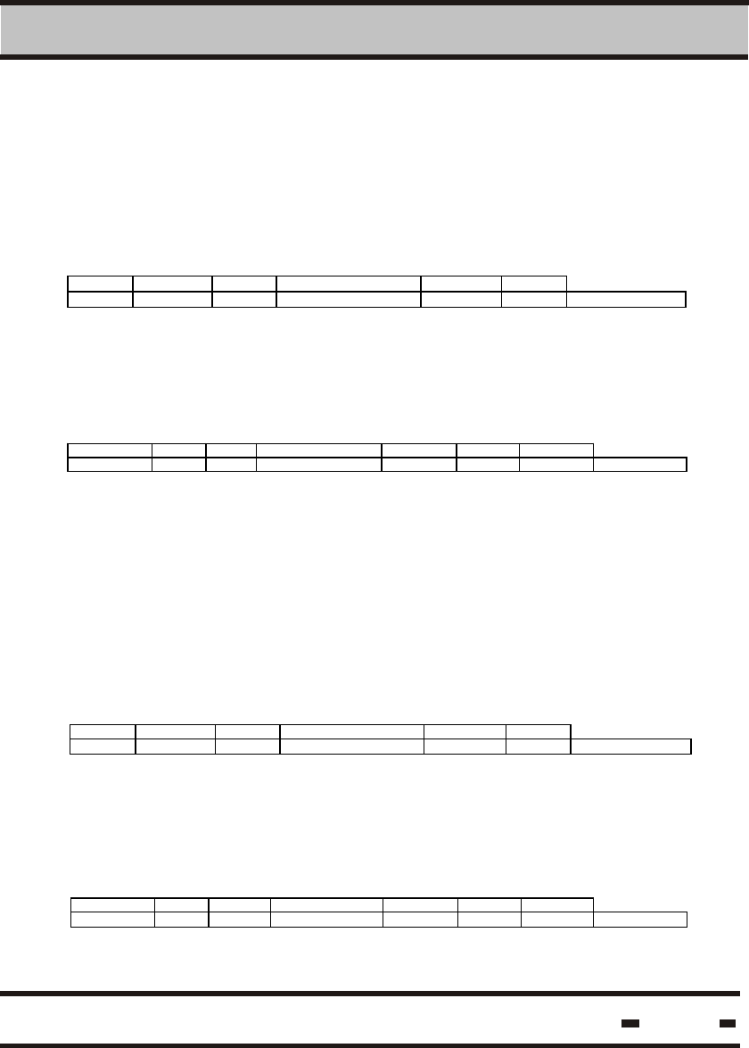
6.5.5.1. Wakeup
6.5.5.1.1. Command Transmission
6.5.5.2.1. Command Transmission
6.5.5.1.2. Wakeup Response
To wake a READER in sleep mode, a very short string must
be sent by the LSC. This will be detected by the hardware and
will awaken the READER. As this is a hardware-oriented command,
the format is different then all the other commands.
LSC > Reader
A WAKEUP string transmission wakens the READER. The READER
does not respond to such a string. After the command is issued the
READER is ready to receive regular commands.
6.5.5.2. Execute RF Command.
This command enables communication sessions with the seals.
The LSC inserts the relevant information in the data field allowing
the reader to easily compile the final command string.
LSC > Reader
Hi-G-Tek Ltd. Microelectronics & Asset Tracking Technology 136
6 RS 485/232 Communication Protocol
Where the channel field is one of the following:
Channel Code
Cha nnel 1 01 h
Cha nnel 2 02 h
ADI This parameter allows the User to subgroup seals.
If the response indicates 0,the Reader uses its internal
value for ADI. If not, this is the value which will be
transmitted to the seals.
Time&Date are the current Time and Date of the LSC.
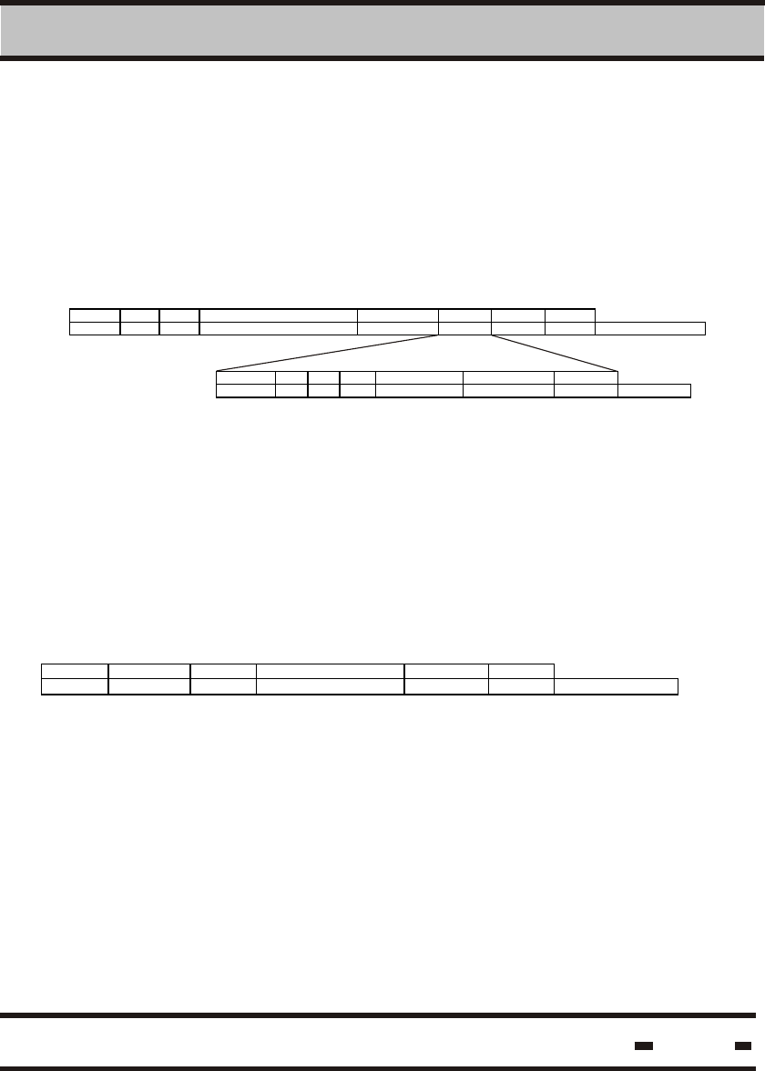
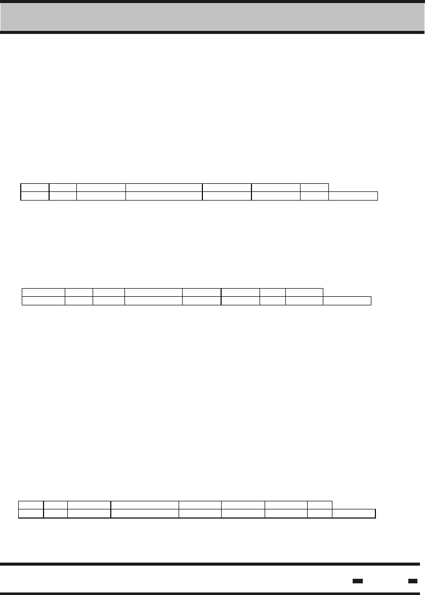
6.5.5.2.2. Execute RF Command ACK.
This command involves a RF session with either the tags or seals.
For that reason, the READER carries a Long Command. The
READER responds with an ACK if the command was successfully
received.
Reader > LSC
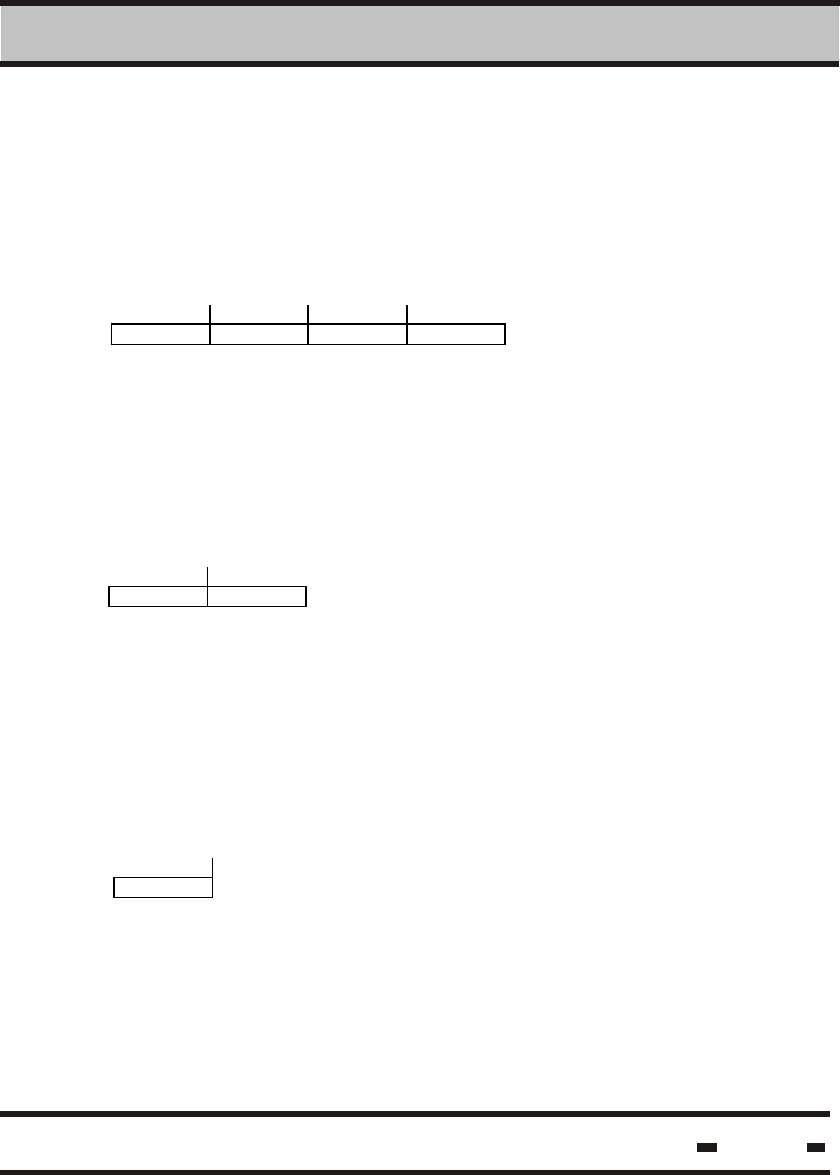
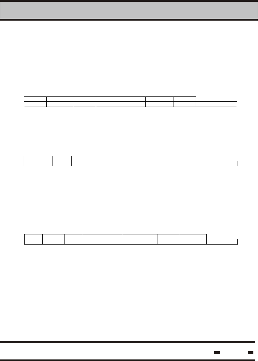
STX #B R# MSGT(XX20h) R_status channel CRC ETX
1 2 2 2 2 1 2 1 # of bytes
In case of an ACK with an error response:
STX #B R# MSGT(XX20h) R_status Err code CRC ETX
1 2 2 2 2 1 2 1 # of bytes
The final results of this command will be ready later. The LSC
should use the GET RESULTS command to retrieve the results.
For detailed error codes see para 5.4.
NOTE: In the Data Field, #B includes the Time & Data and ADI fields.
Hi-G-Tek Ltd. Microelectronics & Asset Tracking Technology 137
6 RS 485/232 Communication Protocol
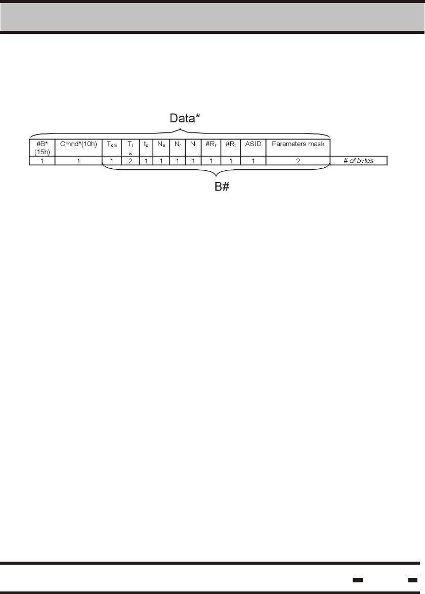
6.5.5.2.3. Verify.
The Verify command is carried through the high frequency modem.
The data field in the Execute RF Command will be:
Where:
#B
Cnmd*
Tcm
Tiw
Ts
Na
Nr
Nt
#Rr
#Rt
ASID
Parameters
Mask
is the number of bytes in the string from the Cmnd*
field up to the ADI field.
is the opcode of the RF command.
The duration of the calibration message window.
Resolution is in units of 1024 msec.
The duration of the READER interlace window.
Resolution is in units of 1024 msec.
The duration of a slot for receiving responses from
a tag or a seal. Resolution is in units of 1024 msec.
The number of slots in the Fixed Assignment
Receiving Window.
The number of slots in the Random Access
Receiving Window.
The number of slots in the Alert Receiving Window.
The number of random retransmissions from a tag
in the Random Access Receiving Window.
The number of random retransmissions from a tag
in the Alert Receiving Window.
Is a random unique ID that is assigned to a specific
assignment. For details see Assign commands.
Is the parameters bit mask to which the tags and
seal respond.
This is the interrogation cycle for reading short messages from tags
and seals. Tw wakes the tags in random phase.
Hi-G-Tek Ltd. Microelectronics & Asset Tracking Technology 138
6 RS 485/232 Communication Protocol
Bit Mask should comply with the following table:
6.5.5.2.4. Tamper
6.5.5.2.5. Set
The Tamper command is intended solely for interrogation of
tampered Seals. This command is identical to the Verify command
except for the opcode which is 11h.
In accordance to this, only Seals that have detected tamper status
will respond. The aim of this command is to provide high priority to
tampered Seals in a crowded Seal environment.
Set command is a command used when it is necessary to approach
a large number of tags or seals. If the string becomes too large it
will be split into packets.
Each packet includes information for up to 8 tags or seals. This is
a very critical command, as it uses internal CRC for each tag data.

Hi-G-Tek Ltd. Microelectronics & Asset Tracking Technology 139
6 RS 485/232 Communication Protocol
Where:
P#
PK
CRCp
CRCt
The high 4 bits of the first byte are the packet
serial number.
The low 4 bits of the first byte are the total number
of packets in the BMM string.
Is the CRC of the packet.
Is the CRC of the tag or seal TF & TID
6.5.5.2.6. Suspended set
6.5.5.2.7. Soft set
The Suspended Set command is the command used when it is
necessary to prepare a large number of Seals. The command
functions in the same way as the SET command, the only
difference being that the SET command is executed immediately,
while the Seal executes the Suspended SET command
automatically only after the Seal wire has been plugged into the
Seal.
The opcode for this command is 99h. The response is identical to
that of the SET response, but with 19h as the message type.
This command has the same structure as the SET command.
The difference between the two is at the seal level. The seal
marks this command as an event, but doesn't reset the events
memory. The opcode for this command is 9Ah. The response is
identical to that of the SET response, but with 1Ah as the message
type.
Hi-G-Tek Ltd. Microelectronics & Asset Tracking Technology 140
6 RS 485/232 Communication Protocol
6.5.5.2.8. Deep Sleep
6.5.5.2.9. Hard Wakeup
6.5.5.2.10. Start Alert Burst Mode
Hard Wakeup is the command used to wake the seal from deep
sleep mode.
Starting all seals.
Starting specific tags.
Hi-G-Tek Ltd. Microelectronics & Asset Tracking Technology 141
6 RS 485/232 Communication Protocol
6.5.5.2.11. Stop Alert Burst Mode
6.5.5.2.12. Acknowledge Alert Burst Mode
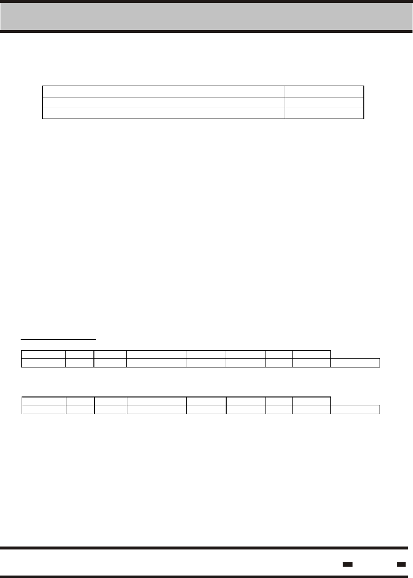
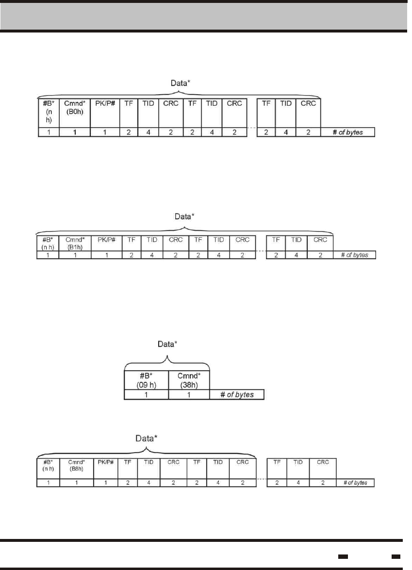
6.5.5.2.13. Read Data
Stopping all tags.
Stopping specific tags
#B*
(09 h)
Cmnd*
(39h)
1 1 # of bytes
#B*
(n h)
Cmnd*
(B9h)
PK/P# TF TID CRC TF TID CRC TF TID CRC
1 1 1 2 4 2 2 4 2 2 4 2 # of bytes
#B*
(n h)
Cmnd*
(BBh)
PK/P# TF TID CRC TF TID CRC TF TID CRC
1 1 1 2 4 2 2 4 2 2 4 2 # of bytes
Seal #1 Seal #2 Seal #j
Seal #1 Seal #2 Seal #j
#B*
(nh)
Cmnd*
(63h)
BA-Base A ddres s BL-Block Length
1 1 2 2 # of bytes
Where:
BA This is the base address in the block of data's
memory.
BL This is the data block length.
Data*
Data*
Data*
Data*
Hi-G-Tek Ltd. Microelectronics & Asset Tracking Technology 142
6 RS 485/232 Communication Protocol
#B*
(n h)
Cmnd*
(68h)
TF TID PK/P# BA
Base ad dres s
Data
1 1 2 4 1 2 m # of bytes
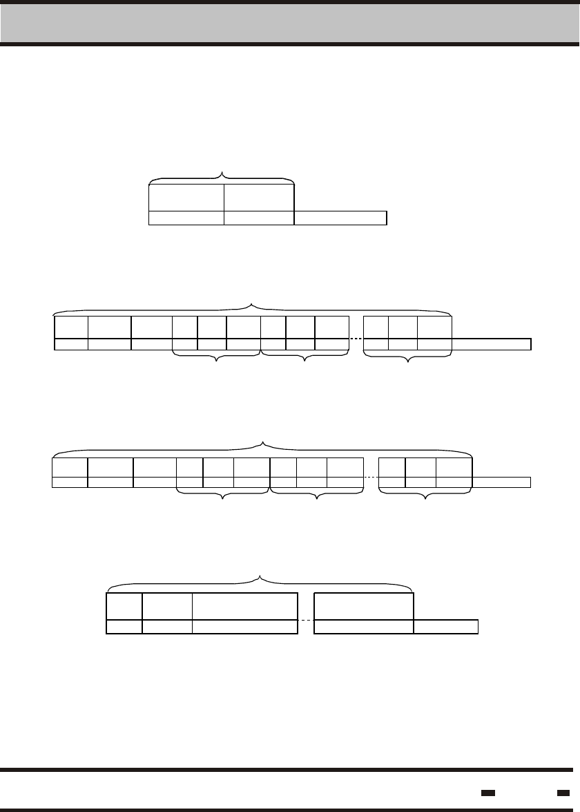
6.5.5.2.14. Write Data
6.5.5.2.15. Reset Data
PK/P# = 11h. At present the packets are fixed.
#B*
(nh)
Cmnd*
(AAh)
PK/P# TF TID CRCt TF8
TID8
CRC8
1 1 1 2 4 2 2 4 2 # of bytes
Seal #1 Seal #8
Up to 8 seals can be reset in one cycle
6.5.5.2.16. Set/Reset Status.
#B*
(17 h)
Cmnd*
(6Bh)
TF TID Bit mask Bit value
1 1 2 4 4 4 # of bytes
Only some of the flags can be set and reset.
Bit mask marks the status bits to be reset.
A value of 0 means “don't modify”.
A value of 1 is to “reset value to zero”.
Each bit corresponds to the appropriate bit in the LTS.
Data*
Data*
Data*
Hi-G-Tek Ltd. Microelectronics & Asset Tracking Technology 143
6 RS 485/232 Communication Protocol
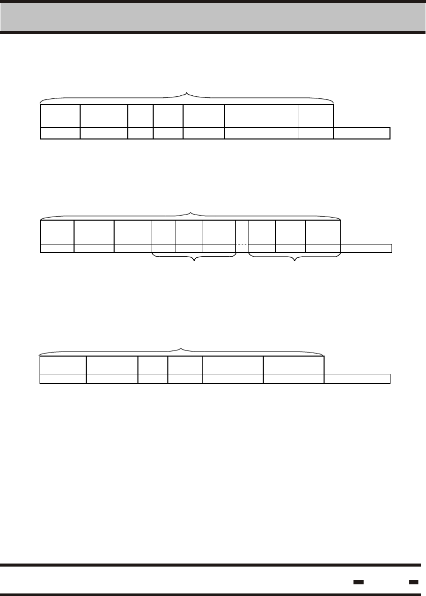
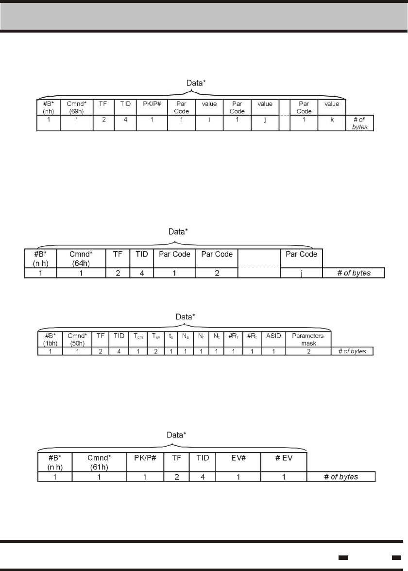
6.5.5.2.17. Write Parameters
6.5.5.2.18. Read Parameters
6.5.5.2.19. Addressed Verify
6.5.5.2.20. Read Events
TF&TID=00 is for a broadcast command.
PK/P# = 11h. At present the packets are fixed.
The following parameters are not applicable to this command:
Na, Nt, Rt.
is the sequential number of the first Event.
is the number of events to be read from the memory.
Where:
EV#
#EV
Hi-G-Tek Ltd. Microelectronics & Asset Tracking Technology 144
6 RS 485/232 Communication Protocol
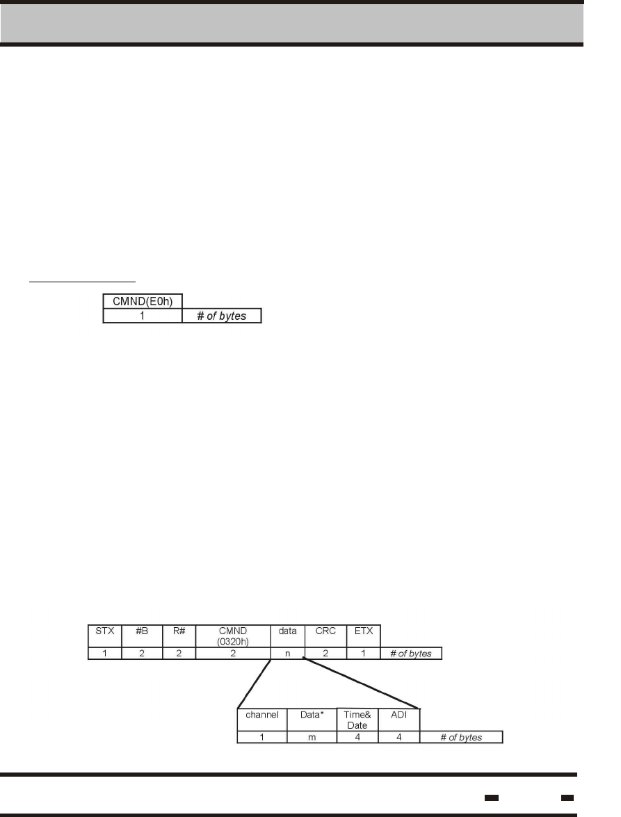
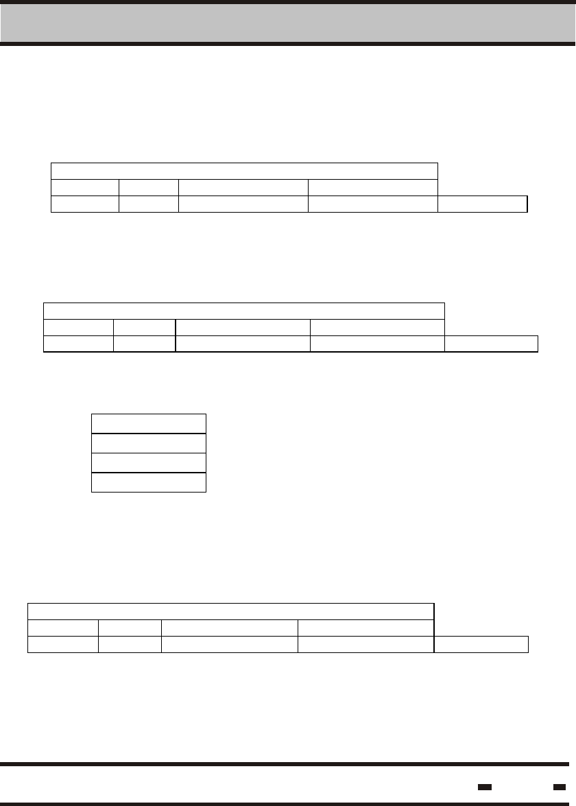
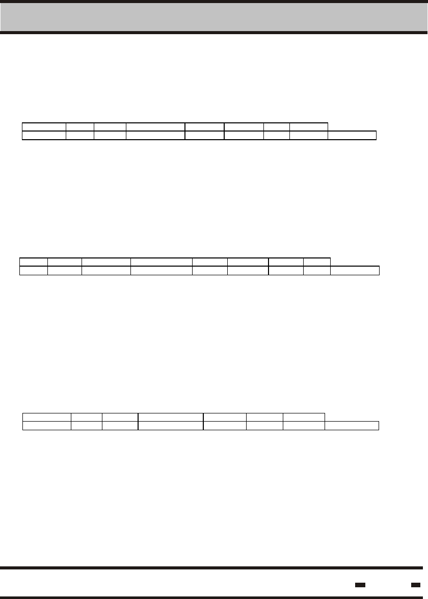
6.5.5.3. Get Results
6.5.5.3.1. Command Transmission
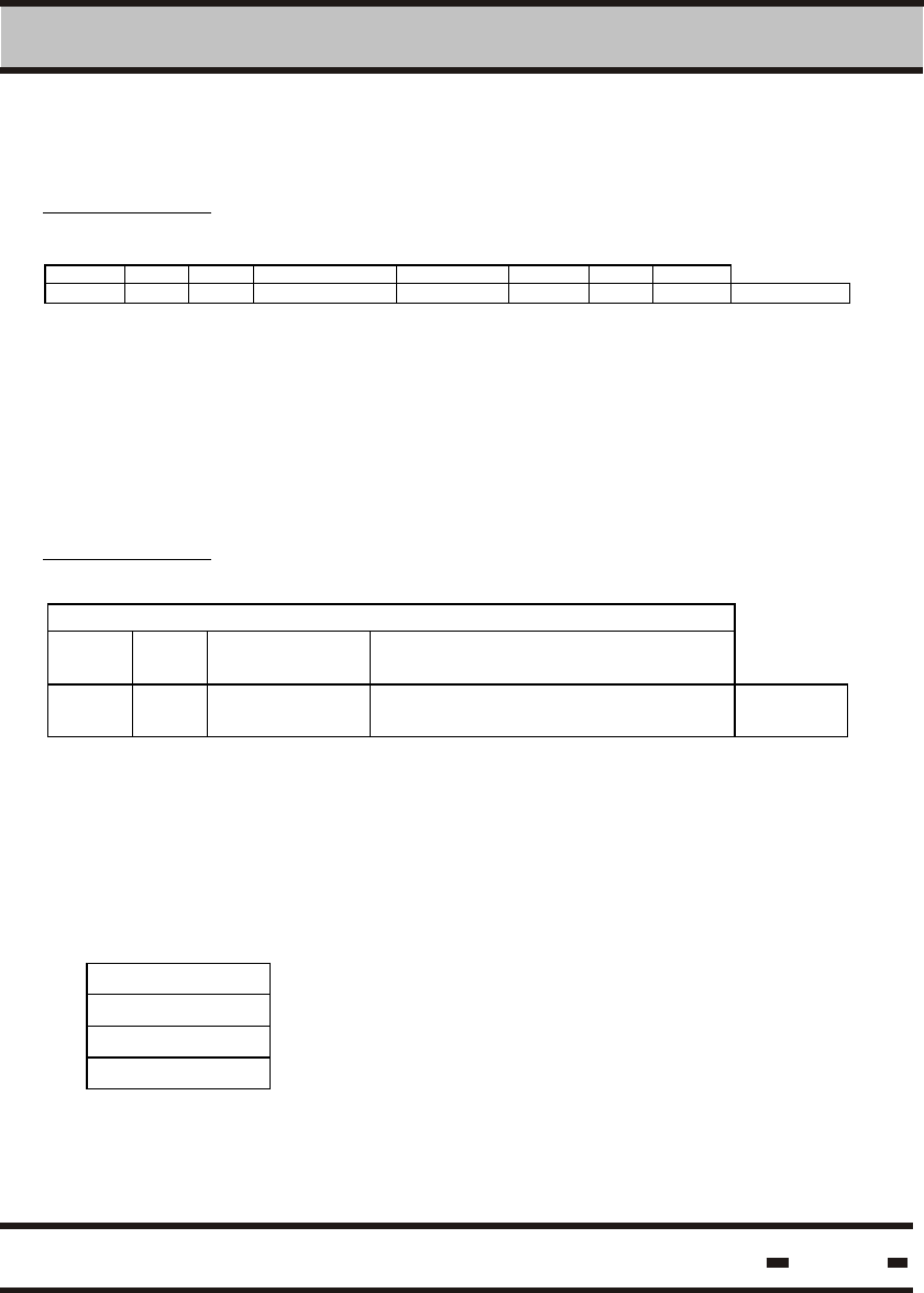
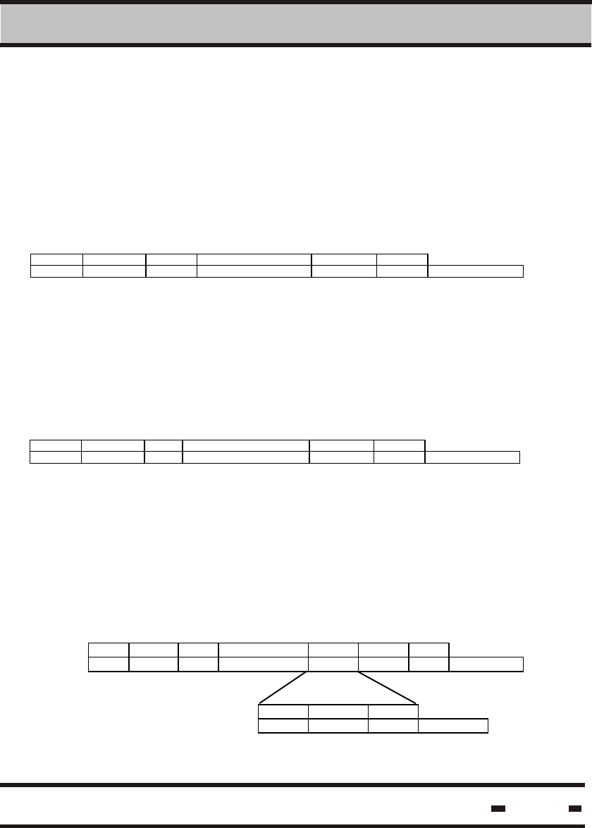
6.5.5.3.2. Get Results Command General Response
The following string is the general response
This command is used to retrieve the results after an RF
communication session.
LSC > Reader
Reader > LSC
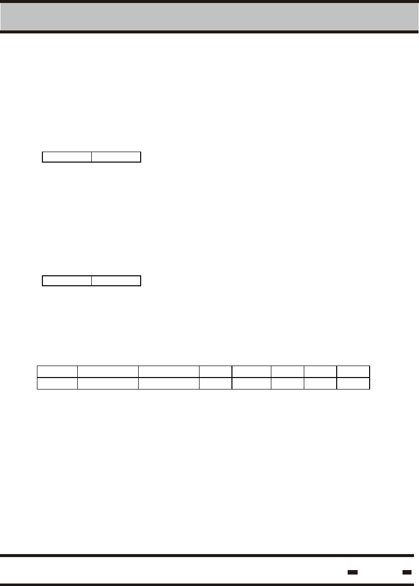
STX #B R# CMND(0015h) Channel CRC ETX
1 2 2 2 1 2 1 # of bytes
Channel indicates the source channel for the results. The value is
according to the table in paragraph 5.5.2.1.
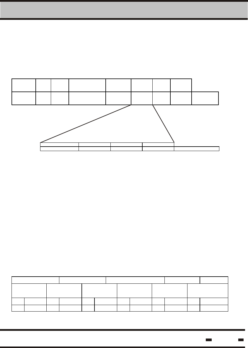
STX #B R# MSGT(xx20h) R_status DATA CRC ETX
1 2 2 2 2 n 2 1 # of bytes
channel PK P# Data*
1 1 1 m # of bytes
Where:
MSGT The high byte of MSGT is according the scenario in
use. The low byte is 20 h.
DATA In case the result is not ready, the value of this field
is 05 hex error code see paragraph 5.4. If the results
are ready, the following applies:
Hi-G-Tek Ltd. Microelectronics & Asset Tracking Technology 145
6 RS 485/232 Communication Protocol
Total number of packets.
Packet number sequence number.
This string contains the seal records. The field
should first be concentrated from all packets
before being analyzed.
Seals Records:
Data*1 Data*2 - - - - - - - - - - - - - - Data*PK-1 Data*PK
Seal
record
Seal
record
Seal
record
Seal
record
Seal
record
Seal record
#B Data** #B Data** #B Data** #B Data** #B Data** #B Data**
1 r r r r r r
Where:
Data**
TF TID Message Type Data Result
2 4 1 # of bytes
Where:
In case of a problem the Message Type's MSB will be set to “1”.
If no seal is detected:
Data*1
Seal record
#B=0
1
PK
P#
Data*
TF&TID
Message Type
is the ID of the seal.TF&TID
is the transmitted Cmnd*.
#B
Data**
is the number of bytes for a seal record (including
the #B field)
is the data received after executing the RF command
led by TF, TID and Message Type.
Hi-G-Tek Ltd. Microelectronics & Asset Tracking Technology 146
6 RS 485/232 Communication Protocol
For the case of an unfinished RF session the complete response is:
Reader > LSC
Reader > LSC
STX #B R# MSGT(xx15h) R_status error CRC ETX
1 2 2 2 2 1 2 1 # of bytes
6.5.5.3.3. Get Results Command Response for Verify Command.
The response data field is a string of data received from all the seals.
Each seal record is marked with the seal's TF&ID. The internal data
field is according to the Parameters mask transmitted with the
Verify command.
Data**
TF TID Message
Type
Data results according to the bit
mask
2 4 1 # of
bytes
is the ID of the seal.
is 10 h.
Data*1
Seal record
#B=0
1
If no seal detected:
Where:
TF&TID
Message Type
Hi-G-Tek Ltd. Microelectronics & Asset Tracking Technology 147
6 RS 485/232 Communication Protocol
6.5.5.3.4. Get Results Command Response for Tamper Command.
6.5.5.3.5. Get Results Command Response for SET Command.
Results are the same as for the Verify command.
Reader > LSC
Data**
TF TID Message Type Seal Long
Status
Seal Stamp
2 4 1 4 2 # of bytes
If no seal detected:
Data*1
Seal record
#B=0
1
6.5.5.3.6. Get Results Command Response for Suspended SET
Command.
Results are the same as for the SET command.
Results are the same as for the SET command.
6.5.5.3.7. Get Results Command Response for Soft SET Command.
6.5.5.3.8. Get Results Command Response for Read Data Command.
Reader > LSC
Data**
TF TID Message Type Short Status PK/P# Data
2 4 1 1 1 n # of bytes
PK/P# = 11h. At present the packets are fixed.
Hi-G-Tek Ltd. Microelectronics & Asset Tracking Technology 148
6 RS 485/232 Communication Protocol
6.5.5.3.9. Get Results Command Response for Write Data
Command.
Reader > LSC
Reader > LSC
Reader > LSC
Data**
TF TID Message Type Short seal status
2 4 1 1 # of bytes
6.5.5.3.10. Get Results Command Response for Deep Sleep.
Data**
TF TID Message Type Short seal status
2 4 1 1 # of bytes
If no seal detected:
Data*1
Seal record
#B=0
1
6.5.5.3.11. Get Results Command Response for Hard Wakeup
Command.
Data**
TF TID Message Type Short seal status
2 4 1 1 # of bytes
Hi-G-Tek Ltd. Microelectronics & Asset Tracking Technology 149
6 RS 485/232 Communication Protocol
6.5.5.3.12. Get Results Command Response for Reset Data
Command.
6.5.5.3.13. Get Results Command Response for Start Alert
Burst Mode Command.
6.5.5.3.14. Get Results Command Response for Stop Alert
Burst Mode Command.
Reader > LSC
Reader > LSC
Reader > LSC
Data**
TF TID Message Type Short seal status
2 4 1 1 # of bytes
For a group approach:
For a specific seal response:
Data**
TF TID Message Type Short seal status
2 4 1 1 # of bytes
Data**
Seal record
00 h
1
Data**
TF TID Message Type Short seal status
2 4 1 1 # of bytes
Hi-G-Tek Ltd. Microelectronics & Asset Tracking Technology 150
6 RS 485/232 Communication Protocol
6.5.5.3.15. Get Results Command Response for Set/Reset Status
Command.
Reader > LSC
Reader > LSC
Reader > LSC
For a group approach:
Data**
Seal record
00 h
1
For a specific seal response:
Data**
TF TID Message Type Short seal status
2 4 1 1 # of bytes
6.5.5.3.16. Get Results Command Response for Write
Parameters Command.
6.5.5.3.17. Get Results Command Response for Read
Parameters Command.
Data**
TF TID Message Type Short seal status
2 4 1 1 # of bytes
Data**
TF TID Message
Type
Short
seal
status
PK/P# Par
Code
Par
Value
Par
Code
Par
Value
2 4 1 1 1 1 1 # of
bytes
Hi-G-Tek Ltd. Microelectronics & Asset Tracking Technology 151
6 RS 485/232 Communication Protocol
6.5.5.3.18. Get Results Command Response for Addressed Verify
Command.
6.5.5.3.19. Get Results Command Response for Read Events
Command.
Reader > LSC
Data**
TF TID Message
Type
Data results according to the bit
mask
2 4 1 # of
bytes
Where:
If no seal detected:
Data*1
Seal record
#B=0
1
Data**
TF TID Message
Type
Events records
2 4 1 # of
bytes
Events Records:
PK/P# EV# Event
Record
EV# Event
Record
EV# Event Record
1 1 8 or 16 1 8 or 16 1 8 or 16
PK/P# EV# Event
Record
EV# Event
Record
EV# Event Record
1 1 8 or 16 1 8 or 16 1 8 or 16
Hi-G-Tek Ltd. Microelectronics & Asset Tracking Technology 152
6 RS 485/232 Communication Protocol
FSsm #B TF TID MT(33) EV# Event Code D&T STMP CRC EM
1 2 4 1 1 1 4 2 1 # of bytes
FSsm #B TF TID MT(33) EV# Event Code RID ** CHKSUM EM
1 2 4 1 1 1 4 2 1 # of bytes
16 bytes EVENT message format
Where:
Event Code*
**
is with the value 0x80
is with one of the following values:
Data block is a group of events. Events should not be split. If the
event is too long, it should be moved to the next block.
If no seal detected:
Data*1
Seal record
#B=0
1
8 bytes EVENT message format
FSsm #B TF TID MT(33) EV# Event
Code
D&T STMP CRC EM
1 2 4 1 1 1 4 2 1 # of bytes
Where Event Code is one of the following:
Event Event Code
Wire Tampered
Low Battery
Wire Open
Wire Closed
RTC Stopped
DB Corrupted
0x02
0x03
0x04
0x05
0x08
0x09
Event Event Code MSB LSB
SET
SOFT SET
READ
TIME Changed
0x01
0x07
0x0A
0x0B
0
0
0
Delta
0
0
0
0
Hi-G-Tek Ltd. Microelectronics & Asset Tracking Technology 153
6 RS 485/232 Communication Protocol
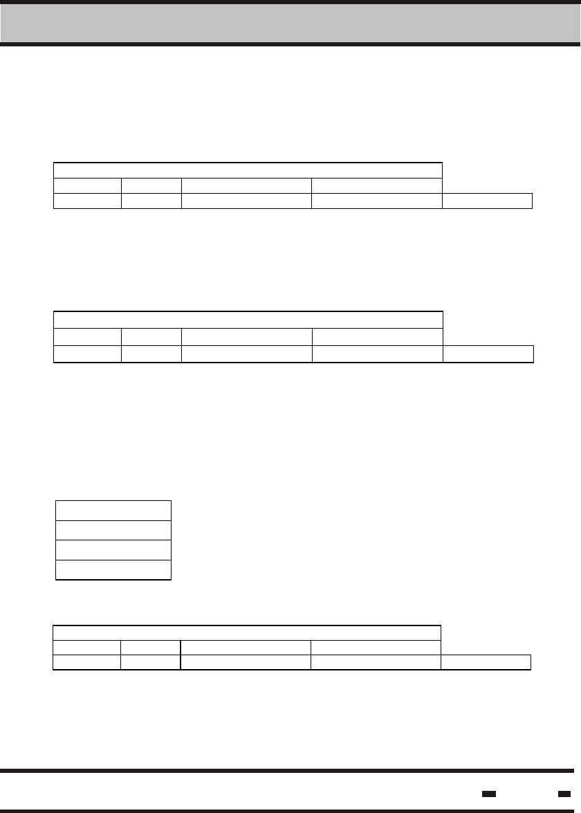
6.5.5.4. Get Status.
6.5.5.5. Get Burst Message
6.5.5.4.1. Command Transmission
6.5.5.4.2. Get Status Command Response
This command is to retrieve the READER status.
Reader > LSC
STX #B R# CMND(0016h) CRC ETX
1 2 2 2 2 1 # of bytes
The following string is the general response.
Reader > LSC
Reader > LSC
STX #B R# MSGT(xx16h) R_status CRC ETX
1 2 2 2 4 2 1 # of bytes
6.5.5.5.1. Command Transmission
This command is used to retrieve the alert messages transmitted
asynchronously by seals that are in alert burst mode.
STX #B R# CMND(0 01 Ch) Channel CRC ETX
1 2 2 2 1 2 1 # of bytes
Channel indicates the source channel for the results. The value is
according to the table in paragraph 5.5.2.1.
Hi-G-Tek Ltd. Microelectronics & Asset Tracking Technology 154
6 RS 485/232 Communication Protocol
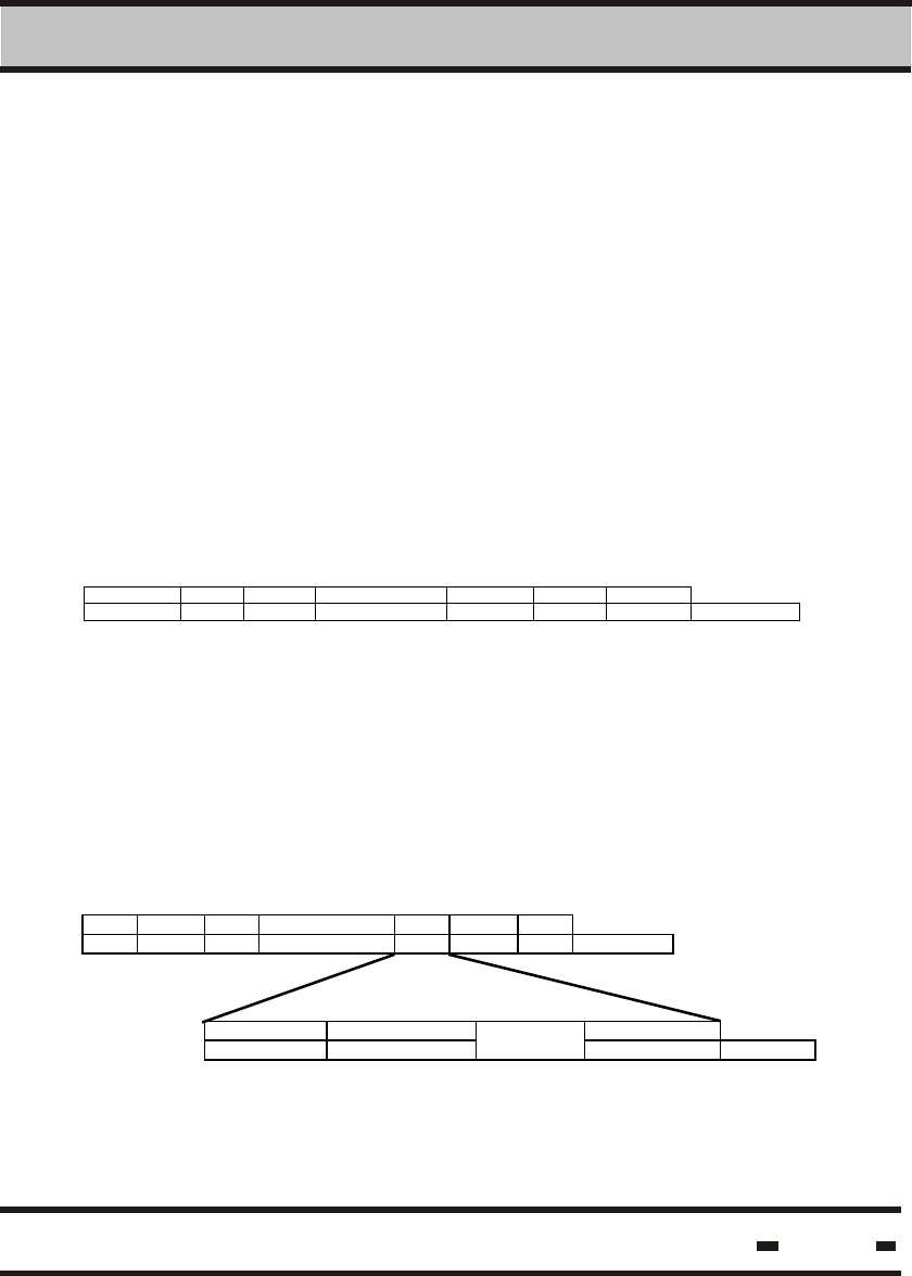
6.5.5.5.2. Get Burst Message Command General Response.
The following string is the general response.
Reader > LSC
STX #B R# MSGT(xx1Ch) R_statu
s
DA TA CRC ETX
1 2 2 2 2 n 2 1 # of
bytes
channel PK P# Data*
1 1 1 m # of bytes
Where:
high byte of MSGT is according the scenario in use.
The low byte is 1C h.
If the result is not ready, the value of this field is 05
hex error code see Paragraph 5.4. If the result is
ready the following applies:
Total number of packets.
Packet number sequence number.
This string ccontains the seal records. The field
should first be concentrated from all packets before
analyzing.
Seals Records:
Data*1 Data*2 - - - - - - - - - - - - - - Data*PK-1 Data*PK
Seal
record
Seal
record
Seal
record
Seal
record
Seal
record
Seal record
#B Data** #B Data** #B Data** #B Data** #B Data** #B Data**
1 r r r r R r
MSGT
DATA
PK
P#
Data*
Hi-G-Tek Ltd. Microelectronics & Asset Tracking Technology 155
6 RS 485/232 Communication Protocol
Data**
TF TID Message Type Data Results
2 4 1 # of bytes
If no seal detected:
Data*1
Seal record
#B=0
1
6.5.5.6. Reset Reader.
6.5.5.6.1. Command Transmission
This command performs a general reset to all readers at one time.
In this command, the LSC does not prompt.
LSC > Reader
STX #B R# CMND(0014h) CRC ETX
1 2 2 2 2 1 # of bytes
Where:
#B
DATA**
is the number of bytes for a seal record (including
the #B fiels).
is the data received after executing the RF command
led by TF, TID and Message Type
Hi-G-Tek Ltd. Microelectronics & Asset Tracking Technology 156
6 RS 485/232 Communication Protocol
6.5.5.6.2. Reset Reader Command Response
The following string is the response.
Reader > LSC
LSC > Reader
STX #B R# MSGT(xx14h) R_status CRC ETX
1 2 2 2 2 2 1 # of bytes
6.5.5.7. Write Parameters
6.5.5.7.1. Command Transmission
6.5.5.7.2. Write Parameters Command Response
This command enables modification of the parameter's value in
the reader. Not all the parameters are available for modification.
Please see Table 5.3 .
STX #B R# CMND(0006h) Data CRC ETX
1 2 2 2 n 2 1 # of bytes
PAR1code value PAR2 code value PARm code value
1 i 1 k 1 l # of bytes
The following string is the response.
Reader > LSC
STX #B R# MSGT(xx06h) R_status CRC ETX
1 2 2 2 2 2 1 # of bytes
Hi-G-Tek Ltd. Microelectronics & Asset Tracking Technology 157
6 RS 485/232 Communication Protocol
6.5.5.8. Read Parameters.
6.5.5.8.1. Command Transmission
This command enables the reading of the parameter's value from
the reader.
LSC > Reader
STX #B R# CMND(0007
h)
Data CRC ETX
1 2 2 2 n 2 1 # of bytes
PAR1code PAR2 code PARm code
1 1 1 # of bytes
6.5.5.8.2. Read Parameters Command Response
The following string is the response.
Reader > LSC
STX #B R# MSGT(xx07h) R_status Data CRC ETX
1 2 2 2 2 n 2 1 # of bytes
value value value
i k l # of bytes
Hi-G-Tek Ltd. Microelectronics & Asset Tracking Technology 158
6 RS 485/232 Communication Protocol
6.5.5.9. BIT
6.5.5.9.1. Command Transmission.
This command generates a set of built-in test procedures.
LSC > Reader
STX #B R# CMND(0009h) CRC ETX
1 2 2 2 2 1 # of bytes
6.5.5.9.2. BIT Command Response.
The following string is the response.
Reader > LSC
STX #B R# MSGT(xx09 h) R_status CRC ETX
1 2 2 2 4 2 1 # of bytes
6.5.5.10. Sleep.
6.5.5.10.1. Command Transmission
This command places the Reader in sleep mode of operation to
save energy. The Wakeup command wakes the Reader from this
mode.
LSC > Reader
STX #B R# CMND(0008h) CRC ETX
1 2 2 2 2 1 # of bytes
6.5.5.10.2. Sleep Command Response.
The following string is the response:
Reader > LSC
STX #B R# MSGT(xx08h) R_status CRC ETX
1 2 2 2 2 2 1 # of bytes
Hi-G-Tek Ltd. Microelectronics & Asset Tracking Technology 159
6 RS 485/232 Communication Protocol
6.5.5.11. Unsynchronized Reader Message.
6.5.5.11.1. Message Transmission
When in unsynchronized mode of operation the Reader may burst
with a message. The following string will be received for each seal.
Reader > LSC
STX #B R# MSGT(800Ah) R_status Data CRC ETX
1 2 2 2 2 n 2 1 # of bytes
Channel #B TF TID Command code Short status ORG_ID
1 1 2 4 1 1 3 # of bytes
ORG_ID is an option in the response. It depends on the seal's
configuration.
6.5.5.11.2. Message Command Ack.
The following string is the response:
LSC > Reader
STX #B R# CMND(000Ah) CRC ETX
1 2 2 2 2 1 # of bytes
Hi-G-Tek Ltd. Microelectronics & Asset Tracking Technology 160
6 RS 485/232 Communication Protocol
6.5.5.12. Get Reader's Baud Rate.
6.5.5.12.1. Command Transmision
This command places the Reader in a sleep mode of operation
to save energy. The Reader will wakeup from this mode by
receiving a Wakeup command.
LSC > Reader
STX #B R# (0000) CMND (0 0f f h) R_ID CRC ETX
1 2 2 2 4 2 1 # of bytes
6.5.5.12.2. Get Reader's Baudrate Response.
The following string is the response:
Reader > LSC
STX #B R# MSGT(80ff h) R_ID baudrate CRC ETX
1 2 2 2 4 4 2 1 # of bytes
Baudrate: 2400, 4800, 9600, 19200, 38400
6.5.5.13 Set Reader's Baud Rate.
6.5.5.13.1. Command Transmission
This command puts the Reader in a sleep mode of operation to
save energy. The Wakeup command wakes the Reader from this
mode. The baudrate is updated after the completion of this
command and receipt of the response.
LSC > Reader
STX #B R# (0000) CMND (00fe h) R_ID baudrate CRC ETX
1 2 2 2 4 4 2 1 # of bytes
The baud rate is interpreted as a decimal number translated
into a 32 bit binary number or vise-versa.
Hi-G-Tek Ltd. Microelectronics & Asset Tracking Technology 161
6 RS 485/232 Communication Protocol
6.5.5.13.2. Set Reader's Baud Rate Response.
6.5.5.14. Set Reader's Address
6.5.5.14.1. Command Transmission
6.5.5.14.2. Set Reader's Address Response.
The following string is the response:
Reader > LSC
STX #B R# MSGT(80feh) R_ID baudrate CRC ETX
1 2 2 2 4 4 2 1 # of bytes
This command sets the Reader's address for RS-485 communication
purposes.
LSC > Reader
STX #B R#(0000) CMND(0012h) R_ID New add CRC ETX
1 2 2 2 4 2 2 1 # of bytes
The following string is the response for a command transmission to
a specific Reader.
Reader > LSC
STX #B R# MSGT(xx12h) R_status CRC ETX
1 2 2 2 2 2 1 # of bytes
The R# is with the new address.
* To modify an old address, the above command can be used with
a specific Reader by specifying R# with the old address.
If the above command is a broadcast, there will be no response.
Hi-G-Tek Ltd. Microelectronics & Asset Tracking Technology 162
6 RS 485/232 Communication Protocol
6.5.5.15 Acknowledge OK.
LSC > Reader
LSC > Reader
LSC > Reader
LSC > Reader
This string is a one-way string that acknowledges a positive message
received from the READER.
STX #B R# CMND(0092h) CRC ETX
1 2 2 2 2 1 # of bytes
6.5.5.16. Acknowledge Failed.
6.5.5.17. Save Command
6.5.5.17.1. Command Transmission
This string is a one-way string that acknowledges a message
indicating a problem coming from the READER.
STX #B R# CMND (0094h) CRC ETX
1 2 2 2 2 1 # of bytes
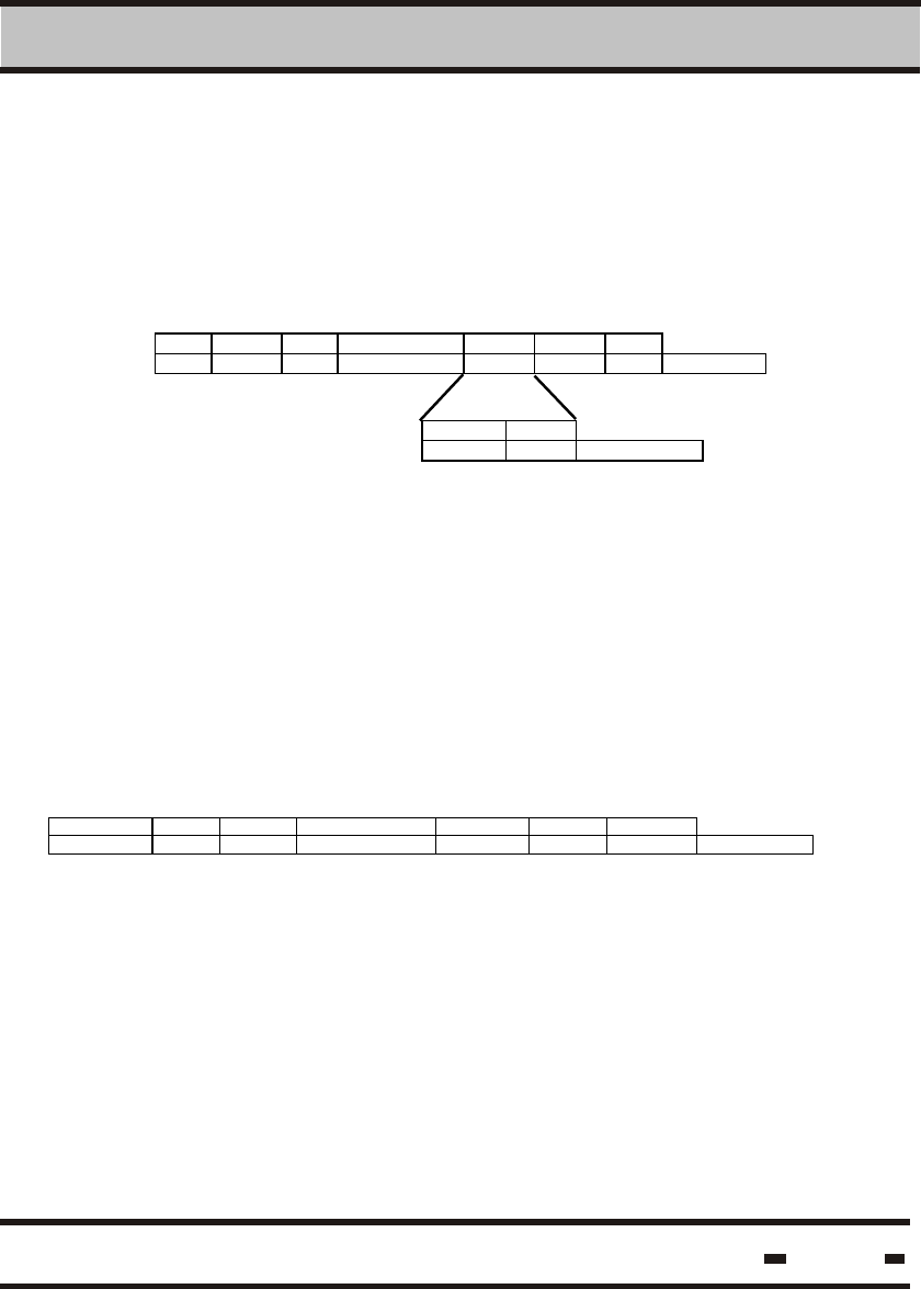
This command sends a command to the Reader for later execution
by using the “Execute Saved Command”.
LSC > Reader
STX #B R# CMND(000Fh) data CRC ETX
1 2 2 2 2 1 # of bytes
phase CMND* Data*
1 2 # of bytes
Hi-G-Tek Ltd. Microelectronics & Asset Tracking Technology 163
6 RS 485/232 Communication Protocol
Where:
Phase is the duration from the end of the “Execute Saved
Command” and the time required to execute the
saved command. The phase is in units of 1.024 msec.
CMND* is the command code of the saved command for
delayed execution.
Data* is the relevant data field for the CMND*
If data=0 this command will clear the saved command.
6.5.5.17.2. Save Command Response.
The following string is the response:
Reader > LSC
STX #B R# MSGT(XX0Fh) R_status CRC ETX
1 2 2 2 2 2 1 # of bytes
6.5.5.18. Execute Saved Command
6.5.5.18.1. Command Transmission
This command executes the saved command.
This is a broadcast command sent to all readers.
There will be no response from any reader to this command.
LSC > Reader
STX #B R# CMND(00017h) data CRC ETX
1 2 2 2 4*k 2 1 # of bytes
Reader I D [1] Reader I D [2] Reader I D [k]
4 4
. . . . . . . . . .
4 # of bytes
The data field details the readers by their IDs.
Hi-G-Tek Ltd. Microelectronics & Asset Tracking Technology 164
6 RS 485/232 Communication Protocol
6.5.5.18.2. Execute Saved Command Response
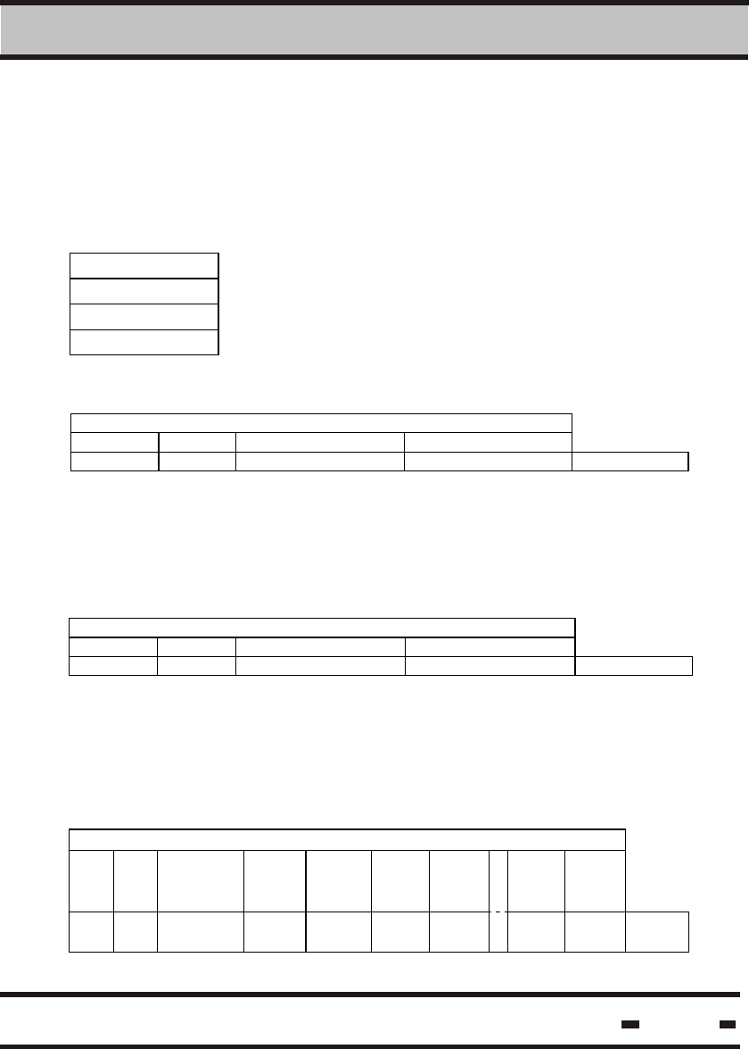
6.5.5.19. Read Channel Definitions Command
6.5.5.19.1. Command Transmission
6.5.5.19.2. Read Channel Definitions Response.
There is no response for this command.
This command allows the reading of the definitions for a device.
LSC > Reader
STX #B R# CMND(0011h) channel CRC ETX
1 2 2 2 1 2 1 # of bytes
is the channel number that the device is connected to.
Channel can be 0 to indicate the MCU, or 1,2 etc for
the other channels.
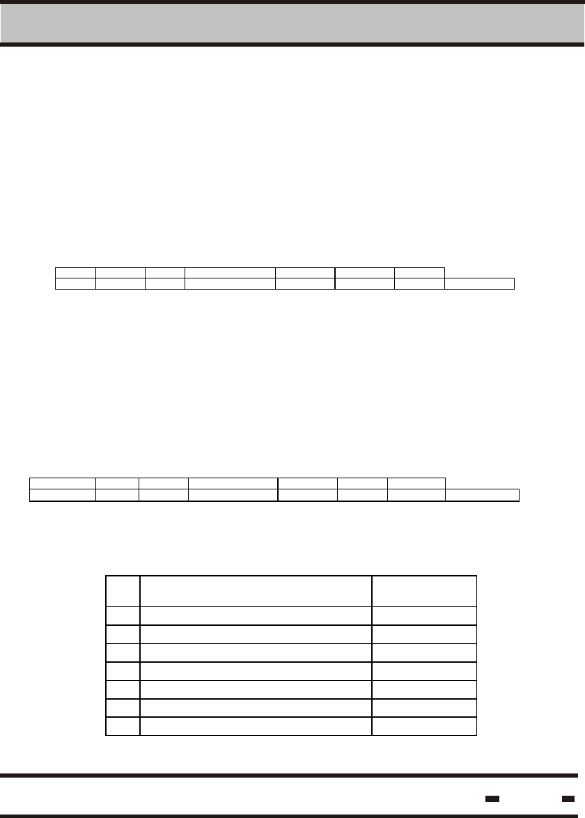
The following string is the response:
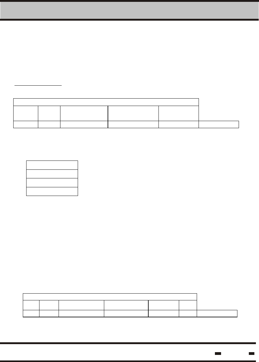
Reader > LSC
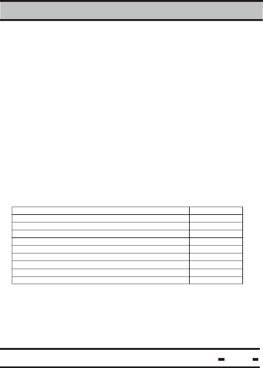
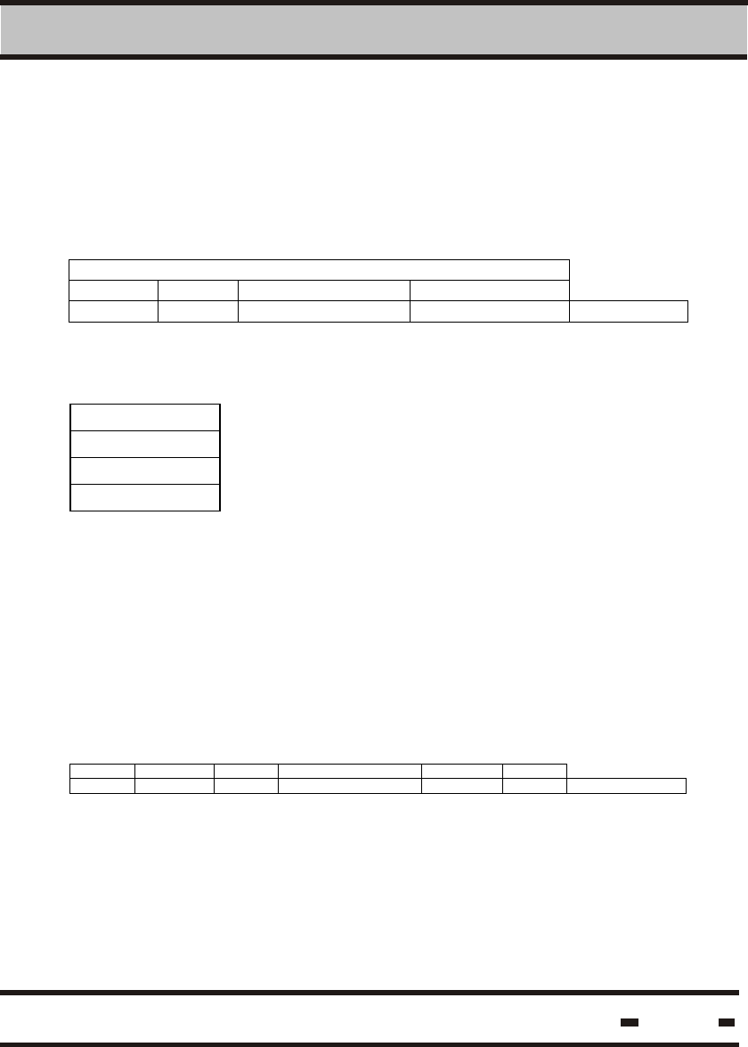
STX #B R# MSGT(XX11h) file CRC ETX
1 2 2 2 82 2 1 # of bytes
Where:
File is the data file that defines the device.
File structure is:
Name Size
[bytes]
1 Part number 16
2 Serial number 16
3 Hardware Version 4
4 Production date 10
5 Production Batch number 4
5 Description 32
6 Reserved 45
The format is ASCII
Channel
Where:
Hi-G-Tek Ltd. Microelectronics & Asset Tracking Technology 165
6 RS 485/232 Communication Protocol
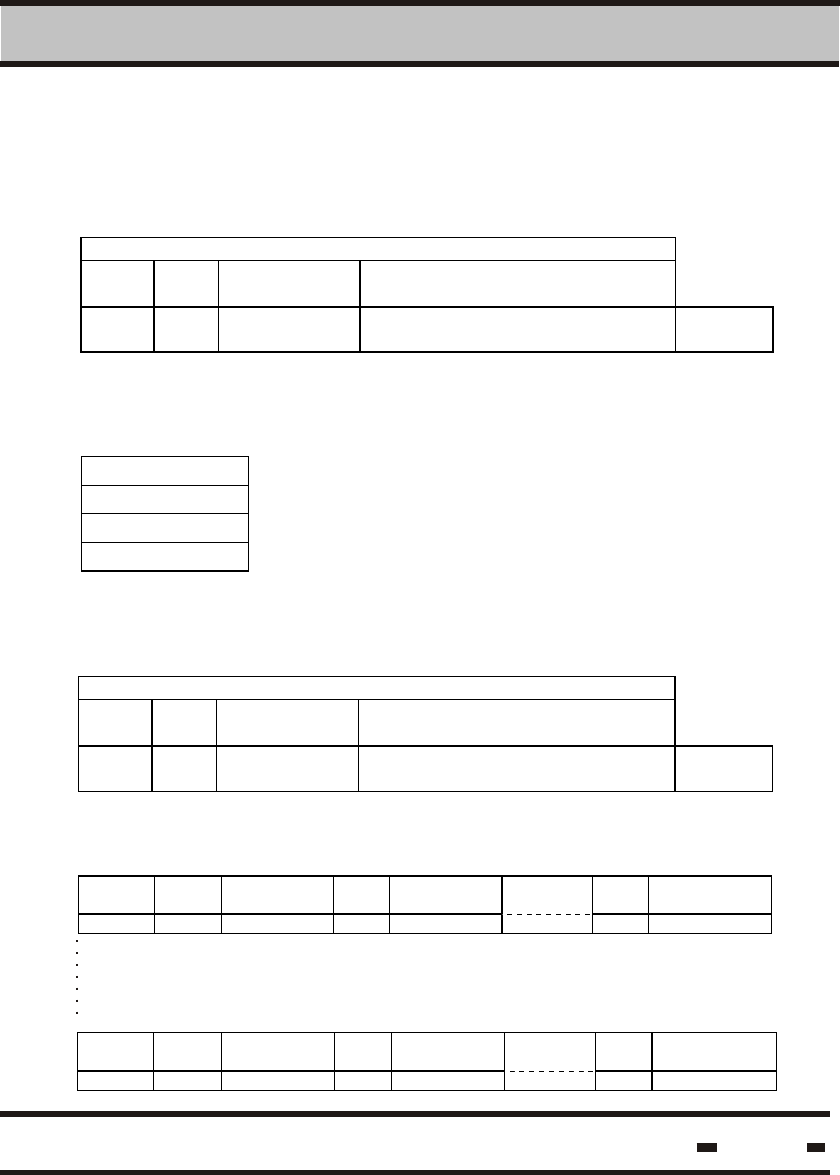
6.5.5.20. Write Channel Definitions Command
6.5.5.20.1. Command Transmission
6.5.5.20.2. Write Channel Definition Response
This command enables the writing of definitions of a device.
LSC > Reader
STX #B R# CMND(0010h) data CRC ETX
1 2 2 2 2 1 # of bytes
channel file
1 82 # of bytes
Where:
Channel is the channel number that the device is connected to.
Channel can be 0 to indicate the MCU, or 1,2 etc
for the other channels.
File is the data file that defines the device.
The following string is the response:
Reader > LSC
STX #B R# MSGT(XX10h) R_status CRC ETX
1 2 2 2 2 2 1 # of bytes

Hi-G-Tek Ltd. Microelectronics & Asset Tracking Technology 166
6 RS 485/232 Communication Protocol