Contents
Users Manual Part 2

The
System
Chapter 5
Hi-G-Tek Ltd. Microelectronics & Asset Tracking Technology 50
System
5
5.1.System description
T
Complete Reader Session
Reader
H
Ine
at
e
d
r
e
rorgation
Random
Access
Window
Alert
Window
Tcw Taw
Trw
Thw
Tiw
Readers
Interlace
Window
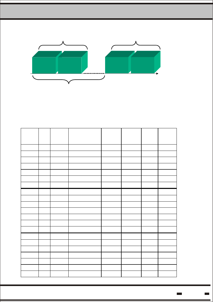
5.1.1. General.
Hi-G-Tek DataSeals operate in sleep mode to conserve power. A
pre-determined periodically awakens them from sleep mode. This
allows them to monitor the surrounding airwaves for a Reader's
wake up signal.
Tw is the notation used throughout this manual for the wakeup cycle
time of the seal.
When the Reader initiates a session, it transmits a stream of data bits
of programmable length. The notation of the data stream length is Thw.
The seals use the SLOTTED ALOHA concept to communicate back to
a Reader. The length of an ALOHA time slot is notated as Ts. (Ts is
also notated as a window). This time slot is usually of fixed duration.
For the Verify, Addressed Verify and Tamper commands, Ts should
be defined externally in the command (see paragraph 5.6.3.2.).
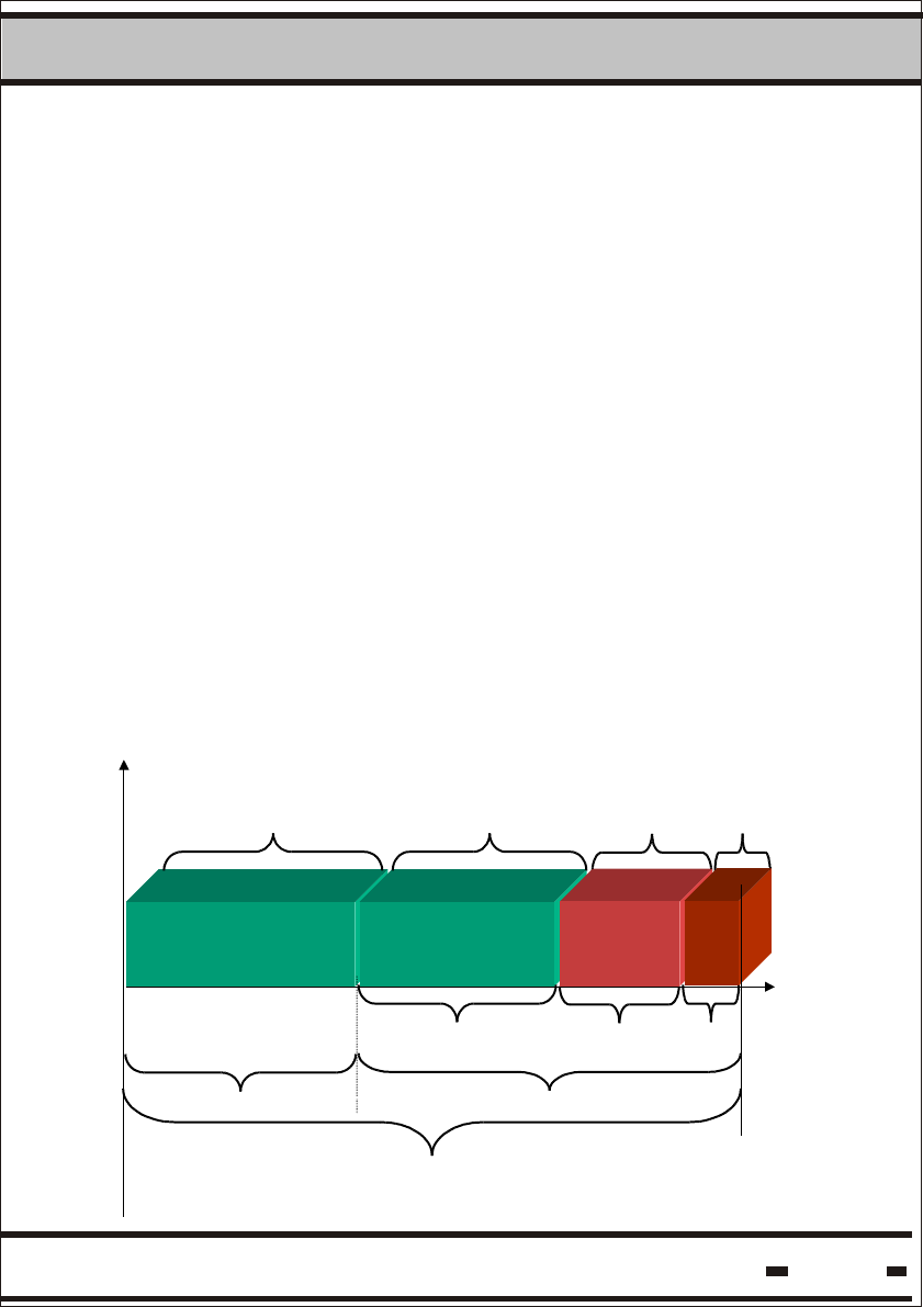
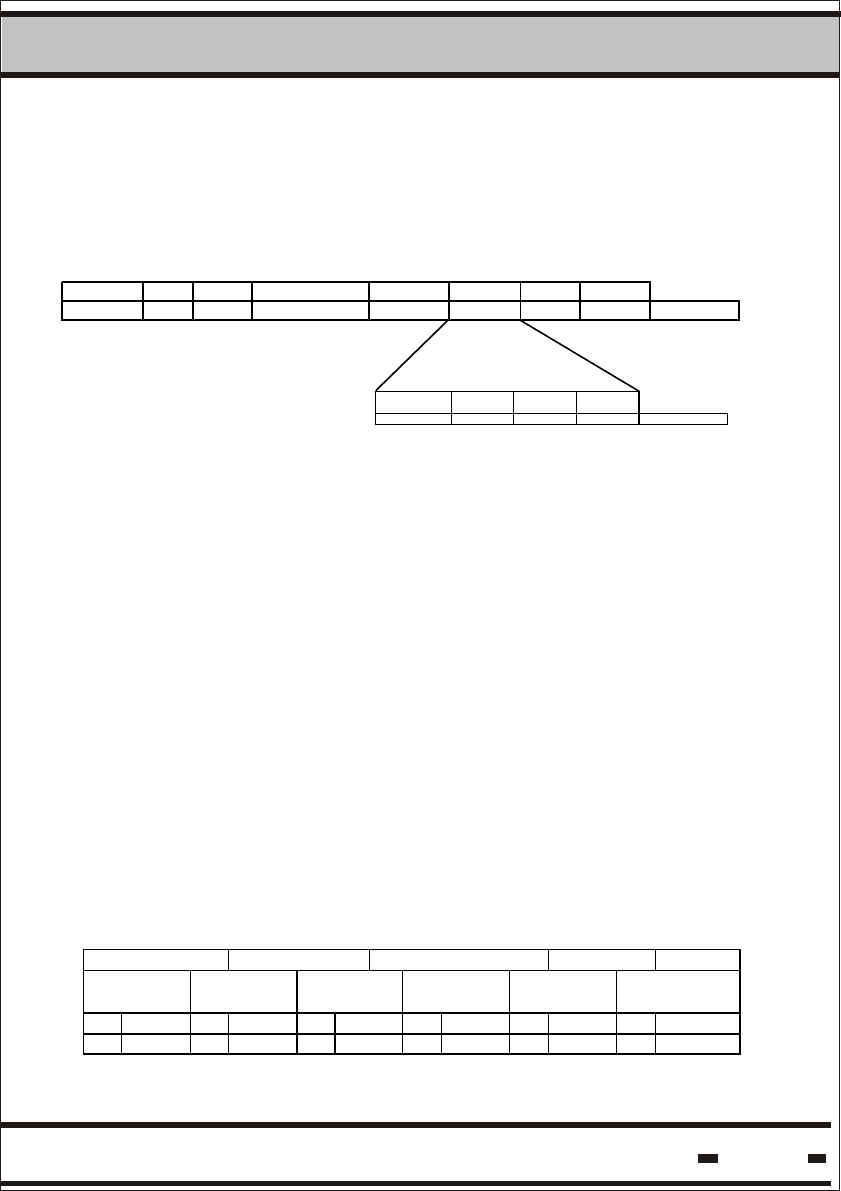
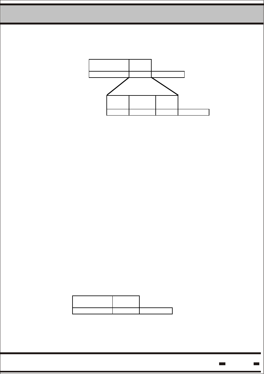
Fig. 5.1 - RF Communication Channels
Hi-G-Tek Ltd. Microelectronics & Asset Tracking Technology 51
5System
Ts can have one of the following values: 21, 41, 63, 81 msec.
The System has four communication channels
Reader Interrogation Header with time duration of Thw. Within
this time frame the Reader sends a data stream to the seals.
Readers Interlace Window with time duration of Tiw. This
window is to allow other Readers to transmit and to share one
Random Access Window.
Random Access Window with time duration of Tcw. During this
period seals responds in random access mode. Because the
access is random, collisions between seal messages are to be
expected.
Alert Window with time duration of Taw. The last channel is an
emergency channel allowing seals with high priority alert messages
to transmit the message to the Reader.
Trw is the notation used for the seals transmitting (Reader is receiving)
time frame.
A complete communication Reader Session is Thw + Trw.
To overcome collisions, the seals should retransmit their message
several times within the Random Access Window. The number of
retransmissions should be defined externally in the command and is
called Rr.
The seal may also retransmit in the Alert Window. This is notated as Rt.
Both Thw and Tw can be programmed.
The relationship between Thw and Tw should be kept constant.
Thw=Tw+ 135 msec
See paragraph 5.2.3. for information on how to calculate Thw
and Tw

Hi-G-Tek Ltd. Microelectronics & Asset Tracking Technology 52
5System
Table 5.1 Number of retries within the Random Access Window
When there are a certain number of seals in the Reader's receiving
zone, probability calculations show that more than one Seal
Transmission is required to obtain a complete result.
The following table demonstrates the number of retransmissions
required for different situations.
# Of seal slots (Ts)
Max
# of
Seals
Min #
of
Reader
Sessions 30 40 50 60 70 80 90 100 110 120 130 140 150 160 170 180 190 200 210 220 230 240 250
1 4 3 3 3 3 3 3 3 3 3 3 3 3 3 3 3 2 2 2 2 2 2 2
2
2 2 2 2 2 2 2 2 1 1 1 1 1 1 1 1 1 1 1 1 1 1 1 1
1 - 9 6 5 5 4 4 4 4 4 4 4 4 3 3 3 3 3 3 3 3 3 3
3
2 3 3 2 2 2 2 2 2 2 2 2 2 2 2 2 2 2 2 2 2 2 2 2
1 - - - - 10 6 6 6 5 5 5 4 4 4 4 4 4 4 4 4 4 4 4
4
2 - 4 3 3 2 2 2 2 2 2 2 2 2 2 2 2 2 2 2 2 2 2 2
1 - - - - - - - 8 7 7 6 6 6 6 5 5 5 5 5 4 4 4 4
5
2 - - 5 4 3 3 3 3 2 2 2 2 2 2 2 2 2 2 2 2 2 2 2
1 - - - - - - - - - 10 8 8 8 6 6 6 6 6 5 5 5 5 5
6
2 - - - 5 4 3 3 3 3 3 3 2 2 2 2 2 2 2 2 2 2 2 2
1 - - - - - - - - - - - - 9 8 8 7 6 6 6 6 6 6 5
7
2 - - - - 6 5 4 4 3 3 3 3 3 3 2 2 2 2 2 2 2 2 2
1 - - - - - - - - - - - - - - - 10 8 8 7 7 6 6 6
8
2 - - - - - - 5 5 4 3 3 3 3 3 3 3 3 3 3 2 2 2 2
1 - - - - - - - - - - - - - - - - - - 9 9 9 8 8
9
2 - - - - - - - 6 5 4 4 4 3 3 3 3 3 3 3 3 3 3 3
1 - - - - - - - - - - - - - - - - - - - - 10 9 9
10
2 - - - - - - - - 7 5 5 5 4 4 4 4 3 3 3 3 3 3 3
2 - - - - - - - - - - 7 6 5 5 4 4 4 4 4 3 3 3 3
12
3 - - - - - - 4 4 3 3 3 2 2 2 2 2 2 2 2 2 2 2 2
2 - - - - - - - - - - - - - 9 7 5 5 4 4 4 4 4 4
14
3 - - - - - - - - 5 4 3 3 3 3 3 2 2 2 2 2 2 2 2
2 - - - - - - - - - - - - - - - - 6 5 5 5 4 4 4
16
3 - - - - - - - - - - 4 4 3 3 3 3 3 3 3 2 2 2 2
2 - - - - - - - - - - - - - - - - - - - 9 7 6 5
18
3 - - - - - - - - - - - 6 4 4 4 3 3 3 3 3 3 2 2
2 - - - - - - - - - - - - - - - - - - - - - 7 6
20
3 - - - - - - - - - - - - - 5 4 4 4 3 3 3 3 3 2
3 - - - - - - - - - - - - - - - - - 5 4 3 3 3 3
25
4 - - - - - - - - - - - - - 4 3 3 3 2 2 2 2 2 2
3 - - - - - - - - - - - - - - - - - - - - - - 5
30
4 - - - - - - - - - - - - - - - - 4 3 3 3 3 3 2
4 - - - - - - - - - - - - - - - - - - - - 4 3 3
35
5 - - - - - - - - - - - - - - - - 3 3 2 2 2 2 2

Hi-G-Tek Ltd. Microelectronics & Asset Tracking Technology 53
5System
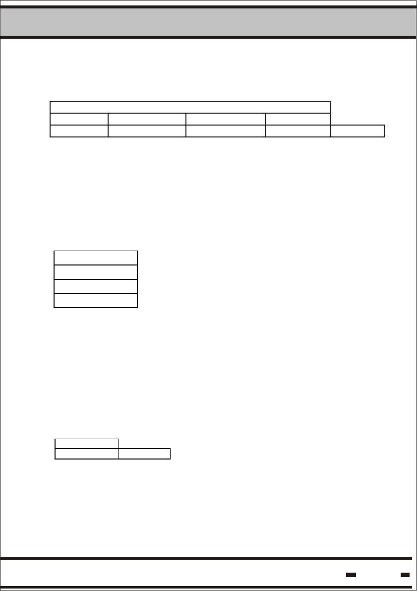
Table 5.2. Minimum Requirements
Maximum #
Seals
Minimum #
Sessions
Minimum #
Windows
Optimum #
Retries
2 1 16 6
3 1 40 9
4 1 67 10
5 1 94 9
6 1 122 9
7 1 147 10
8 1 175 9
9 1 207 8
10 1 229 10
11 2 118 8
12 2 129 7
13 2 141 9
14 2 154 9
15 2 169 9
16 2 182 9
17 2 197 9
18 2 211 7
19 2 221 8
20 2 239 8
22 2 255 9
24 3 193 5
26 3 217 6
28 3 226 6
30 3 243 6
35 4 228 4
Hi-G-Tek Ltd. Microelectronics & Asset Tracking Technology 54
5System
Table 5.3. below shows some examples of the Verify command using
different retransmissions and Reader Sessions. In this example,
Thw=3 sec; Ts=21 msec; Taw=105 msec.
Table 5.3.
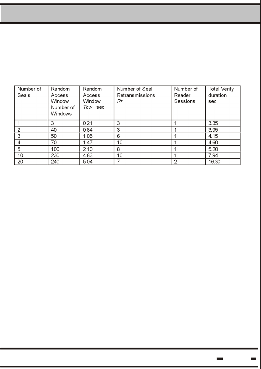
Reducing the Reader Interrogation Header - Thw increases the
speed of the Verify session. Increasing the speed of the process is
in conflict with the battery lifetime of the seal. (Higher speed = lower
battery lifetime). When designing an application, careful attention
should be paid to optimizing the correct tradeoffs between system
response time, battery lifetime and number of seals.
Taw is calculated for 5 slots of Ts.
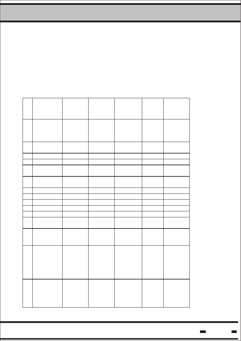
Table 5.4 demonstrates the impact of Thw on response time and
battery life. The scenario for the results in the table is a GATE
concept, whereby a seal is exposed to a reader for 6 minutes per
24 hours and: Ts=21 msec; Taw=105 msec.
Hi-G-Tek Ltd. Microelectronics & Asset Tracking Technology 55
5System
Table 5.4.
Number
of
Seals
Thw Reader
Session
time
sec
Number of
Retransmis-
sions
Rr
Number
of
Reader
Sessions
Battery
Life
Years
Total
Verify
duration
Sec
1 0.5 0.67 2 1 2.2 0.67
2 0.5 1.45 3 1 2.2 1.45
3 0.5 1.70 6 1 2.1 1.70
4 0.5 2.10 6 1 2.1 2.10
5 0.5 2.70 8 1 2.1 2.70
10 0.5 5.50 10 1 2.2 5.50
20 0.5 5.64 7 2 2.3 11.3
1 1 1.17 2 1 3.8 1.17
2 1 1.95 3 1 3.8 1.95
3 1 2.20 6 1 3.6 2.20
4 1 2.60 6 1 3.7 2.60
5 1 3.20 8 1 3.6 3.20
10 1 6.00 10 1 3.8 6.00
20 1 6.15 7 2 3.9 12.3
1 3 3.20 2 1 5.0 3.20
2 3 3.95 3 1 5.0 3.95
3 3 4.16 6 1 5.0 4.16
4 3 4.68 6 1 5.0 4.68
5 3 5.20 8 1 5.0 5.20
10 3 7.94 10 1 5.0 7.94
20 3 8.15 7 2 5.0 16.3
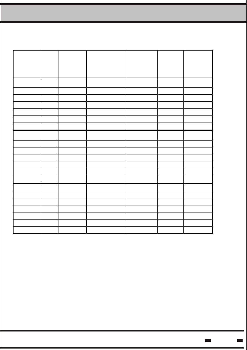
Table 5.5. demonstrates the impact of Thw on response time and
battery life for a YARD Management concept, where a seal is
constantly exposed to a reader 24 hours a day.
As mentioned previously, the reader in some cases should carry out
a number of Reader Sessions to achieve the required performance.
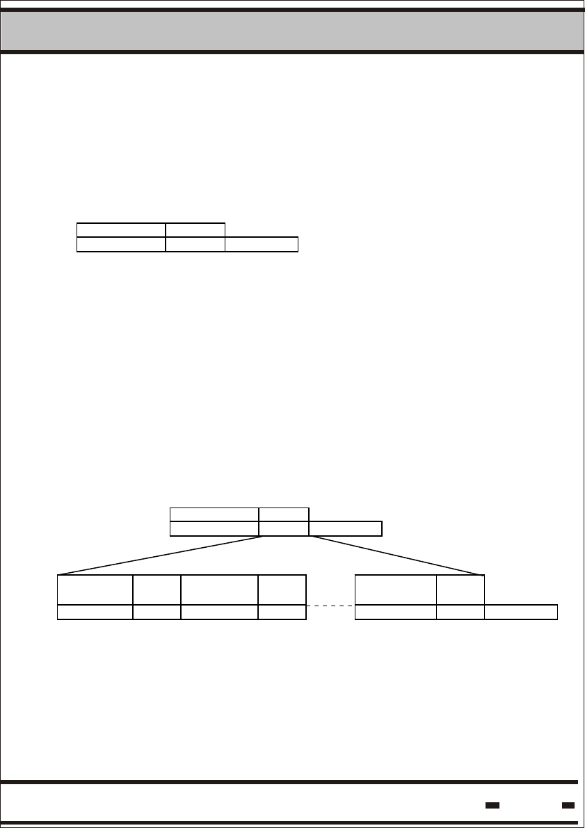
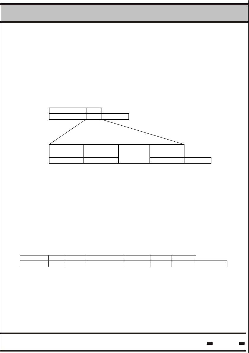
A group of Reader Sessions is a System Session. The frequency
in which the system performs System Sessions is a System Cycle
Hi-G-Tek Ltd. Microelectronics & Asset Tracking Technology 56
5System
Reader
Session 1
System Cycle
System Session
Reader
Session 2
Reader
Session 1
Reader
Session 2
System Session
The following table uses: System Cycle = 15 min; Ts=21 msec;
Taw=105 msec
Table 5.5
Number
of
Seals
Thw Reader
Session
time
sec
Number of
Retransmissions
Rr
Number
of
Windows
Number
of
Reader
Sessions
Battery
Life
Years
Total
Verify
duration
sec
1 1 1.15 2 2 1 3.78 1.15
2 1 1.95 3 40 1 3.63 1.95
3 1 2.16 6 50 1 3.23 2.16
4 1 2.79 6 80 1 3.23 2.79
5 1 3.21 8 100 1 3.0 3.21
10 1 5.94 10 230 1 2.82 5.94
20 1 6.15 7 240 2 2.47 12.29
1 2 2.15 2 2 1 5.0 2.15
2 2 2.95 3 40 1 5.0 2.95
3 2 3.16 6 50 1 4.54 3.16
4 2 3.79 6 80 1 4.54 3.79
5 2 4.21 8 100 1 4.11 4.21
10 2 6.94 10 230 1 3.77 6.94
20 2 7.15 7 240 2 3.16 14.29
1 3 3.15 2 2 1 5.0 3.15
2 3 3.95 3 40 1 5.0 3.95
3 3 4.16 6 50 1 5.0 4.16
4 3 4.79 6 80 1 5.0 4.79
5 3 5.21 8 100 1 4.7 5.21
10 3 7.94 10 230 1 4.24 7.94
20 3 8.15 7 240 2 3.48 16.29
Hi-G-Tek Ltd. Microelectronics & Asset Tracking Technology 57
5System
5.2. System Parameters.
5.2.1. Seal Parameters.
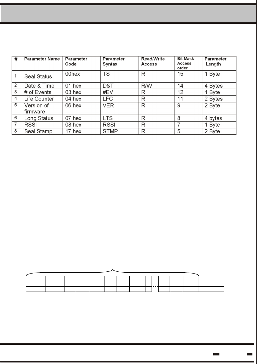
Table 5.6. describes the seal parameters. These parameters are
accessible via either the Low Frequency or the High Frequency
channels using the READ and WRITE PARAMETERS commands.
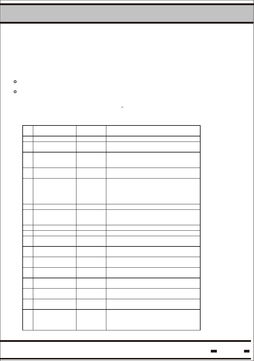
Table 5.6: Seal Parameters
# Parameter
Name
Parameter
Code
Parameter
Syntax
Read/Write
Access
Verify
command
bit
Access
order
Parameter
Length
1 Tag/Seal
Status
(Short
Status)
00hex TS R 15* 1 Byte
2 Date &
Time
01 hex D&T R 14* 5 Bytes
3 Seal Stamp 17 hex STMP R 5* 2 Bytes
4 # of Events 03 hex #EV R 12* 1 Byte
5 Version of
firmware
06 hex VER R 9* 2 Byte
6 Long
Status
07 hex LTS R 8 4 Bytes
7 Tw 31 hex TW R/W n.a 2 Bytes
8 Tp 32 hex Tp R/W n.a 2 bytes
9 ADI 13 hex ADI R/W n.a 4 Bytes
10 Department 16 hex DEP R/W 6 1 Byte
11 Tbrs 34 hex Tbrs R/W n.a 2 Bytes
12 User Data
Size
42 hex UDS R n.a 2 Bytes
13 Alert Bursts
Counter -
Cbrs.
76 hex Cbrs R/W n.a 1 Byte
14 Alert
Repetition
Rate for
Deep
Sleep
mode -Tds
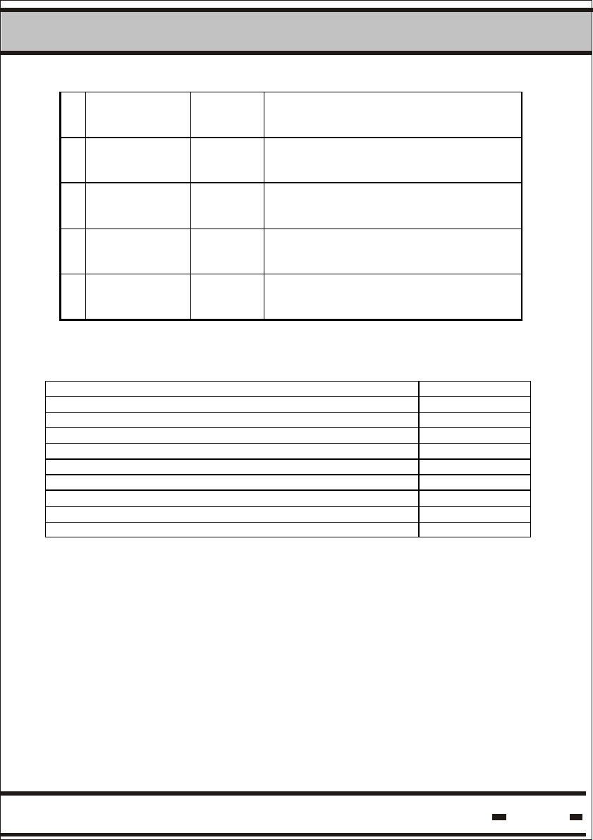
77 hex Tds R/W n.a 1 Byte
15 Alert Bursts
Counter for
Deep
Sleep
mode - Cds
78 hex Cds R/W n.a 1 Byte
* The above parameters are visible for Global=1 (See paragraph 5.8.3)
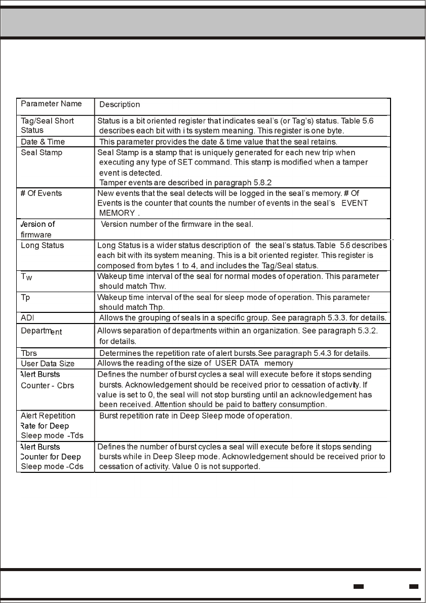
Table 5.7
Version of
Alert Bursts
Rate for Deep
Alert Bursts
Counter for Deep
5System
Hi-G-Tek Ltd. Microelectronics & Asset Tracking Technology 58

Hi-G-Tek Ltd. Microelectronics & Asset Tracking Technology 59
5System
Table 5.8a - Short Status
Bit # Status Note
7 SET/TAMP
(1)(2)
This bit is set to 1 by the SET command and
reset to 0 when a tamper event is detected.
S/T
6 LB warning
(2)
When low voltage battery is detected this bit
is set to 1. This is a warning. There is
enough time to replace the seal.
LBW
5 Open/Close
(1)(2)
Indication whether the seal wire loop is open
or closed.
O/C
4 Suspended
SET
Indication flag of suspended sleep mode of
operation.
SS
3 Seal Wire
changed
(1)(2)
Indication whether the seal wire loop
electrical characteristics were changed
relative to SET.
WRC
2 Sleep (3) Indication of deep sleep mode of operation. SL
1 General
error
(2)(4)(5)
This flag is a logical OR of errors in the
following bytes.
GE
0 Spare SPR
NOTES:
(1) These events are defined as TAMPER events.
(2) These flags will cause an alert, synchronized and unsynchronized.
(3) Sleep will generate an unsynchronized burst only if this mode is
activated.
(4) This flag may be reset by an external RESET STATUS RF
command of the flags that caused the error.
(5) This flag is set once one of the flags marked with * in the LONG
STATUS is set. This flag will be reset if the appropriate originator
flag is reset.

Hi-G-Tek Ltd. Microelectronics & Asset Tracking Technology 60
5System
Table 5.8b - Long Status
Byte Bit # Status Note
7 SET/TAMP (1)(2) This bit is set to 1 at SET command
and reset to 0 when a tamper event
is detected.
S/T
6 LB warning (2)(4) When low voltage battery is
detected this bit is set to 1. This is a
warning. There is enough time to
replace the seal.
LBW
5 Open/Close
(1)(2)
Indication whether the seal wire
loop is open or closed.
O/C
4 Suspended SET Suspended set mode of operation
indication flag.
SS
3 Seal Wire
changed (1)(2)
Indication whether the seal wire
loop electrical characteristics where
changed relative to SET.
WRC
2 Sleep (3) Deep sleep mode of operation
indication flag.
SL
1 General error
(2) (5)
This flag is a logical OR of errors in
the following bytes.
GE
1
0 Spare SPR
Byte Bit # Status Note
7* Life Counter 0 Flag indicating that the seal has
ended its lifetime.
LCO
6* RTC error Flag indicating that a problem with
the Date & Time generator has
occurred.
RTC
5* LB error This bit is set to 1 when severe low
voltage battery is detected. The
seal is about to stop working and
should be replaced immediately.
LBE
4* DB corrupted &
restored (4)
Database is protected; when an
error is detected and restored this
bit will be set to 1.
DBE
3* DB corrupted When the database cannot be
restored after corruption, this bit will
be set to 1.
DBC
2 Lock (6) For production use. LCK
1 New Battery (4) In use for devices with replaceable
batteries only.
NB
2
0* Hardware error Indication of a hardware error
detected.
HRE

Hi-G-Tek Ltd. Microelectronics & Asset Tracking Technology 61
5System
Byte Bit # Status Note
7* Illegal ORG_ID
(4)
Indication of an attempt to contact
the seal using unauthorized
equipment.
OID
6* Command Failed Seal’s failure to execute a
command will set this flag to 1.
CMF
5* Unrecognized
command
Seal’s failure to recognize a
command will set this flag to 1.
UNC
4 Spare SPR
3 Unsync Burst
Mode
Indication of Unsync Burst Mode of
operation.
BMU
2 Spare SPR
1 Spare SPR
3
0 Spare SPR
Byte Bit # Status Note
7 Buffer full In the commands: Read/Write Data
or Reader/Write Parameters or
Read Events. If the message is too
long this flag will be set to 1.
BF
6 Scroll When events in the seal’s memory
reach the upper portion, this flag is
set to 1
SRL
5 H.F Disable Enables or disables the high
frequency channel using the Reset
Status command.
HFD
4 ORG_ID in Burst
Mode.
This flag can enable or disable the
ORG_ID field in a seal’s message
in Burst Mode. Set and Reset is
done by an appropriate RF
Command (see paragraph
5.6.3.2.15)
ORGB
3 Spare SPR
2 Spare SPR
1 Spare SPR
4
0 Spare SPR
NOTES:
(1) These events are defined as TAMPER events.
(2) These events will cause an alert, synchronized and unsynchronized.
(3) Sleep will generate an UNSYNCHRONIZED burst only if this mode
is activated.
(4) These flags may be reset by an external RESET STATUS RF
command.

Hi-G-Tek Ltd. Microelectronics & Asset Tracking Technology 62
5System
(5) This flag is set once one of the flags marked with * in the
LONG STATUS is set. This flag will be reset only if the appropriate
originator flag is reset.
(6) For production use only.
Table 5. 9: Seal Parameters: Defaults and Extreme Values.
# Parameter
Name
Default
value
Minimum
Value
Maximum
Value
Unit Parameter
Length
1 Tag/Seal
Status
- - - 1 Byte
2 Date &
Time
- - - 5 Bytes
3 Seal Stamp - - - 2 Byte
4 # Of Events - - - 1 Byte
5 Version of
firmware
- - - 2 Byte
6 Long
Status
- - - 4 bytes
8 Tw 3000 400 10000 0.977
ms
2 Bytes
9 ADI 00000000 - - 4 Bytes
10 Department 00 - - 1 Byte
11 Tp 10000 400 10000 0.977
ms
2 bytes
12 Tbrs 4096 1024 10240 0.977
ms
2 bytes
13 Alert Bursts
Counter-
Cbrs.
10 0 50 1 byte
14 Alert
Repetition
Rate for Deep
Sleep mode-
Tds
32 3 40 250
ms
1 byte
15 Alert Bursts
Counter for
Deep Sleep
mode-Cds
5 1 50 1 byte
* These flags will set the General Error flag.

Hi-G-Tek Ltd. Microelectronics & Asset Tracking Technology 63
5System
5.2.2. Reader Parameters.
Table 5.10 describes the Reader parameters. These parameters are
accessible via the serial communication port.
Table 5.10. Reader Parameters
# Parameter
Name
Parameter
Code
Parameter
Syntax
Read/Write
Access
Parameter
Length
1 Version of
MCU_firmware
01 hex MVER R 2 Bytes
2 Version of
S2_firmware
40 hex SVER2 R 2 Bytes
3 RSSI2 47 hex RSSI2 R 1 Byte
4 Reader ID 02 hex RID R 4 Bytes
5 ADI ch2 41 hex ADI2 R/W 4 Bytes
6 Department
ch2
42 hex DEP2 R/W 1 Byte
7 Thw ch2 45 hex Thw2 R/W 2 Bytes
8 Reader
Address
03 hex RADD R/W 2 Bytes
9 Transmitter
Power ch2
48 hex TRPOR2 R/W 1 Byte
10 System ch2 43 hex SYS2 R/W 1 Byte
11 Mode ch2 44 hex MODE2 R/W 1 Byte
12 Thp ch2 46 hex THP2 R/W 2 Bytess
NOTE: The Reader supports two channels. The RF Modem's
default position is channel 2. The channel must be specified
in the commands.
Channel 1 is intended for future use.

Hi-G-Tek Ltd. Microelectronics & Asset Tracking Technology 64
5System
Table 5.11. Description of Reader Parameters
# Parameter
Name
Description
1 Version of
MCU_firmware
Provides the MCU’s firmware version
number.
2 Version of
S2_firmware
Provide Slave’s firmware version
number in channel 2.
3 RSSI ch2 Provide RSSI level in channel 2.
4 Reader ID This is the Reader’s ID.
5 ADI ch2 See table 5
6 Department
ch2
See table 5
7 Thw ch2 Length of the Reader Interrogation
Header This parameter should match
Tw.
8 Reader
Address
The address of the reader on the RS-
485 pary line
9 Transmitter
Power ch2
Sets output transmission power.
10 System ch2 The MSB of the SYSTEM defines
whether the FOOTPRINT is ON or OFF,
see paragraph 5.2.6
11 Mode ch2 Bits 6&7 define the Reader’s mode of
operation. See paragraph 5.5.
12 Thp ch2 Length of the Reader Interrogation
Header for the Hard Wakeup command.
This parameter should match Tp of the
Seal.

Hi-G-Tek Ltd. Microelectronics & Asset Tracking Technology 65
5System
MCU is the main board of the DataReader.
S2 is the slave daughterboard in channel two in the DataReader.
Table 5.12.: Reader Parameters: Default Value and Extreme Values.
# Parameter
Name
Default
value
[unit]
Minimum
Value
Maximum
Value
Unit Parameter
length
1 Version of
MCU_firmware
- - - 2 Byte
2 Version of
S1_firmware
- - - 2 Byte
3 RSSI ch2 - - - 1 Byte
4 Reader ID - - - 4 Byte
5 ADI ch2 00000000 - - 4 Byte
6 Department
ch2
00 - - 1 Byte
7 Thw ch2 997 390 9766 3.072ms 2 Byte
8 Reader
Address
0000 - - 2 Byte
9 Transmitter
Power ch2
65 0 100 1 Byte
10 System ch2 00 - - 1 Byte
11 Mode ch2 00 - - 1 Byte
12 Hard Wakeup 3256 390 9766 3.072ms 2 Byte
Hi-G-Tek Ltd. Microelectronics & Asset Tracking Technology 66
5System
Thw is one of the system's most important parameters. It determines
both: system response time and the seal's battery lifetime..
The meaning in terms of time is: 997 X 3.072 = 3067 msec.
The default value of Thw is 997 decimal where the units are
3.072 msec.
Increasing Thw increases the seal battery's lifetime. On the other hand,
larger Thw values increase the system's response time. This is
illustrated in table 5.4
Example: Calculation of Thw for approximately 2 sec.
2000/3.072=651.042.
We will select 652 as the integer.
The final value of Thw is: 652 x 3.072=2003 msec.
5.2.4 Calculating Tw.
The difference between Thw and Tw should be a minimum of 135
msec, where Thw > Tw. A greater difference will shorten the seal
battery's lifetime
As Tw gets smaller the battery consumption gets higher.
A Tw unit is 0.997 msec.
The default value of Tw is 3000 decimal.
The meaning in terms of time is: 3000 X 0.997 = 2929 msec.
The difference between Thw and Tw for the default values is:
3067 - 2929 = 138 msec.
As can be seen, it is higher than the minimum 135 msec required.
5.2.3. Calculating Thw.
Hi-G-Tek Ltd. Microelectronics & Asset Tracking Technology 67
5System
Thw - Tw = 2003 - (1873 X 0.997)=135.6 msec>135 msec!
Readers Interlace Window is the window that other Readers can use
in order to transmit a message during interlace mode of operation.
By using this mode, all the Readers share a common set of Random
Access and Alert windows. This mode is useful if system analysis
shows that system response time will be improved.
Since the Readers share the same response windows, the Reader
Interrogation Header and the Thw of each Reader must be identical,
as should be the Thw of each Reader.
For k Readers, the Tiw will be:
5.2.5 Calculating Thp.
Calculating Thp is identical to calculating Thw. To calculate Thp
refer to the appropriate Tp.
Tiwj=TiwX(k-j) where j=1,,,k
Example:
Calculate the appropriate Tw for a Thw=2003 msec.
1. Calculation of the approximate value for Tw: 2003 135=1868 msec
2. Calculation of the decimal value for Tw: 1868/0.997=1873.62
3. Find the integer value for Tw: The integer value is 1873, lower
than 1873.62 calculated in step 2, but not too small.
4. Verify the calculations.
Hi-G-Tek Ltd. Microelectronics & Asset Tracking Technology 68
5System
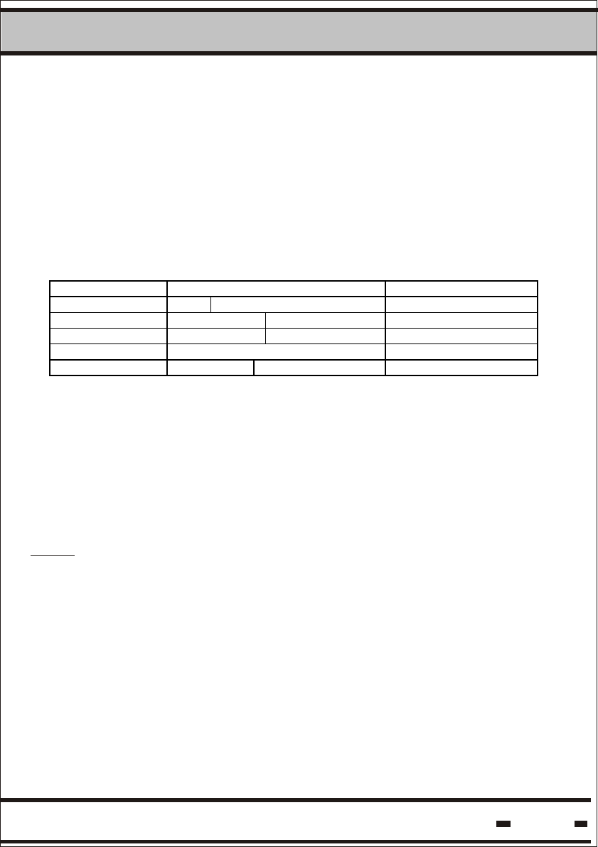
5.3.1. Date & Time
The date and time are represented in Greenwich Mean Time (GMT).
Bits and Bytes assignment:
Byte# / B it# 7 6 5 4 3 2 1 0
0 0 Mi nutes / 10 Mi nutes % 10
1 Mont h %4 Hours/10 Hours % 10
2 Mont h / 4 Days/10 Days % 10
3 Years / 10 Years % 10
4 0 Seconds / 10 Seconds % 10
Minutes range is: 0 - 59.
Hours range is: 0 - 23.
Day range is: 1 - 31.
Month's range is: 1 - 12.
Year's range is: 00 - 99.
Seconds range is: 0 - 59. The seconds field is relevant only for read
& write parameters.
5.3. Parameter's Format.
Most of the parameters have a simple binary value.
Some of them have a specific format.
NOTE: The character "%" denotes the operation of getting the
remainder.
Hi-G-Tek Ltd. Microelectronics & Asset Tracking Technology 69
5System
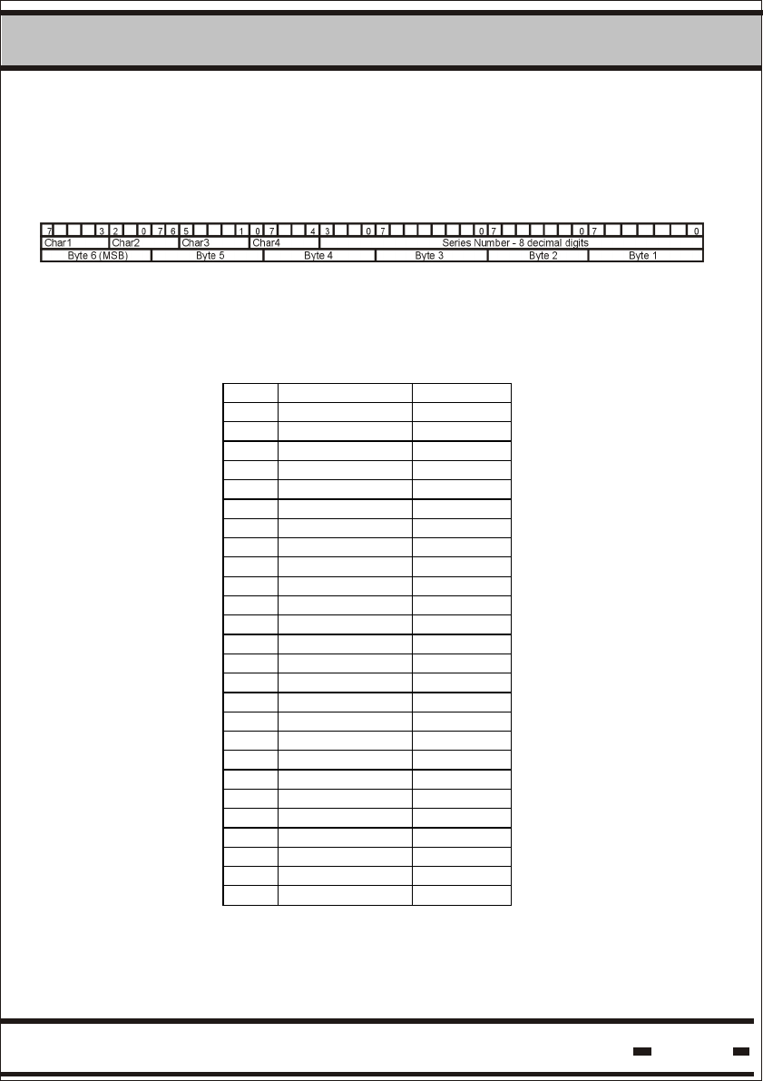
5.3.2. Seal Serial Number (or TF & ID).
The Seal Number is composed of 4 alpha characters and 8 decimal
digits. For example: QWER85723456
The ID is converted from two seperate fields. The Decimal conversion
is from 28 binary value into an 8 digit value.
The alpha characters are converted by using the following conversion
table. Each character is 5 bits:
Binary Text
1 00001 A
2 00010 B
3 00011 C
4 00100 D
5 00101 E
6 00110 F
7 00111 G
8 01000 H
9 01001 I
10 01010 J
11 01011 K
12 01100 L
13 01101 M
14 01110 N
15 01111 O
16 10000 P
17 10001 Q
18 10010 R
19 10011 S
20 10100 T
21 10101 U
22 10110 V
23 10111 W
24 11000 X
25 11001 Y
26 11010 Z
The Seal Number is composed from the TF & ID fields in the
communication protocol. See Commands for further details.
* All other values are illegal.
Hi-G-Tek Ltd. Microelectronics & Asset Tracking Technology
5System
70
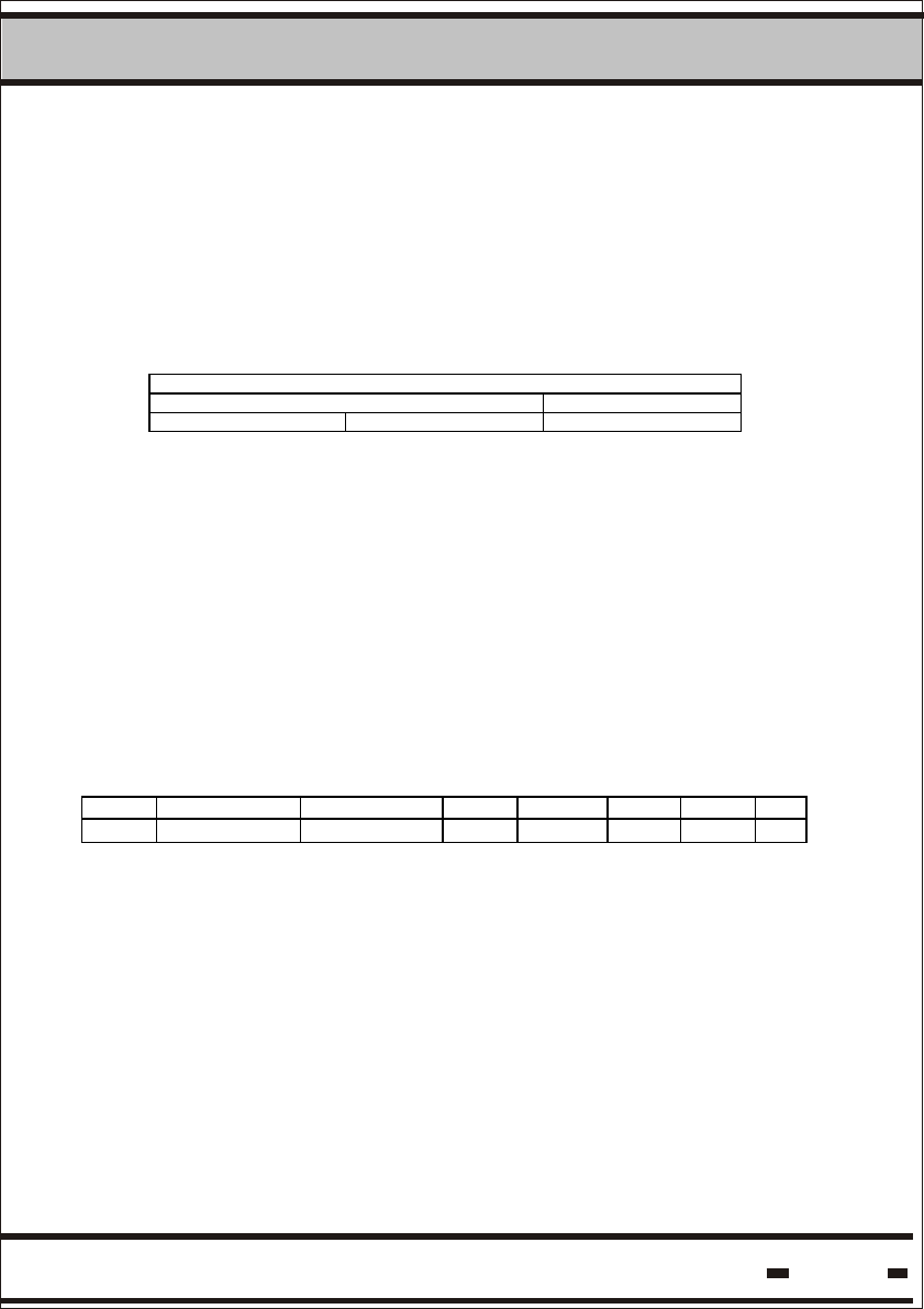
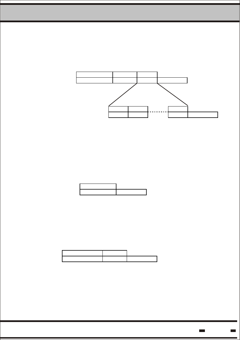
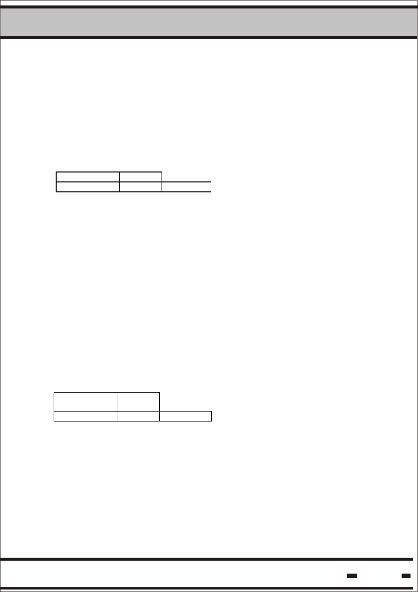
5.3.3. ORG_ID & DEPARTMENT.
ORG_ID is a 3-byte value.
DEPARTMENT is the least significant byte of the ORG_ID parameter.
DEPARTMENT values range from zero to 255 (or 0xFF).
ORG_ID* is composed of the 2 most significant bytes of the ORG_ID
parameter.
ORG_I D
ORG_I D* DEPARTMENT
MSbyte LSbyte
5.3.4 SYSTEM
SYSTEM is a parameter that defines the system characteristics.
Only bit 7 is in use.
Default value of bit 7 is 0.
When bit 7 is set to the value of 1, the FOOTPRINT option comes
into use. This option allows some of the commands to leave the
RD_ID as a footprint in the seal's memory for later tractability
(see paragraph 5.4.4).
5.3.5 MODE.
7 6 5 4 3 2 1 0
CRNC UNSYNC ABMSG N.A N.A N.A N.A N.A
Carrier Sense: In some applications carrier sense should be
used before bursting into the air. The Reader uses this flag
to decide whether it is required or not.
CRNC=0 determines the regular mode: no carrier sense.
CRNC=1 determines the Reader's ability to sense the carrier.
The Reader executes the RF command only after determining
that the air is free.
CRNC

Hi-G-Tek Ltd. Microelectronics & Asset Tracking Technology
5System
71
In unsynchronized commands such as Unsynchronized
Alert, the Reader's receiver must be ON all the time looking
for incoming messages from the seals.
The Reader will set the required mode depending on the
flag's value.
UNSYNC=0 Synchronized mode only.
UNSYNC=1 Unsynchronized mode in use, receiver should
be set to on.
UNSYNC
Burst Messages. This flag indicates whether the alert
messages will be sent following a GET Burst Message or
if the Reader will burst independently with Alert Messages.
BRMSG=0 determines the independent messages burst
mode.
BRMSG=1 indicates the GET Burst Message mode.
ABMSG
5.4 Seal Modes of Operation.
The seal can function in several modes of operation, in accordance
with the application.
5.4.1. Normal Mode.
In the normal mode of operation, the seal is in standby mode most
of the time. When a DataTerminal starts communication, the
transmitted message wakes the seal up.
As explained previously, the method used to establish communication
with the DataReader is different than that used for the DataTerminal.
Using a pre-determined cycle, the seal wakes and performs a channel
monitoring process, searching for the presence of a DataReader. The
frequency of this cycle is notated as Tw. In Normal mode, any event
detected by the seal will be logged in the EVENT Memory.

Hi-G-Tek Ltd. Microelectronics & Asset Tracking Technology
5System
72
5.4.2. Sleep Mode.
It is recommended to use the Sleep mode when a seal is not in use
in order to conserve energy. In this mode, the seal enters an extreme
power-saving mode. To exit this mode, interrogate the seal using the
DataTerminal or use the Hard Wakeup via the DataReader.
When the seal is in Sleep mode no EVENTS will be recorded
until a new SET is performed.
As opposed to the Normal mode, Sleep mode is not an operative mode.
5.4.3. Alert Burst Mode.
The seal should report any detected TAMPER event. The report can
be in the STATUS register of a VERIFY cycle. This approach is good
as long as the system's VERIFY cycle time meets the required system
response time. In applications in which the System Cycle is very long
and the TAMPER event is reported with a long delay, it is possible to
use the Unsynchronized Alert Burst mode. This mode allows the
seal to transmit a burst with a tamper message without waiting for a
Reader Session.
5.4.4. Events Footprint Mode.
A command issued by a Reader may be registered as an event in the
Events Memory by the seal.
This mode should be configured at the Reader before issuing the
command. This mode is useful for tractability purposes. It is possible
to track a specific Reader that performed the command by registering
the Reader ID in the seal's Event Memory with each command.

Hi-G-Tek Ltd. Microelectronics & Asset Tracking Technology
5System
73
5.5.1 Carrier Sense Collision.
If set to 1, the Reader will be activated by the MSB's Carrier Sense
Collision Avoidance ability. This mode of operation is useful if the
Reader is activated individually, without synchronization with other
Readers in the same area.
5.5.2 Unsynchronized Mode.
When seals are operating in Unsynchronized Alert Burst mode, the
Reader's receiver must be ON at all times. This is done by setting bit
6 of the MODE parameter.
5.5. Reader Modes of Operation.
The Reader can work in several modes of operation. This is defined
by the MODE parameter, which is a bit oriented parameter.
Hi-G-Tek Ltd. Microelectronics & Asset Tracking Technology
5System
74
5.6. System Commands.
5.6.1. LSC and Reader Messages.
Table 5.12: LSC Commands and Acknowledge Table:
# Commands Set Command
Code
Comments
1 Wakeup E0 h Wakes the Readers if they are in sleep mode.
2 Execute RF cmnd 20 h Generates an appropriate command from the
Reader to the tags.
3 Get Results 15 h Allows the LSC to retrieve the results
received by the Reader from the tags in the
event of a tag-reader session.
4 Get Status 16 h In the event of a self-contained command, the
Reader will return to its current status.
5 Get Burst Message 1C h This command should be used to retrieve the
alert messages received from the seals when
using the alert burst mode. Alert messages
originating from burst mode are not available
through the regular Get Results command.
6 Reset Reader 14 h Resets a Reader.
7 Write Parameters 06 h ModifiesReader PARAMETERS. Not all
parameters are accessible after the execution
of a LOCK command.
8 Read Parameters 07 h Reads Reader PARAMETERS.
9 BIT 09 h Built-in Execute test
10 Sleep 08 h Places the Reader in Sleep mode of
operation to save power.
11 Unsync Ack 0A h Reserved for unsynchronized responses, see
table 5.2
12 Get Reader’s baud
rate
FF h Allows the LSC to get the Reader’s baud rate.
13 Set Reader baud
rate
FE h Allows the LSC to set the Reader’s baud rate.
14 Set Reader’s
Address
12 h Sets Reader’s address for RS-485 usage
15 Acknowledge OK 92 h Acknowledgment of a message coming from
a Reader and to get the next packet.
16 Acknowledge
Failed
94 h Acknowledgment of an improper message
coming from a Reader.
17 Save Command 0F h Saves one of the above commands for later
execution. This command is used to
synchronize readers.
The following paragraph is a general description of the system
commands.
For a deeper insight see the following:
For low-level RS-485/232 users, see chapter 6.
For high-level DLL users refer to the DLL help file.

Hi-G-Tek Ltd. Microelectronics & Asset Tracking Technology
5System
75
18 Execute Saved
command
17 h Executes a command saved in the Reader.
When it is used in broadcast mode, all the
Readers execute the saved command
simultaneously.
19 Read Channel
Definitions
11 h Allows the Reader to read channel definitions.
20 Write Channe l
Definitions
10 h Allows the Reader to write channel definitions.
Table 5.13: Reader Message Table
# Message Message
Code
Commen ts
1 Wakeup
response
- No response for WAKEUP string
2 Execute RF
cmnd response
20 h
3 Get Results
response
15 h
4 Get Status
response
16 h
5 Get Burst
Message
1C h
6 Reset Reader
response
14 h
7 Write
Parameters
response
06 h
8 Read
Parameters
response
07 h
9 BIT response 09 h
10 Sleep response 08 h
11 Unsync
Message
0A h When a Reader is in unsync mode the
Reader may send an unsynchronized
message. Such a message results from an
alert message coming from a seal.
12 Get Reader’s
baud rate
response
FF h
13 Set Reader
baud rate
response
FE h
Hi-G-Tek Ltd. Microelectronics & Asset Tracking Technology
5System
76
14 Set Reader’s
Address
response
12 h
15 Save Command
response
0F h Saves one of the above commands for
later execution. This command is used to
synchronize readers.
16 Execute Saved
command
response
_ This is a broadcast command. There is no
response to this command.
17 Read Channel
Definitions
response
11 h Allows the Reader to read the definitions
of a channel.
18 Wri te C hanne l
Definitions
response
10 h Allows the Reader to write the definitions
of a channel.
5.6.2. Error Codes.
Errors Error Co de
Unrecognized Command 01 h
MCU Error 02 h
HF Modem Error 03 h
Result is not ready 05 h
HF Modem is not responding 06 h
MCU I/O Error 07 h
HF Modem BIT Error 08 h
Parameter is locked 09 h
Illegal Parameter Code 0A h
5.6.3. Detailed Commands.
5.6.3.1. Wakeup.
5.6.3.1.1. Command Transmission.
Only a very short string needs to be sent by the LSC to wake a
sleeping Reader. The string is detected by the hardware and wakes
the Reader. This is a hardware-oriented command, therefore the
format is different than all the other commands.
Hi-G-Tek Ltd. Microelectronics & Asset Tracking Technology
5System
77
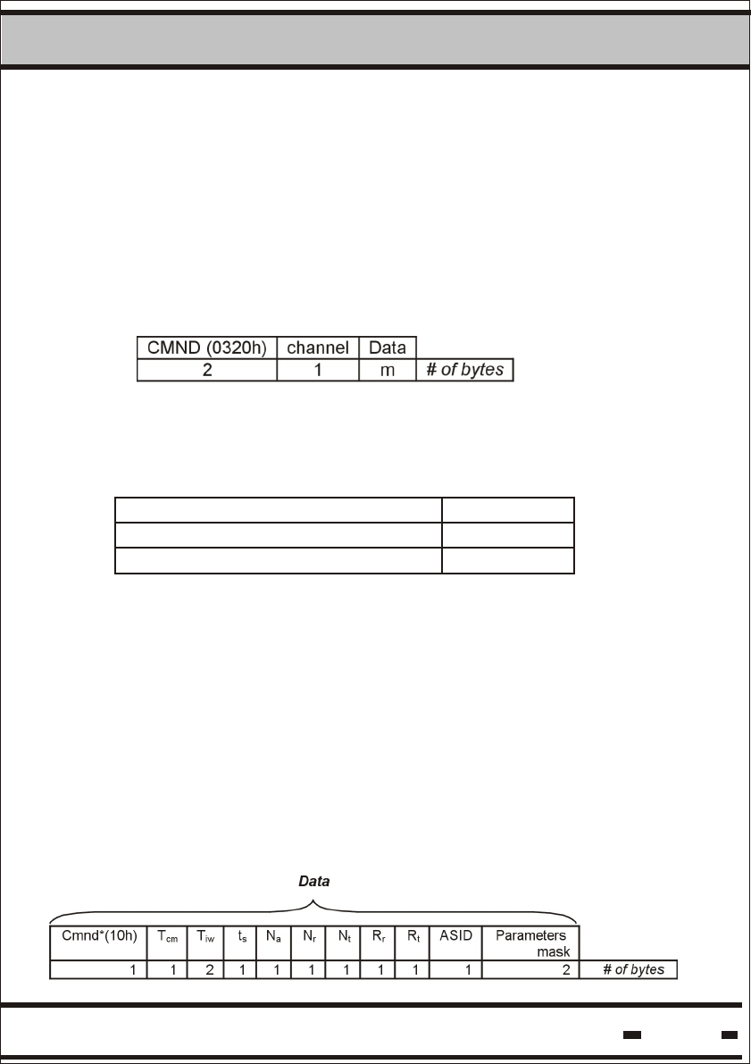
5.6.3.2. Execute RF Command.
5.6.3.2.1. Command Transmission.
This command enables communication sessions with seals. In the
data field the LSC inserts the relevant information allowing the
reader to easily compile the final command string.
LSC > Reader
Where the CMND is the “execute RF command” opcode. Channel
field is one of the following:
Data contains the details of the RF command together with the RF
command opcode.
5.6.3.2.2. Verify.
This command verifies the status of seals that are in the Reader's
receiving zone. This is the most basic and the commonly used
command in the DataSeal system. When executing the Verify
command, the specific parameters for this command must be
defined.
The data field in the Execute RF Command will be:
Code
01h
02h
Channel
Channel 1
Channel 2
Hi-G-Tek Ltd. Microelectronics & Asset Tracking Technology
5System
78
Where:
Cnmd* The RF command's opcode.
Tcm Duration of the calibration message window.
Resolution is in units of 1024 msec.
Tiw The duration of the readers interlace
window. Resolution is in units of 1024 msec.
Ts Duration of a slot for receiving responses
from a tag or a seal. Resolution is in units
of 1024 msec.
Na Number of slots in the Fixed Assignment
Receiving Window.
Nr Number of slots in the Random Access
Receiving Window.
Nt Number of slots in the Alert Receiving
Window.
Rr Number of random retransmissions from a
tag in the Random Access Receiving
Window.
Rt Number of random retransmissions from a
tag in the Alert Receiving Window
ASID A unique and random ID, assigned by the
system to a specific assignment.
Parameters Mask The seal's parameters bit mask which the
tags and seals respond with.
.
Nr+Nt should be lower or equal to 255
The Bit Mask should comply with table 5.14 on the following
page.
Hi-G-Tek Ltd. Microelectronics & Asset Tracking Technology
5System
79
Table 5.14: Parameter Mask
5.6.3.2.3. TAMPER.
Tamper is a command intended solely for interrogation of
tampered Seals.
The command is identical to the Verify command except for
the opcode, which is 11h.
Only the Seals that have detected tamper status respond. The
aim of this command is to provide high priority to tampered Seals
in a crowded Seal environment.
5.6.3.2.4. SET.
Data
SET is the first command used prior to consigning a secured
cargo shipment. A SET command initiates the seal process.
The SET command initiates the seal process, and must be
performed when applying the seal to the cargo, prior to shipment.
* The length of Date & Time in Read and Write parameters is 4
bytes. See paragraph 5.3.1.
Cmnd*
(98h)
P#/PK TF TID CRC TF TID CRC TF TID CRC
1 1 2 4 2 2 4 2 2 4 2 # of bytes

Hi-G-Tek Ltd. Microelectronics & Asset Tracking Technology
5System
80
The Set command can be used on a number of or seals. The
maximum number of seals it can be used on is 8.
Where:
P# The high 4 bits of the first byte in the packet serial
number.
PK The low 4 bits of the first byte in the packet serial
of packets in the BMM string.
At present the packet option is not in use. The value should be 0x11.
5.6.3.2.5. Suspended SET.
The Suspended Set command functions in the same way as the
SET command. The only difference is that the SET command is
executed immediately, while the Seal will execute the Suspended
SET automatically only after the Seal wire has been plugged into
the Seal. The opcode for this command is 99h. The response is the
same response as the SET response but with 19h as the message
type.
5.6.3.2.6. Soft SET.
This command has the same structure as the SET command. The
difference is at the Seal level. In this command the seal marks the
command as an event, but doesn't reset the events memory. The
opcode for this command is 9Ah. The response is the same
response as the SET response but with 1Ah as the message type.
Hi-G-Tek Ltd. Microelectronics & Asset Tracking Technology
5System
81
5.6.3.2.7. Deep Sleep.
The Deep Sleep command allows battery power to be conserved
when seals are in storage and not in use.
5.6.3.2.8. Hard Wakeup.
Hard Wakeup is the command that should be used to wake the
seal from deep sleep mode.
Data
Data
5.6.3.2.9. Start Alert Burst Mode.
Seals usually operate in synchronized mode. In this mode, the
Seals respond to messages from the Reader. In applications where
the frequency of Reader sessions is low, the system's response time
is slow. This has a positive effect on power conservation and other
system considerations.
The seal can be programmed to send an independent asynchronous
alert. In this case, the response time to an alert situation will be short.
Start Alert Burst Mode command can be initiated in two separate
modes: Broadcast mode or Addressed mode.
Data
Hi-G-Tek Ltd. Microelectronics & Asset Tracking Technology 82
5System
Starting specific tags:
Data
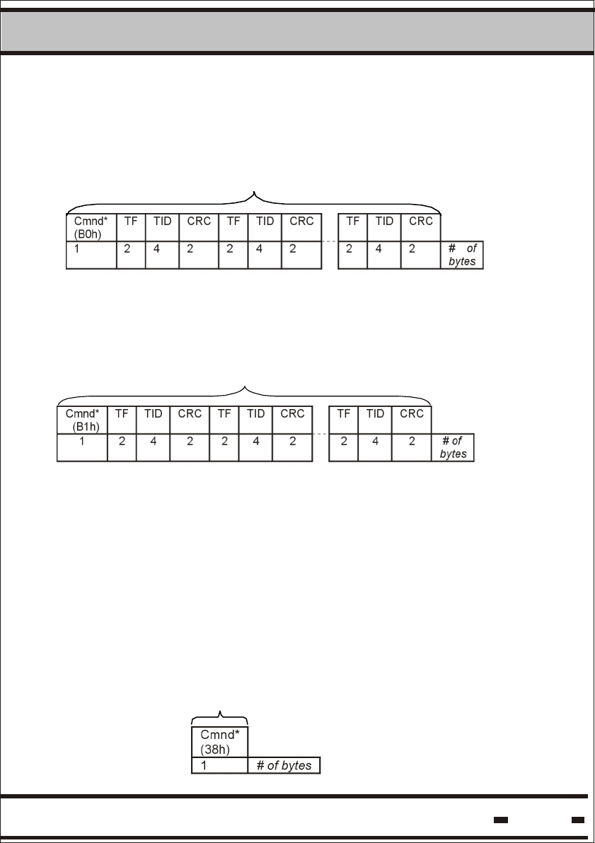
5.6.3.2.10. Stop Alert Burst Mode.
The Start Alert Burst mode operation can be stopped by the Stop
Alert command. The command can be initiated in two separate
modes: Broadcast mode or Individual Seal mode
Stopping all tags:
Data
Data
Data
Stopping specific tags:
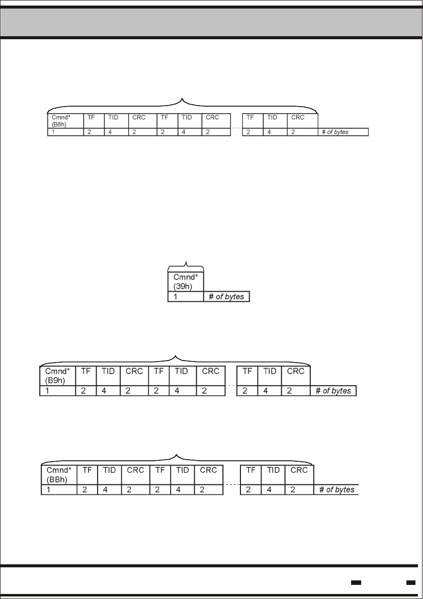
5.6.3.2.11. Ack Alert Burst Mode.
This is to acknowledge receipt of the alert message from specific
seals. The seals will stop bursting until a new alert is detected.
Hi-G-Tek Ltd. Microelectronics & Asset Tracking Technology 83
5System
5.6.3.2.12. Read Data.
Cmnd*
(63h)
TF TID BA
Base address
BL
Block length
1 2 4 2 2 # of bytes
Data
Data
Data
Where:
This is the base address in the memory of the block of BA
data.
This is the data block length.BL
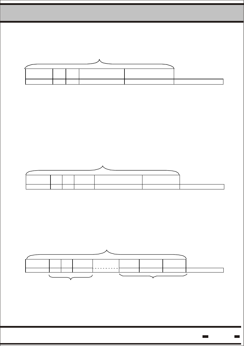
5.6.3.2.13. Write Data
Cmnd*
(68h)
TF TID PK/P# BA
Base address
Data
1 2 4 1 2 m # of bytes
PK/P# = 11h. At present the packets are fixed.
5.6.3.2.14. Reset Data.
Cmnd *
(AAh)
TF TID CRCt
TF8
TID8
CRC8
1 2 4 2 2 4 2 # of bytes
Seal #1 Seal #8
Up to 8 seals can be reset in one cycle.
Hi-G-Tek Ltd. Microelectronics & Asset Tracking Technology 84
5System
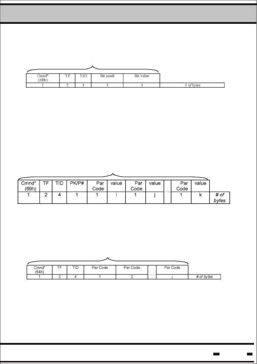
5.6.3.2.15. Set/Reset Status.
Data
Data
Data
Only some of the flags can be set and reset.
Bit mask marks the status bits to be reset.
When the value is set to “0”, this means: “don't modify”.
When the value is set to “1”, this means: “reset value to zero”.
Each bit corresponds to the appropriate bit in the LTS.
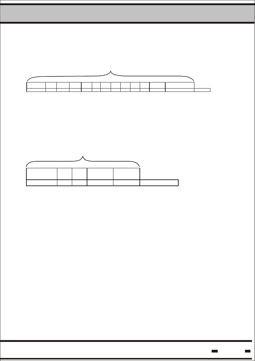
5.6.3.2.16. Write Parameters
TF&TID=00 is for a broadcast command.
PK/P# = 11h. At present the packets are fixed.
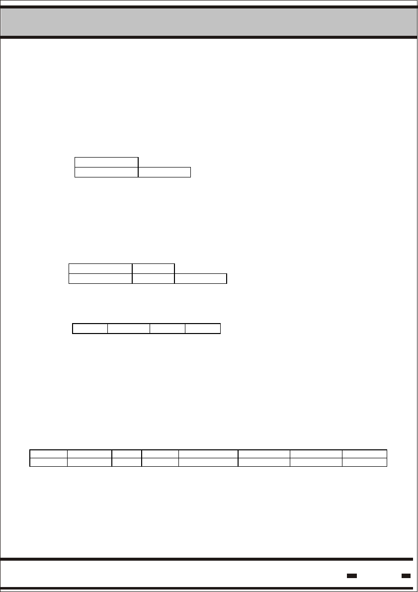
5.6.3.2.17. Read Parameters.
Hi-G-Tek Ltd. Microelectronics & Asset Tracking Technology 85
5System
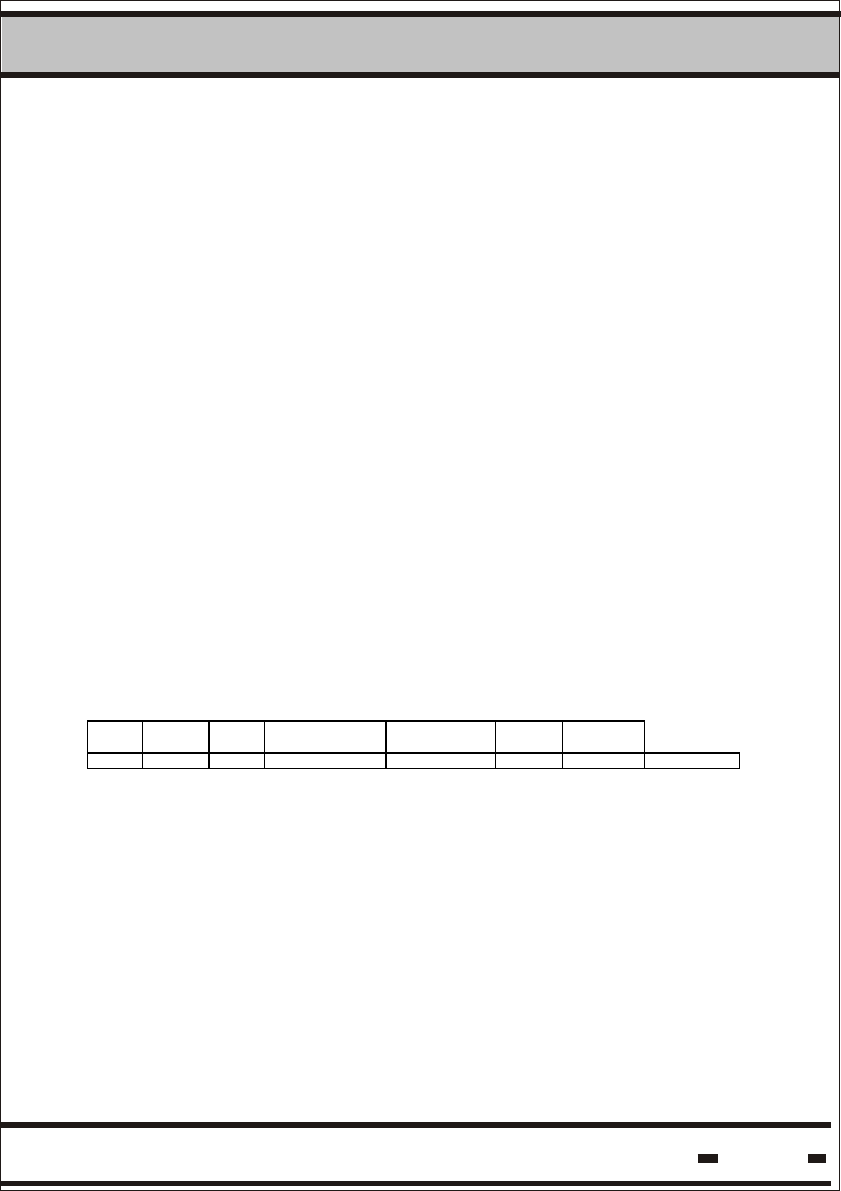
5.6.3.2.18. Addressed Verify.
Cmnd*
(50h)
TF TID Tcm
Tiw
ts
Na
Nr
Nt
Rr
Rt
ASID Parameters mask
1 2 4 1 2 1 1 1 1 1 1 1 2 # of bytes
The following parameters are not applicable to this command:
Na, Nt, Rt.
Data
Data
5.6.3.2.19. Read Events.
Cmnd*
(61h)
TF TID EV# # EV
1 2 4 1 1 # of bytes
Where
is the start event sequential number.EV#
is the number of events to be read from memory.#EV
5.6.3.3. Get Results.
After transmission of a request to execute a command, the system
should wait for a response. The Get Results command allows the
retrieval of the response from the Reader. This command is carried
out at the RS-485 level.
Using the DLL eliminates the need for the use of this command, as
the DLL takes care of the response. For details see the STAR CORE
DLL help file.
Hi-G-Tek Ltd. Microelectronics & Asset Tracking Technology 86
5System
5.6.3.4. Get Status.
5.6.3.4.1. Command transmission.
This command is used to retrieve the status of the READER.
LSC > Reader
CMND(0016h)
2 # of bytes
5.6.3.4.2. Get Status Command Response.
The following string is the general response.
Reader > LSC
MSGT(8016h) R_status
2 4 # of bytes
R_STATUS field is 4 bytes.
Byte A Byte B Byte C Byte D
Byte A represents the status of the main motherboard MCU.
The other bytes represent the RF modem status.
In a general Reader response, the R-Status reply contains bytes
A&B only. In command GET Status the reply contains all the
R-Status bytes.
Byte A:
7 6 5 4 3 2 1 0
UNLOCK 485 PCR PER VCCERR VBERR PMC EDC

Hi-G-Tek Ltd. Microelectronics & Asset Tracking Technology 87
5System
Where:
UNLOCK
485
PCR
PER
VCCERR
VBERR
PMC
EDC
if 0 reader's parameters are locked.
If 1 parameters are unlocked.
If 0 reader is using the RS-232 mode for
communication.
If 1 reader is using the RS-485 mode for
communication.
2
If 0 parameters in the MCU's E ROM are OK.
If 1 parameters were corrupted and successfully
restored.
2
If 0 parameters in the MCU's E ROM are OK.
If 1 parameters are corrupted.
if 0 internal power is OK.
If 1 internal power is not OK.
if 0 internal battery is OK.
If 1 internal battery is not OK.
If 0 program memory in the MCU is OK.
If 1 program memory is corrupted.
a flag indicating that a delayed command was
triggered and is in process.
Byte B:
7 6 5 4 3 2 1 0
Ch1 Ch2 Ch3 Ch4 Ch1err Ch2err Ch3err Ch4err
Where:
Ch1
Ch2
If 0 channel1 is not in use.
If 1 channel1 is in use.
If 0 channel2 is not in use.
If 1 channel2 is in use.

Hi-G-Tek Ltd. Microelectronics & Asset Tracking Technology 88
5System
Ch3
Ch4
If 0 channel 3 is not in use.
If 1 channel 3 is in use.
If 0 channel 4 is not in use.
If 1 channel 4 is in use.
Ch1err
Ch2err
Ch3err
Ch4err
If 0, channel is OK.
If 1, channel is defective. Details are in
byte C. If byte C flags are OK, there is a
communication failure with this channel.
If 0, channel2 is OK.
If 1, channel2 is defective. Details are in
byte C. If byte C flags are OK, there is a
communication failure with this channel.
If 0, channel3 is OK.
If 1, channel3 is defective. Details are in
byte D. If byte D flags are OK, there is a
communication failure with this channel.
If 0, channel4 is OK.
If 1, channel4 is defective. Details are in
byte D. If byte D flags are OK, there is a
communication failure with this channel.
Bytes C&D:
7 6 5 4 3 2 1 0
V CCERR PMC EMC EME V CCERR PMC EMC EME
For ch 1& ch3 For ch2 & ch4
Hi-G-Tek Ltd. Microelectronics & Asset Tracking Technology 89
5System
VCCERR
PMC
EMC
EME
if 0 power is OK.
If 1, power is not OK.
if 0 program memory in the module is OK.
If 1 program memory is corrupted.
2
if 0 E ROM is OK.
2
If 1 E ROM was corrupted and restored.
2
if 0 E ROM is OK.
2
If 1 E ROM was corrupted.
5.6.3.5. Get Burst Message Command
5.6.3.5.1. Command transmission.
This command is used to retrieve the alert messages transmitted
asynchronously by seals that are in alert burst mode.
LSC > Reader
STX #B R# CMND(0 01Ch ) Channel CRC ETX
1 2 2 2 1 2 1 # of bytes
Channel indicates the source channel for the results. The value is
according to the table in paragraph 5.5.2.1.
Hi-G-Tek Ltd. Microelectronics & Asset Tracking Technology 90
5System
5.6.3.5.2. Get Burst Message Command Response.
The following string is the general response.
Reader > LSC
STX #B R# MSGT (xx1Ch ) R_status DATA CRC ETX
1 2 2 2 2 n 2 1 # of bytes
channel
PK
P#
Data*
1 1 1 m # of bytes
Where:
MSGT
DATA
PK
P#
Data*
high byte of MSGT is according the scenario in use.
The lower byte is 1C h.
If the result is not ready the value of this field is 05
hex error code see Paragraph 5.4.
If the result is ready the following applies.
Total number of packets.
Packet number sequence number.
This string contains the Seal's records. This field
should first be retrieved from all packets before
being analyzed.
Seals Records:
Data*1 Data*2 - - - - - - - - - - - - - - Data*PK-1 Data*PK
Seal
record
Seal
record
Seal
record
Seal
record
Seal
record
Seal record
#B Data** #B Data** #B Data** #B Data** #B Data** #B Data**
1 r r r r r r
Hi-G-Tek Ltd. Microelectronics & Asset Tracking Technology 91
5System
Where:
Data**
2 4 1 # of bytes
#B is the number of bytes for a seal record
(including the #B field).
Data** is the data received after executing the RF command
led by TF, TID and Message Type.
If no seal detected:
Data*1
Seal record
#B=0
1
5.6.3.6. Reset Reader.
5.6.3.6.1. Command transmission
This command is used to performa software reset to a readerReader.
LSC > Reader
CMND(0014h)
2 # of bytes
TF TID Message Type Resultant Data
Hi-G-Tek Ltd. Microelectronics & Asset Tracking Technology 92
5System
5.6.3.6.2. Reset Reader Command Response.
The following string is the response.
Reader > LSC
MSGT(xx14h) R_status
2 2 # of bytes
5.6.3.7. Write Parameters.
5.6.3.7.1. Command transmission.
This command enables modification of a parameter's value in the
Reader. It should be clear that not all the parameters are available
for modification. Table 5.2 specifies which parameters may be
modified.
LSC > Reader
CMND(0006h) Dat a
2 n # of bytes
PAR1code value PAR2 code value PARm code value
1 i 1 k 1 l # of bytes

Hi-G-Tek Ltd. Microelectronics & Asset Tracking Technology 93
5System
The following string is the response:
Reader > LSC
MSGT(xx06h) R_status
2 2 # of bytes
5.6.3.8. Read Parameters.
5.6.3.8.1. Command transmission.
This command is to enables the reading of a parameter's value from
the Reader.
LSC > Reader
CMND(0007h) Data
2 n # of bytes
PAR1 code PAR2 code PARm code
1 1 1 # of bytes
5.6.3.7.2. Write Parameters Command Response.
Hi-G-Tek Ltd. Microelectronics & Asset Tracking Technology 94
5System
5.6.3.8.2. Read Parameters Command Response.
5.6.3.9. BIT
5.6.3.9.1. Command Transmission
The following string is the response.
Reader > LSC
LSC > Reader
MSGT(xx07h) R_status Data
2 2 N # of bytes
value Value value
i K m # of bytes
5.6.3.9.2. BIT Command Response.
The following string is the response.
Reader > LSC
MSGT(xx09 h) R_status
2 4 # of bytes
This command generates a set of built-in test procedures.
CMND(0009h)
2 # of bytes
Hi-G-Tek Ltd. Microelectronics & Asset Tracking Technology 95
5System
5.6.3.11. Unsynchronized Reader Message.
5.6.3.11.1. Message Transmission.
If the Reader is in Alert Burst mode, a Burst Alert message may
be transmitted. The following string will be received for each seal.
Reader > LSC
MSGT(800Ah) R_status Data
2 2 n # of bytes
TF TID Command code Short status ORG_ID
2 4 1 1 3 # of bytes
ORG_ID is an option in the response, depending on the seal's
configuration.
5.6.3.10. Sleep.
5.6.3.10.1. Command Transmission.
5.6.3.10.2. Sleep Command Response
This command places the Reader in sleep mode to conserve energy.
The command is useful when the Reader is operating on battery
power. The Reader will wake when it receives a Wakeup command.
CMND(0008h)
2 # of bytes
MSGT(xx08h) R_status
2 4 # of bytes
LSC > Reader
Reader > LSC
The following string is the response:
Hi-G-Tek Ltd. Microelectronics & Asset Tracking Technology 96
5System
5.6.3.12. Get Reader's baud rate.
5.6.3.12.1. Command transmission
This command forces the Reader to report its baud rate.
LSC > Reader
R# (0000) CMND (0 0f f h) R_ID
2 2 4 # of bytes
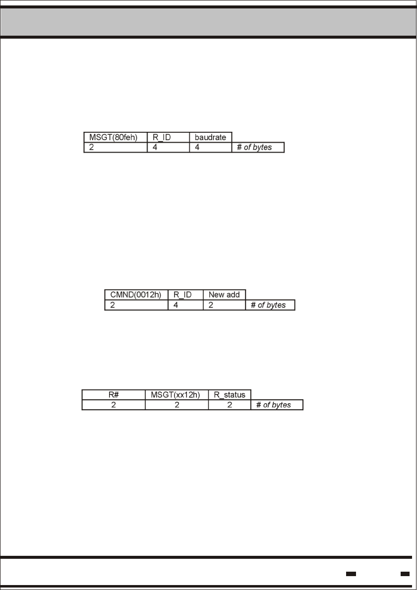
5.6.3.12.2. Get Reader's Baud Rate Response.
The following string is the response.
Reader > LSC
MSGT(80ff h) R_ID baudrate
2 4 4 # of bytes
Baud rate: 2400, 4800, 9600, 19200, 38400
5.6.3.13. Set Reader's Baud Rate.
The baud rate is interpreted as a decimal number translated
into a 32 bit binary number or vise-versa.
5.6.3.11.2. Message Command Ack.
This is an ack issued by the host computer to the Reader is a
RS-232 application.
5.6.3.13.1. Command transmission.
This command forces a new value for the Reader's baud rate.
The actual baud rate update is done after the completion of this
command and receipt of the response.
LSC > Reader
CMND (00f e h) R_ID baudrate
2 4 4 # of bytes
Hi-G-Tek Ltd. Microelectronics & Asset Tracking Technology 97
5System
5.6.3.13.2. Set Reader's Baud Rate Response.
The following string is the response.
Reader > LSC
5.6.3.14. Set Reader's Address.
5.6.3.14.1. Command Transmission.
This command requests the Reader to set its address on the
RS-485 party line. Reader ID is used to distinguish between
Readers sharing the same communication lines.
LSC > Reader
5.6.3.14.2. Set Reader's Address Response.
The following string is the response.
Reader > LSC
The R# is with the new address.
Hi-G-Tek Ltd. Microelectronics & Asset Tracking Technology 98
5System
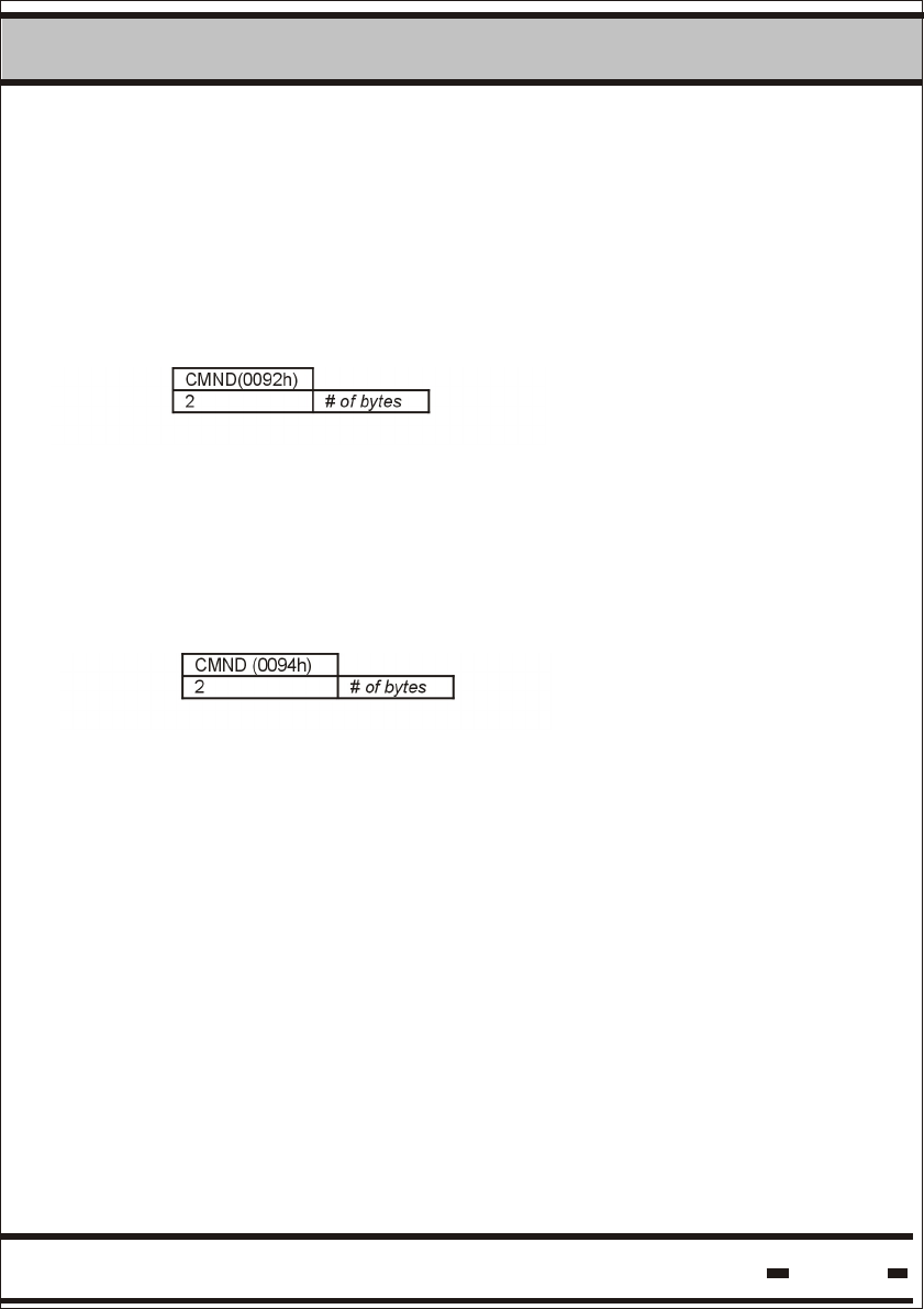
.5.6.3.15. Acknowledge OK.
This string is a one-way LSC string to acknowledge a positive
message coming from the READER. In case of packets, this will
acknowledge the last packet received.
LSC > Reader
5.6.3.16. Acknowledge Failed.
This string is a one-way string to acknowledge a message
indicating a problem originating from the READER.
LSC > Reader
5.6.3.17. Save Command.
5.6.3.17.1. Command Transmission.
In an application where a delayed command execution is required,
the command must first be defined. This is done by saving the
command in the Reader.
Hi-G-Tek Ltd. Microelectronics & Asset Tracking Technology 99
5System
LSC > Reader
CMND(0008h
0Fh)
data
2 # of bytes
phase CMND* Data*
2 2 # of bytes
Where:
Phase is the duration from the end of the “Execute
saved command” and the time required to
execute the saved command. The phase is
in units of 1.024 msec.
CMND* is the command code of the saved command for
delayed execution.
Data* is the relevant data field for the CMND*
Data set to 0 clears the saved command.
5.6.3.17.2. Save Command Response.
The following string is the response.
Reader > LSC
MSGT(XX08h
XX0Fh)
R_status
2 2 # of bytes
Hi-G-Tek Ltd. Microelectronics & Asset Tracking Technology 100
5System
5.6.3.18. Execute Saved Command.
5.6.3.18.1. Command Transmission.
This is a broadcast command sent to all Readers.
There will be no response from any Reader to this command.
LSC > Reader
CMND(0017h) data
2 4*k # of bytes
Reader ID [1] Reader ID [2] Reader ID [k]
4 4
. . . . . . . . . .
4 # of bytes
The data field details the Readers by their IDs
5.6.3.18.2. Execute Saved Command Response.
The following string is the response. There is no response for this
command.
Reader > LSC
STX #B R# MSGT(XX08h) R_status CRC ETX
1 2 2 2 2 2 1 # of bytes
Hi-G-Tek Ltd. Microelectronics & Asset Tracking Technology 101
5System
5.6.3.19. Read Channel Definitions Command.
5.6.3.19.1. Command Transmission.
This command allows reading the definitions of a device.
LSC > Reader
CMND(0011h) channel
21# of bytes
Where:
is the channel number that the device is Channel
connected to. Channel can be 0 to indicate
the MCU, or 1,2 etc for the other channels.
5.6.2.19.2. Read Channel Definitions Response.
The following string is the response.
Reader > LSC
MSGT(XX11h) R_status
file
282 # of bytes
Where:
File is the data file that defines the device.
Hi-G-Tek Ltd. Microelectronics & Asset Tracking Technology 102
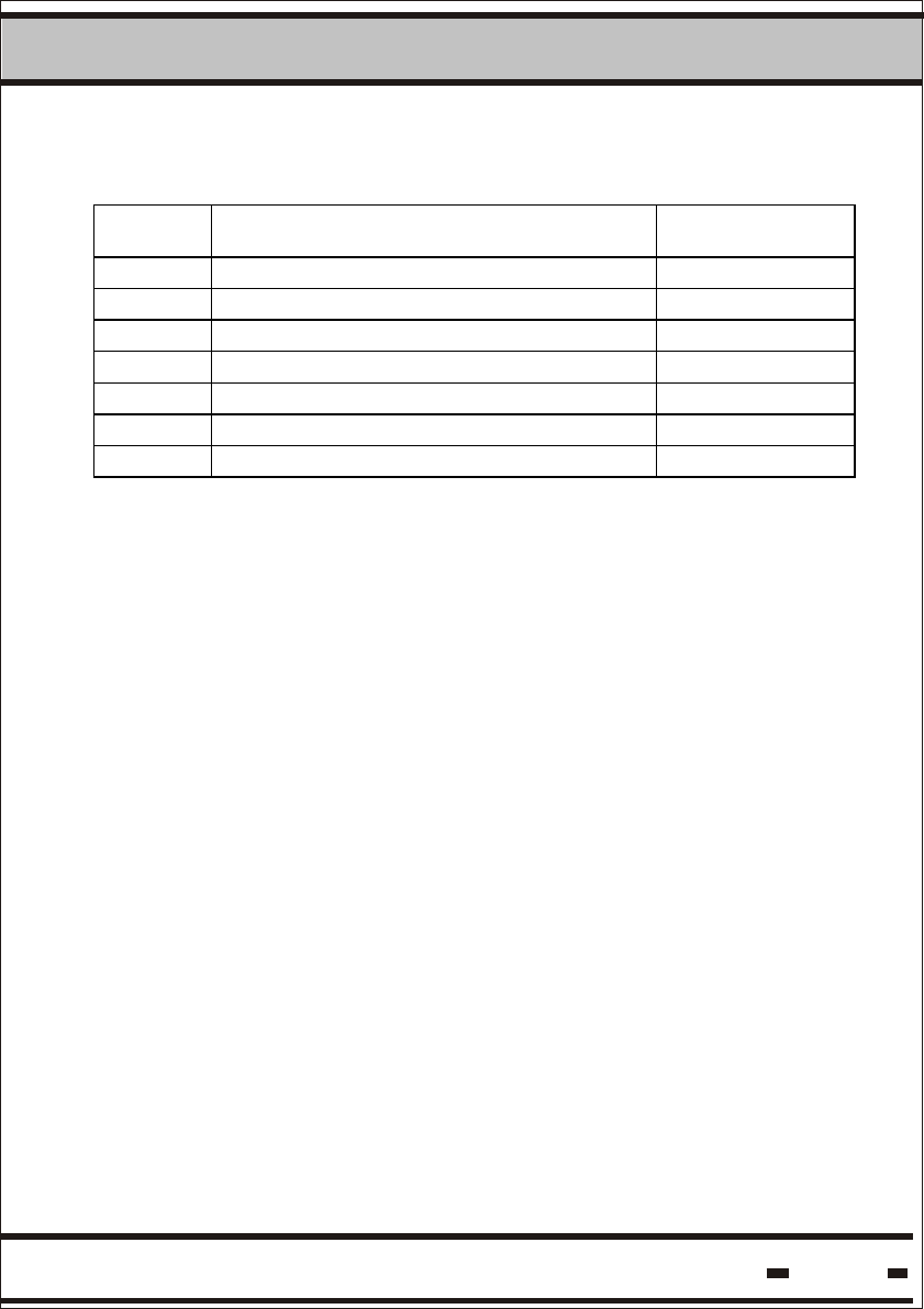
5System
File structure is:
Name Size
[bytes]
1 Part number 16
2 Serial number 16
3 Hardware version 4
4 Production date 10
5 Production batch number 4
5 Description 32
6 Reserved 45
The file is in ASCII format.

Hi-G-Tek Ltd. Microelectronics & Asset Tracking Technology 103
5System
5.7. System Planning.
When planning an application, attention should be paid to both
system operation and topology. Application requirements and
electromagnetic environment characteristics should also be taken
into account.
The system has 2 basic applications: Fixed Reader applications
and Mobile Reader applications.
The Fixed Reader applications are applications where the Readers
are mounted in a fixed site. The Mobile applications are situations
where the Reader is mounted on a vehicle for monitoring seals in
transit.
5.7.1. Electromagnetic Environment.
Radio frequency communications is the basic technology used by
the system. While this is a very robust method for communicating
with remote devices, several issues should be considered when
planning a site:
- Metal walls should not be used to shield the remote devices.
- Communication distance between remote devices is not a constant.
- Communication distance may vary according to one or more of
the following:
Line of sight between devices - existence and clearance.
Proximity to metal objects.
Indoor or Outdoor environment.
Antenna orientation between the devices.
It is recommended to map the site with actual devices for proper
coverage. When planning the site layout, safe margins should be
taken into account to ensure proper operation at all times. Possible
environmental changes should also be considered. System utilities
should be used to test and verify proper and reliable operation.

Hi-G-Tek Ltd. Microelectronics & Asset Tracking Technology 104
5System
5.7.2. System Layout.
Two aspects should be considered when dealing with system layout:
1. Radio Frequency Communication Layout.
2. Line Communication RS-485 or RS-232 Layout.
5.7.2.1 Radio Frequency Communication Layout.
When only one Reader is in use, the previously mentioned
environmental considerations are all that need be taken into
account.
When more then one reader is in use, it should be understood that
in the same area only one Reader can communicate with the seals
at the same time. Interference will be caused by more than one
Reader trying to communicate with the seals in the same period in
time. The Readers should be synchronized using the application
software. Several Readers may operate simultaneously provided
that it has previously been confirmed that they will not interfere with
each other.
Hi-G-Tek Ltd. Microelectronics & Asset Tracking Technology 105
5System
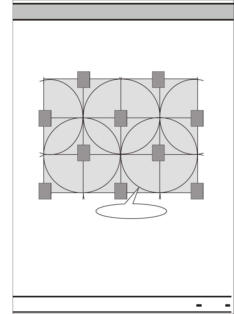
5.7.2.2. Cellular Layout.
Cellular topology should be used to ensure efficient coverage of a
large area. The following drawing illustrates the concept.
Readers must be properly placed to ensure there are no dead zones
within the defined area. Overlaps should be as shown in the above
drawing.
Reader Zone is the term used to describe the area of reliable
communication covered by a Reader. The Reader Zone is a CELL.
As the drawing illustrates, it is extremely important that the
application software controls and synchronizes the Reader's
operation in order to avoid air collisions.
RRRR
Reader Zone
RRRR
RRRRRR
RRRRRR

Hi-G-Tek Ltd. Microelectronics & Asset Tracking Technology 106
5System
5.7.2.3. Reader Session Retransmissions.
Probability calculations were used to estimate Reader Session
retransmissions when creating System Sessions. However, it is
advisable that suitable retransmissions be on hand at the
application level to overcome unpredictable radio interference.
The actual number of retransmissions can be either fixed or
dynamic. These should be set in accordance with the application
requirements and the empirically evaluated on-site electromagnetic
characteristics.
5.7.2.4. Line Communication RS-485 Layout
The connection of many Readers to a Local Site Controller (LSC)
is done via the RS-485 protocol. Up to 32 Readers may be
connected to one COMM Port, depending on the type of RS-485
to RS-232 converter used.
Two topologies can be used:
A long daisy chain connection, where all the readers are
connected in one long line.
A star-type connection, where the readers are split into groups
and each group is connected directly to the converter.
It is recommended that the second alternative be used wherever
possible. A star-type connection provides redundancy in terms of
connections. This alternative is also preferable from the power
supply point of view, as only one power supply for the Readers is
necessary. The power supply should be located near the converter.
When the line is divided into segments, the voltage drop along the
segments is smaller.
Hi-G-Tek Ltd. Microelectronics & Asset Tracking Technology 107
5System
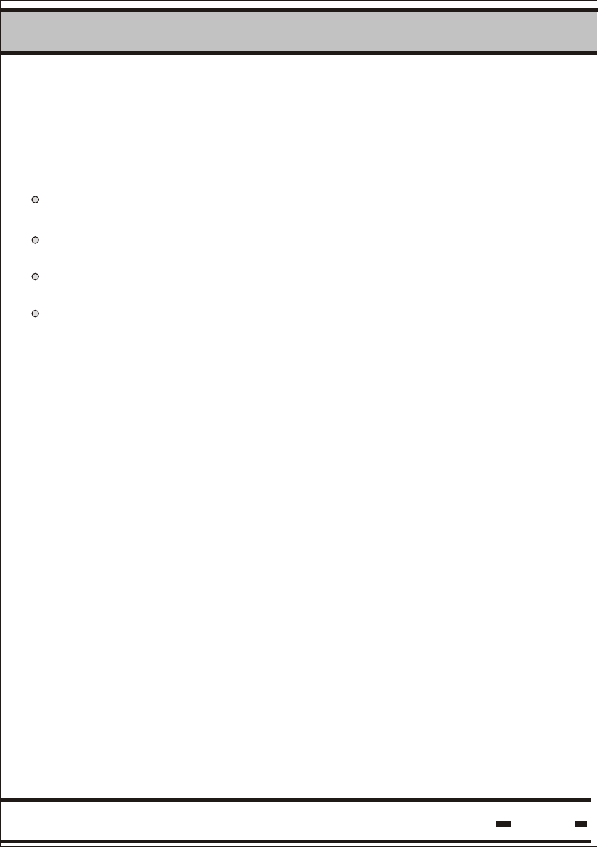
5.8. System Segregation.
When operating the system, several security and operational
considerations should be taken into account:
Ensure that no similar equipment belonging to another company
can operate your system.
Limit unauthorized access between different departments of the
same company.
Allow a Service Provider to supply common services to several
companies.
Allow access to seal subgroups within a company.
5.8.1 Company Segregation by ORG_ID.
ORG_ID is a unique value assigned in production to each
customer. Every device supplied to that company is programmed
with the ORG_ID. All communication sessions are based on a
positive verification of the ORG_ID for complete match between
the devices. There is no way to modify the value of the ORG_ID
and only devices that comply with this request will get full service.
In the event a Reader tries to communicate with a seal without
appropriate ORG_ID and GLOBAL settings, the Illegal ORG_ID
flag in the LONG STATUS will be set. (For information regarding
the GLOBAL setting, see paragraph 5.7.3.).
5.8.2. Department Isolation.
The inter-department relationship works on a similar concept to
that described in section 5.7.1. It is possible to isolate equipment
between departments by using the DEPARTMENT parameter.
The default value of DEPARTMENT is zero. When set to default
settings, all the devices can communicate without any limitations.

Hi-G-Tek Ltd. Microelectronics & Asset Tracking Technology 108
5System
If a value has been inserted, only devices with the same
DEPARTMENT value will establish communication and will get
service. Different departments will have different DEPARTMENT
values. Only a device with DEPARTMENT set to zero will get full
access to all devices. Devices with DEPARTMENT value zero are
considered supervisors. DEPARTMENT values are not factory
pre-sets, and can be set by the customer.
5.8.3. Common Services To Several Companies By A Service Provider.
The ORG_ID setting may comprise a barrier preventing access to
all devices by a Service Provider. The GLOBAL parameter is
designed to allow a Service Provider to service several customers.
If programmed accordingly, the GLOBAL parameter will release the
VERIFY command only to a Service Provider. When the GLOBAL
parameter is in use, the seal will ignore the VERIFY command
except for the parameters marked with * in table 5.2.1. The
GLOBAL parameter is programmed during production. It should
be defined and requested in advance.
5.8.4. How To Use Subgroups Of Seals In A Company.
It may be convenient to the User to subgroup devices into small
groups and then access them by group. The ADI parameter is
used for this operation. The default value of ADI is zero. When
set to default values, the ADI parameter is not in use and full
access is available between all the devices. When ADI is
programmed to a different value, only devices with the same ADI
will communicate. The customer can program ADI on the fly.

Hi-G-Tek Ltd. Microelectronics & Asset Tracking Technology 109
5System
5.8.5: ORG_ID, DEPARTMENT, GLOBAL and ADI: Impact on
seal's response
The following logical statements can summarize seal response:
1. Complete unmatched ORG_ID and GLOBAL is on: Seal will
respond with limited VERIFY command only.
2. Complete unmatched ORG_ID and GLOBAL is off: Seal will
not respond.
3. Complete match of ORG_ID and complete match of
DEPARTMENT and complete match of ADI: Seal will respond
without limitations.
4. Complete match of ORG_ID and unmatched ADI: Seal will
not respond.
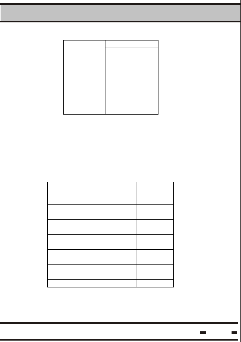
5.9. Seal Memory.
Seal memory is divided into 2 sections: EVENTS MEMORY and
USER DATA.
5.9.1 Events Memory.
This memory stores the events detected by a seal during normal
operation. Memory size is 55 events.
The memory has a FIFO type structure with 2 segments.
The first segment can store 45 Events and is a simple FIFO buffer
with the SET event at the beginning of the buffer.
The second segment can store 10 Events and is a cyclic buffer
with the last events detected.
When this cyclic buffer is overrun, the SCROLL flag in the
LONG STATUS is set.
Hi-G-Tek Ltd. Microelectronics & Asset Tracking Technology 110
5System
SET First segment:
45 Events
Second
segment: 10
Events
With the passing of time, the seal detects events that have been
added to the seal. These additional events may be a result of an
internal procedure or an external intervention.
The following table summarizes Events handled by the seal:
Table 5.15.
Events Event
code
Set 01h
Seal Tampered/
Wire changed (1)
02h
Low battery warning 03h
Seal open or cut (1) 04h
Seal close (1) 05h
Soft Set 07h
RTC Stopped 08h
Database corrupted 09h
Read 0Ah
Time Changed 0Bh
Suspended SET 0Ch
(1) These events are considered TAMPER Events.
Hi-G-Tek Ltd. Microelectronics & Asset Tracking Technology 111
5System
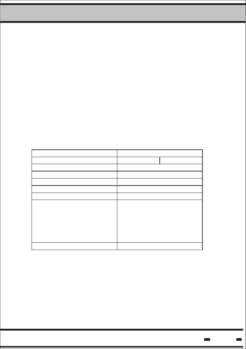
5.9.2. User Data
USER DATA is the memory segment where free data for electronic
manifests can be written and read. To use the USER DATA memory,
the Write and Read Data commands should be used. Memory size is
2K.
Special attention should be taken at the lower portion of the memory.
The DataTerminal supports the lower portion of the USER DATA
memory. The following instructions should be maintained to ensure
full compatibility between the DataReader channel and the
DataTerminal channel:
Memory map of the lower portion.
Address 1 Byte width
Address 0 UDT Version
Address 1 Time & Date
Address 2 Time & Date
Address 3 Time & Date
Address 4 Time & Date
Address 5 Data
.
.
.
.
.
.
.
.
.
.
.
.
Address 52 Data
The value Version is the lower nibble of the address 0 and is the
version of the USERDATA format.
The value UDT is the upper nibble of the address 0 and is a number
assigned the data base configuration by the User.
Using this UDT, the system can perform an integrity check of the
USERDATA in the system.
Hi-G-Tek Ltd. Microelectronics & Asset Tracking Technology 112
5System
Time & Date is the last time and date when the data was written.
Time and Date occupies 4 bytes and the format is:
Date and Time parameter is a counter of 4 bytes with a resolution
of 1 minute.
The zero value starts from the date and time: 00:00:00 01.01.2000
The date and time is set to Greenwich Mean Time (GMT) in
production and is stored under unlock mode.
Bits and Bytes assignment:
Address 7 6 5 4 3 2 1
0
1 0 Mi nutes / 10 Mi nutes % 10
2 Mont h %4 Hours/10 Hours % 10
3 Mont h / 4 Days/10 Days % 10
4 Years / 10 Years % 10
Minutes range is: 0-59.
Hours range is: 0- 23.
Day range is: 1-31.
Month's range is: 1-12.
Year's range is: 00-99.
Seconds range is: 0-59. Seconds field is relevant only for read &
write parameters.
From address 5 to 52 the data is according to the application
design.
5.10. Calculating Reader Session Duration
The total duration of a Reader Session can be calculated by using
the following formula:
Reader Duration=(Thw * 3 + Tbmm + 57) * 1.024 + Trw
Tbmm and Trw are command dependent.

Hi-G-Tek Ltd. Microelectronics & Asset Tracking Technology 113
5System
5.10.1. Calculating Tbmm:
Verify & Tamper Command
Tbmm = 10 msec
Addressed Verify Command
Tbmm = 13 msec
a)
b)
c) SET, Suspended SET, Soft SET, Deep Sleep, Reset Data, Start
Burst Mode, Stop Burst Mode and Acknowledge Burst Mode
Commands.
Tbmm = 4.5 + 4 * N msec
Where N is the number of seals
Read Data Command
Tbmm = 9 msec
Write Command
Tbmm = (17 + Data Size)/2 msec
d)
e)
5.10.2. Calculating Trw:
SET, SOFT SET and RESET DATA Commands
Trw = T * N * 1.024 msec
s
Where T is slot duration and N is the number of seals in a list.
s
a)
b) READ PARAMETERS, WRITE PARAMETERS, READ DATA
and WRITE DATA Commands.
Trw = 42 msec

Hi-G-Tek Ltd. Microelectronics & Asset Tracking Technology 114
5System
c)
d)
e)
READ EVENTS Command:
Trw = ((N + 1)/3) * 50 msec
max
Where N is the maximal number of events.
max
VERIFY, TAMPER and ADDRESSED VERIFY Commands.
Trw = (T + T * (N + N + N )) * 1.024 msec
iws art
Where T T N N N are corresponding parameters of the
iw, s, a, r, t
command.
START BURST MODE FOR ALL SEALS, STOP BURST
Trw = 0