Honeywell 50025034 50025034 User Manual OneWireless XYR 6000 Transmitter
Honeywell International Inc. 50025034 OneWireless XYR 6000 Transmitter
Contents
Pro Install Guide

OneWireless XYR 6000 Transmitter Honeywell Proprietary Rev B 27 August 2008
Professional Installation Guide 50021956 Page 1 of 28
OneWireless XYR 6000 Transmitter
Professional Installation Guide
Document ID: 50021956
Document File: OneWireless XYR 6000 Pro-Install Guide Rev B.doc
Last Revision Date: 27 August 2008
Version: Rev B
Preliminary
This document and the information contained herein are confidential to and the property of Honeywell, Inc. and are made available
only to Honeywell employees for the sole purpose of conducting Honeywell's business. This document, and any copy thereof, and the
information contained herein shall be maintained in strictest confidence; shall not be copied in whole or in part except as authorized
by the employee's manager; and shall not be disclosed or distributed (a) to persons who are not Honeywell employees, or (b) to
Honeywell employees for whom such information is not necessary in connection with their assigned responsibilities. Upon request,
or when the employee in possession of this document no longer has need for this document for the authorized Honeywell purpose,
this document and any copies thereof shall be returned to the employee's manager. There shall be no exceptions to the terms and
conditions set forth herein except as authorized in writing by the responsible Honeywell Vice President.

OneWireless XYR 6000 Transmitter Honeywell Proprietary Rev B 27 August 2008
Professional Installation Guide 50021956 Page 2 of 28
Date Revision Reason
15 October 2007 A Document Release
18 August 2008 B a) Added FCC and IC Compliance Statement information in
Section 3
b) Added IC Compliance Statement and regulations in Section
17
c) Added label information in Section 15
d) Moved Abbreviations and Definitions to Section 1
e) Added Intended Country usage in Section 6
f) Add grounding wire information in Section 10
g) Removed IC ICES-001 statements
h) Added 4 dBi Integral Antenna
i) Added MSG information for FHSS/DSSS radios to Section 5
j) Split Table 10 into two parts (Table 11 and Table 12) so as to
better show differences between FHSS and DSSS EIRP levels
k) Split Table 11 into two parts (Table 13 and Table 14) so as to
better show differences between FHSS and DSSS power
levels
l) Added cable lengths and cable losses to Table 11 and Table
12
m) Added restrictions for units installed in France to Table 11
and Table 12
n) Added and changed notes for Table 11 and Table 12
o) Added Multiple DI and Temperature DI to Table 1
p) Added note in French to Section 3.1
q) Added Table 7 for XYR 6000 with N connectors
r) Added information for installation in Thailand

OneWireless XYR 6000 Transmitter Honeywell Proprietary Rev B 27 August 2008
Professional Installation Guide 50021956 Page 3 of 28
TABLE OF CONTENTS
TABLE OF CONTENTS............................................................................................................................................................. 3
LIST OF FIGURES ..................................................................................................................................................................... 5
LIST OF TABLES ....................................................................................................................................................................... 5
1 DESIGNATION, SCOPE AND PREFACE....................................................................................................................... 6
1.1 DESIGNATION.................................................................................................................................................................. 6
1.2 SCOPE ............................................................................................................................................................................. 6
1.3 PREFACE ......................................................................................................................................................................... 6
1.4 SITE SURVEY................................................................................................................................................................... 6
1.5 ABBREVIATIONS & DEFINITIONS..................................................................................................................................... 8
2 FEDERAL COMMUNICATION COMMISSION (FCC)............................................................................................... 9
2.1 FCC COMPLIANCE STATEMENTS .................................................................................................................................... 9
3 INDUSTRY CANADA (IC) ................................................................................................................................................ 9
3.1 IC COMPLIANCE STATEMENTS........................................................................................................................................ 9
4 RF SAFETY STATEMENT: .............................................................................................................................................. 9
5 FCC AND INDUSTRY CANADA (IC) IDENTIFICATION NUMBERS: .................................................................. 10
5.1 FHSS RADIOS............................................................................................................................................................... 10
5.2 DSSS RADIOS............................................................................................................................................................... 10
6 INTENDED COUNTRY USAGE..................................................................................................................................... 11
6.1 NORTH AMERICA..................................................................................................................................................... 11
6.2 ASIA PACIFIC ............................................................................................................................................................ 11
6.3 EUROPEAN UNION................................................................................................................................................... 11
7 XYR 6000 TRANSMITTER GENERAL DESCRIPTION............................................................................................ 12
7.1 INTENDED USE.............................................................................................................................................................. 12
7.2 XYR 6000 TRANSMITTER DIAGRAMS........................................................................................................................... 12
8 PRODUCT SPECIFICATIONS....................................................................................................................................... 13
8.1 FREQUENCY HOPPING SPREAD SPECTRUM (FHSS) RADIO, 2.4 GHZ............................................................................ 13
8.2 DIRECT SEQUENCE SPREAD SPECTRUM (DSSS) RADIO, 2.4 GHZ................................................................................. 13
8.3 XYR 6000 TRANSMITTER USER ENVIRONMENT ........................................................................................................... 14
8.4 XYR 6000 INSTRUMENT POWER SPECIFICATIONS ........................................................................................................ 14
8.5 WEIGHT ........................................................................................................................................................................ 14
8.6 DIMENSIONS.................................................................................................................................................................. 15
9 CABLES.............................................................................................................................................................................. 16
9.1 XYR 6000 TRANSMITTER WITH RP-TNC CONNECTORS ANTENNA OR LIGHTNING ARRESTOR CABLES....................... 16
9.2 XYR 6000 TRANSMITTER WITH N CONNECTORS ANTENNA OR LIGHTNING ARRESTOR CABLES.................................. 16
9.3 LIGHTNING ARRESTOR TO ANTENNA CABLES............................................................................................................... 16
10 ANTENNA LIGHTNING ARRESTORS.................................................................................................................... 17
11 APPROVED ANTENNA TYPES/GAINS ................................................................................................................... 17
12 EQUIVALENT ISOTROPICALLY RADIATED POWER (EIRP)......................................................................... 18

OneWireless XYR 6000 Transmitter Honeywell Proprietary Rev B 27 August 2008
Professional Installation Guide 50021956 Page 4 of 28
13 EIRP LIMITS................................................................................................................................................................. 18
14 SETTING TX POWER ................................................................................................................................................. 23
15 AGENCY LABEL INFORMATION ........................................................................................................................... 24
15.1 EXTERNAL FCC/IC LABELS.......................................................................................................................................... 24
15.1.1 50016195-001 – Transmitters with FHSS Radios................................................................................................ 24
15.1.2 50016195-002 – Transmitters with DSSS Radios ................................................................................................ 24
15.2 INTERNAL FCC/IC LABELS........................................................................................................................................... 24
16 RF SAFETY, MAXIMUM PERMISSIBLE EXPOSURE (MPE) STATEMENT................................................... 25
17 AGENCY COMPLIANCE............................................................................................................................................ 26
17.1 RADIO AND EMC CERTIFICATIONS ............................................................................................................................... 26
17.1.1 Federal Communication Commission (FCC)....................................................................................................... 26
17.1.2 Industry Canada (IC)........................................................................................................................................... 26
17.1.3 European Telecommunications Standards Institute (ETSI) ................................................................................. 26
17.1.4 Australian communications and media authority (ACMA).................................................................................. 26
17.1.5 Thailand National Telecommunications Commission (TNTC) ............................................................................ 26
17.2 PRODUCT SAFETY AGENCY CERTIFICATIONS................................................................................................................ 27
17.2.1 Canadian Standards Association (CSA)............................................................................................................... 27
17.2.2 Factory Mutual (FM) ........................................................................................................................................... 27
17.2.3 European ATEX Certification (ATEX)................................................................................................................. 28
17.3 EUROPEAN UNION CERTIFICATION (CE-MARK)............................................................................................................ 28
18 REFERENCE DOCUMENTS ...................................................................................................................................... 28

OneWireless XYR 6000 Transmitter Honeywell Proprietary Rev B 27 August 2008
Professional Installation Guide 50021956 Page 5 of 28
LIST OF FIGURES
Figure 1 – XYR 6000 Transmitters showing Right-angle Integral Antenna (left), Straight Integral Antenna
(center) and Remote Antenna connector (right) options__________________________________________ 12
Figure 2 – Dimensions of the XYR 6000 Transmitter with Right-angle -2 dBi Integral Antenna __________ 15
LIST OF TABLES
Table 1 – Model Key Numbers .....................................................................................................................................6
Table 2 –Table of Abbreviations and Definitions..........................................................................................................8
Table 3 – Specifications of FHSS Radio Module in XYR 6000 Transmitter...............................................................13
Table 4 – Specifications of DSSS Radio Module in XYR 6000 Transmitter...............................................................13
Table 5 – User Environment Specifications for XYR 6000 Transmitter......................................................................14
Table 6 – Transmitter to Antenna or Lightning Arrestor Cable Specifications for XYR 6000 with RP-TNC connectors
....................................................................................................................................................................................16
Table 7 – Transmitter to Antenna or Lightning Arrestor Cable Specifications for XYR 6000 with N connectors.......16
Table 8 – Lightning Arrestor to Antenna Cable Specifications...................................................................................16
Table 9 – Lightning Arrestor Specifications for Remote Antenna(s) ..........................................................................17
Table 10 – Approved Antenna Types/Gains...............................................................................................................17
Table 11 – Maximum EIRP Limits for FHSS Radios ..................................................................................................18
Table 12 – Maximum EIRP Limits for DSSS Radios ..................................................................................................19
Table 13 – FHSS Transmit Power Settings for the antennas and cable lengths specified above for FCC, IC, ETSI,
ACMA and TNTC approvals .......................................................................................................................................21
Table 14 – DSSS Transmit Power Settings for the antennas and cable lengths specified above for FCC, IC, ETSI,
ACMA and TNTC approvals .......................................................................................................................................22
Table 15 – Reference documents..............................................................................................................................28

OneWireless XYR 6000 Transmitter Honeywell Proprietary Rev B 27 August 2008
Professional Installation Guide 50021956 Page 6 of 28
1 DESIGNATION, SCOPE AND PREFACE
1.1 Designation
This document is valid for the following XYR 6000 Model Key numbers:
Table 1 – Model Key Numbers
Model Key Number Description
STTW400 Temperature Transmitter (remote sensors)
STTW8 Temperature Transmitter with integral probe
STTW401 Temperature/Digital Inputs
STTW500 Multiple Digital Inputs
STIW600 High Level Analog Input Transmitter
STGW9 Gauge and Absolute Pressure Transmitters
STDW9 Differential Pressure Transmitters
CETW6000M Corrosion Transmitter
Model Selection Guide Table IV selections XF, EF or JF mean that the XYR 6000 has a FHSS radio.
Model Selection Guide Table IV selections XD, ED or JD mean that the XYR 6000 has a DSSS radio.
For the complete model number information, please see the appropriate XYR 6000 Transmitter Model Selection Guides.
1.2 Scope
This document outlines professional installation requirements for the Honeywell XYR 6000 Transmitter for the Honeywell
OneWireless Network. Professional installation is required to comply with certification agency and legal requirements. This
document must be adhered to for all installations of the Honeywell OneWireless XYR 6000 Transmitters.
1.3 Preface
This manual covers professional installation of the Honeywell OneWireless XYR 6000 Transmitters. See the Getting Started
with Honeywell OneWireless, Honeywell OneWireless Planning Guide and Honeywell OneWireless XYR 6000 User’s
Guides for general information on overall system implementation, configuration, and management of these devices.
Since these devices may require that the Transmit (TX) power limit settings for the higher gain antennas be manually adjusted,
then the XYR 6000 is classified by the FCC as a device that must be professionally installed. To be in compliance with FCC
requirements, the radio must be installed with one of approved antennas listed in this document.
1.4 Site Survey
It is assumed for the purposes of this document that a site survey has been performed and that the antenna types, cable lengths
and lightning surge arrestors were appropriately selected per the results of that survey. Any changes to these items as a result
of the actual installation of the XYR 6000 transmitters into the site may require that the TX power setting of the radio board


OneWireless XYR 6000 Transmitter Honeywell Proprietary Rev B 27 August 2008
Professional Installation Guide 50021956 Page 8 of 28
1.5 Abbreviations & Definitions
The term Honeywell XYR 6000 Transmitter will be used to describe the composite unit which includes the Honeywell FHSS
or DSSS RF Module and all subassemblies housed within the XYR 6000 Transmitter enclosure.
Table 2 –Table of Abbreviations and Definitions
ACMA Australian Communications and Media Authority
AD Authentication Device
ATEX Potentially Explosive Atmospheres Directive
AWG American Wire Gauge
Co-located Two or more radios transmitting simultaneously and with less than 20cm
of separation distance.
COTS Commercial Off-The-Shelf
CSA Canadian Standards Association
DCS Distributed Control System
DSSS Direct Sequence Spread Spectrum
EMC Electromagnetic Compatibility
ETSI European Telecommunications Standards Institute
EU European Union
FCC Federal Communications Committee
FHSS Frequency-Hopping Spread Spectrum
FM Factory Mutual
FSK Frequency Shift Keying
GFSK Gaussian Frequency Shift Keying
HLAI High Level Analog Input
IC Industry Canada
IEEE Institute of Electrical and Electronics Engineers
IR Infrared
IrDA Infrared Data Association
LUI Local User Interface
MPE Maximum Permissible Exposure
MSG Honeywell Model Selection Guide
MTBF Mean Time Between Failures
NA North America – United States of America and Canada
NEMA National Electrical Manufacturers Association
PCB Printed Circuit Board
PCI Peripheral Components Interconnect
OQPSK Offset Quadrature Phase-Shift Keying
RAM Random Access Memory
RJ-45 Registered Jack-45
RPN Reverse Polarity N-type
SQA Supplier Quality Assurance
TNTC Thailand National Telecommunications Commission
TX Transmit
Wi-Fi Wireless Local Area Network based on IEEE 802.11 Specifications
WNSIA Wireless Network for Secure Industrial Application

OneWireless XYR 6000 Transmitter Honeywell Proprietary Rev B 27 August 2008
Professional Installation Guide 50021956 Page 9 of 28
2 FEDERAL COMMUNICATION COMMISSION (FCC)
2.1 FCC Compliance Statements
¾ This device complies with Part 15 of FCC Rules and Regulations. Operation is subject to the following two
conditions: (1) This device may not cause harmful interference and (2) this device must accept any interference
received, including interference that may cause undesired operation.
¾ This equipment has been tested and found to comply with the limits for a Class A digital device, pursuant to Part
15 of the FCC Rules. These limits are designed to provide reasonable protection against harmful interference in a
residential installation. This equipment generates, uses, and can radiate radiofrequency energy and, if not
installed and used in accordance with these instructions, may cause harmful interference to radio
communications. Operation of this equipment in a residential area is likely to cause harmful interference in which
case the user will be required to correct the interference at his own expense.
¾ Intentional or unintentional changes or modifications must not be made to the XYR 6000 unless under the
express consent of the party responsible for compliance. Any such modifications could void the user’s authority
to operate the equipment and will void the manufacturer’s warranty.
3 INDUSTRY CANADA (IC)
3.1 IC Compliance Statements
¾ To reduce potential radio interference to other users, the antenna type and its gain should be so chosen that the
equivalent isotropic radiated power (EIRP) is not more than that permitted for successful communication.
¾ Operation is subject to the following two conditions: (1) this device may not cause interference, and (2) this
device must accept any interference, including interference that may cause undesired operation of the device.
¾ This Class A digital apparatus complies with Canadian ICES-003.
¾ French: Cet appareil numérique de la classe A est conforme à la norme NMB-003 du Canada.
4 RF Safety Statement:
To comply with FCC’s and Industry Canada’s RF exposure requirements, the following antenna installation and
device operating configurations must be satisfied.
¾ Remote Point-to-Multi-Point antenna(s) for this unit must be fixed and mounted on outdoor permanent
structures with a separation distance between the antenna(s) of greater than 20cm and a separation distance of at
least 20cm from all persons.
¾ Furthermore, when using integral antenna(s) the XYR 6000 unit must not be co-located with any other antenna or
transmitter device and have a separation distance of at least 20cm from all persons.

OneWireless XYR 6000 Transmitter Honeywell Proprietary Rev B 27 August 2008
Professional Installation Guide 50021956 Page 10 of 28
5 FCC and Industry Canada (IC) Identification Numbers:
5.1 FHSS Radios
• Honeywell XYR 6000 Transmitter FHSS Radio Module Identification
o Honeywell Identification for Class 1 Div 2 RF Modules: 50016517-001
o Honeywell Identification for Intrinsically Safe RF Modules: 50025132-001
• Honeywell XYR 6000 Transmitter FHSS Radio Limited Modular Approval
o Federal Communication Commission Identification for Class 1 Div 2 RF Modules: S5750016517
o Federal Communication Commission Identification for Intrinsically Safe RF Modules: S5750016517
• Honeywell XYR 6000 Transmitter FHSS Radio Limited Modular Approval
o Industry Canada Identification for Class 1 Div 2 RF Modules: 573I-50016517
o Industry Canada Identification for Intrinsically Safe RF Modules: 573I-50016517
5.2 DSSS Radios
• Honeywell XYR 6000 Transmitter DSSS Radio Module Identification
o Honeywell Identification for Intrinsically Safe RF Modules: 50025034-001
• Honeywell XYR 6000 Transmitter DSSS Radio Limited Modular Approval
o Federal Communication Commission Identification for Intrinsically Safe RF Modules: S5750025034
o Industry Canada Identification for Intrinsically Safe RF Modules: 573I-50025034
This information is shown on the label attached to each RF Module.
OneWireless XYR 6000 Transmitter Honeywell Proprietary Rev B 27 August 2008
Professional Installation Guide 50021956 Page 11 of 28
6 INTENDED COUNTRY USAGE
6.1 NORTH AMERICA
Country ISO 3166 2 letter code
UNITED STATES US
CANADA CA
6.2 ASIA PACIFIC
Country ISO 3166 2 letter code
AUSTRALIA AU
THAILAND TH
NEW ZEALAND NZ
6.3 EUROPEAN UNION
Country ISO 3166
2 letter code Country ISO 3166
2 letter code
Austria AT Latvia LV
Belgium BE Liechtenstein LI
Bulgaria BG Lithuania LT
Cyprus CY Malta MT
Czech Republic CZ Netherlands NL
Denmark DK Norway NO
Estonia EE Poland PL
Finland FI Portugal PT
France FR Romania RO
Germany DE Slovakia SK
Greece GR Slovenia SI
Hungary HU Spain ES
Iceland IS Sweden SE
Ireland IE Switzerland CH
Italy IT United Kingdom BG
OneWireless XYR 6000 Transmitter Honeywell Proprietary Rev B 27 August 2008
7 XYR 6000 TRANSMITTER GENERAL DESCRIPTION
7.1 Intended Use
The XYR 6000 Transmitter is a key component of the Honeywell Wireless Network for Secure Industrial Application
(WNSIA). These transmitters are available for various sensor types including Digital Inputs, Temperature, High Level Analog
Inputs, Pressure and Corrosion. The XYR 6000 Transmitter uses a low-powered FHSS or DSSS 2.4 GHz radio to
communicate with Multinode and Gateway devices that are connected to a wired DCS network.
7.2 XYR 6000 Transmitter Diagrams
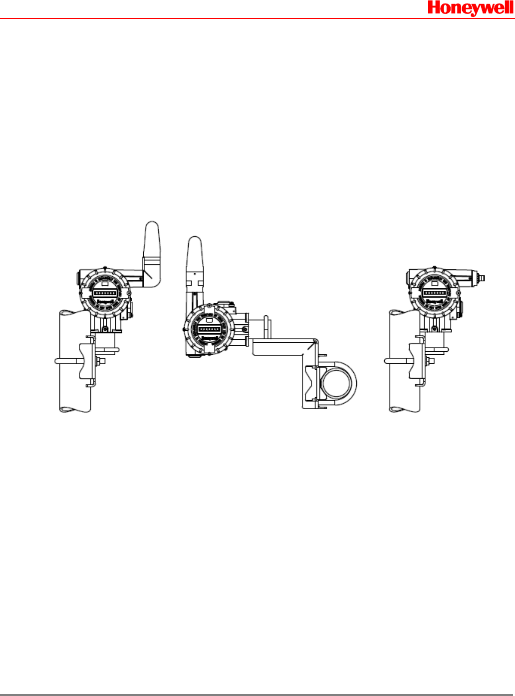
Figure 1 shows unit-level drawings of the XYR 6000 Transmitter antenna options.
`
Figure 1 – XYR 6000 Transmitters showing Right-angle Integral Antenna (left), Straight Integral Antenna
(center) and Remote Antenna connector (right) options
The XYR 6000 Transmitter is available with either an integral antenna or with a remote antenna. Remote antennas are attached
via cables to a connector on the XYR 6000. The integral antennas and/or the remote antenna connectors are not replaceable or
changeable in the field.
Professional Installation Guide 50021956 Page 12 of 28

OneWireless XYR 6000 Transmitter Honeywell Proprietary Rev B 27 August 2008
8 PRODUCT SPECIFICATIONS
8.1 Frequency Hopping Spread Spectrum (FHSS) Radio, 2.4 GHz
Warning! The XYR 6000 Transmitter must be Professionally Installed in accordance with the requirements specified in this
document. See Section 10, for professional installation maximum TX power setting requirements. Only the specified TX
power settings, antenna types and gains and cable lengths (attenuation) as outlined in this document are valid for XYR 6000
Transmitter installations.
Table 3 – Specifications of FHSS Radio Module in XYR 6000 Transmitter
Item Specification
Wireless Standard Frequency Hopping Spread Spectrum (FHSS), 2.4 GHz
Data Rates and Modulation Data Rate: 250 kbps
Modulation: Gaussian Frequency Shift Keying (GFSK)
Frequency Band 2,402 – 2,482 MHz
Module Transmit Power
Maximum: 20 dBm
(Maximum transmit power will vary by channel)
Receive Sensitivity
(typical) -97 dBm
Professional Installation Guide 50021956 Page 13 of 28
8.2 Direct Sequence Spread Spectrum (DSSS) Radio, 2.4 GHz
Warning! The XYR 6000 Transmitter must be Professionally Installed in accordance with the requirements specified in this
document. See Section 10, for professional installation maximum TX power setting requirements. Only the specified TX
power settings, antenna types and gains and cable lengths (attenuation) as outlined in this document are valid for XYR 6000
Transmitter installations.
Table 4 – Specifications of DSSS Radio Module in XYR 6000 Transmitter
Item Specification
Wireless Standard FCC 15.247 / IEEE 802.15.4 Direct Sequence Spread Spectrum (DSSS), 2.4 GHz
Data Rates and Modulation Data Rate: 250 kbps
Modulation: Offset Quadrature Phase-Shift Keying (OQPSK – DSSS)
Frequency Band 2,405 – 2,475 MHz
Module Transmit Power
Maximum: 20 dBm
(Maximum transmit power will vary by channel)
Receive Sensitivity
(typical) -100 dBm

OneWireless XYR 6000 Transmitter Honeywell Proprietary Rev B 27 August 2008
Professional Installation Guide 50021956 Page 14 of 28
8.3 XYR 6000 Transmitter User Environment
Table 5 – User Environment Specifications for XYR 6000 Transmitter
Item Specification
Operating Temperature: –40ºC to +85ºC (–40°F to +185°F)
Storage Temperature: –40ºC to +85ºC (–40°F to +185°F)
Operating Humidity: 0 to 100% RH
8.4 XYR 6000 Instrument Power Specifications
The XYR 6000 Transmitters operate from two (2) D-size 3.6V Lithium batteries. These are joined in series to produce a
maximum voltage of +7.6 Vdc. An optional external +24 Volt power supply option will be available at a future date.
8.5 Weight
The weight of the complete XYR 6000 Transmitter units shall be 14.0 lb. (6.4 kg) maximum. This weight does not include
remote cables and antennas.
OneWireless XYR 6000 Transmitter Honeywell Proprietary Rev B 27 August 2008
Professional Installation Guide 50021956 Page 15 of 28
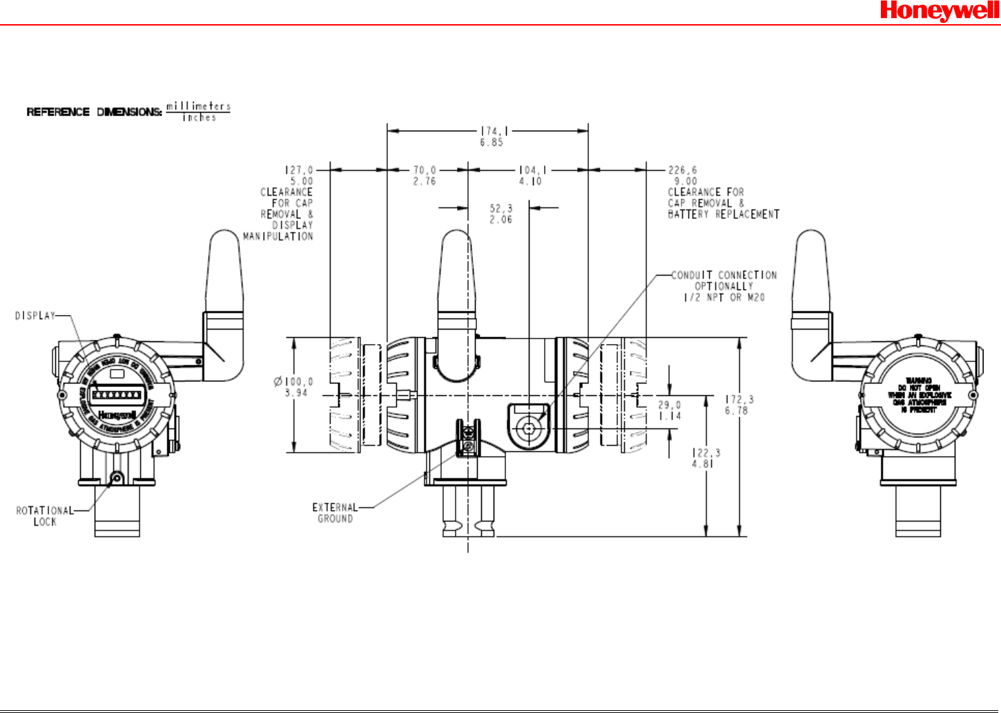
8.6 Dimensions
Figure 2 – Dimensions of the XYR 6000 Transmitter with Right-angle -2 dBi Integral Antenna
Option
OneWireless XYR 6000 Transmitter Honeywell Proprietary Rev B 27 August 2008
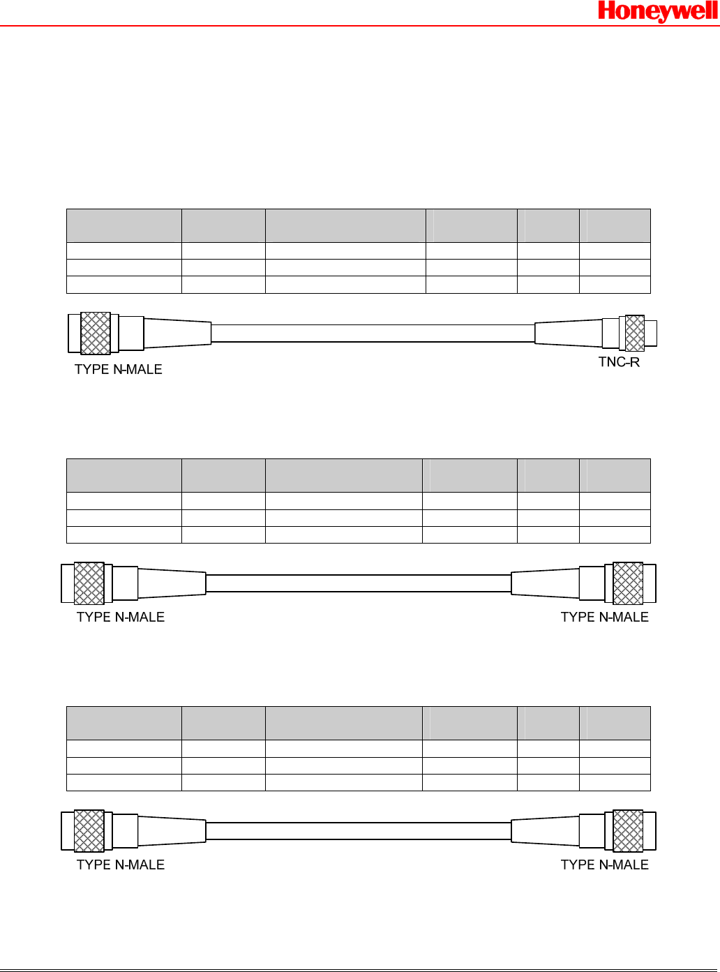
9 Cables
9.1 XYR 6000 Transmitter with RP-TNC Connectors Antenna or Lightning Arrestor
Cables
Table 6 – Transmitter to Antenna or Lightning Arrestor Cable Specifications for XYR 6000 with RP-TNC connectors
Honeywell
Part Number Cable
Type Connector
Type Frequency
(GHz) Length
(m) Loss
(dB)
50018110-001 400 Series RP-TNC to N male 2.4 1 1
50018110-003 400 Series RP-TNC to N male 2.4 3 2
50018110-010 400 Series RP-TNC to N male 2.4 10 3
9.2 XYR 6000 Transmitter with N Connectors Antenna or Lightning Arrestor Cables
Table 7 – Transmitter to Antenna or Lightning Arrestor Cable Specifications for XYR 6000 with N connectors
Honeywell
Part Number Cable
Type Connector
Type Frequency
(GHz) Length
(m) Loss
(dB)
50018278-001 400 Series N male to N male 2.4 1 1
50018278-003 400 Series N male to N male 2.4 3 2
50018278-010 400 Series N male to N male 2.4 10 3
9.3 Lightning Arrestor to Antenna Cables
Table 8 – Lightning Arrestor to Antenna Cable Specifications
Honeywell
Part Number Cable
Type Connector
Type Frequency
(GHz) Length
(m) Loss
(dB)
50018278-001 400 Series N male to N male 2.4 1 1
50018278-003 400 Series N male to N male 2.4 3 2
50018278-010 400 Series N male to N male 2.4 10 3
Professional Installation Guide 50021956 Page 16 of 28
OneWireless XYR 6000 Transmitter Honeywell Proprietary Rev B 27 August 2008
10 Antenna Lightning Arrestors
Table 9 – Lightning Arrestor Specifications for Remote Antenna(s)
Honeywell Part
Number Manufacturer Manufacturer
Part Number
Specification Connector Type Frequenc
y
(GHz)
Attenuatio
n
(dB)
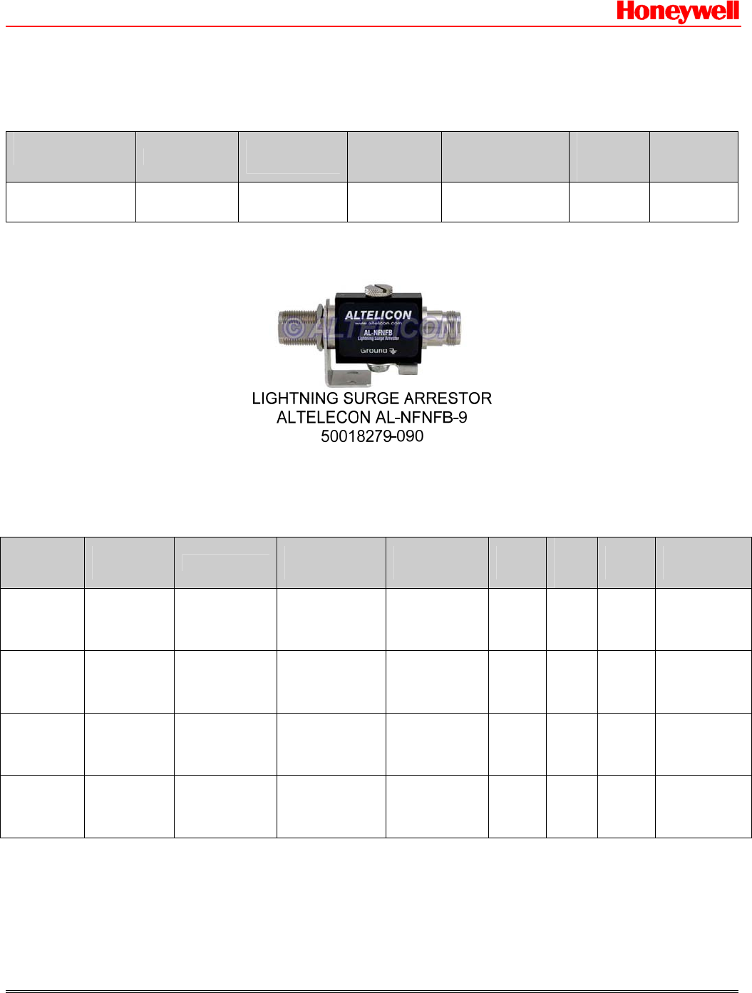
50018279-090 ALTELECON AL-NFNFB-9 50 ohm N Female to N
Female 0 – 3 0.4 (max)
The lightning surge arrestor must be properly grounded in order to perform per specification. Connecting to local ground using
a No. 12 (4 mm2) copper conductor is recommended. See the installation manual for other details.
11 Approved Antenna Types/Gains
Table 10 – Approved Antenna Types/Gains
Antenna
Type Antenna
Application Manufacturer Manufacturer
Part Number Honeywell
Part Number Beam
Width
Peak
Gain
(dBi)
Freq.
(GHz) Agency
Compliance
Omni
(integral) Point to
Multi-Point CENTURIO
N MAF94152 50016185-001 Omni -2
1 2.4 FCC, IC,
ETSI,
ACMA
Omni
(integral) Point to
Multi-Point HYPERLINK WHON511 –
0001 50029933-001 Omni 4 2.4 FCC, IC,
ETSI,
ACMA
Omni
(remote) Point to
Multi-Point HYPERLINK HGV-2409U 50018414-001 Omni 8 2.4 FCC, IC,
ETSI,
ACMA
Directional
(remote) Point to
Multi-Point HYPERLINK HG2414D 50018415-001 25° 14 2.4 FCC, IC,
ETSI,
ACMA
Note:
1. The Centurion antenna listed in Table 10 has a specified gain of 2.2 dBi. Through EIRP measurements performed during
antenna qualification testing, this antenna when installed in the Honeywell Radome and attached to the XYR 6000 Transmitter
body in either the right-angle or straight integral antenna options has an actual gain of -2 dBi. This value is used in
determining the maximum EIRP for Agency Compliance.
Professional Installation Guide 50021956 Page 17 of 28

OneWireless XYR 6000 Transmitter Honeywell Proprietary Rev B 27 August 2008
Professional Installation Guide 50021956 Page 18 of 28
12 Equivalent Isotropically Radiated Power (EIRP)
In radio communication systems, Equivalent Isotropically Radiated Power (EIRP) or, alternatively, Effective Isotropic
Radiated Power, is the amount of power that would have to be emitted by an isotropic antenna (that evenly distributes power in
all directions and is a theoretical construct) to produce the peak power density observed in the direction of maximum antenna
gain. EIRP can take into account the losses in transmission line and connectors and includes the gain of the antenna. The EIRP
is often stated in terms of decibels over a reference power level that would be the power emitted by an isotropic radiator with
an equivalent signal strength. The EIRP allows making comparisons between different emitters regardless of type, size or
form. From the EIRP, and with knowledge of a real antenna's gain, it is possible to calculate real power and field strength
values.
EIRP(dBm) = Radio TX Power (dBm) – Cable Loss (dB) + Antenna Gain(dBi)
Antenna gain is expressed relative to a (theoretical) isotropic reference antenna (dBi).
13 EIRP LIMITS Table 11 – Maximum EIRP Limits for FHSS Radios
Antenna
Type Radio Usage /
Application Freq.
(GHz)
Max.
Ant.
Gain
(dBi)
Min.
Cable
Length
(m)
Min.
Cable
Loss (dB) Agency/Country
Max. Radio
Output
Power
(dBm)
Max.
EIRP
(dBm)
FCC, IC 20 18
ETSI, ACMA, TNTC 20 18
France
2400-2454 MHz 20 18
-2 dBi
Omni
Point to
Multi-
Point Integral 2.4 -2 0 0
France
2454-2482.5 MHz Do not use 3 ---
FCC, IC 20 24
ETSI, ACMA, TNTC 16 20
France
2400-2454 MHz 16 20
4 dBi
Omni
Point to
Multi-
Point Integral 2.4 4 0 0
France
2454-2482.5 MHz Do not use 3 ---
FCC, IC 18 25
ETSI, ACMA, TNTC 13 20
France
2400-2454 MHz 13 20
8 dBi
Omni
Point to
Multi-
Point Remote 2.4 8 1 1
France
2454-2482.5 MHz Do not use 3 ---
FCC, IC 12 25
ETSI, ACMA, TNTC 7 20
France
2400-2454 MHz 7 20
14 dBi
Directiona
l
Point to
Multi-
Point Remote 2.4 14 1 1
France Do not use 3 ---

OneWireless XYR 6000 Transmitter Honeywell Proprietary Rev B 27 August 2008
Professional Installation Guide 50021956 Page 19 of 28
2454-2482.5 MHz
Table 12 – Maximum EIRP Limits for DSSS Radios
Antenna
Type Radio Usage /
Application Freq.
(GHz)
Max.
Ant.
Gain
(dBi)
Min.
Cable
Length
(m)
Min.
Cable
Loss (dB) Agency/Country
Max. Radio
Output
Power
(dBm)
Max.
EIRP
(dBm)
FCC, IC 20 18
ETSI, ACMA, TNTC 14 12
France
2400-2454 MHz 14 12
-2 dBi
Omni
Point to
Multi-
Point Integral 2.4 -2 0 0
France
2454-2482.5 MHz Do not use 3 ---
FCC, IC 20 24
ETSI, ACMA, TNTC 8 12
France
2400-2454 MHz 8 12
4 dBi
Omni
Point to
Multi-
Point Integral 2.4 4 0 0
France
2454-2482.5 MHz Do not use 3 ---
FCC, IC 18 25
ETSI, ACMA, TNTC 5 12
France
2400-2454 MHz 5 12
8 dBi
Omni
Point to
Multi-
Point Remote 2.4 8 1 1
France
2454-2482.5 MHz Do not use 3 ---
FCC, IC 14 25
ETSI, ACMA, TNTC -2 11
France
2400-2454 MHz -2 11
14 dBi
Directiona
l
Point to
Multi-
Point Remote 2.4 14 1 1
France
2454-2482.5 MHz Do not use 3 ---
Notes for Table 11 and Table 12:
1. The values in the above tables have been determined through agency certification testing.
2. The following shall apply for antenna type, frequency range, application/usage and agency/country compliance:
• Antenna gains above the maximum values shown shall not be used.
• Cable length/loss below the minimum values shown shall not be used.
• Maximum overall radio output power shown shall not be exceeded.
• Maximum EIRP values shown above shall not be exceeded.
3. France restricts outdoor use to 10mW (10 dBm) EIRP in the frequency range of 2,454-2,483.5 MHz. Installations
in France must limit EIRP to 10 dBm for operating modes utilizing frequencies in the range of 2,454 – 2,483.5MHz.
For this reason, Honeywell does not recommend configuring frequency hopping modes that use this frequency range.
For installations in France, use only the following OneWireless Frequency Hopping (FH) Mode Selections: EU
Channel #1, EU Channel #7, NA/EU Guard Bands and NA/EU Channel 3 (FH Mode selections #4, 5, 8 and 10).

OneWireless XYR 6000 Transmitter Honeywell Proprietary Rev B 27 August 2008
Professional Installation Guide 50021956 Page 20 of 28
4. Industry Canada Compliance Statement: This device has been designed to operate with the antenna types listed in this
document, and having a maximum gain of 14 dBi. Antenna types not included in this list or having a gain greater than
14 dBi are strictly prohibited for use with this device. The required antenna impedance is 50 ohms.

OneWireless XYR 6000 Transmitter Honeywell Proprietary Rev B 27 August 2008
Professional Installation Guide 50021956 Page 21 of 28
Table 13 – FHSS Transmit Power Settings for the antennas and cable lengths specified above for FCC, IC, ETSI,
ACMA and TNTC approvals
Description Model Selection Guide Table III 1 Cable(s) Length 2
(m)
TX Power Setting for
ETSI/ACMA/TNTC 3
(dBm)
TX Power Setting
for FCC/IC 3
(dBm)
-2 dBi Integral
Antenna V 0 0 0 0 or S 0 0 0 0 N/A 16 16
4 dBi Integral Antenna R 0 0 0 0 or H 0 0 0 0 N/A 16 16
8 dBi Omni w/o
suppressor M 0 1 0 0 or M 0 3 0 0 1, 3 13 16
8 dBi Omni w/o
suppressor M 1 0 0 0 10 15 16
8 dBi Omni with
suppressor M 0 1 0 1 1+1 15 16
8 dBi Omni with
suppressor M 0 1 0 3 or M 0 3 0 3 or M 0 3 10 or
M 0 3 0 1 or M 1 0 0 3 or M 1 0 1 0 1+3, 3+3, 3+10,
3+1, 10+3, 10+10 16 16
14 dBi directional w/o
suppressor D 0 1 0 0 or D 0 3 0 0 1,3 7 12
14 dBi directional w/o
suppressor D 1 0 0 0 10 9 14
14 dBi directional with
suppressor D 0 1 0 1 1+1 9 14
14 dBi directional with
suppressor D 0 1 0 3 or D 0 3 0 1 or D 0 3 0 3 1+3, 3+1, 3+3 10 15
14 dBi directional with
suppressor D 0 3 1 0 or D 1 0 0 3 3+10, 10+3 11 16
14 dBi directional with
suppressor D 1 0 1 0 10+10 13 16

OneWireless XYR 6000 Transmitter Honeywell Proprietary Rev B 27 August 2008
Professional Installation Guide 50021956 Page 22 of 28
Table 14 – DSSS Transmit Power Settings for the antennas and cable lengths specified above for FCC, IC, ETSI,
ACMA and TNTC approvals
Description Model Selection Guide Table III 1 Cable(s) Length 2
(m)
TX Power Setting for
ETSI/ACMA/TNTC 3
(dBm)
TX Power Setting
for FCC/IC 3
(dBm)
-2 dBi Integral
Antenna V 0 0 0 0 or S 0 0 0 0 N/A 14 16
4 dBi Integral Antenna R 0 0 0 0 or H 0 0 0 0 N/A 8 16
8 dBi Omni w/o
suppressor M 0 1 0 0 or M 0 3 0 0 1, 3 5 16
8 dBi Omni w/o
suppressor M 1 0 0 0 10 7 16
8 dBi Omni with
suppressor M 0 1 0 1 1+1 6 16
8 dBi Omni with
suppressor M 0 1 0 3 or M 0 3 0 3 or M 0 3 10 or
M 0 3 0 1 or M 1 0 0 3 or M 1 0 1 0 1+3, 3+3, 3+10,
3+1, 10+3, 10+10 7 16
14 dBi directional w/o
suppressor D 0 1 0 0 or D 0 3 0 0 1,3 -2 12
14 dBi directional w/o
suppressor D 1 0 0 0 10 0 14
14 dBi directional with
suppressor D 0 1 0 1 1+1 -1 14
14 dBi directional with
suppressor D 0 1 0 3 or D 0 3 0 1 or D 0 3 0 3 1+3, 3+1, 3+3 -2 15
14 dBi directional with
suppressor D 0 3 1 0 or D 1 0 0 3 3+10, 10+3 2 16
14 dBi directional with
suppressor D 1 0 1 0 10+10 3 16
Notes for Table 13 and Table 14:
1. The Model Number of any instrument may be found on the identification name plate located on the outside of the
XYR 6000 transmitter. The values in the Cable(s) Length column represent those customer selections from Table III
of the XYR 6000 Model Selection Guides.
2. In the Cable(s) Length column, entries of the form “X+X” indicate that there are two cables between the XYR 6000
and the remote antenna, with a lightning surge arrestor used to connect the two cables together. Entries of the form
“X” mean that there is a single cable and that no lightning surge arrestor is used. For entries of the form “X+X”; the
first value is the length of the cable between the instrument and the arrestor while the second value is the length of the
cable between the arrestor and the remote antenna. All cables are 400 series types as specified in Table 6 and Table 7.
3. TX Power is set by the Honeywell factory producing the XYR 6000 to the values shown in the above tables. These
factory values are determined by the customer’s model number selections in Table III for antenna type, cables and the
lightning suppressor. If the cable lengths, antenna type or the use of a lightning surge arrestor are changed in the field
away from the Model Number listed on the instrument, then the TX power setting should likewise be changed per the
tables above to match the new antenna/cable/arrestor selections.
4. The TX Power Setting values given in Table 12 and Table 13 represent the power produced by the Radio circuit
within the RF Module. These TX Power Setting values do not include antenna gains nor do they include losses caused
by cables, connectors and lightning arrestors. When these external gains and losses are included, using the TX power
values in Table 13 and Table 14 ensures that the EIRP will not exceed the maximum limits as given in Table 11 and
Table 12.

OneWireless XYR 6000 Transmitter Honeywell Proprietary Rev B 27 August 2008
Professional Installation Guide 50021956 Page 23 of 28
14 Setting TX Power
Warning! The XYR 6000 Transmitter must be Professionally Installed in accordance with the requirements specified in this
document. Only the specified power settings, antenna types and gains and cable lengths (attenuation) as outlined in this
document are valid for XYR 6000 Transmitter installations.
TX Power setting is accomplished with the Authentication Device when a special application (app) is installed. This app is
considered to be Honeywell sensitive material and is made available only to the qualified Professional Installer.
When this app is installed in the AD, the XYR 6000 TX power setting, normally a read-only parameter, becomes a read/write
parameter.
Using the virtual keyboard in the Device Local Configuration AD routine to manipulate the local user interface (LUI),
navigate to the TX_POWER display in the RADIO setup group. The XYR 6000 as shipped from the factory should show a
TX Power value consistent with those given in Table 13 and Table 14.
The TX Power adjustment feature is provided for Professional Installers to adjust the XYR 6000 TX power to match the
specific selection of antenna and cables at the installation site and keep the total TX power under the regulatory thresholds.
OneWireless XYR 6000 Transmitter Honeywell Proprietary Rev B 27 August 2008
15 Agency Label Information
The following information shall be clearly and permanently labeled on the XYR 6000 Transmitter unit:
15.1 External FCC/IC Labels
15.1.1 50016195-001 – Transmitters with FHSS Radios
THIS DEVICE COMPLIES WITH PART 15 OF THE FCC RULES. OPERATION IS SUBJECT TO THE FOLLOWING TWO
CONDITIONS: (1) THIS DEVICE MAY NOT CAUSE HARMFUL INTERFERENCE, AND (2) THIS DEVICE MUST ACCEPT ANY
INTERFERENCE RECEIVED, INCLUDING INTERFERENCE THAT MAY CAUSE UNDESIRED OPERATION.
FCC ID: S5750016517 / IC: 573I-50016517
15.1.2 50016195-002 – Transmitters with DSSS Radios
THIS DEVICE COMPLIES WITH PART 15 OF THE FCC RULES. OPERATION IS SUBJECT TO THE FOLLOWING TWO
CONDITIONS: (1) THIS DEVICE MAY NOT CAUSE HARMFUL INTERFERENCE, AND (2) THIS DEVICE MUST ACCEPT ANY
INTERFERENCE RECEIVED, INCLUDING INTERFERENCE THAT MAY CAUSE UNDESIRED OPERATION.
FCC ID: S5750025034 / IC: 573I-50025034
15.2 Internal FCC/IC Labels
50021957-001 50021957-002 50021957-003
RF MOD 50016517-001
FCC ID: S5750016517
IC: 573I-50016517
Professional Installation Guide 50021956 Page 24 of 28
RF MOD 50025132-001
FCC ID: S5750016517
IC: 573I-50016517
RF MOD 50025034-001
FCC ID: S5750025034
IC: 573I-50025034

OneWireless XYR 6000 Transmitter Honeywell Proprietary Rev B 27 August 2008
Professional Installation Guide 50021956 Page 25 of 28
16 RF Safety, Maximum Permissible Exposure (MPE) statement
To comply with FCC’s and Industry Canada’s RF exposure requirements, the following antenna installation and device
operating configurations must be satisfied:
Remote antenna(s) for this unit must be fixed and mounted on outdoor permanent structures with a separation distance
between the antenna(s) of at least 20 cm and a separation distance of at least 20 cm from all persons.
When using integral antenna(s) the XYR 6000 Transmitter unit must not be co-located with any other antenna or transmitter
device and have a separation distance of at least 20 cm from all persons.

OneWireless XYR 6000 Transmitter Honeywell Proprietary Rev B 27 August 2008
Professional Installation Guide 50021956 Page 26 of 28
17 Agency Compliance
17.1 Radio and EMC Certifications
17.1.1 Federal Communication Commission (FCC)
¾ Specification: FCC Part 15.247 Subpart B for unintentional radiators
¾ Specification: FCC Part 15.247 Subpart C for intentional radiators
17.1.2 Industry Canada (IC)
¾ Method: RSS-210, Issue 7
¾ RSS-Gen, Issue 2
¾ ICES-003, Issue 4
17.1.3 European Telecommunications Standards Institute (ETSI)
¾ Emissions Specification and Method: EN 300 328 V1.7.1
¾ Emissions Spec and Method: EN 301 893 V1.3.1
¾ Immunity Specification: EN 301 489-17 V1.2.1
¾ Immunity Method: EN 301 489-1 V1.6.1
¾ Product Standard: IEC61326-1 (1st Edition, 2002-02, Industrial Locations)
17.1.4 Australian communications and media authority (ACMA)
¾ Specification: AS NZS 4771-2000
17.1.5 Thailand National Telecommunications Commission (TNTC)
¾ Specification: เรื่อง เครื่องวิทยุคมนาคมและสถานีวิทยุคมนาคมที่ไดรับยกเวนไมตองไดรับใบอนุญาต (Specification for
non-licensed Radio and Radio Station Telecommunications)

OneWireless XYR 6000 Transmitter Honeywell Proprietary Rev B 27 August 2008
Professional Installation Guide 50021956 Page 27 of 28
17.2 Product Safety Agency Certifications
17.2.1 Canadian Standards Association (CSA)
ANSI/ISA S82.02.01 (61010-1) CSA C22.2 No. 1010-1, ANSI/UL 61010-1, Safety Standard for Electrical Equipment for
Measurement, Control and Laboratory Use – Part 1: General Requirements
C22.2 No. 0, General Requirements - Canadian Electrical Code, Part II
C22.2 No. 25, Enclosures for Use in Class II, Group E, F & G Hazardous Locations
C22.2 No. 94, Special Purpose Enclosures, Industrial Products
C22.2 No. 14, Industrial Control Equipment, Industrial Products
C22.2 No. 30, Explosion Proof Enclosures for Use in Hazardous Locations, Industrial Products
C22.2 No. 157, Intrinsically Safe and Non-Incendive Equipment for Use in Hazardous Locations
C22.2 No. 213, Non-Incendive Electrical Equipment for Use in Class I, Division 2 Hazardous Locations
E60079-0, Electrical Apparatus for Explosive Gas Atmospheres, Part 0: General Requirements
E60079-1, Electrical Apparatus for Explosive Gas Atmospheres, Part 1: Flameproof “d”
E60079-11, Electrical Apparatus for Explosive Gas Atmospheres, Part 11: Intrinsic Safety "i"
E60079-15, Electrical Apparatus for Explosive Gas Atmospheres, Part 15: Electrical Apparatus With Type of Protection "n"
• Temperature code: T4 (135°C) based on the maximum specified ambient of 85°C.
17.2.2 Factory Mutual (FM)
ANSI/ISA S82.02.01 (61010-1) CSA C22.2 No. 1010-1, ANSI/UL 61010-1, Safety Standard for Electrical Equipment for
Measurement, Control and Laboratory Use – Part 1: General Requirements
FM electrical equipment requirements for use within Class I, Division 2, Groups A, B, C and D/Zone 2, Group IIC Hazardous
Locations.
Factory Mutual Approval Standard Class No. 3600, “Electrical Equipment for Use in Hazardous (Classified) Locations –
General Requirements
Factory Mutual Approval Standard Class No. 3810, “Electrical and Electronic Test, Measuring, and Process Control
Equipment
Factory Mutual Approval Standard Class No. 3611, “Electrical Equipment for Use in Class I, Division 2, Class II, Division 2
and Class III, Division 1 and 2 Hazardous (Classified) Locations
• Temperature code: T4 (135°C) based on the maximum specified ambient of 85°C.

OneWireless XYR 6000 Transmitter Honeywell Proprietary Rev B 27 August 2008
Professional Installation Guide 50021956 Page 28 of 28
17.2.3 European ATEX Certification (ATEX)
EN 60079-0, Electrical Apparatus for Explosive Gas Atmospheres, Part 0: General Requirements
EN 60079-1, Electrical Apparatus for Explosive Gas Atmospheres, Part 1: Flameproof Enclosures “d”
EN 60079-11, Electrical Apparatus for Explosive Gas Atmospheres, Part 11: Intrinsic Safety "i"
EN 60079-15, Electrical Apparatus for Explosive Gas Atmospheres, Part 15: Electrical Apparatus with Type of Protection
“n”
EN 50281, Electrical Apparatus for Use in the Presence of Combustible Dust
EN 50284, Special Requirements for Construction, Test and Marking of Electrical Apparatus of Equipment Group II,
Category 1G
The temperature code for the XYR 6000 Transmitter shall not exceed T4 (135°C) based on the maximum specified ambient
of 85°C.
17.3 European Union Certification (CE-mark)
• Compliance with:
o R&TTE Directive 1999/5/EC
o EMC Directive 2004/108/EC
o LVD Directive 73/23/EEC
o ATEX Directive 94/9/EC
18 Reference Documents
Table 15 – Reference documents
1 Getting Started with Honeywell OneWireless
2 Honeywell OneWireless Planning Guide
3 Honeywell XYR 6000 User’s Manuals
4 Radio Antenna: A Primer White Paper
5 Honeywell OneWireless System Administration Guide
6 Honeywell OneWireless Field Network Dictionary
7 OneWireless Builder Parameter Reference
8 OneWireless Builder User’s Guide
9 OneWireless XYR 6000 Model Selection Guides