Honeywell 50025034 50025034 User Manual C
Honeywell International Inc. 50025034 C
Contents
User Manual C

OneWireless
XYR 6000 SmartCET Corrosion
Transmitter
User's Manual
34-XY-25-18
Revision 3
6/24/08

ii OneWireless XYR 6000 SmartCET Corrosion Transmitter User's Manual Revision 3
6/24/08
Notices and Trademarks
Copyright 2008 by Honeywell International Inc.
Revision 3 June 24, 2008
While this information is presented in good faith and believed to be accurate, Honeywell disclaims the implied
warranties of merchantability and fitness for a particular purpose and makes no express warranties except as may
be stated in its written agreement with and for its customers.
In no event is Honeywell liable to anyone for any indirect, special or consequential damages. The information and
specifications in this document are subject to change without notice.
Honeywell, PlantScape, Experion PKS, and TotalPlant are registered trademarks of Honeywell International Inc.
Other brand or product names are trademarks of their respective owners.
Honeywell International
Process Solutions
2500 West Union Hills
Phoenix, AZ 85027
1-800 343-0228

Revision 3 OneWireless XYR 6000 SmartCET Corrosion Transmitter User's Manual iii
6/24/08
About This Document
This document describes preparation, operation and maintenance of the XYR 6000 Wireless Corrosion
Transmitters. Mounting, installation and wiring are covered in other documents.
Honeywell does not recommend using devices for critical control where there is a single point of failure or where
single points of failure result in unsafe conditions. OneWireless is targeted at open loop control, supervisory
control, and controls that do not have environmental or safety consequences. As with any process control solution,
the end-user must weigh the risks and benefits to determine if the products used are the right match for the
application based on security, safety, and performance. Additionally, it is up to the end-user to ensure that the
control strategy sheds to a safe operating condition if any crucial segment of the control solution fails.
Revision Information
Document Name Document ID Revision
Number Publication Date
XYR 6000 SmartCET Corrosion Transmitter
User's Manual
34-XY-25-18 1 6/7/07
2 8/10/07
3 6/24/08
References
The following list identifies all documents that may be sources of reference for material discussed in this
publication.
Document Title
XYR 6000 Transmitters Quick Start Guide
Getting Started with Honeywell OneWireless Solutions
OneWireless Wireless Builder User’s Guide
OneWireless Builder Parameter Reference
Support and contact info
United States and Canada
Contact: Honeywell Solution Support Center
Phone: 1-800 822-7673. In Arizona: 602- 313-5558
Calls are answered by dispatcher between 6:00 am and 4:00 pm Mountain Standard Time.
Emergency calls outside normal working hours are received by an answering service and
returned within one hour.
Facsimile: (602) 313-3293
Mail: Honeywell TAC, MS P13
2500 West Union Hills Drive
Phoenix, AZ, 85027

iv OneWireless XYR 6000 SmartCET Corrosion Transmitter User's Manual Revision 3
6/24/08
Europe
Contact: Honeywell TAC-EMEA
Phone: +32-2-728-2732
Facsimile: +32-2-728-2696
Mail: TAC-BE02
Hermes Plaza
Hermeslaan, 1H
B-1831 Diegem, Belgium
Pacific
Contact: Honeywell Global TAC – Pacific
Phone: 1300-300-4822 (toll free within Australia)
+61-8-9362-9559 (outside Australia)
Facsimile: +61-8-9362-9564
Mail: Honeywell Limited Australia
5 Kitchener Way
Burswood 6100, Western Australia
Email: GTAC@honeywell.com
India
Contact: Honeywell Global TAC – India
Phone: +91-20- 6603-9400
Facsimile: +91-20- 6603-9800
Mail: Honeywell Automation India Ltd.
56 and 57, Hadapsar Industrial Estate
Hadapsar, Pune –411 013, India
Email: Global-TAC-India@honeywell.com
Korea
Contact: Honeywell Global TAC – Korea
Phone: +82-2-799-6317
+82-11-9227-6324
Facsimile: +82-2-792-9015
Mail: Honeywell Co., Ltd
17F, Kikje Center B/D,
191, Hangangro-2Ga
Yongsan-gu, Seoul, 140-702, Korea
Email: Global-TAC-Korea@honeywell.com
People’s Republic of China
Contact: Honeywell Global TAC – China
Phone: +86- 21-5257-4568
Mail: Honeywell (China) Co., Ltd
33/F, Tower A, City Center, 100 Zunyi Rd.
Shanghai 200051, People’s Republic of China
Email: Global-TAC-China@honeywell.com

Revision 3 OneWireless XYR 6000 SmartCET Corrosion Transmitter User's Manual v
6/24/08
Singapore
Contact: Honeywell Global TAC – South East Asia
Phone: +65-6580-3500
Facsimile: +65-6580-3501
+65-6445-3033
Mail: Honeywell Private Limited
Honeywell Building
17, Changi Business Park Central 1
Singapore 486073
Email: GTAC-SEA@honeywell.com
Taiwan
Contact: Honeywell Global TAC – Taiwan
Phone: +886- 7- 536-2567
Facsimile: +886-7-536-2039
Mail: Honeywell Taiwan Ltd.
17F-1, No. 260, Jhongshan 2nd Road.
Cianjhen District
Kaohsiung, Taiwan, ROC
Email: Global-TAC-Taiwan@honeywell.com
Japan
Contact: Honeywell Global TAC – Japan
Phone: +81-3-6730-7160
Facsimile: +81-3-6730-7228
Mail: Honeywell Japan Inc.
New Pier Takeshiba, South Tower Building,
20th Floor, 1-16-1 Kaigan, Minato-ku,
Tokyo 105-0022, Japan
Email: Global-TAC-JapanJA25@honeywell.com
World Wide Web
Honeywell Solution Support Online:
http://www.honeywell.com/ps
Elsewhere
Call your nearest Honeywell office.
Training Classes
Honeywell Automation College:
http://www.automationcollege.com
vi OneWireless XYR 6000 SmartCET Corrosion Transmitter User's Manual Revision 3
6/24/08
Symbol Definitions
The following table lists those symbols used in this document to denote certain conditions.
Symbol Definition
ATTENTION: Identifies information that requires special consideration.
TIP: Identifies advice or hints for the user, often in terms of performing a task.
CAUTION
Indicates a situation which, if not avoided, may result in equipment or work (data) on
the system being damaged or lost, or may result in the inability to properly operate
the process.
CAUTION: Indicates a potentially hazardous situation which, if not avoided, may
result in minor or moderate injury. It may also be used to alert against unsafe
practices.
CAUTION symbol on the equipment refers the user to the product manual for
additional information. The symbol appears next to required information in the
manual.
WARNING: Indicates a potentially hazardous situation, which, if not avoided, could
result in serious injury or death.
WARNING symbol on the equipment refers the user to the product manual for
additional information. The symbol appears next to required information in the
manual.
WARNING, Risk of electrical shock: Potential shock hazard where HAZARDOUS
LIVE voltages greater than 30 Vrms, 42.4 Vpeak, or 60 VDC may be accessible.
ESD HAZARD: Danger of an electro-static discharge to which equipment may be
sensitive. Observe precautions for handling electrostatic sensitive devices.
Protective Earth (PE) terminal: Provided for connection of the protective earth
(green or green/yellow) supply system conductor.
Functional earth terminal: Used for non-safety purposes such as noise immunity
improvement. NOTE: This connection shall be bonded to Protective Earth at the
source of supply in accordance with national local electrical code requirements.
Earth Ground: Functional earth connection. NOTE: This connection shall be
bonded to Protective Earth at the source of supply in accordance with national and
local electrical code requirements.
Chassis Ground: Identifies a connection to the chassis or frame of the equipment
shall be bonded to Protective Earth at the source of supply in accordance with
national and local electrical code requirements.
continued
Revision 3 OneWireless XYR 6000 SmartCET Corrosion Transmitter User's Manual vii
6/24/08
Symbol Description
The Factory Mutual® Approval mark means the equipment has
been rigorously tested and certified to be reliable.
The Canadian Standards mark means the equipment has been
tested and meets applicable standards for safety and/or
performance.
The Ex mark means the equipment complies with the requirements
of the European standards that are harmonised with the 94/9/EC
Directive (ATEX Directive, named after the French "ATmosphere
EXplosible").
For radio equipment used in the European Union in accordance
with the R&TTE Directive the CE Mark and the notified body (NB)
identification number is used when the NB is involved in the
conformity assessment procedure. The alert sign must be used
when a restriction on use (output power limit by a country at certain
frequencies) applies to the equipment and must follow the CE
marking.
The C-Tick mark is a certification trade mark registered to ACMA
(Australian Communications and Media Authority) in Australia under
the Trade Marks Act 1995 and to RSM in New Zealand under
section 47 of the NZ Trade Marks Act. The mark is only to be used
in accordance with conditions laid down by ACMA and RSM. This
mark is equal to the CE Mark used in the European Union.
N314 directly under the logo is Honeywell’s unique supplier
identification number.

Revision 3 OneWireless XYR 6000 SmartCET Corrosion Transmitter User's Manual ix
6/24/08
Contents
1. INTRODUCTION....................................................................................................1
1.1 Purpose..........................................................................................................................................1
1.2 Scope..............................................................................................................................................1
1.3 OneWireless network overview ...................................................................................................1
1.4 About the transmitter....................................................................................................................1
2. SPECIFICATIONS .................................................................................................3
2.1 European Union Usage.................................................................................................................3
2.2 Certifications and approvals........................................................................................................4
Transmitter .............................................................................................................................................................4
Authentication Device.............................................................................................................................................5
2.3 Probes ..........................................................................................................................................10
Electrode area ......................................................................................................................................................10
Constants for common probe materials................................................................................................................10
3. PREPARATION ...................................................................................................12
3.1 Installation ...................................................................................................................................12
3.2 Configuration...............................................................................................................................12
3.3 Connecting to network ...............................................................................................................12
3.4 Calibrating the transmitter .........................................................................................................12
Overview ..............................................................................................................................................................12
User calibration ....................................................................................................................................................13
Linear polarization resistance check.....................................................................................................................14
Restore calibration to factory default ....................................................................................................................16
4. FUNCTION BLOCKS........................................................................................... 17
4.1 Introduction .................................................................................................................................17
4.2 Block description ........................................................................................................................17
Block types ...........................................................................................................................................................17
Block diagram.......................................................................................................................................................17
4.3 Parameter details ........................................................................................................................18
5. OPERATION ........................................................................................................19
5.1 Overview ......................................................................................................................................19
Display modes......................................................................................................................................................19
Authentication Device...........................................................................................................................................19
5.2 Transmitter connection status...................................................................................................20
5.3 Transmitter PV display ...............................................................................................................21

Contents
x OneWireless XYR 6000 SmartCET Corrosion Transmitter User's Manual Revision 3
6/24/08
5.4 Transmitter quick view of parameters ......................................................................................25
5.5 Transmitter menu........................................................................................................................26
Menu tree.............................................................................................................................................................26
5.6 Authentication device menus ....................................................................................................27
Overview..............................................................................................................................................................27
Main menu ...........................................................................................................................................................27
Security and Node Deployment ........................................................................................................................... 28
Device Local Configuration ..................................................................................................................................30
Read Node Information........................................................................................................................................31
Advanced Options................................................................................................................................................33
6. TROUBLESHOOTING......................................................................................... 34
6.1 Diagnosis of Transmitter Health from Measurement Data......................................................34
6.2 General troubleshooting procedures........................................................................................35
6.3 Recommended operating conditions........................................................................................37
7. CORROSION MEASUREMENTS........................................................................ 39
7.1 Overview ......................................................................................................................................39
7.2 General corrosion rate................................................................................................................39
Working method summary ...................................................................................................................................39
7.3 B value..........................................................................................................................................40
7.4 Pitting factor ................................................................................................................................41
7.5 Corrosion mechanism indicator................................................................................................42
Understanding CMI values...................................................................................................................................42
8. MAINTENANCE/REPAIR .................................................................................... 44
8.1 Parts .............................................................................................................................................44
8.2 Replacing sensor module ..........................................................................................................45
Tools required ......................................................................................................................................................45
Procedure ............................................................................................................................................................45
8.3 Replacing batteries .....................................................................................................................47
When to replace...................................................................................................................................................47
Tools required ......................................................................................................................................................47
Procedure ............................................................................................................................................................47
8.4 Replacing antenna ......................................................................................................................49
Tools required ......................................................................................................................................................49
Procedure ............................................................................................................................................................49
8.5 Replacing terminal board...........................................................................................................52
When to replace...................................................................................................................................................52
Tools required ......................................................................................................................................................52
Procedure ............................................................................................................................................................52

Contents
Tables
Revision 3 OneWireless XYR 6000 SmartCET Corrosion Transmitter User's Manual xi
6/24/08
Tables
Table 1 User calibration...............................................................................................................................13
Table 2 Calibration error messages ............................................................................................................14
Table 3 Linear polarization resistance check ..............................................................................................15
Table 4 Restore calibration..........................................................................................................................16
Table 5 Transmitter connection status ........................................................................................................20
Table 6 PV status ........................................................................................................................................22
Table 7 Device status ..................................................................................................................................22
Table 8 Menu tree........................................................................................................................................26
Table 9 Buttons for Device Local Configuration ..........................................................................................30
Table 10 Read Node Information ................................................................................................................31
Table 11 Advanced Options ........................................................................................................................33
Table 12 Diagnosis of Transmitter Health ..................................................................................................34
Table 13 Troubleshooting procedures.........................................................................................................35
Table 14 Recommended operating conditions............................................................................................37
Table 15 Corrosion Rate and Environment Characterization......................................................................40
Table 16 Corrosion Rate based on B value, anodic and cathodic values...................................................41
Table 17 Pitting Factor Values ....................................................................................................................42
Table 18 CMI values....................................................................................................................................43
Table 19 Sensor module replacement.........................................................................................................45
Table 20 Battery replacement procedure ....................................................................................................47
Table 21 Antenna replacement procedure ..................................................................................................50
Table 22 Terminal board replacement procedure .......................................................................................52

Contents
Figures
xii OneWireless XYR 6000 SmartCET Corrosion Transmitter User's Manual Revision 3
6/24/08
Figures
Figure 1 XYR 6000 SmartCET Functional Diagram.....................................................................................2
Figure 2 Block Diagram ...............................................................................................................................17
Figure 3 Main menu.....................................................................................................................................27
Figure 4 Security and Node Deployment.....................................................................................................28
Figure 5 Device Local Configuration screen................................................................................................30
Figure 6 Read Node Information .................................................................................................................31
Figure 7 Advanced Options .........................................................................................................................33
Figure 8 Individual Anodic and Cathodic Tafel Slopes................................................................................41
Figure 9 Sensor module removal and replacement ....................................................................................46
Figure 10 Battery replacement ....................................................................................................................48
Figure 11 Antenna replacement ..................................................................................................................51
Figure 12 Terminal board replacement .......................................................................................................53

1. Introduction
1.1. Purpose
Revision 3 OneWireless XYR 6000 SmartCET Corrosion Transmitter User's Manual 1
6/24/08
1. Introduction
1.1 Purpose
This manual describes the Honeywell OneWireless XYR 6000 SmartCET Corrosion Transmitter function,
operation and maintenance.
1.2 Scope
The manual includes:
• Details of topics that relate uniquely to the Honeywell XYR 6000 Corrosion Transmitter,
• This manual does not cover installation, mounting, or wiring. See XYR 6000 Transmitter Quick Start
Guide (document 34-XY-25-21).
1.3 OneWireless network overview
OneWireless is an all digital, serial, two-way communication mesh network that interconnects industrial
field sensors to a central system.
OneWireless has defined standards to which field devices and operator stations communicate with one
another. The communications protocol is built as an "open system" to allow all field devices and
equipment that are built to OneWireless standard to be integrated into a system, regardless of the device
manufacturer. This interoperability of devices using OneWireless technology is to become an industry
standard for automation systems.
1.4 About the transmitter
The XYR 6000 SmartCET Corrosion Transmitter is furnished with OneWireless interface to operate in a
compatible distributed OneWireless system. The transmitter will interoperate with any OneWireless-
registered device.
The transmitter includes OneWireless electronics for operating in a 2.4GHz network. It features function
block architecture.
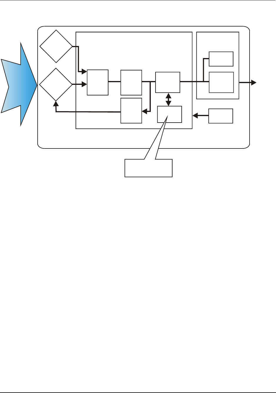
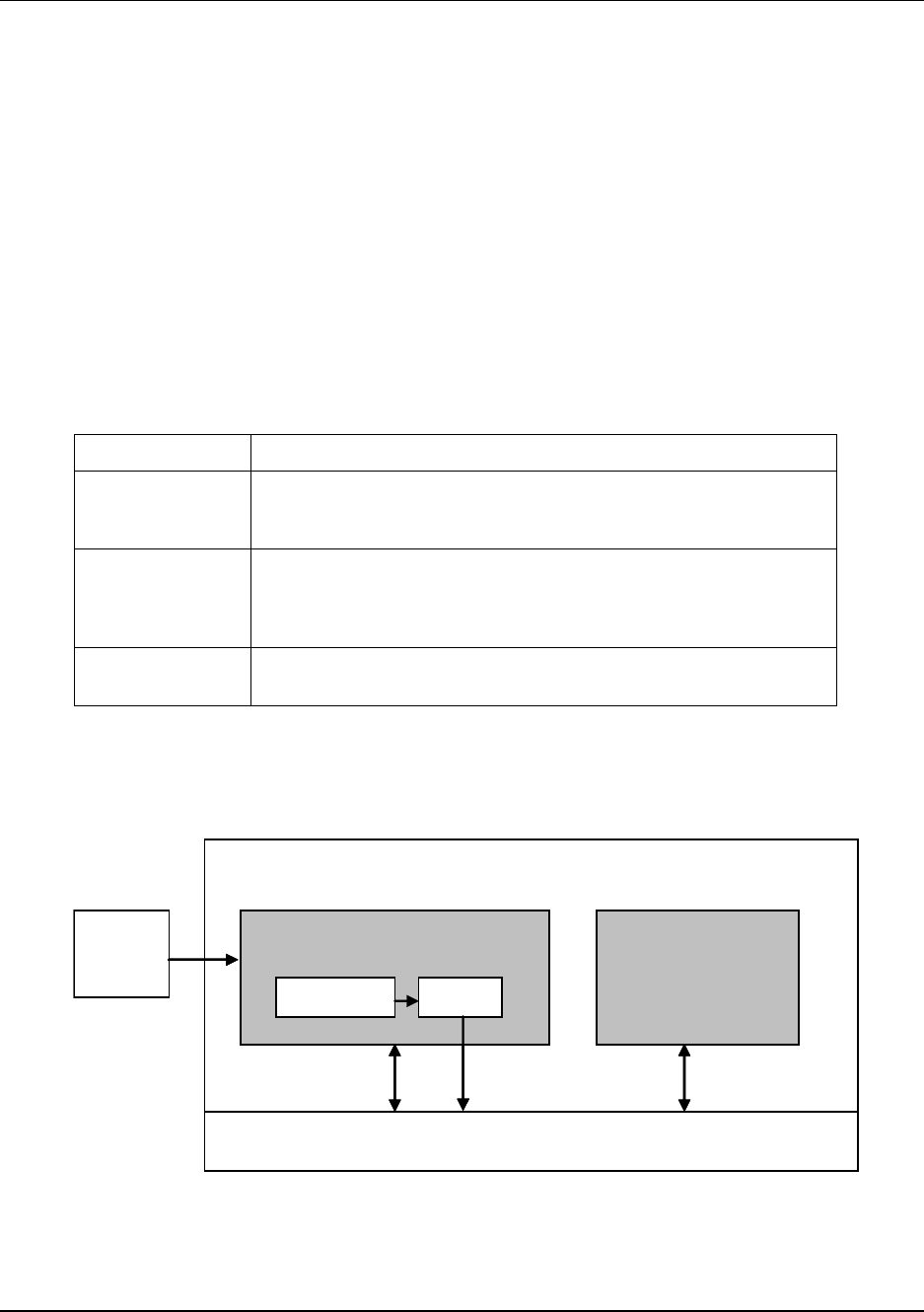
The transmitter measures the process corrosion and transmits a digital output signal proportional to the
measured variable. Its major components are an electronics housing as shown in Figure 1.
The XYR 6000 transmits its output in a digital OneWireless protocol format for direct digital
communications with systems.
The Process Variable (PV) is available for monitoring and alarm purposes.
The sample time can be configured to calculate the corrosion variables every 30 seconds, or every 1, 2, 3,
4, 5 minutes. This parameter is independent of the publish rate, which has a configuration time of 30
seconds. If the sample time and publish rate are both set to 30 seconds, the corrosion transmitter will
continuously calculate corrosion measurements and publish a new measurement (all four variables) at each
publish rate interval (every 30 seconds). This configuration will result in minimal battery life but provides
almost real time corrosion information. If the sample time is set for five minutes, all four corrosion
variables will be calculated and published within the next 30 second publish rate interval, however the
transmitter corrosion measurement will then go to sleep for 4.5 minutes, until it is time to start the next
sample. This configuration will result in maximum battery life and is the default configuration.
Figure 1 shows a block diagram of the XYR 6000 SmartCET Corrosion transmitter’s operating functions.
1. Introduction
1.4. About the transmitter
2 OneWireless XYR 6000 SmartCET Corrosion Transmitter User's Manual Revision 3
6/24/08
EEPROM
A/D
Corrosion
current
Multi-
plexer
Electronics Housing
Radio
Board
Input
from
probe
Micro-
processor
Micro-
processor
EEPROM
Battery
Antenn
a
Measurement
Board
Configuration
Data
Corrosion
potential
D/A
Figure 1 XYR 6000 SmartCET Functional Diagram

2. Specifications
2.1. European Union Usage
Revision 3 OneWireless XYR 6000 SmartCET Corrosion Transmitter User's Manual 3
6/24/08
2. Specifications
2.1 European Union Usage
This product may be used in any of the following European Union nations.
Country ISO 3166
2 letter code Country ISO 3166
2 letter code
Austria AT Latvia LV
Belgium BE Liechtenstein LI
Bulgaria BG Lithuania LT
Cyprus CY Malta MT
Czech Republic CZ Netherlands NL
Denmark DK Norway NO
Estonia EE Poland PL
Finland FI Portugal PT
France FR Romania RO
Germany DE Slovakia SK
Greece GR Slovenia SI
Hungary HU Spain ES
Iceland IS Sweden SE
Ireland IE Switzerland CH
Italy IT United Kingdom BG
2. Specifications
2.2. Certifications and approvals
4 OneWireless XYR 6000 SmartCET Corrosion Transmitter User's Manual Revision 3
6/24/08
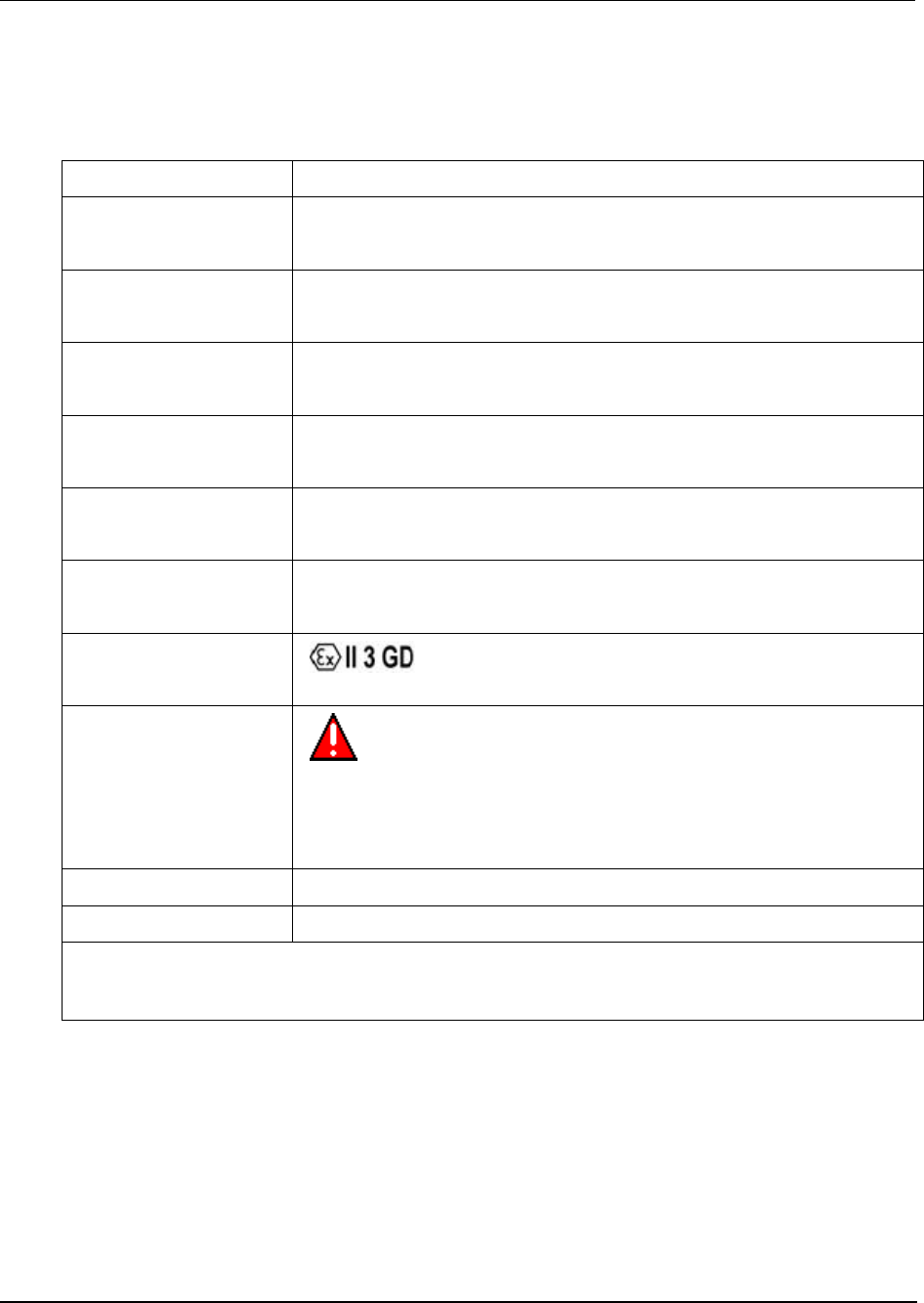
2.2 Certifications and approvals
Transmitter
See the product label for applicable approvals and ratings.
Approval / Item Ratings / Description
CSAcus Intrinsically Safe CL I, Div 1, Groups A, B, C, & D; CL II, Div 1, Groups E, F & G; CL III, T4
CL I, Zone 0: Ex ia IIC, T4; CL I, Zone 0: AEx ia IIC, T4
CSAcus Explosionproof CL I, Div 1, Groups A, B, C, & D; CL II, Div 1, Groups E, F & G; CL III, T4
CL I, Zone 1: Ex d IIC, T4; CL I, Zone 1: AEx d IIC, T4
CSAcus Nonincendive CL I, Div 2, Groups A, B, C & D; CL II, Div 2, Groups F & G; CL III, Div 2, T4
CL I, Zone 2: Ex nA IIC, T4; CL I, Zone 2: AEx nA IIC, T4
FM Approvals
Intrinsically Safe
CL I, Div 1, Groups A, B, C, & D; CL II, Div 1, Groups E, F & G; CL III, T4
CL I, Zone 0: AEx ia IIC, T4
FM Approvals
Explosionproof
CL I, Div 1, Groups A, B, C, & D; CL II, Div 1, Groups E, F & G; CL III, T4
CL I, Zone 1: AEx d IIC, T4
FM Approvals
Nonincendive
CL I, Div 2, Groups A, B, C & D; CL II, Div 2, Groups F & G; CL III, Div 2, T4
CL I, Zone 2: AEx nA IIC, T4
HON – ATEX
Non-Sparking
, Ex nA IIC, T4; Ta = 85°C, Zone 2
Process Connections in
Division 2 / Zone 2
Division 2 / Zone 2 apparatus may only be connected to processes classified
as non-hazardous or Division 2 / Zone 2. Connection to hazardous
(flammable or ignition capable) Division 1 / Zone 0, or 1 process is not
permitted.
Enclosure Type Type 4X, IP 66/67
CRN Canadian Registration Number
Class II and III installations and for Type 4X/IP66 applications require that all cable and unused entires be
sealed with an NRTL listed cable gland or seal fitting. Cable glands and seal fittings are not supplied by
Honeywell.
For detailed transmitter specifications see the following Specification and Model Selection Guide.
• XYR 6000 SmartCET Wireless Monitoring Transmitter Corrosion (document 34-XY-03-31)

2. Specifications
2.3. Agency compliance information
Revision 3 OneWireless XYR 6000 SmartCET Corrosion Transmitter User's Manual 5
6/24/08
2.3 Agency compliance information
This section contains the Federal Communications Commission (FCC), Industry Canada (IC) and Radio
Frequency compliance statements for the OneWireless Multinode device.
ATTENTION
XYR6000 units must be professionally installed in accordance with the requirements specified in the
OneWireless XYR6000 Agency Compliance Professional Installation Guide.
FCC compliance statements
• This device complies with Part 15 of FCC Rules and Regulations. Operation is subject to the
following two conditions: (1) This device may not cause harmful interference and (2) this device must
accept any interference received, including interference that may cause undesired operation.
• This equipment has been tested and found to comply with the limits for a Class A digital device,
pursuant to Part 15 of the FCC Rules. These limits are designed to provide reasonable protection
against harmful interference in a residential installation. This equipment generates, uses, and can
radiate radiofrequency energy and, if not installed and used in accordance with these instructions, may
cause harmful interference to radio communications. Operation of this equipment in a residential area
is likely to cause harmful interference in which case the user will be required to correct the
interference at his own expense.
• Intentional or unintentional changes or modifications must not be made to the Multinode unless under
the express consent of the party responsible for compliance. Any such modifications could void the
user’s authority to operate the equipment and will void the manufacturer’s warranty.
IC compliance statements
• To reduce potential radio interference to other users, the antenna type and its gain should be so chosen
that the equivalent isotropic radiated power (EIRP) is not more than that permitted for successful
communication.
• Operation is subject to the following two conditions: (1) this device may not cause interference, and
(2) this device must accept any interference, including interference that may cause undesired operation
of the device.
• This Class A digital apparatus complies with Canadian ICES-003.
• French: Cet appareil numérique de la classe A est conforme à la norme NMB-003 du Canada.
Radio Frequency (RF) statement
To comply with FCC’s and Industry Canada’s RF exposure requirements, the following antenna
installation and device operating configurations must be satisfied.
• Remote Point-to-Multi-Point antenna(s) for this unit must be fixed and mounted on outdoor permanent
structures with a separation distance between the antenna(s) of greater than 20cm and a separation
distance of at least 20cm from all persons.
• Remote Fixed Point–to-Point antenna(s) for this unit must be fixed and mounted on outdoor
permanent structures with a separation distance between the antenna(s) of greater than 20cm and a
separation distance of at least 100cm from all persons.

2. Specifications
2.3. Agency compliance information
6 OneWireless XYR 6000 SmartCET Corrosion Transmitter User's Manual Revision 3
6/24/08
• Furthermore, when using integral antenna(s) the Multinode unit must not be co-located with any other
antenna or transmitter device and have a separation distance of at least 20cm from all persons.
European Union restriction
France restricts outdoor use to 10mW (10dBm) EIRP in the frequency range of 2,454-2,483.5 MHz.
Installations in France must limit EIRP to 10dBm, for operating modes utilizing frequencies in the range of
2,454 – 2,483.5MHz.

2. Specifications
2.4. Honeywell European (CE) Declaration of Conformity (DoC)
Revision 3 OneWireless XYR 6000 SmartCET Corrosion Transmitter User's Manual 7
6/24/08
2.4 Honeywell European (CE) Declaration of Conformity (DoC)
This section contains the European Declaration of Conformity (DoC) statement, for the OneWireless product line.
R&TTE
Directive 1999/5/EC LVD
Directive 73/23/EEC EMC
Directive 2004/108/EC ATEX
Directive 94/9/EC
Harmonized Standards
Emissions Specification and Method: EN 300 328 V1.7.1
Emissions Spec and Method: EN 301 893 V1.4.1
Immunity Specification: EN 301 489-17 V1.2.1
Immunity Method: EN 301 489-1 V1.6.1
Product Standard: IEC61326-1 (1st Edition, 2002-02, Industrial Locations)
EN 50014:1992, "Electrical Apparatus for Potentially Explosive Atmospheres –
General Requirements"
EN 50021:1999, "Electrical Apparatus for Potentially Explosive Atmospheres –
Type of Protection "n"
Manufacturer’s Name and
Address
Honeywell Process Solutions
2500 West Union Hills Drive, Phoenix, AZ 85027, USA
Compliance Statement The product herewith complies with the harmonized standards listed
above. Typical product line systems and configurations have been tested,
for compliance.

2. Specifications
2.4. Honeywell European (CE) Declaration of Conformity (DoC)
8 OneWireless XYR 6000 SmartCET Corrosion Transmitter User's Manual Revision 3
6/24/08
European Declaration of Conformity statements
Language Statement
Česky
(Czech): Honeywell tímto prohlašuje, že tento Multinode je ve shodě se
základními požadavky a dalšími příslušnými ustanoveními směrnice
1999/5/ES.
Dansk
(Danish):
Undertegnede Honeywell erklærer herved, at følgende udstyr
Multinode overholder de væsentlige krav og øvrige relevante krav i
direktiv 1999/5/EF.
Deutsch
(German):
Hiermit erklärt Honeywell, dass sich das Gerät Multinode in
Übereinstimmung mit den grundlegenden Anforderungen und den
übrigen einschlägigen Bestimmungen der Richtlinie 1999/5/EG
befindet.
Eesti
(Estonian):
Käesolevaga kinnitab Honeywell seadme Multinode vastavust
direktiivi 1999/5/EÜ põhinõuetele ja nimetatud direktiivist tulenevatele
teistele asjakohastele sätetele.
English Hereby, Honeywell, declares that this Multinode is in compliance with
the essential requirements and other relevant provisions of Directive
1999/5/EC.
Español
(Spanish):
Por medio de la presente Honeywell declara que el Multinode cumple
con los requisitos esenciales y cualesquiera otras disposiciones
aplicables o exigibles de la Directiva 1999/5/CE.
Ελληνική
(Greek):
ΜΕ ΤΗΝ ΠΑΡΟΥΣΑ Honeywell ∆ΗΛΩΝΕΙ ΟΤΙ Multinode
ΣΥΜΜΟΡΦΩΝΕΤΑΙ ΠΡΟΣ ΤΙΣ ΟΥΣΙΩ∆ΕΙΣ ΑΠΑΙΤΗΣΕΙΣ ΚΑΙ ΤΙΣ
ΛΟΙΠΕΣ ΣΧΕΤΙΚΕΣ ∆ΙΑΤΑΞΕΙΣ ΤΗΣ Ο∆ΗΓΙΑΣ 1999/5/ΕΚ.
Français
(French):
Par la présente Honeywell déclare que l'appareil Multinode est
conforme aux exigences essentielles et aux autres dispositions
pertinentes de la directive 1999/5/CE.
Italiano
(Italian):
Con la presente Honeywell dichiara che questo Multinode è conforme
ai requisiti essenziali ed alle altre disposizioni pertinenti stabilite dalla
direttiva 1999/5/CE.
Latviski
(Latvian):
Ar šo Honeywell deklarē, ka Multinode atbilst Direktīvas 1999/5/EK
būtiskajām prasībām un citiem ar to saistītajiem noteikumiem.
Lietuvių
(Lithuanian):
Šiuo Honeywell deklaruoja, kad šis Multinode atitinka esminius
reikalavimus ir kitas 1999/5/EB Direktyvos nuostatas.
Nederlands
(Dutch):
Hierbij verklaart Honeywell dat het toestel Multinode in
overeenstemming is met de essentiële eisen en de andere relevante
bepalingen van richtlijn 1999/5/EG.
Malti
(Maltese):
Hawnhekk, Honeywell, jiddikjara li dan Multinode jikkonforma mal-
ħtiġijiet essenzjali u ma provvedimenti oħrajn relevanti li hemm fid-
Dirrettiva 1999/5/EC.
Magyar
(Hungarian):
Alulírott, Honeywell nyilatkozom, hogy a Multinode megfelel a
vonatkozó alapvetõ követelményeknek és az 1999/5/EC irányelv egyéb
elõírásainak.
Polski
(Polish):
Niniejszym Honeywell oświadcza, że Multinode jest zgodny z
zasadniczymi wymogami oraz pozostałymi stosownymi

2. Specifications
2.4. Honeywell European (CE) Declaration of Conformity (DoC)
Revision 3 OneWireless XYR 6000 SmartCET Corrosion Transmitter User's Manual 9
6/24/08
Language Statement
postanowieniami Dyrektywy 1999/5/EC.
Português
(Portuguese): Honeywell declara que este Multinode está conforme com os
requisitos essenciais e outras disposições da Directiva 1999/5/CE.
Slovensko
(Slovenian): Honeywell izjavlja, da je ta Multinode v skladu z bistvenimi zahtevami
in ostalimi relevantnimi določili direktive 1999/5/ES.
Slovensky
(Slovak): Honeywell týmto vyhlasuje, že Multinode spĺňa základné požiadavky a
všetky príslušné ustanovenia Smernice 1999/5/ES.
Suomi
(Finnish): Honeywell vakuuttaa täten että Multinode tyyppinen laite on direktiivin
1999/5/EY oleellisten vaatimusten ja sitä koskevien direktiivin muiden
ehtojen mukainen.
Svenska
(Swedish):
Härmed intygar Honeywell att denna Multinode står I
överensstämmelse med de väsentliga egenskapskrav och övriga
relevanta bestämmelser som framgår av direktiv 1999/5/EG.
Íslenska
(Icelandic):
Hér með lýsir Honeywell yfir því að Multinode er í samræmi við
grunnkröfur og aðrar kröfur, sem gerðar eru í tilskipun 1999/5/EC.
Norsk
(Norwegian): Honeywell erklærer herved at utstyret Multinode er i samsvar med de
grunnleggende krav og øvrige relevante krav i direktiv 1999/5/EF.
For more information about the R&TTE Directive
The following website contains additional information about the Radio and Telecommunications Terminal
Equipment (R&TTE) directive:
http://ec.europa.eu/enterprise/rtte/faq.htm

2. Specifications
2.5. Probes
10 OneWireless XYR 6000 SmartCET Corrosion Transmitter User's Manual Revision 3
6/24/08
Authentication Device
Install the Authentication Device application on any PDA having
• Windows Mobile version 4.2+
• infrared port.
2.5 Probes
Electrode area
Three finger electrodes = 4.75 cm2
Nine interleaved electrodes = 0.32 cm2
Three flush disks = 0.40 cm2
Constants for common probe materials
UNS
Number Material Atomic Mass
(grams) Density
(grams/cm3)
Number of electrons
lost on oxidation
(typical)
A91100 Aluminum 1100 27.20 2.71 3
A92024 Aluminum 2024 28.97 2.77 3
A95083 5083 Al 27.38 2.66 3
C11000 CDA 110ETP 99.9 Cu 63.54 8.89 2
C12200 DHP Cu 63.53 8.89 2
C27000 Yellow Brass 64.32 8.47 2
C44300 CDA443 (ARS AD. Brass) 64.22 8.52 2
C68700 CDA687 (Al Brass) 63.23 8.33 2
C70600 90-10 Cu-Ni [CDA 706 (Cu/Ni 90/10)] 62.95 8.94 2
C71500 CDA 715 (Cu/Ni 70/30) 61.99 8.94 2
G10100 1010 Carbon Steel 55.77 7.87 2
G10180 1018 Carbon Steel 55.75 7.86 2
G10200 1020 Carbon Steel 55.74 7.86 2
G10800 1080 Carbon Steel 55.46 7.84 2
G41400 4140 55.62 7.85 2
K01200 A179 55.77 7.87 2
K01201 A192 55.70 7.86 2
K02598 ASTM A36 55.71 7.86 2
K02700 A516-70 (A516 Gr70) 55.62 7.86 2

2. Specifications
2.5. Probes
Revision 3 OneWireless XYR 6000 SmartCET Corrosion Transmitter User's Manual 11
6/24/08
UNS
Number Material Atomic Mass
(grams) Density
(grams/cm3)
Number of electrons
lost on oxidation
(typical)
K03005 ASTM A53 [Grade B Carbon Steel] 55.68 7.86 2
K03006 A106, Grade B 55.66 7.86 2
K03006 API 5L-X52 55.71 7.86 2
K03006 API 5L-X70 55.71 7.86 2
L13601 60 Sn / 40 Pb 153.97 8.42 3
N04400 Monel 400 59.62 8.80 2
N08020 Carpenter 20 Cb3 57.30 8.08 2
N10276 C-276 [Hastelloy] 63.43 8.89 2
R50400 Titanium GR2 47.79 4.52 4
R60702 Zr 702 95.08 6.10 4
S30400 AISI 304 55.04 7.94 2
S30403 AISI 304L 55.08 7.94 2
S31600 AISI 316 56.19 7.98 2
S31603 AISI 316L 56.22 7.98 2
S41003 Duracorr 55.12 7.70 2
S41425 Mod. 13Cr 56.13 7.70 2
K03005 A53 Grade B Carbon Steel Pipe 55.68142 7.87 2
K02598 ASTM A36 55.71 7.86 2
K03006 A106, Grade B 55.66 7.86 2

3. Preparation
3.1. Installation
12 OneWireless XYR 6000 SmartCET Corrosion Transmitter User's Manual Revision 3
6/24/08
3. Preparation
3.1 Installation
Refer to the XYR 6000 Transmitter Quick Start Guide (document 34-XY-25-21) for installation, mounting
and wiring of your XYR 6000 SmartCET transmitter.
3.2 Configuration
The XYR 6000 SmartCET Transmitter contains the electronics interface compatible for connecting to the
OneWireless network. An operator uses the Wireless Builder application to configure blocks, to change
operating parameters, and to create linkages between blocks that make up the transmitter’s configuration.
These changes are written to the transmitter when it is authenticated by a security key.
3.3 Connecting to network
Use Authentication Device to connect your transmitter to the OneWireless network. See page 28.
3.4 Calibrating the transmitter
Overview
The transmitter is calibrated at the factory. User calibration is unlikely to improve calibration and is not
recommended.
However, calibration is available if desired. For all calibration methods, Wireless Builder must first be
used to prepare the channel for calibration. For access to all calibration methods, refer to Wireless Builder.
Calibration choices:
• User calibration
• Restore to factory calibration
• Linear Polarization Resistance check

3. Preparation
3.4. Calibrating the transmitter
Revision 3 OneWireless XYR 6000 SmartCET Corrosion Transmitter User's Manual 13
6/24/08
User calibration
This function calibrates the channel to the default low and high range values for the channel’s input type.
Table 1 User calibration
Step Action
1 In Wireless Builder, set the transmitter’s Write Lock to UNLOCKED.
2 In Wireless Builder, set the transmitter’s channel to OOS (Out of Service).
3 Loosen the M3 locking set screw on the transmitter’s battery end-cap (opposite end from
display). Unscrew and remove the end cap.
4 Disconnect the probe wiring from terminals 1-3. Connect a jumper between TB1-1 and TB1-2.
5 At the transmitter display, verify it is OUT SVC (out of service).
Use Authentication Device’s Device Local Configuration buttons to navigate to the transmitter’s
CAL menu.
If the transmitter is locked a LOCKED message will be displayed. Go to step 1.
If CAL menu is passcode protected, enter the passcode.
If the channel is not out of service a WRONG MODE message will be displayed. Go to step 2.
6 Select USER CAL. Follow displayed instructions.
• When display says APLY L R apply a low resistance between TB1-2 and TB1-3, such as 10
ohms.
• Use the arrow keys to enter the resistance value on the display.
• Press Enter to accept the value. Display will say WAIT 60 S (wait 60 seconds).
• When display says APLY H R apply a high resistance between TB1-2 and TB1-3, such as
10k ohms.
• Use the arrow keys to enter the resistance value on the display.
• Apply the high calibration input value indicated on display.
• Press Enter to accept the value. Display will say WAIT 60 S, then SUCCESS. Otherwise, the
display will show one of the calibration error messages listed in Table 2.
• Press Enter to return to PV display.
7 Reverse steps 3 and 4.
8 When ready, in Wireless Builder return the transmitter’s channel to service and set Write Lock
to LOCKED.

3. Preparation
3.4. Calibrating the transmitter
14 OneWireless XYR 6000 SmartCET Corrosion Transmitter User's Manual Revision 3
6/24/08
Table 2 Calibration error messages
Message Meaning
CALIBRATION_FAIL 1. Calibration gain is greater than 5%.
2. Calibration offset is greater than 5% of
sensor span.
BAD_USER_CALIBRATION CAL_SOURCE is user and user
calibration constants contain invalid
values.
BAD_FACTORY_CALIBRATION 1. CAL_SOURCE is factory and factory
calibration constants do not contain valid
values.
2. CAL_RESTORE command was issued
but factory calibration constants do not
contain valid values.
BAD_SENSOR Sensor is bad or faulty input
thermocouple.
BAD_UNITS Units in CAL UNITS parameter are
invalid or not supported by the sensor
type.
Linear polarization resistance check
Use this mode to check if a known applied resistance is correctly detected. The displayed value should
agree with the applied resistance, this indicates the transmitter (and probe wiring if included) are working
correctly. If the general corrosion value still differs from what was expected, check the probe (and probe
wiring if not in line with the test resistor) and corrosion parameter configuration.

3. Preparation
3.4. Calibrating the transmitter
Revision 3 OneWireless XYR 6000 SmartCET Corrosion Transmitter User's Manual 15
6/24/08
Table 3 Linear polarization resistance check
Step Action
1 In Wireless Builder, set the transmitter’s Write Lock to Unlocked.
2 In Wireless Builder, set the transmitter’s channel to OOS (Out of Service).
3 Loosen the M3 locking set screw on the transmitter’s battery end-cap (opposite end from
display). Unscrew and remove the end cap.
4 Disconnect the probe wiring from terminals 1-3. Connect a known resistance value (10 – 10k
ohms) between TB1-2 and TB1-3. Connect a jumper between TB1-1 and TB1-2.
5 At the transmitter display, verify it is OUT SVC (out of service).
Use Authentication Device’s Device Local Configuration buttons to navigate to the transmitter’s
CAL menu.
If the transmitter is locked a LOCKED message will be displayed. Go to step 1.
If CAL menu is passcode protected, enter the passcode.
If the channel is not out of service a WRONG MODE message will be displayed. Go to step 2.
6 • Select LPR CHK. Press Enter to accept the applied resistance. Display will say WAIT 60 S
(wait 60 seconds).
• After waiting 60 seconds the display should show the applied resistance value. This confirms
proper operation. If the displayed resistance value is correct, check Wireless Builder for
correct probe values. See page 10.
• Press Enter to return to PV display.
7 Reverse steps 3 and 4.
8 When ready, in Wireless Builder return the transmitter’s channel to service and set Write Lock
to Locked.

3. Preparation
3.4. Calibrating the transmitter
16 OneWireless XYR 6000 SmartCET Corrosion Transmitter User's Manual Revision 3
6/24/08
Restore calibration to factory default
Table 4 Restore calibration
Step Action
1 In Wireless Builder, set transmitter’s Write Lock to Unlocked.
2 In Wireless Builder, set the transmitter’s channel to OOS (Out of Service).
3 Use Authentication Device’s Device Local Configuration buttons to navigate to the transmitter’s
CAL menu.
If the transmitter is locked a LOCKED message will be displayed. Go to step 1.
If CAL menu is passcode protected, enter the passcode.
If the channel is not out of service a WRONG MODE message will be displayed. Go to step 2.
4 • Select CAL RSTR by scrolling through menu.
• Press Enter to continue.
• Display will say SUCCESS.
• If calibration is unsuccessful an error message is displayed. See Table 2.
• Press Enter to return to PV display.
5 Exit the menu.
6 When ready, in Wireless Builder return the transmitter’s channel to service and set Write Lock
to Locked.
4. Function blocks
4.1. Introduction
Revision 3 OneWireless XYR 6000 SmartCET Corrosion Transmitter User's Manual 17
6/24/08
4. Function blocks
4.1 Introduction
This section explains the construction and contents of the XYR 6000 SmartCET Corrosion Transmitter
Function Blocks.
4.2 Block description
Block types
Blocks are the key elements that make up the transmitter’s configuration. The blocks contain data (block
objects and parameters) which define the application, such as the inputs and outputs, signal processing and
connections to other applications. The XYR 6000 SmartCET Transmitter contains the following block
types.
Block Type Function
Device Contains parameters related to the overall field device rather than a
specific input or output channel within it. A field device has exactly one
device block.
AITB Contains parameters related to a specific process input or output
channel in a measurement or actuation device. An AITB defines a
measurement sensor channel for an analog process variable
represented by a floating-point value. There is one AITB per sensor.
Radio Contains parameters related to radio communication between the
transmitter and the multimode(s).
Block diagram
Figure 2 shows the blocks of the XYR 6000 SmartCET Transmitter.
Sensor Analog Input Transducer Block
(AITB)
Transmitter
Device Block
Communication Stack
Algorithm OUT
Read/
Write Publish Read/
Write
Sensor Analog Input Transducer Block
(AITB)
Transmitter
Device Block
Communication Stack
Algorithm OUT
Read/
Write Publish Read/
Write
Figure 2 Block Diagram
Each of these blocks contains parameters that are standard OneWireless-transmitter defined parameters.
The AITB and device blocks contain standard parameters common to all XYR 6000 transmitter models

4. Function blocks
4.3. Parameter details
18 OneWireless XYR 6000 SmartCET Corrosion Transmitter User's Manual Revision 3
6/24/08
(that is, pressure, temperature, DI, HLAI) as well as corrosion-specific parameters. The radio block
contains parameters for communication with the wireless network.
4.3 Parameter details
The transmitter displays a few basic parameters, such as tag, serial number, device revision, build, device
address, WFN ID.
For more information on parameters, refer to the following documents.
• OneWireless Wireless Builder User’s Guide
• OneWireless Builder Parameter Reference

5. Operation
5.1. Overview
Revision 3 OneWireless XYR 6000 SmartCET Corrosion Transmitter User's Manual 19
6/24/08
5. Operation
5.1 Overview
Display modes
The transmitter has the following display modes.
• Test. Appears briefly after power-up to self-test the display.
• Connection status. Appears when transmitter is not fully connected to the OneWireless network. See
section 5.2.
• PV display. Default mode of the transmitter displays the PV values and any status messages. See
below.
• Quick view of transmitter identification parameters. Displays read-only parameters then returns to PV
display. See page 25.
• Menu. See page 26.
Authentication Device
To navigate the transmitter displays and menus, hold the Authentication Device no more than 6” from the
transmitter and aim the infrared beam at the transmitter display while tapping the Device Local
Configuration buttons (Table 9). You can also use the PDA’s buttons.
Authentication Device menus are described in section 5.6 starting on page 27.

5. Operation
5.2. Transmitter connection status
20 OneWireless XYR 6000 SmartCET Corrosion Transmitter User's Manual Revision 3
6/24/08
5.2 Transmitter connection status
Table 5 Transmitter connection status
Displayed
status Definition What to do
NO KEY Transmitter needs a key from the
Authentication Device and is not transmitting.
Transmit a key to the transmitter. See page
28.
NOT CONN Transmitter is in between discovery attempts. If Transmitter does not make a connection
within five minutes, do the following:
• Check that Key is correct for the network
you are trying to join.
• Check that Multinode(s) in the local area
are turned on and are already a secure
part of the network.
• Check if KeyServer is active.
• Check the KeyServer Event Log to see if
the Transmitter is actively trying to join.
Errors in the Event Log show that the
Transmitter is trying to join but that there
are problems. Consult the OneWireless
Wireless Builder documentation for
troubleshooting errors.
DISCOVER Transmitter has not made a connection to a
Multinode and is in discovery (searching for a
connection to a Multinode). Transmitter will
automatically enter a power saving mode if it
cannot make a connection and will retry later.
Wait for connection. If Transmitter does not
make a connection within five minutes, see
NOT CONN in this table.
SECURING Transmitter has connected with the network
and is validating its key.
Wait for connection. If Transmitter does not
make a connection within five minutes, see
NOT CONN in this table.
CONNECTD For units with radio firmware build* 53 or
higher:
Transmitter has validated the key and has
made a secure connection with at least two
Multinodes. Transmitter should appear in
Wireless Builder as an uncommissioned
device.
For units with radio firmware build* 52:
Transmitter has validated the key and has
made a secure connection with at least one
Multinode. Transmitter should appear in
Wireless Builder as an uncommissioned
device.
For units with radio firmware build* 53 or
higher: No action required.
For units with radio firmware build* 52:
Transmitter will periodically look for a
second Multinode in order to form a
redundant connection to the network. If
connected with only one Multinode Wireless
Builder will display a Secondary Multinode
Address of 0.
NO REDUN Appears only on units with radio firmware
build* 53 or higher. No redundancy, that is,
Transmitter has connected with only one
Multinode.
No action required. The Transmitter will
periodically look for a second Multinode in
order to form a redundant connection to the
network
*Use the PDA to determine your radio firmware build number (page 21).

5. Operation
5.3. Transmitter PV display
Revision 3 OneWireless XYR 6000 SmartCET Corrosion Transmitter User's Manual 21
6/24/08
5.3 Transmitter PV display
In the PV display, the following information is displayed sequentially. For detailed descriptions of the
PV’s, see page 39.
Item displayed Example Details
PV1 value 1 +80.0 The General Corrosion Rate is the average or
general corrosion rate. Range: 0 – 250 mil/year
(0 - 6.35 mm/yr.)
PV1 engineering units mPY Mils per year (mPY) or millimeters per year
(mmPY).
PV1 status BAD See Table 6. If no PV status is displayed (blank)
then the PV value is good.
Device status LOW BATT See Table 7. If no device status is displayed
(blank) then the device status is normal.
If two or more device status messages are in
effect they are displayed alternating with the PV
values.
PV2 value 2 +0.50 Pitting Factor (also referred to as localized
corrosion indicator). Range: 0 – 1. Unitless.
PV2 status UNC See Table 6. If PV status is not displayed then
the PV value is good.
PV3 value 3 +26.50 B value, also known as the Stern-Geary
constant. Range: 0 to 200 typical.
PV3 units mV Millivolts per decade
PV3 status OUT SVC See Table 6. If PV status is not displayed then
the PV value is good.
PV4 value 4 +404.0 Corrosion monitoring index. Unitless. Normal
range is 0 – 2000.
PV4 status See Table 6. If PV status is not displayed then
the PV value is good.

5. Operation
5.3. Transmitter PV display
22 OneWireless XYR 6000 SmartCET Corrosion Transmitter User's Manual Revision 3
6/24/08
Table 6 PV status
PV status Cause - Action
(blank) • PV is normal – no action required
BAD • Possible calibration error – Clear calibration
• AITB can not execute due to internal firmware state – Attempt cold restart of
device.
• AITB can not execute due to hardware fault – Replace sensor board
• Sensor failure – Check input connections
• Sensor failure – Check bad probe
UNC • Warning: Input inaccurate due to uncertain input data integrity.
• Warning: Input inaccurate due to input conversion limitations or resolution.
• Warning: Input outside of characterized range. Value is estimated.
Table 7 Device status
Transmitter
display Wireless Builder display Definition What to do
OUT SVC OOS All channels are out of
service.
Restore mode to Auto in Wireless
Builder.
CAL ERR Calibration Error Calibration Data Invalid
or could not be read.
Use Cal Clear, Restore, or User
Calibrate.
CFG ERR Configuration Error Configuration Check
Error.
Database is corrupted. Cold start
and reload configuration.
LOW BAT Low Battery Battery Voltage Critically
Low
Replace batteries as soon as
possible. See page 47.
NO RADIO Radio Interprocessor
Comm Error
Radio Board is not
accessible.
Restart both the radio and sensor.
If condition persists, replace
sensor module. See page 45.
BAD RADIO
SPI
Sensor Radio SPI
Communication Failure
Radio detected loss of
communication with
sensor board over the
inter-processor
communication link.
Restart both the radio and sensor.
If condition persists, replace
sensor module. See page 45.
BAD RADIO
EEPROM
EEPROM SPI
Communication Failure
Radio EEPROM SPI
Communication failure
The radio will not be able to
perform firmware upgrades but will
operate normally using installed
code. Replace sensor module.
See page 45.
RADIO WDT
RESET
WDT Reset Occurred Radio Watch Dog
Timeout detected
Restart both the radio and sensor.
If condition persists, replace
sensor module. See page 45.

5. Operation
5.3. Transmitter PV display
Revision 3 OneWireless XYR 6000 SmartCET Corrosion Transmitter User's Manual 23
6/24/08
Transmitter
display Wireless Builder display Definition What to do
BAD RADIO Radio Circuitry Failure Radio circuitry has failed The radio processor detected error
on internal radio circuitry. Replace
sensor module. See page 45.
The following status messages have multiple meanings. Refer to Wireless Builder Device Status for exact cause.
E FAIL A/D Failure Diagnostics detected
defect with Analog to
Digital Converter.
Replace sensor module. See page
45.
E FAIL Electronics Failure Electronic Failure
detected on Sensor
Board. Could be caused
by one of the status
items marked by *.
Restart both the radio and sensor.
If condition persists, replace
sensor module. See page 45.
E FAIL* NVM Fault* Startup diagnostics
detected defect in
Sensor Non-Volatile
Memory
Replace sensor module. See page
45.
E FAIL* Program Memory Fault* Startup diagnostics
detected defect in
Sensor Read Only
Memory
Replace sensor module. See page
45.
E FAIL* RAM Fault* Startup diagnostics
detected defect in
Processor Random
Access Memory
Replace sensor module. See page
45.
INP FAIL Input Failure Input Error Check input connection. If
condition persists, replace the
probe.
INP FAIL A/D Failure Diagnostics detected
defect with Analog to
Digital Converter.
Replace sensor module. See page
45.
The following statuses are displayed only in Wireless Builder Device Status.
Blank Electrode Short Circuit An input is shorted Check probe electrodes for
conductive films or defective
(shorted) cable.
Check transmitter probe cable
connections for a possible short at
the transmitter input terminals.
Blank Electrode Open Circuit or
LPR Mode Error
Input open or probe not
in solution
Check probe cable for a loose or
defective (open) connection to the
electrodes or transmitter terminals.
Blank Harmonic Distortion
Mode Not Possible
No valid 3rd harmonic
component to calculate B
value PV
Corrosion rate may be very low or
system may be under diffusion
control.
Blank Asymmetric Response
From Probe
Electrochemical
response of probe is not
symmetrical
Check electrodes for differential
attack on electrodes, for example,
crevice on one electrode.

5. Operation
5.3. Transmitter PV display
24 OneWireless XYR 6000 SmartCET Corrosion Transmitter User's Manual Revision 3
6/24/08
Transmitter
display Wireless Builder display Definition What to do
Blank DAC Voltage Deviation Electrode driver voltage
deviation > 3% of
measured voltage
Check electrodes for conductive
films.
Check transmitter probe cable
connections for a possible short at
the transmitter input terminals.
Check transmitter operation offline
with a different probe to determine
if the fault is caused by the probe
or transmitter.
Blank Calibration Cleared
User calibration cleared
to factory constants
User calibration has been cleared
and reset to the factory values.
Proceed with user calibration if
utilizing probe cables >12 ft and if
the anticipated corrosion rate is
>200 mpy.
blank* Device/Firmware
Mismatch*
Sensor Board Firmware
Error. The software did
not pass verification
tests.
Replace sensor module. See page
45.
blank* Heap Memory Not
Available*
Heap Allocation Failure.
Software detected heap
shortage and some
communication packets
may have been dropped.
Clear by warm restart of device. If
condition persists contact
Honeywell service.
blank* Watchdog Timer Error* Sensor Watchdog
Timeout. The processor
was restarted due to
unexpected operation.
Clear by warm restart of device. If
condition persists contact
Honeywell service.

5. Operation
5.4. Transmitter quick view of parameters
Revision 3 OneWireless XYR 6000 SmartCET Corrosion Transmitter User's Manual 25
6/24/08
5.4 Transmitter quick view of parameters
If you press the up or down arrow key during the PV display, the following quick view parameters are
shown sequentially, then the PV display resumes.
Parameter Description
Transmitter type HONEYWELL XYR 6000 CORROSION
Tag The name given to this transmitter
Serial number Transmitter serial number. This is the
WBSN on the transmitter’s nameplate.
Do not confuse this with the other
nameplate item marked “Serial.”
Device revision This parameter changes whenever
objects and parameters are added,
deleted, or the data type or range
changes. It does not change if the
application firmware changes without
affecting the device description.
Build Sensor firmware number

5. Operation
5.5. Transmitter menu
26 OneWireless XYR 6000 SmartCET Corrosion Transmitter User's Manual Revision 3
6/24/08
5.5 Transmitter menu
Menu tree
At the PV display, press Enter to access the menus. To interact with the menus use the Device Local
Configuration onscreen buttons (page 30) or the buttons on your PDA.
Table 8 Menu tree
Menu item Description
CAL Calibration menu. May be password-protected. See Table 9 on page 30 for
password number entry.
USER CAL Lets you set calibrate to custom low and high range values. See page 12.
CAL RSTR Restores calibration to factory setting. The factory setting is very accurate
and should be adequate for most applications. See page 12.
LPR CHK Linear Polarization Resistance check. Use this to check a known applied
resistance. The displayed value should agree with the applied resistance; if
not then a problem exists in the probe or in the corrosion parameters. See
page 12.
RADIO Radio menu
PRI RSSI Primary receive signal strength. Read only. Signal strength 00 is too weak to
connect to the network.
Displayed Value Value dBm Rx Margin dB
00 < -86 < 10
01 -86 to -81 10 to 15
02 -80 to -75 16 to 21
03 -74 to -69 22 to 27
04 -68 to -63 28 to 33
05 -62 to -57 34 to 39
06 -56 to -51 40 to 45
07 -50 to -45 46 to 51
08 -44 to -11 52 to 85
09 ≥ -10 Saturation
SEC RSSI Secondary receive signal strength. Same as PRI RSSI. Read only.
WFN ID Wireless Field Network ID. Read only.
DEV ADD Device address. Read only.
TX POWER Radio transmit power. Read only.
5. Operation
5.6. Authentication device menus
Revision 3 OneWireless XYR 6000 SmartCET Corrosion Transmitter User's Manual 27
6/24/08
5.6 Authentication device menus
Overview
Hold the Authentication Device no more than 6” from the transmitter and aim the infrared beam at the
transmitter display while tapping on the screen command or button.
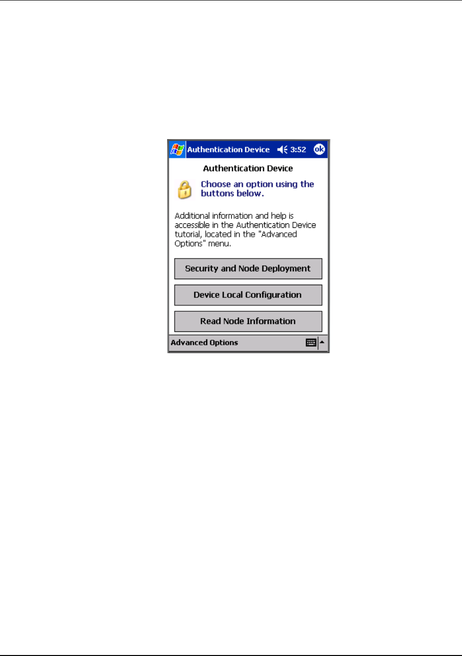
Main menu
The main menu is shown below. Details start on the next page.
Figure 3 Main menu
5. Operation
5.6. Authentication device menus
28 OneWireless XYR 6000 SmartCET Corrosion Transmitter User's Manual Revision 3
6/24/08
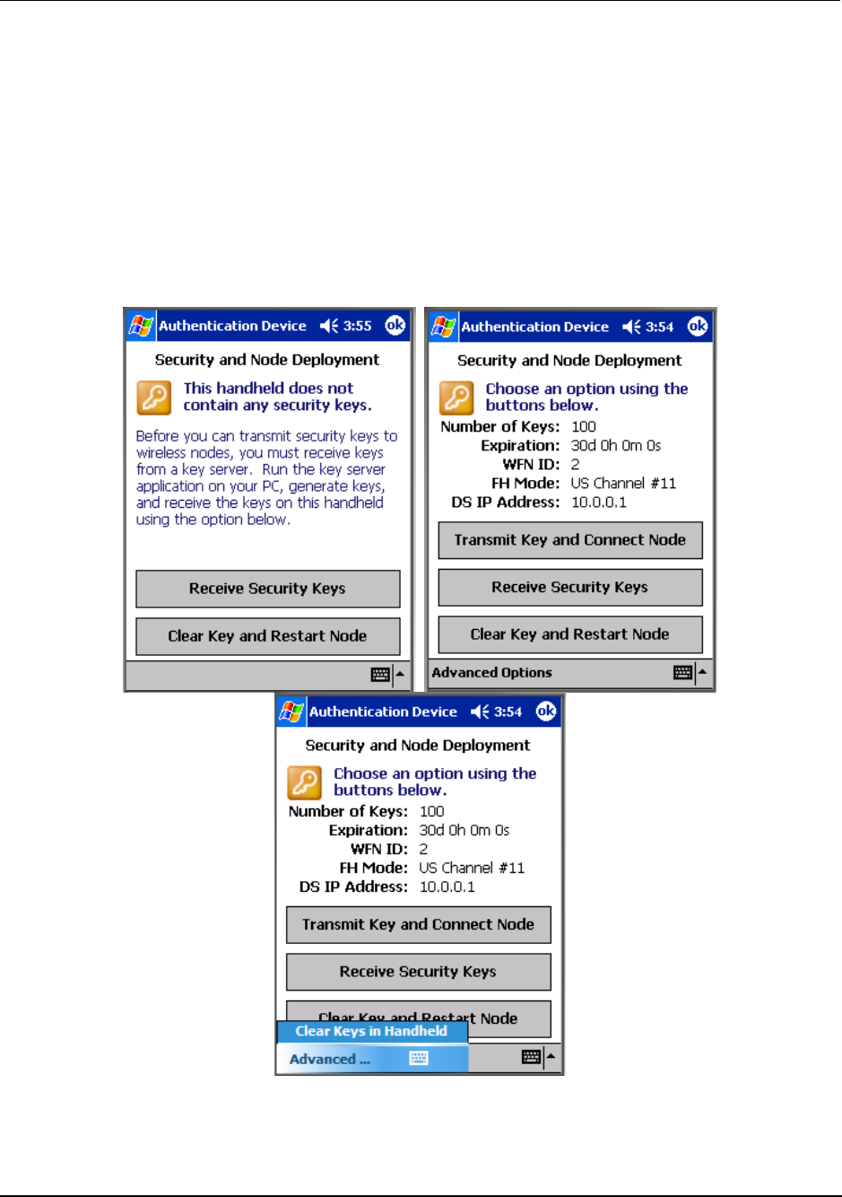
Security and Node Deployment
Use this to receive and transmit security keys for connecting the transmitter to the OneWireless network.
Use this to:
• receive new security keys,
• transmit security keys for connecting the transmitter (or other nodes) to the OneWireless network,
• clear all security keys from the PDA,
• clear the transmitter’s key and reset its configuration to factory default (such as for decommissioning).
Figure 4 Security and Node Deployment

5. Operation
5.6. Authentication device menus
Revision 3 OneWireless XYR 6000 SmartCET Corrosion Transmitter User's Manual 29
6/24/08
To connect your transmitter to the OneWireless network perform the following steps.
Step Action
1 If the PDA contains no keys, obtain new security keys from the PC
application Key Server Manager.
To do this, select Receive Security Keys. Keys can be received either
through Infrared (by aiming PDA at the infrared dongle) or through an
ActiveSync/USB connection. See Key Server Communication Method
under Advanced options on page 33 for details.
Important: The Comm Method settings must match in the PC’s Key Server
Manager and in the Authentication Device (both must be set to Infrared or
both to ActiveSync) in order for your PDA to receive security keys. See Key
Server Communication Method under Advanced options on page 33 for
details.
2 When the Authentication Device has valid unexpired keys, aim it at the
transmitter and transmit a key to the transmitter. The transmitter will validate
the key and then use it to make a connection to the OneWireless Network.
The Transmitter may continue to show the diagnostic message “NO KEY” for
a brief time while it validates the key before showing the “DISCOVER”
message.
To verify your transmitter has been authenticated, see the Connection prompt
on the Read Node Info screen (page 31).
To decommission your transmitter from the OneWireless network, select Clear Key and Restart Node.
This clears the transmitter’s key, network and security configurations, and resets the transmitter to its
factory default settings. perform the following steps.
Select Clear Keys from Handheld (under Advanced Options) when:
• The PDA has keys from one system, but you have moved your Authentication Device to another
system, or
• you want to clear all keys so that you cannot deploy any more keys without going to the key server
manager and getting more.
For more details on keys, refer to Getting Started with Honeywell OneWireless Solutions.
5. Operation
5.6. Authentication device menus
30 OneWireless XYR 6000 SmartCET Corrosion Transmitter User's Manual Revision 3
6/24/08
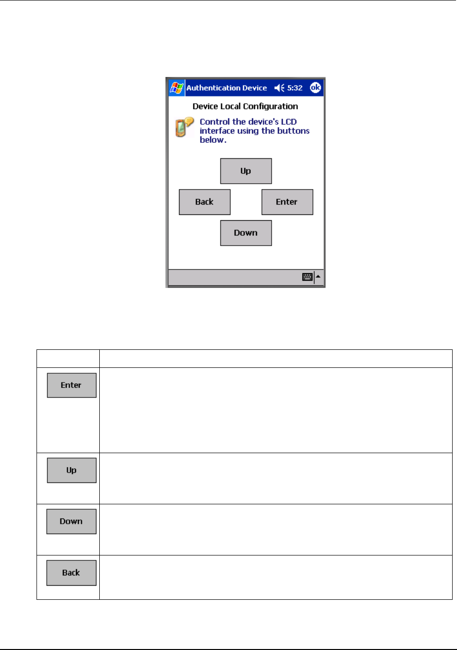
Device Local Configuration
Use Device Local Configuration buttons (Table 9) to navigate the transmitter menus (Table 8) and to make
selections and changes. You can also use the PDA buttons.
Figure 5 Device Local Configuration screen
Table 9 Buttons for Device Local Configuration
Button Function
• Enter the Menu Tree.
• Enter submenu of the menu that is appearing on the screen.
• Execute action.
• Submit the entered number while doing number entry.
• Read value of certain displayed parameters.
• Go to the next menu in the same level.
• View quick view parameters in Normal Display Sequence (PV Display).
• During number entry, increment the digit or change +/- sign.
• Go to the previous menu in the same level.
• View quick view parameters in Normal Display Sequence (PV Display).
• During number entry, decrement the digit or change +/- sign.
• Go to the upper menu level.
• When changing a number value, move cursor to the left/more significant digit, then
wrap around to the least significant digit.
5. Operation
5.6. Authentication device menus
Revision 3 OneWireless XYR 6000 SmartCET Corrosion Transmitter User's Manual 31
6/24/08
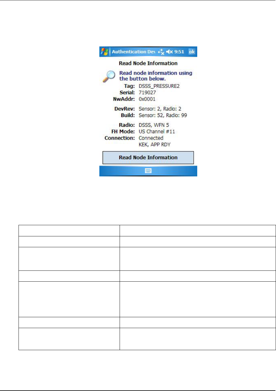
Read Node Information
Use this to read the transmitter’s information shown in Figure 6. Similar to quick view parameters on the
transmitter display. (See page 25.)
Figure 6 Read Node Information
Table 10 Read Node Information
Item Description
Tag The name given to this transmitter
Serial Transmitter serial number. This is the WBSN on the
transmitter’s nameplate. Do not confuse this with the other
nameplate item marked “Serial.”
NwAddr Network Address of the device in hexadecimal.
DevRev Device Revision. This parameter changes whenever objects
and parameters are added, deleted, or their data type or range
changes. It does not change if the application firmware
changes without affecting the device description. Range: 0 to
65535.
Build Sensor firmware and radio firmware build numbers.
Radio Hardware radio type, FHSS or DSSS
WFN ID: Wireless Field Network ID. Range: 0 to 255.

5. Operation
5.6. Authentication device menus
32 OneWireless XYR 6000 SmartCET Corrosion Transmitter User's Manual Revision 3
6/24/08
Item Description
FH Mode Frequency group or frequency channel selection used by the
wireless network of the device. The value must match the
value set in the gateway and interface nodes to allow
communication between the device and the wireless network.
Modes:
US Channel #1
US Channel #6
US Channel #11
US Guard Bands
EU Channel #1
EU Channel #7
EU Channel #13
EU Guard Bands
US/EU Spec Div A
US/EU Spec Div B
US/EU Channel #3
US/EU Channel #10
Complete Spectrum
Connection The first line displays one of the following connection states.
No Security Key – No security key has been deployed to the
device or multinode. The user must give a security key to
the device or multinode before it will join the wireless sensor
network.
No Connection – A security key exists in the device or
multinode, but no connection has been formed. The device
or multinode is waiting to form a connection and will
automatically retry shortly. Users may transmit a new
security key in order to force the device or multinode to
immediately retry to form a connection.
Discovering – The device is attempting to form a connection
to the wireless sensor network. The device is discovering
multinodes and, if a multinode is found, will transition to the
securing state.
Securing – The device is attempting to form a connection to
the wireless sensor network. The device has discovered
one or two multinodes and is attempting to form a secure
session. If successful, the device will transition to the
connected state.
Connected – A secure connection is formed with one or two
multinodes.
The second line contains detailed state information useful for
problem reporting.
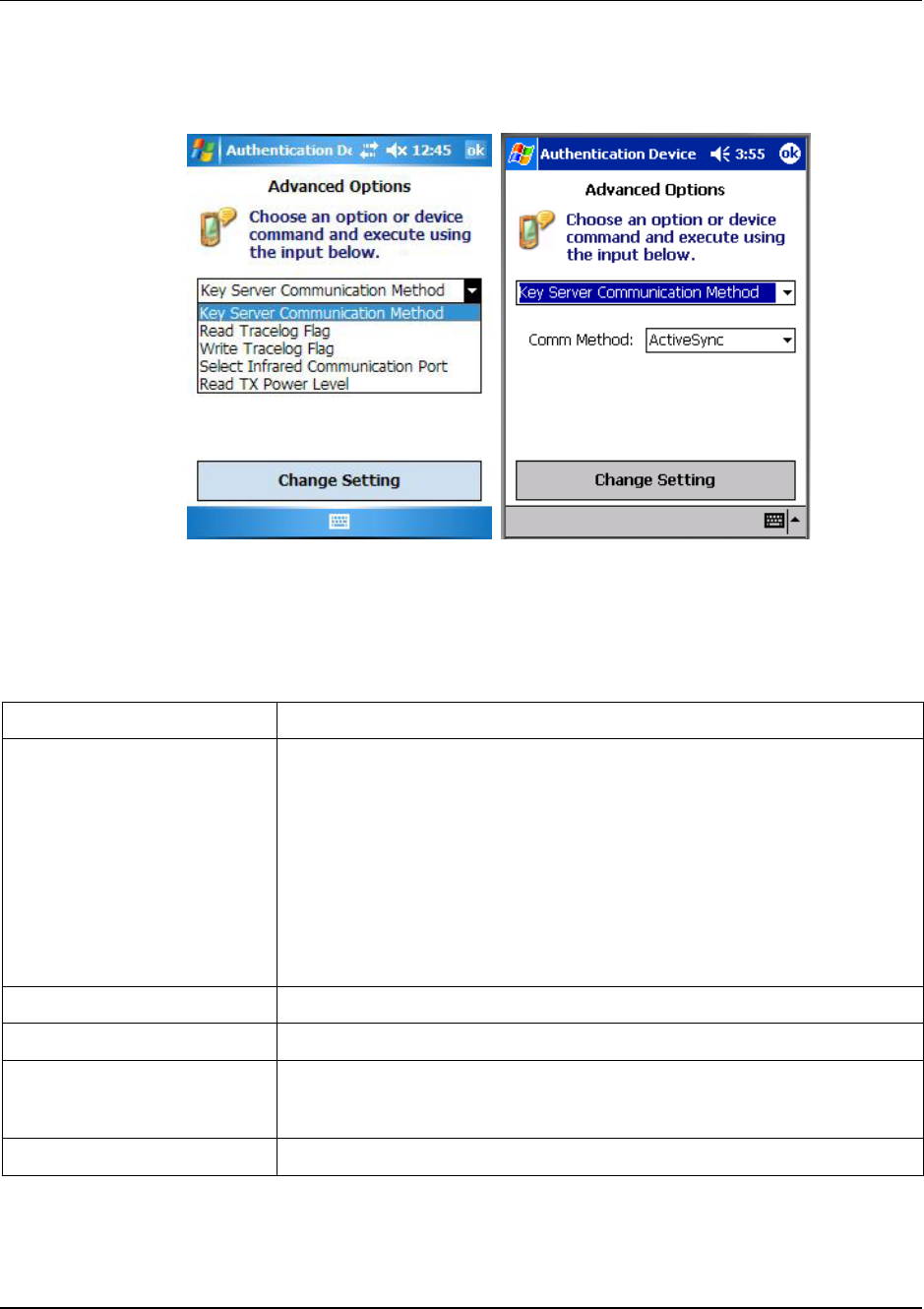
5. Operation
5.6. Authentication device menus
Revision 3 OneWireless XYR 6000 SmartCET Corrosion Transmitter User's Manual 33
6/24/08
Advanced Options
Advanced options are non-typical configuration commands.
Figure 7 Advanced Options
Table 11 Advanced Options
Item Description
Key Server Communication
Method
Determines how the PDA will receive security keys from the PC’s Key Server
Manager application. From the Comm Method menu select one of the
following methods.
ActiveSync – Select this to receive keys over a USB connection, such as
while the PDA battery is being charged in its base.
Infrared – Select this to receive keys over the infrared port.
Important: The Comm Method settings match in the PC’s Key Server
Manager and in the Authentication Device (both must be set to Infrared or both
to ActiveSync) in order for your PDA to receive security keys.
Restart Commands the transmitter to restart with the current configuration.
Write Tracelog Flag Reads the transmission power level of the transmitter radio.
Select Infrared Communication
Port
Overrides the detected infrared communication port detected on your PDA. If
infrared communication is not functioning, you can override the detected
settings using this option.
Read TX Power Level Reads the transmission power level of the transmitter radio.

6. Troubleshooting
6.1. Diagnosis of Transmitter Health from Measurement Data
34 OneWireless XYR 6000 SmartCET Corrosion Transmitter User's Manual Revision 3
6/24/08
6. Troubleshooting
6.1 Diagnosis of Transmitter Health from Measurement Data
The output from the corrosion transmitter can provide insight into the health of the transmitter operation.
Table 12 shows the output expected for each variable when the transmitter is operating properly and the
table also shows an indication when a probe short condition exists and when no probe is connected.
Table 12 Diagnosis of Transmitter Health
Description Transmitter
output
variable
General
Corrosion Pitting /
Localized
Corrosion
Probe short No probe
connected
Corrosion rate PV Across range Across range Maximum
value
Note 1.
~ 0
Note 3.
Pitting Factor SV <0.1 >0.1 <0.001 ~ 1
B value TV (Stable)
Note 2.
(Unstable)
Note 2.
(Unstable)
Note 2.
(Unstable)
Note 2.
Corrosion
Monitoring
Index
QV Across the
range
Across the
range
(~ 0)
Note 2.
~ 0
Note 1: Corrosion rate maximum will depend on the material constants and surface area entered. From a
measurement perspective, it relates to the absolute value of the polarization resistance of the working
electrode. If the polarization resistance is very low (<10 ohms), the instrument will be close to current
saturation. For optimal operation it is preferable to maintain the polarization resistance of the working
electrode at values of >100 ohms. This may be achieved to some extent by changes to the surface area
of the working electrode, thereby optimizing the span of the corrosion measurement.
Note 2: Items shown in brackets are general statements. No specific value can be provided.
Note 3: An exact zero value will not be achieved. It will be almost zero or very small, for example, 0.001
mpy.
Under conditions when general corrosion is prevalent on the material being monitored, the measured
corrosion rate observed as the primary variable (PV) may be expected to show evidence of being stationary
for a short term. In these cases the corrosion rate will tend to exhibit only slight variation in the short term,
perhaps over periods of hours or longer. Any slight process change, such as temperature variability is
often reflected in the corrosion rate behavior. Larger excursions in the corrosion rate may be experienced
if there are more pronounced changes to the environment, for example due to flow rates or changes in
composition.
The secondary variable, Pitting Factor, will typically exhibit a low value under these conditions (for
example, <0.01), although it may exhibit some short term response to abrupt changes in the environment,
for example sudden changes in temperature, flow rate or fluid composition.
The tertiary variable (the B value) will usually fall in a range of 0.010 to 0.030 volts, and will be stable.
The quaternary variable (Corrosion Mechanism Indicator) is largely dependant on the type of material
being studied, but generally, if active corrosion is being observed (>5mpy), it will tend to be significantly
larger than the case for very low corrosion rates.

6. Troubleshooting
6.2. General troubleshooting procedures
Revision 3 OneWireless XYR 6000 SmartCET Corrosion Transmitter User's Manual 35
6/24/08
If low general corrosion rates are being observed, which are close to instrument baseline (< 0.05 mpy), the
Pitting Factor may appear artificially high (for example, > 0.01).
When localized corrosion is occurring, the observed general corrosion rate values may be in the range 0.1
to 10 mpy or higher, depending on the material and the environment. The Pitting Factor will tend to
exhibit higher magnitude peaks of activity during pit initiation events, whereas propagating pits may be
associated with a general increase in the observed corrosion rate and lower levels of Pitting Factor (<0.1).
The general corrosion rate in the case of propagating pits often exhibits short term variation and is
noticeably less stable than the case for general corrosion. Pitting is often accompanied by increased
variability in the B value. With increasing degrees of pit propagation, the CMI values will also tend to
increase.
6.2 General troubleshooting procedures
The XYR 6000 SmartCET transmitter is designed to operate over a broad range of corrosion rates.
However, most problems associated with the corrosion rate calculation arise when the actual corrosion rate
is extremely high, and there is likelihood that the instrument is approaching or exceeding its stated
operating limits. In some circumstances, this can be remedied by using sensors with a smaller surface
area.
Another factor to be considered is severe diffusion limiting or mass transport control of the corrosion
processes. In this case the B value determination may become difficult, and erratic behavior with very
high values may be observed. Troubleshooting procedures that deal with this condition and general
situations are shown in Table 13.
Table 13 Troubleshooting procedures
Symptom Possible cause Action
Corrosion rate values are very
low and do not change
1. Probe or probe cable fault –
bad connection to probe
electrodes
2. Transmitter fault
1. Check continuity with test cell
connected at probe end of
cable. May be necessary to
remove probe and carry out
continuity checks between
connecting pins and probe
sensing elements.
2. Check with test cell
connected directly to transmitter
terminals.
Consult with the factory for
additional information.

6. Troubleshooting
6.2. General troubleshooting procedures
36 OneWireless XYR 6000 SmartCET Corrosion Transmitter User's Manual Revision 3
6/24/08
Symptom Possible cause Action
Corrosion rates are very high,
Pitting Factor very low, and B
values are very low.
This problem could be due to a
shorting condition between
probe sensing elements
1a. Disconnect probe and the
corrosion rate should fall.
1b. Remove probe and
physically check for electrode to
electrode contact.
1c. May be caused by the
presence of conductive
corrosion deposits for example,
iron sulfide (B value very low).
2. Use probe with smaller
surface area.
Corrosion rate switches
abruptly from high to very low
levels, Pitting Factor is very
high, and the B value goes to
the current default value.
This situation is symptomatic of
when the (internal) polarization
resistance calculation has
apparently gone to a negative
value, with the result that the
corrosion rate is indeterminate
and a default low value is
returned. Apparent negative
polarization resistances may
occur in situations where the
corrosion rates are very high
and the electrode area is
incorrect for the process
situation.
The electrodes could be too
large. Investigate using
electrodes with a smaller area.
Another possible cause may be
due to an asymmetrical
response of the electrodes, for
example due to crevice
corrosion occurring on one of
the electrodes. The electrodes
should be inspected in this
case.
All the variables (corrosion rate,
Pitting Factor, B value and CMI)
are suspect and could be in
error. Consult with the factory
for additional information.
All corrosion variables are very
unstable exhibiting one or more
of the following:
Corrosion rate unstable, may
drop to very low values
Pitting Factor low when
corrosion rate high and vice
versa.
B values unstable switching
between -20 and 100.
CMI unstable switching from
very low value 0, to large value
for example, > 5000.
These symptoms are typically
caused by high and variable
corrosion rates in the process
environment, hard diffusion
limiting processes, and/or
electrode surface areas being
too large for the application.
Disconnect probe. Corrosion
values should return to baseline
levels.
Check with test cell, transmitter
should give a standard
response.
Electrode surface area could be
incorrect for the application.
Contact a Honeywell corrosion
specialist to review the
application.
Corroding systems with real
diffusion / mass transport
limiting scenarios are
problematic monitoring
situations.

6. Troubleshooting
6.3. Recommended operating conditions
Revision 3 OneWireless XYR 6000 SmartCET Corrosion Transmitter User's Manual 37
6/24/08
Symptom Possible cause Action
Inaccurate readings. Possible wrong parameter
values for the probe’s electrode
area.
Check the following parameter
values in Wireless Builder.
• Electrode area
• Atomic mass
• Density
• Electrons
See page 10 for probe
parameters.
6.3 Recommended operating conditions
The XYR 6000 SmartCET transmitter utilizes electrochemical techniques that are applicable to a wide
range of corrosive conditions. The following table provides the applicable operating envelope for XYR
6000 SmartCET with additional comments when the operating range is outside envelope.
Table 14 Recommended operating conditions
Measurement Range Comments
Corrosion rate 0-250 mpy dependent upon the
electrode surface area, typically
in range of 1 to 10 cm2. (Default
URV setting is 100 mpy and the
electrode area is 4.75 cm2.)
Higher sensitivity at low
corrosion rates may be
achieved by using larger
electrodes - consult factory for
additional information.
The higher corrosion rate range
is achieved with appropriately
sized electrodes (for example,
small areas). If symptoms
listed in Table 13 occur, the B
value should be fully reviewed
and analyzed before providing
a corrosion rate estimate. It is
recommended to qualify the
rate estimate against mass loss
from electrodes – consult
factory for additional
information.
Pitting Factor 0.001 to 1. With low corrosion rates, the
Pitting Factor may appear
artificially high due to very low
observed general corrosion
rates – consult factory for
additional information.
B value Expected range: 5 to 60mV
(0.005 to 0.06V).
Low values may be due to
formation of surface films
having redox behavior (for
example, Iron sulfide). The
electrode essentially starts to
become non-polarizable.

6. Troubleshooting
6.3. Recommended operating conditions
38 OneWireless XYR 6000 SmartCET Corrosion Transmitter User's Manual Revision 3
6/24/08
Measurement Range Comments
High values predominantly may
be due to diffusion limiting
processes. As the
electrochemical processes
become more diffusion limiting,
the B value may not achieve a
stable value. Applying the B
value from this type of situation
(for example, updating the
default value) is not
recommended. Consult with
the factory for additional
information.
Corrosion Mechanism Indicator Expected range: 0 to 2000. Values are dependent on
material and environment.

7. Corrosion measurements
7.1. Overview
Revision 3 OneWireless XYR 6000 SmartCET Corrosion Transmitter User's Manual 39
6/24/08
7. Corrosion measurements
7.1 Overview
The XYR 6000 SmartCET corrosion transmitter outputs four corrosion measurements.
• General Corrosion Rate - average or general corrosion rate, and is generally expressed in mils per year
(mpy) or millimeters per year (mmpy).
• Pitting Factor - dimensionless number that indicates the presence of a pitting (localization) corrosion
environment.
• B value - expressed in millivolts per decade, and is commonly also known as the Stern Geary constant.
• Corrosion Mechanism Indicator – indicator representing health of the probe in regard to fouling or
wear.
The values are all updated every 30 seconds, which is the total measurement cycle time of the instrument.
The values for the General Corrosion Rate, the Pitting Factor and the Corrosion Mechanism Indicator are
set to output the most recent values.
7.2 General corrosion rate
The Linear Polarization Resistance (LPR) technique is used to calculate the General Corrosion Rate. This
calculation is usually the prime variable of interest since it reflects the overall rate of metallic corrosion.
Corrosion may be directly related to operational parameters such as temperatures, flow, chemical
composition, etc.
The XYR 6000 SmartCET uses three electrodes that are referred to as the working, counter and reference
electrodes. A low frequency sinusoidal voltage excitation is applied to the working electrode with respect
to the reference electrode, and the current is measured and analyzed (on the counter electrode)
synchronously with the applied signal.
Given a sinusoidal pattern, the working electrode becomes positively charged and then negatively charged
(in other words, polarized positively and negatively). It is a DC voltage applied in a sinusoidal pattern and
resembles an AC pattern. The peak-to-peak value of the sinusoidal wave is 50mV.
Strictly, this is a measurement of the real part of the low frequency impedance of the working electrode.
This method of analysis is selected due to its superior noise rejection, which is particularly useful when
studying corroding systems since they exhibit varying degrees of intrinsic noise. The result is equivalent to
measuring the linear polarization resistance of the working electrode. With this measurement, the corrosion
current (hence, the corrosion rate) is inversely proportional to the polarization resistance.
This measurement also employs the Stern-Geary approximation where the Stern-Geary constant (or B
value) is the proportionality constant. In practice, with no prior knowledge of the system, the “default”
value of B for this type of measurement is typically chosen to be in the range 25 to 30 mV; in reality, the
value of B is system-dependent.
Use of the default B value may result in the absolute corrosion rate being somewhat in error, but in some
instances, it is the general trend of the corrosion rate that could be of interest instead of the absolute value.
Working method summary
There are three electrodes in use, which are designated working electrode (WE), counter electrode (CE)
and reference electrode (RE). A sinusoidal DC voltage is applied on the WE (voltage is varied).

7. Corrosion measurements
7.3. B value
40 OneWireless XYR 6000 SmartCET Corrosion Transmitter User's Manual Revision 3
6/24/08
In turn, the current response is measured between the CE and WE. The ratio of voltage to current provides
the polarization resistance. The polarization resistance is not a true resistance in the traditional sense, but
can be treated as such in describing the LPR technology.
The corrosion current is inversely proportional to the polarization resistance. How does an electrical
model represent a corrosion process? What makes corrosion look like an electrical system?
Corrosion comprises an anodic process and a cathodic process, i.e. electrochemical processes that occur at
anodic and cathodic sites on the metal surface. When corrosion is occurring, there is an increase of ionic
flow between the anodic and cathodic sites (i.e. Faradaic process). A non-corrosive system would not
exhibit any ionic flow.
Table 15 shows the relationship between corrosion rate, environment characterization and the
recommendation for getting accurate General Corrosion Rate measurements.
Table 15 Corrosion Rate and Environment Characterization
Corrosion Rate Environment Comments
>200 mpy Highly conductive, highly
corrosive
This could be at upper level of XYR 6000 accuracy
range. If used in this environment, electrodes with small
area should be used (for example, 1cm2).
1-200mpy Average corrosion rate Use correct probe type according to process application.
0.01-1mpy Low conductivity or passive
system
Electrodes with large area should be used (for example,
10cm2).
<0.01mpy Extreme passivity or low
conductivity (for example,
organic medium)
This could be at lower level of XYR 6000 accuracy
range. If used in this environment, electrodes with large
area should be used (for example, 10cm2).
7.3 B value
The B value represents a correction factor ‘constant’ that is determined by the mechanism and kinetics of
the corrosion process. In a dynamic process, research has shown that the B value is not constant. For
example, the B value for a sour system with a microbiological influence on corrosion activity could be
4mV. The average “industry-accepted” default B value is typically between 25 and 30mV. Houston tap
water gives a B value of 15mV. A severely scaled system (i.e. inorganic scale deposits on the metal
surface) would show a B value of around 100 mV.
By evaluation of the non-linearities in the current response from the LPR measurement, it is possible to
determine a B value for the system being studied. This involves the analysis of the higher order harmonic
content of the current response, and computation of a value of B for the system being studied.
With knowledge of the B value it is possible to refine the LPR-generated corrosion rate estimate, since the
uncertainty regarding the standard (default) B value is removed. The B value is directly related to the
mechanistic properties of the component anodic and cathodic corrosion processes.
The anodic process is essentially the metal oxidation and the cathodic process is, for example, the oxygen
reduction or hydrogen evolution. These are essentially non-linear processes, and the current will typically
(but not always) have a logarithmic dependence on the applied voltage.
The B value is a composite of the individual anodic and cathodic Tafel slopes.
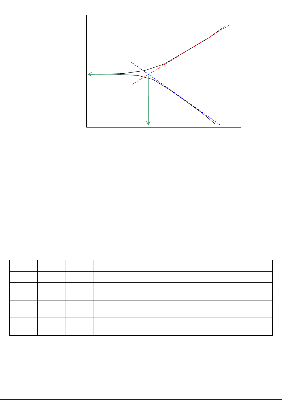
7. Corrosion measurements
7.4. Pitting factor
Revision 3 OneWireless XYR 6000 SmartCET Corrosion Transmitter User's Manual 41
6/24/08
Potential
Ecorr
ba (anodic Tafel slope)
bc (cathodic Tafel slope)
Figure 8 Individual Anodic and Cathodic Tafel Slopes
The B value is calculated using the following equation: B = ba*bc/2.303*(ba+bc)
So these individual slopes are representative of non-linear processes. In the calculation of the general
corrosion rate, the B value approximation assumes that the processes are essentially linear for a small
applied potential, for example: 10 – 20 mV away from the corrosion potential and only takes into account
the first order (linear) processes. The harmonic distortion analysis takes into account the second and third
order processes, i.e. it is similar to fitting a polynomial to x3, but we use the higher frequency harmonic
components to analyze rather than trying to fit a polynomial – it’s a much better analysis route.
XYR 6000 SmartCET uses Harmonic Distortion Analysis (HDA) to calculate the ‘true’ B value. With an
accurately computed B value, the default B value used in the LPR calculation can be changed thus
enabling a more accurate corrosion rate calculation to be made.
Table 16 Corrosion Rate based on B value, anodic and cathodic values
ba bc B Comments
60mV 60mV 13mV Both processes activation controlled (for example, sulfide film)
60mV ∞ 26mV
Anodic process activation, cathodic diffusion, controlled (for example,
aerated system)
120mV ∞ 52mV
Anodic process activation, cathodic diffusion, controlled (anodic slope
different), for example, multiphase system
∞ ∞ ∞ Severe anodic and cathodic diffusion limiting, for example, vapor
phase. B value indeterminate.
7.4 Pitting factor
The Pitting Factor is a measure of the overall stability of the corrosion process, and is obtained from a
measurement of the intrinsic current noise of the working electrode, and comparing this measurement to
the general corrosion current obtained from the LPR measurement (for example, general corrosion rate
calculation).
Log (Current density)
Lo
g
(
Icorr
)

7. Corrosion measurements
7.5. Corrosion mechanism indicator
42 OneWireless XYR 6000 SmartCET Corrosion Transmitter User's Manual Revision 3
6/24/08
General corrosion processes typically have low levels of intrinsic noise, with the ratio of noise to the
general corrosion current typically being ≤1% (Pitting Factor ≤0.01). With the onset of instability (pit
initiation), localized corrosion occurrence leads to increasingly higher levels of current noise with respect
to the general corrosion current such that the Pitting Factor may reach a value of 1. The Pitting Factor can
be viewed as the probability that the corrosion mechanism is localized.
Spontaneous changes in the environment may also cause the instantaneous value of the Pitting Factor to
approach a value of 1 in the short term; however, for localized corrosion, the Pitting Factor will remain
unstable and secondary evidence may be observed in terms of the overall stabilities of both the general
corrosion rate estimate and the B value.
XYR 6000 uses electrochemical noise (ECN) to calculate the Pitting Factor.
A useful analogy to explain the difference between general corrosion and localized corrosion (Pitting
Factor) is that of a flashlight with its beam constantly ON (general corrosion) and one that is flickering
(localized corrosion).
Table 17 Pitting Factor Values
PF Value Comments
0.1 or higher Pitting/localized corrosion – initiation (Note: check corrosion rate value; if very low, PF
could be misleading).
0.01 to 0.1 Intermediate level; general corrosion but check PF does not increase above 0.1.
0.01 or lower General corrosion.
7.5 Corrosion mechanism indicator
The metallic corroding interface is complex and dynamic. The general corrosion rate, the B value, and the
Pitting Factor all help to characterize the Faradaic corrosion processes (current flow that is the result of
electrochemical process) quite thoroughly. However, in order to be more complete in the analysis of the
electrochemical response there is at least one more factor which needs to be taken into account.
During the measurement of the low frequency impedance, a reactive, phase shifted component of the
current response may be detected. This is a consequence of the physical nature of the metal/environment
(electrolyte) interface, and may reflect mechanistic properties such as the presence of films, film formation
and surface adsorption processes.
The values obtained are likely to be characteristic of a particular system being studied. For example sulfide
filming may cause the reactance to become more positive, whereas adsorption processes may cause the
values to go negative. The absolute values obtained may provide the corrosion expert with extra
knowledge regarding the corrosion behavior of any particular system.
Understanding CMI values
The CMI is a qualitative indicator of whether a surface film is present or not. If there is no film and only
corrosion is present, the CMI will have an intermediate value. Inorganic scale, or thick passive oxide films
with little or no conductivity, will show a low CMI value.
Analysis of the Corrosion Mechanism Indicator is shown in Table 18.

7. Corrosion measurements
7.5. Corrosion mechanism indicator
Revision 3 OneWireless XYR 6000 SmartCET Corrosion Transmitter User's Manual 43
6/24/08
Table 18 CMI values
CMI Value Comments
> 2000 Possible redox film, for example, sulfide
20 - 200 Freely corroding system
0-20 Passive material, for example, Al, Zr, Ti
Negative Adsorption processes, for example, some corrosion
inhibitors

8. Maintenance/Repair
8.1. Parts
44 OneWireless XYR 6000 SmartCET Corrosion Transmitter User's Manual Revision 3
6/24/08
8. Maintenance/Repair
8.1 Parts
The following replacement parts may be ordered from Honeywell. For other replacement parts such as
probes, refer to XYR 6000 Wireless Transmitter Corrosion Specification (document 34-XY-03-31)
Part number Qty. Description
50015866-504 1 ELECTRONICS MODULE ASSEMBLY aka SENSOR MODULE for Corrosion
50015866-508 1 ELECTRONICS MODULE ASSEMBLY aka SENSOR MODULE for Corrosion-
Instrinsically Safe
50015866-512 1 ELECTRONICS MODULE ASSEMBLY aka SENSOR MODULE for Corrosion-
DSSS Intrinsically Safe
50015843-501 1 TERMINAL BOARD
50015623-501 1 CAP ASSEMBLY, BATTERY, ALUMINUM, DARK BEIGE
50016190-501 1 CAP ASSEMBLY, LCD, ALUMINUM, DARK BEIGE
50026009-501 1 CAP ASSEMBLY, BATTERY, STAINLESS STEEL
50026127-501 1 CAP ASSEMBLY, LCD, STAINLESS STEEL
50016229-501 1 ANTENNA ASSEMBLY, 2 dBi INTEGRAL RIGHT-ANGLE, ALUMINUM
50016229-502 1 ANTENNA ASSEMBLY, 2 dBi INTEGRAL RIGHT-ANGLE, STAINLESS STEEL
50020767-501 1 ANTENNA ASSEMBLY, 2 dBi INTEGRAL STRAIGHT, STAINLESS STEEL
50020767-502 1 ANTENNA ASSEMBLY, 2 dBi INTEGRAL STRAIGHT, ALUMINUM
50031714-501 1 ANTENNA ASSEMBLY, 4 dBi INTEGRAL STRAIGHT, STAINLESS STEEL
50031714-502 1 ANTENNA ASSEMBLY, 4 dBi INTEGRAL STRAIGHT, ALUMINUM
50031715-501 1 ANTENNA ASSEMBLY, 4 dBi INTEGRAL RIGHT-ANGLE, ALUMINUM
50031715-502 1 ANTENNA ASSEMBLY, 4 dBi INTEGRAL RIGHT-ANGLE, STAINLESS STEEL
50018414-001 1 REMOTE OMNI-DIRECTIONAL ANTENNA, 8 dBi
50018415-001 1 REMOTE DIRECTIONAL ANTENNA, 14 dBi
50016577-501 1 ANTENNA ADAPTER ASSEMBLY, REMOTE, TYPE TNC, STAINLESS STEEL
50016577-502 1 ANTENNA ADAPTER ASSEMBLY, REMOTE, TYPE TNC, ALUMINUM
50028364-501 1 ANTENNA ADAPTER ASSEMBLY, REMOTE, TYPE N, ALUMINUM
50028364-502 1 ANTENNA ADAPTER ASSEMBLY, REMOTE, TYPE N, STAINLESS STEEL
50018110-001 1 COAX CABLE ASSY, 1.0M ( 3.3 Ft) LONG, RP-TNC - N-MALE
50018110-002 1 COAX CABLE ASSY, 3.0M (10.0 Ft) LONG, RP-TNC - N-MALE
50018110-003 1 COAX CABLE ASSY, 10.0M (33.0 Ft) LONG, RP-TNC - N-MALE
50018278-001 1 COAX CABLE ASSY, 1.0M ( 3.3 Ft) LONG, N-MALE - N-MALE
50018278-002 1 COAX CABLE ASSY, 3.0M (10.0 Ft) LONG, N-MALE - N-MALE
50018278-003 1 COAX CABLE ASSY, 10.0M (33.0 Ft) LONG, N-MALE - N-MALE
50018279-090 1 LIGHTNING SURGE ARRESTOR
50025288-001 1 BATTERY HOLDER, PRESSURE
continued
8. Maintenance/Repair
8.2. Replacing sensor module
Revision 3 OneWireless XYR 6000 SmartCET Corrosion Transmitter User's Manual 45
6/24/08
Part number Qty. Description
50025288-002 1 BATTERY HOLDER, TEMPERATURE, HLAI, CORROSION
50026010-001 2 3.6V LITHIUM THIONYL CHLORIDE (Li-SOCI2) BATTERY
50026010-002 4 3.6V LITHIUM THIONYL CHLORIDE (Li-SOCI2) BATTERY
50026010-003 10 3.6V LITHIUM THIONYL CHLORIDE (Li-SOCI2) BATTERY
8.2 Replacing sensor module
Tools required
• #1 Phillips Screwdriver or 1/8” Slotted Screwdriver
• Torque Screwdriver
• 1.5 mm hex key
Procedure
WARNING
Risk of death or serious injury by explosion. Do not open transmitter
enclosure when an explosive gas atmosphere is present.
CAUTION
Take precautions against electrostatic discharge to prevent damaging the
sensor module.
Table 19 Sensor module replacement
Step Action
1 Honeywell recommends that the transmitter be removed from service and moved to a clean
area before servicing.
2 Loosen the M3 locking set screw on the display end-cap. See item 1 in Figure 9. Unscrew and
remove the end cap.
3 Loosen the two screws on the sensor module. See items 2 in Figure 9.
4 Disconnect each connector on the sensor module. See items 3 in Figure 9.
5 Install new sensor module. Be sure to orient sensor module in the proper viewing orientation
before tightening two sensor compartment screws.
Reverse steps 1-4.
Torque screws to 0,4 – 0,6 N-M (3.5 – 5.3 Lb-in).
Honeywell recommends lubricating the end cap O-ring with a Silcone Grease such as Dow
Corning #55 or equivalent before replacing the end cap.
Return transmitter to service.
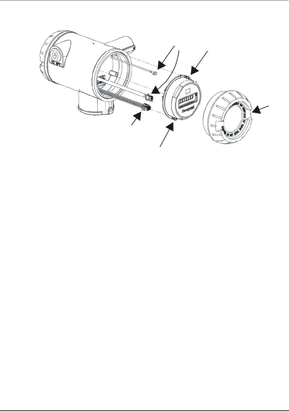
8. Maintenance/Repair
8.2. Replacing sensor module
46 OneWireless XYR 6000 SmartCET Corrosion Transmitter User's Manual Revision 3
6/24/08
1
2
2
3
3
Figure 9 Sensor module removal and replacement
8. Maintenance/Repair
8.3. Replacing batteries
Revision 3 OneWireless XYR 6000 SmartCET Corrosion Transmitter User's Manual 47
6/24/08
8.3 Replacing batteries
When to replace
When the transmitter displays a LO BATT message you have 2-4 weeks to replace both batteries before
they expire. When batteries are removed or expired, all transmitter data is retained in the transmitter’s non-
volatile memory.
Tools required
• #1 Phillips Screwdriver or 1/8” Slotted Screwdriver
• Torque Screwdriver
• 1.5 mm hex key
Procedure
ATTENTION
Batteries must be replaced only by a trained service technician.
WARNINGS
• Risk of death or serious injury by explosion. Do not open transmitter
enclosure when an explosive gas atmosphere is present.
• Batteries must not be changed in an explosive gas atmosphere.
• The batteries used in this device may present a risk of fire or chemical
burn if mistreated. Do not recharge, disassemble, heat above 100°C
(212°F), or incinerate.
Table 20 Battery replacement procedure
Step Action
ATTENTION
You must replace both batteries. Both batteries must be the same model from the same
manufacturer. Mixing old and new batteries or different manufacturers is not permitted.
Use only the following 3.6V lithium thionyl chloride (Li-SOCl2) batteries (non-rechargeable),
size D. No other batteries are approved for use in XYR 6000 Wireless Transmitters.
• Xeno Energy XL-205F
• Eagle Picher PT-2300H
• Tadiran TL-5930/s
• Honeywell p/n 50026010-001 (Two 3.6V lithium thionyl chloride batteries) (1 transmitter)
• Honeywell p/n 50026010-002 (Four 3.6V lithium thionyl chloride batteries) (2 transmitters)
• Honeywell p/n 50026010-003 (Ten 3.6V lithium thionyl chloride batteries) (5 transmitters)
1 Loosen the M3 locking set screw on the battery end-cap (opposite end from display). See item
1 in Figure 10. Unscrew and remove the end cap.
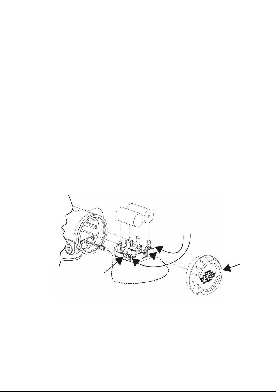
8. Maintenance/Repair
8.3. Replacing batteries
48 OneWireless XYR 6000 SmartCET Corrosion Transmitter User's Manual Revision 3
6/24/08
Step Action
2 Using thumb and forefinger, squeeze the battery connector at top and bottom to disengage the
locking mechanism, then pull to disconnect. See item 2 in Figure 10.
3 Loosen the two battery holder retaining screws (closest to the batteries). See item 3 in Figure
10. The screws are captive.
4 Pull the battery holder out of the transmitter.
5 Remove the old batteries from the battery holder. If needed, pry out the batteries by using a
slotted screwdriver as a lever in the holder’s side slots. See item 4 in Figure 10.
6 Insert the new batteries using correct polarity shown on the battery holder.
7 Insert the battery holder into the transmitter. Reattach the screws and tighten to 0,4 – 0,6 N-M
(3.5 – 5.3 Lb-in).
Re-connect battery connector.
Honeywell recommends lubricating the end cap O-ring with a Silcone Grease such as Dow
Corning #55 or equivalent before replacing the end cap.
8 Screw the end cap back on and tighten the M3 locking screw.
9 Dispose of used battery promptly per local regulations or the battery manufacturer’s
recommendations. Keep away from children. Do not disassemble and do not dispose of in fire.
1
2
+
-
+
-3
4
Figure 10 Battery replacement
8. Maintenance/Repair
8.4. Replacing antenna
Revision 3 OneWireless XYR 6000 SmartCET Corrosion Transmitter User's Manual 49
6/24/08
8.4 Replacing antenna
Tools required
• #1 Phillips Screwdriver or 1/8” Slotted Screwdriver
• Torque Screwdriver
• 1.5 mm hex key
Procedure
ATTENTION
You must replace your antenna with the same type, that is, elbow, straight, or
remote. Changing to a different antenna type is not permitted by approval
agencies.
CAUTION
Take precautions against electrostatic discharge to prevent damaging the
sensor module.
WARNING
POTENTIAL ELECTROSTATIC CHARGING HAZARD
The integrally mounted antenna shroud is made of Teflon® and has a surface
resistance greater than 1Gohm per square. When the XYR 6000 transmitter
is installed in potentially hazardous locations care should be taken not to
electrostatically charge the surface of the antenna shroud by rubbing the
surface with a cloth, or cleaning the surface with a solvent. If electrostatically
charged, discharge of the antenna shroud to a person or a tool could possibly
ignite a surrounding hazardous atmosphere.

8. Maintenance/Repair
8.4. Replacing antenna
50 OneWireless XYR 6000 SmartCET Corrosion Transmitter User's Manual Revision 3
6/24/08
Table 21 Antenna replacement procedure
Step Action
1 Honeywell recommends that the transmitter be removed from service and moved to a clean
area before servicing.
2 Loosen the M3 locking set screw on the display end-cap. See item 1 in Figure 11. Unscrew
and remove the front end cap.
3 Loosen the two screws on the sensor module. See items 2 in Figure 11.
4 Remove the sensor module from the transmitter body and disconnect the antenna connector
from CN2 connector on the sensor module. See item 3 in Figure 11.
5 Loosen the locking set screw at the antenna base. Unscrew the antenna from the transmitter.
Remove the antenna and its connector from the transmitter. See Figure 11.
6 Feed the new antenna’s connector through the antenna hole to the front of the transmitter. Do
not connect to sensor module yet. Lubricate o-ring with Silcone Grease such as Dow Corning
#55. Screw new antenna into transmitter body until finger-tight, then back off 180 degrees to
permit adjustment later.
7 Attach antenna connector to CN2 connector on sensor module. See item 3 in Figure 11.
8 Insert sensor module. Orient in the proper viewing orientation before tightening two sensor
compartment screws. See items 2 in Figure 11. Torque screws to 0,4 – 0,6 N-M (3.5 – 5.3 Lb-
in).
9 Replace the front end cap. Honeywell recommends lubricating the front end cap O-ring with a
Silcone Grease such as Dow Corning #55 or equivalent before replacing the end cap.
10 Adjust antenna for best reception. Don’t rotate antenna more than 180 degrees either direction
or you could twist and break the antenna wiring inside. Tighten the antenna locking set screw.
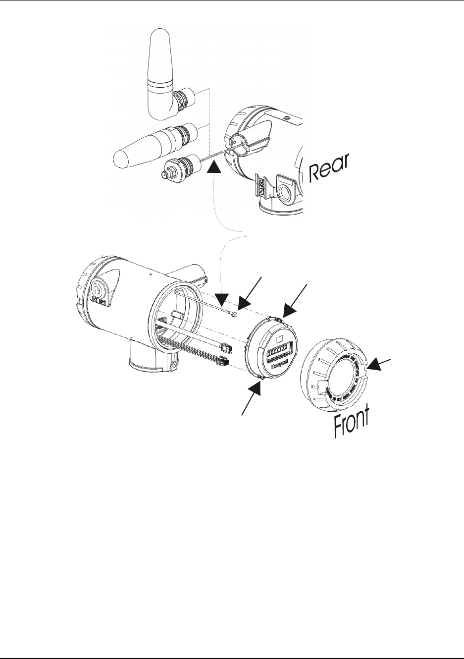
8. Maintenance/Repair
8.4. Replacing antenna
Revision 3 OneWireless XYR 6000 SmartCET Corrosion Transmitter User's Manual 51
6/24/08
Antenna connecto
r
1
2
2
3
Figure 11 Antenna replacement
8. Maintenance/Repair
8.5. Replacing terminal board
52 OneWireless XYR 6000 SmartCET Corrosion Transmitter User's Manual Revision 3
6/24/08
8.5 Replacing terminal board
When to replace
Various error messages can help you diagnose a faulty terminal board. These are described elsewhere in
this manual.
Tools required
• #1 Phillips Screwdriver or 1/8” Slotted Screwdriver
• Torque Screwdriver
• 1.5 mm hex key
Procedure
WARNING
Risk of death or serious injury by explosion. Do not open transmitter
enclosure when an explosive gas atmosphere is present.
Table 22 Terminal board replacement procedure
Step Action
1 Honeywell recommends that the transmitter be removed from service and moved to a clean
area before servicing.
SHOCK HAZARD
Depending on your installation, transmitter input wiring sources may contain high voltage.
Disconnect all power from transmitter input sources before accessing the terminal board.
Failure to do so could result in death or serious injury.
2 Loosen the M3 locking set screw on the battery end-cap (opposite end from display). See item
1 in Figure 12. Unscrew and remove the end cap.
3 Using thumb and forefinger, squeeze the battery connector at top and bottom to disengage the
locking mechanism, then pull to disconnect. See item 2 in Figure 12.
4 Loosen the two battery holder retaining screws (closest to the batteries). See item 3 in Figure
12. The screws are captive.
5 Pull the battery holder out of the transmitter.
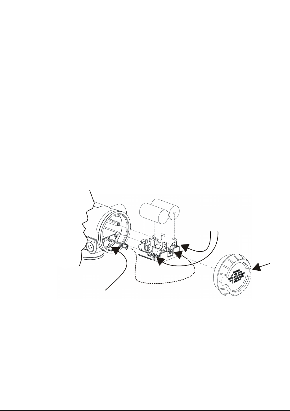
8. Maintenance/Repair
8.5. Replacing terminal board
Revision 3 OneWireless XYR 6000 SmartCET Corrosion Transmitter User's Manual 53
6/24/08
Step Action
6 Disconnect field wiring from terminal board and label it to ease reconnection.
7 Remove and save the 3 screws that attach the terminal board to the housing. Take care
because these screws are not captive. See item 4 in Figure 12.
8 Remove terminal board by disconnecting cable from back of the terminal board. Do not pull on
the wires or you could damage them. Instead, depress the latch while pulling on the connector.
9 Attach connector to new terminal board. Observe correct polarity of the connector. Verify that
the cable is latched to the terminal board.
10 Fasten terminal board with screws from step 7.
11 Re-connect field wiring.
12 Insert the battery holder into the transmitter. Reattach the screws and tighten to 0,4 – 0,6 N-M
(3.5 – 5.3 Lb-in).
Re-connect battery connector.
Honeywell recommends lubricating the end cap O-ring with a Silicone Grease such as Dow
Corning #55 or equivalent before replacing the end cap.
13 Screw the end cap back on and tighten the M3 locking screw.
1
2
3
4
Figure 12 Terminal board replacement

8. Maintenance/Repair
8.5. Replacing terminal board
Revision 3 OneWireless XYR 6000 SmartCET Corrosion Transmitter User's Manual 55
6/24/08

8. Maintenance/Repair
8.5. Replacing terminal board
56 OneWireless XYR 6000 SmartCET Corrosion Transmitter User's Manual Revision 3
6/24/08