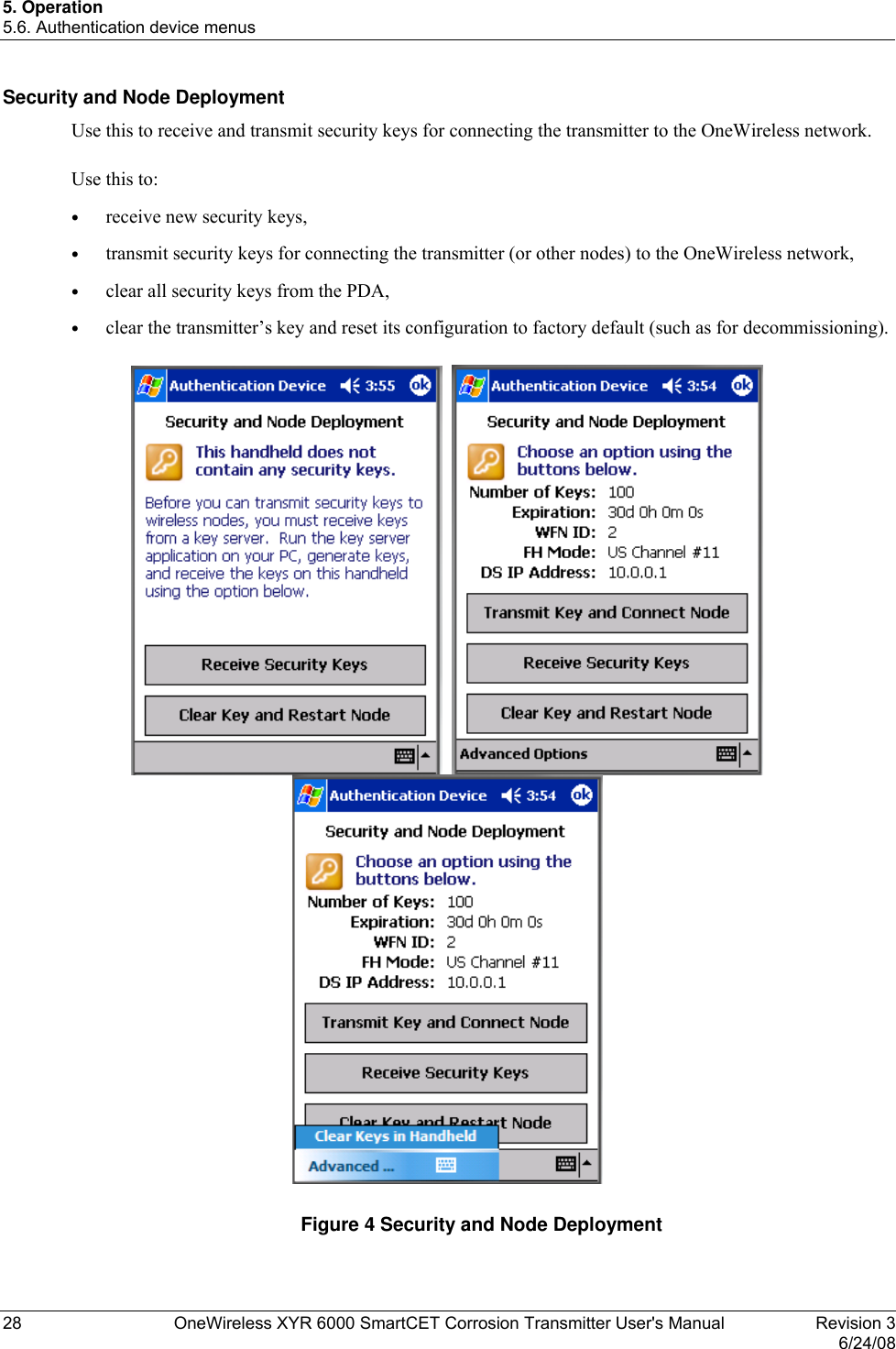
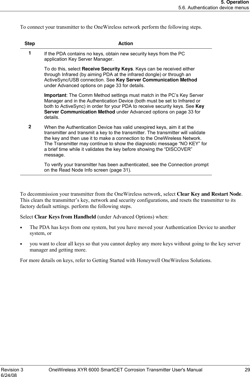
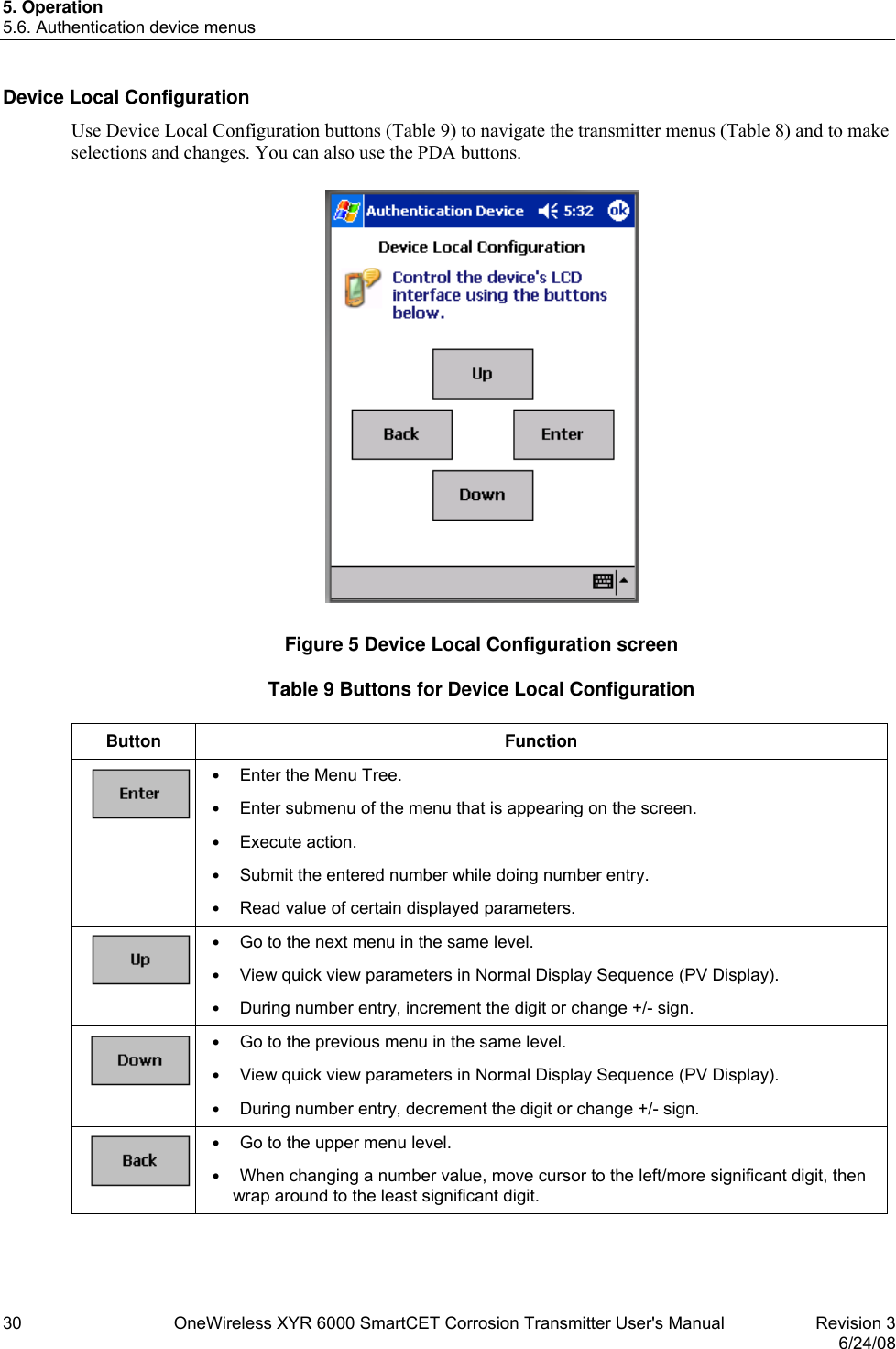
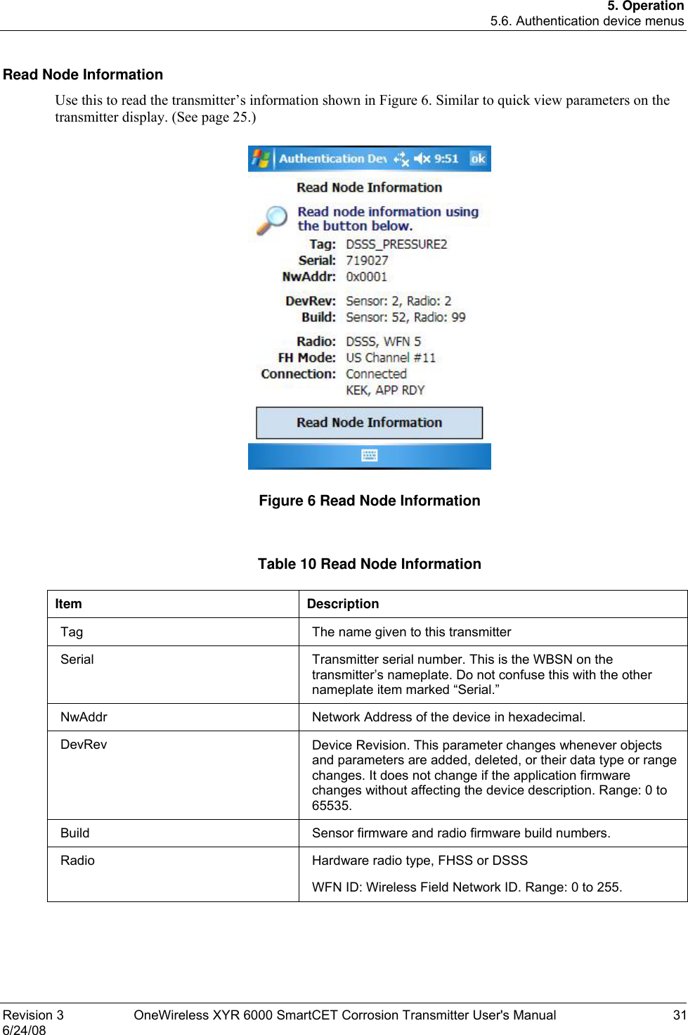
Honeywell 50025034 50025034 User Manual C
Honeywell International Inc. 50025034 C
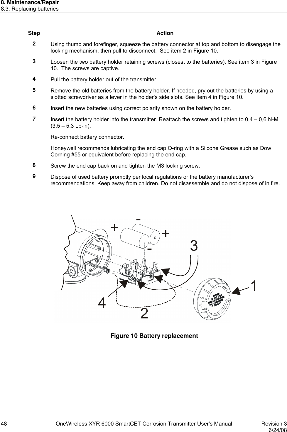
UserManual.wiki
>
Honeywell
>
50025034 User Manual
>
User Manual C
Contents
1.
Pro Install Guide
2.
User Manual C
3.
User Manual A
4.
User Manual B
5.
User Manual D
6.
User Manual E
7.
Install Guide
8.
Quick start guide
9.
User Manual
10.
Installation Guide
User Manual C
Navigation menu
Upload a User Manual
Namespaces
Wiki Guide
HTML
PDF
Info
Views
User Manual
Discussion / Help
Navigation
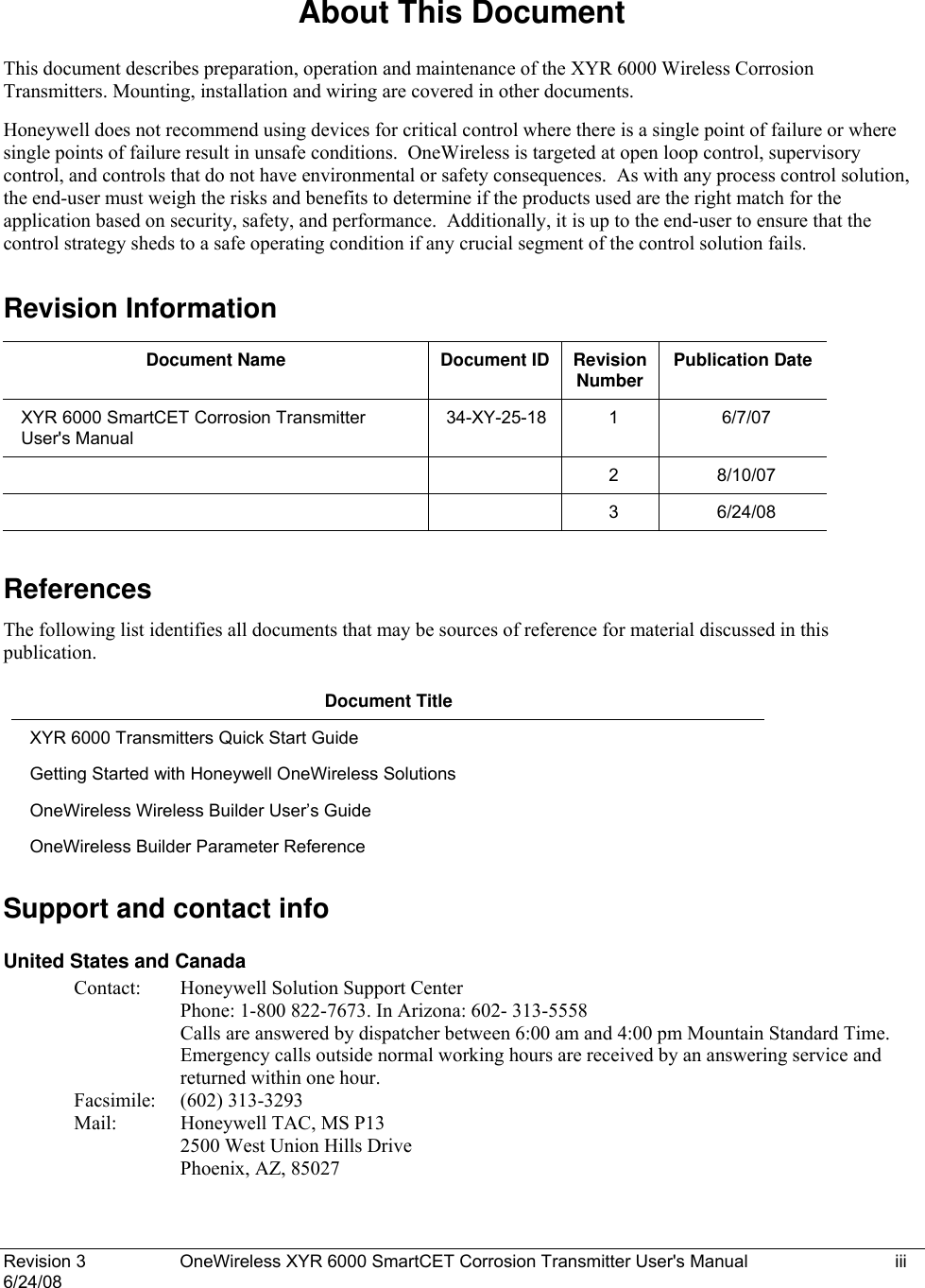
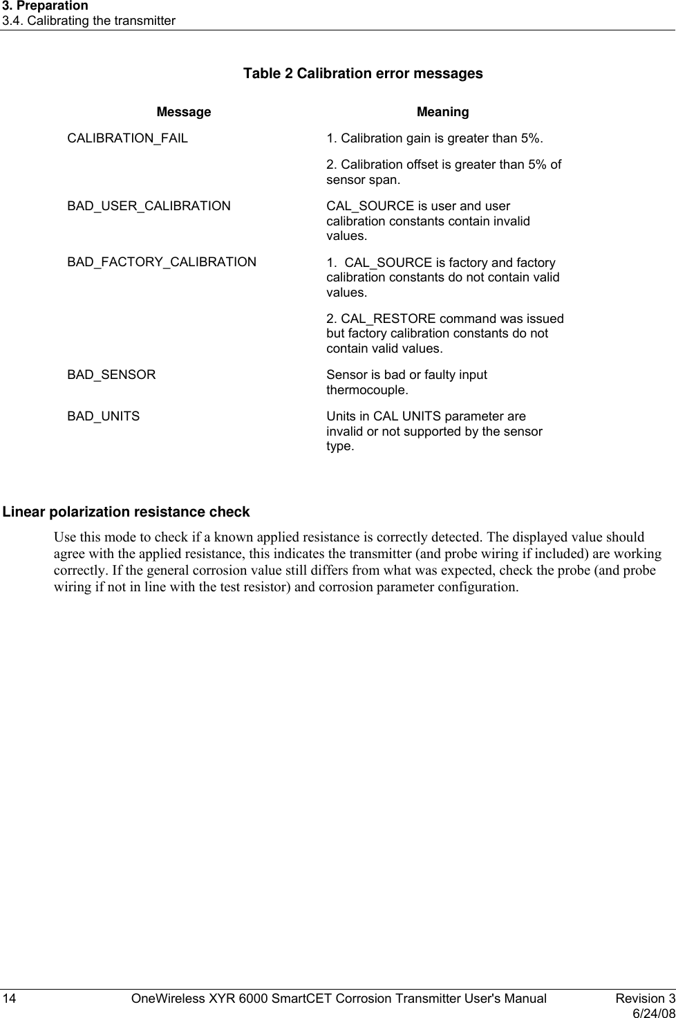
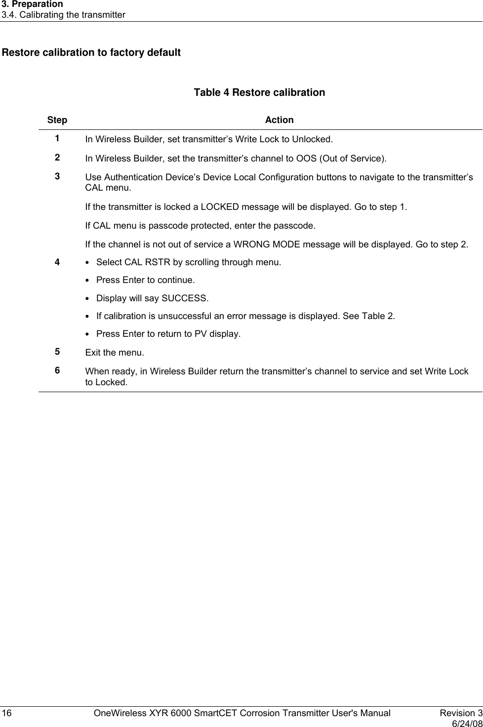
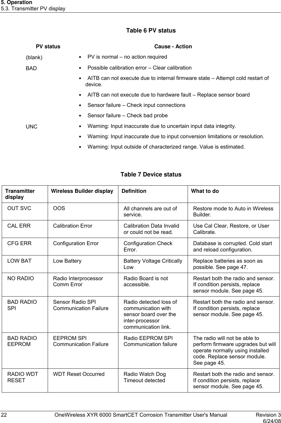
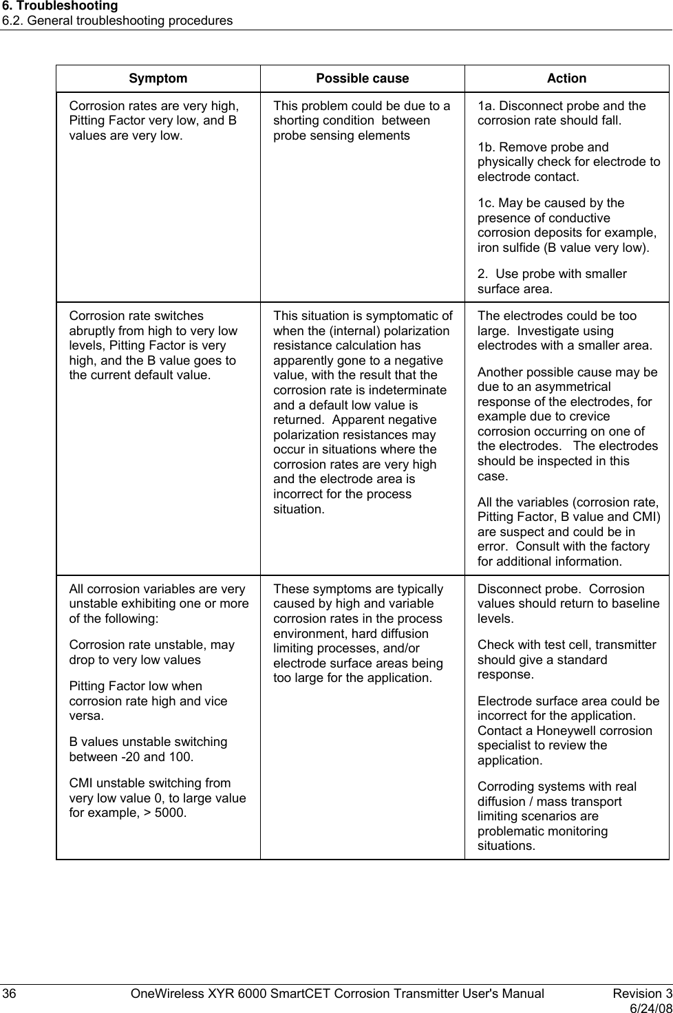
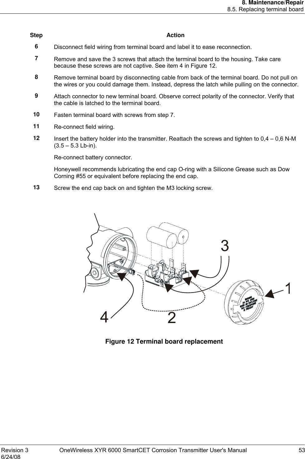
![2. Specifications 2.5. Probes 10 OneWireless XYR 6000 SmartCET Corrosion Transmitter User's Manual Revision 3 6/24/08 Authentication Device Install the Authentication Device application on any PDA having • Windows Mobile version 4.2+ • infrared port. 2.5 Probes Electrode area Three finger electrodes = 4.75 cm2 Nine interleaved electrodes = 0.32 cm2 Three flush disks = 0.40 cm2 Constants for common probe materials UNS Number Material Atomic Mass (grams) Density (grams/cm3) Number of electrons lost on oxidation (typical) A91100 Aluminum 1100 27.20 2.71 3 A92024 Aluminum 2024 28.97 2.77 3 A95083 5083 Al 27.38 2.66 3 C11000 CDA 110ETP 99.9 Cu 63.54 8.89 2 C12200 DHP Cu 63.53 8.89 2 C27000 Yellow Brass 64.32 8.47 2 C44300 CDA443 (ARS AD. Brass) 64.22 8.52 2 C68700 CDA687 (Al Brass) 63.23 8.33 2 C70600 90-10 Cu-Ni [CDA 706 (Cu/Ni 90/10)] 62.95 8.94 2 C71500 CDA 715 (Cu/Ni 70/30) 61.99 8.94 2 G10100 1010 Carbon Steel 55.77 7.87 2 G10180 1018 Carbon Steel 55.75 7.86 2 G10200 1020 Carbon Steel 55.74 7.86 2 G10800 1080 Carbon Steel 55.46 7.84 2 G41400 4140 55.62 7.85 2 K01200 A179 55.77 7.87 2 K01201 A192 55.70 7.86 2 K02598 ASTM A36 55.71 7.86 2 K02700 A516-70 (A516 Gr70) 55.62 7.86 2](https://usermanual.wiki/Honeywell/50025034.User-Manual-C/User-Guide-996149-Page-22.png)
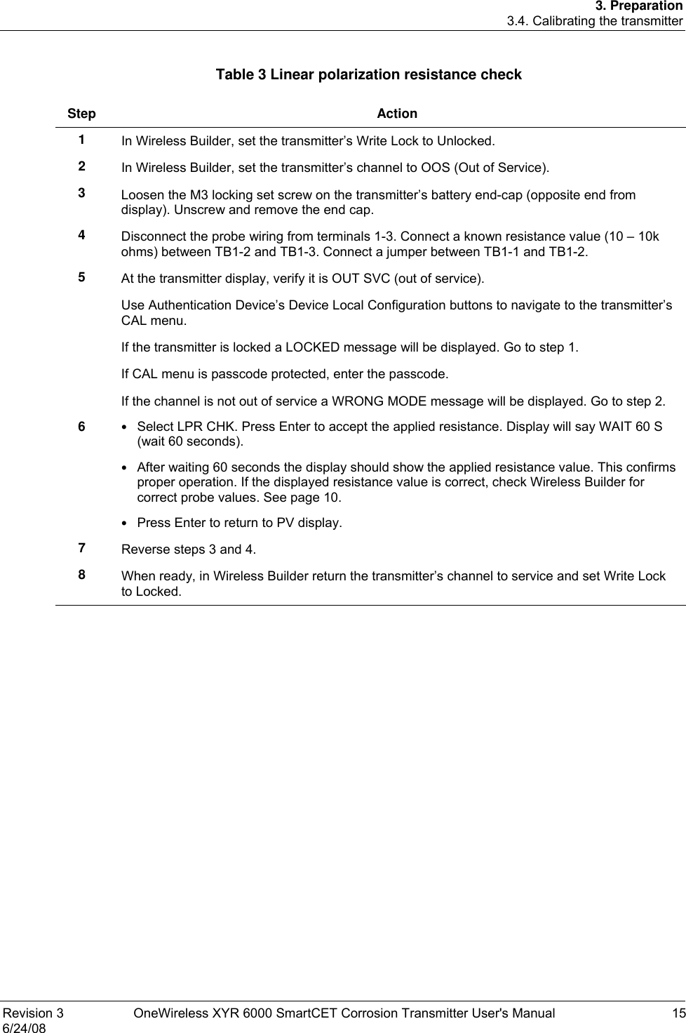
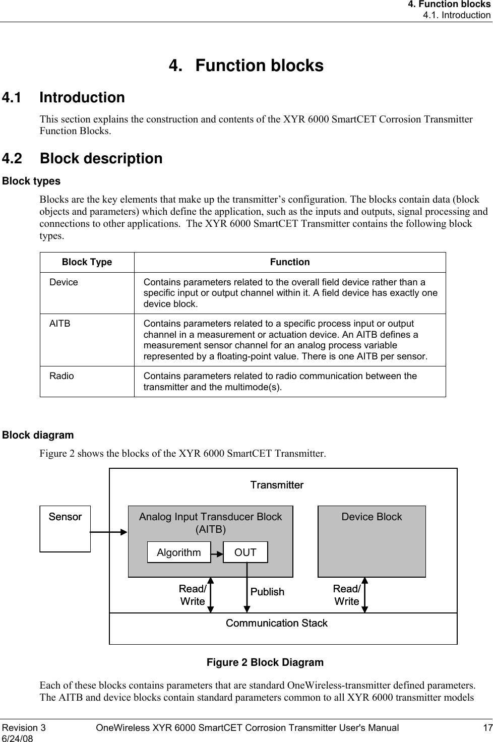
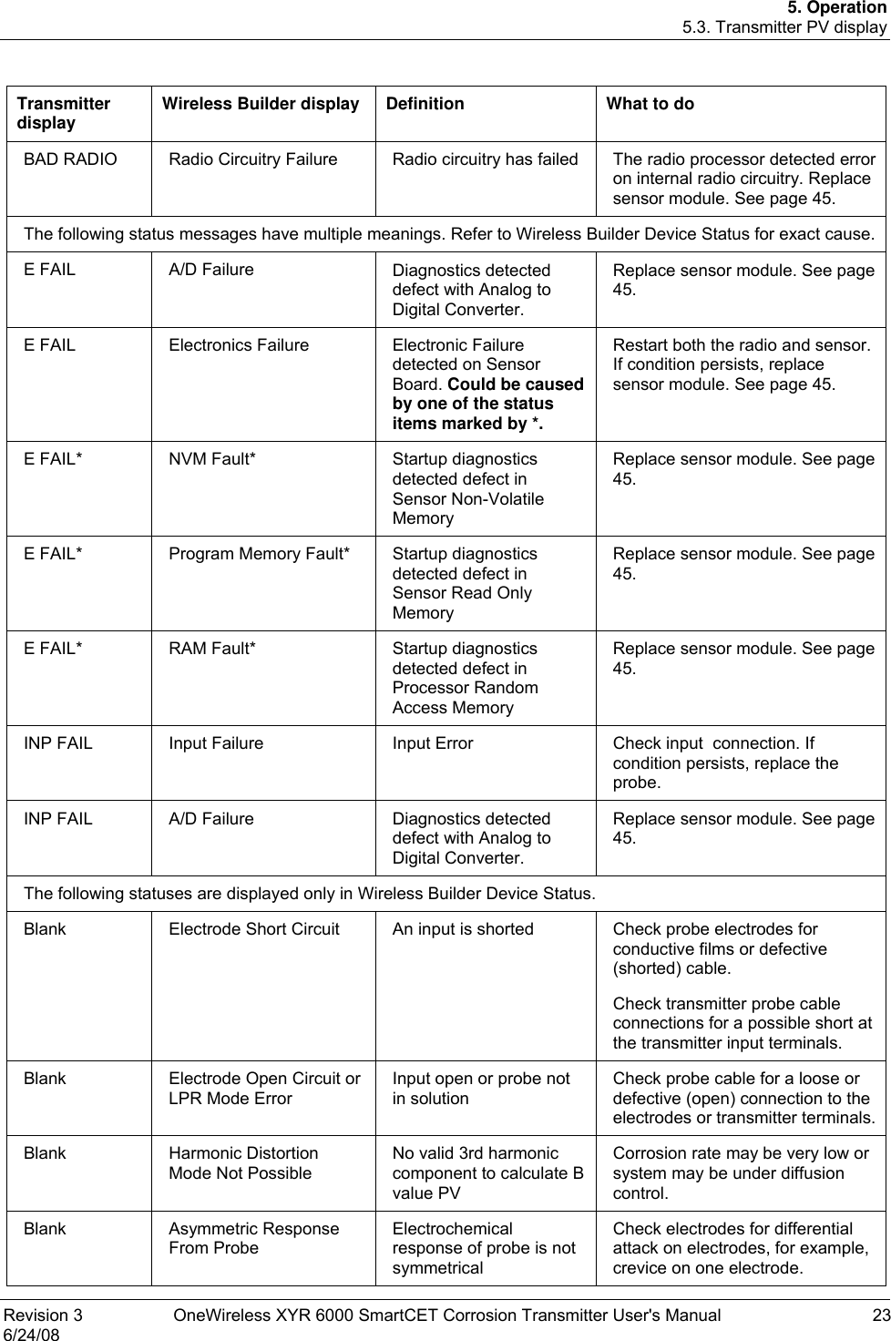
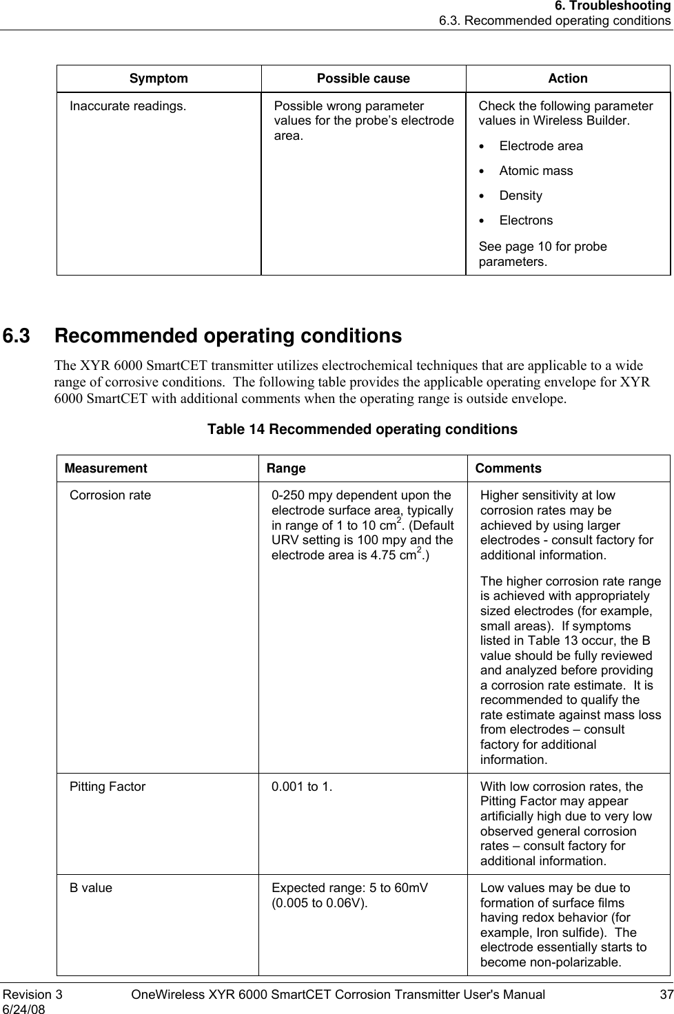
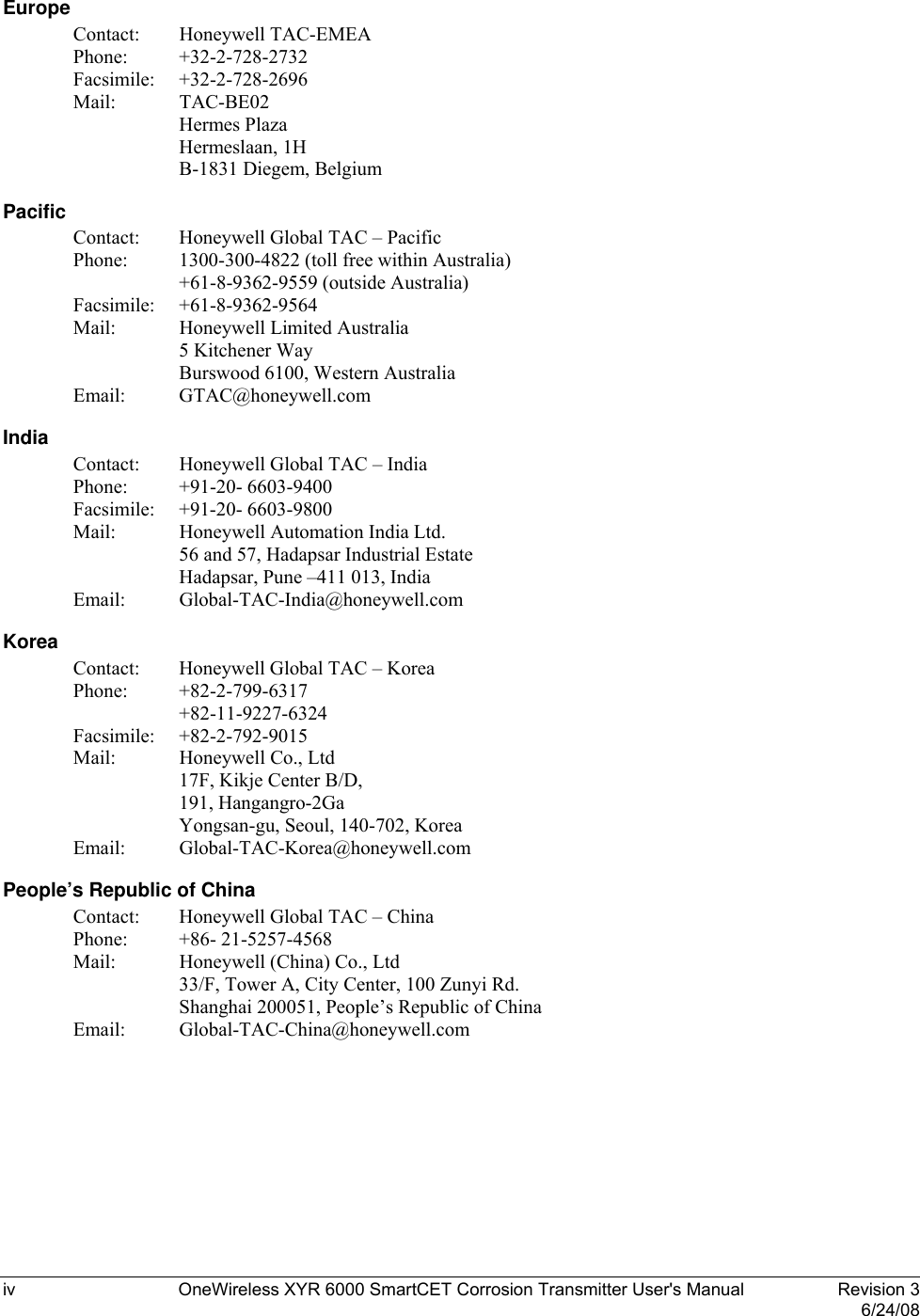
![2. Specifications 2.5. Probes Revision 3 OneWireless XYR 6000 SmartCET Corrosion Transmitter User's Manual 11 6/24/08 UNS Number Material Atomic Mass (grams) Density (grams/cm3) Number of electrons lost on oxidation (typical) K03005 ASTM A53 [Grade B Carbon Steel] 55.68 7.86 2 K03006 A106, Grade B 55.66 7.86 2 K03006 API 5L-X52 55.71 7.86 2 K03006 API 5L-X70 55.71 7.86 2 L13601 60 Sn / 40 Pb 153.97 8.42 3 N04400 Monel 400 59.62 8.80 2 N08020 Carpenter 20 Cb3 57.30 8.08 2 N10276 C-276 [Hastelloy] 63.43 8.89 2 R50400 Titanium GR2 47.79 4.52 4 R60702 Zr 702 95.08 6.10 4 S30400 AISI 304 55.04 7.94 2 S30403 AISI 304L 55.08 7.94 2 S31600 AISI 316 56.19 7.98 2 S31603 AISI 316L 56.22 7.98 2 S41003 Duracorr 55.12 7.70 2 S41425 Mod. 13Cr 56.13 7.70 2 K03005 A53 Grade B Carbon Steel Pipe 55.68142 7.87 2 K02598 ASTM A36 55.71 7.86 2 K03006 A106, Grade B 55.66 7.86 2](https://usermanual.wiki/Honeywell/50025034.User-Manual-C/User-Guide-996149-Page-23.png)