Honeywell 50025034 50025034 User Manual WCX Series Valve Position Sensor
Honeywell International Inc. 50025034 WCX Series Valve Position Sensor
UserManual.wiki
>
Honeywell
>
50025034 User Manual
>
User Manual
Contents
1.
Pro Install Guide
2.
User Manual C
3.
User Manual A
4.
User Manual B
5.
User Manual D
6.
User Manual E
7.
Install Guide
8.
Quick start guide
9.
User Manual
10.
Installation Guide
User Manual
Navigation menu
Upload a User Manual
Namespaces
Wiki Guide
HTML
PDF
Info
Views
User Manual
Discussion / Help
Navigation
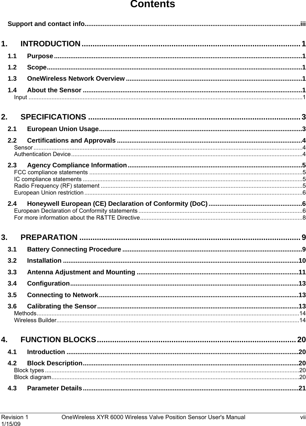
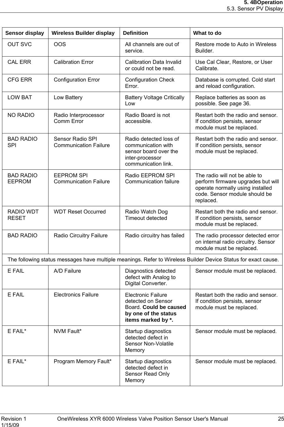
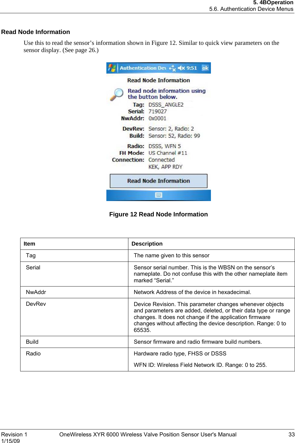
![2. 1BSpecifications 2.2. Certifications and Approvals 4 OneWireless XYR 6000 Wireless Valve Position Sensor User's Manual Revision 1 1/15/09 2.2 Certifications and Approvals Sensor See the product label for applicable approvals and ratings. Approval / Item Ratings / Description cCSAus Explosion Proof with IS outputs Class I, Division 1, Groups A, B, C & D Class II, Division 1, Groups E, F & G Class III ATEX Flameproof with IS outputs II 2 G Ex d [ia] IIB T4 II 2 D Ex tD A21 IP66 T85C IEC Ex Flameproof with IS outputs Ex d [ia] IIB T4: DIP A21 IP66 T85C Enclosure Type Types 1, 3, 4, 4X, 6, 6P, 13 and IP66/67 Class II and III installations and for Type 4X/IP66 applications require that all cable and unused entries be sealed with a Zone 1 certified seal fitting. Seal fittings are supplied by Honeywell. For detailed sensor specifications see the following Specification and Model Selection Guide. • WCX Series Valve Position Sensor Installation Drawing Authentication Device Install the Authentication Device application on any PDA having • Windows Mobile version 4.2+ • infrared port.](https://usermanual.wiki/Honeywell/50025034.User-Manual/User-Guide-1112083-Page-14.png)