Honeywell 50025034 50025034 User Manual WCX Series Valve Position Sensor
Honeywell International Inc. 50025034 WCX Series Valve Position Sensor
UserManual.wiki
>
Honeywell
>
50025034 User Manual
>
Quick start guide
Contents
1.
Pro Install Guide
2.
User Manual C
3.
User Manual A
4.
User Manual B
5.
User Manual D
6.
User Manual E
7.
Install Guide
8.
Quick start guide
9.
User Manual
10.
Installation Guide
Quick start guide
Navigation menu
Upload a User Manual
Namespaces
Wiki Guide
HTML
PDF
Info
Views
User Manual
Discussion / Help
Navigation
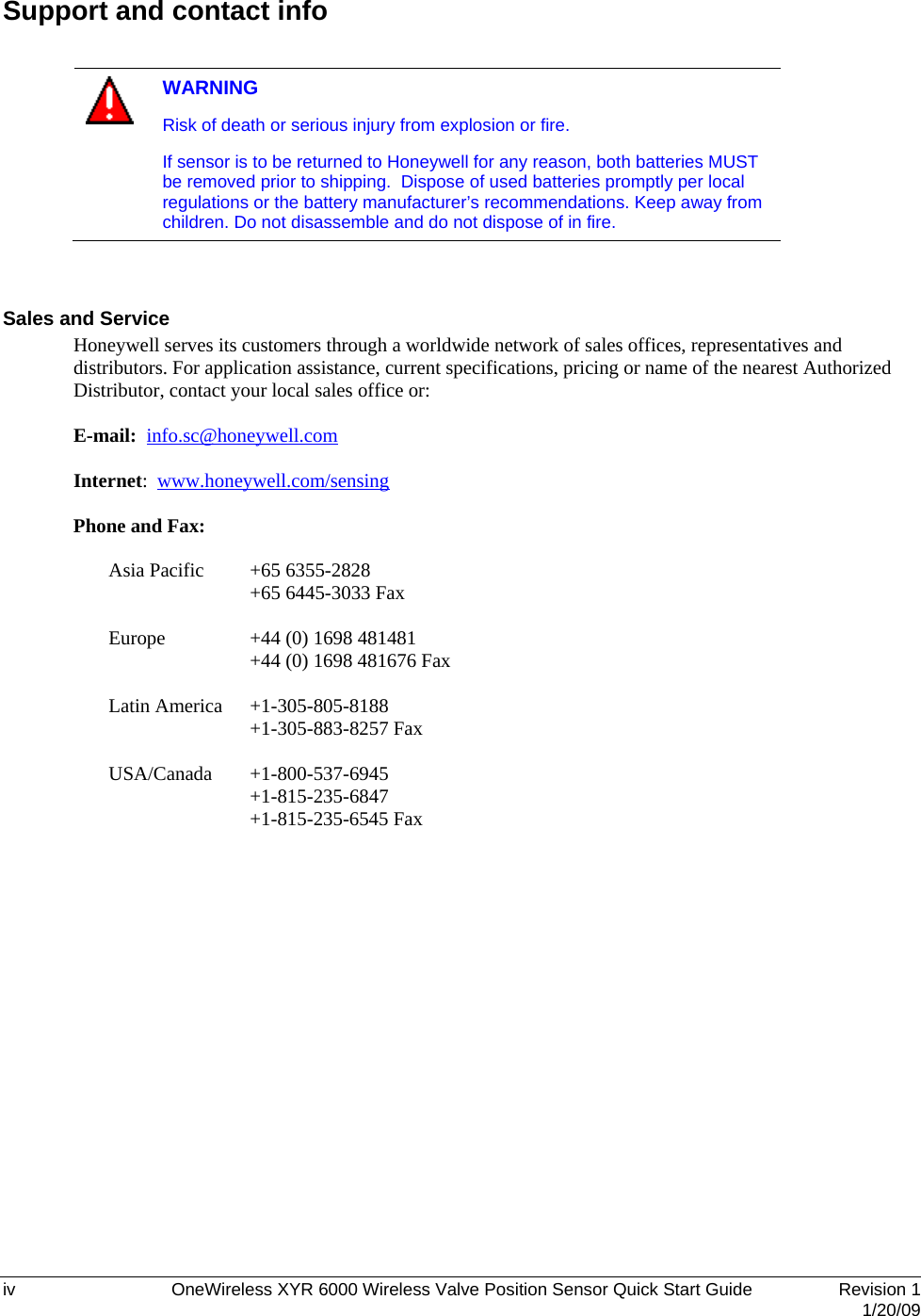
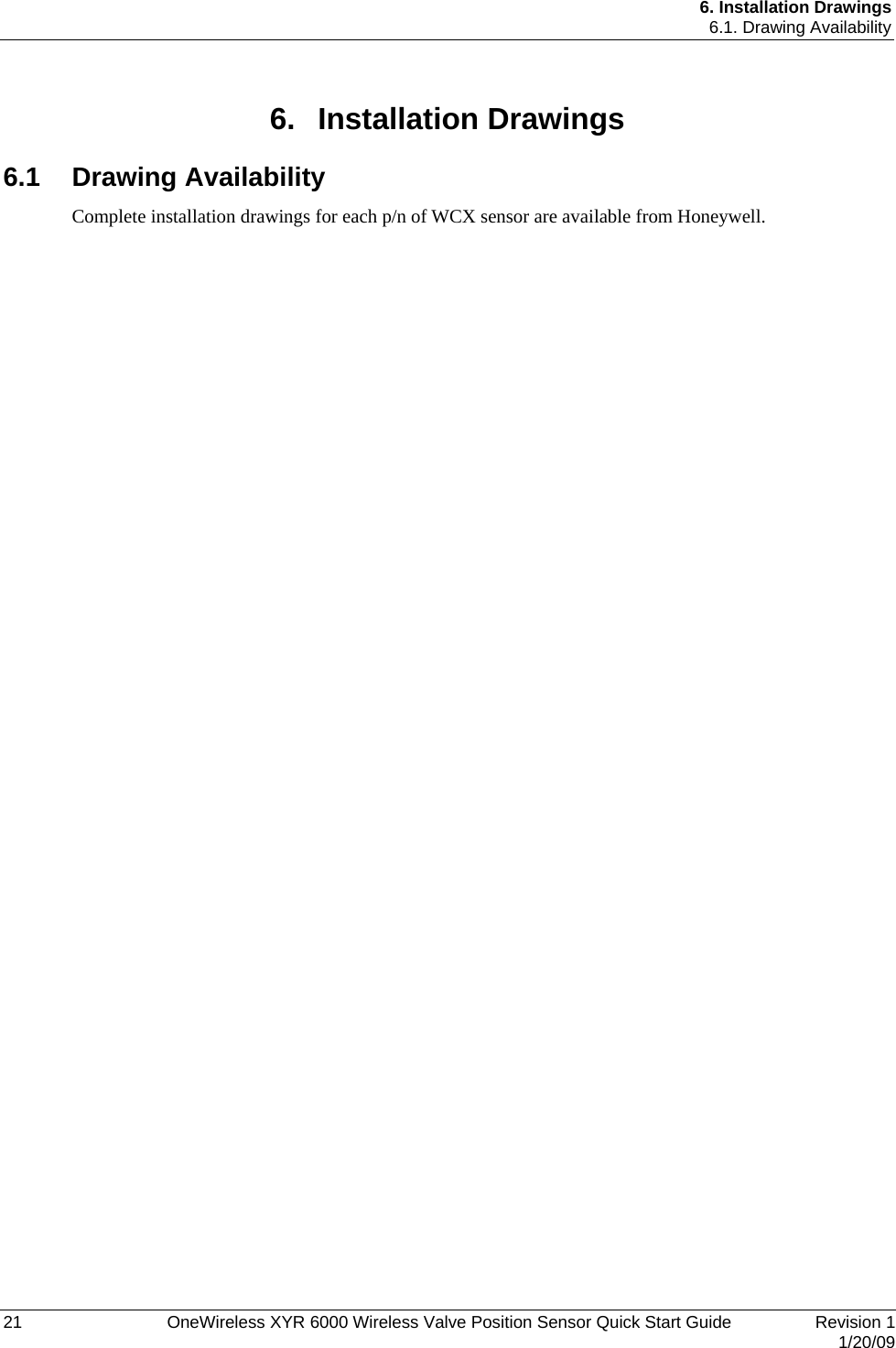
![1. Introduction 1.3. Certifications and approvals 2 OneWireless XYR 6000 Wireless Valve Position Sensor Quick Start Guide Revision 1 1/20/09 1.3 Certifications and approvals Hazardous location certifications Refer to product label for applicable approvals. Approval / Item Ratings / Description cCSAus Explosion Proof with IS outputs Class I, Division 1, Groups A, B, C & D Class II, Division 1, Groups E, F & G Class III ATEX Flameproof with IS outputs II 2 G Ex d [ia] IIB T4 II 2 D Ex tD A21 IP66 T85C IEC Ex Flameproof with IS outputs Ex d [ia] IIB T4: DIP A21 IP66 T85C Enclosure Type Types 1, 3, 4, 4X, 6, 6P, 13 and IP66/67 Class II and III installations and for Type 4X/IP66 applications require that all cable and unused entries be sealed with a Zone 1 certified seal fitting. Seal fittings are supplied by Honeywell. Radio certifications Agency Certification Description Federal Communications Commission (FCC) DSSS FCC ID: S5750025034 The WCX Series Valve Position Sensors comply with part 15 of the FCC rules. Operation is subject to the following two conditions. (1) this device may not cause harmful interference, and (2) this device must accept any interference received, including interference that may cause undesired operation. Industry Canada (IC) DSSS IC ID: 573I-50025034 The installer of this radio equipment must ensure that the antenna is located or pointed such that it does not emit RF fields in excess of Health Canada limits for the general population; consult Safety Code 6, obtainable from Health Canada’s web site www.hc-sc.gc.ca/rpb](https://usermanual.wiki/Honeywell/50025034.Quick-start-guide/User-Guide-1112082-Page-12.png)