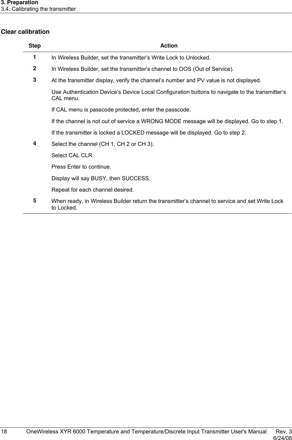
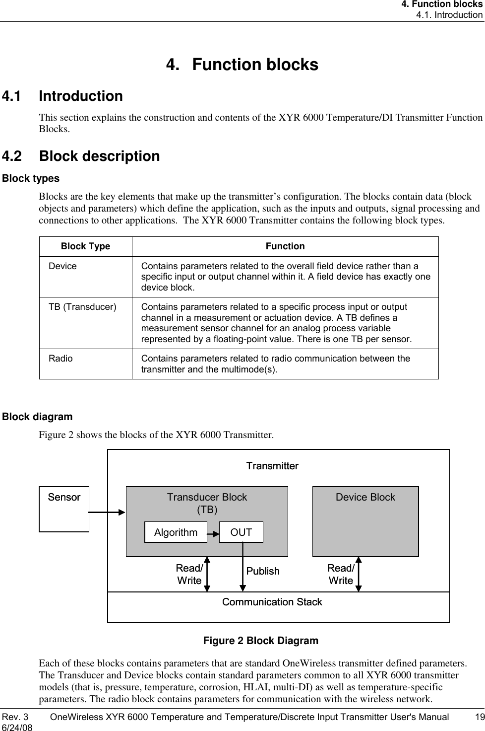
Honeywell 50025034 50025034 User Manual D

Honeywell International Inc. 50025034 D
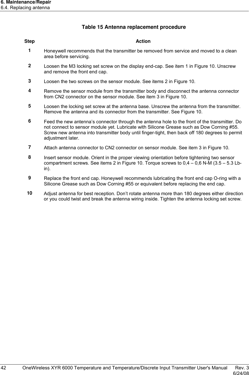
User Manual D

          OneWireless XYR 6000 Temperature and Temperature/Discrete Input Transmitter User's Manual 34-XY-25-16 Revision 3 6/24/08
 ii  OneWireless XYR 6000 Temperature and Temperature/Discrete Input Transmitter User's Manual   Rev. 3   6/24/08 Notices and Trademarks  Copyright 2007 by Honeywell International Inc. Revision 3  June 24, 2008  While this information is presented in good faith and believed to be accurate, Honeywell disclaims the implied warranties of merchantability and fitness for a particular purpose and makes no express warranties except as may be stated in its written agreement with and for its customers. In no event is Honeywell liable to anyone for any indirect, special or consequential damages. The information and specifications in this document are subject to change without notice. Honeywell, PlantScape, Experion PKS, and TotalPlant are registered trademarks of Honeywell International Inc. Other brand or product names are trademarks of their respective owners.         Honeywell International Process Solutions 2500 West Union Hills Phoenix, AZ  85027 1-800 343-0228
 Revision 4OneWireless XYR 6000 Temperature and Temperature/Discrete Input Transmitter User's Manual  iii 6/8/08    About This Document This document describes preparation, operation and maintenance of the XYR 6000 Wireless Temperature/DI Transmitters. Mounting, installation and wiring are covered in other documents. Honeywell does not recommend using devices for critical control where there is a single point of failure or where single points of failure result in unsafe conditions.  OneWireless is targeted at open loop control, supervisory control, and controls that do not have environmental or safety consequences.  As with any process control solution, the end-user must weigh the risks and benefits to determine if the products used are the right match for the application based on security, safety, and performance.  Additionally, it is up to the end-user to ensure that the control strategy sheds to a safe operating condition if any crucial segment of the control solution fails. Revision Information  Document Name  Document ID  Revision Number  Publication Date XYR 6000 Temperature and Temperature/Discrete Input Transmitter User's Manual 34-XY-25-16 1  6/7/07   2 8/7/07   3 6/24/08  References The following list identifies all documents that may be sources of reference for material discussed in this publication.  Document Title XYR 6000 Transmitters Quick Start Guide Getting Started with Honeywell OneWireless Solutions OneWireless Wireless Builder User’s Guide OneWireless Builder Parameter Reference  Support and contact info United States and Canada Contact:   Honeywell Solution Support Center   Phone: 1-800 822-7673. In Arizona: 602- 313-5558   Calls are answered by dispatcher between 6:00 am and 4:00 pm Mountain Standard Time. Emergency calls outside normal working hours are received by an answering service and returned within one hour. Facsimile:   (602) 313-3293 Mail:   Honeywell TAC, MS P13   2500 West Union Hills Drive   Phoenix, AZ, 85027
 iv  OneWireless XYR 6000 Temperature and Temperature/Discrete Input Transmitter User's Manual Revision 4   6/24/08 Europe Contact:   Honeywell TAC-EMEA Phone:   +32-2-728-2732 Facsimile:   +32-2-728-2696 Mail:   TAC-BE02  Hermes Plaza  Hermeslaan, 1H  B-1831 Diegem, Belgium Pacific Contact:   Honeywell Global TAC – Pacific Phone:   1300-300-4822 (toll free within Australia)  +61-8-9362-9559 (outside Australia) Facsimile:   +61-8-9362-9564 Mail:   Honeywell Limited Australia   5 Kitchener Way   Burswood 6100, Western Australia Email: GTAC@honeywell.com India Contact:   Honeywell Global TAC – India Phone:   +91-20- 6603-9400 Facsimile:   +91-20- 6603-9800 Mail:   Honeywell Automation India Ltd.   56 and 57, Hadapsar Industrial Estate   Hadapsar, Pune –411 013, India Email:   Global-TAC-India@honeywell.com Korea Contact:   Honeywell Global TAC – Korea Phone:   +82-2-799-6317  +82-11-9227-6324 Facsimile:   +82-2-792-9015 Mail:   Honeywell Co., Ltd   17F, Kikje Center B/D,  191, Hangangro-2Ga   Yongsan-gu, Seoul, 140-702, Korea Email:   Global-TAC-Korea@honeywell.com People’s Republic of China  Contact:   Honeywell Global TAC – China Phone:   +86- 21-5257-4568 Mail:   Honeywell (China) Co., Ltd   33/F, Tower A, City Center, 100 Zunyi Rd.   Shanghai 200051, People’s Republic of China Email: Global-TAC-China@honeywell.com
 Revision 4OneWireless XYR 6000 Temperature and Temperature/Discrete Input Transmitter User's Manual  v 6/24/08  Singapore  Contact:   Honeywell Global TAC – South East Asia Phone:   +65-6580-3500 Facsimile:   +65-6580-3501  +65-6445-3033 Mail:   Honeywell Private Limited  Honeywell Building   17, Changi Business Park Central 1  Singapore 486073 Email: GTAC-SEA@honeywell.com Taiwan Contact:   Honeywell Global TAC – Taiwan Phone:   +886- 7- 536-2567 Facsimile:   +886-7-536-2039 Mail:   Honeywell Taiwan Ltd.   17F-1, No. 260, Jhongshan 2nd Road.   Cianjhen District   Kaohsiung, Taiwan, ROC Email: Global-TAC-Taiwan@honeywell.com Japan Contact:   Honeywell Global TAC – Japan Phone:   +81-3-6730-7160 Facsimile:   +81-3-6730-7228 Mail:   Honeywell Japan Inc.   New Pier Takeshiba, South Tower Building,   20th Floor, 1-16-1 Kaigan, Minato-ku,  Tokyo 105-0022, Japan Email: Global-TAC-JapanJA25@honeywell.com World Wide Web Honeywell Solution Support Online: http://www.honeywell.com/ps Elsewhere Call your nearest Honeywell office. Training Classes Honeywell Automation College: http://www.automationcollege.com
 vi  OneWireless XYR 6000 Temperature and Temperature/Discrete Input Transmitter User's Manual Revision 4   6/24/08 Symbol Definitions The following table lists those symbols used in this document to denote certain conditions.  Symbol Definition     ATTENTION: Identifies information that requires special consideration.     TIP: Identifies advice or hints for the user, often in terms of performing a task.   CAUTION  Indicates a situation which, if not avoided, may result in equipment or work (data) on the system being damaged or lost, or may result in the inability to properly operate the process.      CAUTION: Indicates a potentially hazardous situation which, if not avoided, may result in minor or moderate injury. It may also be used to alert against unsafe practices.  CAUTION symbol on the equipment refers the user to the product manual for additional information. The symbol appears next to required information in the manual.     WARNING: Indicates a potentially hazardous situation, which, if not avoided, could result in serious injury or death. WARNING symbol on the equipment refers the user to the product manual for additional information. The symbol appears next to required information in the manual.     WARNING, Risk of electrical shock: Potential shock hazard where HAZARDOUS LIVE voltages greater than 30 Vrms, 42.4 Vpeak, or 60 VDC may be accessible.     ESD HAZARD: Danger of an electro-static discharge to which equipment may be sensitive. Observe precautions for handling electrostatic sensitive devices.     Protective Earth (PE) terminal: Provided for connection of the protective earth (green or green/yellow) supply system conductor.     Functional earth terminal: Used for non-safety purposes such as noise immunity improvement. NOTE: This connection shall be bonded to Protective Earth at the source of supply in accordance with national local electrical code requirements.     Earth Ground: Functional earth connection. NOTE: This connection shall be bonded to Protective Earth at the source of supply in accordance with national and local electrical code requirements.     Chassis Ground: Identifies a connection to the chassis or frame of the equipment shall be bonded to Protective Earth at the source of supply in accordance with national and local electrical code requirements. continued
 Revision 4OneWireless XYR 6000 Temperature and Temperature/Discrete Input Transmitter User's Manual  vii 6/24/08  Symbol  Description  The Factory Mutual® Approval mark means the equipment has been rigorously tested and certified to be reliable.   The Canadian Standards mark means the equipment has been tested and meets applicable standards for safety and/or performance.  The Ex mark means the equipment complies with the requirements of the European standards that are harmonised with the 94/9/EC Directive (ATEX Directive, named after the French "ATmosphere EXplosible").  For radio equipment used in the European Union in accordance with the R&TTE Directive the CE Mark and the notified body (NB) identification number is used when the NB is involved in the conformity assessment procedure.  The alert sign must be used when a restriction on use (output power limit by a country at certain frequencies) applies to the equipment and must follow the CE marking.  The C-Tick mark is a certification trade mark registered to ACMA (Australian Communications and Media Authority) in Australia under the Trade Marks Act 1995 and to RSM in New Zealand under section 47 of the NZ Trade Marks Act. The mark is only to be used in accordance with conditions laid down by ACMA and RSM.  This mark is equal to the CE Mark used in the European Union.  N314 directly under the logo is Honeywell’s unique supplier identification number.
 Rev. 3  OneWireless XYR 6000 Temperature and Temperature/Discrete Input Transmitter User's Manual  ix 6/24/08
 Rev. 3  OneWireless XYR 6000 Temperature and Temperature/Discrete Input Transmitter User's Manual  xi 6/24/08    Contents  1. INTRODUCTION....................................................................................................1 1.1 Purpose..........................................................................................................................................1 1.2 Scope..............................................................................................................................................1 1.3 OneWireless network overview ...................................................................................................1 1.4 About the transmitter....................................................................................................................1 Inputs......................................................................................................................................................................1 2. SPECIFICATIONS .................................................................................................3 2.1 European Union Usage.................................................................................................................3 2.2 Certifications and approvals........................................................................................................4 Transmitter .............................................................................................................................................................4 Authentication Device...........................................................................................................................................10 3. PREPARATION ...................................................................................................11 3.1 Installation ...................................................................................................................................11 3.2 Configuration...............................................................................................................................11 3.3 Connecting to network ...............................................................................................................11 3.4 Calibrating the transmitter .........................................................................................................11 Methods of calibration ..........................................................................................................................................11 User calibration ....................................................................................................................................................12 Wiring for calibration.............................................................................................................................................14 Restore calibration................................................................................................................................................17 Clear calibration....................................................................................................................................................18 4. FUNCTION BLOCKS........................................................................................... 19 4.1 Introduction .................................................................................................................................19 4.2 Block description ........................................................................................................................19 Block types ...........................................................................................................................................................19 Block diagram.......................................................................................................................................................19 4.3 Parameter details ........................................................................................................................20 5. OPERATION ........................................................................................................21 5.1 Overview ......................................................................................................................................21 Transmitter display modes ...................................................................................................................................21 Authentication Device...........................................................................................................................................21 5.2 Transmitter connection status...................................................................................................22 5.3 Transmitter PV display ...............................................................................................................23 5.4 Transmitter quick view of parameters ......................................................................................27
Contents  xii  OneWireless XYR 6000 Temperature and Temperature/Discrete Input Transmitter User's Manual   Rev. 3   6/24/08 5.5 Transmitter menu........................................................................................................................28 Menu tree.............................................................................................................................................................28 5.6 Authentication device menus ....................................................................................................29 Overview..............................................................................................................................................................29 Main menu ...........................................................................................................................................................29 Security and Node Deployment ........................................................................................................................... 30 Device Local Configuration ..................................................................................................................................32 Read Node Information........................................................................................................................................33 Advanced Options................................................................................................................................................35 6. MAINTENANCE/REPAIR .................................................................................... 36 6.1 Parts .............................................................................................................................................36 6.2 Replacing batteries .....................................................................................................................37 When to replace...................................................................................................................................................37 Tools required ......................................................................................................................................................37 Procedure ............................................................................................................................................................37 6.3 Replacing sensor module ..........................................................................................................39 When to replace...................................................................................................................................................39 Tools required ......................................................................................................................................................39 Procedure ............................................................................................................................................................39 6.4 Replacing antenna ......................................................................................................................41 Tools required ......................................................................................................................................................41 Procedure ............................................................................................................................................................41 6.5 Replacing terminal board...........................................................................................................44 When to replace...................................................................................................................................................44 Tools required ......................................................................................................................................................44 Procedure ............................................................................................................................................................44
Contents Tables Rev. 3  OneWireless XYR 6000 Temperature and Temperature/Discrete Input Transmitter User's Manual  xiii 6/24/08 Tables Table 1 User calibration: T/C and RTD .......................................................................................................12 Table 2 User calibration: ohms (STTW400 only).........................................................................................13 Table 3 Calibration error messages ............................................................................................................16 Table 4 Transmitter connection status ........................................................................................................22 Table 5 Transmitter PV Display...................................................................................................................23 Table 6 PV engineering units ......................................................................................................................23 Table 7 PV status ........................................................................................................................................24 Table 8 Device status ..................................................................................................................................24 Table 9 Menu tree........................................................................................................................................28 Table 10 Buttons for Device Local Configuration ........................................................................................32 Table 11 Read Node Information ................................................................................................................33 Table 12 Advanced Options ........................................................................................................................35 Table 13 Battery replacement procedure ....................................................................................................38 Table 14 Sensor module replacement.........................................................................................................40 Table 15 Antenna replacement procedure ..................................................................................................42 Table 16 Terminal board replacement procedure .......................................................................................44
Contents Figures xiv  OneWireless XYR 6000 Temperature and Temperature/Discrete Input Transmitter User's Manual   Rev. 3   6/24/08 Figures Figure 1  XYR 6000 Functional Diagram.......................................................................................................2 Figure 2 Block Diagram ...............................................................................................................................19 Figure 3 Main menu.....................................................................................................................................29 Figure 4 Security and Node Deployment.....................................................................................................30 Figure 5 Device Local Configuration screen................................................................................................32 Figure 6 Read Node Information .................................................................................................................33 Figure 7 Advanced Options .........................................................................................................................35 Figure 8 Battery replacement ......................................................................................................................38 Figure 9 Sensor module removal and replacement ....................................................................................40 Figure 10 Antenna replacement ..................................................................................................................43 Figure 11 Terminal board replacement .......................................................................................................45
1. Introduction 1.1. Purpose Rev. 3  OneWireless XYR 6000 Temperature and Temperature/Discrete Input Transmitter User's Manual  1 6/24/08 1. Introduction 1.1 Purpose This manual describes the Honeywell OneWireless XYR 6000 Temperature/DI Transmitter function, operation and maintenance. 1.2 Scope The manual includes: •  Details of topics that relate uniquely to the Honeywell XYR 6000 Temperature/DI Transmitter, •  This manual does not cover installation, mounting, or wiring. See XYR 6000 Transmitter Quick Start Guide (document 34-XY-25-21). 1.3  OneWireless network overview OneWireless is an all digital, serial, two-way communication mesh network that interconnects industrial field sensors to a central system.  OneWireless has defined standards to which field devices and operator stations communicate with one another.  The communications protocol is built as an "open system" to allow all field devices and equipment that are built to OneWireless standard to be integrated into a system, regardless of the device manufacturer.  This interoperability of devices using OneWireless technology is to become an industry standard for automation systems. 1.4  About the transmitter The XYR 6000 Temperature/DI Transmitter is furnished with OneWireless interface to operate in a compatible distributed OneWireless system.  The transmitter will interoperate with any OneWireless-registered device.  The transmitter includes OneWireless electronics for operating in a 2.4GHz network.  It features function block architecture. Inputs The transmitter supports three input channels in various configurations depending on model.  •  Up to 3 T/C or millivolt channels (STTW400) •  Up to 2 RTD channels (STTW400) •  Channel 3 must be T/C or mV (STTW400) •  Channels 2 and 3 are discrete inputs (DI) and channel 1 is T/C or millivolt (STTW401) continued
1. Introduction 1.4. About the transmitter 2  OneWireless XYR 6000 Temperature and Temperature/Discrete Input Transmitter User's Manual   Rev. 3   6/24/08 •  Input types −  Thermocouple (B ,E, J, K, N, R, S, T) (all models) −  RTD (Pt100, Pt200, Pt500) (STTW400) −  mV (0 to 10, 0 to 50, 0 to 100) (all models) −  Ohm (0 to 100, 0 to 200, 0 to 500, 0 to 1000) (STTW400) The transmitter measures the analog signal from temperature sensors, discrete inputs, millivolt or ohm values and transmits a digital output signal proportional to the measured value for direct digital communications with systems.  The discrete input channels support voltage-free floating contacts. Maximum ON contact resistance is 300 ohms. Minimum OFF contact resistance is 5000 ohms. The Process Variable (PV) is available for monitoring and alarm purposes. The cold junction temperature is also available as a fourth channel PV. Available PV update rates are 1, 5, 10, 30 seconds and are set on Wireless Builder. Slower update rates extend battery life.   Figure 1 shows a block diagram of the XYR 6000 Temperature transmitter’s operating functions.  EEPROMA/DCH 1Multi-plexerElectronics HousingRadioBoardInputTCRTDmVOhmMicro-processorMicro-processorEEPROMBatteryAntennaMeasurementBoardConfigurationDataCH 2CH 3  Figure 1  XYR 6000 Functional Diagram
2. Specifications 2.1. European Union Usage Rev. 3  OneWireless XYR 6000 Temperature and Temperature/Discrete Input Transmitter User's Manual  3 6/24/08 2. Specifications 2.1 European Union Usage  This product may be used in any of the following European Union nations. Country  ISO 3166  2 letter code  Country   ISO 3166  2 letter code Austria AT  Latvia  LV Belgium BE  Liechtenstein LI Bulgaria BG  Lithuania  LT Cyprus CY  Malta  MT Czech Republic  CZ  Netherlands  NL Denmark DK  Norway  NO Estonia EE  Poland  PL Finland FI  Portugal  PT France FR  Romania  RO Germany DE  Slovakia  SK Greece GR  Slovenia  SI Hungary HU  Spain  ES Iceland IS  Sweden  SE Ireland IE  Switzerland CH Italy IT  United Kingdom BG
2. Specifications 2.2. Certifications and approvals 4  OneWireless XYR 6000 Temperature and Temperature/Discrete Input Transmitter User's Manual   Rev. 3   6/24/08 2.2  Certifications and approvals Transmitter See the product label for applicable approvals and ratings. Approval / Item  Ratings / Description CSAcus Intrinsically Safe  CL I, Div 1, Groups A, B, C, & D; CL II, Div 1, Groups E, F & G; CL III, T4 CL I, Zone 0: Ex ia IIC, T4; CL I, Zone 0: AEx ia IIC, T4  CSAcus Explosionproof  CL I, Div 1, Groups A, B, C, & D; CL II, Div 1, Groups E, F & G; CL III, T4 CL I, Zone 1: Ex d IIC, T4; CL I, Zone 1: AEx d IIC, T4 CSAcus Nonincendive  CL I, Div 2, Groups A, B, C & D; CL II, Div 2, Groups F & G; CL III, Div 2, T4 CL I, Zone 2: Ex nA IIC, T4; CL I, Zone 2: AEx nA IIC, T4 FM Approvals Intrinsically Safe CL I, Div 1, Groups A, B, C, & D; CL II, Div 1, Groups E, F & G; CL III, T4 CL I, Zone 0: AEx ia IIC, T4  FM Approvals Explosionproof CL I, Div 1, Groups A, B, C, & D; CL II, Div 1, Groups E, F & G; CL III, T4 CL I, Zone 1: AEx d IIC, T4 FM Approvals Nonincendive CL I, Div 2, Groups A, B, C & D; CL II, Div 2, Groups F & G; CL III, Div 2, T4 CL I, Zone 2: AEx nA IIC, T4 HON – ATEX Non-Sparking , Ex nA IIC, T4; Ta = 85°C, Zone 2 Process Connections in Division 2 / Zone 2    Division 2 / Zone 2 apparatus may only be connected to processes classified as non-hazardous or Division 2 / Zone 2. Connection to hazardous (flammable or ignition capable) Division 1 / Zone 0, or 1 process is not permitted. Enclosure Type  Type 4X, IP 66/67 CRN  Canadian Registration Number Class II and III installations and for Type 4X/IP66 applications require that all cable and unused entires be sealed with an NRTL listed cable gland or seal fitting. Cable glands and seal fittings are not supplied by Honeywell. For detailed transmitter specifications see the following Specification and Model Selection Guide. •  XYR 6000 Wireless Transmitter Temperature/DI (document 34-XY-03-29)
2. Specifications 2.3. Agency compliance information Rev. 3  OneWireless XYR 6000 Temperature and Temperature/Discrete Input Transmitter User's Manual  5 6/24/08  2.3 Agency compliance information This section contains the Federal Communications Commission (FCC), Industry Canada (IC) and Radio Frequency compliance statements for the OneWireless Multinode device.    ATTENTION XYR6000 units must be professionally installed in accordance with the requirements specified in the OneWireless XYR6000 Agency Compliance Professional Installation Guide.   FCC compliance statements •  This device complies with Part 15 of FCC Rules and Regulations. Operation is subject to the following two conditions: (1) This device may not cause harmful interference and (2) this device must accept any interference received, including interference that may cause undesired operation.  •  This equipment has been tested and found to comply with the limits for a Class A digital device, pursuant to Part 15 of the FCC Rules. These limits are designed to provide reasonable protection against harmful interference in a residential installation. This equipment generates, uses, and can radiate radiofrequency energy and, if not installed and used in accordance with these instructions, may cause harmful interference to radio communications. Operation of this equipment in a residential area is likely to cause harmful interference in which case the user will be required to correct the interference at his own expense.  •  Intentional or unintentional changes or modifications must not be made to the Multinode unless under the express consent of the party responsible for compliance. Any such modifications could void the user’s authority to operate the equipment and will void the manufacturer’s warranty. IC compliance statements •  To reduce potential radio interference to other users, the antenna type and its gain should be so chosen that the equivalent isotropic radiated power (EIRP) is not more than that permitted for successful communication.   •  Operation is subject to the following two conditions: (1) this device may not cause interference, and (2) this device must accept any interference, including interference that may cause undesired operation of the device.  •  This Class A digital apparatus complies with Canadian ICES-003.  •  French: Cet appareil numérique de la classe A est conforme à la norme NMB-003 du Canada. Radio Frequency (RF) statement To comply with FCC’s and Industry Canada’s RF exposure requirements, the following antenna installation and device operating configurations must be satisfied.  •  Remote Point-to-Multi-Point antenna(s) for this unit must be fixed and mounted on outdoor permanent structures with a separation distance between the antenna(s) of greater than 20cm and a separation distance of at least 20cm from all persons.  •  Remote Fixed Point–to-Point antenna(s) for this unit must be fixed and mounted on outdoor permanent structures with a separation distance between the antenna(s) of greater than 20cm and a separation distance of at least 100cm from all persons.
2. Specifications 2.3. Agency compliance information 6  OneWireless XYR 6000 Temperature and Temperature/Discrete Input Transmitter User's Manual   Rev. 3   6/24/08 •  Furthermore, when using integral antenna(s) the Multinode unit must not be co-located with any other antenna or transmitter device and have a separation distance of at least 20cm from all persons.  European Union restriction France restricts outdoor use to 10mW (10dBm) EIRP in the frequency range of 2,454-2,483.5 MHz.  Installations in France must limit EIRP to 10dBm, for operating modes utilizing frequencies in the range of 2,454 – 2,483.5MHz.
2. Specifications 2.4. Honeywell European (CE) Declaration of Conformity (DoC) Rev. 3  OneWireless XYR 6000 Temperature and Temperature/Discrete Input Transmitter User's Manual  7 6/24/08  2.4  Honeywell European (CE) Declaration of Conformity (DoC)  This section contains the European Declaration of Conformity (DoC) statement, for the OneWireless product line.   R&TTE Directive  1999/5/EC  LVD Directive  73/23/EEC  EMC Directive  2004/108/EC  ATEX Directive  94/9/ECHarmonized Standards Emissions Specification and Method: EN 300 328 V1.7.1  Emissions Spec and Method: EN 301 893 V1.4.1  Immunity Specification:  EN 301 489-17 V1.2.1 Immunity Method:  EN 301 489-1 V1.6.1  Product Standard: IEC61326-1 (1st Edition, 2002-02, Industrial Locations)  EN 50014:1992, "Electrical Apparatus for Potentially Explosive Atmospheres –  General Requirements" EN 50021:1999, "Electrical Apparatus for Potentially Explosive Atmospheres –  Type of Protection "n"  Manufacturer’s Name and Address Honeywell Process Solutions  2500 West Union Hills Drive, Phoenix, AZ 85027, USA Compliance Statement  The product herewith complies with the harmonized standards listed above. Typical product line systems and configurations have been tested, for compliance.
2. Specifications 2.4. Honeywell European (CE) Declaration of Conformity (DoC) 8  OneWireless XYR 6000 Temperature and Temperature/Discrete Input Transmitter User's Manual   Rev. 3   6/24/08   European Declaration of Conformity statements  Language Statement Česky (Czech):  Honeywell tímto prohlašuje, že tento Multinode je ve shodě se základními požadavky a dalšími příslušnými ustanoveními směrnice 1999/5/ES. Dansk (Danish): Undertegnede Honeywell erklærer herved, at følgende udstyr Multinode overholder de væsentlige krav og øvrige relevante krav i direktiv 1999/5/EF. Deutsch (German): Hiermit erklärt Honeywell, dass sich das Gerät Multinode in Übereinstimmung mit den grundlegenden Anforderungen und den übrigen einschlägigen Bestimmungen der Richtlinie 1999/5/EG befindet. Eesti (Estonian): Käesolevaga kinnitab Honeywell seadme Multinode vastavust direktiivi 1999/5/EÜ põhinõuetele ja nimetatud direktiivist tulenevatele teistele asjakohastele sätetele. English  Hereby, Honeywell, declares that this Multinode is in compliance with the essential requirements and other relevant provisions of Directive 1999/5/EC. Español (Spanish): Por medio de la presente Honeywell declara que el Multinode cumple con los requisitos esenciales y cualesquiera otras disposiciones aplicables o exigibles de la Directiva 1999/5/CE. Ελληνική (Greek): ΜΕ ΤΗΝ ΠΑΡΟΥΣΑ Honeywell ∆ΗΛΩΝΕΙ ΟΤΙ Multinode ΣΥΜΜΟΡΦΩΝΕΤΑΙ ΠΡΟΣ ΤΙΣ ΟΥΣΙΩ∆ΕΙΣ ΑΠΑΙΤΗΣΕΙΣ ΚΑΙ ΤΙΣ ΛΟΙΠΕΣ ΣΧΕΤΙΚΕΣ ∆ΙΑΤΑΞΕΙΣ ΤΗΣ Ο∆ΗΓΙΑΣ 1999/5/ΕΚ. Français (French): Par la présente Honeywell déclare que l'appareil Multinode est conforme aux exigences essentielles et aux autres dispositions pertinentes de la directive 1999/5/CE. Italiano (Italian): Con la presente Honeywell dichiara che questo Multinode è conforme ai requisiti essenziali ed alle altre disposizioni pertinenti stabilite dalla direttiva 1999/5/CE. Latviski (Latvian): Ar šo Honeywell deklarē, ka Multinode atbilst Direktīvas 1999/5/EK būtiskajām prasībām un citiem ar to saistītajiem noteikumiem. Lietuvių (Lithuanian):  Šiuo Honeywell deklaruoja, kad šis Multinode atitinka esminius reikalavimus ir kitas 1999/5/EB Direktyvos nuostatas. Nederlands (Dutch): Hierbij verklaart Honeywell dat het toestel Multinode in overeenstemming is met de essentiële eisen en de andere relevante bepalingen van richtlijn 1999/5/EG. Malti (Maltese): Hawnhekk, Honeywell, jiddikjara li dan Multinode jikkonforma mal-ħtiġijiet essenzjali u ma provvedimenti oħrajn relevanti li hemm fid-Dirrettiva 1999/5/EC. Magyar (Hungarian): Alulírott, Honeywell nyilatkozom, hogy a Multinode megfelel a vonatkozó alapvetõ követelményeknek és az 1999/5/EC irányelv egyéb elõírásainak. Polski (Polish): Niniejszym Honeywell oświadcza, że Multinode jest zgodny z zasadniczymi wymogami oraz pozostałymi stosownymi
2. Specifications 2.4. Honeywell European (CE) Declaration of Conformity (DoC) Rev. 3  OneWireless XYR 6000 Temperature and Temperature/Discrete Input Transmitter User's Manual  9 6/24/08 Language Statement postanowieniami Dyrektywy 1999/5/EC. Português (Portuguese):  Honeywell declara que este Multinode está conforme com os requisitos essenciais e outras disposições da Directiva 1999/5/CE. Slovensko (Slovenian):  Honeywell izjavlja, da je ta Multinode v skladu z bistvenimi zahtevami in ostalimi relevantnimi določili direktive 1999/5/ES. Slovensky (Slovak):  Honeywell týmto vyhlasuje, že Multinode spĺňa základné požiadavky a všetky príslušné ustanovenia Smernice 1999/5/ES. Suomi (Finnish):  Honeywell vakuuttaa täten että Multinode tyyppinen laite on direktiivin 1999/5/EY oleellisten vaatimusten ja sitä koskevien direktiivin muiden ehtojen mukainen. Svenska (Swedish): Härmed intygar Honeywell att denna Multinode står I överensstämmelse med de väsentliga egenskapskrav och övriga relevanta bestämmelser som framgår av direktiv 1999/5/EG. Íslenska (Icelandic): Hér með lýsir Honeywell yfir því að Multinode er í samræmi við grunnkröfur og aðrar kröfur, sem gerðar eru í tilskipun 1999/5/EC. Norsk (Norwegian):  Honeywell erklærer herved at utstyret Multinode er i samsvar med de grunnleggende krav og øvrige relevante krav i direktiv 1999/5/EF.  For more information about the R&TTE Directive The following website contains additional information about the Radio and Telecommunications Terminal Equipment (R&TTE) directive: http://ec.europa.eu/enterprise/rtte/faq.htm
2. Specifications 2.4. Honeywell European (CE) Declaration of Conformity (DoC) 10  OneWireless XYR 6000 Temperature and Temperature/Discrete Input Transmitter User's Manual   Rev. 3   6/24/08  Authentication Device Install the Authentication Device application on any PDA having •  Windows Mobile version 4.2+ •  infrared port.
3. Preparation 3.1. Installation Rev. 3  OneWireless XYR 6000 Temperature and Temperature/Discrete Input Transmitter User's Manual  11 6/24/08 3. Preparation 3.1 Installation Refer to the XYR 6000 Transmitter Quick Start Guide (document 34-XY-25-21) for installation, mounting and wiring of your XYR 6000 transmitter. 3.2 Configuration The XYR 6000 Transmitter contains the electronics interface compatible for connecting to the OneWireless network.  An operator uses the Wireless Builder application to configure blocks and to change operating parameters.  These changes are written to the transmitter when it is authenticated by a security key. 3.3  Connecting to network Use Authentication Device to connect your transmitter to the OneWireless network. See page 30. 3.4  Calibrating the transmitter Methods of calibration Calibration can be done at the transmitter or at Wireless Builder’s Method Manager. For all calibration methods at the transmitter, Wireless Builder must be used to unlock and take the channel out of service. For the STTW401, calibration applies only to the thermocouple/millivolt input, not to the discrete inputs. •  User calibration - Calibrates the channel to the low and high range values for the selected channel’s input type. •  Restore calibration - Calibration constants for the selected channel are restored to factory defaults. •  Clear calibration - Factory or user calibration constants for the selected channel are cleared. Additional calibration commands are available in Wireless Builder.
3. Preparation 3.4. Calibrating the transmitter 12  OneWireless XYR 6000 Temperature and Temperature/Discrete Input Transmitter User's Manual   Rev. 3   6/24/08 User calibration Calibrates the channel to the default low and high range values for the channel’s input type. Refer to the table for the input type desired. Table 1 User calibration: T/C and RTD  Step Action 1  In Wireless Builder, set the transmitter’s Write Lock to UNLOCKED. 2  In Wireless Builder, set the transmitter’s channel to OOS (Out of Service).  3  Loosen the M3 locking set screw on the transmitter’s battery end-cap (opposite end from display). Unscrew and remove the end cap. 4  See page 14 for terminal connections. If your PV is connected to the channel, disconnect it first, then connect a calibrator source to the channel’s terminals. It is not necessary to disconnect any jumper wires on the terminals. 5  At the transmitter display, verify that the channel’s number and PV value are not displayed.  Use Authentication Device’s Device Local Configuration buttons to navigate to the transmitter’s CAL menu.  If the transmitter is locked a LOCKED message will be displayed. Go to step 1. If CAL menu is passcode protected, enter the passcode.  If the channel is not out of service a WRONG MODE message will be displayed. Go to step 2. 6  Select the channel for calibration (CH 1, CH 2 or CH 3). Select USER CAL. Follow displayed instructions.  •  Using your calibration source, apply the low calibration value indicated on display. For TC apply cold junction compensated mV value.  For RTD apply equivalent resistance value. •  Press Enter to accept the value. Display will say BUSY, then CAL LO COMPLETE. •  Press Enter to continue. •  Apply the high calibration input value indicated on display. •  Press Enter to accept the value. Display will say BUSY, then SUCCESS. Otherwise, the display will show one of the calibration error messages listed in Table 3. •  Press Enter to return to PV display. 7  Repeat steps 1 through 6 for each channel you want to calibrate.  8  Reverse steps 3 and 4. 9  When ready, in Wireless Builder return the transmitter’s channel to service and set Write Lock to LOCKED.
3. Preparation 3.4. Calibrating the transmitter Rev. 3  OneWireless XYR 6000 Temperature and Temperature/Discrete Input Transmitter User's Manual  13 6/24/08 Table 2 User calibration: ohms (STTW400 only)  Step Action 1  In Wireless Builder, set the transmitter’s Write Lock to UNLOCKED. 2  In Wireless Builder, set the transmitter’s channel to OOS (Out of Service). Wait 20 seconds. 3  In Wireless Builder, do a Warm Start. 4  Loosen the M3 locking set screw on the transmitter’s battery end-cap (opposite end from display). Unscrew and remove the end cap. 5  See page 14 for terminal connections. If your PV is connected to the channel, disconnect it first.  6  At the transmitter display, verify the channel’s number’ and PV value are not displayed.  Use Authentication Device’s Device Local Configuration buttons to navigate to the transmitter’s CAL menu.  If the transmitter is locked a LOCKED message will be displayed. Go to step 1. If CAL menu is passcode protected, enter the passcode.  If the channel is not out of service a WRONG MODE message will be displayed. Go to step 2. 7  You will need two 0-ohm wires (that is, two short wires) and one 1000-ohm resistor. The wires must be the same gauge as the resistor leads.  •  Select the channel for calibration (CH 1, CH 2). Select USER CAL. Display will say APPLY 0 OHMS.  •  For CH 1: Connect one short wire across terminals 1 and 2. Connect the other short wire across terminals 2 and 3.  •  For CH 2: Connect one short wire across terminals 4 and 5. Connect the other short wire across terminals 5 and 6.  •  Press Enter to accept the low value. Display will say BUSY, then CAL LO COMPLETE. •  Press Enter to continue. Display will say APPLY 1000 OHMS. •  For CH 1: Replace the short wire across terminals 1 and 2 with the 1000 ohm resistor.  •  For CH 2: Replace the short wire across terminals 4 and 5 with the 1000 ohm resistor. •  Press Enter to accept the high value. Display will say BUSY, then SUCCESS. Otherwise, the display will show one of the calibration error messages listed in Table 3. •  Press Enter to return to PV display. 8  Repeat steps 1 through 7 for each channel you want to calibrate.  9  Optional check (skip this step if desired): •  With the calibration wiring still connected, use Wireless Builder to put the channel in AUTO mode.  •  Verify the PV for that channel is reading 1000 ohms.  •  Replace 1000 ohm wire with 0 ohm wire. Verify the PV for that channel is reading 0 ohms. 10  Remove calibration wiring and re-connect sensor wires. 11  When ready, in Wireless Builder return the transmitter’s channel to service and set Write Lock to LOCKED.
3. Preparation 3.4. Calibrating the transmitter 14  OneWireless XYR 6000 Temperature and Temperature/Discrete Input Transmitter User's Manual   Rev. 3   6/24/08 Wiring for calibration   ATTENTION When two wires will be installed in one screw terminal, both wires must be the same size (gauge) and construction (solid or stranded).    TB1 TB2123456SINGLE THERMOCOUPLE CONNECTIONT/C or mV4 JUMPER WIRES(PV1)T/C MAY BE GROUNDED  TYPE   TB2123456TWO THERMOCOUPLE CONNECTIONT/C or mV3 JUMPER WIREST/C or mVTB1(PV1) (PV2)ONLY ONE T/C MAY BE GROUNDED  TYPE  TB1 TB2123456T/C or mVTHREE THERMOCOUPLE CONNECTIONT/C or mV T/C or mV(PV1)(PV3)(PV2)2 JUMPER WIRESONLY ONE T/C MAY BE GROUNDED  TYPE  TB1 TB2123456SINGLE THREE -WIRE RTD(PV1)RTD orOhms  TB1 TB2123456TWO THREE-WIRE RTD’s(PV1) (PV2)RTD or OhmsRTD or Ohms  TB1 TB2123456SINGLE THREE -WIRE RTD  & T/CT/C or mV(PV2)(PV1)T/C MUST BE FLOATING (UNGROUNDED)  TYPERTD or Ohms  TB1 TB2123456T/C & SINGLE THREE -WIRE RTDT/C or mV(PV1) (PV2)T/C MUST BE FLOATING (UNGROUNDED)  TYPERTD or Ohms  TB1 TB2123456SINGLE TWO-WIRE RTD(PV1)RTD orOhmsJUMPER WIRE
3. Preparation 3.4. Calibrating the transmitter Rev. 3  OneWireless XYR 6000 Temperature and Temperature/Discrete Input Transmitter User's Manual  15 6/24/08 TB1 TB2123456TWO TWO-WIRE RTD’s(PV1) (PV2)RTD or OhmsRTD or OhmsJUMPER WIRES  TB1 TB2123456T/C & SINGLE TWO-WIRE RTDT/C or mV(PV1) (PV2)T/C MUST BE FLOATING (UNGROUNDED)  TYPERTD or Ohms TB1 TB2123456SINGLE TWO-WIRE RTD & T/CT/C or mV(PV2)(PV1)T/C MUST BE FLOATING (UNGROUNDED)  TYPERTD or Ohms   TB1 TB2123456STTW 401 T/C AND 2 DI CONNECTIONT/C(PV1)2 JUMPER WIRESS1S2
3. Preparation 3.4. Calibrating the transmitter 16  OneWireless XYR 6000 Temperature and Temperature/Discrete Input Transmitter User's Manual   Rev. 3   6/24/08 Table 3 Calibration error messages  Message Meaning CALIBRATION_FAIL 1. Calibration gain is greater than 5%. 2. Calibration offset is greater than 5% of sensor span. (TC span is in mV. RTD span is in Ohms.) BAD_TRIM_POINT  CAL_POINT_HI  is greater than sensor high range value OR CAL_POINT_LO  is less than greater than sensor low range value. BAD_USER_CALIBRATION  CAL_SOURCE is user and user calibration constants contain invalid values. BAD_FACTORY_CALIBRATION  1.  CAL_SOURCE is factory and factory calibration constants do not contain valid values. 2. CAL_RESTORE command was issued but factory calibration constants do not contain valid values. BAD_SENSOR  Sensor is bad or faulty input thermocouple. BAD_UNITS  Units in CAL UNITS parameter are invalid or not supported by the sensor type. INTERNAL_ERROR  An error occurred during calibration that prevents calibration from being completed successfully. SUCCESS_WITH_EXCESS  The calibration succeeded but the calculated calibration values are greater that 5 percent beyond the normal calibration values. Typically this indicates that the applied calibration value was significantly different from the expected value or that the sensor is not within expected tolerances for the applied characterization.
3. Preparation 3.4. Calibrating the transmitter Rev. 3  OneWireless XYR 6000 Temperature and Temperature/Discrete Input Transmitter User's Manual  17 6/24/08 Restore calibration  Step Action 1  In Wireless Builder, set the transmitter’s Write Lock to Unlocked. 2  In Wireless Builder, set the transmitter’s channel to OOS (Out of Service). 3  At the transmitter display, verify the channel’s PV value is displayed.  Use Authentication Device’s Device Local Configuration buttons to navigate to the transmitter’s CAL menu.  If CAL menu is passcode protected, enter the passcode.  If the channel is not out of service a WRONG MODE message will be displayed. Go to step 1. If the transmitter is locked a LOCKED message will be displayed. Go to step 2. 4  Select the channel (CH 1, CH 2 or CH 3).  Select CAL RSTR  Press Enter to continue. Display will say BUSY, then SUCCESS.  If unsuccessful the display will show BAD_FACTORY_CALIBRATION. 5  When ready, in Wireless Builder return the transmitter’s channel to service and set Write Lock to Locked.
3. Preparation 3.4. Calibrating the transmitter 18  OneWireless XYR 6000 Temperature and Temperature/Discrete Input Transmitter User's Manual   Rev. 3   6/24/08 Clear calibration  Step Action 1  In Wireless Builder, set the transmitter’s Write Lock to Unlocked.  2  In Wireless Builder, set the transmitter’s channel to OOS (Out of Service). 3  At the transmitter display, verify the channel’s number and PV value is not displayed.  Use Authentication Device’s Device Local Configuration buttons to navigate to the transmitter’s CAL menu.  If CAL menu is passcode protected, enter the passcode.  If the channel is not out of service a WRONG MODE message will be displayed. Go to step 1. If the transmitter is locked a LOCKED message will be displayed. Go to step 2. 4  Select the channel (CH 1, CH 2 or CH 3).  Select CAL CLR   Press Enter to continue. Display will say BUSY, then SUCCESS. Repeat for each channel desired. 5  When ready, in Wireless Builder return the transmitter’s channel to service and set Write Lock to Locked.
4. Function blocks 4.1. Introduction Rev. 3  OneWireless XYR 6000 Temperature and Temperature/Discrete Input Transmitter User's Manual  19 6/24/08 4. Function blocks 4.1 Introduction This section explains the construction and contents of the XYR 6000 Temperature/DI Transmitter Function Blocks. 4.2 Block description Block types Blocks are the key elements that make up the transmitter’s configuration. The blocks contain data (block objects and parameters) which define the application, such as the inputs and outputs, signal processing and connections to other applications.  The XYR 6000 Transmitter contains the following block types.  Block Type  Function Device  Contains parameters related to the overall field device rather than a specific input or output channel within it. A field device has exactly one device block. TB (Transducer)  Contains parameters related to a specific process input or output channel in a measurement or actuation device. A TB defines a measurement sensor channel for an analog process variable represented by a floating-point value. There is one TB per sensor.   Radio  Contains parameters related to radio communication between the transmitter and the multimode(s).   Block diagram Figure 2 shows the blocks of the XYR 6000 Transmitter. Sensor Transducer Block (TB)TransmitterDevice BlockCommunication StackAlgorithm OUTRead/Write Publish Read/WriteSensor Transducer Block (TB)TransmitterDevice BlockCommunication StackAlgorithm OUTRead/Write Publish Read/Write Figure 2 Block Diagram Each of these blocks contains parameters that are standard OneWireless transmitter defined parameters. The Transducer and Device blocks contain standard parameters common to all XYR 6000 transmitter models (that is, pressure, temperature, corrosion, HLAI, multi-DI) as well as temperature-specific parameters. The radio block contains parameters for communication with the wireless network.
4. Function blocks 4.3. Parameter details 20  OneWireless XYR 6000 Temperature and Temperature/Discrete Input Transmitter User's Manual   Rev. 3   6/24/08 4.3 Parameter details The transmitter itself displays a few basic parameters, such as tag, serial number, device revision, build, device address, WFN ID. For more information on parameters, refer to the following documents. •  OneWireless Wireless Builder User’s Guide •  OneWireless Builder Parameter Reference
5. Operation 5.1. Overview Rev. 3  OneWireless XYR 6000 Temperature and Temperature/Discrete Input Transmitter User's Manual  21 6/24/08 5. Operation 5.1 Overview Transmitter display modes The transmitter has the following display modes. •  Test. Appears briefly after power-up to self-test the display. •  Connection status. Appears when transmitter is not fully connected to the OneWireless network. See section 5.2. •  PV display. Default mode of the transmitter displays the PV and any status messages. See section 5.3 on page 23. •  Quick view of transmitter identification parameters. Displays read-only parameters then returns to PV display. See section 5.4 on page 27. •  Menu. See section 5.5 on page 28. Authentication Device To navigate the transmitter displays and menus, hold the Authentication Device no more than 6” (15 cm) from the transmitter and aim the infrared beam at the transmitter display while tapping the Device Local Configuration buttons (Table 10). You can also use the PDA’s buttons. Authentication Device menus are described in section 5.6 starting on page 29.
5. Operation 5.2. Transmitter connection status 22  OneWireless XYR 6000 Temperature and Temperature/Discrete Input Transmitter User's Manual   Rev. 3   6/24/08 5.2  Transmitter connection status Table 4 Transmitter connection status  Displayed status  Definition  What to do NO KEY  Transmitter needs a key from the Authentication Device and is not transmitting. Transmit a key to the transmitter. See page 30. NOT CONN  Transmitter is in between discovery attempts.  If Transmitter does not make a connection within five minutes, do the following: •  Check that Key is correct for the network you are trying to join. •  Check that Multinode(s) in the local area are turned on and are already a secure part of the network. •  Check if KeyServer is active. •  Check the KeyServer Event Log to see if the Transmitter is actively trying to join.  Errors in the Event Log show that the Transmitter is trying to join but that there are problems. Consult the OneWireless Wireless Builder documentation for troubleshooting errors. DISCOVER  Transmitter has not made a connection to a Multinode and is in discovery (searching for a connection to a Multinode). Transmitter will automatically enter a power saving mode if it cannot make a connection and will retry later. Wait for connection.  If Transmitter does not make a connection within five minutes, see NOT CONN in this table. SECURING  Transmitter has connected with the network and is validating its key. Wait for connection.  If Transmitter does not make a connection within five minutes, see NOT CONN in this table. CONNECTD  For units with radio firmware build* 53 or higher: Transmitter has validated the key and has made a secure connection with at least two Multinodes. Transmitter should appear in Wireless Builder as an uncommissioned device. For units with radio firmware build* 52: Transmitter has validated the key and has made a secure connection with at least one Multinode. Transmitter should appear in Wireless Builder as an uncommissioned device.  For units with radio firmware build* 53 or higher: No action required.  For units with radio firmware build* 52: Transmitter will periodically look for a second Multinode in order to form a redundant connection to the network. If connected with only one Multinode Wireless Builder will display a Secondary Multinode Address of 0. NO REDUN  Appears only on units with radio firmware build* 53 or higher. No redundancy, that is, Transmitter has connected with only one Multinode. No action required. The Transmitter will periodically look for a second Multinode in order to form a redundant connection to the network *Use the PDA to determine your radio firmware build number (page 21).
5. Operation 5.3. Transmitter PV display Rev. 3  OneWireless XYR 6000 Temperature and Temperature/Discrete Input Transmitter User's Manual  23 6/24/08  5.3  Transmitter PV display The following information is displayed in sequence for the first channel, second channel, etc. then repeating continuously unless another display mode (see Transmitter display modes on page 21) is selected. Table 5 Transmitter PV Display  Item displayed  Example  Details Channel number  1  Channel number 1, 2, or 3 PV value  350  Latest PV value. PV engineering units  DEG F  See Table 6 on page 23. PV status  BAD  See Table 7 on page 24. If PV status is not displayed then the PV value is good. Device status  LOW BATT  See Table 8 on page 24.  If multiple device status messages are in effect, they are displayed one message per channel until all messages have been displayed. If no device status is displayed then the device status is normal.   Table 6 PV engineering units  Engineering units  Description Deg C  Degrees Celsius Deg F  Degrees Fahrenheit mV Millivolts Ohm Ohms
5. Operation 5.3. Transmitter PV display 24  OneWireless XYR 6000 Temperature and Temperature/Discrete Input Transmitter User's Manual   Rev. 3   6/24/08 Table 7 PV status  PV status  Cause – Action (blank)  •  PV is normal – no action required BAD  •  Possible calibration error – Clear calibration •  Transducer Block can not execute due to internal firmware state – Attempt cold restart of device. •  Transducer Block can not execute due to hardware fault – Replace sensor module. See page 36. •  Sensor failure – Check the following. −  connection between sensor board and terminal block −  field wiring terminations on the terminal block −  field sensor UNC  •  Warning: Input inaccurate due to uncertain input data integrity. •  Warning: Input inaccurate due to input conversion limitations or resolution. •  Warning: Input outside of characterized range. Value is estimated.   Table 8 Device status  Transmitter display  Wireless Builder display  Definition  What to do OUT SVC  OOS  All channels are out of service. Restore mode to Auto in Wireless Builder. CAL ERR  Calibration Error  Calibration Data Invalid or could not be read.  Use Cal Clear, Restore, or User Calibrate. CFG ERR  Configuration Error  Configuration Check Error.  Database is corrupted. Cold start and reload configuration. LOW BAT  Low Battery  Battery Voltage Critically Low Replace batteries as soon as possible. See page 37. NO RADIO  Radio Interprocessor Comm Error Radio Board is not accessible. Restart both the radio and sensor. If condition persists, replace sensor module. See page 36. CJ FAIL  CJ Failure  Cold junction failure  Check connectors on Terminal Board and sensor module.  Replace terminal board. See page 44. BAD RADIO SPI Sensor Radio SPI Communication Failure Radio detected loss of communication with sensor board over the inter-processor communication link. Restart both the radio and sensor. If condition persists, replace sensor module. See page 36.
5. Operation 5.3. Transmitter PV display Rev. 3  OneWireless XYR 6000 Temperature and Temperature/Discrete Input Transmitter User's Manual  25 6/24/08 Transmitter display  Wireless Builder display  Definition  What to do BAD RADIO EEPROM EEPROM SPI Communication Failure Radio EEPROM SPI Communication failure The radio will not be able to perform firmware upgrades but will operate normally using installed code. Replace sensor module. See page 36. RADIO WDT RESET WDT Reset Occurred  Radio Watch Dog Timeout detected Restart both the radio and sensor. If condition persists, replace sensor module. See page 36. BAD RADIO  Radio Circuitry Failure  Radio circuitry has failed  The radio processor detected error on internal radio circuitry. Replace sensor module. See page 36. The following status messages have multiple meanings. Refer to Wireless Builder Device Status for exact cause. E FAIL  A/D Failure  Diagnostics detected defect with Analog to Digital Converter. Replace sensor module. See page 36. E FAIL  Electronics Failure  Electronic Failure detected on Sensor Board. Could be caused by one of the status items marked by *. Restart both the radio and sensor. If condition persists, replace sensor module. See page 36. E FAIL*  NVM Fault*  Startup diagnostics detected defect in Sensor Non-Volatile Memory Replace sensor module. See page 36. E FAIL*  Program Memory Fault*  Startup diagnostics detected defect in Sensor Read Only Memory Replace sensor module. See page 36. E FAIL*  RAM Fault*  Startup diagnostics detected defect in Processor Random Access Memory Replace sensor module. See page 36. INP FAIL  Input 1 Failure  Input 1 error  Check input 1 connection. Check input 1 configuration. Restart the sensor. If condition persists, replace sensor module. See page 36. INP FAIL  Input 2 Failure  Input 2 error  Check input 2 connection. Check input 2 configuration. Restart the sensor. If condition persists, replace sensor module. See page 36.
5. Operation 5.3. Transmitter PV display 26  OneWireless XYR 6000 Temperature and Temperature/Discrete Input Transmitter User's Manual   Rev. 3   6/24/08 Transmitter display  Wireless Builder display  Definition  What to do INP FAIL  Input 3 Failure  Input 3 error  Check input 3 connection. Check input 3 configuration. Restart the sensor. If condition persists, replace sensor module. See page 36. INP FAIL  Input Failure  Input Error  Possible meter body sensor failure. INP FAIL  A/D Failure  Diagnostics detected defect with Analog to Digital Converter. Replace sensor module. See page 36. The following statuses are displayed only in Wireless Builder Device Status. blank*  Device/Firmware Mismatch* Sensor Board Firmware Error. The software did not pass verification tests. Replace sensor module. See page 36. blank*  Heap Memory Not Available* Heap Allocation Failure. Software detected heap shortage and some communication packets may have been dropped. Clear by warm restart of device. If condition persists contact Honeywell service. blank  Input 1 T/C Warning  Faulty thermocouple, resistance excessive Check input 1 connection and wiring. Replace thermocouple. blank  Input 2 T/C Warning  Faulty thermocouple, resistance excessive Check input 2 connection and wiring. Replace thermocouple. blank  Input 2 Warning  Indeterminate discrete state at input Check input 2 connection and wiring. Check input contacts. blank  Input 3 T/C Warning  Faulty thermocouple, resistance excessive Check input 3 connection and wiring. Replace thermocouple. blank  Input 3 Warning  Indeterminate discrete state at input Check input 3 connection and wiring. Check input contacts. blank*  Watchdog Timer Error*  Sensor Watchdog Timeout. The processor was restarted due to unexpected operation. Clear by warm restart of device. If condition persists contact Honeywell service.
5. Operation 5.4. Transmitter quick view of parameters Rev. 3  OneWireless XYR 6000 Temperature and Temperature/Discrete Input Transmitter User's Manual  27 6/24/08 5.4  Transmitter quick view of parameters If you press the up or down arrow key during the PV display, the following quick view parameters are shown sequentially, then the PV display resumes.  Parameter Description Transmitter type  HONEYWELL XYR 6000 TEMPERATURE  or HONEYWELL XYR 6000 TEMPERATURE DI Tag  The name given to this transmitter Serial number  Transmitter serial number. This is the WBSN on the transmitter’s nameplate. Do not confuse this with the other nameplate item marked “Serial.” Device revision  This parameter changes whenever objects and parameters are added, deleted, or the data type or range changes. It does not change if the application firmware changes without affecting the device description. Build  Sensor firmware number
5. Operation 5.5. Transmitter menu 28  OneWireless XYR 6000 Temperature and Temperature/Discrete Input Transmitter User's Manual   Rev. 3   6/24/08 5.5 Transmitter menu Menu tree At the PV display, press Enter to access the menus. To interact with the menus use the Device Local Configuration onscreen buttons (page 32) or the buttons on your PDA. Table 9 Menu tree Menu item  Description CAL  Calibration menu. May be password-protected. See Table 10 on page 32 for password number entry.  CH-1  Channel 1.  CH-2  Channel 2.  CH-3  Channel 3.     CAL RSTR  Restores selected channel to factory calibration.     USER CAL  Lets you calibrate selected channel’s low and high points.     CAL CLR  Clear the factory and user calibration.     EXIT  Exits calibration menu and returns to PV display. RADIO Radio menu  PRI RSSI  Primary receive signal strength. Read only. Signal strength 00 is too weak to connect to the network. Displayed Value Value dBm Rx Margin dB 00  < -86  < 10 01  -86 to -81  10 to 15 02  -80 to -75  16 to 21 03  -74 to -69  22 to 27 04  -68 to -63  28 to 33 05  -62 to -57  34 to 39 06  -56 to -51  40 to 45 07  -50 to -45  46 to 51 08  -44 to -11  52 to 85 09  ≥ -10  Saturation   SEC RSSI  Secondary receive signal strength. Same as PRI RSSI. Read only.   WFN ID  Wireless Field Network ID. Read only.   DEV ADD  Device address. Read only.   TX POWER  Radio transmit power. Read only.
5. Operation 5.6. Authentication device menus Rev. 3  OneWireless XYR 6000 Temperature and Temperature/Discrete Input Transmitter User's Manual  29 6/24/08 5.6  Authentication device menus Overview Hold the Authentication Device no more than 6” (15 cm) from the transmitter and aim the infrared beam at the transmitter display while tapping on the screen command or button.  Main menu The main menu is shown below. Details start on the next page.     Figure 3 Main menu
5. Operation 5.6. Authentication device menus 30  OneWireless XYR 6000 Temperature and Temperature/Discrete Input Transmitter User's Manual   Rev. 3   6/24/08 Security and Node Deployment Use this to:  •  receive new security keys, •  transmit security keys for connecting the transmitter (or other nodes) to the OneWireless network,  •  clear all security keys from the PDA, •  clear the transmitter’s key and reset its configuration to factory default (such as for decommissioning).        Figure 4 Security and Node Deployment
5. Operation 5.6. Authentication device menus Rev. 3  OneWireless XYR 6000 Temperature and Temperature/Discrete Input Transmitter User's Manual  31 6/24/08 To connect your transmitter to the OneWireless network perform the following steps.  Step Action 1  If the PDA contains no keys, obtain new security keys from the PC application Key Server Manager. To do this, select Receive Security Keys. Keys can be received either through Infrared (by aiming PDA at the infrared dongle) or through an ActiveSync/USB connection. See Key Server Communication Method under Advanced options on page 35 for details. Important: The Comm Method settings must match in the PC’s Key Server Manager and in the Authentication Device (both must be set to Infrared or both to ActiveSync) in order for your PDA to receive security keys. See Key Server Communication Method under Advanced options on page 35 for details.  2  When the Authentication Device has valid unexpired keys, aim it at the transmitter and transmit a key to the transmitter. The transmitter will validate the key and then use it to make a connection to the OneWireless Network.  The Transmitter may continue to show the diagnostic message “NO KEY” for a brief time while it validates the key before showing the “DISCOVER” message.  To verify your transmitter has been authenticated, see the Connection prompt on the Read Node Info screen (page 33).   To decommission your transmitter from the OneWireless network, select Clear Key and Restart Node. This clears the transmitter’s key, network and security configurations, and resets the transmitter to its factory default settings. perform the following steps. Select Clear Keys from Handheld (under Advanced Options) when: •  The PDA has keys from one system, but you have moved your Authentication Device to another system, or •  you want to clear all keys so that you cannot deploy any more keys without going to the key server manager and getting more. For more details on keys, refer to Getting Started with Honeywell OneWireless Solutions.
5. Operation 5.6. Authentication device menus 32  OneWireless XYR 6000 Temperature and Temperature/Discrete Input Transmitter User's Manual   Rev. 3   6/24/08 Device Local Configuration Use Device Local Configuration buttons (Table 10) to navigate the transmitter menus (Table 9) and to make selections and changes. You can also use the PDA buttons.     Figure 5 Device Local Configuration screen Table 10 Buttons for Device Local Configuration  Button Function  •  Enter the Menu Tree. •  Enter submenu of the menu that is appearing on the screen. •  Execute action. •  Submit the entered number while doing number entry. •  Read value of certain displayed parameters.  •  Go to the next menu in the same level. •  View quick view parameters in Normal Display Sequence (PV Display). •  During number entry, increment the digit or change +/- sign.  •  Go to the previous menu in the same level. •  View quick view parameters in Normal Display Sequence (PV Display). •  During number entry, decrement the digit or change +/- sign.  •  Go to the upper menu level. •  When changing a number value, move cursor to the left/more significant digit, then wrap around to the least significant digit.
5. Operation 5.6. Authentication device menus Rev. 3  OneWireless XYR 6000 Temperature and Temperature/Discrete Input Transmitter User's Manual  33 6/24/08 Read Node Information Use this to read the transmitter’s information shown in Figure 6. Similar to quick view parameters on the transmitter display. (See page 27.)    Figure 6 Read Node Information  Table 11 Read Node Information  Item Description Tag  The name given to this transmitter Serial  Transmitter serial number. This is the WBSN on the transmitter’s nameplate. Do not confuse this with the other nameplate item marked “Serial.” NwAddr  Network Address of the device in hexadecimal. DevRev  Device Revision. This parameter changes whenever objects and parameters are added, deleted, or their data type or range changes. It does not change if the application firmware changes without affecting the device description. Range: 0 to 65535. Build  Sensor firmware and radio firmware build numbers. Radio  Hardware radio type, FHSS or DSSS WFN ID: Wireless Field Network ID. Range: 0 to 255.
5. Operation 5.6. Authentication device menus 34  OneWireless XYR 6000 Temperature and Temperature/Discrete Input Transmitter User's Manual   Rev. 3   6/24/08 Item Description FH Mode  Frequency group or frequency channel selection used by the wireless network of the device. The value must match the value set in the gateway and interface nodes to allow communication between the device and the wireless network.  Modes: US Channel #1 US Channel #6 US Channel #11 US Guard Bands EU Channel #1 EU Channel #7 EU Channel #13 EU Guard Bands US/EU Spec Div A US/EU Spec Div B US/EU Channel #3 US/EU Channel #10 Complete Spectrum Connection  The first line displays one of the following connection states. No Security Key – No security key has been deployed to the device or multinode.  The user must give a security key to the device or multinode before it will join the wireless sensor network.  No Connection – A security key exists in the device or multinode, but no connection has been formed.  The device or multinode is waiting to form a connection and will automatically retry shortly.  Users may transmit a new security key in order to force the device or multinode to immediately retry to form a connection. Discovering – The device is attempting to form a connection to the wireless sensor network.  The device is discovering multinodes and, if a multinode is found, will transition to the securing state. Securing – The device is attempting to form a connection to the wireless sensor network.  The device has discovered one or two multinodes and is attempting to form a secure session.  If successful, the device will transition to the connected state. Connected – A secure connection is formed with one or two multinodes. The second line contains detailed state information useful for problem reporting.
5. Operation 5.6. Authentication device menus Rev. 3  OneWireless XYR 6000 Temperature and Temperature/Discrete Input Transmitter User's Manual  35 6/24/08 Advanced Options Advanced options are non-typical configuration commands.        Figure 7 Advanced Options Table 12 Advanced Options  Item Description Key Server Communication Method Determines how the PDA will receive security keys from the PC’s Key Server Manager application. From the Comm Method menu select one of the following methods.     ActiveSync – Select this to receive keys over a USB connection, such as while the PDA battery is being charged in its base.     Infrared – Select this to receive keys over the infrared port. Important: The Comm Method settings match in the PC’s Key Server Manager and in the Authentication Device (both must be set to Infrared or both to ActiveSync) in order for your PDA to receive security keys.  Read Tracelog Flag  Not available for transmitters. Used with multinodes. Reads conditional tracelog flag value.  Tracelog flags are used to enable and disable logging functionality used for field support. Write Tracelog Flag  Not available for transmitters. Used with multinodes. Writes conditional tracelog flag value.  Tracelog flags are used to enable and disable logging functionality used for field support . Select Infrared Communication Port Overrides the detected infrared communication port detected on your PDA.  If infrared communication is not functioning, you can override the detected settings using this option. Read TX Power Level  Reads the transmission power level of the transmitter radio.
6. Maintenance/Repair 6.1. Parts 36  OneWireless XYR 6000 Temperature and Temperature/Discrete Input Transmitter User's Manual   Rev. 3   6/24/08 6. Maintenance/Repair 6.1 Parts  The following replacement parts may be ordered from Honeywell.  Part number  Qty.  Description 50015866-501  1  ELECTRONICS MODULE ASSEMBLY aka SENSOR MODULE for Temperature 50015866-505  1  ELECTRONICS MODULE ASSEMBLY aka SENSOR MODULE for Temperature-Instrinsically Safe 50015866-509  1  ELECTRONICS MODULE ASSEMBLY aka SENSOR MODULE for Temperature-DSSS Intrinsically Safe 50015866-513  1  ELECTRONICS MODULE ASSEMBLY aka SENSOR MODULE for Temperature & DI-Instrinsically Safe 50015866-514  1  ELECTRONICS MODULE ASSEMBLY aka SENSOR MODULE for Temperature & DI-DSSS Instrinsically Safe 50015866-517  1  ELECTRONICS MODULE ASSEMBLY aka SENSOR MODULE for Temperature & DI 50015843-501 1  TERMINAL BOARD 50015623-501  1  CAP ASSEMBLY, BATTERY, ALUMINUM, DARK BEIGE 50016190-501  1  CAP ASSEMBLY, LCD, ALUMINUM, DARK BEIGE 50026009-501  1  CAP ASSEMBLY, BATTERY, STAINLESS STEEL 50026127-501  1  CAP ASSEMBLY, LCD, STAINLESS STEEL 50016229-501  1  ANTENNA ASSEMBLY, 2 dBi INTEGRAL RIGHT-ANGLE, ALUMINUM 50016229-502  1  ANTENNA ASSEMBLY, 2 dBi INTEGRAL RIGHT-ANGLE, STAINLESS STEEL 50020767-501  1  ANTENNA ASSEMBLY, 2 dBi INTEGRAL STRAIGHT, STAINLESS STEEL 50020767-502  1  ANTENNA ASSEMBLY, 2 dBi INTEGRAL STRAIGHT, ALUMINUM 50031714-501  1  ANTENNA ASSEMBLY, 4 dBi INTEGRAL STRAIGHT, STAINLESS STEEL 50031714-502  1  ANTENNA ASSEMBLY, 4 dBi INTEGRAL STRAIGHT, ALUMINUM 50031715-501  1  ANTENNA ASSEMBLY, 4 dBi INTEGRAL RIGHT-ANGLE, ALUMINUM 50031715-502  1  ANTENNA ASSEMBLY, 4 dBi INTEGRAL RIGHT-ANGLE, STAINLESS STEEL 50018414-001  1  REMOTE OMNI-DIRECTIONAL ANTENNA, 8 dBi 50018415-001  1  REMOTE DIRECTIONAL ANTENNA, 14 dBi 50016577-501  1  ANTENNA ADAPTER ASSEMBLY, REMOTE, TYPE TNC, STAINLESS STEEL 50016577-502  1  ANTENNA ADAPTER ASSEMBLY, REMOTE, TYPE TNC, ALUMINUM 50028364-501  1  ANTENNA ADAPTER ASSEMBLY, REMOTE, TYPE N, ALUMINUM 50028364-502  1  ANTENNA ADAPTER ASSEMBLY, REMOTE, TYPE N, STAINLESS STEEL 50018110-001  1  COAX CABLE ASSY,   1.0M (  3.3 Ft) LONG, RP-TNC - N-MALE 50018110-002  1  COAX CABLE ASSY,   3.0M (10.0 Ft) LONG, RP-TNC - N-MALE 50018110-003  1  COAX CABLE ASSY, 10.0M (33.0 Ft) LONG, RP-TNC - N-MALE continued
6. Maintenance/Repair 6.2. Replacing batteries Rev. 3  OneWireless XYR 6000 Temperature and Temperature/Discrete Input Transmitter User's Manual  37 6/24/08 Part number  Qty.  Description 50018278-001  1  COAX CABLE ASSY,   1.0M (  3.3 Ft) LONG, N-MALE - N-MALE 50018278-002  1  COAX CABLE ASSY,   3.0M (10.0 Ft) LONG, N-MALE - N-MALE 50018278-003  1  COAX CABLE ASSY, 10.0M (33.0 Ft) LONG, N-MALE - N-MALE 50018279-090  1  LIGHTNING SURGE ARRESTOR 50025288-001  1  BATTERY HOLDER, PRESSURE  50025288-002  1  BATTERY HOLDER, TEMPERATURE, HLAI, CORROSION 50026010-001 2  3.6V LITHIUM THIONYL CHLORIDE (Li-SOCI2) BATTERY 50026010-002 4  3.6V LITHIUM THIONYL CHLORIDE (Li-SOCI2) BATTERY 50026010-003 10 3.6V LITHIUM THIONYL CHLORIDE (Li-SOCI2) BATTERY   6.2 Replacing batteries When to replace When the transmitter displays a LO BATT message you have 2-4 weeks to replace both batteries before they expire. When batteries are removed or expired, all transmitter data is retained in the transmitter’s non-volatile memory. Tools required •  #1 Phillips Screwdriver or 1/8” Slotted Screwdriver •  Torque Screwdriver •  1.5 mm hex key Procedure   ATTENTION Batteries must be replaced only by a trained service technician.   WARNINGS •  Risk of death or serious injury by explosion. Do not open transmitter enclosure when an explosive gas atmosphere is present.  •  Batteries must not be changed in an explosive gas atmosphere. •  The batteries used in this device may present a risk of fire or chemical burn if mistreated. Do not recharge, disassemble, heat above 100°C (212°F), or incinerate.    SHOCK HAZARD Depending on your installation, transmitter input wiring sources may contain high voltage. Disconnect all power from transmitter input sources before accessing the batteries. Failure to do so could result in death or serious injury if the input terminals or wires are accidentally touched.
6. Maintenance/Repair 6.2. Replacing batteries 38  OneWireless XYR 6000 Temperature and Temperature/Discrete Input Transmitter User's Manual   Rev. 3   6/24/08 12+-+-34  Figure 8 Battery replacement  Table 13 Battery replacement procedure  Step Action   ATTENTION You must replace both batteries. Both batteries must be the same model from the same manufacturer.  Mixing old and new batteries or different manufacturers is not permitted. Use only the following 3.6V lithium thionyl chloride (Li-SOCl2) batteries (non-rechargeable), size D. No other batteries are approved for use in XYR 6000 Wireless Transmitters. •  Xeno Energy XL-205F •  Eagle Picher PT-2300H •  Tadiran TL-5930/s •  Honeywell p/n 50026010-001 (Two 3.6V lithium thionyl chloride batteries) (1 transmitter) •  Honeywell p/n 50026010-002 (Four 3.6V lithium thionyl chloride  batteries) (2 transmitters) •  Honeywell p/n 50026010-003 (Ten 3.6V lithium thionyl chloride batteries) (5 transmitters)   1  Loosen the M3 locking set screw on the battery end-cap (opposite end from display). See item 1 in Figure 8. Unscrew and remove the end cap. 2  Using thumb and forefinger, squeeze the battery connector at top and bottom to disengage the locking mechanism, then pull to disconnect.  See item 2 in Figure 8. 3  Loosen the two battery holder retaining screws (closest to the batteries). See item 3 in Figure 8.  The screws are captive. 4  Pull the battery holder out of the transmitter. 5  Remove the old batteries from the battery holder. If needed, pry out the batteries by using a slotted screwdriver as a lever in the holder’s side slots. See item 4 in Figure 8.
6. Maintenance/Repair 6.3. Replacing sensor module Rev. 3  OneWireless XYR 6000 Temperature and Temperature/Discrete Input Transmitter User's Manual  39 6/24/08 Step Action 6  Insert the new batteries using correct polarity shown on the battery holder. 7  Insert the battery holder into the transmitter. Reattach the screws and tighten to 0,4 – 0,6 N-M (3.5 – 5.3 Lb-in). Re-connect battery connector. Honeywell recommends lubricating the end cap O-ring with a Silicone Grease such as Dow Corning #55 or equivalent before replacing the end cap. 8  Screw the end cap back on and tighten the M3 locking screw. 9  Dispose of used battery promptly per local regulations or the battery manufacturer’s recommendations. Keep away from children. Do not disassemble and do not dispose of in fire.  6.3  Replacing sensor module When to replace Various error messages can help you diagnose a faulty module. These are described elsewhere in this manual. Tools required •  #1 Phillips Screwdriver or 1/8” Slotted Screwdriver •  Torque Screwdriver •  1.5 mm hex key Procedure   WARNING Risk of death or serious injury by explosion. Do not open transmitter enclosure when an explosive gas atmosphere is present.     CAUTION Take precautions against electrostatic discharge to prevent damaging the sensor module.
6. Maintenance/Repair 6.3. Replacing sensor module 40  OneWireless XYR 6000 Temperature and Temperature/Discrete Input Transmitter User's Manual   Rev. 3   6/24/08 Table 14 Sensor module replacement  Step Action 1  Honeywell recommends that the transmitter be removed from service and moved to a clean area before servicing. 2  Loosen the M3 locking set screw on the display end-cap. See item 1 in Figure 9. Unscrew and remove the end cap. 3  Loosen the two screws on the sensor module. See items 2 in Figure 9. 4  Disconnect each connector on the sensor module. See items 3 in Figure 9. 5  Install new sensor module. Be sure to orient sensor module in the proper viewing orientation before tightening two sensor compartment screws. Reverse steps 1-4. Torque screws to 0,4 – 0,6 N-M (3.5 – 5.3 Lb-in). Honeywell recommends lubricating the end cap O-ring with a Silicone Grease such as Dow Corning #55 or equivalent before replacing the end cap. 6  Clean the transmitter’s nameplate and affix WBSN label over the existing WBSN (Wireless Builder Serial Number). 7  Return transmitter to service.   12233  Figure 9 Sensor module removal and replacement
6. Maintenance/Repair 6.4. Replacing antenna Rev. 3  OneWireless XYR 6000 Temperature and Temperature/Discrete Input Transmitter User's Manual  41 6/24/08 6.4 Replacing antenna Tools required •  #1 Phillips Screwdriver or 1/8” Slotted Screwdriver •  Torque Screwdriver •  1.5 mm hex key Procedure   ATTENTION You must replace your antenna with the same type, that is, right-angle, straight, or remote. Changing to a different antenna type is not permitted by approval agencies.    CAUTION Take precautions against electrostatic discharge to prevent damaging the sensor module.    WARNING POTENTIAL ELECTROSTATIC CHARGING HAZARD The integrally mounted antenna shroud is made of Teflon® and has a surface resistance greater than 1Gohm per square.  When the XYR 6000 transmitter is installed in potentially hazardous locations care should be taken not to electrostatically charge the surface of the antenna shroud by rubbing the surface with a cloth, or cleaning the surface with a solvent.  If electrostatically charged, discharge of the antenna shroud to a person or a tool could possibly ignite a surrounding hazardous atmosphere.
6. Maintenance/Repair 6.4. Replacing antenna 42  OneWireless XYR 6000 Temperature and Temperature/Discrete Input Transmitter User's Manual   Rev. 3   6/24/08 Table 15 Antenna replacement procedure  Step Action 1  Honeywell recommends that the transmitter be removed from service and moved to a clean area before servicing. 2  Loosen the M3 locking set screw on the display end-cap. See item 1 in Figure 10. Unscrew and remove the front end cap. 3  Loosen the two screws on the sensor module. See items 2 in Figure 10.  4  Remove the sensor module from the transmitter body and disconnect the antenna connector from CN2 connector on the sensor module. See item 3 in Figure 10. 5  Loosen the locking set screw at the antenna base. Unscrew the antenna from the transmitter. Remove the antenna and its connector from the transmitter. See Figure 10. 6  Feed the new antenna’s connector through the antenna hole to the front of the transmitter. Do not connect to sensor module yet. Lubricate with Silicone Grease such as Dow Corning #55. Screw new antenna into transmitter body until finger-tight, then back off 180 degrees to permit adjustment later.  7  Attach antenna connector to CN2 connector on sensor module. See item 3 in Figure 10.  8  Insert sensor module. Orient in the proper viewing orientation before tightening two sensor compartment screws. See items 2 in Figure 10. Torque screws to 0,4 – 0,6 N-M (3.5 – 5.3 Lb-in). 9  Replace the front end cap. Honeywell recommends lubricating the front end cap O-ring with a Silicone Grease such as Dow Corning #55 or equivalent before replacing the end cap. 10  Adjust antenna for best reception. Don’t rotate antenna more than 180 degrees either direction or you could twist and break the antenna wiring inside. Tighten the antenna locking set screw.
6. Maintenance/Repair 6.4. Replacing antenna Rev. 3  OneWireless XYR 6000 Temperature and Temperature/Discrete Input Transmitter User's Manual  43 6/24/08 Antenna connector1223  Figure 10 Antenna replacement
6. Maintenance/Repair 6.5. Replacing terminal board 44  OneWireless XYR 6000 Temperature and Temperature/Discrete Input Transmitter User's Manual   Rev. 3   6/24/08 6.5  Replacing terminal board When to replace Various error messages can help you diagnose a faulty terminal board. These are described elsewhere in this manual. Tools required •  #1 Phillips Screwdriver or 1/8” Slotted Screwdriver •  Torque Screwdriver •  1.5 mm hex key Procedure   WARNING Risk of death or serious injury by explosion. Do not open transmitter enclosure when an explosive gas atmosphere is present.    Table 16 Terminal board replacement procedure  Step Action 1  Honeywell recommends that the transmitter be removed from service and moved to a clean area before servicing.   SHOCK HAZARD Depending on your installation, transmitter input wiring sources may contain high voltage. Disconnect all power from transmitter input sources before accessing the terminal board. Failure to do so could result in death or serious injury. 2  Loosen the M3 locking set screw on the battery end-cap (opposite end from display). See item 1 in Figure 11. Unscrew and remove the end cap. 3  Using thumb and forefinger, squeeze the battery connector at top and bottom to disengage the locking mechanism, then pull to disconnect.  See item 2 in Figure 11. 4  Loosen the two battery holder retaining screws (closest to the batteries). See item 3 in Figure 11.  The screws are captive. 5  Pull the battery holder out of the transmitter.
6. Maintenance/Repair 6.5. Replacing terminal board Rev. 3  OneWireless XYR 6000 Temperature and Temperature/Discrete Input Transmitter User's Manual  45 6/24/08 Step Action 6  Disconnect field wiring from terminal board and label it to ease reconnection. 7  Remove and save the 3 screws that attach the terminal board to the housing. Take care because these screws are not captive. See item 4 in Figure 11. 8  Remove terminal board by disconnecting cable from back of the terminal board. Do not pull on the wires or you could damage them. Instead, depress the latch while pulling on the connector. 9  Attach connector to new terminal board. Observe correct polarity of the connector. Verify that the cable is latched to the terminal board. 10  Fasten terminal board with screws from step 7. 11  Re-connect field wiring. 12  Insert the battery holder into the transmitter. Reattach the screws and tighten to 0,4 – 0,6 N-M (3.5 – 5.3 Lb-in). Re-connect battery connector. Honeywell recommends lubricating the end cap O-ring with a Silicone Grease such as Dow Corning #55 or equivalent before replacing the end cap. 13  Screw the end cap back on and tighten the M3 locking screw.   1234  Figure 11 Terminal board replacement
6. Maintenance/Repair 6.5. Replacing terminal board 46  OneWireless XYR 6000 Temperature and Temperature/Discrete Input Transmitter User's Manual   Rev. 3   6/24/08

Navigation menu