Honeywell VM3WLANA Vehicle Mount Computer User Manual VM3 W7 UG

Honeywell International Inc Vehicle Mount Computer VM3 W7 UG

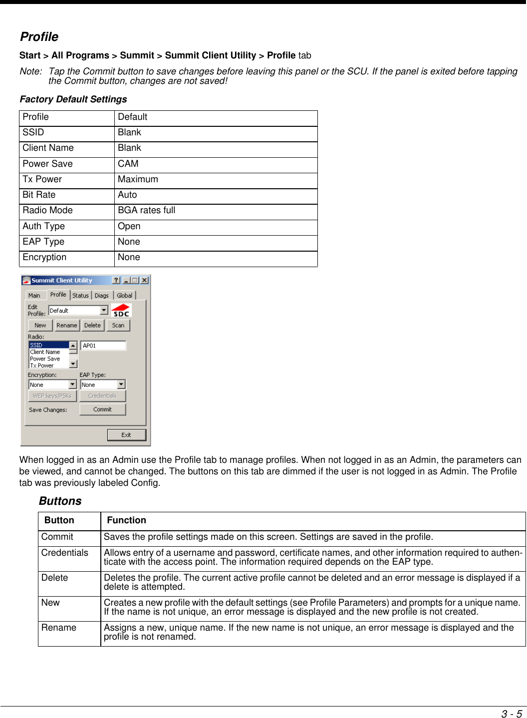
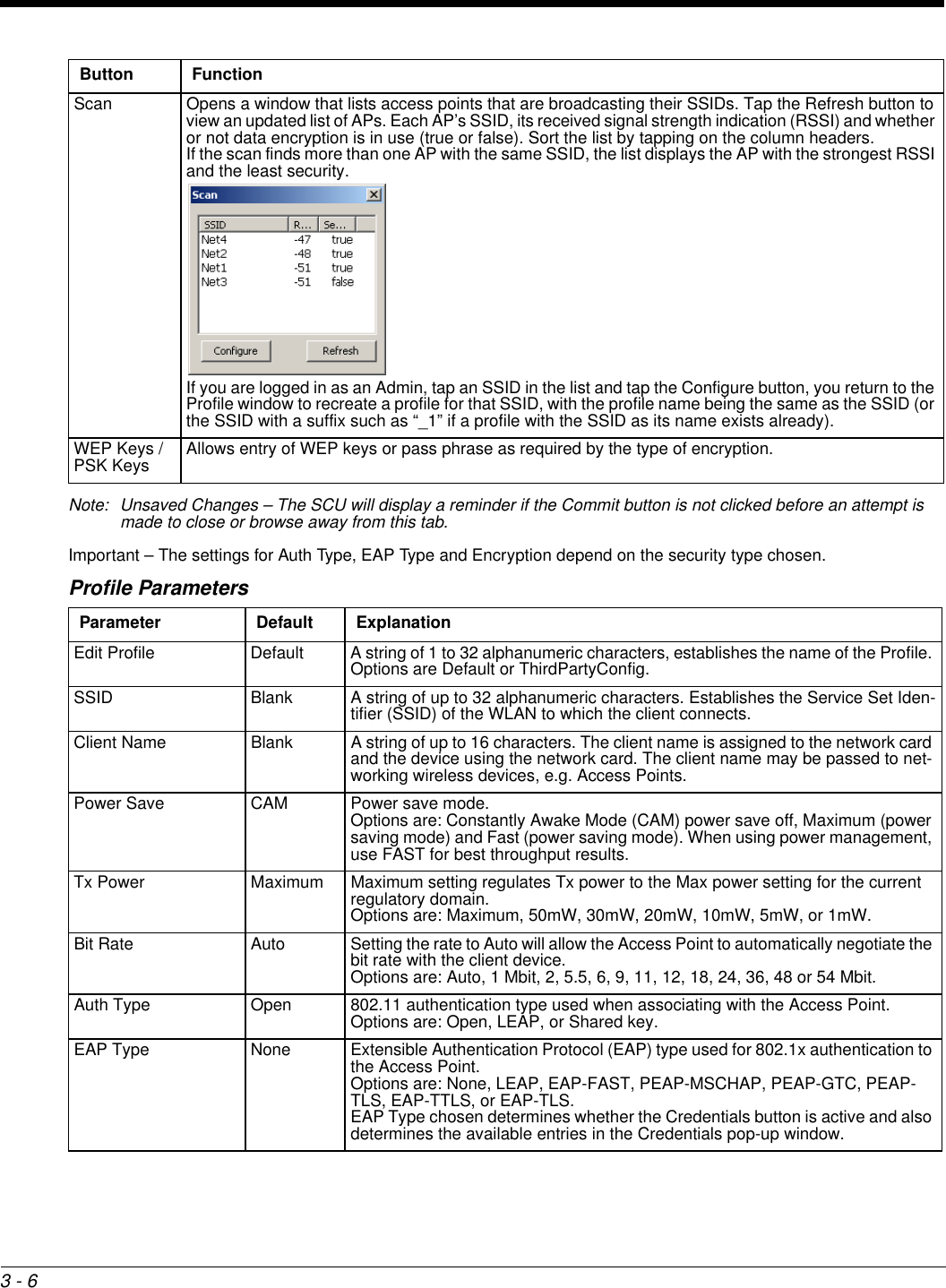
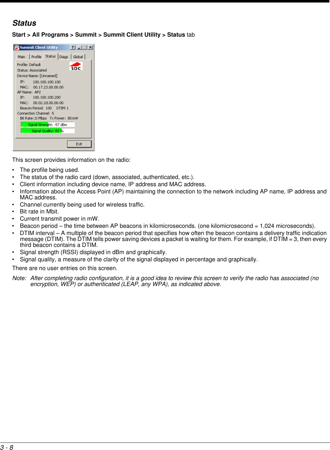
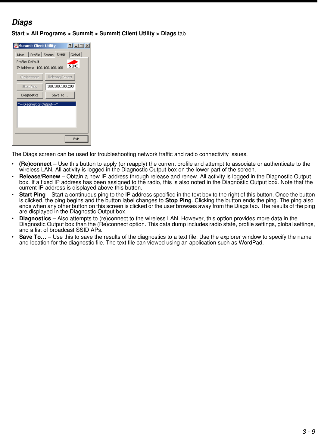
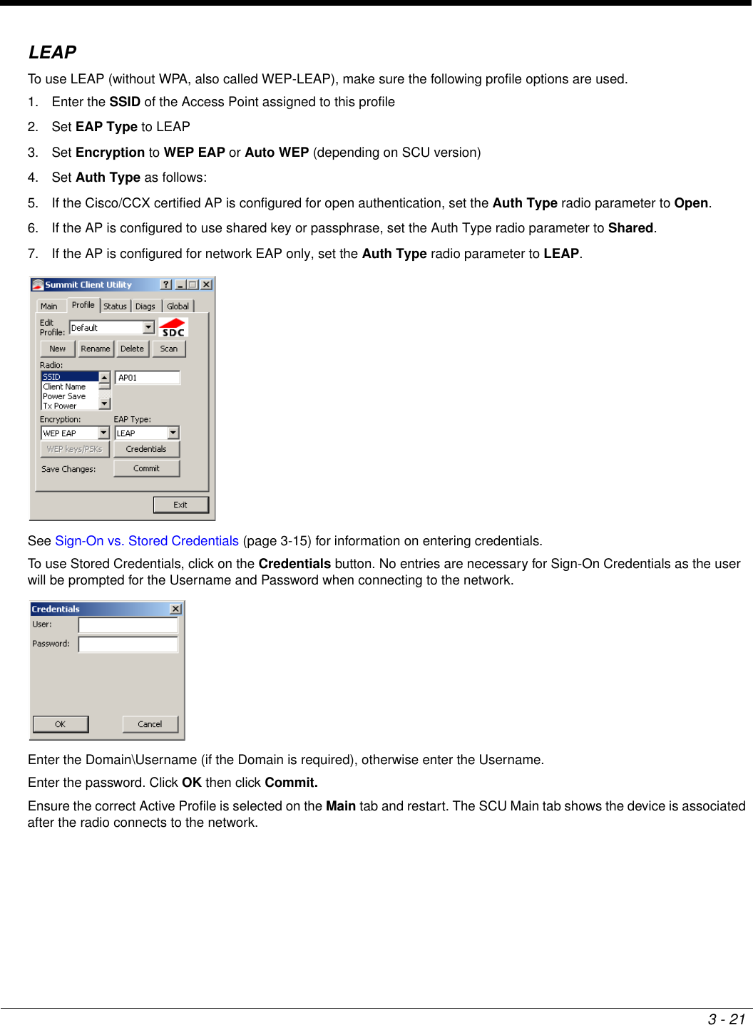
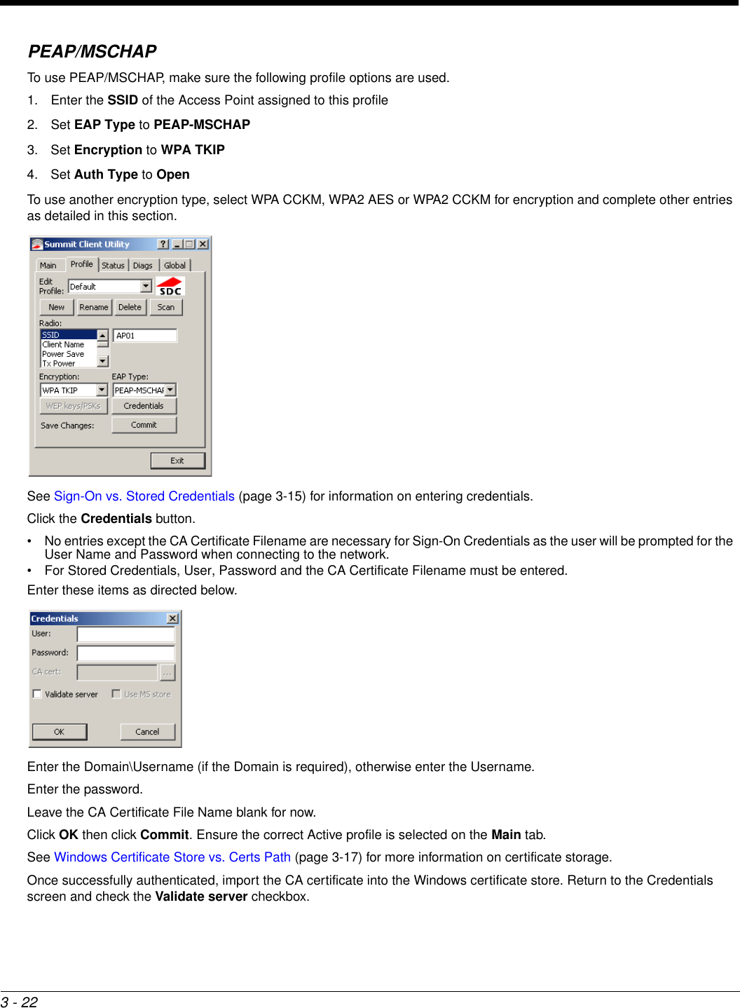
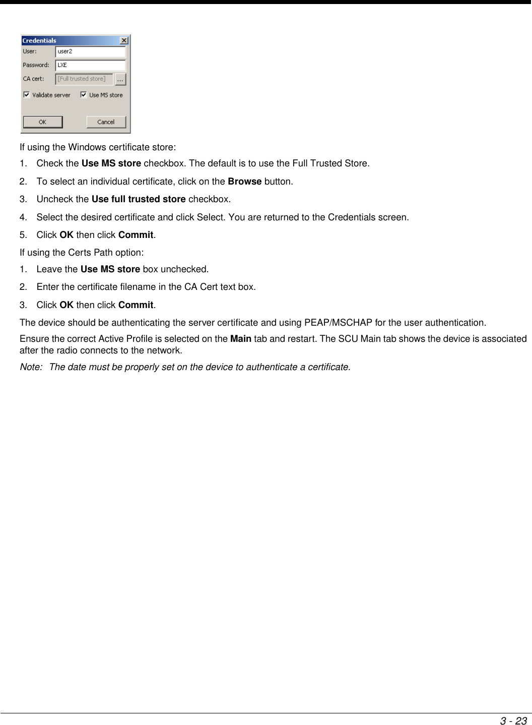
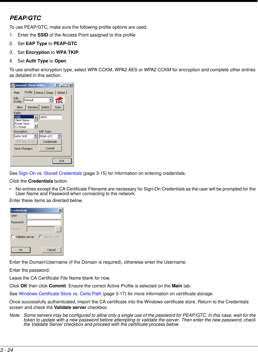
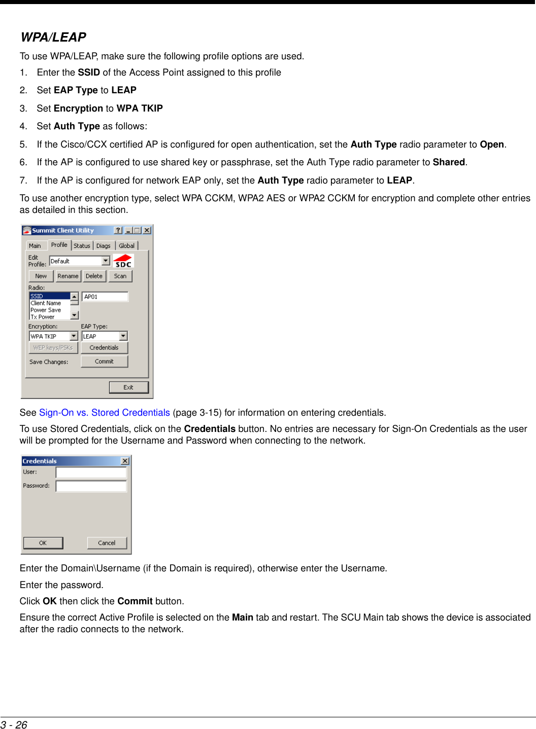
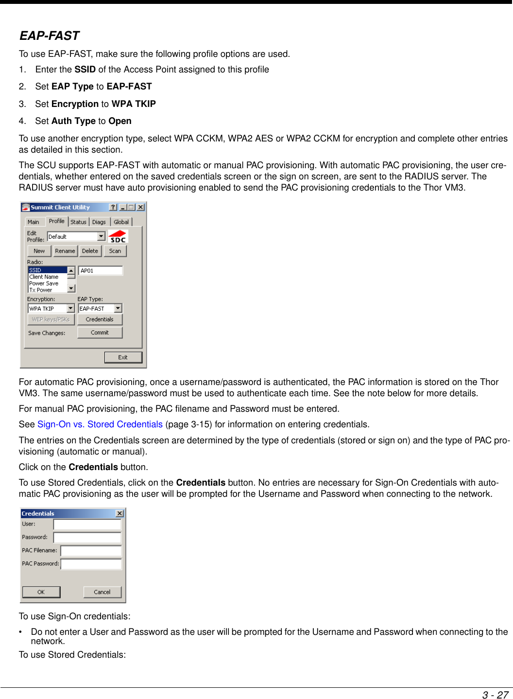
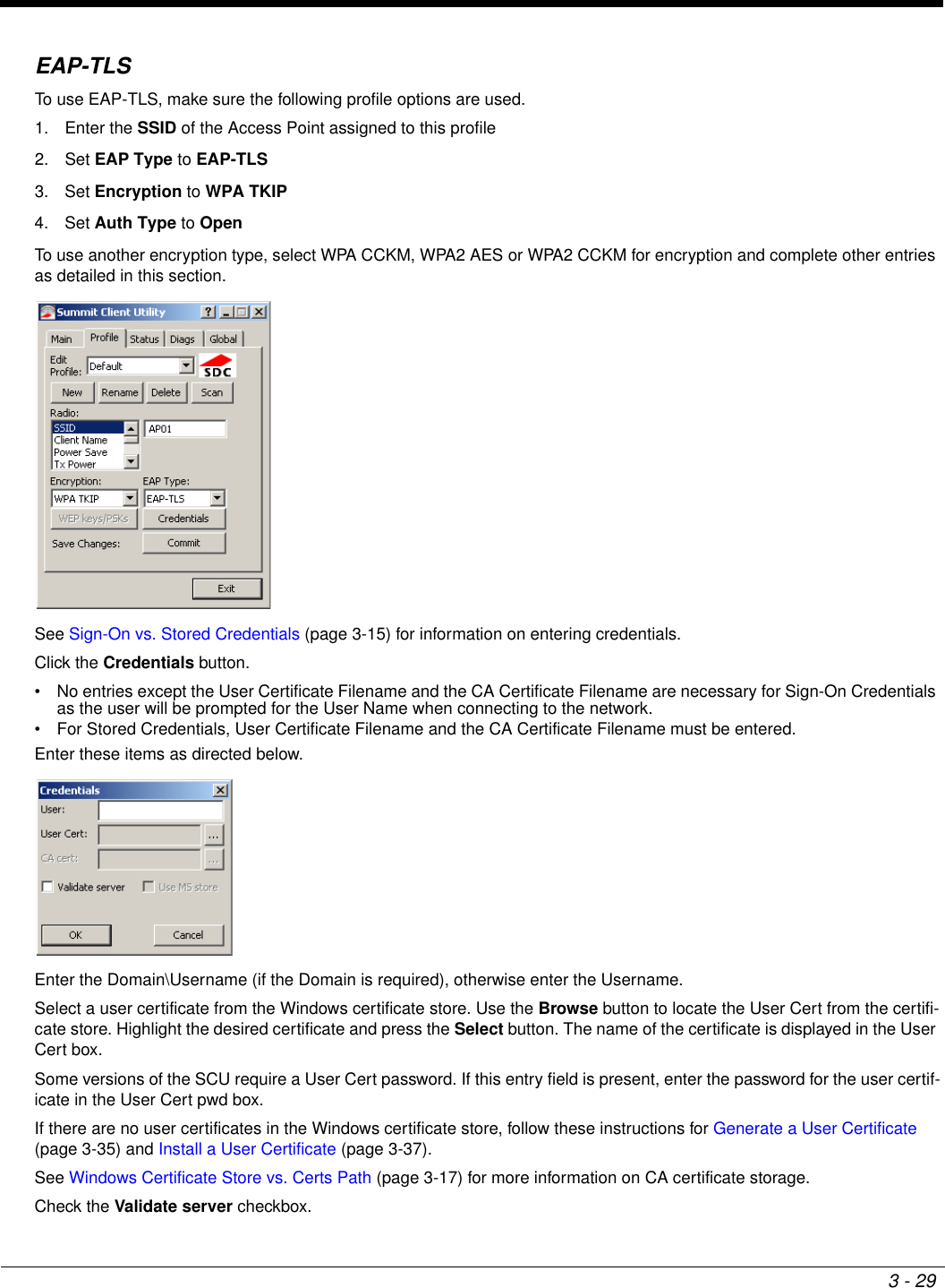
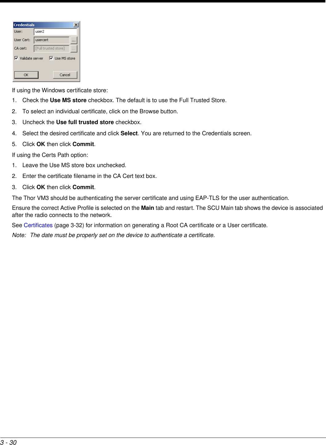
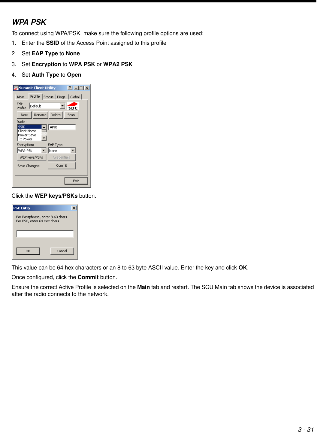
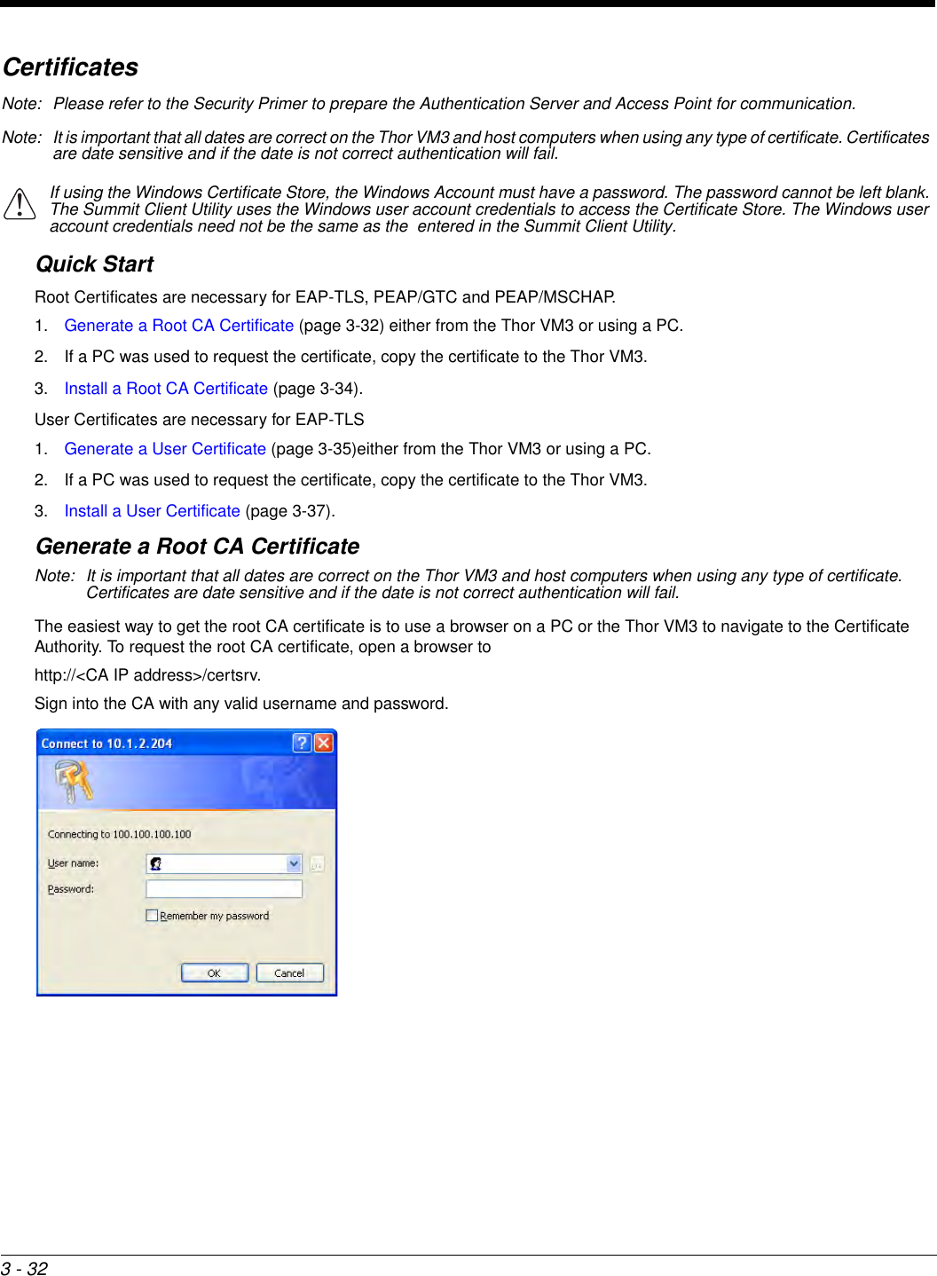
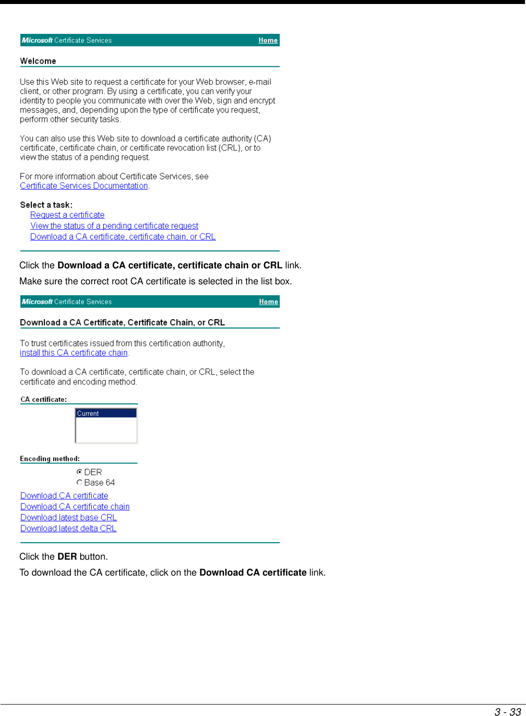
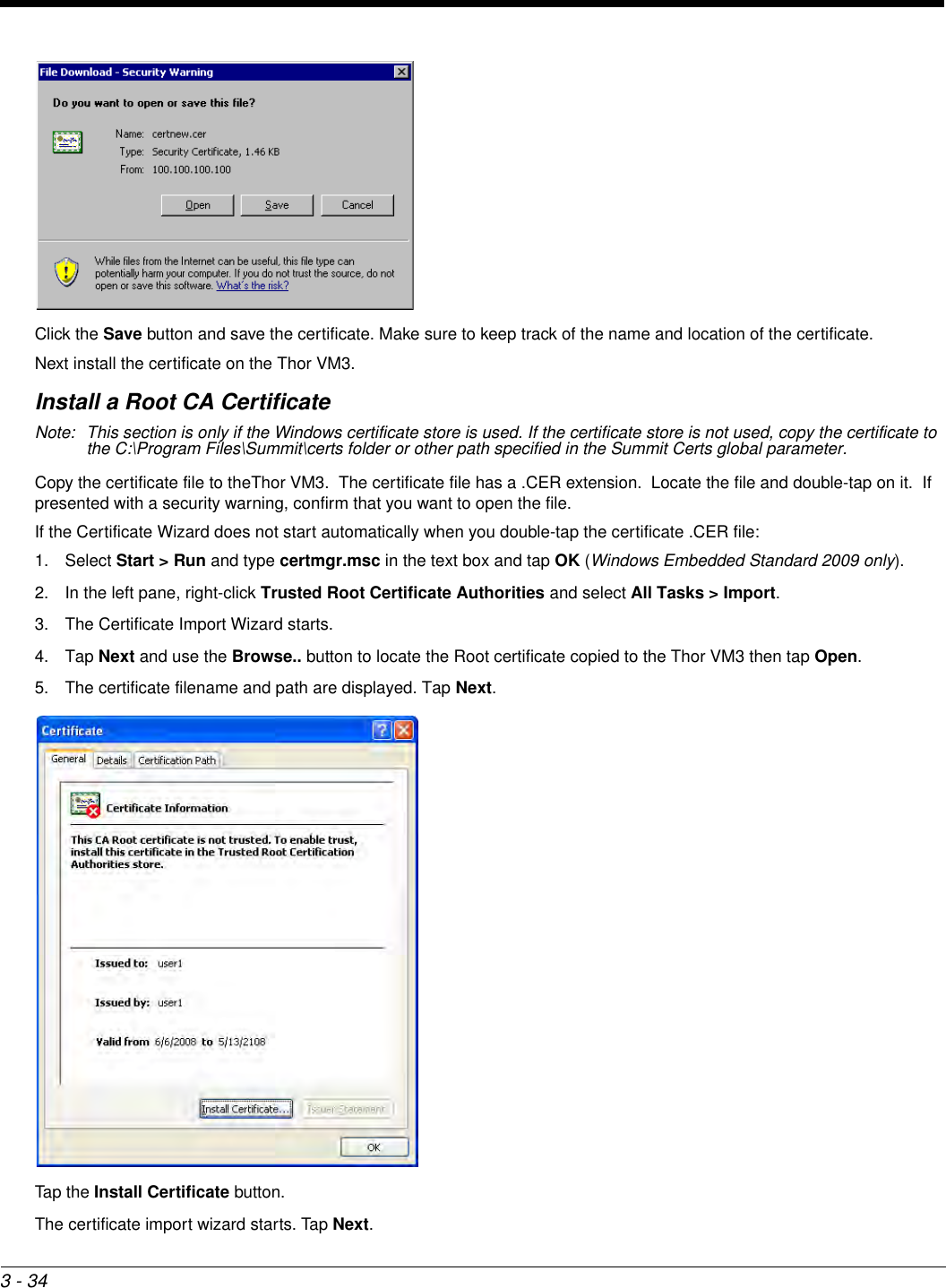
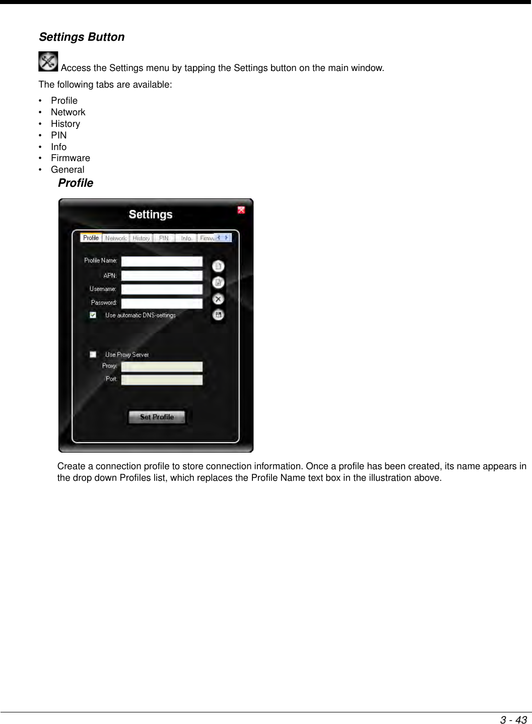
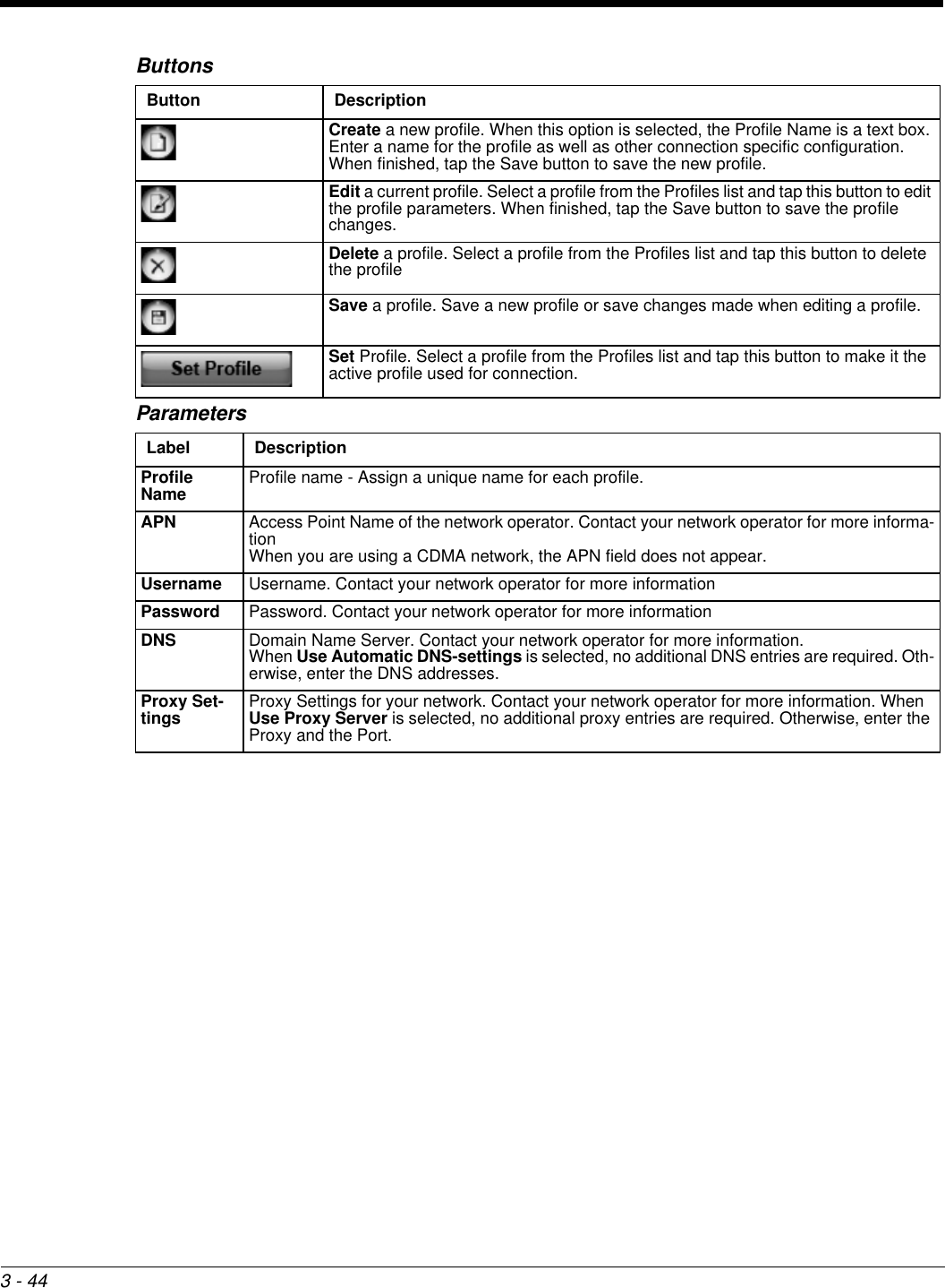
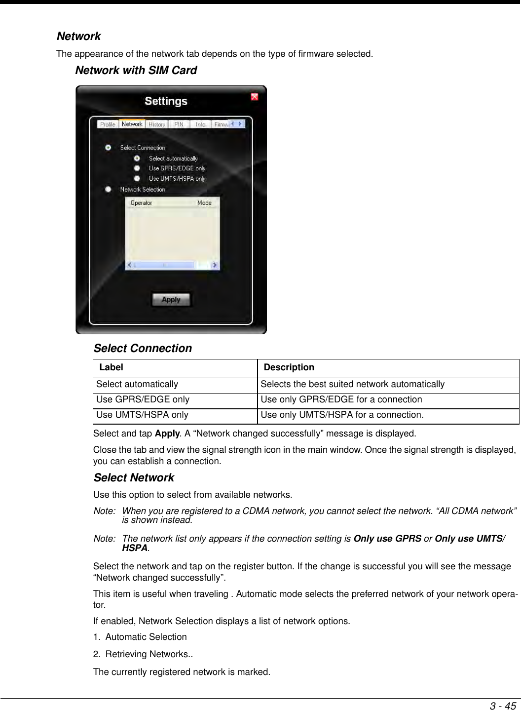
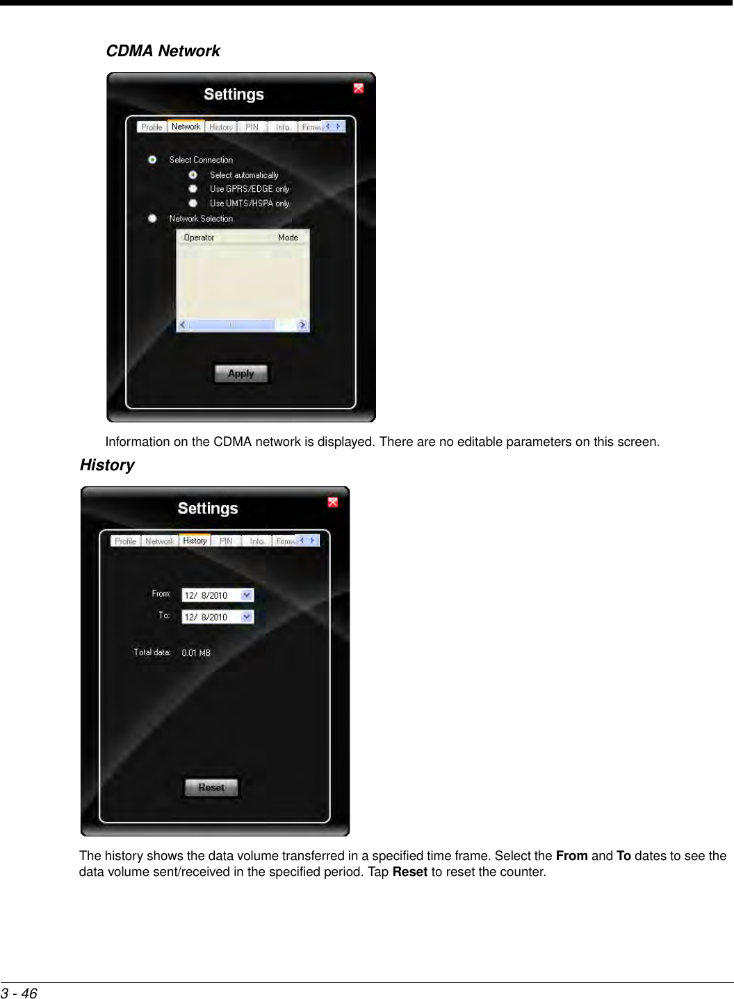
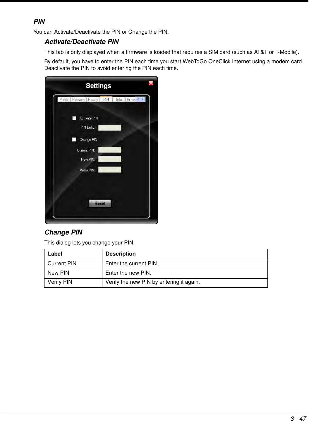
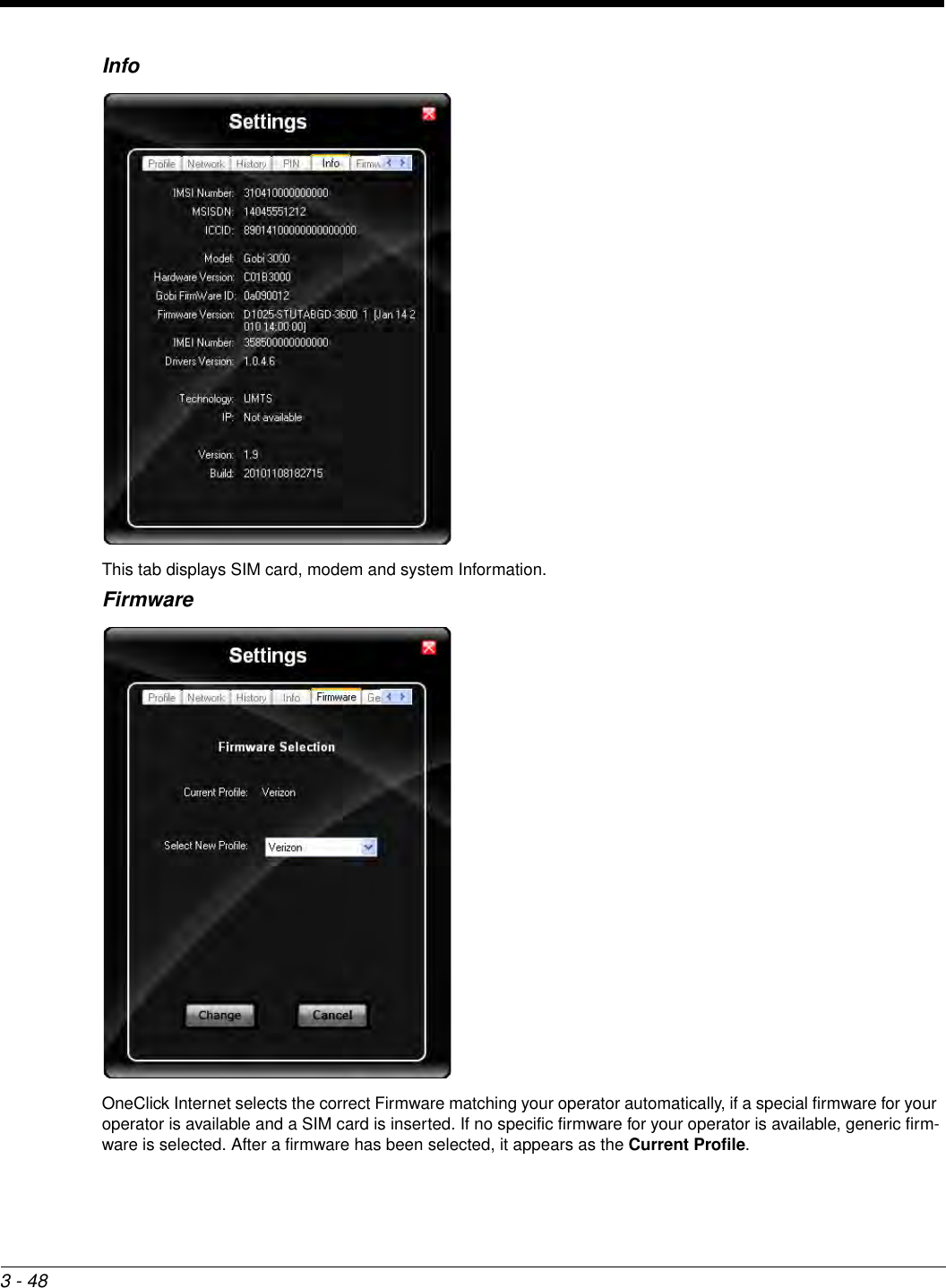
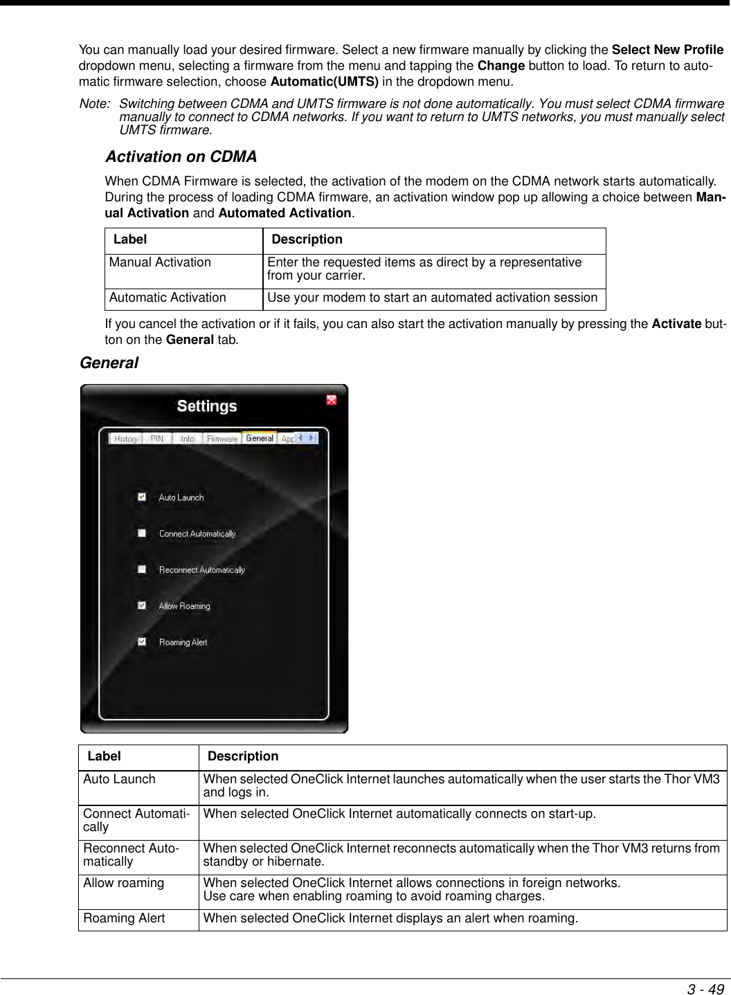
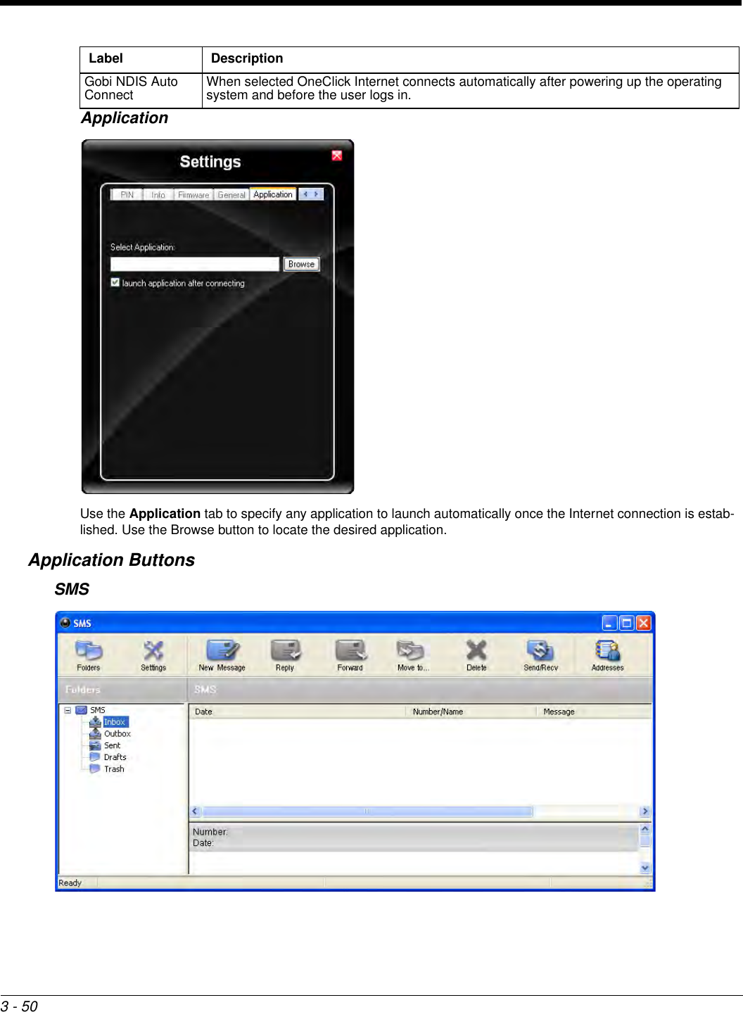
User Manual_VM3-W7-UG Rev (a)-2
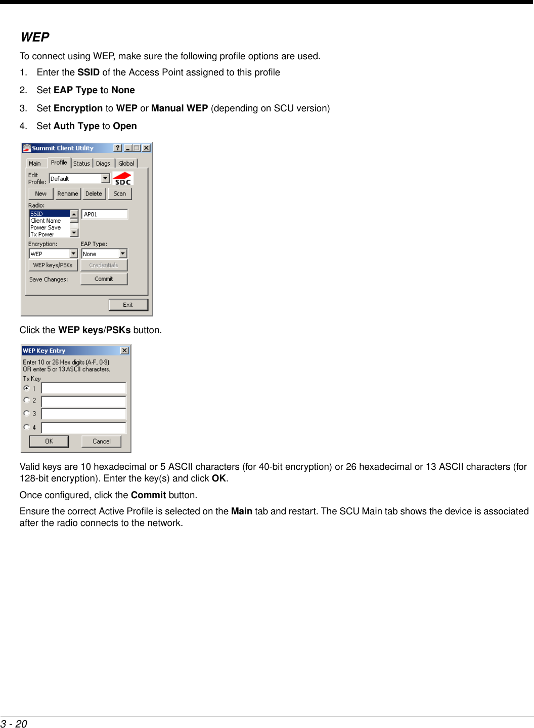
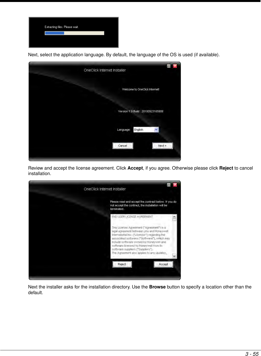
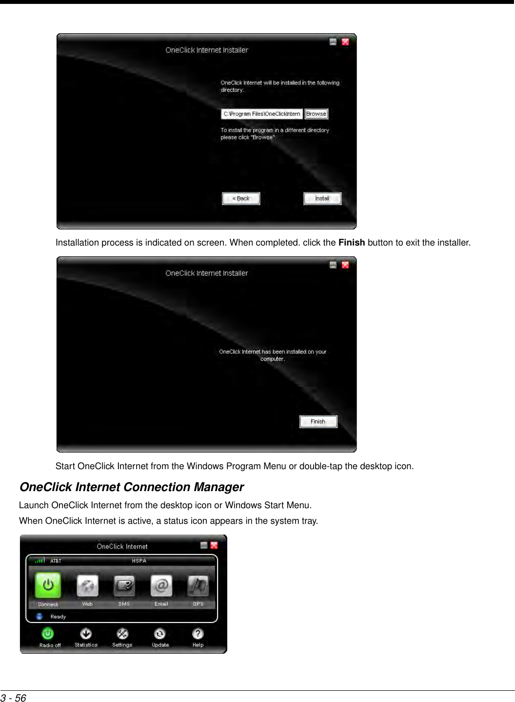
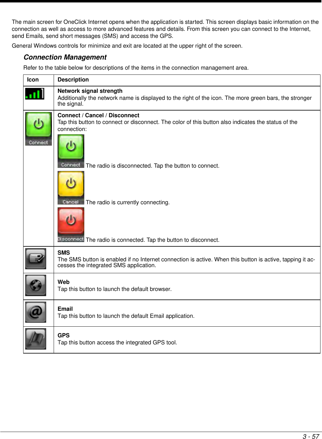
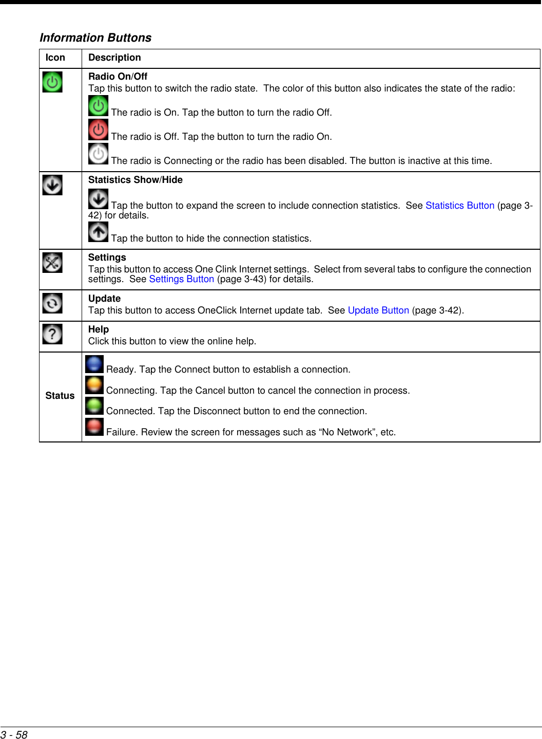
3 - 3MainStart > All Programs > Summit > Summit Client Utility > Main tabFactory Default SettingsThe Main tab displays information about the wireless client device including:• SCU (Summit Client Utility) version• Driver version• Radio Type (ABGN is an 802.11 a/b/g/n radio).• Regulatory Domain• Copyright Information can be accessed by tapping the About SCU button• Active Config profile / Active Profile name• Status of the client (Down, Associated, Authenticated, etc.).The Active Profile can be switched without logging in to Admin mode. Selecting a different profile from the drop down list does not require logging in to Administrator mode. The profile must already exist. Profiles can be created or edited after the Admin login password has been entered and accepted. When the profile named “ThirdPartyConfig” is chosen as the active profile, the Summit Client Utility passes control to Wire-less Manager for configuration of all client and security settings for the network module. The Disable Radio button can be used to disable the network card. Once disabled, the button label changes to Enable Radio. By default the radio is enabled.The Admin Login button provides access to editing wireless parameters. Profile and Global may only be edited after enter-ing the Admin Login password. The password is case-sensitive. Once logged in, the button label changes to Admin Logout. To logout, either tap the Admin Logout button or exit the SCU without tapping the Admin Logout button.Admin LoginTo login to Administrator mode, tap the Admin Login button.Once logged in, the button label changes to Admin Logout. The admin is automatically logged out when the SCU is exited. The Admin can either tap the Admin Logout button, or the OK button to logout. Admin Login SUMMITRadio EnabledActive Config/Profile DefaultRegulatory Domain FCC, ETSI or Worldwide
3 - 4Enter the Admin password (the default password is SUMMIT and is case sensitive) and tap OK. If the password is incorrect, an error message is displayed.The Administrator default password can be changed on the  tab.The end-user can:• Turn the radio on or off on the Main tab.• Select an active Profile on the Main tab.• View the current parameter settings for the profiles on the Profile tab.• View the global parameter settings on the Global tab.• View the current connection details on the Status tab.• View radio status, software versions and regulatory domain on the Main tab.• Access additional troubleshooting features on the Diags tab.After Admin Login, the end-user can also:• Create, edit, rename and delete profiles on the Profile tab.• Edit global parameters on the Global tab.• Enable/disable the Summit tray icon in the taskbar.
3 - 5ProfileStart > All Programs > Summit > Summit Client Utility > Profile tabNote: Tap the Commit button to save changes before leaving this panel or the SCU. If the panel is exited before tapping the Commit button, changes are not saved!Factory Default SettingsWhen logged in as an Admin use the Profile tab to manage profiles. When not logged in as an Admin, the parameters can be viewed, and cannot be changed. The buttons on this tab are dimmed if the user is not logged in as Admin. The Profile tab was previously labeled Config.ButtonsProfile DefaultSSID BlankClient Name BlankPower Save CAMTx Power MaximumBit Rate AutoRadio Mode BGA rates fullAuth Type OpenEAP Type NoneEncryption NoneButton FunctionCommit Saves the profile settings made on this screen. Settings are saved in the profile.Credentials Allows entry of a username and password, certificate names, and other information required to authen-ticate with the access point. The information required depends on the EAP type.Delete Deletes the profile. The current active profile cannot be deleted and an error message is displayed if a delete is attempted.New Creates a new profile with the default settings (see Profile Parameters) and prompts for a unique name. If the name is not unique, an error message is displayed and the new profile is not created.Rename Assigns a new, unique name. If the new name is not unique, an error message is displayed and the profile is not renamed.
3 - 6Note: Unsaved Changes – The SCU will display a reminder if the Commit button is not clicked before an attempt is made to close or browse away from this tab.Important – The settings for Auth Type, EAP Type and Encryption depend on the security type chosen. Profile ParametersScan Opens a window that lists access points that are broadcasting their SSIDs. Tap the Refresh button to view an updated list of APs. Each AP’s SSID, its received signal strength indication (RSSI) and whether or not data encryption is in use (true or false). Sort the list by tapping on the column headers.If the scan finds more than one AP with the same SSID, the list displays the AP with the strongest RSSI and the least security.If you are logged in as an Admin, tap an SSID in the list and tap the Configure button, you return to the Profile window to recreate a profile for that SSID, with the profile name being the same as the SSID (or the SSID with a suffix such as “_1” if a profile with the SSID as its name exists already).WEP Keys / PSK Keys Allows entry of WEP keys or pass phrase as required by the type of encryption.Parameter Default ExplanationEdit Profile Default A string of 1 to 32 alphanumeric characters, establishes the name of the Profile. Options are Default or ThirdPartyConfig.SSID Blank A string of up to 32 alphanumeric characters. Establishes the Service Set Iden-tifier (SSID) of the WLAN to which the client connects. Client Name Blank A string of up to 16 characters. The client name is assigned to the network card and the device using the network card. The client name may be passed to net-working wireless devices, e.g. Access Points.Power Save CAM Power save mode.Options are: Constantly Awake Mode (CAM) power save off, Maximum (power saving mode) and Fast (power saving mode). When using power management, use FAST for best throughput results.Tx Power Maximum Maximum setting regulates Tx power to the Max power setting for the current regulatory domain. Options are: Maximum, 50mW, 30mW, 20mW, 10mW, 5mW, or 1mW.Bit Rate Auto Setting the rate to Auto will allow the Access Point to automatically negotiate the bit rate with the client device. Options are: Auto, 1 Mbit, 2, 5.5, 6, 9, 11, 12, 18, 24, 36, 48 or 54 Mbit.Auth Type Open 802.11 authentication type used when associating with the Access Point. Options are: Open, LEAP, or Shared key.EAP Type None Extensible Authentication Protocol (EAP) type used for 802.1x authentication to the Access Point. Options are: None, LEAP, EAP-FAST, PEAP-MSCHAP, PEAP-GTC, PEAP-TLS, EAP-TTLS, or EAP-TLS. EAP Type chosen determines whether the Credentials button is active and also determines the available entries in the Credentials pop-up window.Button Function
3 - 7It is important the Radio Mode parameter correspond to the AP to which the device is to connect. For example, if this parameter is set to G rates only, the Thor VM3 may only connect to APs set for G rates and not those set for B and G rates.Encryption None Type of encryption to be used to protect transmitted data. Available options may vary by SCU version.Options are: None, WEP (or Manual WEP), WEP EAP (or Auto WEP), WPA PSK, WPA TKIP, WPA CCKM, WPA2 PSK, WPA2 AES, or WPA2 CCKM.CKIP is not supported in the Thor VM3.Note: The Encryption type chosen determines if the WEP Keys / PSK Keys button is active and also determines the available entries in the WEP or PSK pop-up window.Radio Mode BGA Rates Full  Specify 802.11a, 802.11b and/or 802.11g rates when communicating with the AP. The options displayed for this parameter depend on the type of radio in-stalled in the mobile device. Options:B rates only (1, 2, 5.5 and 11 Mbps)BG Rates Full (All B and G rates)G rates only (6, 9, 12, 18, 24, 36, 48 and 54 Mbps)BG optimized or BG subset (1, 2, 5.5, 6, 11, 24, 36 and 54 Mbps) A rates only (6, 9, 12, 18, 24, 36, 48 and 54 Mbps)ABG Rates Full (All A rates and all B and G rates with A rates preferred)BGA Rates Full (All B and G rates and all A rates with B and G rates preferred)Ad Hoc (when connecting to another client device instead of an AP)Default:BGA Rates FullParameter Default Explanation
3 - 8StatusStart > All Programs > Summit > Summit Client Utility > Status tabThis screen provides information on the radio:• The profile being used.• The status of the radio card (down, associated, authenticated, etc.).• Client information including device name, IP address and MAC address.• Information about the Access Point (AP) maintaining the connection to the network including AP name, IP address and MAC address.• Channel currently being used for wireless traffic.• Bit rate in Mbit.• Current transmit power in mW.• Beacon period – the time between AP beacons in kilomicroseconds. (one kilomicrosecond = 1,024 microseconds).• DTIM interval – A multiple of the beacon period that specifies how often the beacon contains a delivery traffic indication message (DTIM). The DTIM tells power saving devices a packet is waiting for them. For example, if DTIM = 3, then every third beacon contains a DTIM.• Signal strength (RSSI) displayed in dBm and graphically.• Signal quality, a measure of the clarity of the signal displayed in percentage and graphically.There are no user entries on this screen.Note: After completing radio configuration, it is a good idea to review this screen to verify the radio has associated (no encryption, WEP) or authenticated (LEAP, any WPA), as indicated above.
3 - 9DiagsStart > All Programs > Summit > Summit Client Utility > Diags tabThe Diags screen can be used for troubleshooting network traffic and radio connectivity issues.•(Re)connect – Use this button to apply (or reapply) the current profile and attempt to associate or authenticate to the wireless LAN. All activity is logged in the Diagnostic Output box on the lower part of the screen.•Release/Renew – Obtain a new IP address through release and renew. All activity is logged in the Diagnostic Output box. If a fixed IP address has been assigned to the radio, this is also noted in the Diagnostic Output box. Note that the current IP address is displayed above this button.•Start Ping – Start a continuous ping to the IP address specified in the text box to the right of this button. Once the button is clicked, the ping begins and the button label changes to Stop Ping. Clicking the button ends the ping. The ping also ends when any other button on this screen is clicked or the user browses away from the Diags tab. The results of the ping are displayed in the Diagnostic Output box.•Diagnostics – Also attempts to (re)connect to the wireless LAN. However, this option provides more data in the Diagnostic Output box than the (Re)connect option. This data dump includes radio state, profile settings, global settings, and a list of broadcast SSID APs.•Save To… – Use this to save the results of the diagnostics to a text file. Use the explorer window to specify the name and location for the diagnostic file. The text file can viewed using an application such as WordPad.
3 - 10GlobalStart > All Programs > Summit > Summit Client Utility > Global tabThe parameters on this panel can only be changed when an  with a password. The current values for the parameters can be viewed by the general user without requiring a password.Note: Tap the Commit button to save changes. If the panel is exited before tapping the Commit button, changes are not saved!Factory Default SettingsRoam Trigger -65 dBmRoam Delta 5 dBmRoam Period 10 sec.BG Channel Set Full DFS Channels OffDFS Scan Time 120 ms.Ad Hoc Channel 1Aggressive Scan OnCCX Features OptimizedWMM OnAuth Server Type 1TTLS Inner Method Auto-EAPPMK Caching StandardWAPI Off (dimmed)TX Diversity OnRX Diversity On Start on MainFrag Threshold 2346RTS Threshold 2347LED OffTray Icon On Hide Passwords OnAdmin Password SUMMIT (or blank)Auth Timeout 8 secondsCerts Path C:\Program Files\Summit\certsPing Payload 32 bytesPing Timeout 5000 msPing Delay ms 1000 msLogon Options Use SCU credentials
3 - 11Custom Parameter OptionThe parameter value is displayed as “Custom” when the operating system registry has been edited to set the Summit parameter to a value that is not available from the parameter’s drop down list. Selecting Custom from the drop down list has no effect. Selecting any other value from the drop down list will overwrite the “custom” value in the registry.Global ParametersParameter Default FunctionRoam Trigger -65 dBm If signal strength is less than this trigger value, the client looks for a dif-ferent Access Point with a stronger signal. Options are: -50 dBm, -55, -60, -65, -70, -75, -80, -85, -90 dBm or .Roam Delta 5 dBm The amount by which a different Access Point signal strength must ex-ceed the current Access Point signal strength before roaming to the dif-ferent Access Point is attempted. Options are: 5 dBm, 10, 15, 20, 25, 30, 35 dBm or Custom.Roam Period 10 sec. The amount of time, after association or a roam scan with no roam, that the radio collects Received Signal Strength Indication (RSSI) scan data before a roaming decision is made. Options are: 5 sec, 10, 15, 20, 25, 30, 35, 40, 45, 50, 55, 60 seconds or Custom.BG Channel Set Full Defines the 2.4GHz channels to be scanned for an AP when the radio is contemplating roaming. By specifying the channels to search, roaming time may be reduced over scanning all channels.Options are:Full (all channels)1,6,11 (the most commonly used channels)1,7,13 (for ETSI and TELEC radios only)or Custom.DFS Channels Off Support for 5GHZ 802.11a channels where support for DFS is required.Options are: On, Off, Optimized.Not supported (always off) in some releases.DFS Scan Time 120 ms. ABG radio only. The amount of time the radio will passively scan each DFS channel to see if it will receive a beacon. Recommended value is 1.5 times that of the AP's beacon period.Ad Hoc Channel  1 Use this parameter when the Radio Mode profile parameter is set to Ad Hoc.Specifies the channel to be used for an Ad Hoc connection to another cli-ent device. If a channel is selected that is not supported by the by the ra-dio, the default value is used.Options are:1 through 14 (the 2.4GHz channels) 36, 40, 44, 48 (the UNII-1 channels)
3 - 12Aggressive Scan  On When set to On and the current connection to an AP weakens, the radio aggressively scans for available APs.Aggressive scanning works with standard scanning (set through Roam Trigger, Roam Delta and Roam Period). Aggressive scanning should be set to On unless there is significant co-channel interference due to over-lapping APs on the same channel.Options are: On, OffCCX or CCX Features Optimized Use of Cisco Compatible Extensions (CCX) radio management and AP specified maximum transmit power features.Options are: Full - Use Cisco IE and CCX version number, support all CCX features. The option known as “On” in previous versions.Optimized –Use Cisco IE and CCX version number, support all CCX fea-tures except AP assisted roaming, AP specified maximum transmit pow-er and radio management.Off - Do not use Cisco IE and CCX version number.Cisco IE = Cisco Information Element.WMM On Use of Wi-Fi Multimedia extensions.Devices running Windows XP can change the default value. Devices run-ning all other OS cannot change the default value.Auth Server Type 1 Specifies the type of authentication server. Options are: Type 1 (ACS server) and Type 2 (non-ACS server)TTLS Inner Method Auto-EAP Authentication method used within the secure tunnel created by EAP-TTLS.Options are:AUTO-EAP (Any available EAP method), MSCHAPV2, MSCHAP, PAPCHAP, EAP-MSCHAPV2PMK Caching Standard Type of Pairwise Master Key (PMK) caching to use when WPA2 is in use. PMK caching is designed to speed up roaming between APs by al-lowing the client and the AP to cache the results of 802.1X authentica-tions, eliminating the need to communicate with the ACS server. Standard PMK is used when there are no controllers. The reauthentica-tion information is cached on the original AP. The client and the AP use the cached information to perform the four-way handshake to exchange keys. Opportunistic PMK (OPMK) is used when there are controllers. The reauthentication information cached on the controllers. The client and the controller behind the AP use the cached information to perform the four-way handshake to exchange keys.If the selected PMK caching method is not supported by the network in-frastructure, every roam requires full 802.11X authentication, including interaction with the ACS server.If the active profile is using WPA2 CCKM, the global PMK Caching set-ting is ignored and the client attempts to use CCKM.Options are: Standard, OPMKWAPI Off Default is Off and dimmed (cannot be changed).TX Diversity On How to handle antenna diversity when transmitting packets to the Access Point. Options are: Main only, and On.RX Diversity On Start on Main How to handle antenna diversity when receiving packets from the Access Point. Option is: On-start on MainThis parameter cannot be changed for some Summit radios.Frag Thresh 2346 If the packet size (in bytes) exceeds the specified number of bytes set in the fragment threshold, the packet is fragmented (sent as several pieces instead of as one block). Use a low setting in areas where communica-tion is poor or where there is a great deal of wireless interference. Options are: Any number between 256 bytes and 2346 bytes.Parameter Default Function
3 - 13Note: Tap the Commit button to save changes. If this panel is closed before tapping the Commit button, changes are not saved!Logon OptionsThere are two options available, a Single Signon (page 3-14) option which uses the Windows username and password as the credentials for 802.1x authentication and a Pre-Logon Connection (page 3-14) option which uses saved creden-tials for 802.1x authentication before Windows logon.RTS Thresh 2347 If the packet size exceeds the specified number of bytes set in the Re-quest to Send (RTS) threshold, an RTS is sent before sending the pack-et. A low RTS threshold setting can be useful in areas where many client devices are associating with the Access Point. This parameter cannot be changed.LED Off The LED on the wireless card is not visible to the user when the wireless card is installed in a sealed mobile device. Options are: On, Off. Tray Icon  On Determines if the Summit icon is displayed in the System tray.Options are: On, OffThe tray icon is not displayed when the Thor VM3 is running a Windows Embedded Standard 2009 operating system.Hide Password On When On, the Summit Config Utility masks passwords (characters on the screen are displayed as an *) as they are typed and when they are viewed. When Off, password characters are not masked.Options are: On, Off.Admin Password SUMMIT(or Blank) A string of up to 64 alphanumeric characters that must be entered when the Admin Login button is tapped. If Hide Password is On, the password is masked when typed in the Admin Password Entry dialog box. The password is case sensitive. This value is masked when the Admin is logged out.Options are: none.Auth Timeout  8 seconds Specifies the number of seconds the Summit software waits for an EAP authentication request to succeed or fail.If the authentication credentials are stored in the active profile and the authentication times out, the association fails. No error message or prompting for corrected credentials is displayed.If the authentication credentials are not stored in the active profile and the authentication times out, the user is again prompted to enter the cre-dentials.Options are: An integer from 3 to 60.Certs Path certificates A valid directory path, of up to 64 characters, where WPA Certificate Au-thority and User Certificates are stored on the mobile device when not using the Windows certificates store. Ensure the Windows folder path ex-ists before assigning the path in this parameter. See Certificates (page 3-32) for instructions on obtaining CA and User Certificates. This value is masked when the Admin is logged out.Options are: none.The complete path is C:\Program Files\Summit\certsPing Payload 32 bytes Maximum amount of data to be transmitted on a ping. Options are:  32 bytes, 64, 128, 256, 512, or 1024 bytes.Ping Timeout ms 5000 The amount of time, in milliseconds, that a device will be continuously pinged. The Stop Ping button can be tapped to end the ping process ahead of the ping timeout. Options are: Any number between 0 and 30000 ms.Ping Delay ms 1000 The amount of time, in milliseconds, between each ping after a Start Ping button tap. Options are: Any number between 0 and 30000 ms.Logon Options SCU Use SCU or Windows login credentials.Parameter Default Function
3 - 14If either option is enabled, the credentials entered here take precedence over any credentials entered on the profile tab.To use either option, select Logon Options from the Property list which activates the Logon Options button.Click the Logon Options button.Single SignonTo use the Single Signon option, select the checkbox for Use the Windows username and password when available. When the active profile is using LEAP, PEAP-MSCHAP, PEAP-GTC or EAP-FAST, the SCU ignores the username and password, if any, saved in the profile. Instead, the username and password used for Windows logon is used. Any certificates needed for authentication must still be specified in the profile.Click OK then click Commit.Pre-Logon ConnectionTo use the Pre_logon connection, select the checkbox for Enable pre-logon connection. This option is designed to be used when:• EAP authentication is required for a WLAN connection• Single Signon is configured, so the Windows username and password are used as credentials for EAP authentication• The WLAN connection needs to be established before the Windows login.Once this option is enabled, the Authentication delay and Association timeout values can be adjusted as nec-essary. Both values are specified in milliseconds (ms).The default authentication delay is 5000 ms and the valid range is 0 - 600,000 ms.The default association timeout is 10,000 ms and the valid range is 10,000 to 600,000 ms.Click on the Credentials button to enter the logon credentials.
3 - 15If using the Windows certificate store:1. Check the Use MS store checkbox. The default is to use the Full Trusted Store. 2. To select an individual certificate, click on the Browse button. 3. Uncheck the Use full trusted store checkbox. 4. Select the desired certificate and click Select. You are returned to the Credentials screen. 5. Click OK then click Commit.If using the Certs Path option:1. Leave the Use MS store box unchecked. 2. Enter the certificate filename in the CA Cert text box. 3. Click OK then click Commit.Sign-On vs. Stored CredentialsWhen using wireless security that requires a user name and password to be entered, the Summit Client Utility offers these choices:• The Username and Password may be entered on the Credentials screen. If this method is selected, anyone using the device can access the network.• The Username and Password are left blank on the Credentials screen. When the device attempts to connect to the network, a sign on screen is displayed. The user must enter the Username and Password at that time to authenticate.• When using Summit with the Thor VM3, there is an option on the Global tab to use the Windows user name and password to log on instead of any username and password stored in the profile.To Use Stored Credentials1. After completing the other entries in the profile, click on the Credentials button. 2. Enter the Username and Password on the Credentials screen and click the OK button.3. Click the Commit button.4. For LEAP and WPA/LEAP, configuration is complete.5. For PEAP-MSCHAP and PEAP-GTC, importing the CA certificate into the Windows certificate store is optional.6. For EAP-TLS, import the CA certificate into the Windows certificate store. Also import the User Certificate into the Windows certificate store.7. Access the Credentials screen again. Make sure the Validate server and Use MS store checkboxes are checked.8. The default is to use the entire certificate store for the CA certificate. Alternatively, use the Browse button next to the CA Cert (CA Certificate Filename) on the Credentials screen to select an individual certificate. 9. For EAP-TLS, also enter the User Cert (User Certificate filename) on the credentials screen by using the Browse button.10. If using EAP FAST and manual PAC provisioning, input the PAC filename and password.11. Click the OK button then the Commit button.
3 - 1612. If changes are made to the stored credentials, click Commit to save those changes before making any additional changes to the profile or global parameters.13. Verify the device is authenticated by reviewing the Status tab. When the device is property configured, the Status tab indicates the device is Authenticated and the method used.Note: See Configuring the Profile (page 3-18) for more details.Note: If invalid credentials are entered into the stored credentials, the authentication will fail. No error message is displayed. The user may or may not be prompted to enter valid credentials.To Use Sign On Screen1. After completing the other entries in the profile, click on the Credentials button. Leave the Username and Password blank. No entries are necessary on the Credentials screen for LEAP or LEAP/WPA.2. For PEAP-MSCHAP and PEAP-GTC, importing the CA certificate into the Windows certificate store is optional.3. For EAP-TLS, import the CA certificate into the Windows certificate store. Also import the User Certificate into the Windows certificate store.4. Access the Credentials screen again. Make sure the Validate server and Use MS store checkboxes are checked.5. The default is to use the entire certificate store for the CA certificate. Alternatively, use the Browse button next to the CA Cert (CA Certificate Filename) on the Credentials screen to select an individual certificate. 6. For EAP-TLS, also enter the User Cert (User Certificate filename) on the credentials screen by using the Browse button.7. Click the OK button then the Commit button.8. When the device attempts to connect to the network, a sign-on screen is displayed.9. Enter the Username and Password. Click the OK button.10. Verify the device is authenticated by reviewing the Status tab. When the device is property configured, the  indicates the device is Authenticated and the method used.11. The sign-on screen is displayed after a reboot. Note: See Configuring the Profile (page 3-18) for more details.If a user enters invalid credentials and clicks OK, the device associates but does not authenticate. The user is again prompted to enter credentials.If the user clicks the Cancel button, the device does not associate. The user is not prompted again for credentials until:• the device is rebooted,• the radio is disabled then enabled,•the Reconnect button on the  is clicked or• the profile is modified and the Commit button is clicked.To Use Windows Username and PasswordPlease see Logon Options (page 3-13) for information.
3 - 17Windows Certificate Store vs. Certs PathNote: It is important that all dates are correct on the Thor VM3 and host computers when using any type of certificate. Certificates are date sensitive and if the date is not correct authentication will fail.User CertificatesEAP-TLS authentication requires a user certificate. The user certificate must be stored in the Windows certificate store.• To generate the user certificate, see Generate a User Certificate (page 3-35).• To import the user certificate into the Windows certificate store, see Install a User Certificate (page 3-37).• A Root CA certificate is also needed. Refer to the section below.Root CA CertificatesRoot CA certificates are required for EAP/TLS, PEAP/GTC and PEAP/MSCHAP. Two options are offered for storing these certificates. They may be imported into the Windows certificate store or copied into the Certs Path directory.Certs Path1. See Generate a Root CA Certificate (page 3-32) and follow the instructions to download the Root Certificate to a PC.2. Copy the certificate to specified directory on the mobile device. The default location for Certs Path is C:\Program Files\Summit\certs. A different location may be specified by using the Certs Path global variable. 3. When completing the Credentials screen for the desired authentication, do not check the Use MS store checkbox after checking the Validate server checkbox.4. Enter the certificate name in the CA Cert text box.5. Click OK to exit the Credentials screen and then Commit to save the profile changes.Windows Certificate Store1. See Generate a Root CA Certificate (page 3-32) and follow the instructions to download the Root Certificate to a PC.2. To import the certificate into the Windows store, See Install a Root CA Certificate (page 3-34).3. When completing the Credentials screen for the desired authentication, be sure to check the Use MS store check-box after checking the Validate server checkbox.4. The default is to use all certificates in the store. If this is OK, skip to the last step.5. Otherwise, to select a specific certificate click on the Browse (…) button. If using the Windows Certificate Store, the Windows Account must have a password. The password cannot be left blank. The Summit Client Utility uses the Windows user account credentials to access the Certificate Store. The Windows user account credentials need not be the same as the credentials entered in the Summit Client Utility.!
3 - 186. Uncheck the Use full trusted store checkbox. 7. Select the desired certificate and click the Select button to return the selected certificate to the CA Cert text box.8. Click OK to exit the Credentials screen and then Commit to save the profile changes.Configuring the ProfileUse the instructions in this section to complete the entries on the Profile tab according to the type of wireless security used by your network. The instructions that follow are the minimum required to successfully connect to a network. Your system may require more parameters than are listed in these instructions. Please see your system administrator for complete information about your network and its wireless security requirements.To begin the configuration process:• On the Main click the Admin Login button and enter the password.• If using a single profile, edit the default profile with the parameters for your network. Select the Default profile from the pull-down menu.• Make any desired parameter changes as described in the applicable following section determined by network security type and click the Commit button to save the changes.IMPORTANT – Remember to click the Commit button after making changes to ensure the changes are saved. Many versions of the SCU display a reminder if the Commit button is not clicked before an attempt is made to close or browse away from the tab in focus if there are unsaved changes. If changes are made to the stored credentials, click Commit to save those changes first before making any additional changes.
3 - 19No SecurityTo connect to a wireless network with no security, make sure the following profile options are used.1. Enter the SSID of the Access Point assigned to this profile2. Set EAP Type to None3. Set Encryption to None4. Set Auth Type to OpenOnce configured, click the Commit button.Ensure the correct Active Profile is selected on the Main tab and restart. The SCU Main tab shows the device is associated after the radio connects to the network.
3 - 20WEPTo connect using WEP, make sure the following profile options are used.1. Enter the SSID of the Access Point assigned to this profile2. Set EAP Type to None3. Set Encryption to WEP or Manual WEP (depending on SCU version)4. Set Auth Type to OpenClick the WEP keys/PSKs button.Valid keys are 10 hexadecimal or 5 ASCII characters (for 40-bit encryption) or 26 hexadecimal or 13 ASCII characters (for 128-bit encryption). Enter the key(s) and click OK.Once configured, click the Commit button. Ensure the correct Active Profile is selected on the Main tab and restart. The SCU Main tab shows the device is associated after the radio connects to the network.
3 - 21LEAPTo use LEAP (without WPA, also called WEP-LEAP), make sure the following profile options are used.1. Enter the SSID of the Access Point assigned to this profile2. Set EAP Type to LEAP3. Set Encryption to WEP EAP or Auto WEP (depending on SCU version)4. Set Auth Type as follows:5. If the Cisco/CCX certified AP is configured for open authentication, set the Auth Type radio parameter to Open.6. If the AP is configured to use shared key or passphrase, set the Auth Type radio parameter to Shared.7. If the AP is configured for network EAP only, set the Auth Type radio parameter to LEAP.See Sign-On vs. Stored Credentials (page 3-15) for information on entering credentials.To use Stored Credentials, click on the Credentials button. No entries are necessary for Sign-On Credentials as the user will be prompted for the Username and Password when connecting to the network. Enter the Domain\Username (if the Domain is required), otherwise enter the Username.Enter the password. Click OK then click Commit.Ensure the correct Active Profile is selected on the Main tab and restart. The SCU Main tab shows the device is associated after the radio connects to the network.
3 - 22PEAP/MSCHAPTo use PEAP/MSCHAP, make sure the following profile options are used.1. Enter the SSID of the Access Point assigned to this profile2. Set EAP Type to PEAP-MSCHAP3. Set Encryption to WPA TKIP4. Set Auth Type to OpenTo use another encryption type, select WPA CCKM, WPA2 AES or WPA2 CCKM for encryption and complete other entries as detailed in this section.See Sign-On vs. Stored Credentials (page 3-15) for information on entering credentials.Click the Credentials button.• No entries except the CA Certificate Filename are necessary for Sign-On Credentials as the user will be prompted for the User Name and Password when connecting to the network.• For Stored Credentials, User, Password and the CA Certificate Filename must be entered.Enter these items as directed below.Enter the Domain\Username (if the Domain is required), otherwise enter the Username.Enter the password.Leave the CA Certificate File Name blank for now.Click OK then click Commit. Ensure the correct Active profile is selected on the Main tab.See Windows Certificate Store vs. Certs Path (page 3-17) for more information on certificate storage.Once successfully authenticated, import the CA certificate into the Windows certificate store. Return to the Credentials screen and check the Validate server checkbox.
3 - 23If using the Windows certificate store:1. Check the Use MS store checkbox. The default is to use the Full Trusted Store. 2. To select an individual certificate, click on the Browse button.3. Uncheck the Use full trusted store checkbox.4. Select the desired certificate and click Select. You are returned to the Credentials screen.5. Click OK then click Commit.If using the Certs Path option:1. Leave the Use MS store box unchecked.2. Enter the certificate filename in the CA Cert text box.3. Click OK then click Commit.The device should be authenticating the server certificate and using PEAP/MSCHAP for the user authentication. Ensure the correct Active Profile is selected on the Main tab and restart. The SCU Main tab shows the device is associated after the radio connects to the network.Note: The date must be properly set on the device to authenticate a certificate.
3 - 24PEAP/GTCTo use PEAP/GTC, make sure the following profile options are used.1. Enter the SSID of the Access Point assigned to this profile2. Set EAP Type to PEAP-GTC3. Set Encryption to WPA TKIP4. Set Auth Type to OpenTo use another encryption type, select WPA CCKM, WPA2 AES or WPA2 CCKM for encryption and complete other entries as detailed in this section.See Sign-On vs. Stored Credentials (page 3-15) for information on entering credentials.Click the Credentials button.• No entries except the CA Certificate Filename are necessary for Sign-On Credentials as the user will be prompted for the User Name and Password when connecting to the network. Enter these items as directed below.Enter the Domain\Username (if the Domain is required), otherwise enter the Username.Enter the password.Leave the CA Certificate File Name blank for now.Click OK then click Commit. Ensure the correct Active Profile is selected on the Main tab.See Windows Certificate Store vs. Certs Path (page 3-17) for more information on certificate storage.Once successfully authenticated, import the CA certificate into the Windows certificate store. Return to the Credentials screen and check the Validate server checkbox. Note: Some servers may be configured to allow only a single use of the password for PEAP/GTC. In this case, wait for the token to update with a new password before attempting to validate the server. Then enter the new password, check the Validate Server checkbox and proceed with the certificate process below.
3 - 25If using the Windows certificate store:1. Check the Use MS store checkbox. The default is to use the Full Trusted Store. 2. To select an individual certificate, click on the Browse button.3. Uncheck the Use full trusted store checkbox.4. Select the desired certificate and click Select. You are returned to the Credentials screen.5. Click OK then click Commit.If using the Certs Path option:1. Leave the Use MS store box unchecked.2. Enter the certificate filename in the CA Cert text box.3. Click OK then click Commit.The device should be authenticating the server certificate and using PEAP/GTC for the user authentication. Ensure the correct Active Profile is selected on the Main tab and restart. The SCU Main tab shows the device is associated after the radio connects to the network.Note: The date must be properly set on the device to authenticate a certificate.
3 - 26WPA/LEAPTo use WPA/LEAP, make sure the following profile options are used.1. Enter the SSID of the Access Point assigned to this profile2. Set EAP Type to LEAP3. Set Encryption to WPA TKIP4. Set Auth Type as follows:5. If the Cisco/CCX certified AP is configured for open authentication, set the Auth Type radio parameter to Open.6. If the AP is configured to use shared key or passphrase, set the Auth Type radio parameter to Shared.7. If the AP is configured for network EAP only, set the Auth Type radio parameter to LEAP.To use another encryption type, select WPA CCKM, WPA2 AES or WPA2 CCKM for encryption and complete other entries as detailed in this section.See Sign-On vs. Stored Credentials (page 3-15) for information on entering credentials.To use Stored Credentials, click on the Credentials button. No entries are necessary for Sign-On Credentials as the user will be prompted for the Username and Password when connecting to the network. Enter the Domain\Username (if the Domain is required), otherwise enter the Username.Enter the password.Click OK then click the Commit button. Ensure the correct Active Profile is selected on the Main tab and restart. The SCU Main tab shows the device is associated after the radio connects to the network.
3 - 27EAP-FASTTo use EAP-FAST, make sure the following profile options are used.1. Enter the SSID of the Access Point assigned to this profile2. Set EAP Type to EAP-FAST3. Set Encryption to WPA TKIP4. Set Auth Type to OpenTo use another encryption type, select WPA CCKM, WPA2 AES or WPA2 CCKM for encryption and complete other entries as detailed in this section.The SCU supports EAP-FAST with automatic or manual PAC provisioning. With automatic PAC provisioning, the user cre-dentials, whether entered on the saved credentials screen or the sign on screen, are sent to the RADIUS server. The RADIUS server must have auto provisioning enabled to send the PAC provisioning credentials to the Thor VM3.For automatic PAC provisioning, once a username/password is authenticated, the PAC information is stored on the Thor VM3. The same username/password must be used to authenticate each time. See the note below for more details.For manual PAC provisioning, the PAC filename and Password must be entered.See Sign-On vs. Stored Credentials (page 3-15) for information on entering credentials.The entries on the Credentials screen are determined by the type of credentials (stored or sign on) and the type of PAC pro-visioning (automatic or manual).Click on the Credentials button.To use Stored Credentials, click on the Credentials button. No entries are necessary for Sign-On Credentials with auto-matic PAC provisioning as the user will be prompted for the Username and Password when connecting to the network. To use Sign-On credentials:• Do not enter a User and Password as the user will be prompted for the Username and Password when connecting to the network.To use Stored Credentials:
3 - 28• Enter the Domain\Username (if the Domain is required), otherwise enter the Username. • Enter the password.To use Automatic PAC Provisioning:• No additional entries are required.To use manual PAC Provisioning:• Enter the PAC Filename and PAC Password.• The PAC file must be copied to the directory specified in the Certs Path global variable. The PAC file must not be read only.Ensure the correct Active Profile is selected on the Main tab and restart. The SCU Main tab shows the device is associated after the radio connects to the network.Note: When using Automatic PAC Provisioning, once authenticated, there is a file stored in the C:\Program Files\Summit\certs directory with the PAC credentials. If the username is changed, that file must be deleted. The filename is autoP.00.pac.
3 - 29EAP-TLSTo use EAP-TLS, make sure the following profile options are used.1. Enter the SSID of the Access Point assigned to this profile2. Set EAP Type to EAP-TLS3. Set Encryption to WPA TKIP4. Set Auth Type to OpenTo use another encryption type, select WPA CCKM, WPA2 AES or WPA2 CCKM for encryption and complete other entries as detailed in this section.See Sign-On vs. Stored Credentials (page 3-15) for information on entering credentials.Click the Credentials button.• No entries except the User Certificate Filename and the CA Certificate Filename are necessary for Sign-On Credentials as the user will be prompted for the User Name when connecting to the network. • For Stored Credentials, User Certificate Filename and the CA Certificate Filename must be entered.Enter these items as directed below.Enter the Domain\Username (if the Domain is required), otherwise enter the Username.Select a user certificate from the Windows certificate store. Use the Browse button to locate the User Cert from the certifi-cate store. Highlight the desired certificate and press the Select button. The name of the certificate is displayed in the User Cert box.Some versions of the SCU require a User Cert password. If this entry field is present, enter the password for the user certif-icate in the User Cert pwd box.If there are no user certificates in the Windows certificate store, follow these instructions for Generate a User Certificate (page 3-35) and Install a User Certificate (page 3-37).See Windows Certificate Store vs. Certs Path (page 3-17) for more information on CA certificate storage.Check the Validate server checkbox.
3 - 30If using the Windows certificate store:1. Check the Use MS store checkbox. The default is to use the Full Trusted Store. 2. To select an individual certificate, click on the Browse button.3. Uncheck the Use full trusted store checkbox.4. Select the desired certificate and click Select. You are returned to the Credentials screen.5. Click OK then click Commit.If using the Certs Path option:1. Leave the Use MS store box unchecked.2. Enter the certificate filename in the CA Cert text box.3. Click OK then click Commit.The Thor VM3 should be authenticating the server certificate and using EAP-TLS for the user authentication. Ensure the correct Active Profile is selected on the Main tab and restart. The SCU Main tab shows the device is associated after the radio connects to the network.See Certificates (page 3-32) for information on generating a Root CA certificate or a User certificate.Note: The date must be properly set on the device to authenticate a certificate.
3 - 31WPA PSKTo connect using WPA/PSK, make sure the following profile options are used:1. Enter the SSID of the Access Point assigned to this profile2. Set EAP Type to None3. Set Encryption to WPA PSK or WPA2 PSK4. Set Auth Type to OpenClick the WEP keys/PSKs button.This value can be 64 hex characters or an 8 to 63 byte ASCII value. Enter the key and click OK.Once configured, click the Commit button.Ensure the correct Active Profile is selected on the Main tab and restart. The SCU Main tab shows the device is associated after the radio connects to the network.
3 - 32CertificatesNote: Please refer to the Security Primer to prepare the Authentication Server and Access Point for communication.Note: It is important that all dates are correct on the Thor VM3 and host computers when using any type of certificate. Certificates are date sensitive and if the date is not correct authentication will fail.Quick StartRoot Certificates are necessary for EAP-TLS, PEAP/GTC and PEAP/MSCHAP.1. Generate a Root CA Certificate (page 3-32) either from the Thor VM3 or using a PC.2. If a PC was used to request the certificate, copy the certificate to the Thor VM3.3. Install a Root CA Certificate (page 3-34).User Certificates are necessary for EAP-TLS1. Generate a User Certificate (page 3-35)either from the Thor VM3 or using a PC.2. If a PC was used to request the certificate, copy the certificate to the Thor VM3.3. Install a User Certificate (page 3-37).Generate a Root CA CertificateNote: It is important that all dates are correct on the Thor VM3 and host computers when using any type of certificate. Certificates are date sensitive and if the date is not correct authentication will fail.The easiest way to get the root CA certificate is to use a browser on a PC or the Thor VM3 to navigate to the Certificate Authority. To request the root CA certificate, open a browser to http://<CA IP address>/certsrv. Sign into the CA with any valid username and password.If using the Windows Certificate Store, the Windows Account must have a password. The password cannot be left blank. The Summit Client Utility uses the Windows user account credentials to access the Certificate Store. The Windows user account credentials need not be the same as the  entered in the Summit Client Utility.!
3 - 33Click the Download a CA certificate, certificate chain or CRL link. Make sure the correct root CA certificate is selected in the list box.Click the DER button.To download the CA certificate, click on the Download CA certificate link.
3 - 34Click the Save button and save the certificate. Make sure to keep track of the name and location of the certificate.Next install the certificate on the Thor VM3.Install a Root CA CertificateNote: This section is only if the Windows certificate store is used. If the certificate store is not used, copy the certificate to the C:\Program Files\Summit\certs folder or other path specified in the Summit Certs global parameter.Copy the certificate file to theThor VM3.  The certificate file has a .CER extension.  Locate the file and double-tap on it.  If presented with a security warning, confirm that you want to open the file.If the Certificate Wizard does not start automatically when you double-tap the certificate .CER file:1. Select Start > Run and type certmgr.msc in the text box and tap OK (Windows Embedded Standard 2009 only).2. In the left pane, right-click Trusted Root Certificate Authorities and select All Tasks > Import.3. The Certificate Import Wizard starts.4. Tap Next and use the Browse.. button to locate the Root certificate copied to the Thor VM3 then tap Open.5. The certificate filename and path are displayed. Tap Next.Tap the Install Certificate button.The certificate import wizard starts. Tap Next.
3 - 35Generate a User CertificateThe easiest way to get the user certificate is to use the browser on the Thor VM3 or a PC to navigate to the Certificate Authority. To request the user certificate, open a browser to http://<CA IP address>/certsrv. Sign into the CA with the username and password of the person who will be logging into the mobile device.This process saves a user certificate file. There is no separate private key file as used on Windows CE devices.Click the Request a certificate link. Click on the User Certificate link.
3 - 36Click on the Submit button. if there is a message box asking if you want to confirm the request, click Yes.The User Certificate is issued.Install the user certificate on the requesting computer by clicking the Install this certificate link. If the requesting computer is the Thor VM3, then the process is finished. otherwise, export the certificate as described below.Exporting a User CertificateSelect Tools > Internet Options > Content and click the Certificates button.Make sure the Personal tab is selected. Highlight the certificate and click the Export button.The Certificate Export Wizard is startedSelect Yes, export the private key and click Next.
3 - 37Click Finish. and OK to close the Successful Export message.Locate the User Certificate in the specified location. Copy to the Thor VM3. Install the User certificate.Install a User CertificateAfter generating and exporting the user certificate, install the user certificate.1. Copy the certificate from the PC to the Thor VM3. 2. Locate the certificate file (it has a .PFX extension) and double-click on it.  If clicking on the certificate file does not launch the certificate import wizard, follow the Manually Initiate Certificate Installation (page 3-38) before continuing the instructions below.3. The certificate import wizard starts. Tap Next.4. Confirm the certificate file name and location.5. Tap Next.6. You are prompted for the password that was assigned when the certificate was exported.7. It is not necessary to select either of the checkboxes displayed above.8. Enter the password and tap Next.9. On the next screen, allow Windows to automatically select the certificate store, then click Next and Finish. An import successful message is displayed.Uncheck Enable strong protection and check Next. The certifi-cate type must be PKCS #12 (.PFX).When the private key is exported, you must enter the password, confirm the password and click Next. Be sure to remember the password as it is needed when installing the certificate.Supply the file name for the certificate. Use the Browse button to select the folder where you wish to store the certificate. The certif-icate is saved with a .PFX extension.
3 - 38Manually Initiate Certificate InstallationIf the Certificate Wizard does not start automatically when you double-tap the certificate .PFX file:1. Select Start > Run and type certmgr.msc in the text box and tap OK.2. In the left pane, right-click Personal and select All Tasks > Import.3. The Certificate Import Wizard starts.4. Tap Next and use the Browse.. button to locate the User certificate copied to the Thor VM3. If necessary, change the file type drop down list at the bottom of the explorer window from *.cer to *.pfx. After selecting the .PFX file, tap Open.5. The certificate filename and path are displayed. Tap Next.6. Return to the installation instructions above.
3 - 39OneClick InternetThis section contains the User Manual for the customized version of WebToGo's OneClick Internet for the Honeywell Thor VM3.OneClick Internet is installed by Honeywell on all Thor VM3s equipped with a WWAN radio. Available carriers and OneClick fea-tures may vary by device.OneClick Internet provides:• Internet connection management• Email download• SMS Management• Contact management for SIM and Microsoft Outlook• GPS ManagementSince WebToGo OneClick Internet is preinstalled, it is present on the Windows Start Menu. A desktop icon is also provided.Preparing for Initial Use on the Thor VM3Install SIM CardIf using a CDMA carrier such as Verizon, skip this step because a SIM card is not used.Install SIM Card (page 1-57) in the Thor VM3.Load FirmwareWhile the OneClick Internet utility is preinstalled, it is necessary to load the GOBI radio firmware for your selected car-rier such as AT&T, T-Mobile or Verizon.Note: For carriers requiring a SIM card, the firmware may automatically be selected when a SIM card is installed in the Thor VM3.Double-tap the OneClick Internet icon on the Thor VM3 desktop.Tap the Settings button and select the Firmware tab. Select the firmware for your carrier from the list and tap Change.For more details, see OneClick Internet Connection Manager (page 3-56) and the Firmware (page 3-48) tab.ActivationThis step is only necessary for Verizon.You need the IMEI number for the Thor VM3 when you contact Verizon prior to activating service on the Thor VM3. The IMEI number can be found on the Info (page 3-48) tab.The activation screen is displayed automatically after the Verizon firmware is selected. If the activation screen is not automatically displayed, double-tap the OneClick Internet icon on the desktop. Select Settings > General tab and tap the Activate button.Honeywell does not recommend using standby on the Thor VM3 while the WWAN connection is active. When exiting standby, a delay of one minute or more may occur as the WWAN radio reads firmware files and initializes before recon-necting. If this delay is acceptable to the user, standby may be enabled.When the One Click Internet utility is displayed on screen and the Thor VM3 enters standby, the touch screen may remain inactive for 10-15 seconds after the Thor VM3 resumes from standby.!
3 - 40Make sure Automated Activation is selected and tap Next.Tap  Next to complete the activation.Once the activation is completed, OneClick Internet may be minimized to the tray. To verify your settings, tap on the OneClick Internet icon in the system tray.Tap  Settings. Tap the Network tab.
3 - 41This screen contains the settings including the telephone number from the provider, in this case Verizon.Using OneClick InternetIf OneClick Internet is not loaded, double-tap the desktop icon to load it. If OneClick Internet is loaded but minimized to the system tray, tap the OneClick Internet icon in the system tray to maximize it.Connection Management1. Launch the OneClick Internet Connection Manager and wait until the status icon is blue indicating ready.2. If there is a problem, verify the SIM card is installed (AT&T, T-Mobile only), the proper firmware has been loaded, etc.3. If PIN security is used, a popup window prompts for the SIM PIN.4. Create a connection profile on the Settings menu.5. Tap the Connect button.The signal strength is indicated as well as the name of the mobile network you are using and the status of the WWAN device. Tap the Disconnect button to end the session.
3 - 42Menu ButtonsRadio Button The Radio button allows you to switch the WWAN radio on and off to save power or to disable the radio in instances where it is not desired (such as during airplane travel).When the radio is switched off, the button is red. When on, it is green. If the radio is disabled by a hardware switch or if the device is not available, the button is disabled and is light gray/white.Statistics Button The Statistics area provides advanced information about the connection. Values displayed are approximate.Tap the Statistics button to enable the statistics viewing area, which is below the main area. When the statistics are displayed, tapping the Statistics button again hides the statistics viewing area.Update Button OneClick Internet provides a built-in online update functionality that allows for an automatic update of OneClick Internet application, device drivers, and APN database.Honeywell DOES NOT recommend using this option. Contact Technical Assistance (page 6-1) or information on upgrading to another version of OneClick Internet.The update is triggered by pressing the update button. The application will check the WebToGo server, if updates are available, and offer them for download if suitable.In order to start the update, select a file from the list of available updates and tap OK.Help Button OneClick Internet includes online help that can be accessed by tapping the Help button.Data In: The amount of data received during the current connection.Data Out: The amount of data sent during the current connection. Total: The total amount of data transferred during the current connection.Speed: The current data transfer rate.Max. Speed: The maximum data transfer rate during this connection.Time: The duration of the current connection.
3 - 43Settings Button Access the Settings menu by tapping the Settings button on the main window.The following tabs are available:• Profile•Network• History•PIN•Info•Firmware• GeneralProfileCreate a connection profile to store connection information. Once a profile has been created, its name appears in the drop down Profiles list, which replaces the Profile Name text box in the illustration above.
3 - 44ButtonsParametersButton DescriptionCreate a new profile. When this option is selected, the Profile Name is a text box. Enter a name for the profile as well as other connection specific configuration. When finished, tap the Save button to save the new profile.Edit a current profile. Select a profile from the Profiles list and tap this button to edit the profile parameters. When finished, tap the Save button to save the profile changes.Delete a profile. Select a profile from the Profiles list and tap this button to delete the profileSave a profile. Save a new profile or save changes made when editing a profile.Set Profile. Select a profile from the Profiles list and tap this button to make it the active profile used for connection.Label DescriptionProfile Name Profile name - Assign a unique name for each profile.APN Access Point Name of the network operator. Contact your network operator for more informa-tionWhen you are using a CDMA network, the APN field does not appear.Username Username. Contact your network operator for more informationPassword Password. Contact your network operator for more informationDNS Domain Name Server. Contact your network operator for more information.When Use Automatic DNS-settings is selected, no additional DNS entries are required. Oth-erwise, enter the DNS addresses.Proxy Set-tings Proxy Settings for your network. Contact your network operator for more information. When Use Proxy Server is selected, no additional proxy entries are required. Otherwise, enter the Proxy and the Port.
3 - 45NetworkThe appearance of the network tab depends on the type of firmware selected.Network with SIM CardSelect ConnectionSelect and tap Apply. A “Network changed successfully” message is displayed.Close the tab and view the signal strength icon in the main window. Once the signal strength is displayed, you can establish a connection.Select NetworkUse this option to select from available networks.Note: When you are registered to a CDMA network, you cannot select the network. “All CDMA network” is shown instead.Note: The network list only appears if the connection setting is Only use GPRS or Only use UMTS/HSPA.Select the network and tap on the register button. If the change is successful you will see the message “Network changed successfully”.This item is useful when traveling . Automatic mode selects the preferred network of your network opera-tor.If enabled, Network Selection displays a list of network options.1. Automatic Selection2. Retrieving Networks..The currently registered network is marked.Label DescriptionSelect automatically Selects the best suited network automaticallyUse GPRS/EDGE only Use only GPRS/EDGE for a connectionUse UMTS/HSPA only Use only UMTS/HSPA for a connection.
3 - 46CDMA NetworkInformation on the CDMA network is displayed. There are no editable parameters on this screen.HistoryThe history shows the data volume transferred in a specified time frame. Select the From and To dates to see the data volume sent/received in the specified period. Tap Reset to reset the counter.
3 - 47PINYou can Activate/Deactivate the PIN or Change the PIN.Activate/Deactivate PINThis tab is only displayed when a firmware is loaded that requires a SIM card (such as AT&T or T-Mobile).By default, you have to enter the PIN each time you start WebToGo OneClick Internet using a modem card. Deactivate the PIN to avoid entering the PIN each time.Change PINThis dialog lets you change your PIN.Label Description Current PIN  Enter the current PIN. New PIN  Enter the new PIN. Verify PIN  Verify the new PIN by entering it again.
3 - 48InfoThis tab displays SIM card, modem and system Information.FirmwareOneClick Internet selects the correct Firmware matching your operator automatically, if a special firmware for your operator is available and a SIM card is inserted. If no specific firmware for your operator is available, generic firm-ware is selected. After a firmware has been selected, it appears as the Current Profile.
3 - 49You can manually load your desired firmware. Select a new firmware manually by clicking the Select New Profile dropdown menu, selecting a firmware from the menu and tapping the Change button to load. To return to auto-matic firmware selection, choose Automatic(UMTS) in the dropdown menu.Note: Switching between CDMA and UMTS firmware is not done automatically. You must select CDMA firmware manually to connect to CDMA networks. If you want to return to UMTS networks, you must manually select UMTS firmware.Activation on CDMAWhen CDMA Firmware is selected, the activation of the modem on the CDMA network starts automatically. During the process of loading CDMA firmware, an activation window pop up allowing a choice between Man-ual Activation and Automated Activation.If you cancel the activation or if it fails, you can also start the activation manually by pressing the Activate but-ton on the General tab.GeneralLabel DescriptionManual Activation Enter the requested items as direct by a representative from your carrier.Automatic Activation Use your modem to start an automated activation sessionLabel DescriptionAuto Launch When selected OneClick Internet launches automatically when the user starts the Thor VM3 and logs in.Connect Automati-cally When selected OneClick Internet automatically connects on start-up.Reconnect Auto-matically When selected OneClick Internet reconnects automatically when the Thor VM3 returns from standby or hibernate.Allow roaming When selected OneClick Internet allows connections in foreign networks.Use care when enabling roaming to avoid roaming charges.Roaming Alert When selected OneClick Internet displays an alert when roaming.
3 - 50ApplicationUse the Application tab to specify any application to launch automatically once the Internet connection is estab-lished. Use the Browse button to locate the desired application.Application ButtonsSMSGobi NDIS Auto Connect When selected OneClick Internet connects automatically after powering up the operating system and before the user logs in.Label Description
3 - 51The SMS Center window is split into menu bar, folder view, folder content and preview window. To manage your short messages you may: FolderBy using this menu, you may change the folder structure of the SMS Center:Button DescriptionManage SMS foldersChange SMS settingsCreate new SMS/MMS messagesReply to SMSForward SMSMove SMS to a folderDelete SMSSend and receive SMS/MMS (if supported)Manage phone book contacts on SIM and in Email client.
3 - 52Note: Predefined folders can't be deleted or modified.SettingsThe settings window lets you change the deletion mode. You may choose whether to delete an SMS from the SMS Center, from the SIM or decide whether this should be asked at all. You may also activate an alarm signal when a new SMS arrives.New SMSThe “New Message” window is used to enter the SMS text. You may also enter texts by copy & paste from other applications. The status bar at the lower right corner indicates the length of the SMS for your convenience: the first number tells you how many parts the SMS consists of (one part has max. 160 characters/unicode70), the second number counts down from 160/70 characters. The number in parenthesis () counts the total number of characters. The recipient for your SMS has to be entered in the “To” field. This can be either entered by typing digits or by clicking the “To” button to select a recipient from the address book. Recipient addresses may be taken from the SIM address book or from your Email client's contact folder. Just select an address and click OK. To send the mes-sage click “Send/Receive”.ReplyHighlight a message to which you want to reply, e.g. in the inbox folder, then click the “Reply” button. The “New Message” window opens and the recipient address is already filled in the “To” field. Continue as before when sending a new message.ForwardHighlight a SMS, which you want to forward. Click the “Forward” button. The “New Message” window opens, how-ever the message text is already copied. Continue as before when sending a new message.Move SMS..Highlight the SMS to be moved and click the “Move SMS” button. A small window opens that lets you select the destination folder. Select the folder to which the message should be moved, then click “Move”.DeleteHighlight the SMS which you want to delete. Click “Delete” to remove the message.Send/ReceiveMessages will be sent and/or received by clicking on this button.Button DescriptionNew Folder Creates a new folder, name has to be uniqueRename Renames an existing folderRemove Removes an existing folder (including the messages)
3 - 53AddressesClicking this button opens the address book. You may add new contacts to your personal address book or you may change existing addresses, delete addresses or exchange them with your SIM card and your Email client applica-tion, or export the data set. Web BrowserClicking this button opens the Web Browser and allows the user to surf the Internet once the connection is established. The default browser is used, which is Internet Explorer by default on the Thor VM3.EmailClicking this button opens the Email application after the connection is established. The Email application is the default Email client set in the Control Panel (Start > Control Panel > Internet Options > Programs tab).GPSTap the GPS button to open the GPS window. Press Get GPS to start the GPS. The rotating GPS button indicates the GPS is active.Buttons DescriptionNew Contact Create new contact.Modify Modify a contact.Delete Delete contacts, mark one or more and press the button.Copy Synchronization with MS Outlook.Export To export addresses you may select between two export formats:• CSV (comma separated text format, usually read by spread sheet applications) • VCard (business card format, used by MS Outlook and other applications)
3 - 54After Latitude and Longitude Data are displayed, the user can tap Track Me to open Google Maps, showing their cur-rent location on a map.Lat - Latitude - The location north or south of the equator in degrees.Lon - Longitude: The angular distance from the Prime Meridian in degrees.After Latitude and Longitude Data are displayed, the user can tap Clipboard and the latitude and longitude are copied to the clipboard cache. The data can be pasted into an email, document or other electronic media.AboutOneClick Internet allows the user to configure the WWAN connection by entering basic setup information. The network connection (service carrier) can be chosen based on the firmware loaded, GPS tracking can be enabled and SMS messaging can be configured.Once configured, OneClick Internet allows the user to connect or disconnect from the mobile network. System RequirementsOneClick Internet requires:• Gobi 000 3G Module (preinstalled by Honeywell)• Gobi 000 Driver package (loaded by Honeywell)OneClick Internet for Gobi 000is compatible with the following operating system on the Thor VM3:• Windows Embedded Standard 2009 Supported LanguagesOneClick Internet supports the following languages:German, English, Spanish, French, Polish, Russian, Italian, Simplified Chinese and Traditional Chinese.Note: This does not mean that the Thor VM3 has been localized for these languages.Installing or Upgrading OneClick InternetNote: You must use the Honeywell supplied version of OneClick Internet. Do not change versions unless instructed by your Honeywell representative.One Click Internet is pre-installed before the Thor VM3 is shipped.If you have an installed version of OneClick Internet and need to update to a newer version, you must uninstall the previous version first by selecting Start > Control Panel and select Add or Remove Programs. Select OneClick Internet and tap Remove. Follow the on screen instructions.Note: OneClick Internet does not install the drivers for the Gobi 000 devices. Device drivers are preloaded.InstallationWhen you double-click the Installer file for OneClick Internet, it extracts the files to install.
3 - 55Next, select the application language. By default, the language of the OS is used (if available).Review and accept the license agreement. Click Accept, if you agree. Otherwise please click Reject to cancel installation.Next the installer asks for the installation directory. Use the Browse button to specify a location other than the default.
3 - 56Installation process is indicated on screen. When completed. click the Finish button to exit the installer.Start OneClick Internet from the Windows Program Menu or double-tap the desktop icon.OneClick Internet Connection ManagerLaunch OneClick Internet from the desktop icon or Windows Start Menu. When OneClick Internet is active, a status icon appears in the system tray.
3 - 57The main screen for OneClick Internet opens when the application is started. This screen displays basic information on the connection as well as access to more advanced features and details. From this screen you can connect to the Internet, send Emails, send short messages (SMS) and access the GPS.General Windows controls for minimize and exit are located at the upper right of the screen.Connection ManagementRefer to the table below for descriptions of the items in the connection management area.Icon DescriptionNetwork signal strengthAdditionally the network name is displayed to the right of the icon. The more green bars, the stronger the signal.Connect / Cancel / DisconnectTap this button to connect or disconnect. The color of this button also indicates the status of the connection: The radio is disconnected. Tap the button to connect. The radio is currently connecting. The radio is connected. Tap the button to disconnect.SMSThe SMS button is enabled if no Internet connection is active. When this button is active, tapping it ac-cesses the integrated SMS application.WebTap this button to launch the default browser.EmailTap this button to launch the default Email application.GPSTap this button access the integrated GPS tool.
3 - 58Information ButtonsIcon DescriptionRadio On/OffTap this button to switch the radio state.  The color of this button also indicates the state of the radio: The radio is On. Tap the button to turn the radio Off. The radio is Off. Tap the button to turn the radio On. The radio is Connecting or the radio has been disabled. The button is inactive at this time.Statistics Show/Hide Tap the button to expand the screen to include connection statistics.  See Statistics Button (page 3-42) for details. Tap the button to hide the connection statistics.SettingsTap this button to access One Clink Internet settings.  Select from several tabs to configure the connection settings.  See Settings Button (page 3-43) for details.UpdateTap this button to access OneClick Internet update tab.  See Update Button (page 3-42).HelpClick this button to view the online help.Status Ready. Tap the Connect button to establish a connection. Connecting. Tap the Cancel button to cancel the connection in process. Connected. Tap the Disconnect button to end the connection. Failure. Review the screen for messages such as “No Network”, etc.
4 - 14Key MapsIntegrated KeypadThere are seven integrated programmable keys located on the Thor VM3 below the display. Each programmable key can be modified by the Orange key for a total of 14 programmable keys.See Programmable Key (page 5-41) to remap these keys.The default values for these keys are:The following key press sequences are not programmable:The Blue plus P3, P4 or P7 key press sequences cause no action.To get this Programmable Key Press These Keys in this Order Default Key ValueP1 (Programmable key 1) P1   F1P2 (Programmable key 2) P2   F2P3 (Programmable key 3) P3   F3P4 (Programmable key 4) P4   Open/Close Soft KeyboardP5 (Programmable key 5) P5   EnterP6 (Programmable key 6) P6 <none>P7 (Programmable key 7) P7 <none>P8 (Programmable key 8) Orange P1 <none>P9 (Programmable key 9) Orange P2 <none>P10 (Programmable key 10) Orange P3 <none>P10 (Programmable key 11) Orange P4 <none>P10 (Programmable key 12) Orange P5 <none>P10 (Programmable key 13) Orange P6 <none>P10 (Programmable key 14) Orange P7 <none>To get this function Press These Keys in this OrderIncrease speaker volume Blue P1Decrease speaker volume Blue P2Increase display brightness Blue P5Decrease display brightness Blue P6P8P1P14P7P13P6P12P5P11P4P10P3P9P2
4 - 2External 21-Key KeyboardThe table below shows the results of the keypress combinations.  Each key has an unshifted mode, a Yellow shifted mode and a Green shifted mode. • To enter Yellow shifted mode, press the Yellow key.   The keypad remains in Yellow shifted mode until any other key is pressed or the Yellow key is pressed again.• To enter Green shifted mode, press the Green key.   The keypad remains in Green shifted mode until any other key is pressed or the Green key is pressed again.• Pressing the Yellow key then the Green key cancels Yellow mode and the keypad is in Green shifted mode.• Pressing the Green key then the Yellow key cancels Green mode and the keypad is in Yellow shifted mode.• Arrow keys are unaffected by Yellow or Green shifted mode.• Keypress combinations marked as N/A do nothing.• Pressing the backlight key (alone or after the Green or Yellow keys) cycles the keypad backlight through Low, Medium, High, Off then repeats.External 95-Key Keyboard55 F5F1566 F6F1677 F7F1788 F8F1899 F9F1900 F10F20Left Arrow Left Left LeftRight Arrow Right Right RightUp Arrow Up Up UpDown Arrow Down Down DownDelete Delete Backspace N/ATab Tab Backtab N/APF P15 P16 N/ABacklight Backlight cycles Backlight cycles Backlight cycles
5 - 15Specifications and Reference MaterialTechnical SpecificationsThor VM3Processor Intel Atom Dual Core CPU operating at 1.46GHzMemory 1 GB DDR3 RAMMemory 2 or 4 GB DDR3 RAMMass Storage 16, 32 or 64 GB mSATA (Window Embedded Standard 7)32 or 64 GB mSATA (Window 7 Professional)Mass Storage 32 or 64 GB mSATAStorage Expansion 4 GB or larger mSATAOperating System Microsoft Windows 8.1 ProfessionalNo operating systemOperating System Microsoft Windows Embedded Standard 7 (32-bit)Microsoft Windows 7 Professional (64-bit)No operating systemRadio Modules 802.11 a/b/g/n radio / BluetoothOptional GPS / WWANScanner Options No integrated scanner, Optional serial, USB or Bluetooth scannersDisplay Technology Intel GMA 500 graphics processor, XGA compatibleActive matrix TFTResolution: 1024 x 468 pixels400 NIT (indoor) or 900 NIT (outdoor) brightness12.1” (measured horizontally) displayTransmissive with LED backlightAutomatic brightness control on outdoor displayVehicle motion screen blanking availableKeyboard Integrated 7-key keypadOptional 95-key USB keyboardOptional numeric-only keyboardTouch Screen Impact resistive, standard hardened or premiumSignature capture capabilityOptional defrosterField replaceable front panel including standard or premium touch screen and optional defrosterExternal Connectors Optional external 802.11 / GPS / WWAN antenna connectorsAdditional connectors on Smart Dock, see belowBeeper Minimum loudness greater than 95dBm at 10 cm in front of unitPower Supply 10 to 60 VDC isolatedUninterruptible Power Supply Internal UPS battery, 30-minute life at -20°C (-4°F)Backup Battery (RCT) Internal lithium battery maintains Real Time Clock
5 - 2Smart DockEnhanced Smart DockPower Connector 6-pin connector:Direct10-60V DC input powerOptional external converters for AC (90-240 VAC) and extended range DC (60-150 VDC)COM1Connector 9-pin male, RS-232 serial port, COM1 with switchable power on pin 9COM2 Connector 9-pin male, RS-232 serial port, COM2 with switchable power on pin 9CANBUS/AUDIO Connector 15-pin male, CANbus/Audio connector supports either audio/microphone via adapter cable or J1939 Female and J1939 Male connectors via CANbus cableUSB Connector 9-pin female, USB connector supports USB host port via adapter cablePower Switch Sealed power switchExternal Power Supply AC Adapter, 120-240VAC to 12VDCInput Power DC Input Voltage: 10- 60 VDC, Input Current: 4.6 AmpsInput Fuse: 8A Time Delay.  Replace with same size, rating and type of fuse: • Littelfuse 0215008.MXP• Cooper Bussmann BK1/S506-8-R• Bel Fuse 5HT 8-Ror equivalent.Power Connector 6-pin connector:Direct10-60V DC input powerOptional external converters for AC (90-240 VAC) and extended range DC (60-150 VDC)COM1Connector 9-pin male, RS-232 serial port, COM1 with switchable power on pin 9COM2 Connector 9-pin male, RS-232 serial port, COM2 with switchable power on pin 9CANBUS/AUDIO Connector 15-pin male, CANbus/Audio connector supports either audio/microphone via adapter cable or J1939 Female and J1939 Male connectors via CANbus cableUSB1 Connector 9-pin female, USB connector supports USB host port via adapter cableUSB 2 Connector 15-pin female, USB connector supports 2 USB host ports via adapter cableUSB Host Connector One USB Host connector behind waterproof capEthernet Connector One RJ45 Ethernet connector behind waterproof capPower Switch Sealed power switchExternal Power Supply AC Adapter, 120-240VAC to 12VDCInput Power DC Input Voltage: 10- 60 VDC, Input Current: 4.6 AmpsInput Fuse: 8A Time Delay.  Replace with same size, rating and type of fuse: • Littelfuse 0215008.MXP• Cooper Bussmann BK1/S506-8-R• Bel Fuse 5HT 8-Ror equivalent.
5 - 3DimensionsThor VM3Smart DockNote: The RAM ball is not included in the following measurements.Width 12.6” (31.9 cm)Height 10.3” (26.1 cm)Depth 2.4” (6.2 cm)Weight 6.75 lb. (3.1 kg)??Length 7.1” (18.0 cm)Width 6.1” (15.5 cm)Height 2.5” (6.4 cm), measurement includes strain relief cable clampsWeight 3.2 lb. (1.5 kg)
5 - 4Environmental SpecificationsThor VM1 and Smart DockNetwork Card Specifications?? 802.11a/b/g/nBluetoothWWANOperating Temperature  -22º to 122º F (-30ºC to 50ºC) [non-condensing]Storage Temperature -22°F to 140°F (-30°C to 60°C) [non-condensing]ESD 8 KV air, 4kV direct contactOperating Humidity Up to 95% non-condensing ??Water and Dust IEC 60529 compliant to IP66ESD 15 kVVibration MIL-STD-810F, composite wheeled vehicles.Crash SAE-J 1455Bus Interface SDIO (Secure Digital I/O)Wireless Frequencies(varies by regulatory domain) 2.4 to 2.4895 GHz IEEE 802.11b / 802.11g DSSS OFDM5.15 to 5.82 GHz IEEE 802.11a DSSS OFDMRF Data Rates 802.11a (OFDM) 6, 9, 12, 18, 24, 36, 48, 54 Mbps802.11b (DSSS) 1, 2, 5.5, 11 Mbps802.11g (OFDM) 6, 9, 12, 18, 24, 36, 48, 54 Mbps802.11n (OFDM 20 MHz chs) 13, 26, 39, 52, 78, 104, 117, 130 Mbps802.11n (OFDM 40 MHz chs) 27, 54, 81, 108, 162, 216, 243, 270 MbpsRF Power Level 50 mW max.Channels FCC: 1-11, 36, 40 ,44, 48, 149, 153, 157, 161ETSI: 1-13, 36, 40, 44 ,48Connectivity TCP/IP, Ethernet, ODIDiversity YesBus Interface USBEnhanced Data Rate Up to 3.0 Mbit/s over the airConnection No less than 32.80 feet (10 meters) line of sightBluetooth Version 2.0 + EDROperating Frequency 2.402 - 2.480 GHzQDID B013455
5 - 5Port and Connector PinoutsPower Supply ConnectorCOM1 and COM2 ConnectorPin Signal Description1 V In+ 10-60V DC input +2 V In+ 10-60V DC input +3 V In- input -4 V In- input -5 GND Chassis ground6 Ignition +0V to 60V to start terminalPin Signal Description1 DCD Data Carrier Detect – Input2 RXD Receive Data – Input3 TXD Transmit Data – Output4 DTR Data Terminal Ready – Output5 GND Signal/Power Ground6 DSR Data Set Ready – Input7 RTS Request to Send – Output8 CTS Clear to Send – Input9 +5VDC Bar Code Scanner Power - 500mA maxShell CGND Chassis Ground316524PIN 9PIN 6PIN 5PIN 1
5 - 6USB ConnectorUSB Y CableD9 Male ConnectorUSB Host ConnectorUSB Client ConnectorThe USB client connection is not supported on the Thor VM3.Pin Signal Description1 GND Common ground2 USBC_D+ USB client data signal3 USBC_D- USB client data signal4 USB_H1_PWR USB host 1; 5V output power5 GND Common ground6 GND Common ground7 USB_H1_D+ USB host 1 data signal8 USB_H1_D- USB host 1 data signal9 USBC_VBUS USB client 5V detect from attached hostPin Signal Description1 GND Common ground2 USBC_D+ USB client data signal 3 USBC_D- USB client data signal 4 USB_H1_PWR USB host 5V output power5 GND Common ground6 GND Common ground7 USB_H1_D+ USB host 1 data signal8 USB_H1_D- USB host 1 data signal9 USBC_VBUS USB client 5V detect from attached host Pin Signal Description1 5V_USB USB Power, Current Limited2 USB_H1_D- USB D-3 USB_H1_D+ USB D+4 GND USB Power ReturnShell CGND Chassis GroundPIN 6PIN 9PIN 1PIN 5PIN 9PIN 6PIN 5PIN 1PIN 4PIN1
5 - 7USB Connector2Pin Signal Description1Not Used2Not Used3Not Used4Not Used5Not Used6 USB_H2_PWR USB host 2 5V output power7 USB_H2_D+ USB host 2 data signal8 USB_H2_D- USB host 2 data signal9 GND Common ground10 GND Common ground11 USB_H3_PWR USB host 3 5V output power12 USB_H3_D+ USB host 3 data signal13 USB_H3_D- USB host 3 data signal14 GND Common ground15 GND Common groundPIN 11PIN6PIN 15PIN10PIN 1PIN 5
5 - 8USB Y CableD15 Male ConnectorUSB Host ConnectorUSB Host ConnectorPin Signal Description1Not Used2Not Used3Not Used4Not Used5Not Used6 USB_H2_PWR USB host 2 5V output power7 USB_H2_D+ USB host 2 data signal8 USB_H2_D- USB host 2 data signal9 GND Common groundGND Common groundUSB_H3_PWR USB host 3 5V output powerUSB_H3_D+ USB host 3 data signalUSB_H3_D- USB host 3 data signalGND Common groundGND Common groundPin Signal Description1 5V_USB USB Power, Current Limited2 USB_H2_D- USB D-3 USB_H2_D+ USB D+4 GND USB Power ReturnShell CGND Chassis GroundPin Signal Description1 5V_USB USB Power, Current Limited2 USB_H3_D- USB D-3 USB_H3_D+ USB D+4 GND USB Power ReturnShell CGND Chassis GroundPIN 11PIN6PIN 15PIN 10PIN 1 PIN 5PIN 4PIN1PIN 4PIN1
5 - 9CANbus / Audio ConnectorHeadset Adapter CableD15 Female ConnectorQuick Connect Headset ConnectorPin Signal Name Description1 - CAN reserved2 CAN_L CAN_L bus line dominant low3 CAN_GND CAN Ground4 - CAN reserved5 GND Optional ground6 Audio return Headset return7 Audio output  Headset output8 Mic input Microphone input9 Mic return Microphone return10 Audio Return11 GND Optional ground12 CAN_SHLD13 CAN_H CAN_H bus line dominant high14 - CAN reserved15 CAN_V+ Option CAN external Power SupplyPin Signal Description1 Not used2 Not used3 Not used4 Not used5 Not used6 Audio return Headset return7 Audio output Headset output8 Mic input Microphone input9 Mic return Microphone return10 Not used11 Not used12 Not used13 Not used14 Not used15 Not usedPin Signal Description1 Mic input Microphone input2 Mic return Microphone return3 Audio output Headset output4 Audio return Headset returnPIN 15PIN 10PIN 11PIN6PIN 5PIN 1PIN 15PIN10PIN 11PIN6PIN 5 PIN 1PIN 4PIN 1
5 - 10CANbus Y CableD15 Female Connector9-Pin J1939 (Deutsch) ConnectorsPin Signal Description1 Not Used2 CAN_L CAN_L bus line dominant low3 CAN_GND CAN ground4 Not Used CAN reserved5 GND Ground6 Not used7 Not used8 Not used9 Not used10 Not used11 GND Optional ground12 CAN_SHLD13 CAN_H CAN_H bus line dominant high14 Not Used CAN reserved15 CAN_V+ CAN external power supplyPin Signal DescriptionReceptacle- J1939 Female Socket J1939 Mail 1 CAN_GND CAN Ground2 CAN_V+ Option CAN external Power Supply3 CAN_H CAN_H bus line dominant high4 CAN_L CAN_L bus line dominant low5CAN_SHLD6 Not used7 Not used8 Not used9 Not usedPIN 15PIN10PIN 11PIN6PIN 5 PIN 1123456789123456789
5 - 11Hat Encoding
5 - 12
6 - 16Customer SupportProduct Service and RepairHoneywell International Inc. provides service for all of its products through service centers throughout the world.  To obtain war-ranty or non-warranty service, please visit www.honeywellaidc.com and select Support > Contact Service and Repair to see your region’s instructions on how to obtain a Return Material Authorization number (RMA #).  You should do this prior to return-ing the product.Technical AssistanceIf you need assistance installing or troubleshooting your device, please contact us by using one of the methods below:Knowledge Base: www.hsmknowledgebase.comOur Knowledge Base provides thousands of immediate solutions.  If the Knowledge Base cannot help, our Technical Support Portal (see below) provides an easy way to report your problem or ask your question.Technical Support Portal: www.hsmsupportportal.comThe Technical Support Portal not only allows you to report your problem, but it also provides immediate solutions to your techni-cal issues by searching our Knowledge Base.  With the Portal, you can submit and track your questions online and send and receive attachments.Web form: www.hsmcontactsupport.comYou can contact our technical support team directly by filling out our online support form.  Enter your contact details and the description of the question/problem.Telephone: www.honeywellaidc.com/locationsFor our latest contact information, please check our website at the link above.Limited WarrantyHoneywell International Inc.  (“HII”) warrants its products to be free from defects in materials and workmanship and to conform to HII’s published specifications applicable to the products purchased at the time of shipment.  This warranty does not cover any HII product which is (i) improperly installed or used; (ii) damaged by accident or negligence, including failure to follow the proper maintenance, service, and cleaning schedule; or (iii) damaged as a result of (A) modification or alteration by the purchaser or other party, (B) excessive voltage or current supplied to or drawn from the interface connections, (C) static electricity or electro-static discharge, (D) operation under conditions beyond the specified operating parameters, or (E) repair or service of the prod-uct by anyone other than HII or its authorized representatives.  This warranty shall extend from the time of shipment for the duration published by HII for the product at the time of purchase (“Warranty Period”).  Any defective product must be returned (at purchaser’s expense) during the Warranty Period to HII factory or authorized service center for inspection.  No product will be accepted by HII without a Return Materials Authorization, which may be obtained by contacting HII.  In the event that the product is returned to HII or its authorized service center within the Warranty Period and HII determines to its satisfaction that the product is defective due to defects in materials or workmanship, HII, at its sole option, will either repair or replace the product without charge, except for return shipping to HII.  EXCEPT AS MAY BE OTHERWISE PROVIDED BY APPLICABLE LAW, THE FOREGOING WARRANTY IS IN LIEU OF ALL OTHER COVENANTS OR WARRANTIES, EITHER EXPRESSED OR IMPLIED, ORAL OR WRITTEN, INCLUDING, WITHOUT LIMITATION, ANY IMPLIED WARRANTIES OF MERCHANTABILITY OR FITNESS FOR A PARTICULAR PURPOSE, OR NON-INFRINGEMENT.  HII’S RESPONSIBILITY AND PURCHASER’S EXCLUSIVE REMEDY UNDER THIS WARRANTY IS LIMITED TO THE REPAIR OR REPLACEMENT OF THE DEFECTIVE PRODUCT WITH NEW OR REFURBISHED PARTS.  IN NO EVENT SHALL HII BE LIABLE FOR INDIRECT, INCIDENTAL, OR CONSEQUENTIAL DAMAGES, AND, IN NO EVENT, SHALL ANY LIABILITY OF HII ARISING IN CONNECTION WITH ANY PRODUCT SOLD HEREUNDER (WHETHER SUCH LIABILITY ARISES FROM A CLAIM BASED ON CONTRACT, WARRANTY, TORT, OR OTHERWISE) EXCEED THE ACTUAL AMOUNT PAID TO HII FOR THE PRODUCT.  THESE LIMITATIONS ON LIABILITY SHALL REMAIN IN FULL FORCE AND EFFECT EVEN WHEN HII MAY HAVE BEEN ADVISED OF THE POSSIBILITY OF SUCH INJURIES, LOSSES, OR DAMAGES.  SOME STATES, PROVINCES, OR COUNTRIES DO NOT ALLOW THE EXCLUSION OR LIMITATIONS OF INCIDENTAL OR CONSE-QUENTIAL DAMAGES, SO THE ABOVE LIMITATION OR EXCLUSION MAY NOT APPLY TO YOU.
6 - 2All provisions of this Limited Warranty are separate and severable, which means that if any provision is held invalid and unen-forceable, such determination shall not affect the validity of enforceability of the other provisions hereof.  Use of any peripherals not provided by the manufacturer may result in damage not covered by this warranty.  This includes but is not limited to: cables, power supplies, cradles, and docking stations.  HII extends these warranties only to the first end-users of the products.  These warranties are non-transferable.The duration of the limited warranty for the Thor VM3 is 1 year.The duration of the limited warranty for the Thor VM3 Quick Mount Smart Dock is 1 year.The duration of the limited warranty for the Thor VM3 Vehicle Mount Assembly is 1 year.The duration of the limited warranty for the Thor VM3 internal UPS battery is 1 year.The duration of the limited warranty for the Thor VM3 AC power supply and cables is 1 year.The duration of the limited warranty for the Thor VM3 DC/DC power supply is 1 year.The duration of the limited warranty for the Thor VM3 cables (USB, Serial, Communication, Power) is 1 year.The duration of the limited warranty for the Thor VM3 headset is 1 year.
Back Cvr - 1
™ Honeywell Scanning & Mobility9680 Old Bailes RoadFort Mill, SC  29707www.honeywellaidc.comVM3-W7-UG Rev (a)3/15

Navigation menu