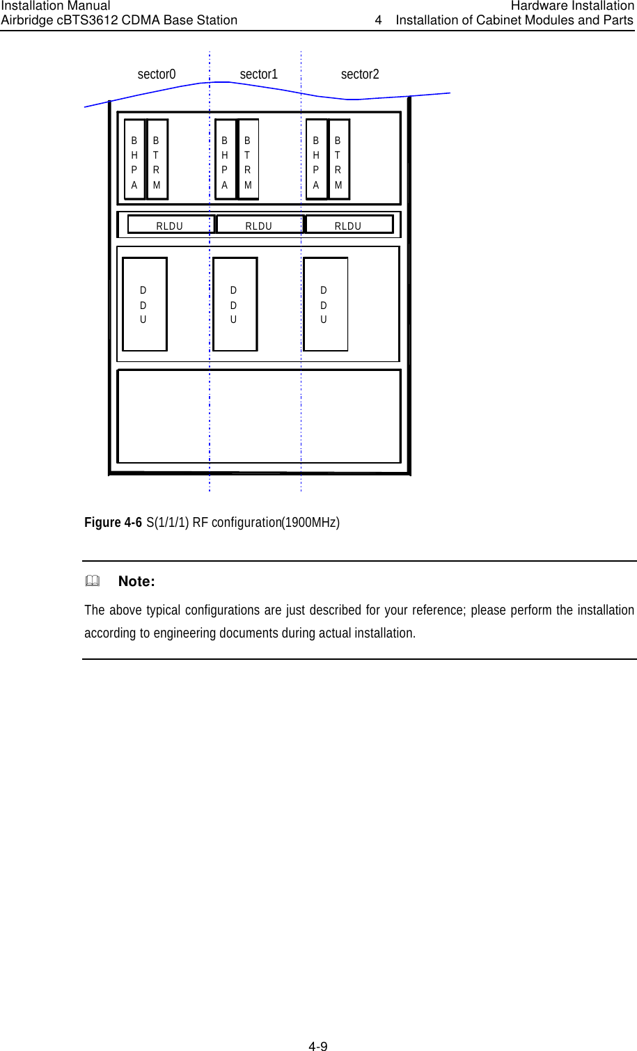
Huawei Technologies CBTS3612-1900 CDMA Base Station User Manual Installation Manual Part 1
Huawei Technologies Co.,Ltd CDMA Base Station Installation Manual Part 1
Contents
- 1. User Manual
- 2. Maintenance Manual
- 3. Installation Manual Part 1
- 4. Installation Manual Part 2
- 5. Installation Manual Part 3
Installation Manual Part 1

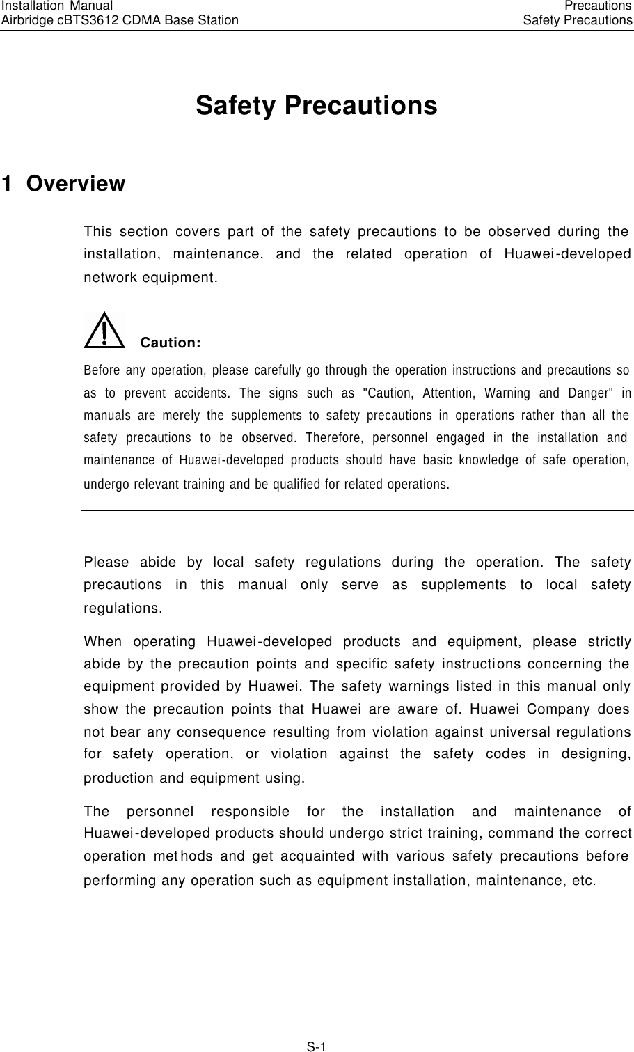
![I. General conventions Convention Description Arial Normal paragraphs are in Arial. Arial Narrow Warnings, cautions, notes and tips are in Arial Narrow. Terminal Display Terminal Display is in Courier New; message input by the user via the terminal is in boldface. II. Command conventions Convention Description boldface font Command keywords (which must be input unchanged) are in boldface. italic font Command arguments for which you supply values are in italics. [ ] Elements in square brackets [ ] are optional. { x | y | ... } Alternative keywords are grouped in braces and separated by vertical bars. One is selected. [ x | y | ... ] Optional alternative keywords are grouped in square brackets and separated by vertical bars. One (or none) is selected. { x | y | ... } * Alternative keywords are grouped in braces and separated by vertical bars. A minimum of one and maximum of all can be selected. [ x | y | ... ] * Optional alternative keywords are grouped in square brackets and separated by vertical bars. Many (or none) are selected. ! A line starting with an exclamation mark is comments. III. GUI conventions Convention Description < > Message entered via the terminal is within angle brackets. [ ] MMIs, menu items, data table and field names are inside square brackets [ ]. / Multi-level menus are separated by forward slashes (/). Menu items are in boldface. For example, [File/Create/Folder]. IV. Keyboard operation Format Description <Key> Press the key with key name expressed with a pointed bracket, e.g. <Enter>, <Tab>, <Backspace>, or<A>. <Key1+Key2> Press the keys concurrently; e.g. <Ctrl+Alt+A>means the three keys should be pressed concurrently.](https://usermanual.wiki/Huawei-Technologies/CBTS3612-1900.Installation-Manual-Part-1/User-Guide-358831-Page-11.png)
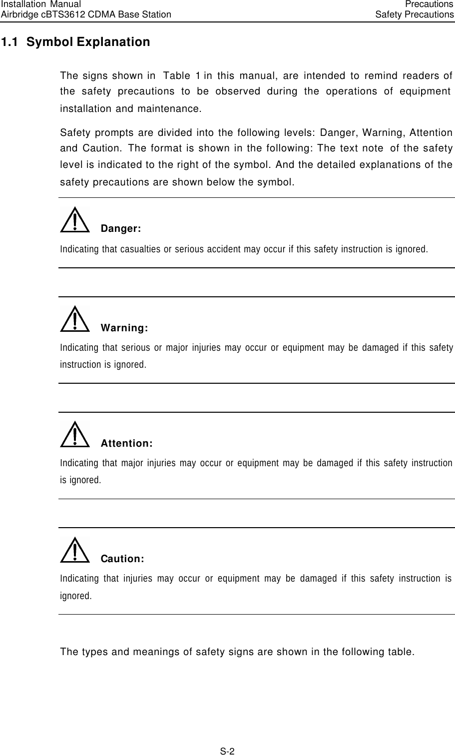
![Format Description <Key1, Key2> Press the keys in turn, e.g. <Alt, A>means the two keys should be pressed in turn. [Menu Option] The item with a square bracket indicates the menu option, e.g. [System] option on the main menu. The item with a pointed bracket indicates the functional button option, e.g. <OK> button on some interface. [Menu1/Menu2/Menu3] Multi-level menu options, e.g. [System/Option/Color setup] on the main menu indicates [Color Setup] on the menu option of [Option], which is on the menu option of [System]. V. Mouse operation Action Description Click Press the left button or right button quickly (left button by default). Double Click Press the left button twice continuously and quickly. Drag Press and hold the left button and drag it to a certain position. VI. Symbols Eye-catching symbols are also used in this document to highlight the points worthy of special attention during the operation. They are defined as follows: Caution, Warning, Danger: Means reader be extremely careful during the operation. & Note Comment, Tip, Knowhow, Thought: Means a complementary description.](https://usermanual.wiki/Huawei-Technologies/CBTS3612-1900.Installation-Manual-Part-1/User-Guide-358831-Page-12.png)