Huawei Technologies CBTS3612-1900 CDMA Base Station User Manual 00 Table of Contents
Huawei Technologies Co.,Ltd CDMA Base Station 00 Table of Contents
Contents
- 1. User Manual
- 2. Maintenance Manual
- 3. Installation Manual Part 1
- 4. Installation Manual Part 2
- 5. Installation Manual Part 3
Installation Manual Part 3
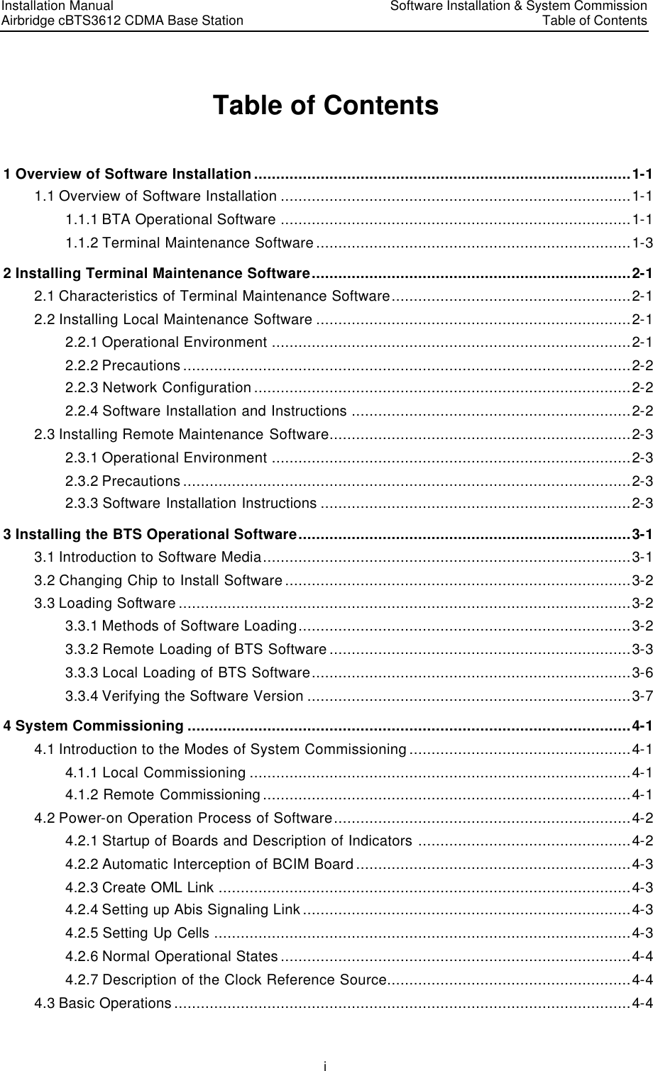
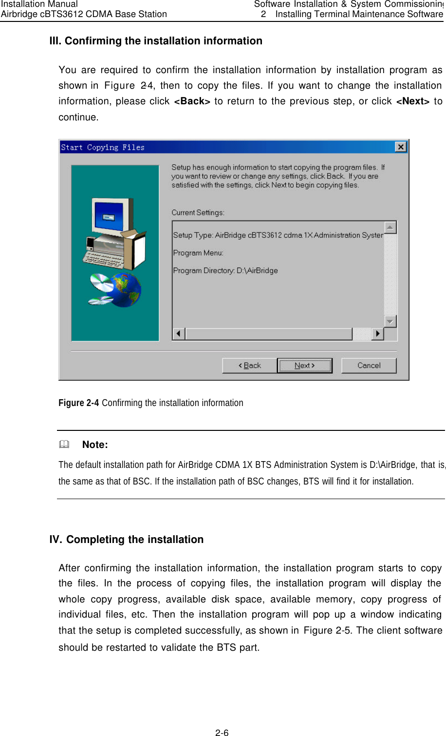
![Installation Manual Airbridge cBTS3612 CDMA Base Station Software Installation & System Commissioning 2 Installing Terminal Maintenance Software 2-2 l 1× integrated network card II. Software configuration Windows 95 or Windows 98. 2.2.2 Precautions For the local maintenance console, following requirements should be observed: 1) Hardware environment is well and stable. 2) Windows9x OS can operate normally. 3) Windows9x installation files and network card driver (provided by the original manufacturer) are furnished. 2.2.3 Network Configuration Configuration of local maintenance network includes the installation and configuration of network cards, installation and configuration of TCP/IP. The configuration is realized through “Add new hardware” and “network” in turn on the control panel of the computer. IP address of the maintenance console should be within the same network segment as that of network interface of BCKM board of BTS. Additionally, the address should be unused by other equipment in the network. The sequence of connection of network cables(Crossover Cable) at the network interface is shown in Table 2-1. Table 2-1 Network interface connection BTS side connector 1 2 3 4 5 6 7 8 PC side connector 3 6 1 4 5 2 7 8 2.2.4 Software Installation and Instructions Local maintenance software (Ftp.exe and Telnet.exe) is self-contained by Windows9x. It is unnecessary to install it additionally. To run Ftp and Telnet: click the [Start/Running] in the system menu of the computer, and input “ftp xxx.xxx.xxx.xxx” and ”telnet xxx.xxx.xxx.xxx” into the dialogue box of “run”. “xxx.xxx.xxx.xxx” is the IP address of BCKM network interface. Then log on the BCKM board.](https://usermanual.wiki/Huawei-Technologies/CBTS3612-1900.Installation-Manual-Part-3/User-Guide-358833-Page-7.png)
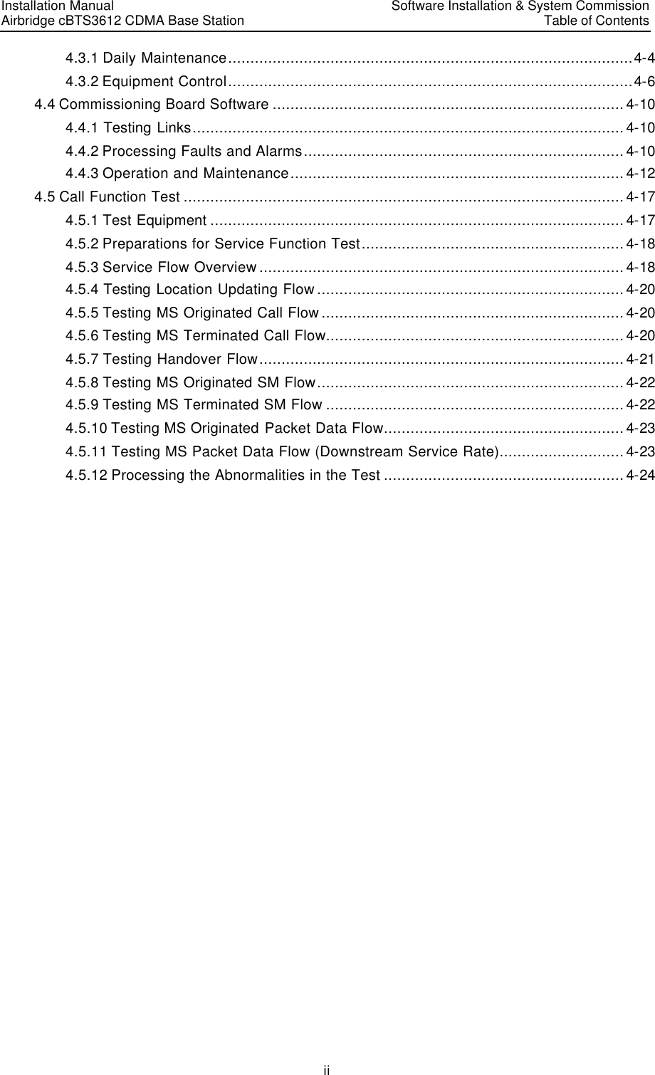
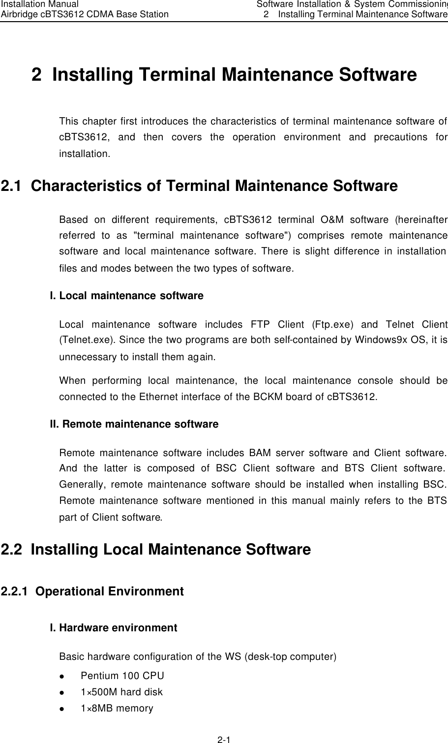
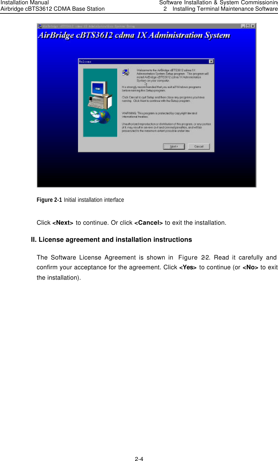
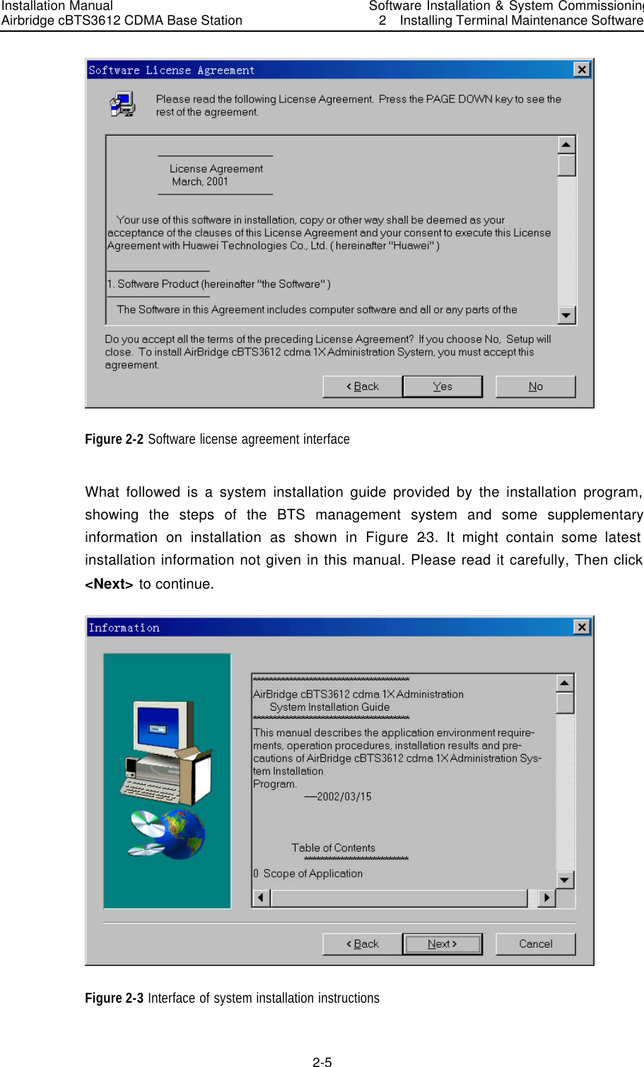
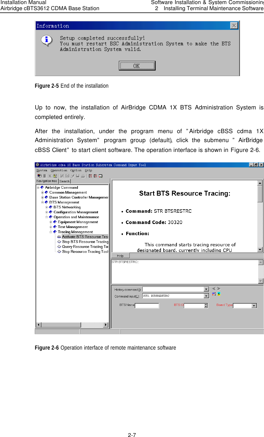
![Installation Manual Airbridge cBTS3612 CDMA Base Station Software Installation & System Commissioning 2 Installing Terminal Maintenance Software 2-3 2.3 Installing Remote Maintenance Software 2.3.1 Operational Environment Operational environment of remote maintenance software (referring to BTS part of Client software only) is based on the platform that has been installed with Client software BSC part. Hardware environment and software configuration are not required additionally. 2.3.2 Precautions 1) Make sure that no any software program not necessary for the operating system has been installed on the computer; Otherwise, it may lead to operational conflicts that may cause the MML client software to run unstably or not run at all. Moreover, make sure that a stable and good network hardware environment has been established. 2) Obtain a complete set of installation files and readme files provided by Huawei, as well as a legal product serial number. 3) BTS part of Client software should be installed on the basis that the corresponding BSC part has been already installed. Note the corresponding relationship between versions of the two before installation. 2.3.3 Software Installation Instructions After installing the BSC part of client software, corresponding BTS part should be installed. For installation of client software BSC part, please refer to the relevant content of “Software Installation” module in “AirBridge cBSC6600 CDMA Base Station Controller Installation Manual”. Following specifically introduces the installation of client software BTS part: I. Starting SETUP.EXE Insert the installation disk into the disk drive. If auto execution has been set for the system, the program will begin starting. Otherwise, select the submenu [Run (R)] from [Start] menu of the Windows and key in “<SETUP>“ (key in the corresponding driver symbol and path if it is not the current path), then press <Enter>. The installation program will start. Or use the Resource Manager to browse and run the file “SETUP.EXE”. You can also copy the files in the installation disk to the same directory and run them. Then there appears a [Welcome] window as shown in Figure 2-1.](https://usermanual.wiki/Huawei-Technologies/CBTS3612-1900.Installation-Manual-Part-3/User-Guide-358833-Page-8.png)
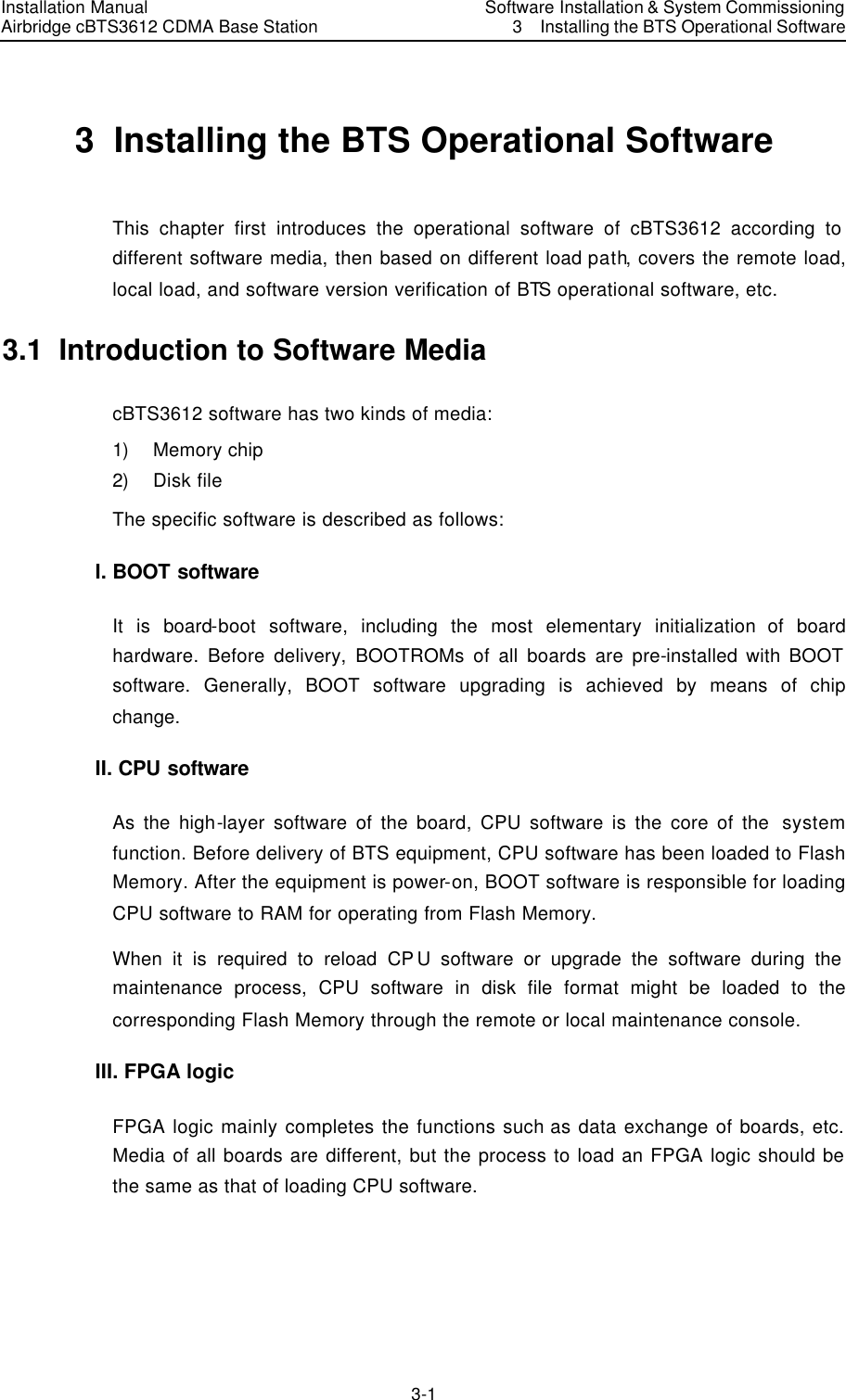
![Installation Manual Airbridge cBTS3612 CDMA Base Station Software Installation & System Commissioning3 Installing the BTS Operational Software 3-5 <Macro BTS Loading Management> of <Macro BTS Management >, click the shortcut of <Create Input Interface> , then input as the following steps: Select the type of the board to be created with loading information in [Board Type]. Select the type of board software in [Software Type]. Input the version No. of the software to be downloaded into [Software Version No.] (Version No. of the software must meet the specification). Input the path of the software to be loaded (i.e. the directory for loading in the previous step) into [Path of File Loaded]. Input the name (the corresponding file name under the software loading directory in the previous step) of the corresponding file to be loaded into [Name of File Loaded]. Click the shortcut of <Execute Command> to create the information for software loading of the corresponding board. 3) Operations for software downloading Execute <Download BTS Software or Data Operation (DLD BTSSW)> on the <Macro BTS Loading Management> of <Macro BTS Management >, click the shortcut of <Create Input Interface> , and then input as the following steps: Input the name of the BTS to download the software into [BTS Name] (this step may be ignored). Input the ID of the BTS to download the software, into [BTS ID]. Select the activation mode of the software to be downloaded from [Software Activation Mode]. Select the object type of the software to be downloaded from [Object Type]. Select the software type of the corresponding object from [Software Type]. The information that is input into [Software Version] must be in accordance with the version No. of the software that has created the corresponding loading information. Select the number of the BTS board to be downloaded from [Board ID]. Click the shortcut of <Execute Command> to download the software of the corresponding board. If this operation is successful, BTS is to download the corresponding software to BTS BCKM board and save it. Then the software on BCKM will be downloaded to the specified board and the loading progress will be shown with a step length of 5%. When the step length for loading progress reaches 100%, it indicates the software has been downloaded to the specified boards of the BTS from the BCKM board. Then, the board will verify the validity of the software](https://usermanual.wiki/Huawei-Technologies/CBTS3612-1900.Installation-Manual-Part-3/User-Guide-358833-Page-17.png)
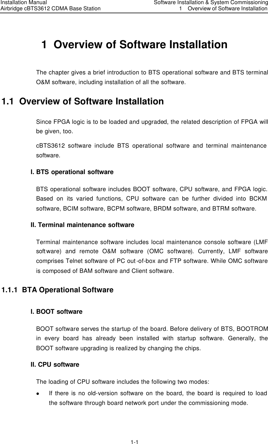
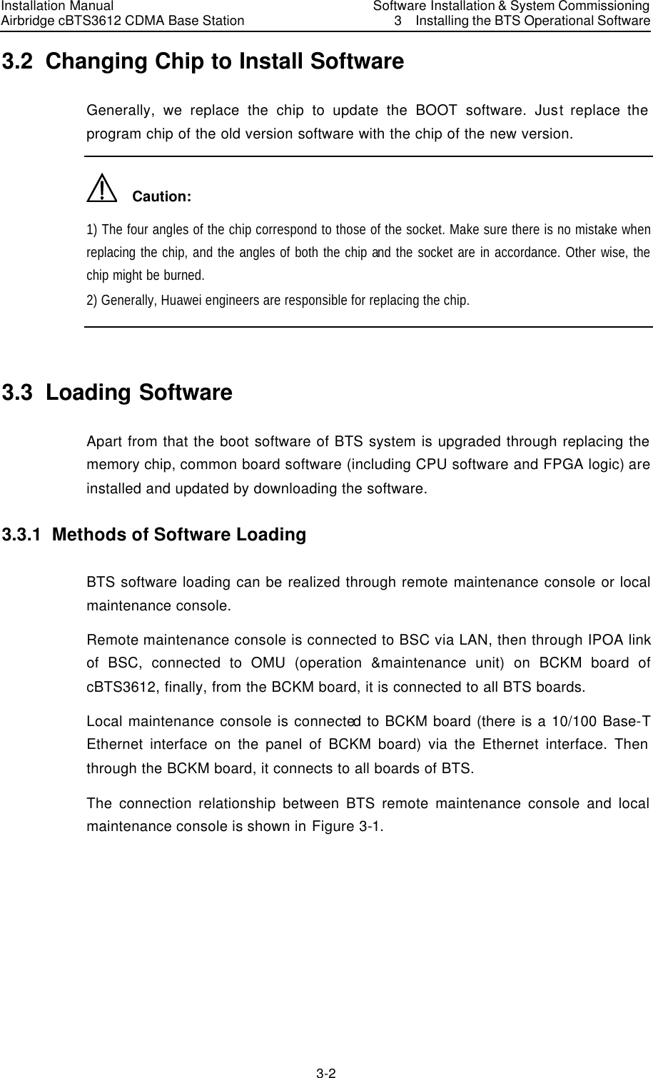
![Installation Manual Airbridge cBTS3612 CDMA Base Station Software Installation & System Commissioning3 Installing the BTS Operational Software 3-6 downloaded and perform the format conversion of the software, write it into Flash Memory, and activate it by resetting. Finally, a period of time later, related indication will show that the downloading is successful. 4) Operations for software uploading Execute <Load BTS Data Operation (ULD BTSSW)> on the <Macro BTS Loading Management> of <Macro BTS Management >, click the shortcut of <Create Input Interface> , and then input as the following steps: Input the name of BTS to upload the software into [BTS Name] (this step may be ignored); Input the ID of the BTS to upload the software into [BTS ID]. Select the object type of the software to be uploaded from [Object Type]; Click the shortcut of <Execute Command> to upload the corresponding BTS configuration data. If this operation is successful, BTS is to run FTP to upload the data information of the specified version to the remote BAM, and save it under the file loading path designated when creating the information of software loading. 3.3.3 Local Loading of BTS Software I. Overview If there is the program in old version on the board, and it can still run normally, software/FPGA logic can be loaded and upgraded in this way. The connection for local loading is shown in Figure 3-2. PCNetwork cableBCIMBCKMBRDMBCPMBTRM Figure 3-2 Local loading connection](https://usermanual.wiki/Huawei-Technologies/CBTS3612-1900.Installation-Manual-Part-3/User-Guide-358833-Page-18.png)
![Installation Manual Airbridge cBTS3612 CDMA Base Station Software Installation & System Commissioning3 Installing the BTS Operational Software 3-7 II. Specific steps to download the software saved in the local maintenance console 1) When the BTS is power-on, and runs normally, login to OMU of the BCKM board through the local FTP of PC. Before the operation, get the IP address of network interface of BCKM board, then key in the following in the DOS environment: “ftp xxx.xxx.xxx.xxx”. Here the “xxx.xxx.xxx.xxx” is the IP address of the network interface of BCKM board. Then input the user name and the password to complete the login according to the prompt. 2) Input the command of <Put File Name>, and the path of the file should be designated in the file name. 3) Input the command of <Literal Act Board Software ID>, and activate the downloaded software/logic of the corresponding board. For example: ”literal act brdm.fpg 0”. What is activated in this example is the FPGA software of BRDM 0. 4) Input <Literal Result> to view whether the activation of the software is successful. 3.3.4 Verifying the Software Version Originate a query through the remote maintenance console or the local maintenance console to get the version information of the running software of BTS boards. I. Get the version information of board software via the remote maintenance console Start the remote maintenance console software (Airbridge cBSC6600 cdma 1X Administration System Client), and Select <BTS Management> in the command tree. Then execute <Query BTS Board Version Information (DSP BTSBRDVER)> on the <Macro BTS Equipment Management> of <Macro BTS Management>, click the shortcut of <Create Input Interface>, and finally input as the following steps: Input the name of the BTS to be queried into [BTS Name] (this step may be ignored). Select the ID of the BTS to be queried from [BTS ID]. Select the BTS board to be queried from [Board Type]. Select the number of the BTS board to be queried from [Board ID]. Click the shortcut of <Execute Command> to get the result of the query in BTS board version information in the maintenance window;](https://usermanual.wiki/Huawei-Technologies/CBTS3612-1900.Installation-Manual-Part-3/User-Guide-358833-Page-19.png)
![Installation Manual Airbridge cBTS3612 CDMA Base Station Software Installation & System Commissioning 4 System Commissioning 4-5 Since the command line-based operations of BTS local maintenance system are basically the same as the operations of BTS terminal maintenance system of OMC, this chapter will specially introduce the relevant maintenance operations of BTS by taking the more visualized OMC terminal maintenance system as an example. I. Query the operation status of BTS board Start the remote maintenance console software (Airbridge cBSC6600 cdma 1X Administration System Client), choose <BTS Management> in the command tree. Enter <Query BTS Information Board Status (DSP BTSBRDSTAT)> on the <Macro BTS Equipment Management> of <Macro BTS Management>, click the shortcut of <Create Input Interface>, and then input the following: Input the name of the BTS into [BTS Name] (this step may be ignored); Select the ID of the BTS to be queried from [BTS ID]; Select BTS board to be queried from [Board Type]; Select the number of the BTS board to be queried from [Board ID]. Click the shortcut of <Execute Command> to get the result of the query about the corresponding BTS board status in the maintenance window. II. View the version information of BTS board Start the remote maintenance console software (Airbridge cBSC6600 cdma 1X Administration System Client), and Select <BTS Management> in the command tree. Then enter <Query BTS Board Version Information (DSP BTSBRDVER)> on the <Macro BTS Equipment Management> of <Macro BTS Management>, click the shortcut of <Create Input Interface>, and finally input the following: Input the name of the BTS to be queried into [BTS Name] (this step may be ignored). Select the ID of the BTS to be queried from [BTS ID]. Select the BTS board to be queried from [Board Type]. Select the number of the BTS board to be queried from [Board ID]. Click the shortcut of <Execute Command> to get the result of the query in BTS board version information in the maintenance window; III. BTS resource management 1) Start BTS resource tracing Start the remote maintenance console software (Airbridge cBSC6600 cdma 1X Administration System Client), select <BTS Management> in the command tree.](https://usermanual.wiki/Huawei-Technologies/CBTS3612-1900.Installation-Manual-Part-3/User-Guide-358833-Page-25.png)
![Installation Manual Airbridge cBTS3612 CDMA Base Station Software Installation & System Commissioning 4 System Commissioning 4-6 Enter <Start BTS Resource Tracing (STR BTSRESTRC)> on the <Macro BTS Tracing Management> of <Macro BTS Management>, click the shortcut of <Create Input Interface> , and then input the following: Input the name of the BTS into [BTS Name] (this step may be ignored). Select the ID of the BTS to be managed from [BTS ID]. Select the type of the board to be traced from [Board Type]. Select the number of the board to be traced from [XX Board ID]. “XX” indicates the type of the board to be traced. Select the name of the resource to be traced from [Name of Traced Resource]. Click the shortcut of <Execute Command> to get the result of the tracing information for the corresponding BTS board resource. 2) Stop BTS resource tracing Start the remote maintenance console software (Airbridge cBSC6600 cdma 1X Administration System Client), select <BTS Management> in the command tree. Enter <Stop BTS Resource Tracing (STP BTSRESTRC)> on the <Macro BTS Tracing Management> of <Macro BTS Management>, click the shortcut of <Create Input Interface> , and then input the following: Input the name of the BTS into [BTS Name] (this step may be ignored). Select the ID of the BTS to be managed from [BTS ID]. Select the type of the board no longer to be traced from [Board Type]. Select the number of the board no longer to be traced from [XX Board ID]. ”XX” indicates the type of the board to be traced. Select the name of the resource no longer to be traced from [Name of Traced Resource]. Click the shortcut of <Execute Command> to stop reporting the result of tracing information of the corresponding BTS board resource. 4.3.2 Equipment Control The corresponding operations may be performed to the board by viewing the operation conditions of the board, including: resetting, self-test, loopback test, etc. I. Resetting BTS board Board resetting can be achieved through the remote BTS O&M system and BTS local maintenance system. OMU issues the board resetting command to the](https://usermanual.wiki/Huawei-Technologies/CBTS3612-1900.Installation-Manual-Part-3/User-Guide-358833-Page-26.png)
![Installation Manual Airbridge cBTS3612 CDMA Base Station Software Installation & System Commissioning 4 System Commissioning 4-7 corresponding board. In receipt of the command, the board executes the resetting operation, and reports the resetting report messages, then waits for the initial data issued from OMU. Since board resetting may affect the operation of the system, it is recommended that the user should use it prudently. The method for resetting on the remote BTS O&M system is as follows: Start the remote maintenance console software (Airbridge cBSC6600 cdma 1X Administration System Client), select <BTS Management> in the command tree. Enter <Reset BTS Board (RST BTSBRD)> on the <Macro BTS Equipment Management> of <Macro BTS Management>, click the shortcut of <Create Input Interface> , and then input the following: Input the name of the BTS into [BTS Name] (this step may be ignored). Select the ID of the BTS to be managed from [BTS ID]. Select the type of the BTS board to be reset from [Board Type]. Select the number of the BTS board to be reset from [XX Board ID]. ”XX” indicates the type of the board to be reset. Click the shortcut of <Execute Command> to execute the operation of the corresponding BTS board resetting. II. BTS self-test In receipt of the self-test command issued from OMU, BTS board executes the self-test operation, and reports the result of the self-test. BTS self-test can be started or stopped via the remote BTS O&M terminal. 1) Start BTS self-test Start the remote maintenance console software (Airbridge cBSC6600 cdma 1X Administration System Client), select <BTS Management> in the command tree. Enter <Activate BTS Self-test (STR BTSSELFTST)> on the <Macro BTS Test Management> of <Macro BTS Management>, click the shortcut of <Create Input Interface> , and then input the following: Input the name of the BTS into [BTS Name] (this step may be ignored); Select the ID of the BTS to be managed from [BTS ID]. Select the type of the BTS board to be tested from [Board Type]. Select the number of the BTS board to be tested from [XX Board ID]. ”XX” indicates the type of the board to be tested. Click the shortcut of <Execute Command> to start the self-testing of the corresponding BTS board.](https://usermanual.wiki/Huawei-Technologies/CBTS3612-1900.Installation-Manual-Part-3/User-Guide-358833-Page-27.png)
![Installation Manual Airbridge cBTS3612 CDMA Base Station Software Installation & System Commissioning 4 System Commissioning 4-8 III. BTS loopback test BTS loop test is used to test the boards of BTS. The length of the test message is variable, which helps to detect whether the link is block-free effectively. Loopback test can be performed on the remote BTS O&M system. The method for operation is as follows: 1) Start loopback test of boards Start the remote maintenance console software (Airbridge cBSC6600 cdma 1X Administration System Client), select <BTS Management> in the command tree. Enter <Activate BTS Loopback Test (STR BTSLPBACKTST)> on the <Macro BTS Test Management> of <Macro BTS Management>, click the shortcut of <Create Input Interface> , and then input the following: Input the name of the BTS into [BTS Name] (this step may be ignored); Select the ID of the BTS to be managed from [BTS ID]. Select the type of the BTS board to be tested from [Board Type]. Select the number of the BTS board to be tested from [XX Board ID]. ”XX” indicates the type of the board to be tested. Input the information of board loopback test into [Board Loopback Te st Information]. Click the shortcut of <Execute Command> to start the loopback testing of the corresponding BTS board. IV. BTS E1 test BTS E1 may facilitate the testing of the physical transmission link between BSC and BTS via the remote O&M terminal, moreover to facilitate locating the transmission problems or evaluating the quality of the transmission link. 1) Start BTS E1 test Start the remote maintenance console software (Airbridge cBSC6600 cdma 1X Administration System Client), select <BTS Management> in the command tree. Enter <Start BTS E1 Test (STR BTSE1TST)> on the <Macro BTS Test Management> of <Macro BTS Management>, click the shortcut of <Create Input Interface> , and then input the following: Input the name of the BTS into [BTS Name] (this step may be ignored); Select the ID of the BTS to be managed from [BTS ID]. Select the number of the BCIM board to be tested from [BCIM Board ID].](https://usermanual.wiki/Huawei-Technologies/CBTS3612-1900.Installation-Manual-Part-3/User-Guide-358833-Page-28.png)
![Installation Manual Airbridge cBTS3612 CDMA Base Station Software Installation & System Commissioning 4 System Commissioning 4-9 Select the type of the loopback to be tested from [Loopback Test Type]. Select the E1 link to be tested from [E1 Link No.]. Select the length of the test time for loopback from [Test Time (Min)] This parameter is not mandatory. If the E1 link includes the O&M link of BTS, it is required to select the length of the test time for loopback. Otherwise, the O&M link of BTS is not to be recovered normally. Click the shortcut of <Execute Command> to start the loopback testing of the corresponding BTS E1 link. 2) Stop BTS E1 test Start the remote maintenance console software (Airbridge cBSC6600 cdma 1X Administration System Client), select <BTS Management> in the command tree. Enter <Stop BTSE1 Test (STP BTSE1TST)> on the <Macro BTS Test Management> of <Macro BTS Management>, and click the shortcut of <Create Input Interface> , then input the following: Input the name of the BTS into [BTS Name] (this step may be ignored). Select the ID of the BTS to be managed from [BTS ID]. Select the number of the BCIM board no longer to be tested from [BCIM Board ID]. Select the type of the loopback no longer to be tested from [Loopback Test Type]. Select the E1 link to be tested from [E1 Link No.]. Click the shortcut of <Execute Command> to stop the loopback test of the corresponding BTS E1 link. Caution: If the value of [Test Time] is selected before starting BTS E1 test, this E1 test will automatically stop after it has been running for the scheduled time. Regarding the tested E1 link containing the BTS O&M link, the relevant E1 loopback test will be terminated depending on the time parameter input into the [Test Time].](https://usermanual.wiki/Huawei-Technologies/CBTS3612-1900.Installation-Manual-Part-3/User-Guide-358833-Page-29.png)