Huawei Technologies CBTS3612-1900 CDMA Base Station User Manual Installation Manual Part 2
Huawei Technologies Co.,Ltd CDMA Base Station Installation Manual Part 2
Contents
- 1. User Manual
- 2. Maintenance Manual
- 3. Installation Manual Part 1
- 4. Installation Manual Part 2
- 5. Installation Manual Part 3
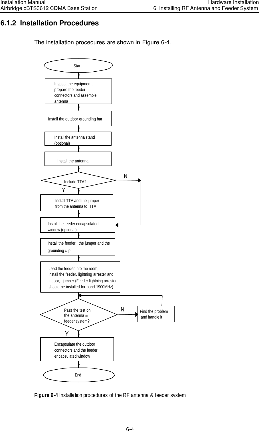
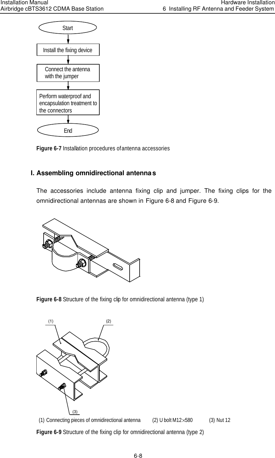
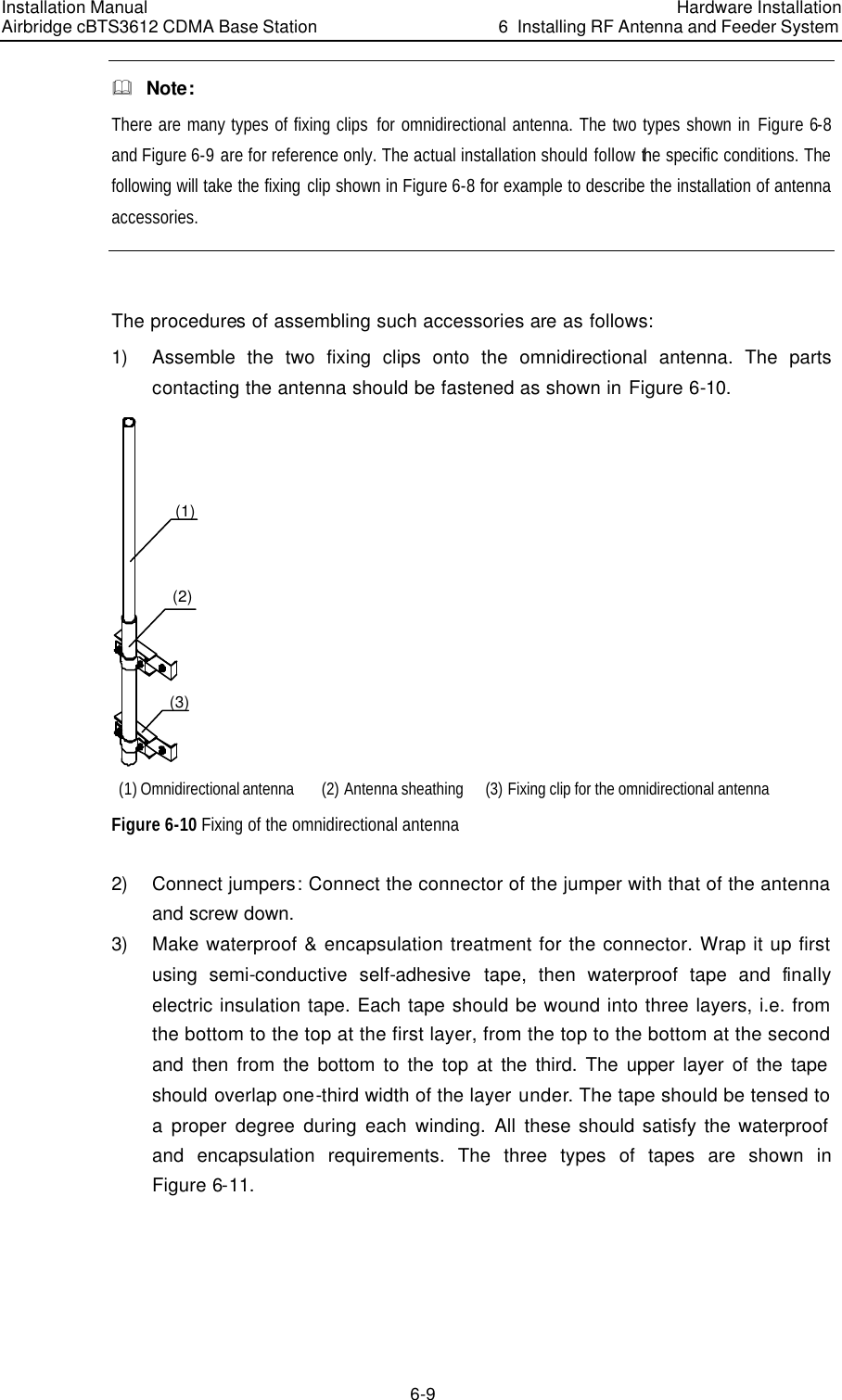
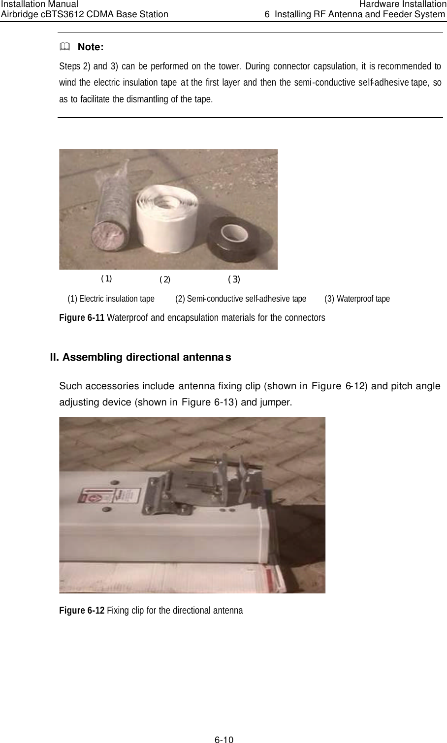
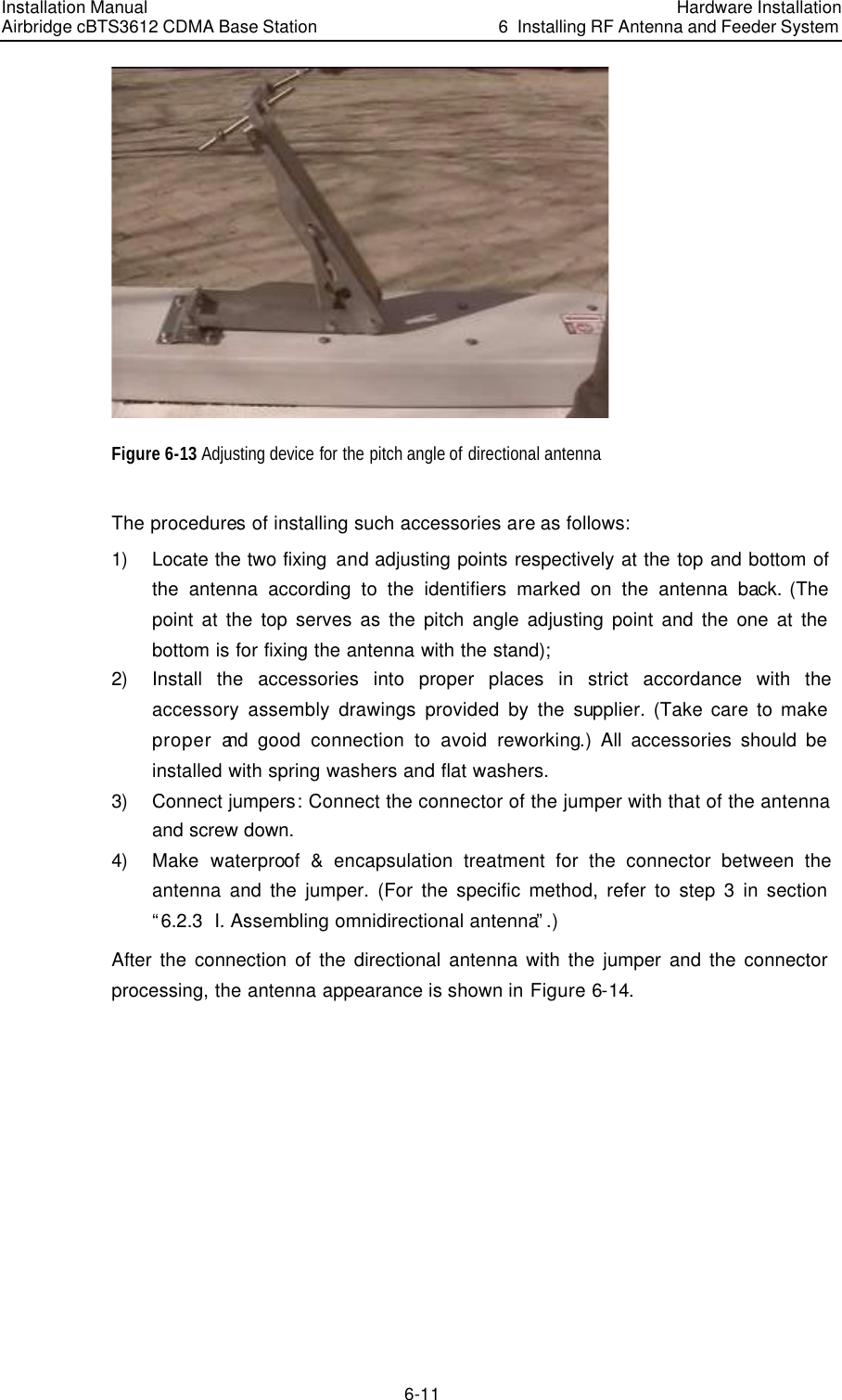
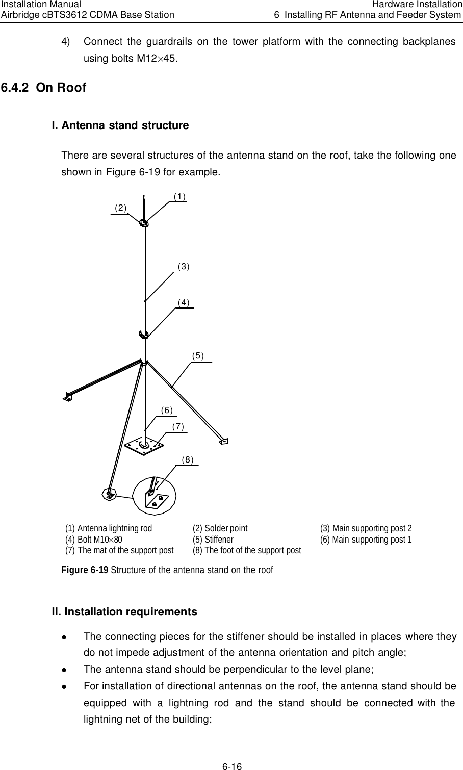
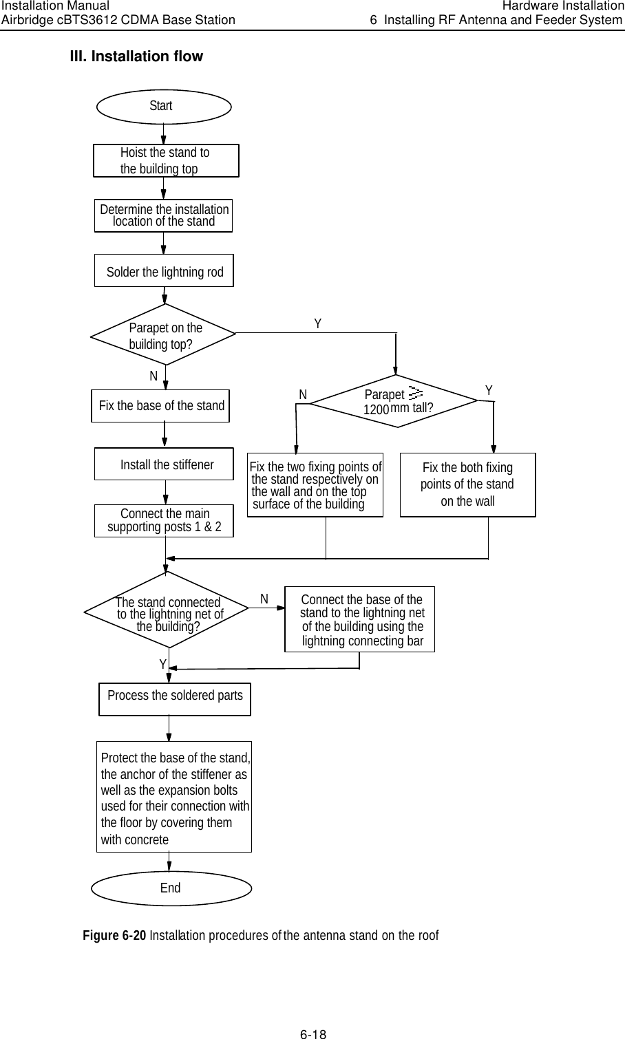
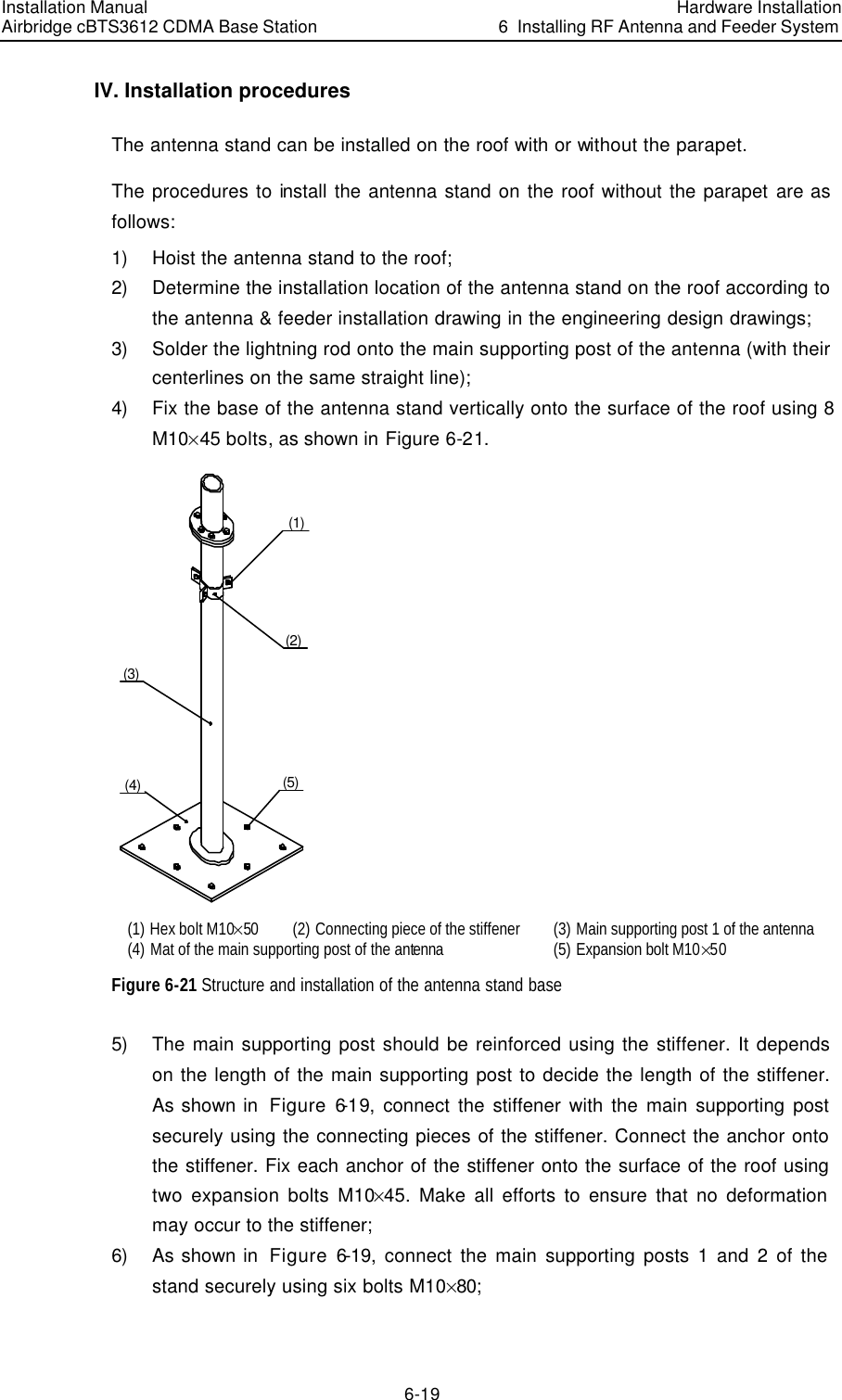
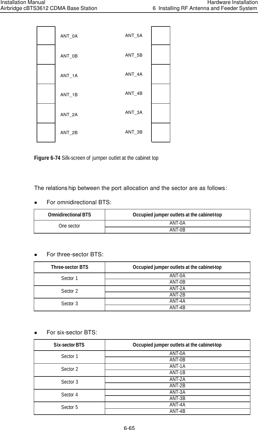
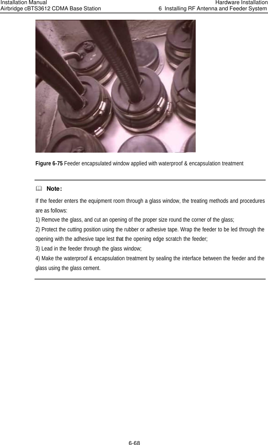
Installation Manual Part 2