Huawei Technologies CBTS3612-1900 CDMA Base Station User Manual Installation Manual Part 2
Huawei Technologies Co.,Ltd CDMA Base Station Installation Manual Part 2
Contents
- 1. User Manual
- 2. Maintenance Manual
- 3. Installation Manual Part 1
- 4. Installation Manual Part 2
- 5. Installation Manual Part 3
Installation Manual Part 2

Installation Manual
Airbridge cBTS3612 CDMA Base Station Hardware Installation
5 Cable Installation
5-1
5 Cable Installation
5.1 Types and Functions of Cables
This chapter aims to introduce the cables (including optical fibers) to be installed at
the work site. The types and functions of these cables are introduced in Section
“5.1.1 Cables to be Installed and Distributed at the Work Site”. The distribution of
cables is introduced in the later part of this chapter. The types, functions, connection
methods and precautions of those cables to be connected at the work site are
introduced in section “5.1.2 Cables to be Connected at Work Site”.
The cables inside the cabinet have been already installed prior to delivery. Relevant
details are available in Appendix G.
5.1.1 Cables to be Installed and Distributed at the Work Site
The cables to be installed and distributed at the work site include: Grounding cables,
power cables, optical fibers, transmission cables and the cables connected to
environment monitoring instrument. All the cables are connected to the top of the
cabinet except that optical fiber cables are connected to the BRDM board of the
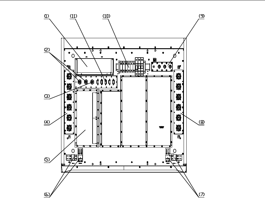
baseband subrack. The top of the cabinet is shown in Figure 5-1.
Installation Manual
Airbridge cBTS3612 CDMA Base Station Hardware Installation
5 Cable Installation
5-2
(1) EMI filter (2) GPS/GLONASS antenna connector (3) Connector for the receiver antenna
test
(4) Antenna connector (5) E1 lightning protection board (6) Exit for outgoing fibers
(7) Exit for outgoing fibers (8) Antenna connector (9) PE grounding copper bar
(10) Power terminal block (11) DB9 connector
Figure 5-1 Layout of the cabinet top
I. Grounding cables
The grounding cables include protection grounding cables for the cabinet and
grounding cables for cabling racks. The latter also includes grounding cables for
indoor cabling rack and outdoor cabling rack.
A well-grounded BTS system is fundamental to the stable and reliable running of the
BTS. It is also primary to the lightning protection and anti-interference functions of
the BTS.
II. Power cables
The -48V DC power is transmitted to the terminal block on the top of cBTS3612
through the power cable, thus, the whole BTS is powered.

Installation Manual
Airbridge cBTS3612 CDMA Base Station Hardware Installation
5 Cable Installation
5-3
III. Optical fibers
Optical fibers include fibers inside the cabinets, fibers for combined cabinets and
fibers for SoftSite cascading. Cables inside cabinets and cables for the combined
cabinets are used to complete the connection between the BRDM of the baseband
subrack and the BTRM module of the RF subrack. Cables for SoftSite cascading are
used to connect the BRDM of the BTS baseband subrack and the MTRM module of
the SoftSite.
Optical fibers for combined cabinets are adopted for the installation of combined
cabinets, while optical cables for SoftSite cascading are used for the cascading of
SoftSite.
IV. Transmissoin cables
The transmission cable is made up of E1 trunk cables (generally a transmission
cable contains 4 E1 trunk cables). It provides trunk connection from the BTS to the
BSC or to other BTSs.
V. Cables connected with environment monitoring instruments
The cables connecting environment monitoring instruments and the cBTS3612
cabinet include a data cable and a shared grounding cable. The environment
monitoring instrument reports the collected environment alarm information to the
BTS through the data cable. It is grounded with the BTS through the shared
grounding cables.
5.1.2 Cables to be Connected at Work Site
I. GPS/GLONASS clock RF cables
cBTS3612 cabinet should be configured with two black soft RF cables. One end of
each cable is connected to the GPS/GLONASS feeder interface on the top of the
cabinet, and the other end is placed in the cable trough. The RF cables should be
connected on the site to the front panel of BCKM in the baseband subrack.
Before connecting the RF cables to the BCKM panel, check which GPS connector
(GPS_0 or GPS_1) at the cabinet-top the GPS jumper has been connected to during
the on-site installation. Choose the corresponding white soft RF cables (already
labeled as GPS_0 or GPS_1), and connect it to the ANT connector on the front panel
of the BCKM according to the silk screen on the connector.

Installation Manual
Airbridge cBTS3612 CDMA Base Station Hardware Installation
5 Cable Installation
5-4
II. Alarm cables from RLDU to the backplane of RF subrack, and power
cables for RLDU module
The alarm cables from the RLDU to the backplane of the RF subrack and the power
cables for the RLDU module have been tied and bound to the RLDU slot in three
groups (each group corresponding to one RLDU module) upon delivery. After
installing the RLDU modules, connect the corresponding alarm cables and power
cables to the CNT and DC-IN connectors on the RLDU modules respectively.
Verify the labels on the alarm cables and power cables to avoid wrong connection.
III. RF cables from CDU/DFU/DDU to cabinet top
For CDU, the upper end of the RF cable from the CDU to the cabinet top has been
installed on the cabinet top already. The lower end is a type N male connector, which
should be connected to the two ports marked as TX/RXM-ANT and RXD-ANT on the
CDU front panel on the site.
Place the extra parts of the cable in the cable trough of the CDU subrack. Each CDU
matches two antennae. The TX/RXM-ANT matches the transmit/receive antenna,
and the RXD-ANT matches the receive diversity antenna. During the installation
note the labels on the cables and make sure the relations are correct. Fasten the
cable connector (first by hand, then with wrench) properly.
The labels of RF cables from the CDU to the cabinet top are consistent with the silk
screens of the antenna feeder interface on the cabinet top. For example, in a group
made up of ANT_0A and ANT_0B, “A” represents main TX/main RX, while “B”
represents diversity RX.
&
Note:
1) When the optional DFU is provided, similar to the CDU, it should also be configured with RF cables
from DFU to the cabinet top. Each DFU should match two antennae, and the TX/RXM-ANT matches
the receive/transmit antennae, while RXD-ANT matches the diversity - receive antenna.
2) When the optional DDU is provided, similar to the CDU, it should also be configured with RF cables
from DDU to the cabinet top. Each DDU should match two antennae, and the TX/RXM-ANT matches
the main receive/transmit antennae, while TX/RXD-ANT matches the diversity - receive/ transmit
antenna.
3) The connection relations between the CDU (or DFU/DDU) and RF cables from the CDU (or
DFU/DDU) to the cabinet top vary according to different BTS configurations. Detailed information is
available in the relevant engineering documents.
Installation Manual
Airbridge cBTS3612 CDMA Base Station Hardware Installation
5 Cable Installation
5-5
5.2 Distributing Grounding Cables
5.2.1 Distributing Protection Grounding Cables for Cabinets
Connect one end of the yellow-green cable strands with cross-sectional area as
25mm2 to the PE grounding bar on the top of the cBTS3612 cabinet, and distribute
the other end orderly along the cabling rack, then connect this end to the
corresponding holes for the protection grounding bar of the equipment room.
5.2.2 Distributing Grounding Cables for Cabling Racks
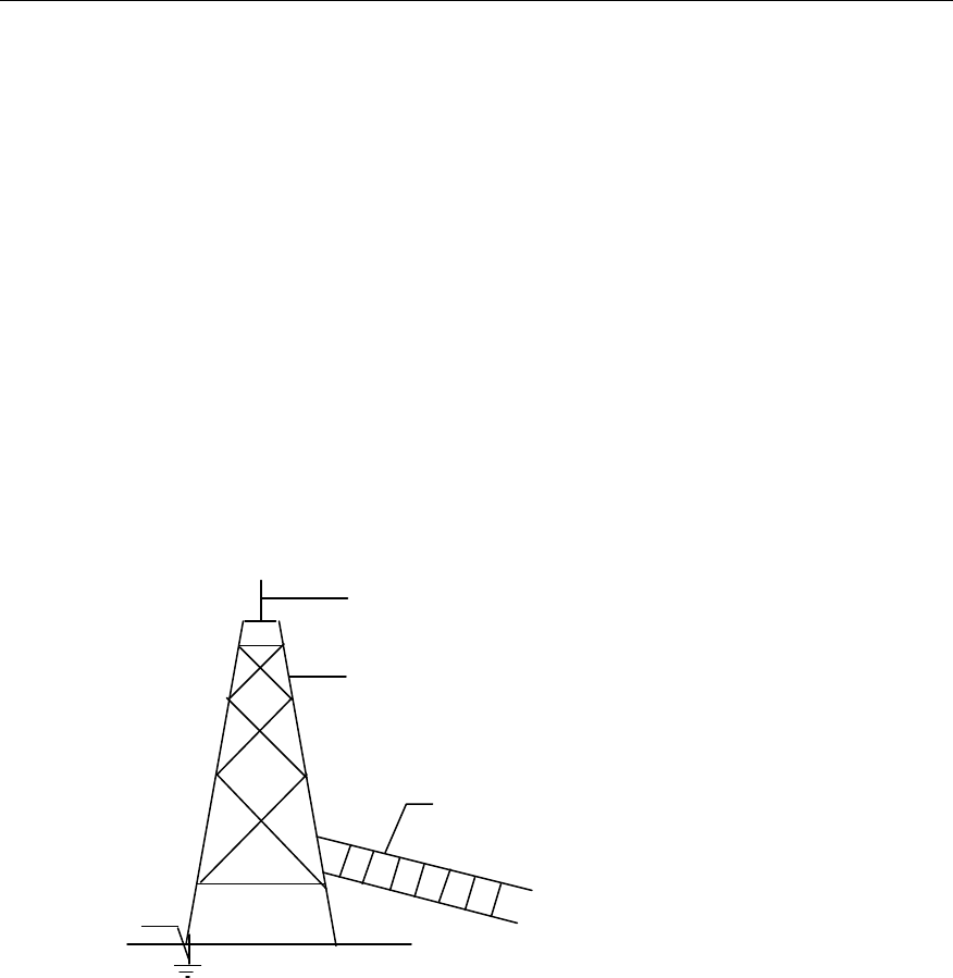
1) Generally, outdoor cabling racks are soldered with the tower directly to ensure a
good connection with the ground. If the outdoor cabling rack does not contact
the tower directly, connect the tower with the outdoor cabling rack by soldering
a flat steel bar to ensure a good connection, as shown in Figure 5-2.
(1)
(2)
(3)
(4)
(1) Lightning arrester (2) Iron tower (3) Outdoor cabling rack (4) Grounding body
Figure 5-2 Grounding of outdoor cabling rack
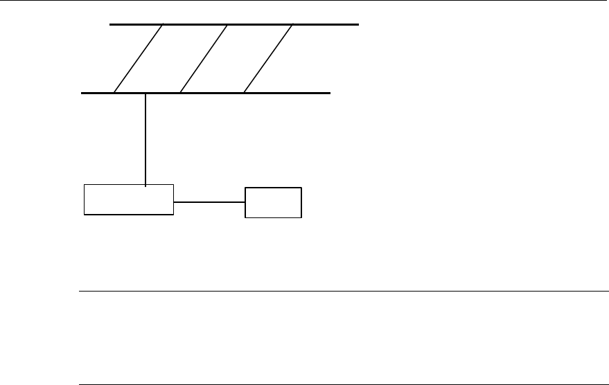
2) The indoor cabling rack can be grounded through the indoor grounding bar. To
start the grounding, first connect the lug at one end of the grounding cable to the
cabling rack and then connect the other lug to the indoor grounding copper bar.
The grounding of the indoor cabling rack is shown in Figure 5-3.
Installation Manual
Airbridge cBTS3612 CDMA Base Station Hardware Installation
5 Cable Installation
5-6
Indoor cabling rack
Grounding bar
Ground
Grounding cables
Figure 5-3 Schematic drawing for indoor cabling rack
&
Note:
The cabling rack and its grounding cables have been installed before the BTS installation. Therefore,
the installation process is not described here.
5.3 Installing and Distributing Power Cables
5.3.1 Preparing Power Cables
I. Tools
Tape, wire nipper, paper knife, hydraulic pliers, insulating tapes, soldering iron and
solder wire.
II. Process
1) Measure the distance between the input port of the -48V terminal block on the
BTS cabinet top and the corresponding wiring terminal of the power supply
cabinet according to the actual cabling path, and then cut cables to the
measured lengths respectively. Adequate redundant cables should be
reserved.
2) Measure the distance between the wiring terminal for protection ground of the
cabinet and the corresponding wire hole for the protection-grounding bar of the
equipment room according to the actual cabling path, then cut cables to the
measured length for protection grounding cables.
3) Cut the insulating cover of each cable head with the paper knife. The length of
the removed cover must equal to that of the cable lug.
Installation Manual
Airbridge cBTS3612 CDMA Base Station Hardware Installation
5 Cable Installation
5-7
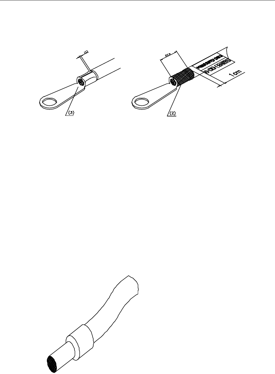
4) During preparation, press the cable lug with the hydraulic pliers, and wrap up
the bare wire and the lug with the insulating tape. Make sure that the bare wire
and the lug are not exposed, as shown in Figure 5-4.
(1) The interval is not more
than 1mm (2) Make sure that all the bare stubs should be
covered with cable caps. (3) Wrap up with tapes
Figure 5-4 Preparing the lugs
5.3.2 Connecting Power Cables
1) Connect the blue cable strands (-48V) to the -48V input terminal of -48V
terminal block on the cabinet, and connect the black cable strands to the GND
input terminal of the -48V terminal block.
2) Adopt the cold-pressed connector to connect the power cables and the -48V
terminal block. The connector is cold-pressed upon delivery. For fixation, just
insert the connector of the power cable into the relevant jack of the terminal
block and fasten screws on the terminal block. The cord end terminal is shown
in Figure 5-5.
Figure 5-5 Cold end terminal
3) Distribute the blue cable strands and black cable strands along the cabling
racks in order, and connect the other end of each cable to the corresponding
Installation Manual
Airbridge cBTS3612 CDMA Base Station Hardware Installation
5 Cable Installation
5-8
wiring terminals of the power supply cabinet. A lug should be prepared for the
connector at the end of a power cable at the work site. First press the lug tight
and solder it. Cover the lug with heat-shrink tubes. The naked wires and the lug
handle should not be exposed. Mark the corresponding serial number on the
Huawei-made label and attach the label on the lug. If the power is switched on,
do not touch other wiring terminals of the cabinet with the adjustable spanner or
screwdriver (wrapping the adjustable spanner up with insulating tapes). the
power label appearance is shown in Figure 5-6.
Figure 5-6 Power label
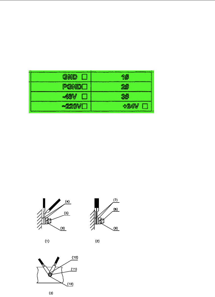
4) During the installation of lugs, if it is necessary to install two or more power
cables on one wiring terminal, the installation should be done as per the
illustration in Figure 5-7. Generally, the lugs should not be overlapped, and the
cross or back-to-back installation method should be used. If overlapping cannot
be avoided, the lug should be bent by 45° or 90° with the bigger lug placed at the
bottom and the smaller one on the top. This is applicable to the lug installation in
any mode.
(1) Bent by 45°or 90° (2) Back-to-back
installation (3) Cross-installation (4) Plain washer
(5) Nut (6) Spring washer (7) Plain washer (8) Nut
(9) Spring washer (10) Plain washer (11) Nut (12) Spring washer
Figure 5-7 Cross-connection of the power cables
Installation Manual
Airbridge cBTS3612 CDMA Base Station Hardware Installation
5 Cable Installation
5-9
5.3.3 Distributing Power Cables
Distribute power cables according to the following principle:
Power cables should be distributed separately from other cables. Inside the rack
they should be bound separately instead of being bound together. Outside the rack
(such as in the cable trough or trench) they should also be bound separately. The
power cables should run through the fixing racks on both sides of the cabinet, and be
bound in the inner part of the lateral of the fixing racks. Each fixing rack should also
be bound. The cable tie knot should be on the outer lateral of the fixing rack.
When distributing the power cables to the terminal block inside the rack, the cabling
path should remain straight and flat. Moreover, the cables should be tied in order.
The power cables, connected to the terminal block far from the upper terminal block,
should be placed at the outer lateral of the rack upon the cabling on a rack. Those
connected to the terminal block near the upper one should be laid on the inner side of
the rack.
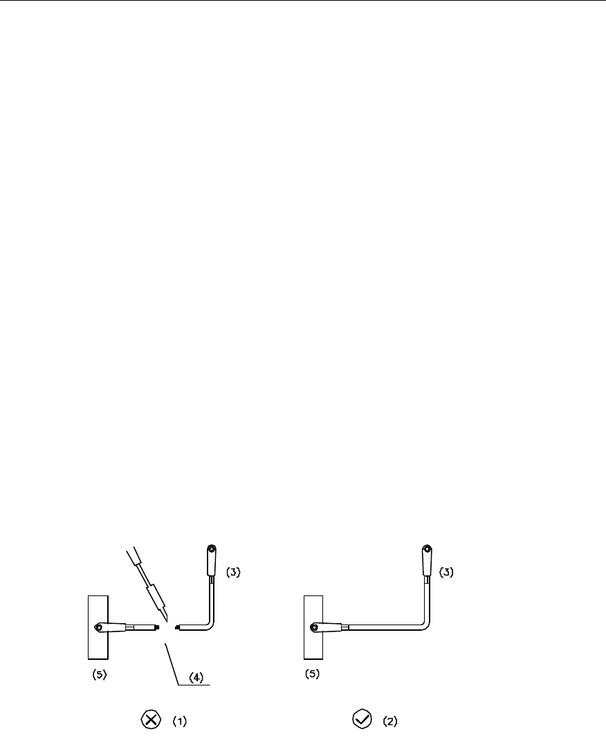
Before distributing power cables, precisely measure the distance between the wiring
busbar and the distribution box and the distance from the distribution box to the
cabinet terminal block. Cables long enough should be reserved for possible cable
shortage in the actual cable distribution. If the reserved cables are not long enough,
stop distributing cable and adopt new ones. It is prohibited to make connections or
welds during the distribution, as shown in Figure 5-8.
(1) Wrong operation--soldering connection
(2) Correct operation – connection without soldering (3) To BTS (4) Weld
(5) Grounding copper bar or copper bar for power supply
Figure 5-8 Wrong operation and correct operation
Installation Manual
Airbridge cBTS3612 CDMA Base Station Hardware Installation
5 Cable Installation
5-10
5.4 Distributing Optical Fibers
5.4.1 Distributing Optical Fibers inside Cabinet
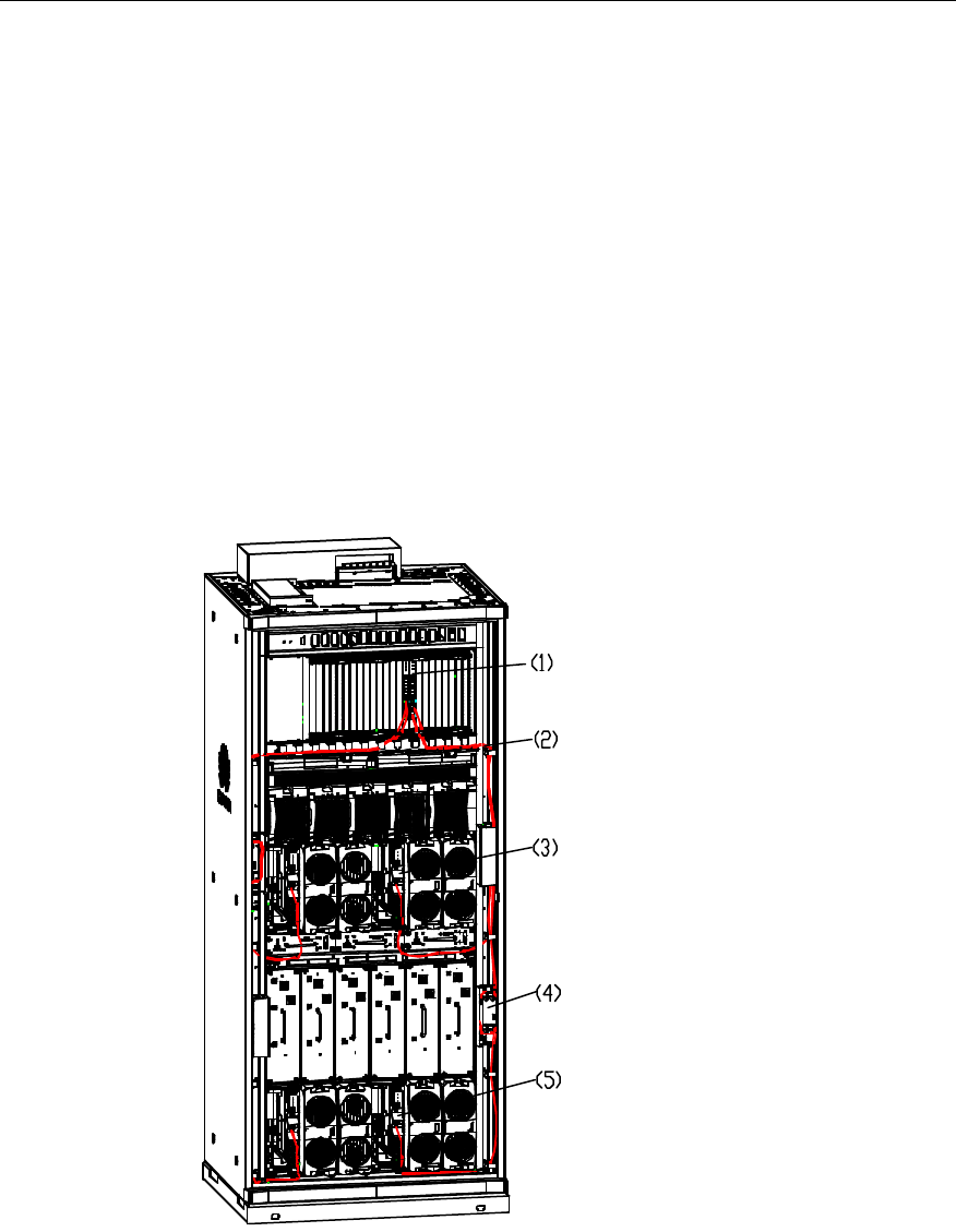
Connection of the optical fibers inside the cabinets refers to connecting the BTRM
module and the BRDM with optical fibers. Each BRDM can export up to 6 optical
fibers from the panel. The fiber length inside the cabinet is 3m.
The optical fibers are led out from the front panel of the BRDM in the baseband
subrack, enter the RF subrack through the cable trough below the baseband subrack
and the cable bushings on both sides of the cabinet. In this way, the optical fibers are
connected to the optical fiber interface of the BTRM. Coil up the redundant optical
fibers and keep them in the cable support. The specific connection is shown in
Figure 5-9.
(1) BRDM board (2) Optical fibers (3) BTRM module
(4) Cable support (5) BTRM module
Figure 5-9 Connecting optical fibers inside the cabinet
Installation Manual
Airbridge cBTS3612 CDMA Base Station Hardware Installation
5 Cable Installation
5-11
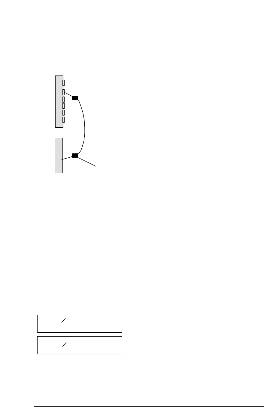
5.4.2 Optical Fiber Labels
Currently all optical fiber labels are blank ones. They should be filled in strictly as per
the relevant specifications, so as to correctly reflect the relationship among BTRM
module, BRDM module, ODF and ODU (for SoftSite). Inside the cabinet, the labels
should be affixed as shown in Figure 5-10.
BRDM
BTRM
(1)
(1) Label of optical fiber from BTRM to BRDM board
Figure 5-10 Optical fiber label positions
The labels are affixed at the place 0.1m to both ends of the fiber in the following
format:
BTRM(T)(ODF) Row No.–Column No.–Row No.(inside ODF)–Port No.–(ODF)–ODU
Name
BRDM(R) Board No.–Port No.
&
Note:
1) For the optical fiber from BTRM to BRDM, only the sector No. (0-5) is allowed in the BTRM label part,
as shown in Figure 5-11.
BTRM(T) 2
ODF
BRDM(R) 0-0
Figure 5-11 Filling format of optical fiber labels
2) For BRDM, the board No. is (0~5) and the port No. is also (0~5);
3) In the label, the "T" and "R" after BTRM and BRDM are slashed.

Installation Manual
Airbridge cBTS3612 CDMA Base Station Hardware Installation
5 Cable Installation
5-12
Installation personnel should strictly follow the above requirements to fill in labels for
convenient future maintenance
5.4.3 Distributing Optical Fibers in Combined Cabinets
The optical fibers between cabinets provide the signal connection from the BRDM of
the basic cabinet to the RF module of the extension cabinet. The extension cabinet
requires 12 sectors of carrier frequency for full configuration. Therefore, each
extension cabinet should be connected with up to 6 pairs of optical fibers.
Procedures for the optical fiber distribution inside the cabinet are available in section
5.4.1 Distributing Optical Fibers inside Cabinet. When distributing and bundling the
optical fibers, pay attention to the following items:
1) Do not bend an optical fiber to a right angle upon distribution. Make it round with
a diameter no less than 8cm if possible. Optical fiber pairs should be bound in
order.
2) Avoid bending the optical fibers as much as possible. The optical fibers between
cabinets can be distributed through the cabling rack, or directly on the
cabinet-top for the consideration of a nice appearance.
3) Keep the redundant optical fibers in the fiber management tray. Do not twist the
fibers; otherwise, it will be very difficult to identify them.
4) Optical fibers should be distributed according to specific conditions and bound
properly. Those fixed onto the beam should be bound at a spacing of 150 mm.
5) Flags at both ends of the optical fiber must be distinct and able to indicate the
correspondence between the RF module and the fiber port on the BRDM of the
baseband subrack.
6) Corrugated plastic tubes must be added to protect the fibers when they are led
out of the cabling rack.
5.4.4 Distributing Optical Fibers for SoftSite Cascading
For the fiber connection procedures for SoftSite cascading, please refer to section
5.4.3 Distributing Optical Fibers in Combined Cabinets.
5.5 Distributing Transmission Cables
5.5.1 Connection and Distribution between E1 Trunk Cables and Cabinets
I. DB25 connector of E1 trunk cables on cabinet top
There are four external DB25 connectors on the E1 lightning protection board on the
cabinet top, each connector with the transmission capacity of 4 E1 cables. Starting
from the front of the cabinet, the four DB25 connectors are numbered E1_0, E1_1,
Installation Manual
Airbridge cBTS3612 CDMA Base Station Hardware Installation
5 Cable Installation
5-13
E1_2, and E1_3 from the front to the back. E1_0 and E1_1 correspond to the BCIM
in Slot 0, and E1_2, E1_3 to the BCIM in Slot 1.
II. Selecting DB25 connector for E1 trunk cable on cabinet top
Generally in the installation, the four DB25 connector, E1_0, E1_1, E1_2, and E1_3
are selected in turn according to the number of configured E1 trunk cable ports. If the
number of ports is not over 4, just select E1_0; if it is over 8 but less than 12, select
E1_0, E1_1, or E1_2.
III. Distributing E1 trunk cables
E1 trunk cables are led out from the DB25 connector on the E1 lightning protection
board on the cabinet top, along the cabling ladder, bundled and fixed at the DDF rack.
The distribution for E1 trunk cables should be carried out in good order.
&
Note:
1) One-port E1 trunk cable is composed of two coaxial cables. Generally, 4 E1 cables form one
transmission cable that connects the E1 lightning protection board on the cabinet top. The numbers of
individual coaxial cables are marked on the DB25 connector. Install these cables by sequence so as to
avoid cross-connection.
2) Several BTSs can form the star, link, and tree networking. E1 trunk cables should be connected for
the BTS networking according to the software configuration. Detailed information is available in the
auxiliary engineering documents.
5.5.2 DDF Installation
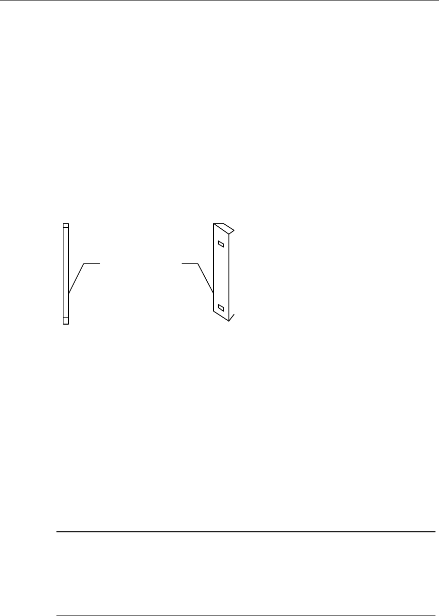
I. DDF (Digital Distribution Frame)
The type of DDF used by cBTS3612 is BTP11Z, as shown in Figure 5-12.
Figure 5-12 The appearance of BTP11Z
Installation Manual
Airbridge cBTS3612 CDMA Base Station Hardware Installation
5 Cable Installation
5-14
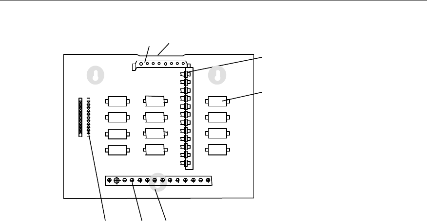
The internal structure of the BTP11Z is shown in Figure 5-13.
(1)
(2)
(3) (4) (5)
(7)(6)
(1) Bianode wall-through SMB socket (2) Lightning arrester with SMB male connectors on both ends
(3) External cable unit with 10 loop cables (4) Grounding bar
(5) Installation hole (6) Bundling trough
(7) The holes for cable outgoing and incoming of DDF
Figure 5-13 Layout of the parts inside BTP11Z
The following accessories are included in the DDF:
l 75W coaxial cables self-loop test cables;
l One cable punchdown tool with 10 loop cables;
l Safe guard unit;
l Expansion bolts (for installation).
Outgoing and incoming cabling modes: Both the incoming and outgoing cables are
connected to the inside of the DDF through the round port at the upper part of DDF.
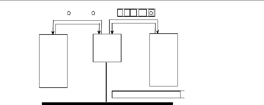
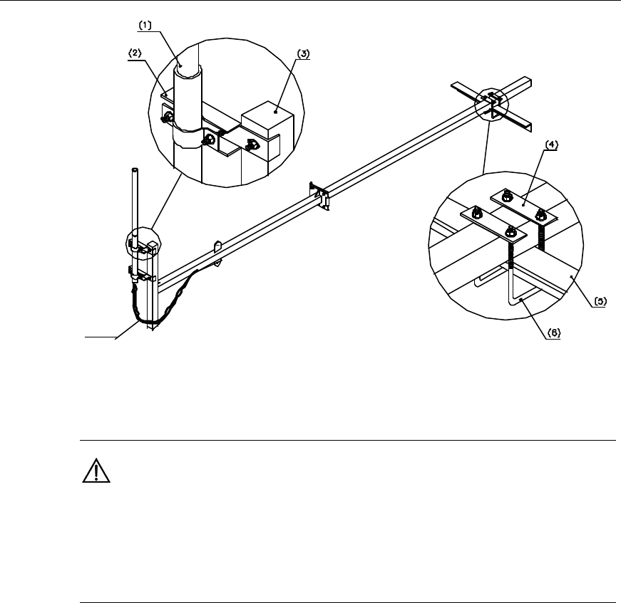
II. Fixing DDF
The installation process for the DDF and trunk cables is shown in Figure 5-14.
Installation Manual
Airbridge cBTS3612 CDMA Base Station Hardware Installation
5 Cable Installation
5-15
DDF
Transmission
equipment BTS
75 or 120
Grounding bar for equipment room
75 ¦¸ or 120
Figure 5-14 Installing DDF
When fixing the DDF, please follow the steps below:
1) Determine the installation location for the DDF according to the engineering
design for the equipment room.
2) Mark the position for the DDF according to its dimensions:
350mm×240mm×116mm
3) Determine the installation holes for the DDF.
4) Drive the expansion bolts into the installation holes.
5) Hang the DDF onto the expansion screws.
6) Tighten the expansion bolts with a screwdriver.
III. Connecting 75
W
trunk cables (coaxial cables) to DDF
Since there is a special E1 lightning protection board on the cabinet top of cBTS3612,
the E1 cables from cBTS3612 to the DDF and from the transmission equipment to
the DDF are both transferred directly. The specific connecting methods are as
follows:
1) The SMB connector should be prepared for the E1 cables connecting
cBTS3612 and the DDF, and the E1 cables connecting the transmission
equipment and the DDF.
2) The E1 cables from cBTS3612 to the DDF and those from the transmission
equipment to the DDF are in one-to-one correspondence. And the
corresponding E1 cables connecting the same transit connector of “bianode
wall-through SMB socket” as shown in Figure 5-13. The 75W trunk cable
connecting the transmission equipment is connected to the right end of the SMB
socket, while the 75W trunk cable connecting cBTS3612 is connected to the left
end as specified.
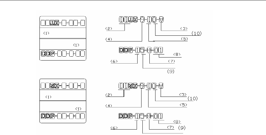
3) The 75W trunk cable should be labeled after connection. The label appearance
and filling format is shown in Figure 5-15. Please strictly follow the format for
convenient future maintenance.
Installation Manual
Airbridge cBTS3612 CDMA Base Station Hardware Installation
5 Cable Installation
5-16
(1) Trunk cable label (2) E1 No. (In each BCIM
board, the number is 0~7)
(3) Row No. (4) Slot No. (0~1)
(5) Subrack No. (6) Row No. (7) Row No. (inside ODF) (8) E1 No. (on DDF)
(9) Column No. (10) Column No.
Figure 5-15 Appearance and filling format for 75W trunk cable labels
IV. Lightning protection and connection between 120
W
trunk cables (twisted
pairs) and DDF
The 120W trunk cables are used for the access of external cable units.
The grounding cable of the 120W trunk cable is connected to the chassis of the DDF,
and the signal cable is fixed at the corresponding position with a cable punchdown
tool. Since every cable unit is all-open unit, the safe guard must be inserted into the
upper part of each unit so that the circuit can be closed. The lightning protection for
the 120W trunk cable is realized in the safe guard. When the current in the trunk
cables raises up to a certain level, the safe guard (self-destruction safe guard) will
disconnect the circuit automatically so as to protect the BTS.
V. DDF grounding
Connect the grounding bar of the equipment room and the grounding bar of the DDF
with the grounding cable of digital distribution box. If the grounding cable is a 75W
trunk cable, it can be connected to the lightning arrester. If the grounding cable is a
120W trunk cable, it can be connected to the grounding bar of the DDF, with the
twisted pairs connected to the external cable unit.

Installation Manual
Airbridge cBTS3612 CDMA Base Station Hardware Installation
5 Cable Installation
5-17
5.6 Distributing Cables Connecting Environment
Monitoring Instrument
I. Connecting data cables
One end of the data cable is a 25PIN connector connected to the monitoring
instrument, while the other end is a 9PIN connector connected to the EAC2 socket
on the cabinet top of BTS.
II. Shared grounding cables
One end of the shared grounding cable is connected with the working ground of the
monitoring instrument, while the other end is connected with the PE grounding
copper bar on the cabinet top of the BTS. In this way, the monitoring instrument is
grounded together with the BTS.
&
Note:
The working principles and installation procedures of the environment monitoring instrument are
available in the manual delivered together with the instrument.
Installation Manual
Airbridge cBTS3612 CDMA Base Station Hardware Installation
6 Installing RF Antenna and Feeder System
6-1
6 Installing RF Antenna and Feeder System
6.1 General
The installation of the RF antenna & feeder system includes antenna installation,
jumper installation, feeder distribution and installation of lightening protection system
for the antenna & feeder. This chapter only describes the installation of
omnidirectional and directional antennas on tower or on roof. The appearances of
the omnidirectional and the directional antenna are shown in Figure 6-1.
(1) (2)
(1) Omnidirectional antenna (2) Directional antenna
Figure 6-1 Antennas
To guarantee the project quality and the safety of constructors, the installation
should be carried out on sunny days without strong wind. During the installation
especially the antenna installation, the installation personnel should attach high
importance to safety and conform to relevant safety regulations.
6.1.1 Structure
The RF antenna & feeder system is composed of antenna, feeder, jumper, feeder
grounding clip and tower-top amplifier (optional).
&
Note:
The tower-top amplifier is abbreviated as “TTA”. It is an optional device operating at band 1900MHz.
When it is adopted, lightning arrester should be installed for the antenna & feeder system. The TTA in
this system is of the triplex type. Both Rx and Tx signals can go through it.
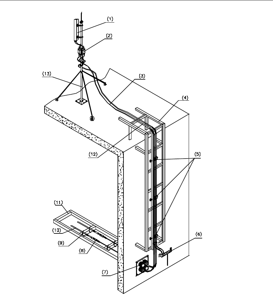
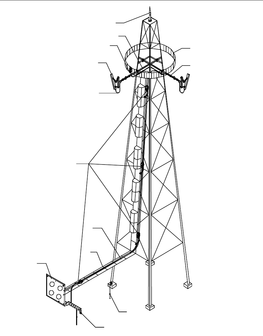
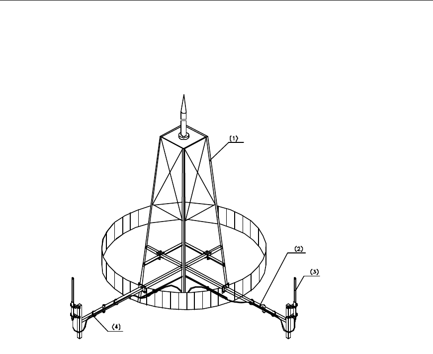
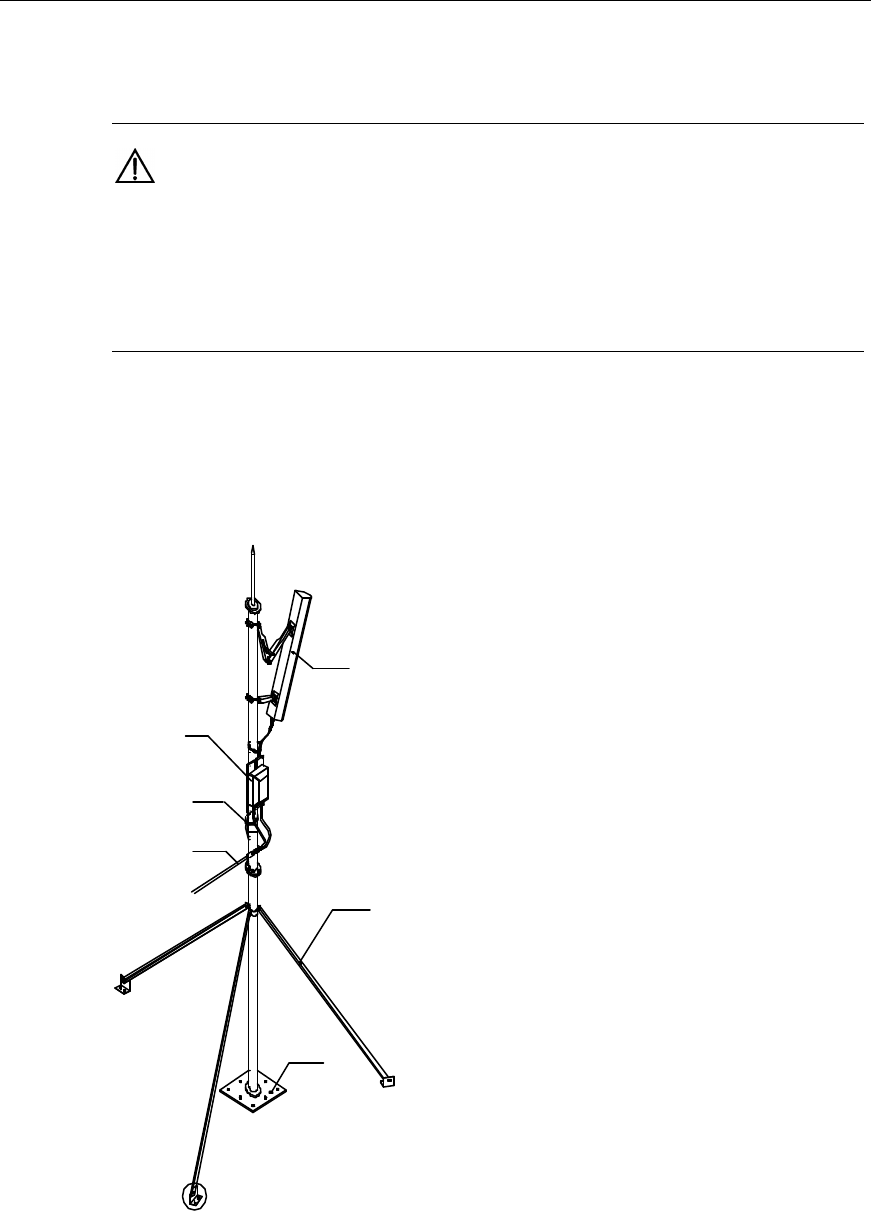
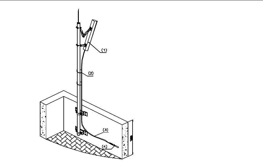
Taking the directional antenna for example, Figure 6-2 and Figure 6-3 show three
typical structures of the antenna & feeder system.
Installation Manual
Airbridge cBTS3612 CDMA Base Station Hardware Installation
6 Installing RF Antenna and Feeder System
6-2
(1) Directional antenna (2) TTA (for band 1900MHz) (3) Outdoor jumper
(4) Outdoor cabling rack (5) Feeder fixing clip (6) Outdoor grounding bar
(7) Feeder encapsulated window (8) Lightning arrester (for band 1900MHz) (9) Binding tape
(10) Indoor jumper (11) Indoor cabling rack (12) Feeder
(13) Antenna stand
Figure 6-2 Typical structure of the antenna & feeder system (with dual-polarization antenna and TTA,
installed on roof)
Installation Manual
Airbridge cBTS3612 CDMA Base Station Hardware Installation
6 Installing RF Antenna and Feeder System
6-3
(11)
(12)
(13)
(1)
(2)
(3)
(4)
(5)
(6)
(7)
(8)
(9)
(10)
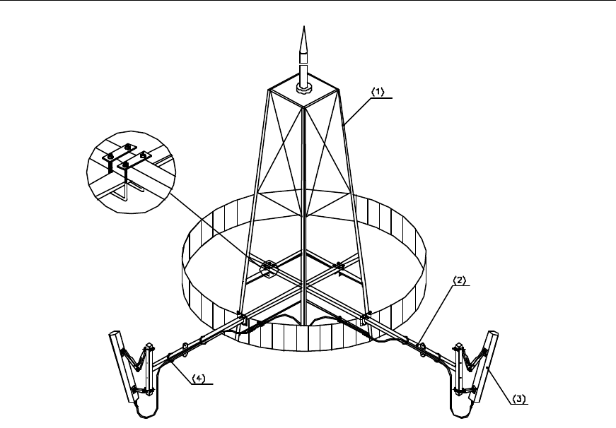
(1) Lightening rod (2) Antenna stand (3) Guard bar on the tower
platform
(4) TTA (for band 1900MHz) (5) Binding tape (6) Directional antenna
(7) Waterproof curve of the jumper (8) Lightening protection
grounding clip of the feeder (9) Feeder
(10) Outdoor cabling rack (11) Feeder encapsulated window (12) Tower grounding body
(13) Outdoor grounding bar
Figure 6-3 Typical structure of the antenna & feeder system (with single-polarization antenna and TTA,
installed on tower platform)
Installation Manual
Airbridge cBTS3612 CDMA Base Station Hardware Installation
6 Installing RF Antenna and Feeder System
6-4
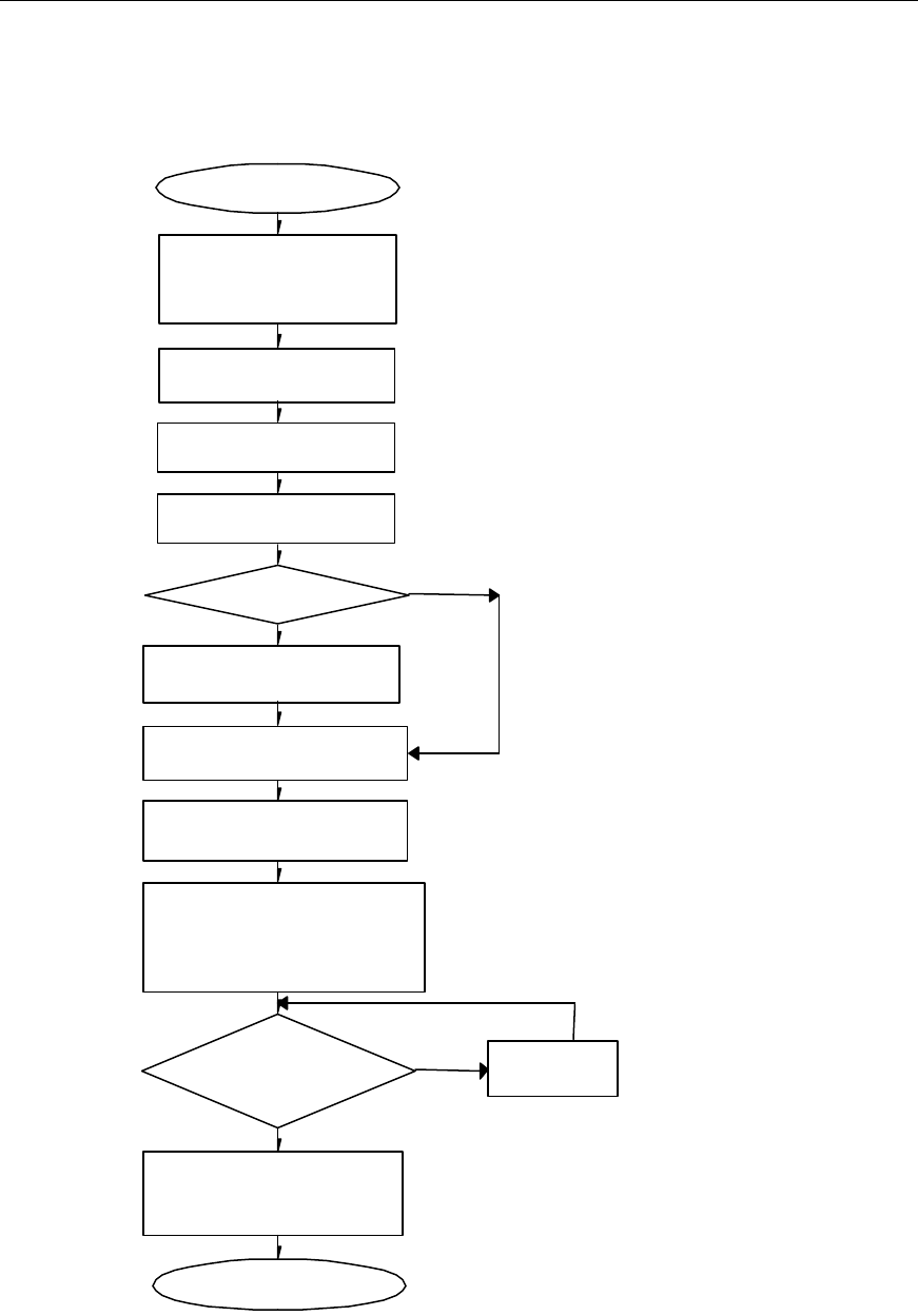
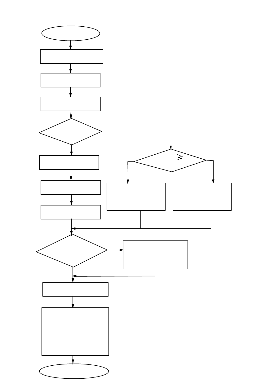
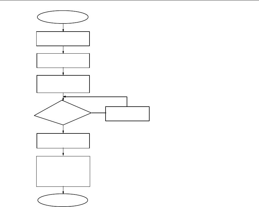
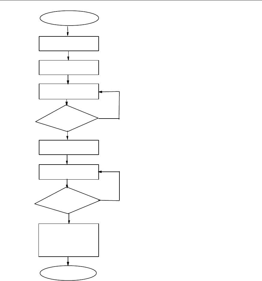
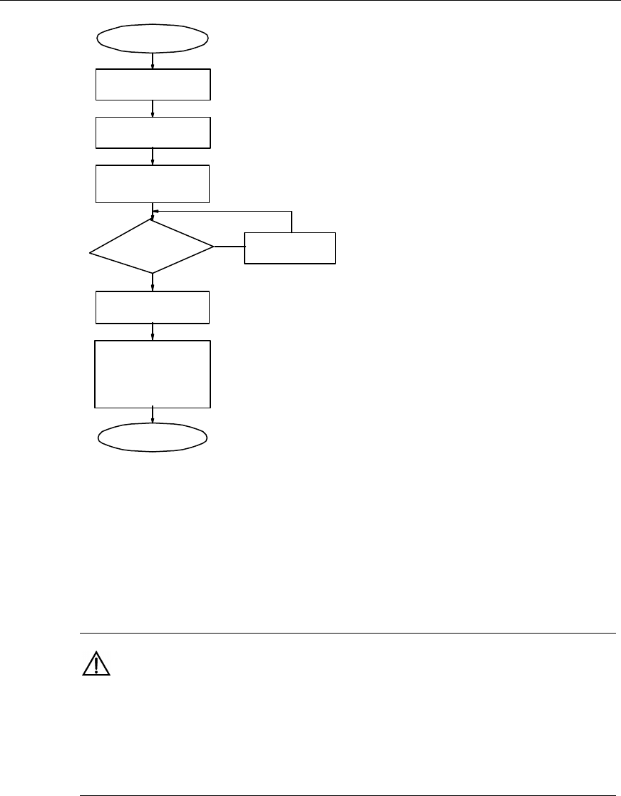
6.1.2 Installation Procedures
The installation procedures are shown in Figure 6-4.
Install TTA and the jumper
from the antenna to TTA
Install the feeder, the jumper and the
grounding clip
Install the feeder encapsulated
window (optional)
Lead the feeder into the room,
install the feeder, lightning arrester and
indoor, jumper (Feeder lightning arrester
should be installed for band 1900MHz)
End
Include TTA?
Y
N
Pass the test on
the antenna &
feeder system?
NFind the problem
and handle it
Y
Inspect the equipment,
prepare the feeder
connectors and assemble
antenna
Install the antenna stand
(optional)
Start
Install the outdoor grounding bar
Install the antenna
Encapsulate the outdoor
connectors and the feeder
encapsulated window
Figure 6-4 Installation procedures of the RF antenna & feeder system

Installation Manual
Airbridge cBTS3612 CDMA Base Station Hardware Installation
6 Installing RF Antenna and Feeder System
6-5
&
Note:
The installation method and procedures may differ according to different installation environment and
different antenna adopted. The project supervisor should arrange the installation neatly as per the
engineering design files, the number of installation personal, the installation environment and the type
of the antenna.
6.2 Installation Preparation
To guarantee the installation quality of the antenna & feeder system, it is suggested
that the antenna & feeder equipment be inspected before the installation. When
installing antennas on the tower, you'd better inspect the equipment, assemble the
antennas and make the feeder connectors on the ground to reduce the workload on
the tower. When installing antennas on the roof, if there is enough space, you can
make the preparations on the roof, or else on the ground or in the room.
6.2.1 Inspecting Antenna & Feeder Equipment
I. Inspecting antennas
Since antennas are easily corrupted during delivery, it’s necessary to inspect the
antenna appearance carefully for any damage, crack or connector breakdown prior
to the installation. If there is any problem, contact the personnel concerned
immediately and put the antenna aside.
If no problem exists as to the antenna appearance, connect the antenna with the
corresponding jumper and test its Voltage Standing Wave Ratio (VSWR) using the
Site Master. Adjust the position and orientation of the antenna during the test, as
they are directly related to the antenna VSWR. If the antenna VSWR is higher than
1.5 in whatever antenna position and orientation, something may be wrong with the
antenna or its connectors. Then inspect it for a second time. If the antenna VSWR is
not higher than 1.5 in all positions, it cannot be determined whether the antenna is
faulty. Upon completion of the antenna installation, re-test the antenna VSWR. If the
antenna and feeder VSWR is still higher than 1.5, the problem certainly lies in the
antenna. Therefore, the antenna should be replaced.
II. Inspecting TTA (for band 1900MHz)
Inspect the appearance for any damage, and then test the VSWR of each port on
the ground. During the test, make sure to connect the ports not under test with the
50W matched terminal load. If not, great test error might be caused.
Installation Manual
Airbridge cBTS3612 CDMA Base Station Hardware Installation
6 Installing RF Antenna and Feeder System
6-6
This test is implemented when the TTA is not powered on. If the test result greatly
differs from the corresponding index, the TTA should be replaced.
&
Note:
Normally, the TTA should be tested when being powered on, for the result is better than when it is not
powered on. However, only the simplified test above mentioned can be implemented for the restricted
field conditions. If conditions permit, test the current of the TTA powered on. If the TTA current is in the
range of 50 ~ 175mA, the VSWR is considered to be suitable.
6.2.2 Making Feeder Connectors
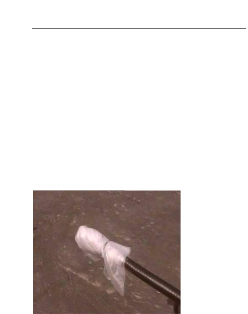
Feeder connectors should be made on site. The connectors of the feeders to be
mounted onto the tower should better be made on the ground, and then be wrapped
up by soft materials such as sponge, and be hoisted, as shown in Figure 6-5. For
feeders, the connectors are of 7/16 DIN & N types. The making method and
procedures for the two types of connectors are the same. Make the connectors in
accordance with the instructions delivered in the packing box. After the making, the
instructions should be well kept for later use.
Figure 6-5 Simple protection of a feeder connector
Installation Manual
Airbridge cBTS3612 CDMA Base Station Hardware Installation
6 Installing RF Antenna and Feeder System
6-7
&
Note:
1) The connectors of the indoor jumpers (1/2”, 7/16 DIN male type) and feeders are normally prepared
on site after introducing the feeders into the room. For details, please refer to section “6.9.10 Installing
Indoor Jumpers”.
2) For outdoor jumpers, the super-flexible jumpers of fixed length are usually applied. There is no need
to make their connectors on site. If any, make the connectors in accordance with the instructions
delivered in the packing box.
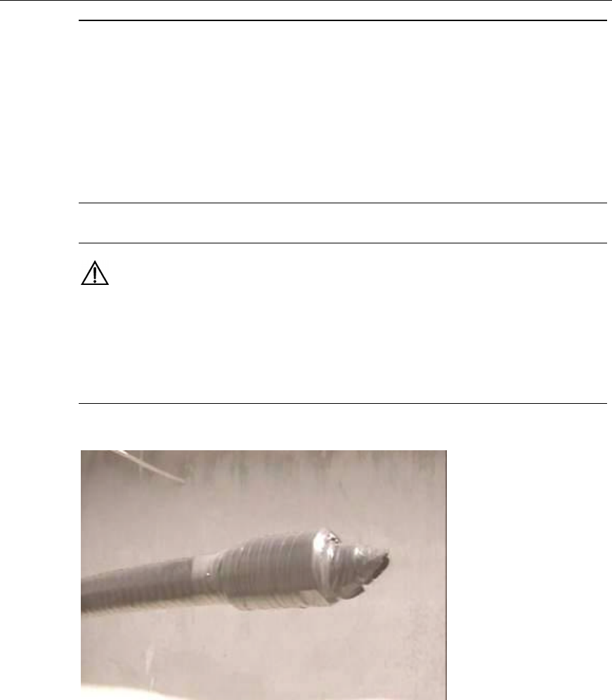
Caution:
If a connector is not completely made in one day or if a comp leted connector is not applied for the
connection of the jumper and feeder soon, the connector should have simple waterproof treatment,
that is, wrap the connector with waterproof tape, as shown in Figure 6-6, or put a plastic bag on the
connector and then wrap the waterproof tape.
Figure 6-6 Simple waterproof treatment of a connector
6.2.3 Assembling Antennas
Assemble the antennas prior to the installation in accordance with the instruction
delivered in the antenna packing box. After the installation, please keep the
instruction well.
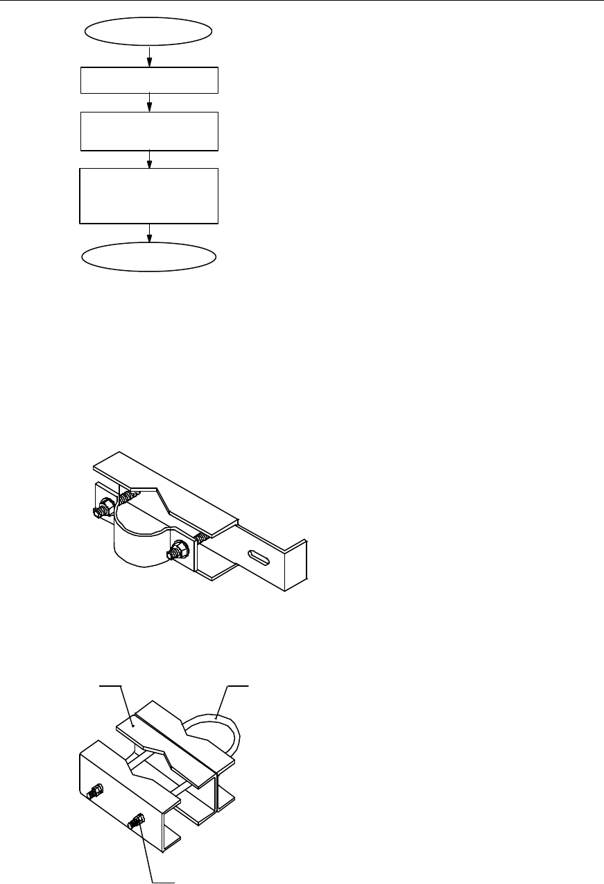
The installation procedures are shown in Figure 6-7.
Installation Manual
Airbridge cBTS3612 CDMA Base Station Hardware Installation
6 Installing RF Antenna and Feeder System
6-8
Start
Install the fixing device
Perform waterproof and
encapsulation treatment to
the connectors
Connect the antenna
with the jumper
End
Figure 6-7 Installation procedures of antenna accessories
I. Assembling omnidirectional antennas
The accessories include antenna fixing clip and jumper. The fixing clips for the
omnidirectional antennas are shown in Figure 6-8 and Figure 6-9.
Figure 6-8 Structure of the fixing clip for omnidirectional antenna (type 1)
(1) (2)
(3)
(1) Connecting pieces of omnidirectional antenna (2) U bolt M12%580 (3) Nut 12
Figure 6-9 Structure of the fixing clip for omnidirectional antenna (type 2)
Installation Manual
Airbridge cBTS3612 CDMA Base Station Hardware Installation
6 Installing RF Antenna and Feeder System
6-9
&
Note:
There are many types of fixing clips for omnidirectional antenna. The two types shown in Figure 6-8
and Figure 6-9 are for reference only. The actual installation should follow the specific conditions. The
following will take the fixing clip shown in Figure 6-8 for example to describe the installation of antenna
accessories.
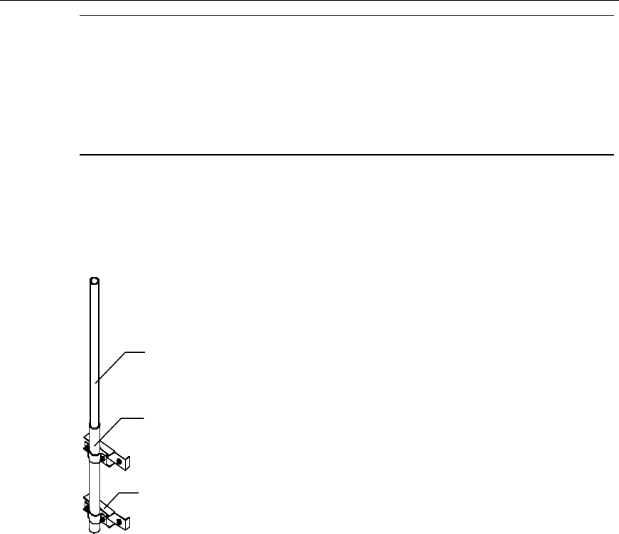
The procedures of assembling such accessories are as follows:
1) Assemble the two fixing clips onto the omnidirectional antenna. The parts
contacting the antenna should be fastened as shown in Figure 6-10.
(1)
(2)
(3)
(1) Omnidirectional antenna (2) Antenna sheathing (3) Fixing clip for the omnidirectional antenna
Figure 6-10 Fixing of the omnidirectional antenna
2) Connect jumpers: Connect the connector of the jumper with that of the antenna
and screw down.
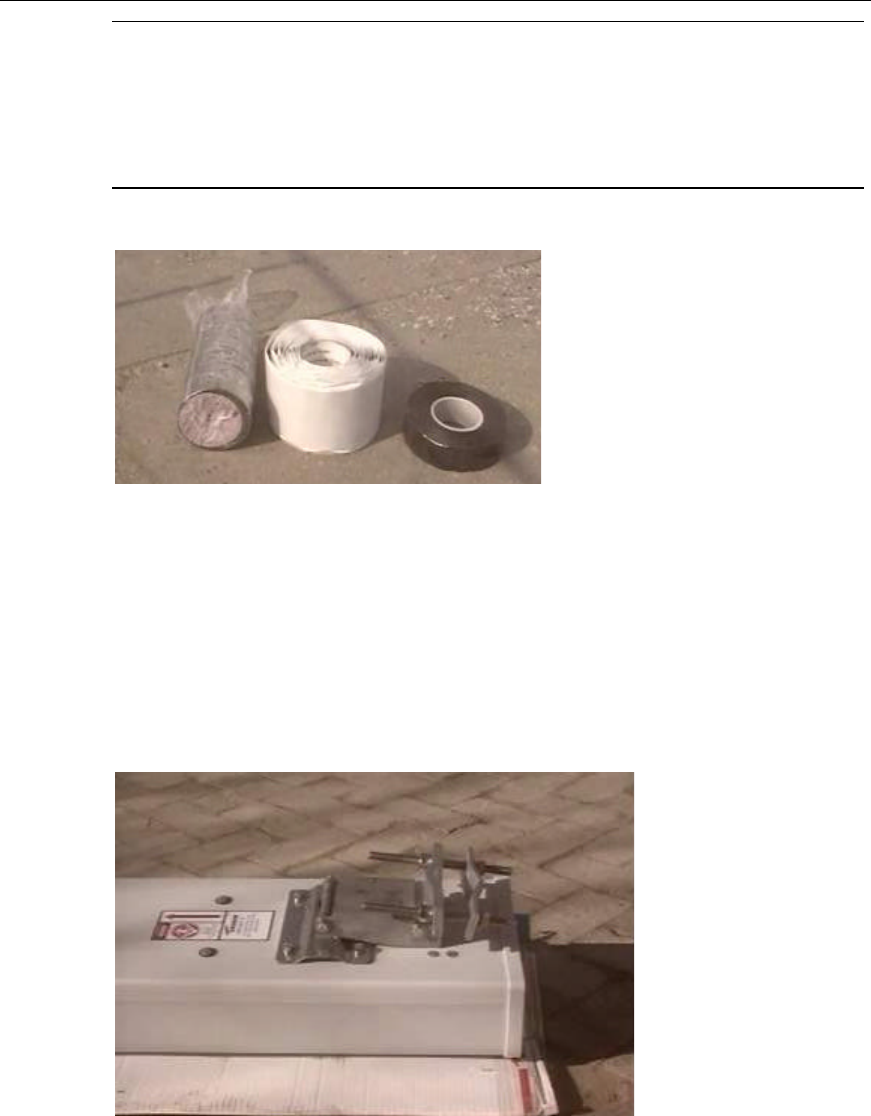
3) Make waterproof & encapsulation treatment for the connector. Wrap it up first
using semi-conductive self-adhesive tape, then waterproof tape and finally
electric insulation tape. Each tape should be wound into three layers, i.e. from
the bottom to the top at the first layer, from the top to the bottom at the second
and then from the bottom to the top at the third. The upper layer of the tape
should overlap one-third width of the layer under. The tape should be tensed to
a proper degree during each winding. All these should satisfy the waterproof
and encapsulation requirements. The three types of tapes are shown in
Figure 6-11.
Installation Manual
Airbridge cBTS3612 CDMA Base Station Hardware Installation
6 Installing RF Antenna and Feeder System
6-10
&
Note:
Steps 2) and 3) can be performed on the tower. During connector capsulation, it is recommended to
wind the electric insulation tape at the first layer and then the semi-conductive self-adhesive tape, so
as to facilitate the dismantling of the tape.
(1) (2) (3)
(1) Electric insulation tape (2) Semi-conductive self-adhesive tape (3) Waterproof tape
Figure 6-11 Waterproof and encapsulation materials for the connectors
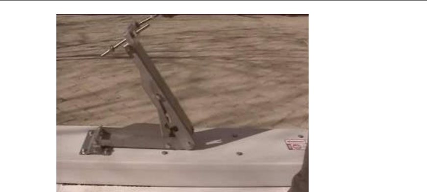
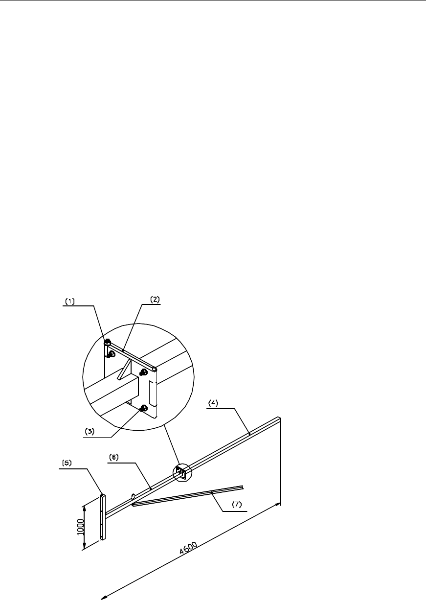
II. Assembling directional antennas
Such accessories include antenna fixing clip (shown in Figure 6-12) and pitch angle
adjusting device (shown in Figure 6-13) and jumper.
Figure 6-12 Fixing clip for the directional antenna
Installation Manual
Airbridge cBTS3612 CDMA Base Station Hardware Installation
6 Installing RF Antenna and Feeder System
6-11
Figure 6-13 Adjusting device for the pitch angle of directional antenna
The procedures of installing such accessories are as follows:
1) Locate the two fixing and adjusting points respectively at the top and bottom of
the antenna according to the identifiers marked on the antenna back. (The
point at the top serves as the pitch angle adjusting point and the one at the
bottom is for fixing the antenna with the stand);
2) Install the accessories into proper places in strict accordance with the
accessory assembly drawings provided by the supplier. (Take care to make
proper and good connection to avoid reworking.) All accessories should be
installed with spring washers and flat washers.
3) Connect jumpers: Connect the connector of the jumper with that of the antenna
and screw down.
4) Make waterproof & encapsulation treatment for the connector between the
antenna and the jumper. (For the specific method, refer to step 3 in section
“6.2.3 I. Assembling omnidirectional antenna”.)
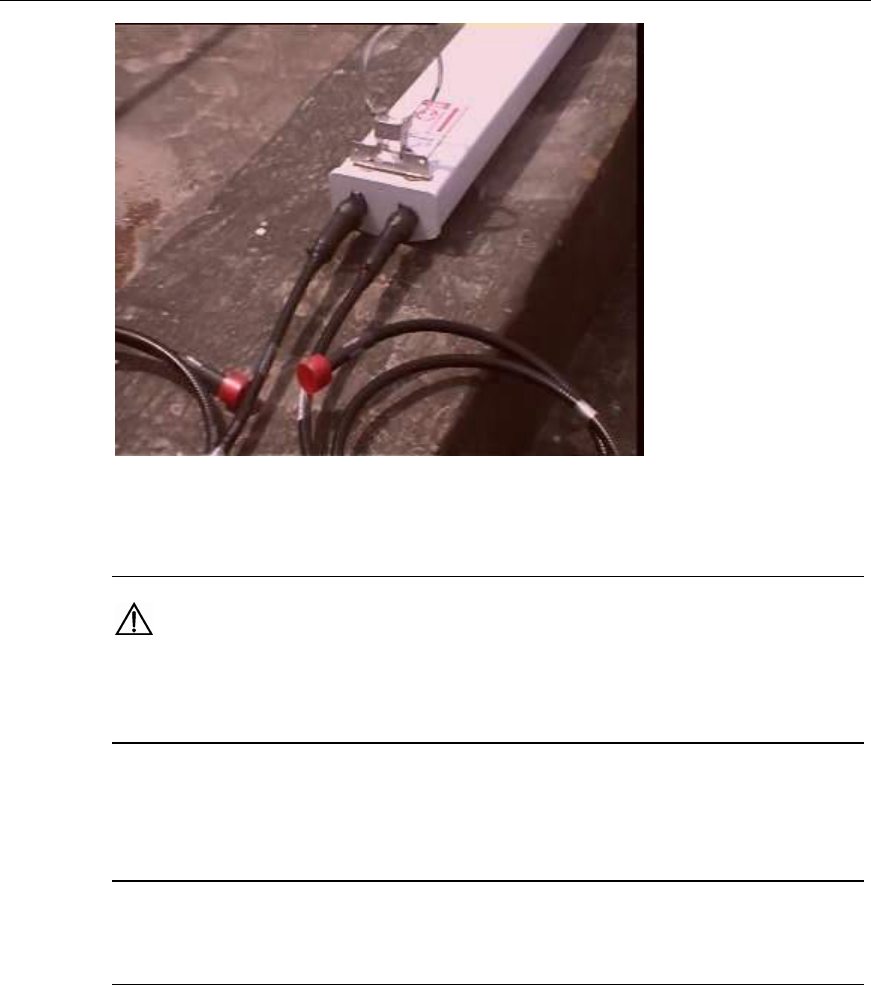
After the connection of the directional antenna with the jumper and the connector
processing, the antenna appearance is shown in Figure 6-14.
Installation Manual
Airbridge cBTS3612 CDMA Base Station Hardware Installation
6 Installing RF Antenna and Feeder System
6-12
Figure 6-14 Appearance of the directional antenna after connection with jumper and connector
processing
Caution:
Both spring washers and flat washers should be mounted for the antenna fixing clip and pitch angle
adjusting device in proper sequence; i.e. the spring washes should be mounted on the flat washers.
6.3 Installing Outdoor Grounding Bar
&
Note:
If there are already outdoor grounding bars meeting the requirements, this section can be skipped.
The outdoor grounding bar serves as the lightning protection-grounding bar.
Generally, it should be installed near the feeder encapsulated window. The optimum
installation position is the place right below the encapsulated window or on the
rainproof wall of the feeder well at the roof. However, during the actual installation
on site, the grounding bar should be located according to the engineering design
drawings.
The structure and the installation procedure of the outdoor grounding bar are the
same as those of the indoor grounding bar. For details, please refer to Appendix C.
Installation Manual
Airbridge cBTS3612 CDMA Base Station Hardware Installation
6 Installing RF Antenna and Feeder System
6-13
6.4 Installing Antenna Stand
The supplier advances the design requirements of the antenna stand, while the
operator takes the opportunity to install the stand. If there have already been stands
meeting the requirements on site, this section can be skipped.
The design requirements and the installation methods of the stand differ according
to different antenna types and installation environment. This section only describes
the installation requirements and procedures of a kind of tower stand and a kind of
rooftop one. As for the stands of other kinds, please refer to the engineering design
documents and the stand instructions.
6.4.1 On Tower Platform
I. Antenna stand structure
There are several structures of the antenna stand for the tower-platform installation.
Take the following one shown in Figure 6-15 for example.
(1)Bolt M12%220 (2) Connecting backplane (3) Bolt M12%45 (4) Expansion link
(5) Fixed link (6) Rotor link (7) Stiffener
Figure 6-15 Structure of the antenna stand on the tower
Installation Manual
Airbridge cBTS3612 CDMA Base Station Hardware Installation
6 Installing RF Antenna and Feeder System
6-14
II. Installation requirements
l The installation plane of the antenna stand should be perpendicular to the level
plane;
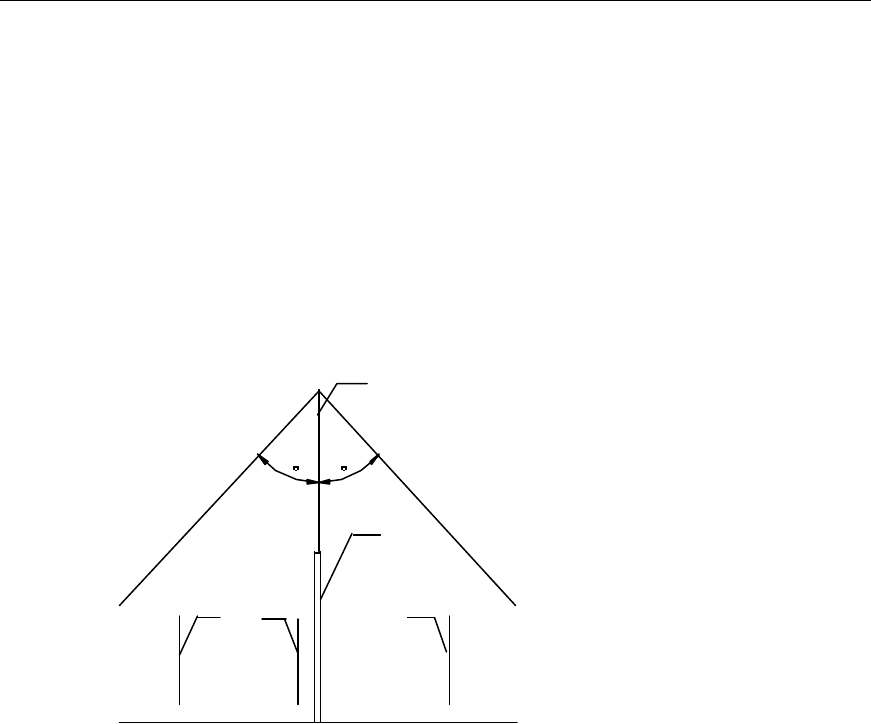
l The mast for the tower lightning rod should be installed separately, satisfying
the requirements for the lightning protection of all antennas. When the antenna
stand is hanged over the tower platform, make sure that the antenna on the
stand is in the lightning protection coverage 300 downward from the top of the
lightning rod, as shown in Figure 6-16. As for the place where the thunderstorm
days are more than 20 days, the lightening protection coverage should be the
area 300 downward from the top of the lightning rod;
30 30
(1)
(2)
(3) (3)(3)
(1) Lightning rod (2) Mast for the lightning rod (3) Antenna
Figure 6-16 Installation of the lightning rod
l Make sure that the antenna stand is installed in the direction in which it does
not affect the Rx & Tx performances and direction adjustment of the directional
antenna;
l Some hoisting measures can be taken for the antenna stand to avoid any
deformation that may result from the long time application;
l The rotor link should be reinforced using a stiffener. The expansion link and the
rotor link should be cut to a length suitable for field installation. The cross
section should be soldered with a cover plate for the waterproof purpose.
l Guarantee security to all soldering joints. There should be no dry joint or open
solder point. The stand should be coated with the antirust aluminum paint and
preferably made of galvanized steel.
III. Installation flow
The installation procedures are shown in Figure 6-17.
Installation Manual
Airbridge cBTS3612 CDMA Base Station Hardware Installation
6 Installing RF Antenna and Feeder System
6-15
Start
Hoist the stand to
the tower
Determine the installation
location of the stand
Fix the stand
End
Figure 6-17 Installation procedures of the antenna stand on the tower
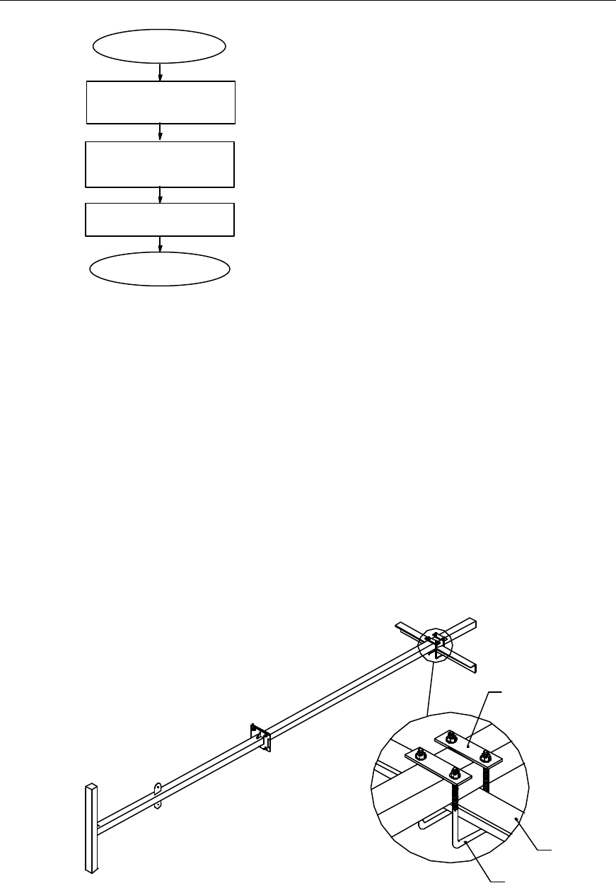
IV. Installation procedures
1) Mount a fixed pulley at the tower top. Hoist the stand to the tower platform
using the fixed pulley and one or two ropes. In addition, use a rope to guide the
rising direction of the stand;
2) Determine the installation location of the antenna stand on the tower platform
according to the antenna & feeder installation drawing in the engineering
design drawings;
3) Hang over the stand out of the tower platform, and fix it onto the tower using a
U fixing clip (including the connecting piece and the U bolt), as shown in
Figure 6-18;
(1)
(2)
(3)
(1) Connecting piece (2) Crossbeam of the tower (3) U bolt
Figure 6-18 Installation of the antenna stand on the tower platform
Installation Manual
Airbridge cBTS3612 CDMA Base Station Hardware Installation
6 Installing RF Antenna and Feeder System
6-16
4) Connect the guardrails on the tower platform with the connecting backplanes
using bolts M12%45.
6.4.2 On Roof
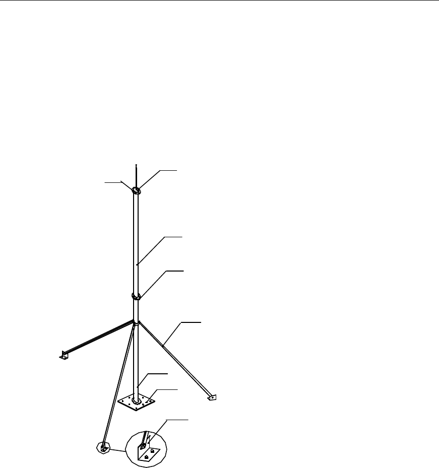
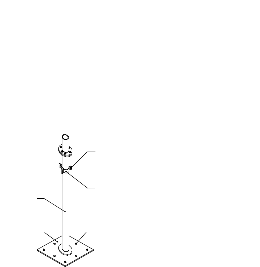
I. Antenna stand structure
There are several structures of the antenna stand on the roof, take the following one
shown in Figure 6-19 for example.
(1)
(2)
(3)
(4)
(5)
(6)
(7)
(8)
(1) Antenna lightning rod (2) Solder point (3) Main supporting post 2
(4) Bolt M10%80 (5) Stiffener (6) Main supporting post 1
(7) The mat of the support post (8) The foot of the support post
Figure 6-19 Structure of the antenna stand on the roof
II. Installation requirements
l The connecting pieces for the stiffener should be installed in places where they
do not impede adjustment of the antenna orientation and pitch angle;
l The antenna stand should be perpendicular to the level plane;
l For installation of directional antennas on the roof, the antenna stand should be
equipped with a lightning rod and the stand should be connected with the
lightning net of the building;

Installation Manual
Airbridge cBTS3612 CDMA Base Station Hardware Installation
6 Installing RF Antenna and Feeder System
6-17
l For installation of omnidirectional antennas on the roof, the antenna stand
generally should not be installed with a lightning rod. The lightning rod should
be installed on a separate stand;
l If the lightening rod is installed on the stand for omnidirectional antennas, it is
required that the antennas should be hanged over out of the stand with a
distance of 1~1.5m;
l The antenna stand and all soldered parts should be coated with the anti-rusting
paint. All soldering joints should be secure. There should be no dry joint or
open solder point.
Installation Manual
Airbridge cBTS3612 CDMA Base Station Hardware Installation
6 Installing RF Antenna and Feeder System
6-18
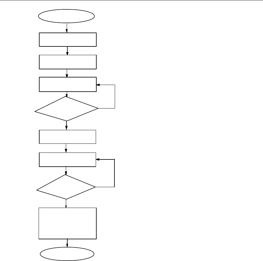
III. Installation flow
Start
Hoist the stand to
the building top
Determine the installation
location of the stand
Solder the lightning rod
Fix the base of the stand
Parapet on the
building top?
N
Y
Install the stiffener
Connect the main
supporting posts 1 & 2
Parapet
1200mm tall?
Y
N
Fix the two fixing points of
the stand respectively on
the wall and on the top
surface of the building
Connect the base of the
stand to the lightning net
of the building using the
lightning connecting bar
Process the soldered parts
End
The stand connected
to the lightning net of
the building?
N
Y
Fix the both fixing
points of the stand
on the wall
Protect the base of the stand,
the anchor of the stiffener as
well as the expansion bolts
used for their connection with
the floor by covering them
with concrete
Figure 6-20 Installation procedures of the antenna stand on the roof
Installation Manual
Airbridge cBTS3612 CDMA Base Station Hardware Installation
6 Installing RF Antenna and Feeder System
6-19
IV. Installation procedures
The antenna stand can be installed on the roof with or without the parapet.
The procedures to install the antenna stand on the roof without the parapet are as
follows:
1) Hoist the antenna stand to the roof;
2) Determine the installation location of the antenna stand on the roof according to
the antenna & feeder installation drawing in the engineering design drawings;
3) Solder the lightning rod onto the main supporting post of the antenna (with their
centerlines on the same straight line);
4) Fix the base of the antenna stand vertically onto the surface of the roof using 8
M10%45 bolts, as shown in Figure 6-21.
(1)
(2)
(3)
(4) (5)
(1) Hex bolt M10%50 (2) Connecting piece of the stiffener (3) Main supporting post 1 of the antenna
(4) Mat of the main supporting post of the antenna (5) Expansion bolt M10%50
Figure 6-21 Structure and installation of the antenna stand base
5) The main supporting post should be reinforced using the stiffener. It depends
on the length of the main supporting post to decide the length of the stiffener.
As shown in Figure 6-19, connect the stiffener with the main supporting post
securely using the connecting pieces of the stiffener. Connect the anchor onto
the stiffener. Fix each anchor of the stiffener onto the surface of the roof using
two expansion bolts M10%45. Make all efforts to ensure that no deformation
may occur to the stiffener;
6) As shown in Figure 6-19, connect the main supporting posts 1 and 2 of the
stand securely using six bolts M10%80;
Installation Manual
Airbridge cBTS3612 CDMA Base Station Hardware Installation
6 Installing RF Antenna and Feeder System
6-20
7) For the antenna stand not soldered with the outdoor cabling rack at the roof or
soldered with the cabling rack unconnected with the lightning net of the building,
connect the base of it with the lightning net of the building using the lightning
connecting bar. (The lightning connecting bar serves as the mounting piece of
the outdoor cabling rack);
8) The antenna stand base and all soldered parts should be coated with the anti-
rusting paint;
9) The base of the antenna stand at the roof, the anchor of the stiffener and the
expansion bolts used for their connection with the floor should be covered with
concrete for protection.
&
Note:
Generally no lightening rod is installed on the stand with omnidirectional antennas. Instead, the
lightning rod should be installed on a separate stand.
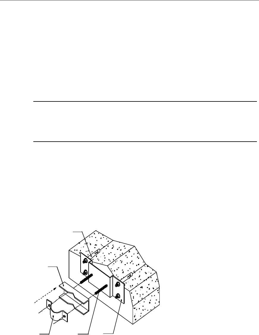
The procedures to install the antenna stand onto the roof with the parapet are as
follows:
If the roof is enclosed with parapet, it is not easy to install the antenna stand onto
the surface of the roof. In this case, the antenna stand can be installed on the wall.
Figure 6-22 shows how to mount the fixing clip of the antenna stand onto the
parapet.
(1)
(2)
(3) (4) (5)
(1) Expansion bolt M12%120 (2) V connecting piece (3) 180o connecting piece
(4) Bolt M12%140 (5) Fixing plate
Figure 6-22 Installation of the fixing clip of the antenna stand onto the parapet
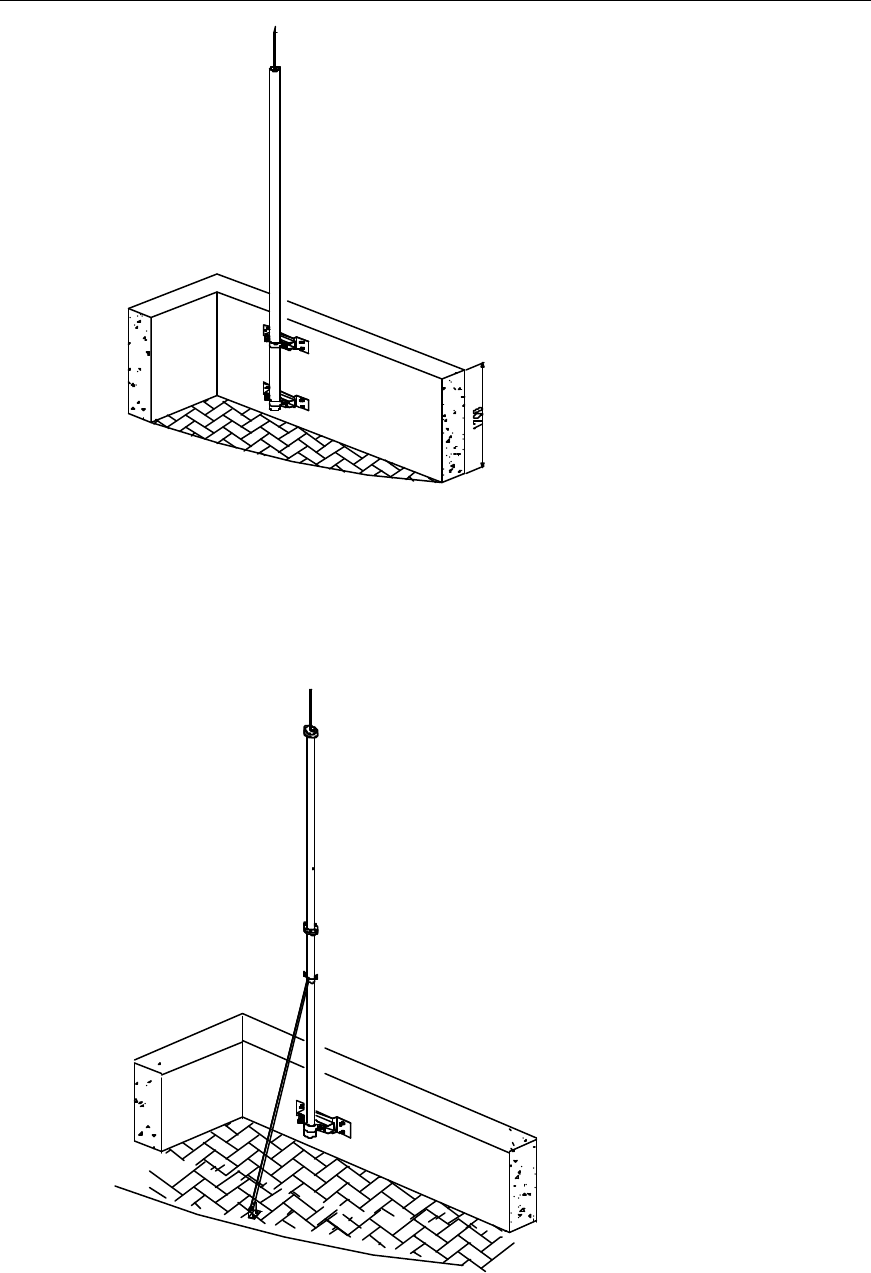
When the parapet is 1200mm or higher, both fixing points of the stand can be fixed
onto the parapet using expansion bolts, as shown in Figure 6-23.
Installation Manual
Airbridge cBTS3612 CDMA Base Station Hardware Installation
6 Installing RF Antenna and Feeder System
6-21
Figure 6-23 Fixing the antenna stand onto the parapet (1200mm or higher)
When the parapet is shorter than 1200mm, fix one fixing point of the main
supporting post onto the parapet using expansion bolts and the other onto the
surface of the roof, as shown in Figure 6-24.
Figure 6-24 Fixing the antenna stand onto the parapet (shorter than 1200mm)
Installation Manual
Airbridge cBTS3612 CDMA Base Station Hardware Installation
6 Installing RF Antenna and Feeder System
6-22
6.5 Installing Antennas on Tower Platform
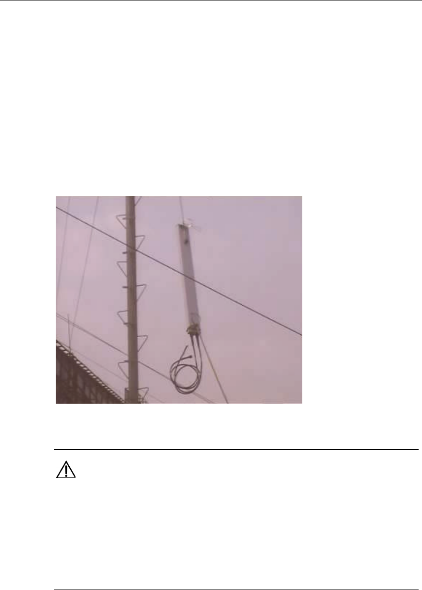
6.5.1 Hoisting Antennas and Other Articles
Mount a fixed pulley at the tower top, thrill a rope through the pulley, and knot the
rope at each end of the antenna. Then the personnel on the tower and on the
ground cooperate in hoisting the antenna to the location (the antenna stand) where
the antenna is to be fixed. During the hoisting, the personnel on the tower should
pull up the rope and the personnel on the ground should keep pulling the rope to
avoid any damage to the antenna due to possible collision with the building or the
tower. Figure 6-25 shows how to hoist the directional antenna.
Figure 6-25 Hoisting the directional antenna
Caution:
1) During the hoisting, make sure there is no person standing right below the hoisted object. The
personnel working outside the tower platform should wear safety belts and harnesses.
2) Small metal articles such as the fixing piece and the spanner should be packed in the tool bag and
then be hoisted.
3) The hoisted articles should be put in the place where they do not slide easily. Beside, safety
treatments should be made.
Installation Manual
Airbridge cBTS3612 CDMA Base Station Hardware Installation
6 Installing RF Antenna and Feeder System
6-23
6.5.2 Installing Omnidirectional Antennas
The installation of the omnidirectional antennas onto the tower platform is shown in
Figure 6-26
(1) Tower (2) Antenna stand at the tower top
(3) Omnidirectional antenna (4) Cable tie
Figure 6-26 Installing the omnidirectional antenna onto the tower platform
I. Installation requirements
l When installing an omnidirectional antenna onto the tower, make sure that the
antenna lies in the protection coverage of the lightning rod and that the antenna
is at least 2m away from the tower body;
l For isolation of omnidirectional antenna, please refer to Appendix E. The
specific installation should comply with the engineering documents of the time.
l The antenna axis should be perpendicular to the level plane and the possible
error should be less than ±1°;
l As for the omnidirectional antenna, the transmit antenna and receive antenna
can be installed on the same stand as shown in Figure 6-27, or be installed
separately. The specific installation location should be determined according to
the engineering design drawings;
l Waterproof curve should be made for the antenna jumper.
Installation Manual
Airbridge cBTS3612 CDMA Base Station Hardware Installation
6 Installing RF Antenna and Feeder System
6-24
(1) Omnidirectional antenna (2) Antenna fixing clip (3) Fixing bar
Figure 6-27 Vertical installation of the omnidirectional antennas
II. Installation procedures
The installation procedures are shown in Figure 6-28.
Installation Manual
Airbridge cBTS3612 CDMA Base Station Hardware Installation
6 Installing RF Antenna and Feeder System
6-25
Start
Fix the antenna onto
the stand
Y
N
Check the verticality of
the antenna
Make the waterproof
curve for the antenna
jumper, bind and
distribute the jumper
End
Decide the installation
location of the antenna
The verticality
error<±1°?
Adjust and fix the
antenna again
Tighten up the antenna
Figure 6-28 Installation procedures of the omnidirectional antenna
1) Decide the installation location of the antenna according to the engineering
design drawings;
2) Place the feeding point of the antenna facedown and the sheathing near the
main supporting post of the stand, then fix the antenna to the fixing bar of the
stand, as shown in the left part of Figure 6-29;
Installation Manual
Airbridge cBTS3612 CDMA Base Station Hardware Installation
6 Installing RF Antenna and Feeder System
6-26
(7)
(1) Omnidirectional antenna (2) Antenna fixing clip (3) Fixing bar (4) Connecting piece
(5) Crossbeam of the tower (6) U bolt (7) Waterproof curve of the jumper
Figure 6-29 Installation of the omnidirectional antenna
Caution:
The top end of the sheathing should be at the same height as the stand top or slightly higher than it.
The transmission part of the antenna should be higher than the top of the fixing bar. The fixing
tightness should be right enough for bearing and wind resistance. Looseness may cause loose
connection while too much tension may damage the antenna sheathing.
3) Use an angular tester to check whether the antenna axis is perpendicular to the
horizontal plane. If the error is equal to or more than !1°, adjust the antenna
and re-fasten it;
4) Tighten up the antenna till the antenna cannot be moved by any hand pull or
push;
5) Make the waterproof curve of the jumper, distribute and bind the jumper along
the cross bar of the stand using black cable ties, and cut off the extra tail of the
cable tie;
Installation Manual
Airbridge cBTS3612 CDMA Base Station Hardware Installation
6 Installing RF Antenna and Feeder System
6-27
Caution:
Jumpers should be bent in a natural manner. The bending radius should be 20 times longer than the
jumper diameter. The cable ties should be wound in the same way. When cutting the cable ties, there
should be an allowance of 5 ~ 10mm left lest the cable ties fall off the jumper due to temperature
change.
6) Hang over the rotor link of the stand installed with antenna out of the tower
platform. Use bolts to fix the connecting panel.
&
Note:
If there is no guardrail on the tower platform, set up an access board across the arms of two stands
using a secure wooden board so as to form a working platform for the installation personnel. This
further guarantees the security to the operating personnel fixing the antenna and the connection of
TTA with the feeder. After fixing the antenna and the connection of TTA with the feeder on one side,
change the location of the wooden board on the stand arms to fix other antennas and the connection
of TTA with other feeders.
6.5.3 Installing Directional Antennas
The installation of the directional antennas onto the tower platform is shown in
Figure 6-30.
Installation Manual
Airbridge cBTS3612 CDMA Base Station Hardware Installation
6 Installing RF Antenna and Feeder System
6-28
(1) Tower (2) Antenna stand on the top of the tower (3) Directional antenna (4) Cable tie
Figure 6-30 Installation of the directional antenna on the tower platform
I. Installation requirements
l The antenna should be in the protection coverage of the lightning rod. No
interference from the tower structure should exist in the forward direction of the
antenna. The length of the antenna protruding from the tower platform should
be no less than 1m;
l For isolation of directional antenna, please refer to Appendix E. The specific
installation should comply with the engineering documents of the time.
l Waterproof curve should be made for the antenna jumper.
II. Installation procedures
The installation procedures are shown in Figure 6-31.
Installation Manual
Airbridge cBTS3612 CDMA Base Station Hardware Installation
6 Installing RF Antenna and Feeder System
6-29
Start
Fix the antenna onto
the stand
Error of the azimuth
angle ≤5°?
N
Adjust the azimuth
angle of the antenna
Decide the installation
direction of the antenna
Error of the pitch
angle ≤0.5°?
Y
N
Make the waterproof
curve for the jumper,
distribute and bind
the jumpers
End
Y
Fasten the antenna
Adjust the pitch angle
Figure 6-31 Installation procedures of the directional antenna
Installation Manual
Airbridge cBTS3612 CDMA Base Station Hardware Installation
6 Installing RF Antenna and Feeder System
6-30
Installation details:
1) Decide the installation direction of the antenna according to the project
installation drawings;
2) Fix the antenna onto the main supporting post. The fixing tightness should be
right enough for bearing and wind resistance. Looseness may cause loose
connection while too much tension may damage the antenna sheathing;
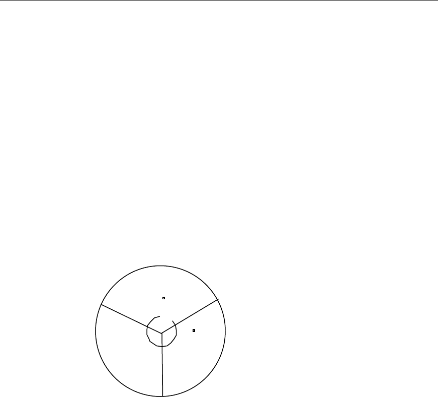
3) Adjust the azimuth angle of the antenna. Determine the azimuth angle
according to the engineering design documents and determine it using the
compass. Normally, sector 1 is in the north. Sector 2 lies in the clockwise 120°
direction and sector 3 in the next clockwise 120° direction, as shown in
Figure 6-32. By turning the antenna slightly, the personnel can adjust the
azimuth angle till it satisfies the design index value. Usually, the error of the
azimuth angel should be [5°;
Sector 1
North
120
120
Sector 2
Sector 3
Figure 6-32 Relationship between the azimuth angle of the directional antenna and the sector
4) Tighten up the lower fixing clip of the antenna till it cannot be moved by any
hand pull or push;
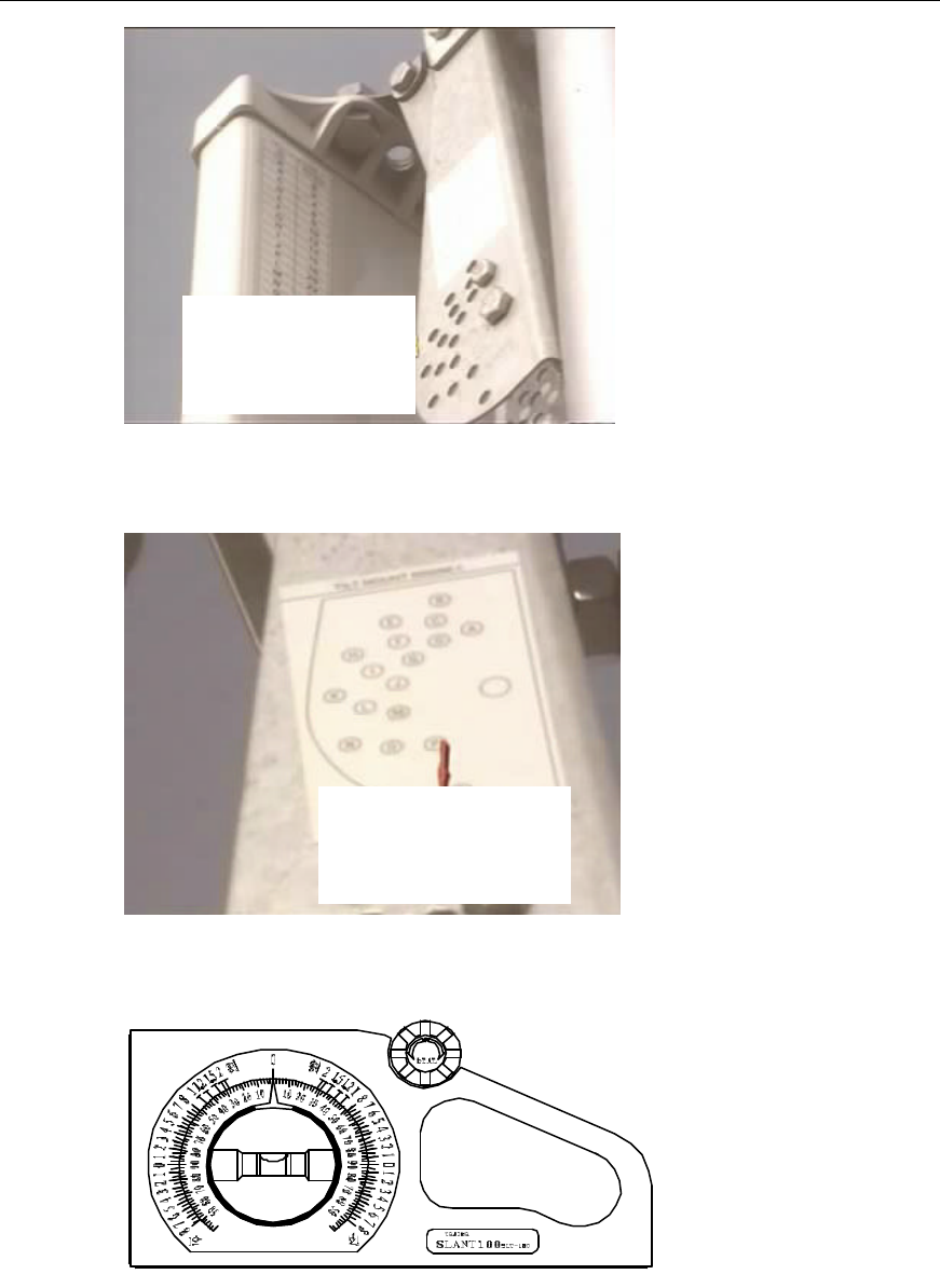
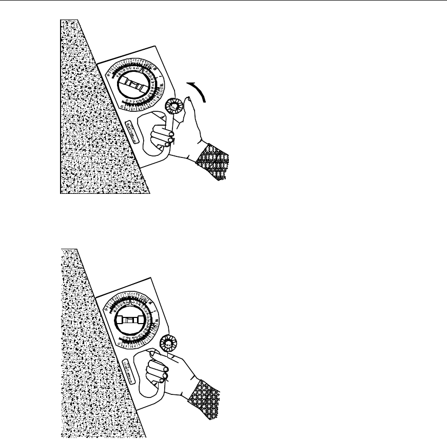
5) Adjust the pitch angle of the antenna. If the mounting hole of each directional
antenna has its corresponding pitch angle, the antenna can be installed directly
into the mounting hole as shown in Figure 6-33 and Figure 6-34. However, the
supporting post should be kept perpendicular to the ground during the
installation. For other antennas, the pitch angles are adjusted in the following
way:
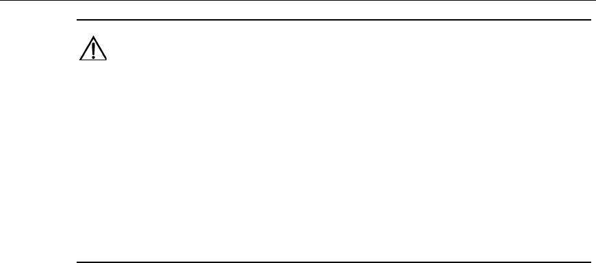
l Decide the pitch angle of the antenna using the angle display, as shown in
Figure 6-35 and Figure 6-36;
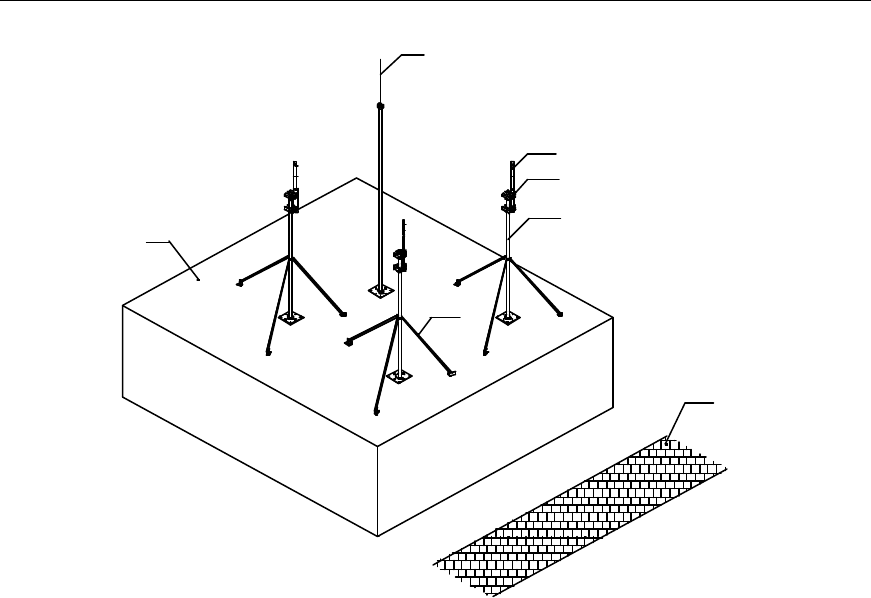
l By turning the antenna slightly, adjust the pitch angle till it satisfies the
engineering design index, as shown in Figure 6-37. Usually, the error of the
pitch angle is required to be Ÿ 0.5°;
l Tighten up the upper fixing clip of the antenna till it cannot be moved by any
hand pull or push;
Installation Manual
Airbridge cBTS3612 CDMA Base Station Hardware Installation
6 Installing RF Antenna and Feeder System
6-31
Get the mounting hole
number according to the
antenna pitch angle.
Figure 6-33 Directional antenna with the mounting hole corresponding to the pitch angle
Get the mounting hole
according to the mounting
hole number.
Figure 6-34 Directional antenna with the mounting hole corresponding to the pitch angle
Figure 6-35 Angle display
Installation Manual
Airbridge cBTS3612 CDMA Base Station Hardware Installation
6 Installing RF Antenna and Feeder System
6-32
Figure 6-36 Inclinometer before adjusting the pitch angle of the antenna
Figure 6-37 Inclinometer after adjusting the pitch angle of the antenna
6) Make the waterproof curve of the antenna jumper, distribute and bind the
jumpers along the cross bar of the stand using the black cable tie, and cut off
the extra tail of the cable tie;
7) Hang over the rotor link of the stand installed with the antenna out of the tower
platform, and use bolts to fix the connecting panel.
Installation Manual
Airbridge cBTS3612 CDMA Base Station Hardware Installation
6 Installing RF Antenna and Feeder System
6-33
Caution:
1) Take care to protect the installed jumpers from damage during the course of installing and adjusting
the antenna;
2) When using the compass, keep it away from the tower and other iron and steel objects. Be careful
of any geomagnetic abnormality that can interfere in the accurate operation of the compass;
3) The jumpers should bend in a natural manner. The bending radius should be 20 times longer than
the jumper diameter;
4) The cable ties should be wound in the same way. When cutting the cable ties, there should be an
allowance of 5 ~ 10mm left lest the cable ties fall off the jumper due to temperature change.
6.6 Installing Antenna on Roof
6.6.1 Carrying (hoisting) Antennas and Other Articles
Carry (hoist) antennas and other articles to the roof. Be careful to keep the articles
from collision in the process. The method and the caution for hoisting are the same
as those for hoisting on the tower platform. For details, please refer to section “6.5.1
Hoisting Antenna”.
6.6.2 Installing Omnidirectional Antennas
The installation of the omnidirectional antennas onto the stands on the roof is shown
in Figure 6-38.
Installation Manual
Airbridge cBTS3612 CDMA Base Station Hardware Installation
6 Installing RF Antenna and Feeder System
6-34
(1)
(2)
(3)
(4)
(5)
(6)
(7)
(1) Antenna lightning rod (2) Antenna (3) Fixing clip for the omnidirectional antenna
(4) Main supporting post (5) Road (6) Stiffener (7) Roof
Figure 6-38 Installing the omnidirectional antenna onto the stand at the roof
I. Installation requirements
The requirements of the isolation degree and the installation interval of the
omnidirectional antennas are the same as those for installing the omnidirectional
antennas on the tower platform. For details, please refer to section “6.5.2 I.
Installation requirements”. Besides, the following points should be noted:
l Keep away from the defilades to avoid the signal blind area when installing
antennas;
l If there is no lightening rod on the top of the antenna stand, install a lightening
rod separately and make sure the distance between omnidirectional antennas
and the lightening rod should be no less than 2.5m. Besides, the antennas
should be in the lightning protection coverage 30° downward from the top of the
lightning rod;
l If there is lightening rod on the top of the antenna stand, the distance for
hanging over the stand should be 1 ~ 1.5m.
II. Installation procedures
The installation procedures are shown in Figure 6-39.
Installation Manual
Airbridge cBTS3612 CDMA Base Station Hardware Installation
6 Installing RF Antenna and Feeder System
6-35
Start
Fix the antenna onto
the stand
Y
N
Check the verticality of
the antenna
Make the waterproof
curve for the antenna
jumper, bind and
distribute the jumper
End
Decide the installation
location of the antenna
The verticality
Error < !1°?Adjust and fix the
antenna again
Tighten up the antenna
Figure 6-39 Installation procedures of the omnidirectional antenna on the roof
1) Decide the installation location of the antenna according to the engineering
design drawings;
2) Place the feeding point of the antenna facedown and the sheathing near the
main supporting post of the stand, then fix the antenna to the fixing bar of the
stand;
Caution:
The top end of the sheathing should be at the same height as the stand top or slightly higher than it.
The transmission part of the antenna should be higher than the top of the fixing bar. The fixing
tightness should be right enough for bearing and wind resistance. Looseness may cause loose
connection while too much tension may damage the antenna sheathing
3) Use an angular tester to check whether the antenna axis is perpendicular to the
horizontal plane. If the error is equal to or more than !1°, adjust it and re-fasten
it;
4) Tighten up the antenna till the antenna cannot be moved by any hand pull or
push;
Installation Manual
Airbridge cBTS3612 CDMA Base Station Hardware Installation
6 Installing RF Antenna and Feeder System
6-36
5) Make the waterproof curve of the jumper, distribute and bind the jumper along
the cross bar of the stand using black cable ties, and cut off the extra tail of the
cable ties.
Caution:
The jumpers should bend in a natural manner. The bending radius should be 20 times longer than the
jumper diameter. The cable ties should be wound in the same way. When cutting the cable ties, there
should be an allowance of 5 ~ 10mm left lest the cable ties fall off the jumper due to temperature
change.
6.6.3 Installing Directional Antennas
The installation is shown in Figure 6-40 and Figure 6-41.
(1)
(2)
(3)
(4)
(5)
(6)
(1) Antenna (2) TTA (for band 1900MHz) (3) Cable tie
(4) Feeder (5) Stiffener (6) Mat of the supporting post
Figure 6-40 Installation of the directional antenna at the roof (without the parapet, with TTA)
Installation Manual
Airbridge cBTS3612 CDMA Base Station Hardware Installation
6 Installing RF Antenna and Feeder System
6-37
(1) Antenna (2) Cable tie (3) Jumper (4) Feeder
Figure 6-41 Installation of the directional antenna at the roof (with parapet 1200mm or higher)
I. Installation requirements
The requirements of the isolation degree and the installation interval of the
directional antennas are the same as those for installing the directional antennas on
the tower platform. For details, please refer to section “6.5.3 I. Installation
requirements”. Besides, the following points should be noted:
l Keep away from the defilades to avoid the signal blind area when install
antennas;
l The stand must be installed with lightening rod.
II. Installation procedures
The installation procedures are shown in Figure 6-42.
Installation Manual
Airbridge cBTS3612 CDMA Base Station Hardware Installation
6 Installing RF Antenna and Feeder System
6-38
Start
Fix the antenna onto
the stand
Error of the azimuth
angle ≤5°?
N
Adjust the azimuth
angle of the antenna
Decide the installation
direction of the antenna
Error of the pitch
angle ≤0.5°?
Y
N
Make the waterproof
curve for the jumper,
distribute and bind
the jumpers
End
Y
Fasten the antenna
Adjust the pitch angle
Figure 6-42 Installation procedures of the directional antenna on the roof
1) Decide the installation direction of the antenna according to the project
installation drawings;
2) Fix the antenna onto the main supporting post. The fixing tightness should be
right enough for bearing and wind resistance. Looseness may cause loose
connection while too much tension may damage the antenna sheathing;
3) Adjust the azimuth angle of the antenna. The way of adjusting is the same as
that of installing directional antenna onto tower platform, please refer to step 3
in section “6.5.3 II. Installation procedures”. Usually, the error of the azimuth
angel should be Ÿ 5°;
4) Tighten up the lower fixing clip of the antenna till it cannot be moved by any
hand pull or push;
Installation Manual
Airbridge cBTS3612 CDMA Base Station Hardware Installation
6 Installing RF Antenna and Feeder System
6-39
5) Adjust the pitch angle of the antenna. The way of adjusting is the same as that
of installing directional antenna onto tower platform, please refer to step 5 in
section “6.5.3 II. Installation procedures”. Usually the error of the pitch angle is
required to be Ÿ 0.5°;
6) Make the waterproof curve of the antenna jumper, distribute and bind the
jumpers along the cross bar of the stand using the black cable tie, and cut off
the extra tail of the cable tie.
Caution:
1) Take care to protect the installed jumpers from damage during the course of installing and adjusting
the antenna;
2) When using the compass, keep it away from the tower and other iron and steel objects. Be careful
of any geomagnetic abnormality that can interfere in the accurate operation of the compass;
3) The jumpers should bend in a natural manner. The bending radius should be 20 times longer than
the jumper diameter;
4) The cable ties should be wound in the same way. For the cuttings, there should be an allowance of
5 ~ 10mm left lest the tape falls off the jumper due to temperature changes.
Installation Manual
Airbridge cBTS3612 CDMA Base Station Hardware Installation
6 Installing RF Antenna and Feeder System
6-40
6.7 Installing Tower-top Amplifier
&
Note:
If it’s no need to install the TTA, skip this section.
6.7.1 General
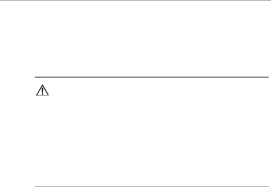
I. TTA outline and structure
The outline and structure of TTA is shown in Figure 6-43.
Figure 6-43 TTA outline
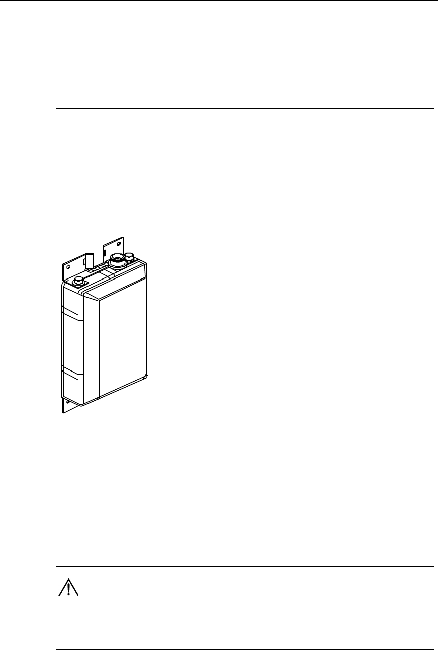
II. Cable connection relationship
The TTA has two RF interfaces. Both are of the 7/16DIN (female) type. One is for
the connection with the RX antenna (normally marked with “ANT”). Another is for the
connection with BTS (normally marked with “BTS”). It is connected to the receiving
RF interface (7/16DIN connector) at the BTS cabinet top through jumper and feeder.
Caution:
As for some TTAs, the two connectors ANT and BTS lie on different sides, while for others, they are on
the same side.
Installation Manual
Airbridge cBTS3612 CDMA Base Station Hardware Installation
6 Installing RF Antenna and Feeder System
6-41
6.7.2 Installing TTA
I. Installation location
The TTA should be installed near the antenna.
l For installation on the tower, the TTA should be installed onto the guardrail of
the tower platform.
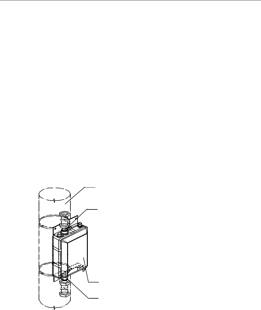
l For installation at the roof, the TTA should be installed onto the main
supporting post and below the antenna, as shown in Figure 6-40. The TTA can
also be installed onto the parapet at the roof alternatively.
II. Installation procedures
For the installation of TTA, cooperative efforts are required lest the TTA should fall
off the tower or the roof.
1) Hoist the TTA together with the accessories onto the tower or the roof;
2) Orient the TTA in the right direction and fix it to the specified location as shown
in Figure 6-44 and Figure 6-45;
(1)
(3)
(2)
(4)
(1) Main supporting post (2) RF interface ANT (3) TTA (4) RF interface BTS
Figure 6-44 Installing the TTA onto the main supporting post
Installation Manual
Airbridge cBTS3612 CDMA Base Station Hardware Installation
6 Installing RF Antenna and Feeder System
6-42
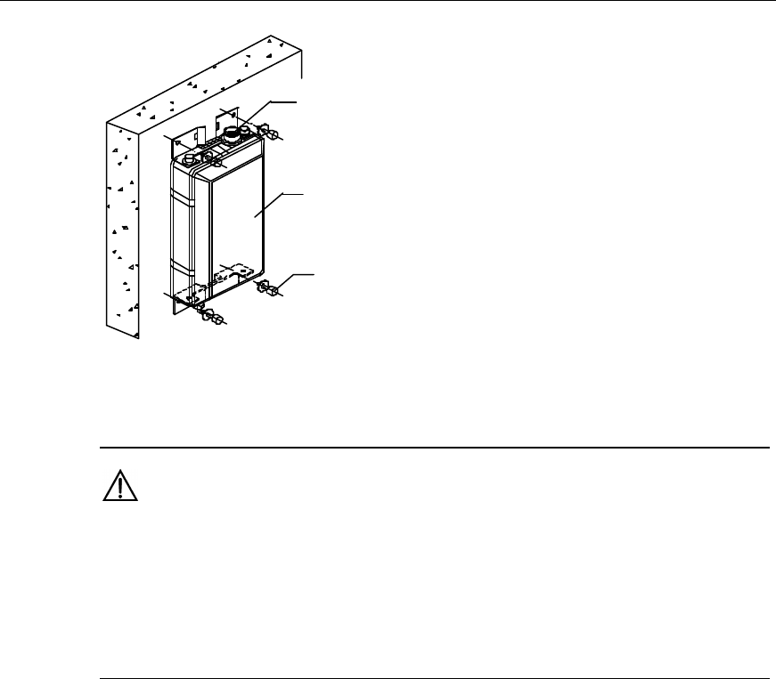
(1)
(2)
(3)
(1) RF interface ANT (2) TTA (3) Explosion bolt
Figure 6-45 Installing the TTA on the wall on the roof
Caution:
1) For the TTA with connectors on different sides, ANT (the connector to the antenna) should be
extended upward and BTS (the connector to cBTS3612) downward. The grounding pole is used for
grounding.
2) For the TTA with connectors on the same side, both ANT (the connector to the antenna) and BTS
(the connector to cBTS3612) should be extended downward.
3) Connect the grounding pole of the TTA to the grounding point securely using
grounding cables.
6.7.3 Connecting Jumpers between Antenna and TTA
The appearance of jumpers connected between the antenna and TTA is shown in
Figure 6-46. Usually, the jumper is 2.5m long, as shown in Figure 6-47.
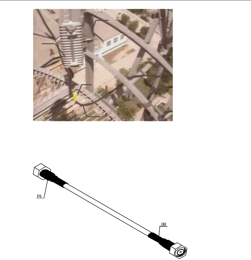
Installation Manual
Airbridge cBTS3612 CDMA Base Station Hardware Installation
6 Installing RF Antenna and Feeder System
6-43
(1)
(2)
(3)
(4)
(1) Guardrails on the tower platform (2) TTA (3) Jumper label (4) Waterproof curve of the jumper
Figure 6-46 Jumper connection between the antenna and TTA
(1) To TTA (2) To the antenna
Figure 6-47 Jumper between the antenna and TTA
Installation procedures are as follows:
1) Screw the jumper connector onto the TTA;
2) Make the waterproof curve of the jumper. The jumpers should be bent in a
natural manner. The bending radius should be 20 times longer than the jumper
diameter;
3) Bind the jumpers and label them. The label should be attached 100mm away
from the end of the jumper.
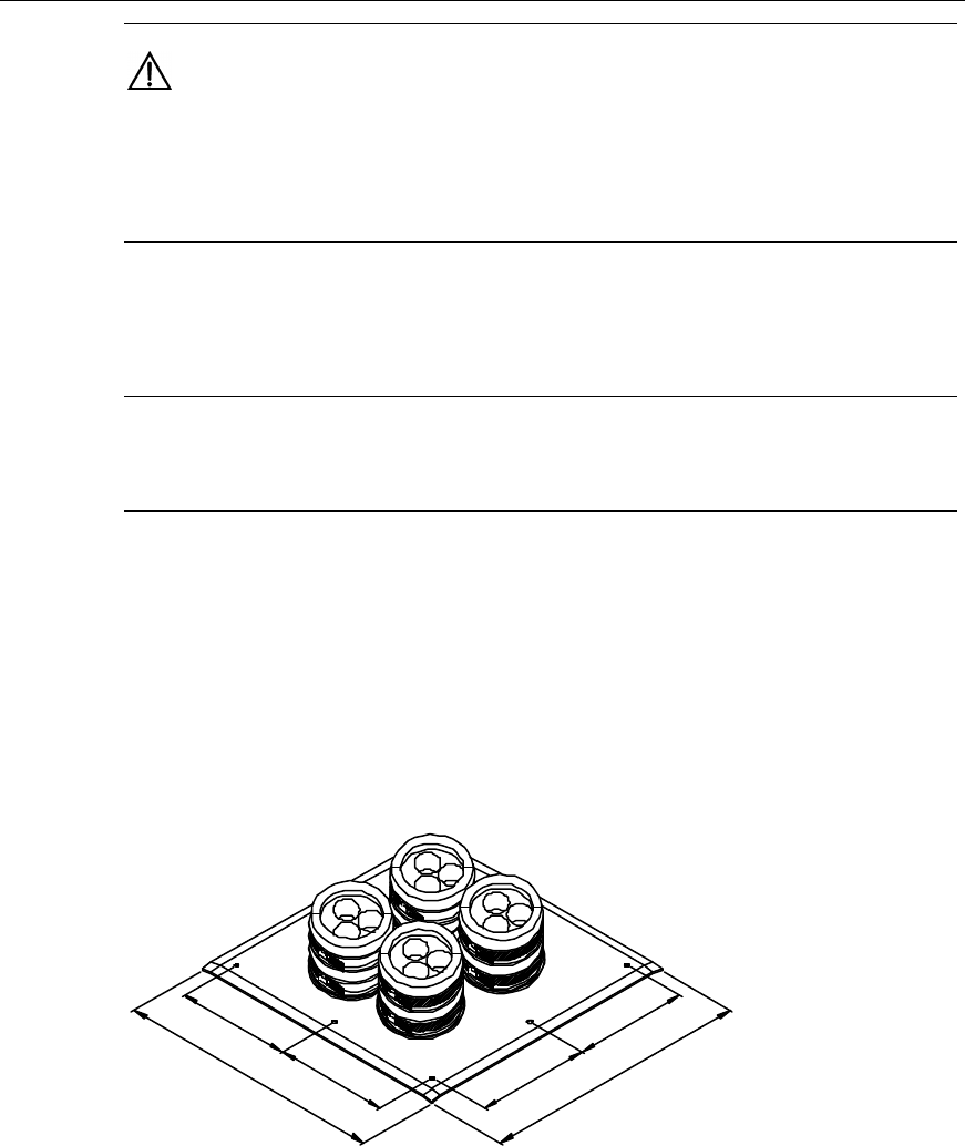
Installation Manual
Airbridge cBTS3612 CDMA Base Station Hardware Installation
6 Installing RF Antenna and Feeder System
6-44
Caution:
For each jumper, only one label is required, as the jumper is usually very short. The cable ties should
be wound in the same way. When cutting the cable ties, there should be an allowance of 5 ~ 10mm left
lest the cable ties fall off the jumper due to temperature change.
6.8 Installing Feeder Encapsulated Window
&
Note:
If there is no need to install the feeder encapsulated window on site, skip this section.
6.8.1 Structure
There are two types of feeder encapsulated windows. One is of the 12-hole type
and the other of the 27-hole type. The 12-hole feeder encapsulated window is used
most frequently. Figure 6-48 shows the size of it, and Figure 6-49 shows the
structure of it.
400
170 170
400
170
170
Figure 6-48 Size of the feeder encapsulated window (unit: mm)
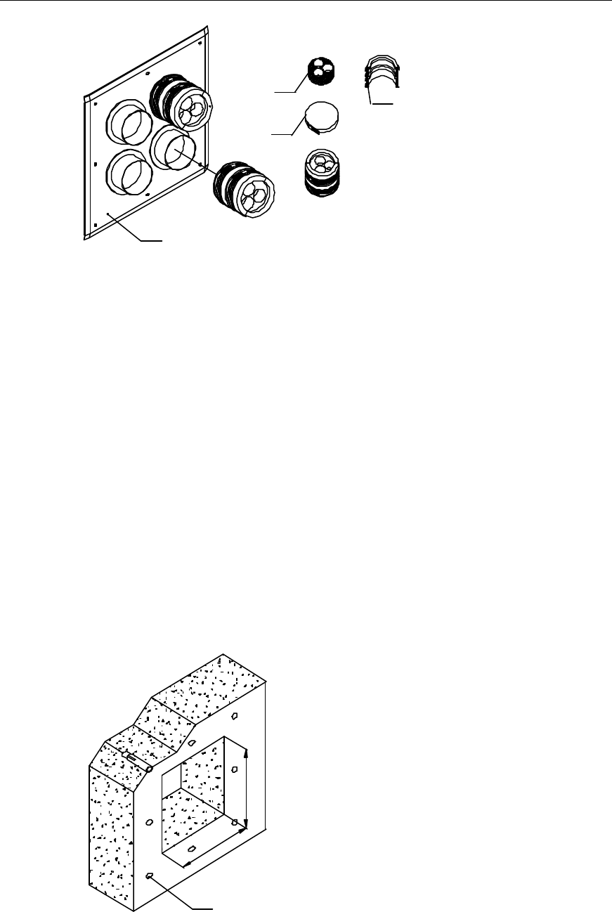
Installation Manual
Airbridge cBTS3612 CDMA Base Station Hardware Installation
6 Installing RF Antenna and Feeder System
6-45
(1)
(4)
(3)
(2)
(1) Encapsulating gasket (2) Sealing sleeve (3) Steel hoop (4) Window panel
Figure 6-49 Structure of the encapsulated window
6.8.2 Installing Encapsulated Window
The feeder encapsulated window is normally installed outdoors, near and above the
cabling rack. If feeders enter the equipment room through the roof, the encapsulated
window should be installed in the roof.
The installation procedures are as follows (12-hole feeder encapsulated window for
example):
1) Determine the installation location of the feeder encapsulated window in
accordance with the engineering design drawings as well as the size of the
window. Mark the hole sites for the expansion bolts and the position of the
window on the wall;
2) Make a 250mm%250mm opening in the wall and drill 8 holes for the expansion
bolts using a percussion drill, as shown in Figure 6-50;
250
250
Φ8
Figure 6-50 Mounting holes of the feeder encapsulated window (unit: mm)
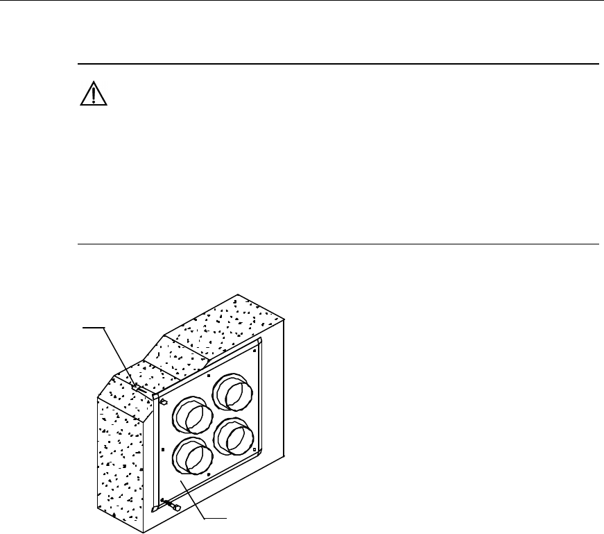
Installation Manual
Airbridge cBTS3612 CDMA Base Station Hardware Installation
6 Installing RF Antenna and Feeder System
6-46
3) Fix the plate of the feeder encapsulated window using expansion bolts as
shown in Figure 6-51;
Caution:
1) The spring washers and flat washers should be mounted for the expansion bolts, and the spring
washers should be above the flat washers;
2) Mount the sealing gasket and gland of the feeder encapsulated window when introducing feeders
into the equipment room;
3) Make sure the glue-adding holes in the sealing gland face upward.
(1)
(2)
(1) Expansion bolt M8%80 (2) Panel of the feeder encapsulated window
Figure 6-51 Installation of the feeder encapsulated window
6.9 Installing Feeders
The installation procedures of feeders are shown in Figure 6-52.
Installation Manual
Airbridge cBTS3612 CDMA Base Station Hardware Installation
6 Installing RF Antenna and Feeder System
6-47
Y
N
Connect the jumpers
between the antenna
and TTA
Start
Cut and label the feeders
Hoist and fix the feeders
Connect the jumpers
between the antenna and
the feeder
TTA included?
Distribute, fix and label
the feeders and install the
lightning protection clip
End
Lead the feeder into the
room
Install the lightening
arrester of the feeder(for
1900MHz band)
Install the indoor jumper
Figure 6-52 Installation procedures of the feeders
6.9.1 Cutting Feeders and Attaching Temporary Labels
The feeders can be cut prior to the hoisting. Alternatively, they can also be cut after
being hoisted and fixed in position. In the latter case, sufficient feeder should be left
for the cutting. The procedures of cutting are as follows:
1) Determine the length of the feeders required in each sector according to the
engineering design drawings;
2) Cut the feeder by the determined length, leaving an allowance of 1 ~ 2m. When
cutting the feeder, do not bend it and prevent it from being rolled over or
stepped on by vehicles or pedestrians;
Installation Manual
Airbridge cBTS3612 CDMA Base Station Hardware Installation
6 Installing RF Antenna and Feeder System
6-48
3) Attach the corresponding temporary label to both ends and in the middle of the
feeder after cutting each piece.
6.9.2 Hoisting and Fixing Feeders
1) Wrap the feeder end in a piece of gunny cloth (or antistatic bag) after the
corresponding connector is completed. Bind the cloth up using rope or binding
tape;
2) Knot the lifting rope round the feeder at the point 0.4m from the end and tie
another knot at the point 4.4m from the feeder end to prepare for the hoisting,
as shown in Figure 6-53. The person on the tower pull up the rope and the
person on the ground should keep pulling the rope to avoid any damage to the
antenna due to possible collision with the building or the tower;
4000
400
(1)
(3)
(2)
(4)
(5)
(1) Feeder connector (2) Wrapped connector (3) Lifting rope (4) Knot of the rope (5) Feeder
Figure 6-53 Protection of the feeder connector
3) Hoist the feeder onto the tower platform;
Caution:
Be careful during the hoisting. No violent hoisting is allowed so as to avoid damage to the feeder skin.
Installation Manual
Airbridge cBTS3612 CDMA Base Station Hardware Installation
6 Installing RF Antenna and Feeder System
6-49
4) Fix the upper end of the feeder in a proper position by multiple-point fastening
lest that the feeder falls from the tower. However, it should not be too close to
the antenna or TTA, as shown in Figure 6-54. Based on different fixing
requirements, select the 1-for-3 or 1-for-1 fixing clip, as shown in Figure 6-55.
Figure 6-54 Fixing the upper end of the feeder on the tower
2
(1) (2)
(2)
(1) 1-for-1 fixing clip (2) 1-for-3 fixing clip
Figure 6-55 Feeder fixing clips
6.9.3 Connecting Jumpers between Antenna and Feeder
The appearance of jumpers connected between the antenna and the feeder is
shown in Figure 6-56. Usually, the jumper is 3.5m long, as shown in Figure 6-57.
Installation Manual
Airbridge cBTS3612 CDMA Base Station Hardware Installation
6 Installing RF Antenna and Feeder System
6-50
(1) (2)
(3)
(4)
(1) Feeder (2) Metal label of the feeder (3) Encapsulated connector (4) Jumper
Figure 6-56 Jumper connected between the antenna and the feeder
&
Note:
The encapsulation treatment is usually carried out upon completion of the installation and the test of
the antenna & feeder system. It facilitates the replacing of the feeders and jumpers if there is any
problem in the antenna & feeder test. Figure 6-56 shows the connection of the jumper and the feeder
after the installation and the test of the whole antenna & feeder system.
(1) To the feeder (2) To the antenna
Figure 6-57 Jumper between the antenna and the feeder
Installation procedures are as follows:
1) Connect the jumper with the feeder. The jumpers should be bent in a natural
manner. The bending radius should be 20 times longer than the jumper
diameter.
2) Bind and distribute the jumpers.
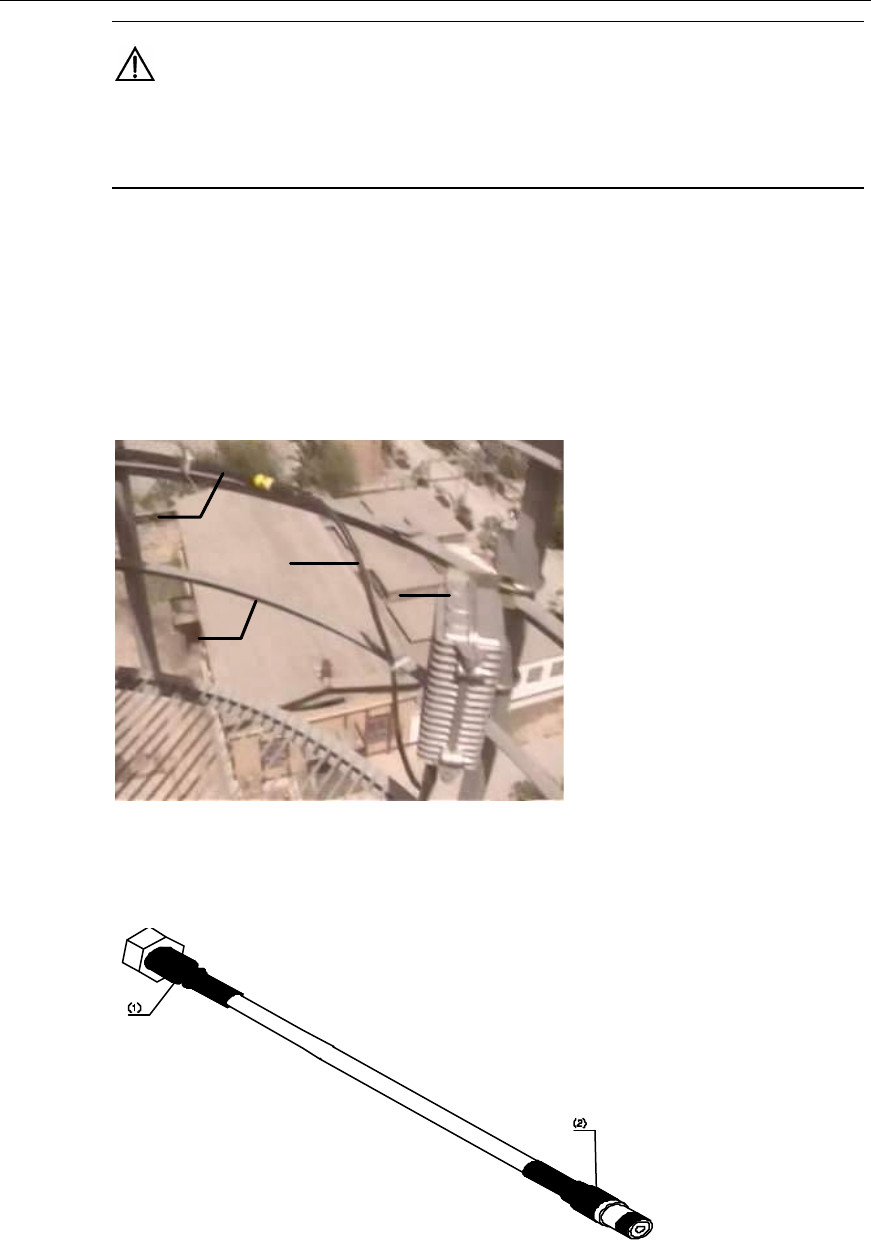
Installation Manual
Airbridge cBTS3612 CDMA Base Station Hardware Installation
6 Installing RF Antenna and Feeder System
6-51
Caution:
The binding tape should be wound in the same way. For the cuttings, there should be an allowance of
5 ~ 10mm left lest the tape should fall off the jumper due to temperature changes.
6.9.4 Connecting Jumpers between TTA and Feeder (if TTA Available)
When the TTA is available, the jumper should be installed between the TTA and the
feeder, as shown in Figure 6-58. Usually, the jumper is 1.5m long, as shown in
Figure 6-59
(1)
(2)
(3)
(4)
(1) Feeder (2) Tower guardrails (3) Jumper (4) TTA
Figure 6-58 Jumper connected between the TTA and the feeder
(1) To the TTA (2) To the feeder
Figure 6-59 Jumper between the TTA and the feeder
Installation Manual
Airbridge cBTS3612 CDMA Base Station Hardware Installation
6 Installing RF Antenna and Feeder System
6-52
Installation procedures are as follows:
1) Connect the jumper with the feeder. The jumpers should be bent in a natural
manner. The bending radius should be 20 times longer than the jumper
diameter.
2) Bind and distribute the jumpers.
Caution:
1) The binding tape should be wound in the same way. For the cuttings, there should be an allowance
of 5 ~ 10mm left lest the tape should fall off the jumper due to temperature changes.
2) The encapsulation treatment is usually carried out upon completion of the installation and the test of
the antenna & feeder system. It facilitates the replacing of the feeders and jumpers if there is any
problem in the antenna & feeder test.
6.9.5 Distributing and Fixing Feeders
I. Distribution principles
l The minimum bending radius of the feeders should be 20 times longer than the
feeder diameter;
l Feeders should not cross each other when running along the cabling rack or
down the tower. The feeders from the antenna to the place where they are
introduced into the equipment room should be distributed in good order;
l The distribution of feeders should be conducted from the top to the bottom, and
make sure to put the feeders in order and fix them with fixing clips while
distributing the feeders;
l The feeder fixing clips should be mounted every 2m or so along the tower or
the cabling rack. Based on the actual requirements, select the 1-for-3 or 1-for-2
or 1-for-1 fixing clip, as shown in Figure 6-60 and Figure 6-61 , Distributing the
feeder from the tower top to the encapsulated window is shown in Figure 6-62.
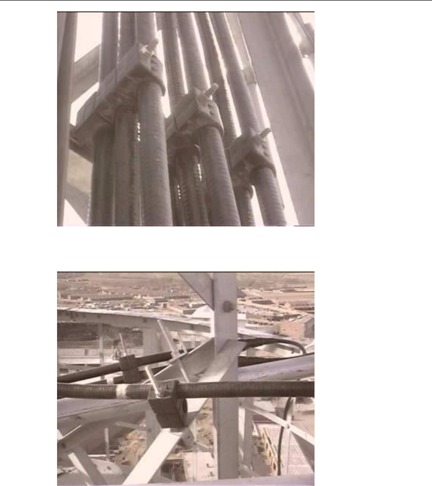
Installation Manual
Airbridge cBTS3612 CDMA Base Station Hardware Installation
6 Installing RF Antenna and Feeder System
6-53
Figure 6-60 Fixing the feeders on the tower (using the 1-for-3 fixing clip)
Figure 6-61 Fixing the feeders on the tower (using the 1-for-2 fixing clip)
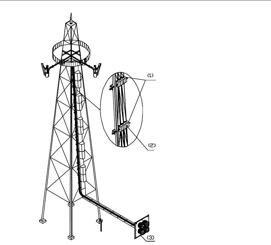
Installation Manual
Airbridge cBTS3612 CDMA Base Station Hardware Installation
6 Installing RF Antenna and Feeder System
6-54
(1) Spacing between the feeder fixing clips (2) Feeder fixing clip (3) Feeder encapsulated window
Figure 6-62 Distributing the feeder from the tower top to the encapsulated window
l Feeder fixing clips should be spaced regularly and oriented in the same
direction;
l When distributing the feeders at the roof, place the feeders in the
corresponding feeder fixing clips according to the names on the feeder labels.
Do not fasten them until they are all distributed neatly. The fixing clips should
be strictly perpendicular to the feeders. Feeders in the same clip should be
parallel to each other, as shown in Figure 6-63.
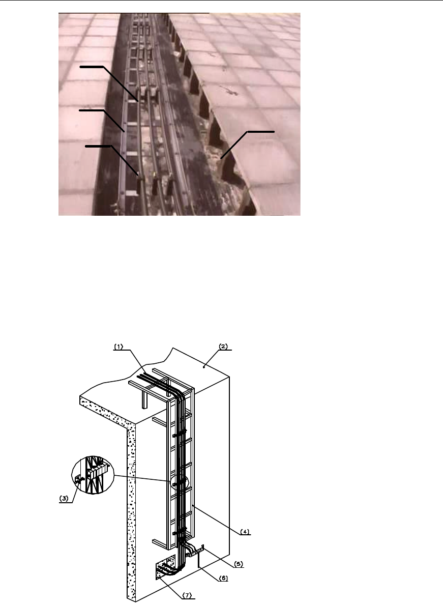
Installation Manual
Airbridge cBTS3612 CDMA Base Station Hardware Installation
6 Installing RF Antenna and Feeder System
6-55
(1)
(2)
(3) (4)
(1) Feeder (2) Cabling rack (3) Feeder fixing clip (4) Feeder well at the roof
Figure 6-63 Feeders in the fixing clips
l When the feeders from the roof enter the equipment room along the wall,
cabling ladder is required if the cabling distance is longer than 1m. The feeders
should be fixed to the cabling ladder using the fixing clips, as shown in
Figure 6-64.
(1) Feeder (2) Roof (3) Feeder fixing clip
(4) Outdoor cabling rack (5)Outdoor grounding strip (6) To the outdoor lightning
protection grounding cables
(7) Feeder encapsulated window
Figure 6-64 Distributing the feeder from the roof to the feeder encapsulated window
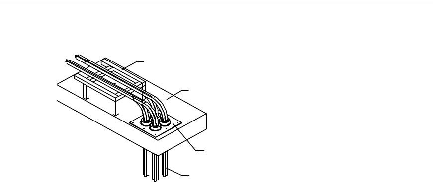
Installation Manual
Airbridge cBTS3612 CDMA Base Station Hardware Installation
6 Installing RF Antenna and Feeder System
6-56
l If feeders enter the equipment room through the feeder encapsulated window
in the roof, keep the window strictly encapsulated, as shown in Figure 6-65.
(1)
(2)
(3)
(4)
(1) Cabling rack at the roof (2) Roof (3) Feeder encapsulated window (4)Feeder
Figure 6-65 Introducing the feeder into the equipment room through the roof
II. Distributing and fixing se quence
1) Design the feeder arrangement based on the sector requirements in the
engineering design, and determine the plan on the feeder arrangement and
lead-in. Normally the feeders in one sector are arranged in one column or row.
The arrangement sequences of the feeders in each column and row should be
consistent with each other.
2) Arrange the feeders according to the designed sequence;
3) Fix the feeders onto the tower or the cabling rack while arranging them neatly.
Meanwhile, mount the feeder grounding clips and replace the temporary labels
with formal metal labels.
III. Connector processing principles
l If a connector is not completely made in one day or if a completed connector is
not applied for the connection of the jumper and feeder soon, the connector
should go through simple waterproof treatment.
l If the installation of the antenna & feeder system can’t be completed in one day,
the outdoor connectors or exposed ends of feeders should go through simple
waterproof treatment. All the outdoor connectors should go through the
waterproof and capsulation treatment after the installation and the test of the
antenna & feeder system.
6.9.6 Feeder engineering labels
I. Label format
Both indoor and outdoor labels are made of aluminum. The labels are illustrated in
Figure 6-66.
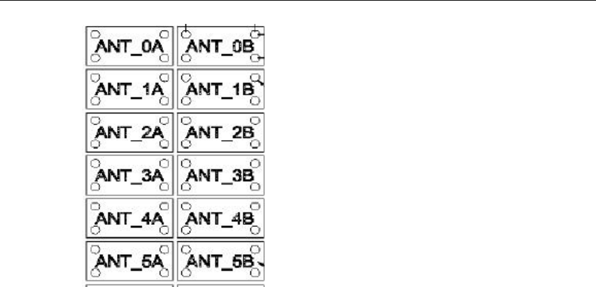
Installation Manual
Airbridge cBTS3612 CDMA Base Station Hardware Installation
6 Installing RF Antenna and Feeder System
6-57
Figure 6-66 Label appearance
II. Label specifications
The labels of antenna and feeder are usually attached at the following three places:
l The places 200mm away from the outdoor feeder connectors;
l The places 200mm away from the outside of the feeder encapsulated window;
l The joints between the indoor feeders and the jumpers.
6.9.7 Grounding Feeders
I. Installation locations of feeder grounding clips
The feeder grounding clips should be installed simultaneously with the feeder
distribution.
The feeders should be grounded for lightning protection at the following points when
antennas are installed on the tower:
l About 1m behind the place where the main feeder is led from the tower
platform.
l About 1m in front of the place where the main feeder is led from the tower body
to the outdoor cabling rack.
l At the outer side of the feeder window before which the main feeder is led into.
See Figure 6-67.
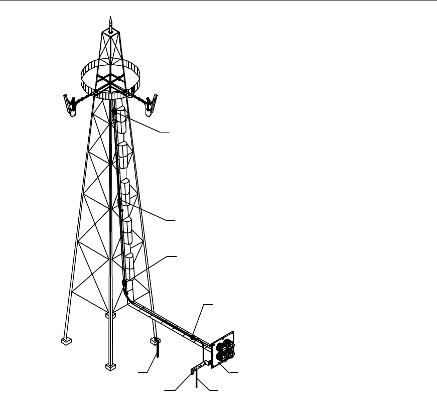
Installation Manual
Airbridge cBTS3612 CDMA Base Station Hardware Installation
6 Installing RF Antenna and Feeder System
6-58
(1)
(2)
(3)
(4)
(5)
(6)
(7)
(8)
(1) Grounding at the top of the
feeder (2) Grounding in the middle of the
feeder (when over 60m) (3) Grounding at the bottom of the
feeder
(4) Grounding at the place where
the feeder is to enter the
equipment room
(5) Feeder encapsulated window (6) To the outdoor lightning
protection grounding cables
(7) Outdoor grounding copper bar (8) Tower grounding bar
Figure 6-67 Lightning protection grounding of the feeder (installing the antenna on the tower)
The feeders should be grounded for lightning protection at the following points when
antennas are installed on the roof:
l Within 1m from the feeder connector;
l At the places where the feeders are led down from the roof;
l On the feeder outside the feeder encapsulated window (as close to the window
as possible).
See Figure 6-68.
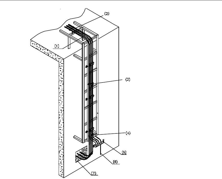
Installation Manual
Airbridge cBTS3612 CDMA Base Station Hardware Installation
6 Installing RF Antenna and Feeder System
6-59
(1) Feeder (2) Grounding at the top of the
feeder (3) Grounding in the middle of the
feeder (when over 60m)
(4) Grounding at the place where
the feeder is to enter into the
equipment room (5) Outdoor grounding bar (6) Outdoor lightning protection
grounding cable
(7) Feeder encapsulated window
Figure 6-68 Lightning protection grounding of the feeder down the cabling ladder
For others, the feeder grounding points lie:
l When the length of a feeder is more than 60m, the feeder grounding clips
should be applied along the feeder. Usually, the grounding clips should be
mounted every 20m.
l If the feeder should be distributed at the roof prior to entering the equipment
room and the length to be distributed at the roof exceeds 20m, a feeder
grounding clip should be applied at the roof.
II. Feeder grounding clip installation
For the installation of the feeder grounding clips, please refer to Appendix G.
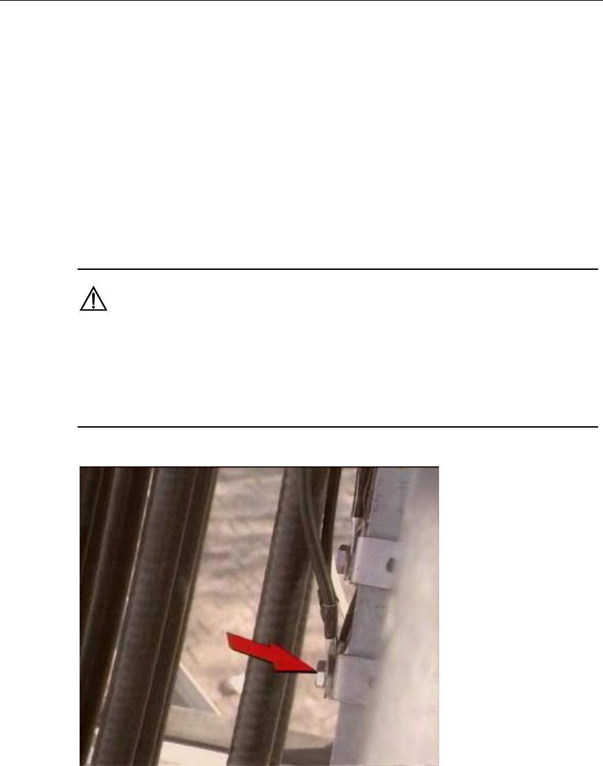
Installation Manual
Airbridge cBTS3612 CDMA Base Station Hardware Installation
6 Installing RF Antenna and Feeder System
6-60
III. Items for attention
1) Connect the grounding cable of the grounding clip to the grounding part of the
cabling rack securely. When distributing the feeders along the tower, if there
are grounding point for the grounding clips on the tower body, connect the
grounding cable of the grounding clip directly to the steel plate of the tower, as
shown in Figure 6-69. If there is no grounding point on the tower body, use the
base of the feeder fixing clip to connect the grounding cables. In this case, fix
the base onto the tower or the outdoor cabling rack and then connect the
grounding cable to the base. When the feeders are distributed on the outdoor
cabling rack, the grounding cables can be connected to the well-grounded
cabling rack;
Caution:
The anti-rusting paint around the grounding part of the cabling rack should be removed prior to the
connection and a new coat of anti-rusting paint should be applied after the connection around the lug,
nut and cabling racks. Besides, the bare wire and the lug handle should be wrapped with insulating
tape.
Figure 6-69 Connecting the grounding cable of the feeder grounding clip to the steel plate of the tower
2) The grounding cable of the feeder grounding clips on the outdoor feeders
should be neatly led to the outdoor grounding bar, as shown in Figure 6-70. If
no outdoor grounding bar is available, they can be connected to the well-
grounded outdoor cabling rack or to the lightning protection grounding net of
the building, as shown in Figure 6-71.
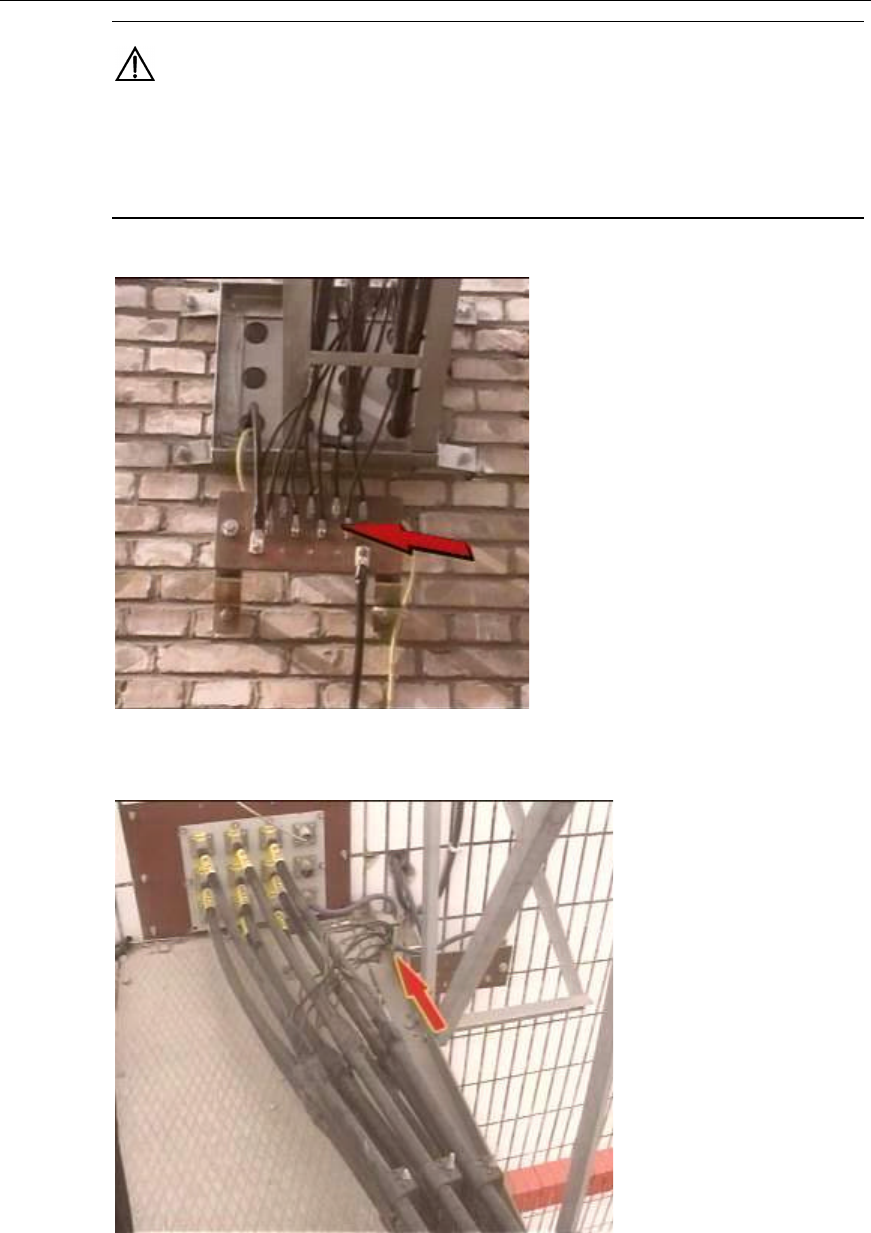
Installation Manual
Airbridge cBTS3612 CDMA Base Station Hardware Installation
6 Installing RF Antenna and Feeder System
6-61
Caution:
The grounding cable and the grounding connector should go through the antirust treatment. The lug,
nut and cabling racks should be coated with anti-rusting paint. The bare wire and the lug handle should
be wrapped with insulating tape.
Figure 6-70 Grounding when the feeder does not enter the equipment room (grounding bar available)
Figure 6-71 Grounding when the feeder does not enter the equipment room (grounding bar
unavailable)

Installation Manual
Airbridge cBTS3612 CDMA Base Station Hardware Installation
6 Installing RF Antenna and Feeder System
6-62
6.9.8 Leading Feeder into Equipment Room
Generally, the feeder encapsulated window installed in the equipment room is of the
12-hole type. Therefore, this section only describes how to lead the feeders into the
equipment room through the 12-hole encapsulated window. As for the 27-holes
encapsulated window, take this section for reference.
I. Arrangement principles
l There are 4 large openings in a 12-hole encapsulated window. And each
opening is divided into 3 holes, each for one feeder;
l The feeders should be laid out clockwise or counter clockwise according to
their numbers in the three small holes of the same opening;
l The layout of the feeders should facilitate expansion, since the layout in the
feeder window is not allowed to be changed during system expansion, instead,
it is only possible to add feeders in the feeder window or to change the jumper
connection on the set-top;
l The feeder layout in the feeder window should facilitate the layout on the
cabling rack and the connection on the set top. The feeders should be in
parallel without intertwining.
II. Procedures
1) Lead each feeder into the equipment room through the feeder encapsulated
window. During the operation, some personnel should provide cooperation in
the room lest the feeders damage the indoor equipment;
2) Make the waterproof curve of the feeders outside the encapsulated window;
3) Mount the sealing gasket and sleeve for the feeder encapsulated window.
Make sure the glue-adding holes in the sealing sleeve face upward;
4) Cut feeders to accurate length according to the installation location of the
lightning arrester determined by the design requirements;
5) Make the indoor feeder connectors;
Caution:
When the feeder encapsulated window and the indoor cabling racks are not of the same height, bend
the feeders in a natural manner, and the minimum bending radius of the feeder should be 20 times of
the feeder diameter or longer.
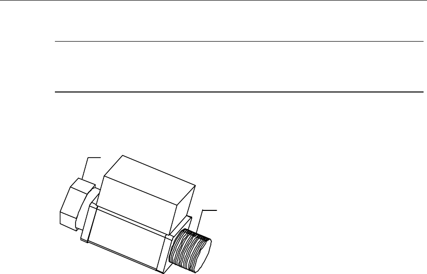
Installation Manual
Airbridge cBTS3612 CDMA Base Station Hardware Installation
6 Installing RF Antenna and Feeder System
6-63
6.9.9 Installing Lightning Arrester for Feeders
&
Note:
This section only applies to band 1900MHz.
The outline of the lightning arrester is shown in Figure 6-72.
(1)
(2)
(1) Lightening protection end (2) Equipment end
Figure 6-72 Lightning arrester for TX and RX
As the feeders are required to be cut off at the point 800mm ~ 1500mm away from
the place where they enter the room, the lightning arrester can be located. Install it
by the engineering design drawings.
All lightning arresters should be oriented in the same direction and securely
connected. The lightening protection end of the lightning arresters should be
connected to the feeder and the equipment end to the set-top jumper.
Installation procedures are as follows:
1) Check if the type of the lightning arrester is fit for its application and orient it in
the right direction.
2) After leading the feeders into the equipment room and making the connectors,
connect the feeders with the lightening protection ends of the lightening
arresters. The lightning end as well as the equipment end should be marked on
the lightning arresters.
3) Connect the lightning arrester with a grounding cable, and then connect the
cable to the grounding bar especially for the lightning arrester, as shown in
Figure 6-73. The radius of the grounding cable should be no less than 6mm2.
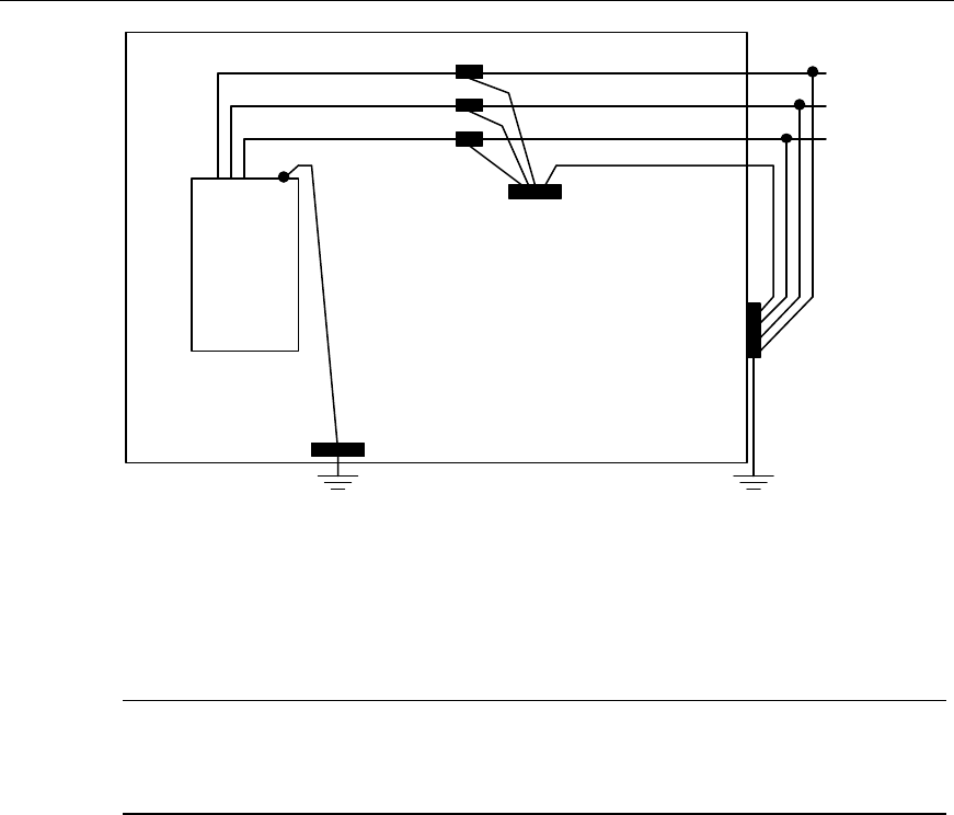
Installation Manual
Airbridge cBTS3612 CDMA Base Station Hardware Installation
6 Installing RF Antenna and Feeder System
6-64
Grounding Bar
for Lightening
Arrester
Protection Grounding Bar
in Equipment Room
Lightening Arrester
cBTS3612
Protection
Grounding
Cable
Feeder
Outdoor
Grounding
Bar
Equipment
Room
Feeder
Feeder
Grounding Cables
Grounding
Cables
Figure 6-73 Grounding the lightning arrester
4) Connect the grounding bar for the lightning arrester with a grounding cable, and
then connect the cable to the outdoor grounding bar, as shown in Figure 6-73.
The radius of the grounding cable should be no less than 16mm2.
&
Note:
The grounding bar for the lightning arrester can be installed on the wall and the cabling rack.
6.9.10 Installing Indoor Jumpers
The connectors of the indoor jumpers (1/2”) are usually made on the site.
I. Installing jumpers on cabinet top
1) Cut the jumpers to a proper length according to the actual distribution route;
2) Make the connectors (7/16DIN male) to be used at the cabinet top following the
instruction delivered with the components;
3) Connect one end of the jumper to the corresponding connector of the antenna
& feeder jumper at the cabinet top, and another end to the corresponding
feeder (For band 1900MHz, another end to the equipment end of the
corresponding lightning arrester).
The detailed connection of the jumpers and the set-top connectors is described as
follows:
The silkscreen of the jumper outlet at the cabinet-top is shown in Figure 6-74.
Installation Manual
Airbridge cBTS3612 CDMA Base Station Hardware Installation
6 Installing RF Antenna and Feeder System
6-65
ANT_0A
ANT_0B
ANT_1A
ANT_1B
ANT_2A
ANT_2B
ANT_5A
ANT_5B
ANT_4A
ANT_4B
ANT_3A
ANT_3B
Figure 6-74 Silk-screen of jumper outlet at the cabinet top
The relationship between the port allocation and the sector are as follows:
l For omnidirectional BTS:
Omnidirectional BTS Occupied jumper outlets at the cabinet-top
ANT-0A
One sector ANT-0B
l For three-sector BTS:
Three-sector BTS Occupied jumper outlets at the cabinet-top
ANT-0A
Sector 1 ANT-0B
ANT-2A
Sector 2 ANT-2B
ANT-4A
Sector 3 ANT-4B
l For six-sector BTS:
Six-sector BTS Occupied jumper outlets at the cabinet-top
ANT-0A
Sector 1 ANT-0B
ANT-1A
Sector 2 ANT-1B
ANT-2A
Sector 3 ANT-2B
ANT-3A
Sector 4 ANT-3B
ANT-4A
Sector 5 ANT-4B
Installation Manual
Airbridge cBTS3612 CDMA Base Station Hardware Installation
6 Installing RF Antenna and Feeder System
6-66
Six-sector BTS Occupied jumper outlets at the cabinet-top
ANT-5A
Sector 6 ANT-5B
&
Note:
1) If transmit diversity is not adopted, A is used for diversity receiving and transmi tting, while B is for
diversity receiving.
2) If transmit diversity is adopt, A is used for main receiving and transmitting, while B is for diversity
receiving and transmitting.
II. Jumper distribution and binding requirements
l The jumpers between the cabinet top and the cabling rack should be distributed
in parallel;
l When the jumpers are required to go through the cabling rack to the upper part
of the cabling rack, they should not be distributed outside the rack;
l Bend the jumpers in a natural manner with the bending radius 20 times longer
than the jumper diameter;
l The jumpers between the cabinet top and the cabling rack should be tensed to
a proper tightness;
l The jumpers through the cabling rack should be distributed in parallel;
l The jumpers should be bound onto all crossbars of the cabling rack. The cable
ties should be oriented in the same direction and be cut smoothly.
6.10 Testing Antenna & Feeder System
Measure the antenna & feeder VSWR on the jumpers at cabinet top using the Site
Master. Normally, the antenna VSWR should be less than 1.5 (including when there
is TTA in the system). However, the VSWR of the N-type male connector on the
jumper (1/4”) between the antenna & feeder system and the duplexer output port
should be less than 1.3. (The corresponding return loss is 18dB.)
If the VSWR is greater than 1.5, it indicates there are problems in the antenna &
feeder system. In this case, measure the VSWR hop by hop or the return loss of the
entire system to locate the problem.

Installation Manual
Airbridge cBTS3612 CDMA Base Station Hardware Installation
6 Installing RF Antenna and Feeder System
6-67
6.11 Waterproof & Encapsulation Treatment for Connectors
and Feeder Encapsulated Window
The waterproof and encapsulation treatment should be applied to the outdoor
connectors and the feeder encapsulated window immediately after the installation
and the test of the antenna & feeder system. The outdoor connectors are those
between jumper and TTA and those between jumper and feeder.
6.11.1 For Outdoor Connectors
Wrap up the connector first using semi-conductive self-adhesive tape, then using
waterproof tape and finally using electric insulation tape. Each tape should be
wound into three layers: from the bottom to the top at the first layer, from the top to
the bottom at the second, and then from the bottom to the top at the third. The upper
layer of the tape should overlap one-third width of the under layer. The tape should
be tensed to a proper degree during each winding. All these should satisfy the
waterproof and encapsulation requirements.
&
Note:
When capsulate the connector, wind the electric insulation tape for the first layer and then the semi-
conductive self-adhesive tape, to facilitate the dismantling of the tape.
6.11.2 For Feeder Encapsulated Window
1) Put the two semicircle sealing sleeves around the outside of the big holes in the
feeder encapsulated window;
2) Put the two steel hoop in the two grooves of the sealing sleeves, screw down
the screws on the hoop using screwdriver;
3) Inject the glass cement to the gap around the feeder encapsulated window;
4) Plug the holes unused with special stoppers.
The feeder encapsulated window applied with waterproof & encapsulation treatment
is shown in Figure 6-75.
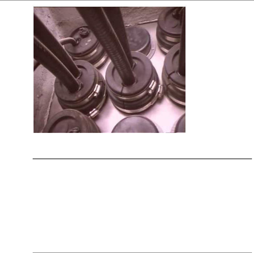
Installation Manual
Airbridge cBTS3612 CDMA Base Station Hardware Installation
6 Installing RF Antenna and Feeder System
6-68
Figure 6-75 Feeder encapsulated window applied with waterproof & encapsulation treatment
&
Note:
If the feeder enters the equipment room through a glass window, the treating methods and procedures
are as follows:
1) Remove the glass, and cut an opening of the proper size round the corner of the glass;
2) Protect the cutting position using the rubber or adhesive tape. Wrap the feeder to be led through the
opening with the adhesive tape lest that the opening edge scratch the feeder;
3) Lead in the feeder through the glass window;
4) Make the waterproof & encapsulation treatment by sealing the interface between the feeder and the
glass using the glass cement.

Installation Manual
Airbridge cBTS3612 CDMA Base Station Hardware Installation
7 Installing Satellite Synchronization Antenna and Feeder System
7-1
7 Installing Satellite Synchronization Antenna and
Feeder System
7.1 Overview
This chapter aims to introduce the installation of satellite synchronization antenna
and feeder system taking GPS as an example. In practical installation, it can be
performed in step with that of RF antenna and feeder system.
Regarding the same contents with the installation of RF antenna and feeder system,
this chapter will cover only the differences between the two-system installation.
7.1.1 Installing GPS Antenna and Feeder System
Generally speaking, the installation of GPS antenna and feeder system is basically
the same with that of RF antenna and feeder system. The major differences lie
between the GPS antenna and RF antenna. In addition, GPS antenna and feeder
installation includes the installation of indoor/outdoor lightning arrester. The specific
process is as follows:
1) Check the installation environment of GPS antenna and feeder system.
2) Get familiar with the engineering design documents and determine the
installation scheme.
3) Install antenna support.
4) Install antenna
5) Connect outdoor jumpers
6) Install lightning arrester on the antenna side
7) Prepare the connectors of feeders, route the outdoor feeders and attach the
labels on them.
8) Install grounding clips for feeders.
9) Install equipment-side lightning arrester
10) Inspect the project installation.
&
Note:
The installation of GPS antenna and feeder system can be performed simultaneously with that of RF
antenna and feeder system. The specific installation process can be adjusted according to the actual
configuration and environment.
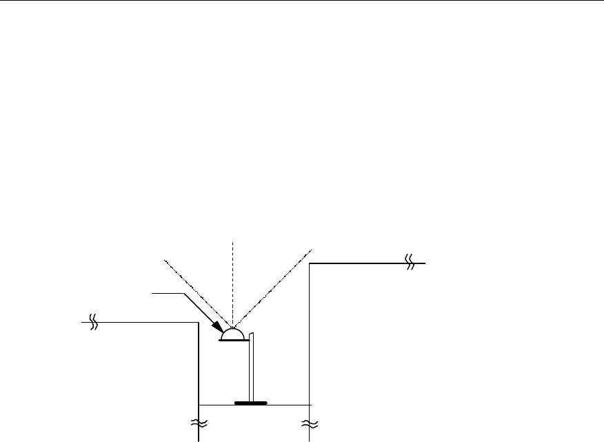
Installation Manual
Airbridge cBTS3612 CDMA Base Station Hardware Installation
7 Installing Satellite Synchronization Antenna and Feeder System
7-2
7.2 Installing Antenna
7.2.1 Requirements for Installation Position
The installation position for GPS/GLONASS antenna should have a broadening
vision with no high buildings around, and as far as possible from the compact
accessory buildings on the building-top. The available area of the plane for installing
GPS/GLONASS should be as big as possible. And the antenna should be vertically
erected with a visual angle of more than 90°.
(2)
(1) (1)
≥ 90°
(1) Surrounding buildings or other obstacles (2) GPS/GLONASS antenna
Figure 7-1 Antenna installation position
l Note that the antenna should not be close-range radiated by the front face of
the main lobe of the mobile communication antenna. In addition, it should not
locate at the range of the microwave signal from microwave antenna, not below
the high voltage cable and not under the intense radiation of TV launching
tower.
l Considering lightning protection, the antenna should be installed at the center
of the building-top as possible as it can be. Try not to install it on the stub wall
around the building-top. Do not install the antenna at the corner of the
building-top as the corner has a greatest possibility of being stricken by
lightning.
l The antenna should be installed at the place where there is special lightning
rod or similar facilities such as the tower for telecommunication around. And the
antenna should locate within the valid protection range of the lightning rod. That
is, the included angle between the erect direction and the cable that connects
the receiving connector of the antenna to the lightning rod or tower-top should
be less than 30°. If there is no tower or lightning rod around, the special
lightning rod should be installed to meet the design requirements for lightning
protection. The horizontal distance from the lightning rod to the antenna should

Installation Manual
Airbridge cBTS3612 CDMA Base Station Hardware Installation
7 Installing Satellite Synchronization Antenna and Feeder System
7-3
fall within 2~3m preferably. And the height of the lightning rod should be more
than 0.5m higher than that of GPS antenna receiving connector.
7.2.2 Preparation for Installation Position of Antenna
I. Processing cement base
The cement base can be used to fix the antenna bracket. Diameter of the metal
base for the antenna bracket is 300mm and the diameter of its installation hole is
11mm.
It is recommended that the dimensions of the cement base should meet: 500mm
(length) × 500mm (width) × 200mm (height). Cement base should be made of
concrete and reinforcing steel bars. And make sure that there is adequate intensity
for installing expansion bolts. The upper surface of the cement base should be kept
as horizontal as possible to guarantee that the antenna pole is upward erectly.
With the permission of user, and the reliable waterproof capability of the building-top,
the ground for installation should be roughened to ensure the effective joint between
the cement base and the plane of the installation position, so as to increase the
intensity of reinforcement.
Note the influence from the outdoor temperature when making the base, especially
in the cold areas. In the cold areas, make the cement base at the installation
position beforehand, to avoid the inability of civil work due to the extreme low
temperature, even to influence the trouble-free operation.
II. Requirements for stub wall
Besides cement base, the stub wall around the building-top can also be used to fix
the antenna. The position of the wall and environment around should meet the
requirements in “7.2.1 Requirements for Installation Position“.
Considering the nicety of the building-top of the user after the installation, it is
preferable to choose those places that are easily to be neglected.
Stub wall should be intense and high enough for being drilled and installed with
expansion screws.
III. Requirements for installing antenna on tower
When installing GPS/GLONASS antenna on the tower, generally, the antenna is
installed at the bottom of the tower. The antenna should be as far as possible from
the high power antenna on the tower-top, and be fixed using antenna support to
avoid the influence from the tower body. It is also recommended that the antenna
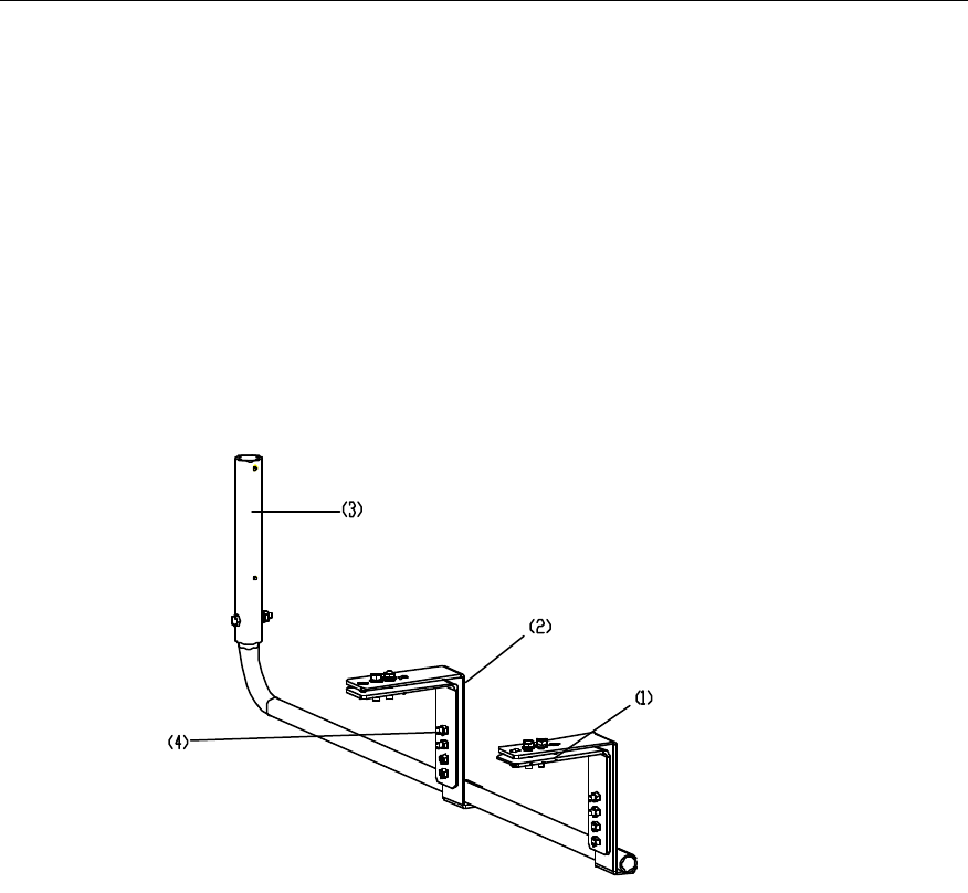
Installation Manual
Airbridge cBTS3612 CDMA Base Station Hardware Installation
7 Installing Satellite Synchronization Antenna and Feeder System
7-4
should have no other barrier around itself lest the receiving performance should be
lessened.
7.2.3 Installing Antenna Bracket
Antenna brackets of different forms are available for different installation modes.
I. Installation on tower
Figure 7-2 illustrates the antenna supports installed on tower.
(1) Adjustable clamp (2) Fixed clamp (3) Support (4) M8 bolts
Figure 7-2 Antenna support on tower
Installation steps:
1) Unscrew the bolts on the fixed clamps and take down the adjustable clamps;
2) Set the antenna support in the right position on the tower so that the tower
angle iron is between the fixed clamp and the adjustable clamp;
3) Fix the support on the tower with fasteners including bolts, flat washers, spring
washers and nuts:
4) Insert the antenna rod into the support and put it through the bolt hole. Tighten
the bolts to fix the antenna support.
Figure 7-3 illustrates an installed antenna support on the tower.
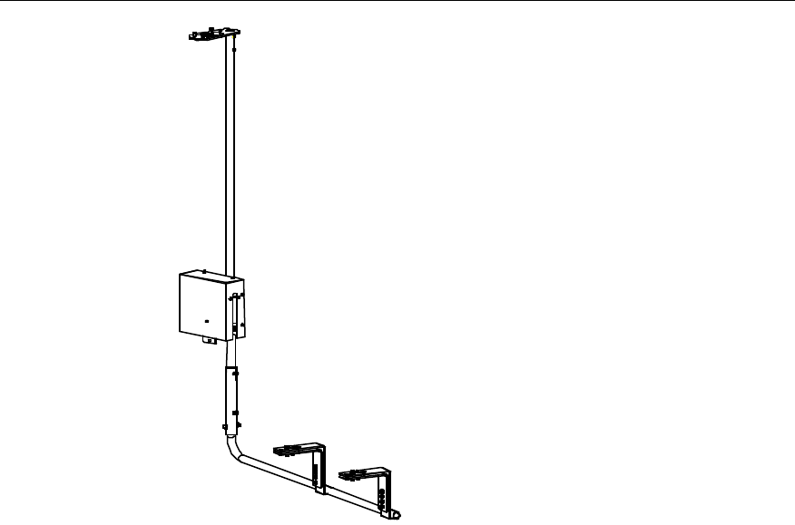
Installation Manual
Airbridge cBTS3612 CDMA Base Station Hardware Installation
7 Installing Satellite Synchronization Antenna and Feeder System
7-5
Figure 7-3 Installed antenna support on tower
II. Installation on roof
Figure 7-4 illustrates the antenna support installed on building roof.
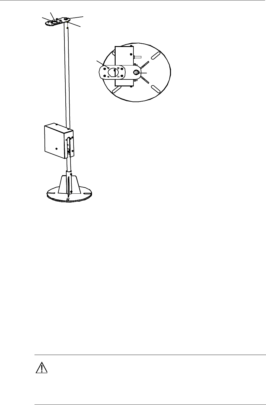
Installation Manual
Airbridge cBTS3612 CDMA Base Station Hardware Installation
7 Installing Satellite Synchronization Antenna and Feeder System
7-6
M1
M2 (4 bolt holes)
M3
B1 (2 bolts)
M2
M1
M3
M1
M2 (4 bolt holes)
M3
B1 (2 bolts)
M2
M1
M3
Figure 7-4 Structure of GPS antenna support
III. Cement base
l Place the metal base of the antenna support on the cement base, align the
centers of the two bases and record the position for installation hole with a
project pen.
l Drill holes according to the marks using the drill bit with the diameter of v12.
l Install expansion bolts to fasten the base. In order to keep the antenna pole
erected vertically, further to reach the well receiving performance, try to keep
the metal base leveled with the amending of washers.
l Insert the support lever into the base to see whether the lever is erected
vertically. It is required that the included angle between the support lever and
the direction of the plummet should be smaller than 5°. If it can not be reached,
adjust the base.
Caution:
In order to ensure that the project is completed as scheduled, it is required that the cement base be
done before the equipment installation.
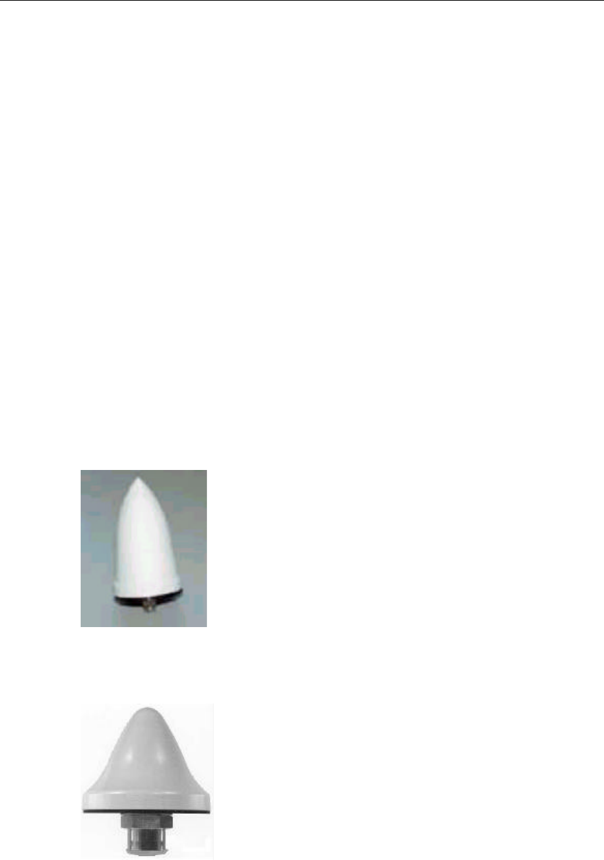
Installation Manual
Airbridge cBTS3612 CDMA Base Station Hardware Installation
7 Installing Satellite Synchronization Antenna and Feeder System
7-7
IV. Stub wall
l Stand the antenna pole, with the end where antenna receiving connector is
located, upward, make the pole leaned along the wall vertically, and mark the
position where the hole is to be drilled with a project pen. In order to ensure the
stability and reliability, two fixing hoops should be used. And the distance
between the two hoops should not be less than 40cm, and their positions on
the wall should be kept evenly and symmetrically from the upper to the lower.
l Drill holes at the place where marks exist. Since the specification of the
expansion bolt is M10, the v12 drill bit may be adopted. Add rubber washer to
increase the stability when using fixing hoop to fasten the antenna pole.
l After the installation, the pole should not get loosed when being pulled and
rotated the pole by hand. Check whether the antenna is erected vertically, and
the included angle between the support lever and the direction of the plummet
is less than 5°.
7.2.4 Installing Antenna
There are various types of antennas. Figure 7-5 and Figure 7-6 shows the common
used antennae. Here we will provide you with the installation of two GPS antennae
respectively.
Figure 7-5 GPS antenna of Type AT1670-0
Figure 7-6 GPS antenna of Type UNONCORE
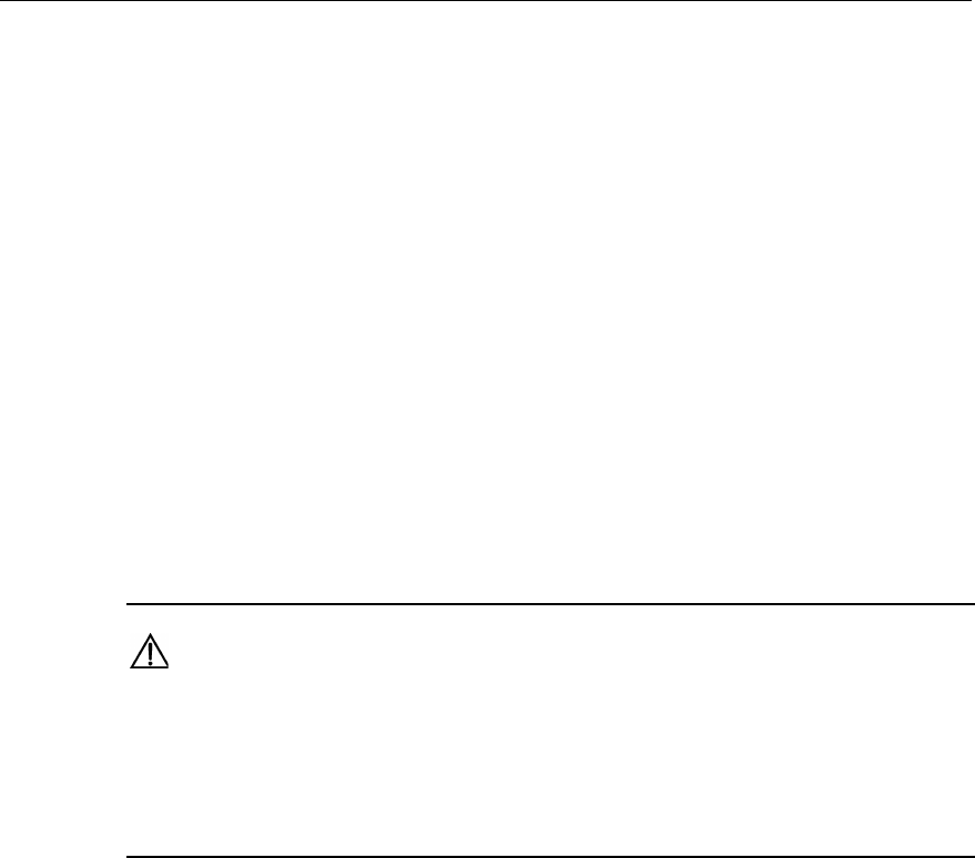
Installation Manual
Airbridge cBTS3612 CDMA Base Station Hardware Installation
7 Installing Satellite Synchronization Antenna and Feeder System
7-8
I. Installing GPS antenna of Type AT1670-0
1) Insert the jumper connector at the antenna bottom into M3 of the bracket as
shown in Figure 7-4;
2) Then fasten the four accessory UK-standard bolts at M2;
3) Finally tighten the antenna connector and the cable socket.
II. Installing GPS antenna of Type UNONCORE
1) UNONCORE GPS antenna has such auxiliary fixtures as a rubber washer, a
metal flat washer and a bolt. Upon installation, first unfix the bolt at the antenna
bottom and install the rubber washer instead. Then insert the antenna into M3
as shown in Figure 7-4;
2) Install the metal flat washer on the jumper connector at the bottom of the
antenna (with the washer head tightly against the bottom of the M3);
3) Tighten the antenna connector and the cable socket. Finally reinstall the
unfixed bolt. Thus the GPS antenna is fixed on the ellipse holder of the antenna
support.
Caution:
1) Joints of the antenna should be handled with waterproof and sealing measures. Winding principle of
tapes is available in the section “8.3.2 Jumper Connection of the Antenna”.
2) After the installation, cover the antenna support with rustproof paint, especially the fixing bolts,
expansion bolts and the places around the bolt holes.
7.3 Installing Feeders
Feeder installation involves the installation of jumpers, lightning arrester on the
antenna side, feeder, lightning arrester on the equipment side, and so on. The
installation sequence is antenna, 1.5m jumper, lightning arrester on the antenna
side, feeder, lightning protection grounding clip, and lightning arrester on the
equipment side. The whole installation procedures should be conducted from the top
downward step by step.
7.3.1 Routing Feeders
Prior to feeder routing, carefully check the routing environment including the tower
and roof, etc. Determine the routing scheme and sequence as per the engineer
drawing.
l The route leading the feeder from the installation hole to the equipment room
where cabinet equipment is located should be clear and can be fixed easily and

Installation Manual
Airbridge cBTS3612 CDMA Base Station Hardware Installation
7 Installing Satellite Synchronization Antenna and Feeder System
7-9
properly, meeting the cabling requirements in the equipment room. And reliable
rainproof and anticorrosive measures are available.
l 1.5m jumper should be bound at the outside of the antenna support lever
evenly using cable ties. In addition all cable ties should be fastened, with a
same spacing of 200mm. The direction of the cable tie heads should be
consistent, and all the ties should be cut fully to keep the jumper surface
smooth.
l Waterproof curve should be installed at the entrance from outdoors to indoors.
The vertical distance from the lowest point of the elbow to the entrance should
not be less than 200mm so as to prevent rain invasion.
l When the antenna is installed on building roof, connectors at both ends of the
feeder should be protected with proper materials (such as packing bags for
board) to prevent damage to the connectors. The feeder should be fixed with
plastic clips attached with steel nails along the root of the wall on the
building-top. The spacing of the nails should be kept 1m. And the direction of
the clip heads should be interlaced regularly. If two feeders are joined, they
should be bound without intersection and curve
l When routing the feeder, lay out the cable coil first and prevent bending as
much as possible. If bending cannot be avoided, the curve radius should not be
less than least radius allowed for each type of cable, so as to prevent cables
being damaged.
Caution:
When the distance from the antenna to the BTS is greater than 100m, the 7/8 feeder should be
adopted so as to minimize signal loss, otherwise the 1/2 feeder should be selected.
7.3.2 Installing Lightning Arrester
There are two types of lightning arresters for GPS antenna, i.e. antenna-side
lightning arrester and equipment-side lightning arrester. The former is used for the
lightning protection purpose for active antennas, while the latter is used for the GPS
card. These two types of lightning arresters share the same model.
Currently there are two types of lightning arresters. The installation procedures for
each type are described in detail as follows:
I. Type iS-MR50LNZ+6 lightning arrester
Figure 7-7 illustrates the appearance of Type iS-MR50LNZ+6 lightning arresters
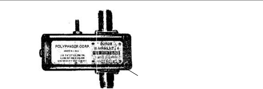
Installation Manual
Airbridge cBTS3612 CDMA Base Station Hardware Installation
7 Installing Satellite Synchronization Antenna and Feeder System
7-10
(1)
(1) PROTECTED end
Figure 7-7 Appearance of Type iS-MR50LNZ+6 lightning arrester
Notes:
l The "PROTECTED" end of the antenna-side GPS lightning arrester faces the
antenna. Namely, the "PROTECTED" end of the arrester is connected with the
jumper end;
l The antenna-side lightning arrester should not touch the ground either installed
on tower or on building top, but the grounding clip should be close to the
antenna-side lightning arrester as much as possible;
l The antenna-side lightning arrester is installed inside the lightning arrester box,
with its connectors sealed with semiconductor adhesive tape, waterproof
adhesive tape and insulating adhesive tape in sequence, so as to prevent
moisture invasion:
l The "PROTECTED" end of the equipment-side GPS lightning arrester faces the
BTS. In this case, the duplex adapter is required so that the arrester can be
connected with the set-top GPS port directly. The equipment-side lightning
arrester does not require any lightning protection grounding wire;
II. Type DGXZ+6NFNM-A lightning arrester
Figure 7-8 illustrates the appearance of Type DGXZ+6NFNM-A lightning arrester.
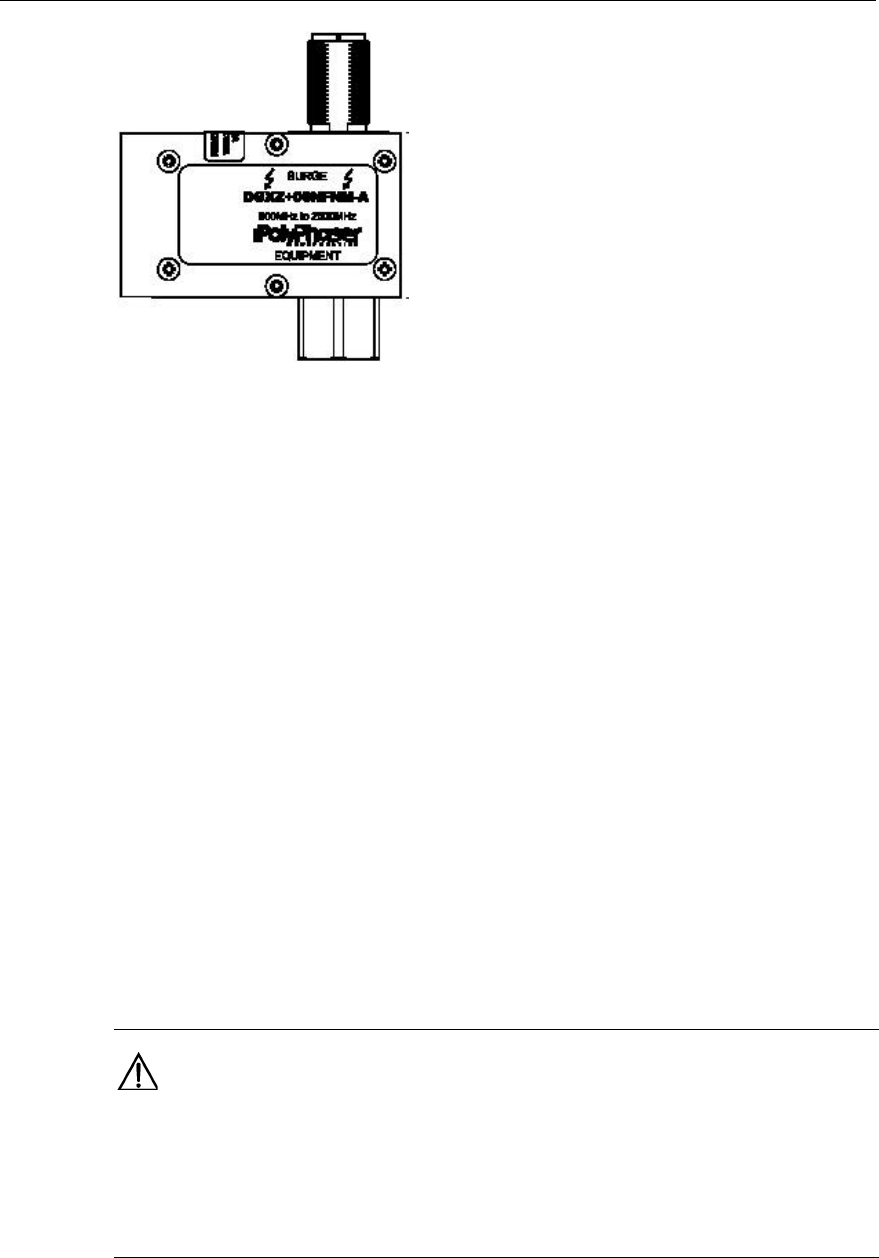
Installation Manual
Airbridge cBTS3612 CDMA Base Station Hardware Installation
7 Installing Satellite Synchronization Antenna and Feeder System
7-11
Figure 7-8 Appearance of Type DGXZ+6NFNM-A lightning arrester
Notes:
l The two connectors on the two ends of Type DGXZ+6NFNM-A lightning
arrester are respectively male and female, therefore jumpers with male and
female connectors should be available for the installation of antenna-side
lightning arrester. The male connector is connected with the GPS antenna,
while the female connector on the other end is connected male connector of the
antenna-side lightning arrester;
l The antenna-side lightning arrester should not be grounded either installed on
the tower or on building top, but the feeder grounding clip should be close to
the antenna-side lightning arrester as much as possible;
l The antenna-side lightning arrester is installed inside the lightning arrester box,
with its connectors sealed with semiconductor adhesive tape, waterproof
adhesive tape and insulating adhesive tape in sequence, so as to prevent
moisture invasion;
l The installation is completed once the equipment-side GPS lightning arrester is
connected with the set-top GPS port. The equipment-side lightning arrester
does not require any lightning protection grounding wire.
Caution:
When the distance from the antenna to the BTS is greater than 100 meters, 7/8 feeder should be
adopted so as to minimize signal loss. In this case, one end of the equipment-side antenna is
connected with the set-top GPS port, while the other end is connected with the 7/8 feeder via jumper.
This jumper has a female and a male connector respectively on its ends.
Installation Manual
Airbridge cBTS3612 CDMA Base Station Hardware Installation
7 Installing Satellite Synchronization Antenna and Feeder System
7-12
7.3.3 Feeder Grounding
Feeder routing and GPS feeder grounding installation can be conducted
simultaneously. The following part describes feeder grounding according to different
installation modes.
I. GPS antenna installed on tower
l One grounding clip is required 1 meter to the antenna lightning arrester, and
the grounding is connected with the nearest point on the tower;
l The feeder is grounded at the root of the tower. Grounding wires for the tower
root should be in the range of 0.5-1 meter above the turn of the feeder cabling
rack on the tower;
l Outside the feeder entrance to the feeder window, install a grounding clip
outside the window (at the nearest point), connect the grounding wire with the
outdoor PGND bar of the equipment room;
l If the feeder on the tower is longer than 60 meters, lightning protection clips
should be installed in the middle part of the tower, with the clip spacing as 20
meters.
II. GPS antenna installed on building top
l To install the GPS antenna on building top (independently), install a grounding
clip outside the feeder entrance to the feeder window (at the nearest point),
then connect the grounding wire with the outdoor PGND bar of the equipment
room;
l If the feeder is longer than 60 meters, lightning protection clips should be
installed in the middle part of the feeder, with the clip spacing as 20 meters.
7.3.4 Feeder Label
Figure 7-9 illustrates the standard nameplate used as GPS feeder label:
Figure 7-9 GPS feeder label
GPS feeder labels can be affixed in three positions, which are (from top to bottom):
l 0.3m to the outdoor feeder connector;
l Outside the feeder entrance to the feeder window;
l 0.3m to the indoor feeder connection.

Installation Manual
Airbridge cBTS3612 CDMA Base Station Hardware Installation
7 Installing Satellite Synchronization Antenna and Feeder System
7-13
Feeder label contents should be consistent with the silkscreen on the GPS port
connected with the set top.
7.3.5 Feeder Test
After installation, do not connect feeder and antenna with the equipment. Check the
resistance with multimeter between the feeder shield and the core. The resistance
should be several megohms at least. If short circuit is found, check whether the
feeder is damaged.
During installation, any misoperation may cause short circuit or break the conductor.
Following methods can be used to check whether the conductor is broken: Take
down the antenna, short circuit one end of the feeder shield wit the core, check the
resistance on the other end between the feeder shield and the core. If the resistance
is infinite, the feeder conductor is broken.
After confirming the feeder is damaged, find out the damaged point. It is
recommended to consult the engineering personnel. If the undamaged part is of
sufficient length, it can still be used, but a plug must be used, which can be the plug
on the original feeder.

Installation Manual
Airbridge cBTS3612 CDMA Base Station Hardware Installation
8 Hardware Installation Check
8-1
8 Hardware Installation Check
After hardware installation is finished, check it to make preparations for the
succeeding software installation and system commissioning. The hardware
installation checking covers the following aspects: Indoor equipment checking,
Antenna and feeder system checking and power-on detecting.
8.1 Checking Indoor Equipment
Indoor equipment checking is to review the indoor installation work described in the
previous chapters. The contents for checking include the following: Checking
cabinet equipments, cable distribution, and the environment of equipment room. The
contents are as follows:
8.1.1 Checking the Cabinet Equipment
This check mainly covers the following aspects:
1) After the fixing of the cabinet, the rack should be stable, level and plumb.
2) The vertical deviation of the rack should be no greater than 3 mm.
3) All the cabinet side panels facing the isle should be installed and aligned, with
the error no greater than 5 mm. The adjacent racks should stand side by side,
while the surfaces of all cabinets should be in the same plane without zigzags.
4) Screw up all screws and check that flat washers and spring washers are
correctly added.
5) The rack components should not fall off or get damaged and the connecting
cables should not be defective or broken. Each mark and label should be
correct, distinct, complete and placed at its right position.
6) The cabinet should be cleaned so as to get rid of the fingerprints after the
installation. No dusts are allowed at the dead angle inside or outside the rack.
Check the corners of the cabinet to see whether there are crushed saltpeter
and wires in installation.. Clean up the cabinet without sundries.
7) After the cables are laid and routed, the small cover plates covering the top and
bottom cable outlets should be pushed forward to prevent rodents from coming
in.
8) Check the sockets, including 12 antenna connectors on the cabinet top, 2
GPS/GLONASS antenna connectors, 1 test connector of receiving antenna,
and 5 DB9 connectors. See whether there are damaged threads, missing pins
or curved pins resulting in short circuit.

Installation Manual
Airbridge cBTS3612 CDMA Base Station Hardware Installation
8 Hardware Installation Check
8-2
9) In the case of cabinets combining, it is necessary to check whether the cabinets
are orderly and neatly arranged, whether antistatic wrist strap is installed and
cabinet door is grounded, and whether the contact of the electromagnetic
shielding layer on the side door used for the inter-cabinet cabling is tight. This
is to avoid electromagnetic leakage, which may pollute the electromagnetic
environment.
8.1.2 Checking Cable Distribution
I. Power cable
Power cables from the primary power supply connect to the input end of the power
filter on the cabinet top, and connect to the screw on the cabinet top through the
output end of the power filter, then to each backplane through cable distribution.
Every connection should be firm and well grounded with correct polarity. Use
multimeter to check the voltage and the on-off conditions of the power cables.
II. Grounding cables
Check whether the connection of grounding cables of the chassis is correct and well
grounded. Then use multimeter to measure the on-off conditions.
III. Front panel cables of the cabinet
Check if the connection of the cables within the cabinets are correct.
1) Check the GPS/GLONASS clock RF cables on the front panel of BCKM;
2) Check the power cables and alarm cables of RLDU;
3) Check the RF cables on the front panel of CDU;
4) Check the optical fiber connecting BRDM and BTRM.
Check if the cables and the heads of the optical fibers are intact and clean, if the
optical fibers are over-bent, and if the labeling is correct.
IV. Transmission cables on the cabinet top
Special check should be performed to the connection between trunk cables and the
socket on the cabinet top to see whether it is loosed.
V. Antenna and feeder connection
Check the connectors for antenna and feeder cables and jumpers, to see whether
the connectors are fastened, and whether the screw stub is rotated. Use a
Multimeter to check whether the shell of the connector is well connected with the
chassis ground. If the connection is poor, it indicates that the contact between the
flanges of the connectors and the chassis is poor.

Installation Manual
Airbridge cBTS3612 CDMA Base Station Hardware Installation
8 Hardware Installation Check
8-3
VI. Cables among cabinets
Cables among cabinets are mainly the optical fibers among cabinets. Check
whether the connection of the optical fibers is correct, whether the connectors of
optical fibers are scratched, clean and whether the fibers are over-bent, etc.
8.1.3 Checking the Environment of Equipment Room
I. Rack
There should be no excessive cable tie ends, wire leads or other sundries inside
each rack. The side panels, front and back doors of the rack should be clean without
any fingerprints or smudges.
II. Cabling trough
There should be no tie ends, stubs, desiccants or other sundries left in the cabling
trough, at the bottom of the rack or under the raised floor around the rack. All parts
of the rack should be clean and in good order.
III. Equipment room
There are no excessive articles in the equipment room; the articles necessary for
the equipment room are put in the right places; the application consoles are clean
and neat, and the raised floor (if it exists) is level and clean. After checking the
hardware installation, next start to check the power supply.
8.2 Checking the Antenna and Feeder System
8.2.1 Checking Antenna
First check whether the installation position of the antenna is in accordance with the
design, whether the antenna is under the protection of the lightning rod, and
whether the connection between antenna support and tower is reliable and firm.
Specific requirements for checking other equipment are as follows:
I. Omni antenna
1) The distance from the omni antenna to tower body should not be less than 2m.
2) When omni antenna is installed horizontally, the horizontal spacing between the
transmitting antenna and the receiving antenna should not be less than 3m.
3) When omni antenna is installed vertically, the vertical spacing between the
transmitting antenna and the receiving antenna should not be less than 0.2m.

Installation Manual
Airbridge cBTS3612 CDMA Base Station Hardware Installation
8 Hardware Installation Check
8-4
4) The horizontal spacing between omni receiving antennae should not be less
than 4m.
5) Top-end of the jacket of omni antenna should be of the same height with the
support or a little higher than the top of the support.
6) The omni antenna should be vertically erected, and the error should be less
than ±2 degrees.
7) If the omni antenna is installed at the roof, the horizontal spacing between the
omni antenna and the antenna lightning rod should not be less than 2.5m.
II. Directional antenna
1) The distance from the directional antenna to the tower body should be no less
than 1m.
2) When the directional antenna is installed horizontally, the horizontal spacing
between transmitting antenna and the receiving antenna in the same sector
should be no less than 5.3m.
3) When the directional antenna is vertically installed, the vertical spacing
between the transmitting antenna and the receiving antenna in the same sector
should be no less than 0.2m.
4) The horizontal spacing between the transmitting antenna and the receiving
antenna in the different sectors should be no less than 0.2m.
5) For single-polarized antenna, the horizontal spacing between the transmitting
antenna and the receiving antenna of the directional antenna should be no less
than 4m.
6) The error for azimuth of the directional antenna should be no more than ±5
degree. And the error for pitch angle should be no more than ±0.5 degree.
III. GPS antenna
1) GPS antenna should be kept vertically erected, with the visual angle more than
90°.
2) GPS antenna should be away from radiation range of the directional antenna
with frequency over 400MHz, and power over 1W. The distance away from the
omni transmitting antenna should be over 20m.
3) GPS antenna should be under the valid protection of the lightning rod. And the
horizontal spacing between the antenna and the lightning rod should be 2~3m.
Caution:
After the antenna is installed, power on the BTS. To ensure that PN code of the cell is correct, and the
cell is installed properly, use the test MS to perform the test around the cell. Then make sure that the
tested PN code is in accordance with the PN code in the PN code distribution map of "Network
Planning Report". If inconvenient for testing at the site, check the configuration data of the cell directly.

Installation Manual
Airbridge cBTS3612 CDMA Base Station Hardware Installation
8 Hardware Installation Check
8-5
8.2.2 Checking Feeders
1) Feeders should be neatly and orderly arranged.
2) Attach feeder and jumper labels according to the specifications. The labels
should be neatly arranged in the same direction.
3) The feeder should be without obvious traces of bending or twisting. No naked
copper is found on the feeder.
4) The feeder’s minimal bending radius should be no less than 20 times the feeder
radius.
5) The spacing among feeder fixing clips should be evenly in the same direction
after completing the installation.
6) In the case of feeder being led indoors, the length of outdoor flat part should be
more than 0.5 m. The flat part at both sides of lightning arrester rack should be
at least 0.3 m.
7) The feeder distribution should have no intersections, and keep neat row and
column with consistent bending.
8) All outdoor jumper connectors should be processed with waterproof sealing.
The jumper should be prepared with waterproof curve.
9) The jumper that connects to the antenna should be bound on the iron rack of
the tower along the support crossbeam.
10) If the front of cabinet is parallel with the feeder indoor cabling direction, or the
back of cabinet is exactly facing the feeder indoor cabling direction, one sector
should be in one row, and the sequence of each row should be consistent. If
the front of the cabinet is facing the feeder indoor cabling directions, one sector
should be in one column, and the sequence of each column should be
consistent.
11) When installing feeder window on the roof, and leading the feeder into the room,
ensure the feeder window be tightly sealed.
12) The quality of the feeder connector should conform to the specification, without
loose connections.
13) The main feeder is correctly connected and the sector is correct.
8.2.3 Checking the Sealing Window
1) The glue-inserting hole on the sealing suite of the sealing window should be
place upwards. The sealing window plate should be installed indoors at one
side (In the case of the window of later version, this item is not needed).
2) When leading the feeder into the room through the sealing window on the
building-top, the sealing window should be well sealed.

Installation Manual
Airbridge cBTS3612 CDMA Base Station Hardware Installation
8 Hardware Installation Check
8-6
8.3 Power-on Checking
Before switching on the primary supply, use the resistance range of a multimeter to
check various power supplies on the cabinet top and the studs on the ground for
any short circuit.
8.3.1 Power-on Test of the Power Modules
Make sure that all power modules are correctly inserted into the backplanes, and
none of the other boards, modules or units (such as BTRM, BHPA, RLDU, BRFM,
etc.) are inserted into the slots of the backplanes. Switch on the primary power
supply on the module of rectifier equipment to see whether the output voltage of the
secondary power supply is normal, and whether the indicators of all power modules
are normal. Measure the output voltages of the power supply module at the voltage
test point with a multimeter to see whether the output voltages are stable and within
the range of indexes. If not, switch off the primary power supply, clear the fault and
power on it again until everything is normal.
8.3.2 Power-on Test of the Integrated Equipment
Turn off all the power supply switches on the switch box, and make sure that all
boards and modules are inserted into the slots of the backplane.
Turn on all the power supply switches on the switch box in turn, and power on every
board and module one by one. Observe the running of boards and modules. Power
off the power supply immediately for any exception. Power on all the boards and
modules as above after the fault is clear.
If each module/board is in normal status, the primary test on the status of boards
and modules is successfully finished.