Huawei Technologies CBTS3612-1900 CDMA Base Station User Manual 00 Table of Contents
Huawei Technologies Co.,Ltd CDMA Base Station 00 Table of Contents
Contents
- 1. User Manual
- 2. Maintenance Manual
- 3. Installation Manual Part 1
- 4. Installation Manual Part 2
- 5. Installation Manual Part 3
Installation Manual Part 3

Installation Manual
Airbridge cBTS3612 CDMA Base Station Software Installation & System Commission
Table of Contents
i
Table of Contents
1 Overview of Software Installation.....................................................................................1-1
1.1 Overview of Software Installation ...............................................................................1-1
1.1.1 BTA Operational Software ...............................................................................1-1
1.1.2 Terminal Maintenance Software.......................................................................1-3
2 Installing Terminal Maintenance Software........................................................................2-1
2.1 Characteristics of Terminal Maintenance Software......................................................2-1
2.2 Installing Local Maintenance Software .......................................................................2-1
2.2.1 Operational Environment .................................................................................2-1
2.2.2 Precautions.....................................................................................................2-2
2.2.3 Network Configuration.....................................................................................2-2
2.2.4 Software Installation and Instructions ...............................................................2-2
2.3 Installing Remote Maintenance Software....................................................................2-3
2.3.1 Operational Environment .................................................................................2-3
2.3.2 Precautions.....................................................................................................2-3
2.3.3 Software Installation Instructions ......................................................................2-3
3 Installing the BTS Operational Software...........................................................................3-1
3.1 Introduction to Software Media...................................................................................3-1
3.2 Changing Chip to Install Software..............................................................................3-2
3.3 Loading Software......................................................................................................3-2
3.3.1 Methods of Software Loading...........................................................................3-2
3.3.2 Remote Loading of BTS Software....................................................................3-3
3.3.3 Local Loading of BTS Software........................................................................3-6
3.3.4 Verifying the Software Version .........................................................................3-7
4 System Commissioning ....................................................................................................4-1
4.1 Introduction to the Modes of System Commissioning..................................................4-1
4.1.1 Local Commissioning ......................................................................................4-1
4.1.2 Remote Commissioning...................................................................................4-1
4.2 Power-on Operation Process of Software...................................................................4-2
4.2.1 Startup of Boards and Description of Indicators ................................................4-2
4.2.2 Automatic Interception of BCIM Board..............................................................4-3
4.2.3 Create OML Link .............................................................................................4-3
4.2.4 Setting up Abis Signaling Link..........................................................................4-3
4.2.5 Setting Up Cells ..............................................................................................4-3
4.2.6 Normal Operational States...............................................................................4-4
4.2.7 Description of the Clock Reference Source.......................................................4-4
4.3 Basic Operations.......................................................................................................4-4

Installation Manual
Airbridge cBTS3612 CDMA Base Station Software Installation & System Commission
Table of Contents
ii
4.3.1 Daily Maintenance...........................................................................................4-4
4.3.2 Equipment Control...........................................................................................4-6
4.4 Commissioning Board Software ...............................................................................4-10
4.4.1 Testing Links.................................................................................................4-10
4.4.2 Processing Faults and Alarms........................................................................4-10
4.4.3 Operation and Maintenance...........................................................................4-12
4.5 Call Function Test ...................................................................................................4-17
4.5.1 Test Equipment .............................................................................................4-17
4.5.2 Preparations for Service Function Test...........................................................4-18
4.5.3 Service Flow Overview..................................................................................4-18
4.5.4 Testing Location Updating Flow.....................................................................4-20
4.5.5 Testing MS Originated Call Flow....................................................................4-20
4.5.6 Testing MS Terminated Call Flow...................................................................4-20
4.5.7 Testing Handover Flow..................................................................................4-21
4.5.8 Testing MS Originated SM Flow.....................................................................4-22
4.5.9 Testing MS Terminated SM Flow ...................................................................4-22
4.5.10 Testing MS Originated Packet Data Flow......................................................4-23
4.5.11 Testing MS Packet Data Flow (Downstream Service Rate)............................4-23
4.5.12 Processing the Abnormalities in the Test ......................................................4-24

Installation Manual
Airbridge cBTS3612 CDMA Base Station
Software Installation & System Commissioning
1 Overview of Software Installation
1-1
1 Overview of Software Installation
The chapter gives a brief introduction to BTS operational software and BTS terminal
O&M software, including installation of all the software.
1.1 Overview of Software Installation
Since FPGA logic is to be loaded and upgraded, the related description of FPGA will
be given, too.
cBTS3612 software include BTS operational software and terminal maintenance
software.
I. BTS operational software
BTS operational software includes BOOT software, CPU software, and FPGA logic.
Based on its varied functions, CPU software can be further divided into BCKM
software, BCIM software, BCPM software, BRDM software, and BTRM software.
II. Terminal maintenance software
Terminal maintenance software includes local maintenance console software (LMF
software) and remote O&M software (OMC software). Currently, LMF software
comprises Telnet software of PC out-of-box and FTP software. While OMC software
is composed of BAM software and Client software.
1.1.1 BTA Operational Software
I. BOOT software
BOOT software serves the startup of the board. Before delivery of BTS, BOOTROM
in every board has already been installed with startup software. Generally, the
BOOT software upgrading is realized by changing the chips.
II. CPU software
The loading of CPU software includes the following two modes:
l If there is no old-version software on the board, the board is required to load
the software through board network port under the commissioning mode.

Installation Manual
Airbridge cBTS3612 CDMA Base Station
Software Installation & System Commissioning
1 Overview of Software Installation
1-2
l If there is existing software on the board, the software will be upgraded under
the instruction of the commands from local FTP software or remote O&M
software.
CPU load software of all boards is saved in Flash Memory of BCKM. When the BTS
is powered and running, CPU software is loaded to RAM for operation.
The following introduces the CPU software of all boards:
1) BCKM software
The software runs on BCKM board, including three parts: OMU, CLK and MC,
respectively as follows:
OMU is O&M software. It is mainly to complete the configuration of BTS, by
cooperating with OMC or through local maintenance console. In this case, O&M
functions of BTS are achieved.
As clock software, CLK aims to provide clock reference for BTS according to clock
reference source.
As the controlling software, MC mainly completes signaling exchange between BTS
and BSC, resource allocation/release and call proceeding, etc.
2) BCIM software
Running on the BCIM board, BCIM software aims to create ATM transmission link of
the Abis interface (i.e. the interface between BTS and BSC), and is responsible for
transmitting the signaling, service information, and O&M information between BTS
and BSC through the relevant protocol stacks.
3) BCPM software
The software runs on the BCPM board to control the operations of the chip for
channel processing. Together with the controlling software, it also realizes the
management of traffic layer of channel processing unit. Additionally, the software
processes the common channels, and traffic channels.
4) BRDM software
BRDM software runs on the BRDM board, to complete the signaling trunk and O&M
information trunk of BTRM module, and the baseband data trunk of BCPM board.
5) BTRM software
The software runs on the BTRM module, together with the controlling software and
O&M software, to realize the configuration management of BTRM module, and
complete the conversion of intermediate frequency signals and RF signals.
III. FPGA logic
BCPM board, BRDM board and BTRM module of cBTS3612 are required to load
FPGA logic. The loading mode is the same as that of CPU software.

Installation Manual
Airbridge cBTS3612 CDMA Base Station
Software Installation & System Commissioning
1 Overview of Software Installation
1-3
1.1.2 Terminal Maintenance Software
I. Local maintenance software
Generally, local maintenance console is a portable computer installed with
Windows9x OS, the O&M software of which includes FTP Client (Ftp.exe) and
Telnet Client (Telnet.exe). The two programs can perform hierarchical maintenance
of BTS objects, including site, cells, baseband, carriers, channels, etc. through MML
command. Since the two programs are self-contained by Windows9x OS, it is
unnecessary to install them again.
II. Remote maintenance software
Remote O&M software (OMC) of the Base Station Subsystem (BSS) adopts the
Client/Server structure. The user inputs operation commands through the Client. As
a server, BAM performs centralized processing of the command messages from
different Clients. After being processed by BAM, these command messages are
transmitted to the foreground (including BSC and BTS). After the foreground returns
a response, BAM will record the results (success, failure, timeout, exception, etc.) of
the operations and will then transmit the returned results of the operations in a
certain report format to the Client, thus to inform the client of the results of the
operations.
The user can perform remote maintenance and monitoring of all BTSs in the charge
of himself, meanwhile, he can collect all site information for integrated network
planning.

Installation Manual
Airbridge cBTS3612 CDMA Base Station
Software Installation & System Commissioning
2 Installing Terminal Maintenance Software
2-1
2 Installing Terminal Maintenance Software
This chapter first introduces the characteristics of terminal maintenance software of
cBTS3612, and then covers the operation environment and precautions for
installation.
2.1 Characteristics of Terminal Maintenance Software
Based on different requirements, cBTS3612 terminal O&M software (hereinafter
referred to as "terminal maintenance software") comprises remote maintenance
software and local maintenance software. There is slight difference in installation
files and modes between the two types of software.
I. Local maintenance software
Local maintenance software includes FTP Client (Ftp.exe) and Telnet Client
(Telnet.exe). Since the two programs are both self-contained by Windows9x OS, it is
unnecessary to install them again.
When performing local maintenance, the local maintenance console should be
connected to the Ethernet interface of the BCKM board of cBTS3612.
II. Remote maintenance software
Remote maintenance software includes BAM server software and Client software.
And the latter is composed of BSC Client software and BTS Client software.
Generally, remote maintenance software should be installed when installing BSC.
Remote maintenance software mentioned in this manual mainly refers to the BTS
part of Client software.
2.2 Installing Local Maintenance Software
2.2.1 Operational Environment
I. Hardware environment
Basic hardware configuration of the WS (desk-top computer)
l Pentium 100 CPU
l 1×500M hard disk
l 1×8MB memory

Installation Manual
Airbridge cBTS3612 CDMA Base Station
Software Installation & System Commissioning
2 Installing Terminal Maintenance Software
2-2
l 1× integrated network card
II. Software configuration
Windows 95 or Windows 98.
2.2.2 Precautions
For the local maintenance console, following requirements should be observed:
1) Hardware environment is well and stable.
2) Windows9x OS can operate normally.
3) Windows9x installation files and network card driver (provided by the original
manufacturer) are furnished.
2.2.3 Network Configuration
Configuration of local maintenance network includes the installation and
configuration of network cards, installation and configuration of TCP/IP. The
configuration is realized through “Add new hardware” and “network” in turn on the
control panel of the computer.
IP address of the maintenance console should be within the same network segment
as that of network interface of BCKM board of BTS. Additionally, the address should
be unused by other equipment in the network.
The sequence of connection of network cables(Crossover Cable) at the network
interface is shown in Table 2-1.
Table 2-1 Network interface connection
BTS side connector 1 2 3 4 5 6 7 8
PC side connector 3 6 1 4 5 2 7 8
2.2.4 Software Installation and Instructions
Local maintenance software (Ftp.exe and Telnet.exe) is self-contained by
Windows9x. It is unnecessary to install it additionally.
To run Ftp and Telnet: click the [Start/Running] in the system menu of the computer,
and input “ftp xxx.xxx.xxx.xxx” and ”telnet xxx.xxx.xxx.xxx” into the dialogue box of
“run”. “xxx.xxx.xxx.xxx” is the IP address of BCKM network interface. Then log on
the BCKM board.

Installation Manual
Airbridge cBTS3612 CDMA Base Station
Software Installation & System Commissioning
2 Installing Terminal Maintenance Software
2-3
2.3 Installing Remote Maintenance Software
2.3.1 Operational Environment
Operational environment of remote maintenance software (referring to BTS part of
Client software only) is based on the platform that has been installed with Client
software BSC part. Hardware environment and software configuration are not
required additionally.
2.3.2 Precautions
1) Make sure that no any software program not necessary for the operating
system has been installed on the computer; Otherwise, it may lead to
operational conflicts that may cause the MML client software to run unstably or
not run at all. Moreover, make sure that a stable and good network hardware
environment has been established.
2) Obtain a complete set of installation files and readme files provided by Huawei,
as well as a legal product serial number.
3) BTS part of Client software should be installed on the basis that the
corresponding BSC part has been already installed. Note the corresponding
relationship between versions of the two before installation.
2.3.3 Software Installation Instructions
After installing the BSC part of client software, corresponding BTS part should be
installed. For installation of client software BSC part, please refer to the relevant
content of “Software Installation” module in “AirBridge cBSC6600 CDMA Base
Station Controller Installation Manual”. Following specifically introduces the
installation of client software BTS part:
I. Starting SETUP.EXE
Insert the installation disk into the disk drive. If auto execution has been set for the
system, the program will begin starting. Otherwise, select the submenu [Run (R)]
from [Start] menu of the Windows and key in “<SETUP>“ (key in the corresponding
driver symbol and path if it is not the current path), then press <Enter>. The
installation program will start. Or use the Resource Manager to browse and run the
file “SETUP.EXE”. You can also copy the files in the installation disk to the same
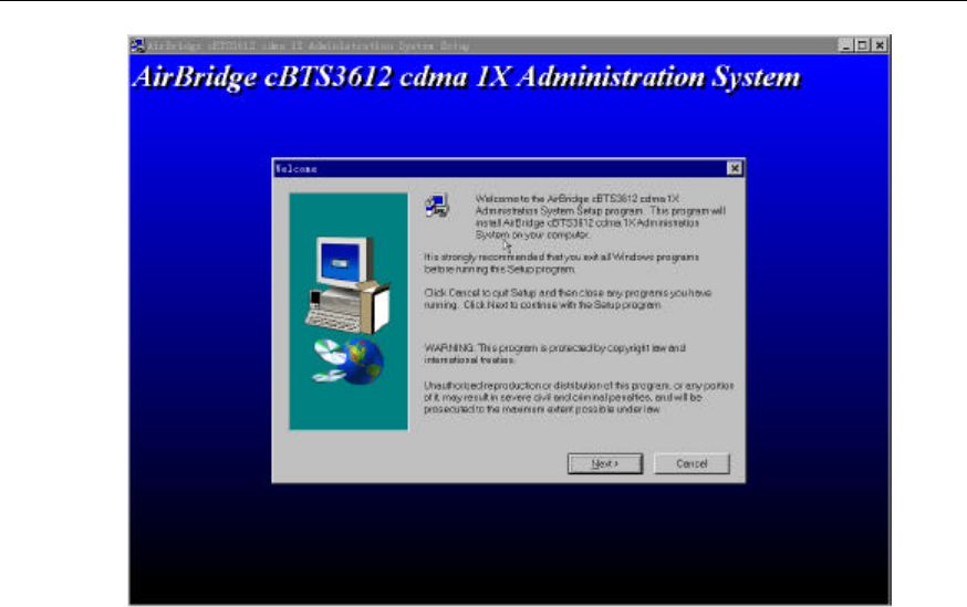
directory and run them. Then there appears a [Welcome] window as shown in
Figure 2-1.
Installation Manual
Airbridge cBTS3612 CDMA Base Station
Software Installation & System Commissioning
2 Installing Terminal Maintenance Software
2-4
Figure 2-1 Initial installation interface
Click <Next> to continue. Or click <Cancel> to exit the installation.
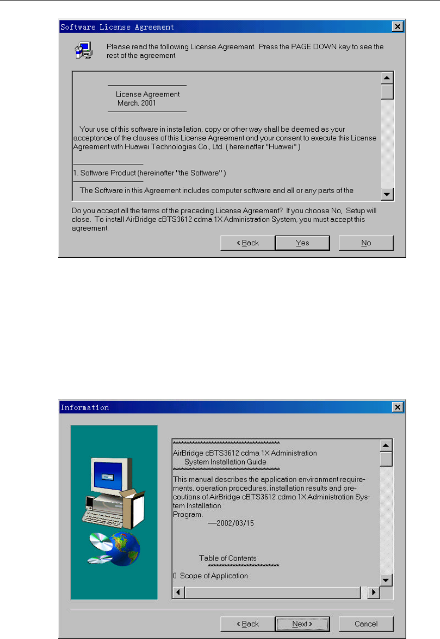
II. License agreement and installation instructions
The Software License Agreement is shown in Figure 2-2. Read it carefully and
confirm your acceptance for the agreement. Click <Yes> to continue (or <No> to exit
the installation).
Installation Manual
Airbridge cBTS3612 CDMA Base Station
Software Installation & System Commissioning
2 Installing Terminal Maintenance Software
2-5
Figure 2-2 Software license agreement interface
What followed is a system installation guide provided by the installation program,
showing the steps of the BTS management system and some supplementary
information on installation as shown in Figure 2-3. It might contain some latest
installation information not given in this manual. Please read it carefully, Then click
<Next> to continue.
Figure 2-3 Interface of system installation instructions
Installation Manual
Airbridge cBTS3612 CDMA Base Station
Software Installation & System Commissioning
2 Installing Terminal Maintenance Software
2-6
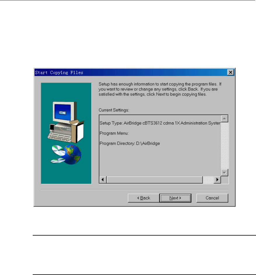
III. Confirming the installation information
You are required to confirm the installation information by installation program as
shown in Figure 2-4, then to copy the files. If you want to change the installation
information, please click <Back> to return to the previous step, or click <Next> to
continue.
Figure 2-4 Confirming the installation information
&
Note:
The default installation path for AirBridge CDMA 1X BTS Administration System is D:\AirBridge, that is,
the same as that of BSC. If the installation path of BSC changes, BTS will find it for installation.
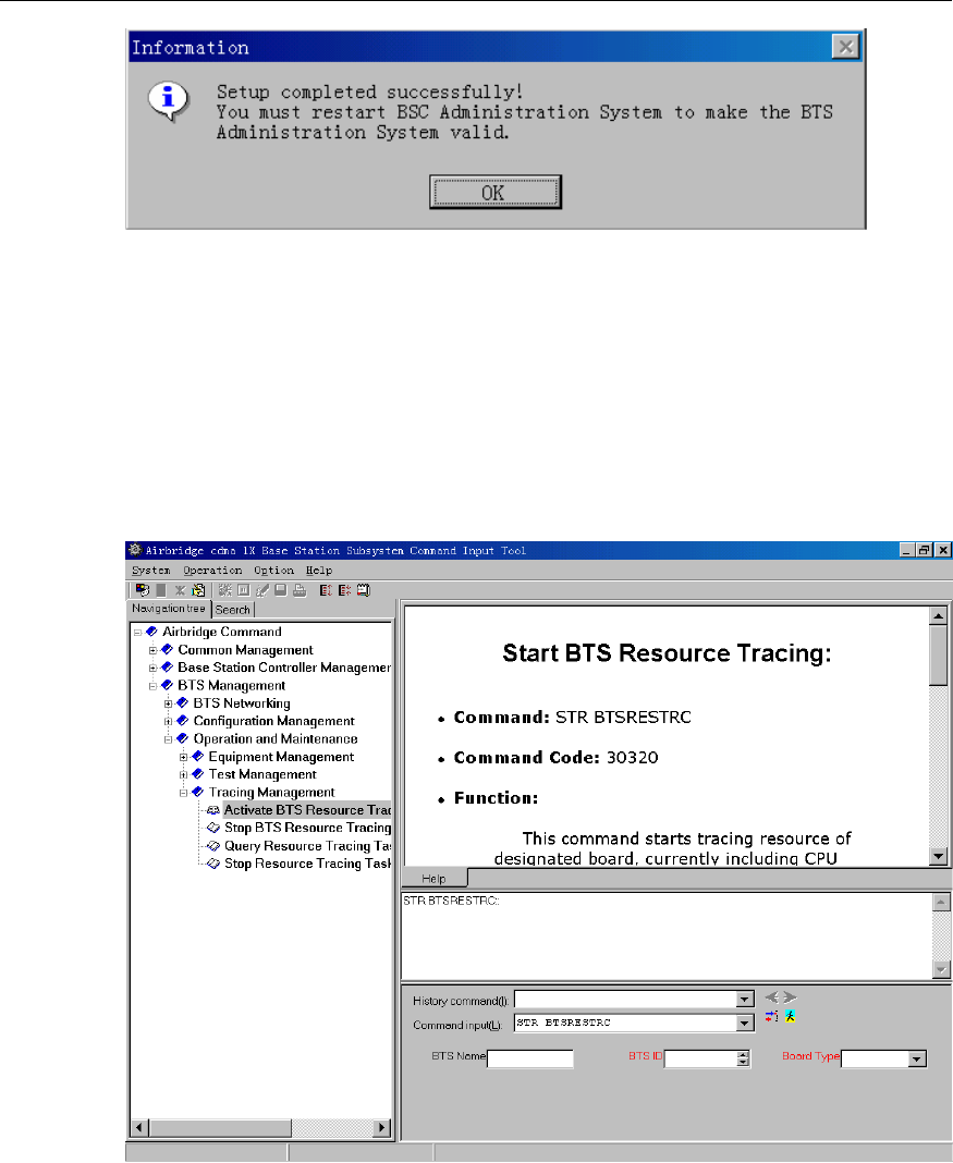
IV. Completing the installation
After confirming the installation information, the installation program starts to copy
the files. In the process of copying files, the installation program will display the
whole copy progress, available disk space, available memory, copy progress of
individual files, etc. Then the installation program will pop up a window indicating
that the setup is completed successfully, as shown in Figure 2-5. The client software
should be restarted to validate the BTS part.
Installation Manual
Airbridge cBTS3612 CDMA Base Station
Software Installation & System Commissioning
2 Installing Terminal Maintenance Software
2-7
Figure 2-5 End of the installation
Up to now, the installation of AirBridge CDMA 1X BTS Administration System is
completed entirely.
After the installation, under the program menu of ”Airbridge cBSS cdma 1X
Administration System” program group (default), click the submenu ” AirBridge
cBSS Client” to start client software. The operation interface is shown in Figure 2-6.
Figure 2-6 Operation interface of remote maintenance software

Installation Manual
Airbridge cBTS3612 CDMA Base Station Software Installation & System Commissioning
3 Installing the BTS Operational Software
3-1
3 Installing the BTS Operational Software
This chapter first introduces the operational software of cBTS3612 according to
different software media, then based on different load path, covers the remote load,
local load, and software version verification of BTS operational software, etc.
3.1 Introduction to Software Media
cBTS3612 software has two kinds of media:
1) Memory chip
2) Disk file
The specific software is described as follows:
I. BOOT software
It is board-boot software, including the most elementary initialization of board
hardware. Before delivery, BOOTROMs of all boards are pre-installed with BOOT
software. Generally, BOOT software upgrading is achieved by means of chip
change.
II. CPU software
As the high-layer software of the board, CPU software is the core of the system
function. Before delivery of BTS equipment, CPU software has been loaded to Flash
Memory. After the equipment is power-on, BOOT software is responsible for loading
CPU software to RAM for operating from Flash Memory.
When it is required to reload CPU software or upgrade the software during the
maintenance process, CPU software in disk file format might be loaded to the
corresponding Flash Memory through the remote or local maintenance console.
III. FPGA logic
FPGA logic mainly completes the functions such as data exchange of boards, etc.
Media of all boards are different, but the process to load an FPGA logic should be
the same as that of loading CPU software.

Installation Manual
Airbridge cBTS3612 CDMA Base Station Software Installation & System Commissioning
3 Installing the BTS Operational Software
3-2
3.2 Changing Chip to Install Software
Generally, we replace the chip to update the BOOT software. Just replace the
program chip of the old version software with the chip of the new version.
Caution:
1) The four angles of the chip correspond to those of the socket. Make sure there is no mistake when
replacing the chip, and the angles of both the chip and the socket are in accordance. Other wise, the
chip might be burned.
2) Generally, Huawei engineers are responsible for replacing the chip.
3.3 Loading Software
Apart from that the boot software of BTS system is upgraded through replacing the
memory chip, common board software (including CPU software and FPGA logic) are
installed and updated by downloading the software.
3.3.1 Methods of Software Loading
BTS software loading can be realized through remote maintenance console or local
maintenance console.
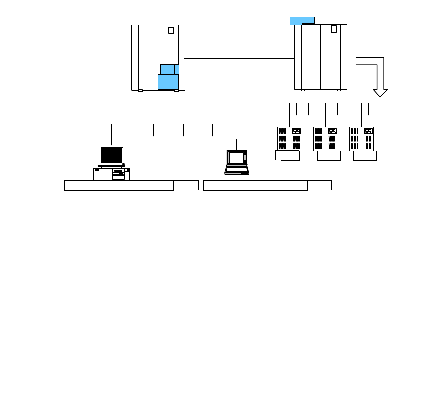
Remote maintenance console is connected to BSC via LAN, then through IPOA link
of BSC, connected to OMU (operation &maintenance unit) on BCKM board of
cBTS3612, finally, from the BCKM board, it is connected to all BTS boards.
Local maintenance console is connected to BCKM board (there is a 10/100 Base-T
Ethernet interface on the panel of BCKM board) via the Ethernet interface. Then
through the BCKM board, it connects to all boards of BTS.
The connection relationship between BTS remote maintenance console and local
maintenance console is shown in Figure 3-1.
Installation Manual
Airbridge cBTS3612 CDMA Base Station Software Installation & System Commissioning
3 Installing the BTS Operational Software
3-3
BSC
BTS
Abis
Remote maintenance console of BTS Local maintenance console of BTS
BCKM BoardBoard
BAM
Figure 3-1 Connection of the maintenance consoles
It is quite convenient to load board software to cBTS3612 through remote
maintenance console or local maintenance console.
&
Note:
The files to be downloaded can be saved to any directory of the floppy disk or hard disk. Specific file
path and file name will not affect the correctness of the downloading and activating. However, it is still
recommended the names of directories and files should carry distinct information on types and
versions (such as, OMU1107.bin indicating the binary file of OMU Nov. 7 Version) to avoid confusion
and version error.
3.3.2 Remote Loading of BTS Software
I. Overview
The system provides the function of remote loading to realize the installation and
version upgrading of BTS software. Thus the maintenance personnel can load
software to the board of BTS through the remote maintenance console. Software
loading includes downloading and uploading. While the downloading still comprises
two steps:
1) Downloading BTS software;
2) Activating BTS software.
The maintenance personnel downloading the software from BAM to BCKM board of
BTS through remote maintenance console. BCKM board saves the downloaded
software in the memory, then activates the software to complete the entire loading.

Installation Manual
Airbridge cBTS3612 CDMA Base Station Software Installation & System Commissioning
3 Installing the BTS Operational Software
3-4
If the downloaded software is BCKM software, when the BCKM software is activated,
BTS will be reset and BCKM will restart the newly-loaded software; if the loaded
software is the software of other BTS boards and when it is activated, BCKM board
will load the corresponding board software saved in the memory just now to the
specific board. When the board receives the new software, it will activate the new
software by resetting itself and complete the software loading.
II. Precautions for the loading
1) Load sequence
Software loading should be carried out based on the actual conditions. According to
the version auxiliary table, it first load the firm software (mainly boot software), then
FPGA software, and finally, the CPU software.
Since the firm software is generally loaded by replacing the chip in off-line status,
there is no sequence for the loading.
Software loading of boards should follow the following sequence:
BTRM->BRDM->BCPM->BCIM->BCKM. While loading software to the specific
board, the sequence of “FPGA first, then CPU” should be followed.
2) Solutions
l Successful downloading but fail to activate
Incorrect parameter for software downloading command and wrong software version
No. may result in successful downloading but failing to activate the software.
Therefore, the correct software version No. must be available.
l Unsuccessful loading
First make sure the loading sequence is correct and then start to check: whether
FTP server of BAM is on; whether the directory to be accessed is authorized for
access; whether the user name and password are correct; whether there is the
directory or file to be accessed.
III. Specific process of software loading
1) Preparation for software downloading
Copy the BTS board software to be downloaded to the directory for BTS software
loading, which is designated in the BAM. Make sure that the attributes of the file
must be writable and readable, and meanwhile record the version information of the
software.
2) Create the information for software loading in the remote BTS maintenance
system
Run the remote maintenance console software (Airbridge cBSC6600 cdma 1X
Administration System Client), and select <BTS Management> in the command
tree. Execute <Add BTS Loading Information (ADD BTSLDINFO)> on the

Installation Manual
Airbridge cBTS3612 CDMA Base Station Software Installation & System Commissioning
3 Installing the BTS Operational Software
3-5
<Macro BTS Loading Management> of <Macro BTS Management >, click the
shortcut of <Create Input Interface> , then input as the following steps:
Select the type of the board to be created with loading information in [Board Type].
Select the type of board software in [Software Type].
Input the version No. of the software to be downloaded into [Software Version No.]
(Version No. of the software must meet the specification).
Input the path of the software to be loaded (i.e. the directory for loading in the
previous step) into [Path of File Loaded].
Input the name (the corresponding file name under the software loading directory in
the previous step) of the corresponding file to be loaded into [Name of File
Loaded].
Click the shortcut of <Execute Command> to create the information for
software loading of the corresponding board.
3) Operations for software downloading
Execute <Download BTS Software or Data Operation (DLD BTSSW)> on the
<Macro BTS Loading Management> of <Macro BTS Management >, click the
shortcut of <Create Input Interface> , and then input as the following steps:
Input the name of the BTS to download the software into [BTS Name] (this step
may be ignored).
Input the ID of the BTS to download the software, into [BTS ID].
Select the activation mode of the software to be downloaded from [Software
Activation Mode].
Select the object type of the software to be downloaded from [Object Type].
Select the software type of the corresponding object from [Software Type].
The information that is input into [Software Version] must be in accordance with
the version No. of the software that has created the corresponding loading
information.
Select the number of the BTS board to be downloaded from [Board ID].
Click the shortcut of <Execute Command> to download the software of the
corresponding board. If this operation is successful, BTS is to download the
corresponding software to BTS BCKM board and save it. Then the software on
BCKM will be downloaded to the specified board and the loading progress will be
shown with a step length of 5%. When the step length for loading progress reaches
100%, it indicates the software has been downloaded to the specified boards of the
BTS from the BCKM board. Then, the board will verify the validity of the software
Installation Manual
Airbridge cBTS3612 CDMA Base Station Software Installation & System Commissioning
3 Installing the BTS Operational Software
3-6
downloaded and perform the format conversion of the software, write it into Flash
Memory, and activate it by resetting. Finally, a period of time later, related indication
will show that the downloading is successful.
4) Operations for software uploading
Execute <Load BTS Data Operation (ULD BTSSW)> on the <Macro BTS Loading
Management> of <Macro BTS Management >, click the shortcut of <Create Input
Interface> , and then input as the following steps:
Input the name of BTS to upload the software into [BTS Name] (this step may be
ignored);
Input the ID of the BTS to upload the software into [BTS ID].
Select the object type of the software to be uploaded from [Object Type];
Click the shortcut of <Execute Command> to upload the corresponding BTS
configuration data. If this operation is successful, BTS is to run FTP to upload the
data information of the specified version to the remote BAM, and save it under the
file loading path designated when creating the information of software loading.
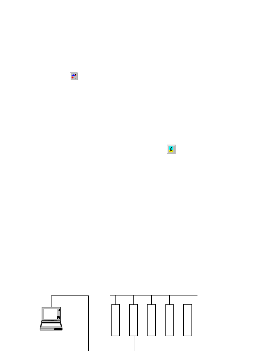
3.3.3 Local Loading of BTS Software
I. Overview
If there is the program in old version on the board, and it can still run normally,
software/FPGA logic can be loaded and upgraded in this way.
The connection for local loading is shown in Figure 3-2.
PC
Network cable
BCIM
BCKM
BRDM
BCPM
BTRM
Figure 3-2 Local loading connection

Installation Manual
Airbridge cBTS3612 CDMA Base Station Software Installation & System Commissioning
3 Installing the BTS Operational Software
3-7
II. Specific steps to download the software saved in the local maintenance
console
1) When the BTS is power-on, and runs normally, login to OMU of the BCKM
board through the local FTP of PC.
Before the operation, get the IP address of network interface of BCKM board, then
key in the following in the DOS environment: “ftp xxx.xxx.xxx.xxx”. Here the
“xxx.xxx.xxx.xxx” is the IP address of the network interface of BCKM board. Then
input the user name and the password to complete the login according to the
prompt.
2) Input the command of <Put File Name>, and the path of the file should be
designated in the file name.
3) Input the command of <Literal Act Board Software ID>, and activate the
downloaded software/logic of the corresponding board. For example: ”literal act
brdm.fpg 0”. What is activated in this example is the FPGA software of BRDM
0.
4) Input <Literal Result> to view whether the activation of the software is
successful.
3.3.4 Verifying the Software Version
Originate a query through the remote maintenance console or the local maintenance
console to get the version information of the running software of BTS boards.
I. Get the version information of board software via the remote maintenance
console
Start the remote maintenance console software (Airbridge cBSC6600 cdma 1X
Administration System Client), and Select <BTS Management> in the command
tree. Then execute <Query BTS Board Version Information (DSP BTSBRDVER)>
on the <Macro BTS Equipment Management> of <Macro BTS Management>,
click the shortcut of <Create Input Interface>, and finally input as the following
steps:
Input the name of the BTS to be queried into [BTS Name] (this step may be
ignored).
Select the ID of the BTS to be queried from [BTS ID].
Select the BTS board to be queried from [Board Type].
Select the number of the BTS board to be queried from [Board ID].
Click the shortcut of <Execute Command> to get the result of the query in BTS
board version information in the maintenance window;

Installation Manual
Airbridge cBTS3612 CDMA Base Station Software Installation & System Commissioning
3 Installing the BTS Operational Software
3-8
II. Get the version information of every board via the local maintenance
console
Start Telnet at the local maintenance console and input the command under the
prompt character after the login:
DSP BTSBRDVER: BRDTP=<BCKM>, BRDID=<0>
BRDTP is the board type to be queried, BRDID is the board ID to be queried. The
version information of every board can be attained via this command at the local
maintenance console.

Installation Manual
Airbridge cBTS3612 CDMA Base Station Software Installation &
System Commissioning
4 System Commissioning
4-1
4 System Commissioning
System commissioning is of importance to software installation and system
commissioning. This chapter first gives a brief introduction to the modes for system
commissioning, then covers the power-on operation process of the software, basic
operations, and finally describes board software commissioning and call function
test.
4.1 Introduction to the Modes of System Commissioning
4.1.1 Local Commissioning
Local commissioning is mainly performed via BTS local maintenance console. Log
in to BTS using the Telnet mode, and commission the BTS objects via MML
command. Refer to the module of “Introduction to Terminal Maintenance Console” in
User’s Manual for details of commissioning commands.
4.1.2 Remote Commissioning
I. Commissioning via OMC
It indicates that user inputs the command for commissioning at the client; in receipt
of the command, BAM server will process it and send it to BTS. When the response
returns from the BTS, the BAM server will record the operation result (success,
failure, timeout, exception, etc.) and send the returned operation result in a certain
report format to the client to inform the client of the result, thus end the
commissioning. For specific operations, please refer to “BSS Operation Manual”.
II. Commissioning via Modem dialing
The client can use a Modem which is connected to the serial port on the cabinet-top
of cBTS3612, as a dialing server. Thus, the client can log in to BTS via remote
dialing and perform remote commissioning on BTS objects by using the Telnet mode.
The specific operations after the login are the same as those in local
commissioning.

Installation Manual
Airbridge cBTS3612 CDMA Base Station Software Installation &
System Commissioning
4 System Commissioning
4-2
4.2 Power-on Operation Process of Software
With cBTS3612 powered on, every board software performs self-test and the
necessary initialization. When the software runs normally and stably, they start to
request OMU for configuration.
OMU gets the basic configuration parameters of BTS, creates the necessary
connections, and judges whether there are correct configuration data in the local
Flash Memory of BTS via BOOTP protocol (a standard protocol in TCP/IP protocol
family, which can automatically get IP). If the correct configuration data exist, OMU
will directly issue the data to each board for configuration. If not, OMU will send a
request to OMC for configuration. In receipt of the configuration of OMC, OMU will
configure other boards of the BTS.
The following is to briefly describe the operation process of BTS and the status of
the panel indicator in operation.
4.2.1 Startup of Boards and Description of Indicators
When the BTS is power-on, BOOT software of each board will start to run,
transmitting CPU software from Flash Memory to RAM, and starting the self-test and
the necessary initialization. If the initialization is successful, the BOOT will send a
request to OMU for configuration; otherwise, BOOT will be reset and restarted.
There are three indicators on the panel of the board. From top to bottom they are:
RUN (Operation Indicator, Green), ALM (Alarm Indicator, Red), ACT (Work Indicator,
Green).
l When the board is in normal operation, the “RUN” flashes slowly with a
frequency of 0.5Hz; “ACT” keeps lighting; and “ALM” is out.
l When the board does not receive the clock signal of backplane busbar, 3
indicators flash simultaneously and quickly with a frequency of 4Hz.
l When the alarms occur in the operation of the board, “ALM” will flash with
different frequencies for different levels of alarms.
l When the board requests for configuration from OMU, “RUN” will flash quickly
with a frequency of 4Hz, “ACT” keeps lighting, and “ALM” is out.
l When the board is downloading the software, “RUN” will flash quickly with a
frequency of 4Hz.
&
Note:
The three indicators (RUN, ALM, ACT) on the BTRM module only can be seen after the BRFM module
is uncovered. The BRFM module covers both the BTRM module and its adjacent module, BHPA.
Additionally, the BRFM module has three indicators, too: The three modules (TRX, HPA and FAN)
respectively reflect the operations of BTRM module, BHPA module, and BRFM module.

Installation Manual
Airbridge cBTS3612 CDMA Base Station Software Installation &
System Commissioning
4 System Commissioning
4-3
4.2.2 Automatic Interception of BCIM Board
BCIM board is the interface board between BTS and BSC. It is responsible for the
inverse multiplexing of ATM cell on the E1 link to provide signaling link, service link
and O&M link between cBTS3612 and BSC.
BCIM board has automatic interception function. The precondition for the successful
BTS initial configuration is that BCIM board of BTS intercepts the link configuration
of XIE board of BSC, and creates the ATM link corresponded to the link
configuration.
4.2.3 Create OML Link
After the self-test of OMU, create OML link with OMC first.
Process to create OML link:
1) OMU of BTS performs automatic interception at BCIM board and creates the
ATM link. In this case OMU will send the BOOTP request to OMC;
2) In receipt of BOOTP request from BTS, OMC will fill the corresponding BOOTP
response frame (including IP address of this BTS, subnetwork mask, gateway
address, etc.) according to BOOTP information of the relevant BTS configured
before. And OMC will send the frame to the BTS.
3) BTS will set its own IP address and the related routing data according to the
BOOTP response frame received.
4) After getting IP address and creating the route, the BTS will send a request of
TCP link set-up to OMC. In receipt of the request, OMC will create the OML link
to that BTS.
4.2.4 Setting up Abis Signaling Link
When the configuration of the BTS is completed, OMU will send a kick-off command
to each board. And each board will report its status to the OMU after the kick-off.
Then OMU will inform the controlling software of BTS, MC, of the status.
MC sets up Abis signaling link according to the parameters configured by OMU.
Thus, signaling exchange is achieved between the MC and the BSC.
4.2.5 Setting Up Cells
When Abis signaling link is set up, MC will report the status of BTS resource
configuration to BSC and ask for logic configuration. After BSC sends cell
configuration data to MC, BTS completes the relevant configuration of the carrier
attributes, sets up common channel, and updates the overall messages. Thus the
MS can access the network and originate a call.

Installation Manual
Airbridge cBTS3612 CDMA Base Station Software Installation &
System Commissioning
4 System Commissioning
4-4
4.2.6 Normal Operational States
When BTS comes into normal operation, MS can access the network and make a
call.
BTRM module is in normal operation without any serious alarm. However, MS still
cannot access the network or make a call. In this case, first check whether BTRM
module has power output, then check whether the system messages are issued
normally, finally trace and locate the faults by using a signaling analyzer or the
signaling tracing function of the maintenance console.
The flashing ALM indicator of the board indicates that there is an alarm in operation.
In this case, locate the specific alarm description via BTS terminal maintenance
console and take the corresponding measures to process the alarm.
4.2.7 Description of the Clock Reference Source
cdma2000 1X is a synchronization system, which is required to provide the BTS with
the precise clock reference.
cBTS3612 BTS can receive the clock information provided by multiple clock
reference sources, including:
GPS clock reference source, GLONASS clock reference source, and external clock
reference source, etc.
During the application of cdma2000 1X single BTS, clock reference source signals
may not exist. In this case, the initial time information is configured by OMC.
4.3 Basic Operations
4.3.1 Daily Maintenance
The daily maintenance includes viewing board states, board version information and
BTS properties; and resetting BTS or BTS boards. It can keep you well informed of
the basic system operational states, so that you can monitor and operate the system
accordingly. The daily maintenance is performed through the BTS terminal
maintenance system of the OMC workstation or BTS local maintenance system.
When the local maintenance console is used for maintaining, the maintenance
console should be connected to the BCKM board of the BTS using network cables,
and the IP address of the console should be set correctly. When BTS terminal
maintenance system of OMC is used for maintaining, no extra configuration is
required.

Installation Manual
Airbridge cBTS3612 CDMA Base Station Software Installation &
System Commissioning
4 System Commissioning
4-5
Since the command line-based operations of BTS local maintenance system are
basically the same as the operations of BTS terminal maintenance system of OMC,
this chapter will specially introduce the relevant maintenance operations of BTS by
taking the more visualized OMC terminal maintenance system as an example.
I. Query the operation status of BTS board
Start the remote maintenance console software (Airbridge cBSC6600 cdma 1X
Administration System Client), choose <BTS Management> in the command tree.
Enter <Query BTS Information Board Status (DSP BTSBRDSTAT)> on the
<Macro BTS Equipment Management> of <Macro BTS Management>, click the
shortcut of <Create Input Interface>, and then input the following:
Input the name of the BTS into [BTS Name] (this step may be ignored);
Select the ID of the BTS to be queried from [BTS ID];
Select BTS board to be queried from [Board Type];
Select the number of the BTS board to be queried from [Board ID].
Click the shortcut of <Execute Command> to get the result of the query about
the corresponding BTS board status in the maintenance window.
II. View the version information of BTS board
Start the remote maintenance console software (Airbridge cBSC6600 cdma 1X
Administration System Client), and Select <BTS Management> in the command
tree. Then enter <Query BTS Board Version Information (DSP BTSBRDVER)>
on the <Macro BTS Equipment Management> of <Macro BTS Management>,
click the shortcut of <Create Input Interface>, and finally input the following:
Input the name of the BTS to be queried into [BTS Name] (this step may be
ignored).
Select the ID of the BTS to be queried from [BTS ID].
Select the BTS board to be queried from [Board Type].
Select the number of the BTS board to be queried from [Board ID].
Click the shortcut of <Execute Command> to get the result of the query in BTS
board version information in the maintenance window;
III. BTS resource management
1) Start BTS resource tracing
Start the remote maintenance console software (Airbridge cBSC6600 cdma 1X
Administration System Client), select <BTS Management> in the command tree.

Installation Manual
Airbridge cBTS3612 CDMA Base Station Software Installation &
System Commissioning
4 System Commissioning
4-6
Enter <Start BTS Resource Tracing (STR BTSRESTRC)> on the <Macro BTS
Tracing Management> of <Macro BTS Management>, click the shortcut of
<Create Input Interface> , and then input the following:
Input the name of the BTS into [BTS Name] (this step may be ignored).
Select the ID of the BTS to be managed from [BTS ID].
Select the type of the board to be traced from [Board Type].
Select the number of the board to be traced from [XX Board ID]. “XX” indicates the
type of the board to be traced.
Select the name of the resource to be traced from [Name of Traced Resource].
Click the shortcut of <Execute Command> to get the result of the tracing
information for the corresponding BTS board resource.
2) Stop BTS resource tracing
Start the remote maintenance console software (Airbridge cBSC6600 cdma 1X
Administration System Client), select <BTS Management> in the command tree.
Enter <Stop BTS Resource Tracing (STP BTSRESTRC)> on the <Macro BTS
Tracing Management> of <Macro BTS Management>, click the shortcut of
<Create Input Interface> , and then input the following:
Input the name of the BTS into [BTS Name] (this step may be ignored).
Select the ID of the BTS to be managed from [BTS ID].
Select the type of the board no longer to be traced from [Board Type].
Select the number of the board no longer to be traced from [XX Board ID]. ”XX”
indicates the type of the board to be traced.
Select the name of the resource no longer to be traced from [Name of Traced
Resource].
Click the shortcut of <Execute Command> to stop reporting the result of
tracing information of the corresponding BTS board resource.
4.3.2 Equipment Control
The corresponding operations may be performed to the board by viewing the
operation conditions of the board, including: resetting, self-test, loopback test, etc.
I. Resetting BTS board
Board resetting can be achieved through the remote BTS O&M system and BTS
local maintenance system. OMU issues the board resetting command to the

Installation Manual
Airbridge cBTS3612 CDMA Base Station Software Installation &
System Commissioning
4 System Commissioning
4-7
corresponding board. In receipt of the command, the board executes the resetting
operation, and reports the resetting report messages, then waits for the initial data
issued from OMU. Since board resetting may affect the operation of the system, it is
recommended that the user should use it prudently.
The method for resetting on the remote BTS O&M system is as follows:
Start the remote maintenance console software (Airbridge cBSC6600 cdma 1X
Administration System Client), select <BTS Management> in the command tree.
Enter <Reset BTS Board (RST BTSBRD)> on the <Macro BTS Equipment
Management> of <Macro BTS Management>, click the shortcut of <Create Input
Interface> , and then input the following:
Input the name of the BTS into [BTS Name] (this step may be ignored).
Select the ID of the BTS to be managed from [BTS ID].
Select the type of the BTS board to be reset from [Board Type].
Select the number of the BTS board to be reset from [XX Board ID]. ”XX” indicates
the type of the board to be reset.
Click the shortcut of <Execute Command> to execute the operation of the
corresponding BTS board resetting.
II. BTS self-test
In receipt of the self-test command issued from OMU, BTS board executes the
self-test operation, and reports the result of the self-test. BTS self-test can be
started or stopped via the remote BTS O&M terminal.
1) Start BTS self-test
Start the remote maintenance console software (Airbridge cBSC6600 cdma 1X
Administration System Client), select <BTS Management> in the command tree.
Enter <Activate BTS Self-test (STR BTSSELFTST)> on the <Macro BTS Test
Management> of <Macro BTS Management>, click the shortcut of <Create Input
Interface> , and then input the following:
Input the name of the BTS into [BTS Name] (this step may be ignored);
Select the ID of the BTS to be managed from [BTS ID].
Select the type of the BTS board to be tested from [Board Type].
Select the number of the BTS board to be tested from [XX Board ID]. ”XX” indicates
the type of the board to be tested.
Click the shortcut of <Execute Command> to start the self-testing of the
corresponding BTS board.

Installation Manual
Airbridge cBTS3612 CDMA Base Station Software Installation &
System Commissioning
4 System Commissioning
4-8
III. BTS loopback test
BTS loop test is used to test the boards of BTS. The length of the test message is
variable, which helps to detect whether the link is block-free effectively. Loopback
test can be performed on the remote BTS O&M system. The method for operation is
as follows:
1) Start loopback test of boards
Start the remote maintenance console software (Airbridge cBSC6600 cdma 1X
Administration System Client), select <BTS Management> in the command tree.
Enter <Activate BTS Loopback Test (STR BTSLPBACKTST)> on the <Macro
BTS Test Management> of <Macro BTS Management>, click the shortcut of
<Create Input Interface> , and then input the following:
Input the name of the BTS into [BTS Name] (this step may be ignored);
Select the ID of the BTS to be managed from [BTS ID].
Select the type of the BTS board to be tested from [Board Type].
Select the number of the BTS board to be tested from [XX Board ID]. ”XX” indicates
the type of the board to be tested.
Input the information of board loopback test into [Board Loopback Te st
Information].
Click the shortcut of <Execute Command> to start the loopback testing of the
corresponding BTS board.
IV. BTS E1 test
BTS E1 may facilitate the testing of the physical transmission link between BSC and
BTS via the remote O&M terminal, moreover to facilitate locating the transmission
problems or evaluating the quality of the transmission link.
1) Start BTS E1 test
Start the remote maintenance console software (Airbridge cBSC6600 cdma 1X
Administration System Client), select <BTS Management> in the command tree.
Enter <Start BTS E1 Test (STR BTSE1TST)> on the <Macro BTS Test
Management> of <Macro BTS Management>, click the shortcut of <Create Input
Interface> , and then input the following:
Input the name of the BTS into [BTS Name] (this step may be ignored);
Select the ID of the BTS to be managed from [BTS ID].
Select the number of the BCIM board to be tested from [BCIM Board ID].
Installation Manual
Airbridge cBTS3612 CDMA Base Station Software Installation &
System Commissioning
4 System Commissioning
4-9
Select the type of the loopback to be tested from [Loopback Test Type].
Select the E1 link to be tested from [E1 Link No.].
Select the length of the test time for loopback from [Test Time (Min)] This
parameter is not mandatory. If the E1 link includes the O&M link of BTS, it is
required to select the length of the test time for loopback. Otherwise, the O&M link
of BTS is not to be recovered normally.
Click the shortcut of <Execute Command> to start the loopback testing of the
corresponding BTS E1 link.
2) Stop BTS E1 test
Start the remote maintenance console software (Airbridge cBSC6600 cdma 1X
Administration System Client), select <BTS Management> in the command tree.
Enter <Stop BTSE1 Test (STP BTSE1TST)> on the <Macro BTS Test
Management> of <Macro BTS Management>, and click the shortcut of <Create
Input Interface> , then input the following:
Input the name of the BTS into [BTS Name] (this step may be ignored).
Select the ID of the BTS to be managed from [BTS ID].
Select the number of the BCIM board no longer to be tested from [BCIM Board ID].
Select the type of the loopback no longer to be tested from [Loopback Test Type].
Select the E1 link to be tested from [E1 Link No.].
Click the shortcut of <Execute Command> to stop the loopback test of the
corresponding BTS E1 link.
Caution:
If the value of [Test Time] is selected before starting BTS E1 test, this E1 test will automatically stop
after it has been running for the scheduled time.
Regarding the tested E1 link containing the BTS O&M link, the relevant E1 loopback test will be
terminated depending on the time parameter input into the [Test Time].

Installation Manual
Airbridge cBTS3612 CDMA Base Station Software Installation &
System Commissioning
4 System Commissioning
4-10
4.4 Commissioning Board Software
4.4.1 Testing Links
The normality of the communication links is the precondition for the normal
operation of the board software. The following describes how to commission the
communication links of BTS and the communication links among the BTS boards.
Alarm query can check whether the O&M links between the BTS boards and OMU
are in normal operation, and whether the signaling links between the boards and the
main control signaling processing unit are operating normally.
Additionally, loopback test commands issued from the local/remote maintenance
consoles of cBTS3612 may perform loopback test on the boards, to ensure the
normality of the communication links.
4.4.2 Processing Faults and Alarms
I. Description for alarms
1) Alarms of boards
Errors that occurred on the boards in the operating of BTS will be reported to OMU
as logs or alarms. OMU records and processes these logs and alarms, then reports
them to OMC.
Based on the alarm level, the alarms originated by BTS include the following types:
Critical, major, common, and warning.
The following are the description of the alarm items of the boards:
l Common alarm items
T8206 related alarms, self-test failure alarms, TTP link alarm, temperature alarms,
etc.
l BCIM board alarms
T1/E1 link related alarms, IMA link alarms, IMA group alarms.
l BCKM board alarms
Unlocked alarms of software phase-locked loop, clock alarms, Abis signaling link
interrupt alarms, self-test failure alarms, etc.
l BCPM board alarms
FPGA self-test failure alarms, unlocked alarms of 50fc phase-locked loop, CSM5000
chip alarms, message queue alarms, etc.

Installation Manual
Airbridge cBTS3612 CDMA Base Station Software Installation &
System Commissioning
4 System Commissioning
4-11
l BTRM module alarms
Unlocked alarms of phase-locked loop, overload alarms of receiving channel input,
board temperature alarms, optical interface B alarms, alarms of the oversize forward
digital power, DAGC alarms, FPGA abnormal alarms, EPLD abnormal alarms,
unlocked alarms of RF phase-locked loop, sector standing wave alarms, fan failure
alarms, HPAU alarms, LNA failure alarms, etc.
2) Environment alarms of equipment room
Environment alarms of equipment room are collected by the external alarm box,
including fire, smog, illegal intrusion, foundering, temperature, humidity, air-condition
failure and other alarms.
II. Alarm processing
1) Board alarm processing
When an alarm occurs or disappears on a board, it will be reported to OMU. OMU
will report the alarm to OMC timely, and necessary emergent measures will be
adopted.
l For the treatment of the clock alarms and unlocked alarms of the phase-locked
loop, check whether the related clock modules and the clock output are in
normal operation, and see whether the clocks are in normal phase-locked
status.
l Power supply alarms mainly include the overhigh or over-low voltage alarms,
power fault alarms, and alarms of power fan unable to rotate. The treatment is
to check whether PSU and PMU are in normal operation, and whether the
mains supply is in normal.
l Environment alarm of the board indicates the alarm caused by the environment
parameters reported by the board, mainly referring to the temperature alarm of
each board. The treatment is to check whether the board is in normal operation
and the environment conditions are normal.
l Other alarms include the hardware faults of the boards, and run-time errors of
the software, etc. The treatment is to report the corresponding alarm generated
on the board to OMU, and forward it from OMU to OMC. And OMC will
generate the corresponding alarm prompt and provide the corresponding repair
advice.
In receipt of the message that an alarm is generated from the broad, OMU will set
the available status of the board and the related measure will be adopted according
to the severity of the alarm. OMU will report all the alarms to OMC to facilitate the
fault locating for the management personnel, thus further measures will be adopted.
2) Treatment for environment alarm of equipment room
In receipt of an environment alarm, OMU can start the external equipment, such as
air-condition, fire extinguisher, smog remover, dehumidifier, siren, etc. by itself or via

Installation Manual
Airbridge cBTS3612 CDMA Base Station Software Installation &
System Commissioning
4 System Commissioning
4-12
the alarm box. At the same time, the alarm message will be reported and displayed
on the OMC BAM to remind the management personnel that the further measures
should be taken to clear the alarms. These measures include fire extinguishing and
starting the air-conditioning, smog remover, dehumidifier, siren etc.
4.4.3 Operation and Maintenance
cBTS3612 provides powerful O&M capability to ensure the management and
maintenance of the equipment of the BTS where cBTS3612 is located. Its major
functional modules include: Software downloading/uploading, Abis interface
management, air interface management, test management, status and event
reporting management, equipment management, configuration management of
special equipment, site configuration, operation tracing, etc.
The following are the specific description for these functions.
I. Software downloading/uploading
1) Originating OMC FTP downloading at the remote maintenance console
This function supports the user to download software at the remote maintenance
console in FTP manner including the board software located at BAM, partial logic
software, and configuration files.
2) Originating OMC FTP downloading at the local maintenance console
This function supports the user to download software at the local maintenance
console in FTP manner including the board software located at BAM, partial logic
software, and configuration files.
3) FTP downloading at the local maintenance console
This function enables the user to download software at the local maintenance
console in FTP manner including the board software located at the local
maintenance console, partial logic software, and configuration files.
4) Software Uploading
This function enables the user to get the running software of the board.
5) Activating the software in old version
Download and activate the old version software saved in OMU to the designated
board.
II. Abis interface management
Abis interface management has the following functions specifically:
1) Create OML
2) Create signaling channel connection

Installation Manual
Airbridge cBTS3612 CDMA Base Station Software Installation &
System Commissioning
4 System Commissioning
4-13
3) Disconnect the signaling channel connection
4) Create traffic channel connection
5) Disconnect traffic channel connection
III. Air interface management
This function is to configure the related parameters that determine the physical
channel and logic channel in the air interface. It includes: configuring cell attributes,
carrier attributes, and channel attributes.
1) Configuring the cell attributes
The related attribute parameters of the cell to be configured include maximal cell
radius, power control mode, cell diversity, maximal travel rate of the user, IQ data,
etc.
2) Configuring the carrier attributes
The related parameters of the BTRM module to be configured include carrier
configuration, common parameter measurement, gain compensation of the
transmitting channel, etc.
3) Configuring the channel attributes
The related parameters of the BCPM board to be configured are actually the
parameters of the processing chip (CSM5000) on the channel board. These
parameters include: maximal number of the allowable R-ACHs per chip, maximal
number of the allowable R-EACHs per chip, minimal size of the access channel
prefix, maximal number of the distributive Fingers for cdma2000 1X channel, etc.
IV. Test management
Test management is an important function to the maintenance of the BTS.
Whenever fault occurs in BTS, necessary tests must be performed to help locate the
fault. During the operation of BTS, tests must be performed to some items
periodically, thus to trace the changes of the BTS performance, and forecast the
faults that are to occur in BTS.
Major items to be tested are as follows:
1) Test process management
It supports the tests originated at the local end or remote end.
2) Test report management
OMU will process the test results reported by the boards.
3) Self-test
It supports the self-test of the board originated at the local end or remote end.

Installation Manual
Airbridge cBTS3612 CDMA Base Station Software Installation &
System Commissioning
4 System Commissioning
4-14
4) Loopback test
It supports the loopback test of the board originated at the local end or the remote
end.
5) Common commissioning function
It supports the transparent message function of the board, thus facilitating the
commissioning of the board.
V. Status and event reporting management
Treatment for status management and various event reports are of great importance
to the operation of BTS. The status of the various logic objects and physical objects
of BTS are distributed and saved in three entities: BSC, OMU and board. There are
three states: management status, operation status and availability status. The status
saved in the three entities must be kept correct and accordant, thus to ensure the
normal operation of the BTS.
Event report indicates the error report generated inside the BTS where an error or
alarm occurs. It represents some dangerous events generated or to be generated.
The user can query the status of each BTS board via OMC BAM, thus to locate the
problems.
1) Operation status management
It supports the down-top operation status management.
2) Error event management
It supports the management of the error events reported by the boards.
3) Board status query
It supports board common status query and special status query.
VI. Equipment management
1) Start the equipment operation
In equipment operation, a problem of start sequence and synchronization exists.
This is where the operation start function lies. It starts the equipment at the right
moment.
2) Re-initialization of the equipment
For some reasons, a management object may need to be re-initialized. This is
usually a case when the equipment has gone wrong or there is a large amount of
data to be reconfigured. In this case, a command may be issued to re-initialize the
management object through the remote/local maintenance console.

Installation Manual
Airbridge cBTS3612 CDMA Base Station Software Installation &
System Commissioning
4 System Commissioning
4-15
3) Setting site output
A site may have some external equipment such as air-conditions, dehumidifiers,
humidifiers, automatic fire extinguishers, controllable mini cameras, etc. They can
be controlled by setting some output variables. This is where the site output function
lies.
4) Board re-initialization after reset
After reset, the board will request OMU for reconfiguration. This reconfiguration
process is the same as the process of BTS power-on operation. That is, the process
will configure necessary parameters and then start the board.
5) Board alarm and environment alarm processing
Basically, BTS has two kinds of alarms: board alarm and environment alarm. When
a board itself or its supportive resources becomes faulty, it will report to OMU the
board operating fault alarm.
OMU should timely report all alarm messages to OMC and take necessary
emergency measures accordingly.
VII. Configuration management of special equipment
1) Resource distribution unit configuration
It supports configuring the BRDM board.
2) Clock unit configuration
It supports configuring CLK: clock reference source selection, initial time setting
without clock reference source, etc.
3) Transmission unit configuration
It supports the configuration of transmission unit.
4) Power supply and fan management
When BTS gets a fatal fault, and is incapable of operation, BTS should be powered
off through the command issued from OMC, and then restart.
Additionally, it supports the alarm reporting of the power supply and fan of the
baseband subrack.
VIII. Miscellaneous functions
1) Version management
During the maintenance such as software updating, it is usually required to verify
the hardware/software version number of the board in case the mismatch between
hardware and software leads to the abnormal operation of the BTS.
2) Current alarm list
This function supports the management of all alarms currently generated.

Installation Manual
Airbridge cBTS3612 CDMA Base Station Software Installation &
System Commissioning
4 System Commissioning
4-16
3) History alarm management
It supports the query and clearance of the history alarms to check the operation of
the BTS.
4) Active/standby switchover
It supports the active/standby switchover of the BCKM board. When BCKM gets
faulty severely, it can ensure the continuity of the BTS operation.
5) OML link test
In order to ensure the normal operation of OML link and monitor its status, OMC will
timely send some handshake messages to OMU to test the link.
IX. Site configuration
1) Hardware configuration management
It supports the automatic configuration of BTS hardware, and the addition or
deletion of the specified board.
2) Setting local cell management
It supports local cell setting.
X. Operation tracing
1) Interface message tracing
It supports the signaling tracing and the message tracing between OMU and the
operation interface of each board, thus to facilitate the analysis. User can start or
stop the interface message tracing accordingly.
2) Resource tracing
The use of resources is an important parameter to evaluate program efficiency and
status, a major index to decide if the system can satisfy the requirements and a
useful reference to help dispatch the tasks rationally.
So far, only the board hardware resource (temperature, CPU load) tracing is
available. Resource tracing can be started or interrupted based on actual conditions
to adjust the flow.
3) Logs
It supports the recording, saving and reporting for the abnormalities occurred in the
BTS operation.
It helps to trace the errors by recording the logs during the system operation. Once
error occurs in the system operation, logs may be the reference to locate and clear
the errors. Additionally, logs can also perform operational status statistic, analysis,
etc., for the software.

Installation Manual
Airbridge cBTS3612 CDMA Base Station Software Installation &
System Commissioning
4 System Commissioning
4-17
OMU logs include the records of the illegal operations in the program operations.
Additionally, the log report of the board is reported to OMU, and OMU will save the
logs in the log buffer.
Query the logs, start and stop log transmission through commands at OMC.
4) Board status reporting
Once the status of the board changes, OMU will report it to OMC actively.
5) Communication link/board status monitoring
OMU monitors the set-up and break of the communication links on a real-time basis,
as well as the status of the boards. Once changes occur, it will report them to OMC.
And the changes will be displayed on the BAM of OMC.
When the signaling link is broken, the board will report the related alarm to OMU.
And OMU will handle it accordingly: such as close TRX power amplifier, etc.
XI. Telnet login
The local maintenance console logs in to BTS in Telnet manner, thus achieving the
management function. And Telnet login supports most of the BTS O&M commands.
4.5 Call Function Test
After finishing the hardware installation, check, software installation and basic
commissioning, start the general function test of cBTS3612: service function test.
4.5.1 Test Equipment
I. Abis interface signaling monitoring
Connect the signaling protocol tester, such as K1205, MA10, etc., to the E1 cable
pair between BSC and BTS. The protocol stack is set as Abis interface; select the
timeslot to be monitored according to BSC configuration.
If no signaling tester is available, use the interface tracing function provided by OMC
instead.
II. Call generator
Call generator is used to simulate multiuser call set-up.
III. MS testing
MS testing is used to test the service function.

Installation Manual
Airbridge cBTS3612 CDMA Base Station Software Installation &
System Commissioning
4 System Commissioning
4-18
4.5.2 Preparations for Service Function Test
Before the test, make the following preparations:
1) Make sure the E1 connections between BSC and BTS are correct.
BSC and BTS are connected through one or more than two (based on the
configuration) E1 cable pair(s). Make sure the E1 connections are correct with the
power on, otherwise, automatic interception of BCIM board will fail.
2) Make sure the operation & maintenance and signaling links on Abis interface
are connected properly.
This can be done through the OMC BAM.
3) Make sure cell configuration is correct
MS can access the network at the configured frequency.
4.5.3 Service Flow Overview
When switched on, an MS may stay under one of the two states: idle mode or
dedicated mode. In the idle mode, the MS will monitor the radio circumstances to
find a suitable service cell and then camp on the cell; then the MS will monitor the
paging channel in the service cell so as to receive the paging messages from the
network side. In the dedicated mode, signaling and data interactions exist between
the MS and the network.
The basic flow is as follows:
1) Location updating flow
2) MS originated call flow
3) MS terminated call flow
4) Handoff flow
5) MS originated SM flow
6) MS terminated SM flow
7) MS originated packet data flow test
8) MS packet data flow test (downstream service rate).
Flows 1), 2), 3), and 4) are basic radio connection ones; flows 5), 6), 7), and 8) can
be independent ones or act as an additional part of flows 1), 2), 3), and 4).
I. Location updating flow
The MS notifies the network of its current location in the network through the
location updating flow so that the network can provide service.
In the following situations, MSs will originate a location updating:

Installation Manual
Airbridge cBTS3612 CDMA Base Station Software Installation &
System Commissioning
4 System Commissioning
4-19
When an MS has moved into a new location area, it will originate a location
updating.
MSs in the network coverage perform location registration periodically according to
the indicated period in the system information received.
II. MS originated/terminated call set-up flow
They are two basic connection flows of CDMA system. The call may be a speech
call, or a data call.
Regarding MS originated, the called party may be a CDMA mobile subscriber, a
PSTN subscriber, an ISDN subscriber, a CSPDN subscriber or a PSPDN subscriber.
Regarding MS terminated, the calling party may be a cdma2000 1X mobile
subscriber, a PSTN subscriber, an ISDN subscriber, a CSPDN subscriber or a
PSPDN subscriber.
III. Handoff flow
In cdma2000 1X systems, handoff has three types: soft handoff, softer handoff, and
hard handoff. Soft handoff or softer handoff can ensure the MS gets uninterrupted
service while it goes across a cell or sector border; the hard handoff is to disconnect
the existing connection before setting up a new connection.
Additionally, if the subscriber's current channel suffers from serious interference, it
can be handed over to another channel to get the continued service, thus improving
the service quality. The handoff flow is an important means for the operators to deal
with temporary service overload of cells.
The handoff flow is not an independent one; it is a part of other basic service flows.
IV. MS originated/terminated SM flow
cdma2000 1X supports the point-to-point SM flow, thus enabling subscribers to send
and receive SMs. Different with cell broadcast SM, the former is the point-to-point
service, while the latter is point-to-multipoint broadcast service.
MS originated SM flow is to send an SM from the MS to the SM service center; MS
terminated SM flow to send an SM from the SM service center to the MS.
V. MS packet data flow test
The test of the MS packet data service flow includes the verification of data service
basic functions, and the test of capacity, stability, handoff, and coverage, etc., of the
data service. Here, the example description only covers the test of the MS
originated and the test of the MS downstream service rate. And the precondition is
that the system is set in dynamic rate allocation.

Installation Manual
Airbridge cBTS3612 CDMA Base Station Software Installation &
System Commissioning
4 System Commissioning
4-20
4.5.4 Testing Location Updating Flow
I. Test condition
The test MS has been defined in HLR.
II. Test steps
1) Make sure the network data setting is correct.
2) Switch on MS
3) View signaling on the Abis interface.
III. Expected test result
The possible result of the location updating can be viewed through the signaling
tracing of Abis interface: Network side accepts the location updating request of the
MS, or rejects the request for location updating of the MS.
4.5.5 Testing MS Originated Call Flow
I. Test conditions
This test must be preceded by a successful location updating flow, when the mobile
should display the currently home PLMN No. or operator name.
II. Test steps
Call a PSTN subscriber via the MS.
III. Expected test result
In normal cases, the called PSTN subscriber establishes a bidirectional
conversation with the MS after ringing and off-hook.
4.5.6 Testing MS Terminated Call Flow
I. Test conditions
This test must be preceded by a successful location updating flow. The called MS
should reside in the coverage of the cBTS3612 to be tested, displaying the resident
PLMN No. or operator name of the network.
II. Test steps
Call the MS to be tested from a PSTN telephone set.

Installation Manual
Airbridge cBTS3612 CDMA Base Station Software Installation &
System Commissioning
4 System Commissioning
4-21
III. Expected test result
In normal cases, the test MS establishes a conversation with the calling PSTN
subscriber after ringing and off-hook.
4.5.7 Testing Handover Flow
I. Test conditions
1) In addition to the above three test items, at the least, the test of this flow should
be performed in the two cells with their radio coverage areas overlapped. One
of them should be configured with several sectors for the use of the test of the
softer handoff.
2) The sectors (or omnidirectional cells) that compose the above overlapped radio
coverage areas should be configured with different frequencies for the use of
hard handoff.
3) The related handoff data are configured.
4) A special test MS
5) Change the IMSI number of the MS, and redefine the subscriber, thus to enable
the MS to access the network by selecting the basic frequency or an auxiliary
frequency in the sector (or omnidirectional cell) configured with multi-frequency.
II. Test steps
1) Use an MS to call a PSTN subscriber, establishing a conversation.
2) MS moves from the original sector to the adjacent sector within the same cell,
to verify whether the softer handoff is performed.
Only when the adjacent sector is also configured with the right frequency where the
MS has created a conversation in the original sector, and this frequency is available,
can the softer handoff be achieved.
3) The MS moves from the original cell to the destination cell, to verify whether the
soft handoff or hard handoff is realized.
When the MS creates a conversation at a frequency in the original cell, and the
destination cell is not configured with this frequency, a hard handoff will be achieved.
If the destination cell is configured with this frequency and this frequency is available,
a soft handoff will be achieved.
III. Expected test result
1) Soft handoff and softer handoff
In normal case, with the MS moving to the adjacent cell or sector, the newly-added
pilot channel can be viewed in the activation set of the MS pilot set.

Installation Manual
Airbridge cBTS3612 CDMA Base Station Software Installation &
System Commissioning
4 System Commissioning
4-22
In the conversation of the MS, there is no temporary interruption and disconnection,
and the voice quality is good.
2) Hard handoff
In normal case, with the MS moving to the adjacent cell or sector, it is visible, in the
activation set of the MS pilot set, that the original pilot channel is deleted, and the
destination pilot channel is added.
There are temporary conversation interruptions of the MS.
&
Note:
When the test conditions are not ready completely, the test flow can be simplified in the following way:
First set up a conversation for the MS, and then let the MS move repeatedly between the adjacent
cells, or between the adjacent sectors in one cell. Observe whether there are temporary conversation
interruptions of the MS, and the voice quality, thus to judge whether the handoff flow is normal simply.
4.5.8 Testing MS Originated SM Flow
I. Test conditions
1) The test will be performed after the location updating flow test.
2) The system must be configured with SM service center.
II. Test steps
Use the idle MS to send an SM to another MS through the specified SM service
center.
III. Expected test results
In normal case, the MS that originates the SM call will give a prompt to indicate that
the SM is transmitted successfully. And the corresponding SM can be located in the
SM service center.
4.5.9 Testing MS Terminated SM Flow
I. Test conditions
Location updating flow is completed.

Installation Manual
Airbridge cBTS3612 CDMA Base Station Software Installation &
System Commissioning
4 System Commissioning
4-23
II. Test steps
Send an SM to the SM service center properly. The receiver of the SM is the test
MS, and this MS is in idle mode.
III. Expected test results
In normal case, the called MS will ring, to indicate that the MS has received the SM
and the content of the SM can be displayed.
4.5.10 Testing MS Originated Packet Data Flow
Test conditions:
1) A cdma2000 1X MS, a set of BlueRose, and FTP server is ready.
2) The system adopts dynamic rate allocation.
Test steps:
1) Control the process of the test MS logging in to FTP server via BlueRose, and
originate the FTP downloading.
2) View the signaling flow and the status transition of MS on BlueRose.
3) View the channel set-up of the sector.
Expected test results:
1) After successfully logging in to the FTP server, the MS switches to the
downloading mode from the idle mode.
2) After the FCH is set up, BS issues the ESCAM messages continually, and
performs the SCH set-up or SCH extension repeatedly.
4.5.11 Testing MS Packet Data Flow (Downstream Service Rate)
Test conditions:
1) The system is set in dynamic rate allocation.
2) A cdma2000 1X MS, and a set of BlueRose. FTP server is ready.
Test steps:
After the MS logs in to the FTP server under the control of the BlueRose, originate
the FTP file downloading, and test the downstream rate of the single subscriber
respectively under the following conditions:
--The adjacent cell not loaded; the destination cell not loaded; the stationary MS; the
short distance.
--The adjacent cell not loaded; the destination cell not loaded; the stationary MS; the
long distance.

Installation Manual
Airbridge cBTS3612 CDMA Base Station Software Installation &
System Commissioning
4 System Commissioning
4-24
--The adjacent cell not loaded; the destination cell not loaded; the moving MS
(15,30,70km/h); the short distance.
--The adjacent cell not loaded; the destination cell not loaded; the moving MS
(15,30,70km/h); the long distance.
--The 100% loaded adjacent cell; the 50% loaded destination cell; the stationary MS;
the short distance.
--The 100% loaded adjacent cell; the 50% loaded destination cell; the stationary MS;
the long distance.
--The 100% loaded adjacent cell; the 50% loaded destination cell; the moving MS
(15,30,70km/h); the short distance.
--The 100% loaded adjacent cell; the 50% loaded destination cell; the moving MS
(15,30,70km/h); the long distance.
Expected test results:
In normal case, the downstream data service rate keeps stable.
&
Note:
There are multiple test conditions listed in the test steps. Please use them accordingly in the practical
operation.
4.5.12 Processing the Abnormalities in the Test
In normal case, the above flows can pass the test. When an abnormal case occurs
in the test, it cannot be regarded simply as a fault of cBTS3612.
Service flow test is not in allusion to cBTS3612 only, but also to the whole
cdma2000 1X system: The parts to be tested include cBTS3612 and cBSC6600 of
BSS, MSC/VLR, HLR, and AUC of the NSS and their interfaces to PSTN and
Internet. The faults that occurred on the any part in the system may result in the
failure of the flow. Therefore, the analysis should be based on the actual conditions
when a fault occurs.
cBTS3612 is only responsible for the radio transmission. If the MS can access the
network and create the radio service link, it will be a common sense that cBTS3612
is in normal operation.
Take the location updating flow as the example. If a location updating request is
rejected, basically that may result from the abnormal operation of the network
equipment. The problem may lie in the data setting of HLR. Based on the rejection

Installation Manual
Airbridge cBTS3612 CDMA Base Station Software Installation &
System Commissioning
4 System Commissioning
4-25
reason in the message for the rejected location updating, more information about
the rejection can be figured.